EP3836385A1 - Dielectric elastomer power generation system - Google Patents
Dielectric elastomer power generation system Download PDFInfo
- Publication number
- EP3836385A1 EP3836385A1 EP19846663.3A EP19846663A EP3836385A1 EP 3836385 A1 EP3836385 A1 EP 3836385A1 EP 19846663 A EP19846663 A EP 19846663A EP 3836385 A1 EP3836385 A1 EP 3836385A1
- Authority
- EP
- European Patent Office
- Prior art keywords
- dielectric elastomer
- power generation
- voltage
- generation system
- elastomer power
- Prior art date
- Legal status (The legal status is an assumption and is not a legal conclusion. Google has not performed a legal analysis and makes no representation as to the accuracy of the status listed.)
- Withdrawn
Links
- 229920002595 Dielectric elastomer Polymers 0.000 title claims abstract description 93
- 238000010248 power generation Methods 0.000 title claims abstract description 79
- 239000003990 capacitor Substances 0.000 description 8
- 239000000463 material Substances 0.000 description 5
- HBBGRARXTFLTSG-UHFFFAOYSA-N Lithium ion Chemical compound [Li+] HBBGRARXTFLTSG-UHFFFAOYSA-N 0.000 description 2
- 238000001514 detection method Methods 0.000 description 2
- 238000010586 diagram Methods 0.000 description 2
- 239000000945 filler Substances 0.000 description 2
- 229910001416 lithium ion Inorganic materials 0.000 description 2
- 229910052987 metal hydride Inorganic materials 0.000 description 2
- 229910052759 nickel Inorganic materials 0.000 description 2
- PXHVJJICTQNCMI-UHFFFAOYSA-N nickel Substances [Ni] PXHVJJICTQNCMI-UHFFFAOYSA-N 0.000 description 2
- -1 nickel metal hydride Chemical class 0.000 description 2
- OKTJSMMVPCPJKN-UHFFFAOYSA-N Carbon Chemical compound [C] OKTJSMMVPCPJKN-UHFFFAOYSA-N 0.000 description 1
- 229920000800 acrylic rubber Polymers 0.000 description 1
- 239000002041 carbon nanotube Substances 0.000 description 1
- 229910021393 carbon nanotube Inorganic materials 0.000 description 1
- 238000010276 construction Methods 0.000 description 1
- 230000000694 effects Effects 0.000 description 1
- 230000005489 elastic deformation Effects 0.000 description 1
- 229920000058 polyacrylate Polymers 0.000 description 1
- 239000004065 semiconductor Substances 0.000 description 1
- 229920002379 silicone rubber Polymers 0.000 description 1
Images

Classifications
-
- H—ELECTRICITY
- H02—GENERATION; CONVERSION OR DISTRIBUTION OF ELECTRIC POWER
- H02N—ELECTRIC MACHINES NOT OTHERWISE PROVIDED FOR
- H02N1/00—Electrostatic generators or motors using a solid moving electrostatic charge carrier
- H02N1/06—Influence generators
- H02N1/08—Influence generators with conductive charge carrier, i.e. capacitor machines
-
- H—ELECTRICITY
- H02—GENERATION; CONVERSION OR DISTRIBUTION OF ELECTRIC POWER
- H02N—ELECTRIC MACHINES NOT OTHERWISE PROVIDED FOR
- H02N2/00—Electric machines in general using piezoelectric effect, electrostriction or magnetostriction
- H02N2/18—Electric machines in general using piezoelectric effect, electrostriction or magnetostriction producing electrical output from mechanical input, e.g. generators
- H02N2/181—Circuits; Control arrangements or methods
-
- H—ELECTRICITY
- H10—SEMICONDUCTOR DEVICES; ELECTRIC SOLID-STATE DEVICES NOT OTHERWISE PROVIDED FOR
- H10N—ELECTRIC SOLID-STATE DEVICES NOT OTHERWISE PROVIDED FOR
- H10N30/00—Piezoelectric or electrostrictive devices
- H10N30/30—Piezoelectric or electrostrictive devices with mechanical input and electrical output, e.g. functioning as generators or sensors
-
- H—ELECTRICITY
- H10—SEMICONDUCTOR DEVICES; ELECTRIC SOLID-STATE DEVICES NOT OTHERWISE PROVIDED FOR
- H10N—ELECTRIC SOLID-STATE DEVICES NOT OTHERWISE PROVIDED FOR
- H10N30/00—Piezoelectric or electrostrictive devices
- H10N30/80—Constructional details
- H10N30/85—Piezoelectric or electrostrictive active materials
- H10N30/857—Macromolecular compositions
Definitions
- the present invention relates to dielectric elastomer power generation systems.
- a dielectric elastomer element includes a dielectric elastomer layer sandwiched between a pair of electrode layers, and various types have been developed for actuation and power generation purposes.
- Patent documents 1 and 2 disclose dielectric elastomer power generation systems in which dielectric elastomer elements are used for power generation.
- the dielectric elastomer power generation systems generate power by converting external force (mechanical energy), acting to stretch the dielectric elastomer element, into electric energy.
- the power generated is stored on secondary batteries, such as nickel metal hydride batteries, lithium-ion batteries and electric double-layer capacitors.
- the working principle of power generation by a dielectric elastomer element is to use the capacitance change of the dielectric elastomer element induced by external force to produce a higher voltage than the voltage of initially applied charges (hereinafter, initial voltage).
- initial voltage the voltage of initially applied charges
- applying such an initial voltage requires, for example, a dedicated power supply circuit, thereby leading to increase in the complexity and cost of the dielectric elastomer power generation system.
- the present invention has been conceived under the circumstances described above and aims to provide a dielectric elastomer power generation system that can be constructed at a lower cost and yet is capable of generating an increased amount of power.
- the present invention provides a dielectric elastomer power generation system comprising a dielectric elastomer power generation element including a dielectric elastomer layer and a pair of electrodes sandwiching the dielectric elastomer layer.
- the dielectric elastomer power generation system further comprises a piezoelectric element and a multi-stage voltage multiplier rectifier circuit that boosts and rectifies a voltage generated by the piezoelectric element and applies a resulting voltage to the dielectric elastomer power generation element as initial charge.
- the multi-stage voltage multiplier rectifier circuit comprises a Cockcroft-Walton circuit.
- the present invention is capable of reducing the system construction cost, while increasing the amount of power generation.
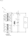
- Fig. 1 shows a configuration of an dielectric elastomer power generation system according to the present invention.
- a dielectric elastomer power generation system A1 according to the present embodiment includes a piezoelectric element 1, a multi-stage voltage multiplier/rectifier circuit 2, a dielectric elastomer power generation element 3, a power storage circuit 4 and a switching unit 5.
- the dielectric elastomer power generation system A1 generates power by using vibration inputs Fv1 and Fv2.
- the piezoelectric element 1 is a piezoelectric power generator.
- the piezoelectric element 1 converts a vibration input into electric power.
- the piezoelectric element 1 features the ability to generate alternating current (AC) power from vibrations having a relatively small amplitude.
- AC alternating current
- the multi-stage voltage multiplier/rectifier circuit 2 boosts and rectifies an input voltage through multiple stages to output a direct current (DC) voltage approximately equal to an integral multiple of the input voltage.
- the multi-stage voltage multiplier/rectifier circuit 2 includes a Cockcroft-Walton circuit.
- the Cockcroft-Walton circuit is composed of a plurality of diodes and a plurality of capacitors connected in multiple stages for increasing an input voltage to a voltage equal to some multiple of the input voltage.
- the multi-stage voltage multiplier/rectifier circuit 2 in the example shown in the figures is a Cockcroft-Walton circuit composed of the number 2n of diodes D1, D2... D2n and the number 2n of capacitors C1, C2...
- the multi-stage voltage multiplier/rectifier circuit 2 produces a DC voltage output equal to n times the peak-to-peak value of the input AC voltage, which is the difference between the maximum voltage (positive peak) and the minimum voltage (negative peak) of the input AC voltage.
- the dielectric elastomer power generation element 3 includes a dielectric elastomer layer 31 and a pair of electrode layers 32 as shown in Figs. 2 and 3 .
- the dielectric elastomer power generation system may include a structural element for transferring external force to the dielectric elastomer power generation element 3, and a mechanism for applying tensile force to the dielectric elastomer power generation element 3 (neither is not illustrated).
- the dielectric elastomer layer 31 is required to have elastic deformability and high dielectric strength.
- Appropriate materials for the dielectric elastomer layer 31 include, but not limited to, silicone elastomers and acrylic elastomers.
- the pair of electrode layers 32 sandwiching the dielectric elastomer layer 31 are components at which the initial charges are applied and the output voltage is produced.
- the electrode layers 32 are made of a material that is electrically conductive and also elastically deformable to comply with elastic deformation of the dielectric elastomer layer 31. Examples of such a material include an elastically deformable material containing fillers to impart electrical conductivity to the material. Carbon nanotubes may be a preferable example of the fillers.
- the dielectric elastomer power generation element 3 When no external force or constraint is applied to the dielectric elastomer power generation element 3 and no voltage is applied to the pair of electrode layers 32, the dielectric elastomer power generation element 3 is in a relaxed state having a natural length. When an external force is applied, the dielectric elastomer layer 31 will deform elastically.
- the power storage circuit 4 receives electric power generated by the dielectric elastomer power generation element 3 and serves as a power storage means of the dielectric elastomer power generation system A1.
- the power storage circuit 4 is not specifically limited in configuration as long as it has a sufficient capacity for storing electric power generated by the dielectric elastomer power generation element 3.
- the power storage circuit 4 may be constituted by a secondary battery, such as a nickel metal hydride battery or a lithium-ion battery.
- the power storage circuit 4 may also be provided with a step-down circuit that lowers the input voltage to a suitable voltage for the secondary battery.
- the switching unit 5 switches the electrical connection between the dielectric elastomer power generation element 3, the multi-stage voltage multiplier/rectifier circuit 2 and the power storage circuit 4.
- the switching unit 5 is not specifically limited in configuration and may include a semiconductor switching element or a switching module that mechanically switches the electrical connection.
- the switching unit 5 may additionally include a detecting means for detecting at least one of, possibly all of the vibration state of the piezoelectric element 1, the state of voltage application to the multi-stage voltage multiplier/rectifier circuit 2, and the stretched or contracted state of the dielectric elastomer power generation element 3.
- the switching unit 5 may further include a control unit for determining whether to switch the electrical connection based on the result of detection by the detection means.
- a vibration input Fv1 is supplied to the piezoelectric element 1.
- the vibration input Fv1 may be vibrations caused by natural energy, for example.
- the vibration input Fv1 of relatively small amplitude is sufficient for the piezoelectric element 1 to generate power. Therefore, vibrations having amplitude too small for the dielectric elastomer power generation element 3 to generate power may be used as the vibration input Fv1.
- vibrations having time-varying amplitude may be used as the vibration input Fv1 during the time the amplitude is too small for power generation by the dielectric elastomer power generation element 3.
- Power generated by the piezoelectric element 1 is supplied to the multi-stage voltage multiplier/rectifier circuit 2.
- the power generated by the piezoelectric element 1 from the vibration input Fv1 is AC power having a peak voltage V1.
- the voltage accumulated on the number 2n of capacitors C1, C2... C2n becomes higher.
- the DC voltage V2 output from the multi-stage voltage multiplier/rectifier circuit 2 will be equal to 2n times the input voltage V1.
- a vibration input Fv2 is supplied to the dielectric elastomer power generation element 3.
- the switching unit 5 is operated to connect the multi-stage voltage multiplier/rectifier circuit 2 to the dielectric elastomer power generation element 3.
- vibrations having amplitude sufficient for the dielectric elastomer power generation element 3 to generate power may be used.
- vibrations having time-varying amplitude may be used as the vibration input Fv2 during the time the amplitude is sufficiently large for power generation by the dielectric elastomer power generation element 3. That is, the vibration input Fv1 and the vibration input Fv2 may be obtained from a single source of vibrations whose amplitude changes with time.
- the vibration input Fv1 induces an external force acting to pull the dielectric elastomer power generation element 3 in the vertical directions as seen in the figure.
- the dielectric elastomer layer 31 of the dielectric elastomer power generation element 3 is stretched vertically as seen in the figure.
- the dielectric elastomer layer 31 in this state has an increased area and a reduced thickness.
- Each electrode layer 32 also has an increased area as it deforms by following the deformation of the dielectric elastomer layer 31.
- the dielectric elastomer power generation element 3 can serve as a capacitor having a relatively large capacitance Cd1.
- the multi-stage voltage multiplier/rectifier circuit 2 applies the DC voltage V2 to the element 3 as an initial voltage.
- the electric current Iq flows and the charge Q accumulates.
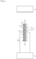
- Fig. 3 shows the state in which the external force applied in Fig. 2 has been reduced or removed, allowing the dielectric elastomer power generation element 3 to contract.
- the switching unit 5 is operated to connect the power storage circuit 4 to the dielectric elastomer power generation element 3.
- the dielectric elastomer layer 31 in this state has a reduced area and an increased thickness.
- Each electrode layer 32 also has a reduced area as it deforms by following the deformation of the dielectric elastomer layer 31.
- the dielectric elastomer power generation element 3 serves as a capacitor having a capacitance Cd2 that is smaller than the capacitance Cd1 noted above. Nevertheless, the charge Q accumulated on the pair of electrode layers 32 remains constant.
- the ratio of the voltage V3 to the DC voltage V2 is inversely proportional to the ratio of the capacitance Cd2 to the capacitance Cd1.
- the charge accumulated on the pair of electrode layers 32 is received as the output current Iw by the power storage circuit 4.
- the output power obtained is greater than the power required to apply the initial voltage.
- the output voltage is stored on the power storage circuit 4. The sequence of operations described above is repeated to store the electric power generated by the dielectric elastomer power generation element 3 in the power storage circuit 4.
- the electric power needed for applying an initial voltage to the dielectric elastomer power generation element 3 is generated by the piezoelectric element 1.
- AC voltage produced by the piezoelectric element 1 is boosted and rectified by the multi-stage voltage multiplier/rectifier circuit before it is applied as an initial voltage to the dielectric elastomer power generation element.
- a higher initial voltage is preferred, provided that the initial voltage is within a range for the dielectric elastomer power generation element 3 to operate in the power generation mode. That is, the present embodiment is effective to reduce the cost of constructing the dielectric elastomer power generation system and increase the amount of power generation.
- the multi-stage voltage multiplier/rectifier circuit 2 includes a Cockcroft-Walton circuit, whereby the multi-stage voltage multiplier/rectifier circuit 2 can be constituted by a plurality of diodes and a plurality of capacitors.
- the value of the voltage to be applied at each stage is equal to the peak-to-peak value of the input AC voltage. Consequently, the diodes and capacitors are not required to have an extremely high dielectric strength.
- the multi-stage voltage multiplier/rectifier circuit 2 doubles as booster and rectifier, which contributes to reducing the number of components otherwise required for the dielectric elastomer power generation system A1.
- the multi-stage voltage multiplier/rectifier circuit 2 can therefore be constructed at a lower cost.
- the mean time between failures can be extended, enabling the dielectric elastomer power generation system A1 to be more reliable.
- the dielectric elastomer power generation system according to the present invention is not limited to the specific embodiments described above.
- the specific configuration of each part of the dielectric elastomer power generation system according to the present invention may be varied in design in many ways.
Landscapes
- Engineering & Computer Science (AREA)
- Power Engineering (AREA)
- General Electrical Machinery Utilizing Piezoelectricity, Electrostriction Or Magnetostriction (AREA)
- Rectifiers (AREA)
Abstract
Description
- The present invention relates to dielectric elastomer power generation systems.
- A dielectric elastomer element includes a dielectric elastomer layer sandwiched between a pair of electrode layers, and various types have been developed for actuation and power generation purposes.
Patent documents -
- Patent Document 1:
JP-B-5479659 - Patent Document 2:
JP-B-5509350 - The working principle of power generation by a dielectric elastomer element is to use the capacitance change of the dielectric elastomer element induced by external force to produce a higher voltage than the voltage of initially applied charges (hereinafter, initial voltage). For increasing the amount of power generated by the dielectric elastomer power generation system, it is desirable to apply a higher initial voltage to the dielectric elastomer element. However, applying such an initial voltage requires, for example, a dedicated power supply circuit, thereby leading to increase in the complexity and cost of the dielectric elastomer power generation system.
- The present invention has been conceived under the circumstances described above and aims to provide a dielectric elastomer power generation system that can be constructed at a lower cost and yet is capable of generating an increased amount of power.
- The present invention provides a dielectric elastomer power generation system comprising a dielectric elastomer power generation element including a dielectric elastomer layer and a pair of electrodes sandwiching the dielectric elastomer layer. The dielectric elastomer power generation system further comprises a piezoelectric element and a multi-stage voltage multiplier rectifier circuit that boosts and rectifies a voltage generated by the piezoelectric element and applies a resulting voltage to the dielectric elastomer power generation element as initial charge.
- According to a preferred embodiment of the present invention, the multi-stage voltage multiplier rectifier circuit comprises a Cockcroft-Walton circuit.
- The present invention is capable of reducing the system construction cost, while increasing the amount of power generation.
- Other features and advantages of the present invention will be more apparent from detailed description given below with reference to the accompanying drawings.
-
-
Fig. 1 is a view showing a configuration of an dielectric elastomer power generation system according to the present invention. -
Fig. 2 is a schematic diagram illustrating the principle of power generation by a dielectric elastomer power generation element of the dielectric elastomer power generation system ofFig. 1 . -
Fig. 3 is a schematic diagram illustrating the principle of power generation by the dielectric elastomer power generation element of the dielectric elastomer power generation system ofFig. 1 . - Preferred embodiments of the present invention are described below with reference to the drawings.
-
Fig. 1 shows a configuration of an dielectric elastomer power generation system according to the present invention. A dielectric elastomer power generation system A1 according to the present embodiment includes apiezoelectric element 1, a multi-stage voltage multiplier/rectifier circuit 2, a dielectric elastomerpower generation element 3, apower storage circuit 4 and aswitching unit 5. The dielectric elastomer power generation system A1 generates power by using vibration inputs Fv1 and Fv2. - The
piezoelectric element 1 is a piezoelectric power generator. Thepiezoelectric element 1 converts a vibration input into electric power. Thepiezoelectric element 1 features the ability to generate alternating current (AC) power from vibrations having a relatively small amplitude. - The multi-stage voltage multiplier/
rectifier circuit 2 boosts and rectifies an input voltage through multiple stages to output a direct current (DC) voltage approximately equal to an integral multiple of the input voltage. In this embodiment, the multi-stage voltage multiplier/rectifier circuit 2 includes a Cockcroft-Walton circuit. The Cockcroft-Walton circuit is composed of a plurality of diodes and a plurality of capacitors connected in multiple stages for increasing an input voltage to a voltage equal to some multiple of the input voltage. The multi-stage voltage multiplier/rectifier circuit 2 in the example shown in the figures is a Cockcroft-Walton circuit composed of the number 2n of diodes D1, D2... D2n and the number 2n of capacitors C1, C2... C2n that are connected in n stages. The multi-stage voltage multiplier/rectifier circuit 2 produces a DC voltage output equal to n times the peak-to-peak value of the input AC voltage, which is the difference between the maximum voltage (positive peak) and the minimum voltage (negative peak) of the input AC voltage. - The dielectric elastomer
power generation element 3 includes adielectric elastomer layer 31 and a pair ofelectrode layers 32 as shown inFigs. 2 and3 . In addition to the dielectric elastomerpower generation element 3, the dielectric elastomer power generation system may include a structural element for transferring external force to the dielectric elastomerpower generation element 3, and a mechanism for applying tensile force to the dielectric elastomer power generation element 3 (neither is not illustrated). - The
dielectric elastomer layer 31 is required to have elastic deformability and high dielectric strength. Appropriate materials for thedielectric elastomer layer 31 include, but not limited to, silicone elastomers and acrylic elastomers. - The pair of
electrode layers 32 sandwiching thedielectric elastomer layer 31 are components at which the initial charges are applied and the output voltage is produced. Theelectrode layers 32 are made of a material that is electrically conductive and also elastically deformable to comply with elastic deformation of thedielectric elastomer layer 31. Examples of such a material include an elastically deformable material containing fillers to impart electrical conductivity to the material. Carbon nanotubes may be a preferable example of the fillers. - When no external force or constraint is applied to the dielectric elastomer
power generation element 3 and no voltage is applied to the pair ofelectrode layers 32, the dielectric elastomerpower generation element 3 is in a relaxed state having a natural length. When an external force is applied, thedielectric elastomer layer 31 will deform elastically. - The
power storage circuit 4 receives electric power generated by the dielectric elastomerpower generation element 3 and serves as a power storage means of the dielectric elastomer power generation system A1. Thepower storage circuit 4 is not specifically limited in configuration as long as it has a sufficient capacity for storing electric power generated by the dielectric elastomerpower generation element 3. Thepower storage circuit 4 may be constituted by a secondary battery, such as a nickel metal hydride battery or a lithium-ion battery. Thepower storage circuit 4 may also be provided with a step-down circuit that lowers the input voltage to a suitable voltage for the secondary battery. - The
switching unit 5 switches the electrical connection between the dielectric elastomerpower generation element 3, the multi-stage voltage multiplier/rectifier circuit 2 and thepower storage circuit 4. Theswitching unit 5 is not specifically limited in configuration and may include a semiconductor switching element or a switching module that mechanically switches the electrical connection. To enable the dielectric elastomer power generation system A1 to operate as described below, theswitching unit 5 may additionally include a detecting means for detecting at least one of, possibly all of the vibration state of thepiezoelectric element 1, the state of voltage application to the multi-stage voltage multiplier/rectifier circuit 2, and the stretched or contracted state of the dielectric elastomerpower generation element 3. Theswitching unit 5 may further include a control unit for determining whether to switch the electrical connection based on the result of detection by the detection means. - Next, examples of operations of the dielectric elastomer power generation system A1 will be described.
- As shown in
Fig. 1 , a vibration input Fv1 is supplied to thepiezoelectric element 1. The vibration input Fv1 may be vibrations caused by natural energy, for example. The vibration input Fv1 of relatively small amplitude is sufficient for thepiezoelectric element 1 to generate power. Therefore, vibrations having amplitude too small for the dielectric elastomerpower generation element 3 to generate power may be used as the vibration input Fv1. Also, vibrations having time-varying amplitude may be used as the vibration input Fv1 during the time the amplitude is too small for power generation by the dielectric elastomerpower generation element 3. - Power generated by the
piezoelectric element 1 is supplied to the multi-stage voltage multiplier/rectifier circuit 2. The power generated by thepiezoelectric element 1 from the vibration input Fv1 is AC power having a peak voltage V1. Each time the AC power supplied to the multi-stage voltage multiplier/rectifier circuit 2 switches between positive and negative voltages, the voltage accumulated on the number 2n of capacitors C1, C2... C2n becomes higher. For example, when the application of AC voltage generated by thepiezoelectric element 1 from the vibration input Fv1 is sufficiently conducted, the DC voltage V2 output from the multi-stage voltage multiplier/rectifier circuit 2 will be equal to 2n times the input voltage V1. - Next, as shown in
Fig. 1 , a vibration input Fv2 is supplied to the dielectric elastomerpower generation element 3. In the figure, theswitching unit 5 is operated to connect the multi-stage voltage multiplier/rectifier circuit 2 to the dielectric elastomerpower generation element 3. As the vibration input Fv2, vibrations having amplitude sufficient for the dielectric elastomerpower generation element 3 to generate power may be used. Also, vibrations having time-varying amplitude may be used as the vibration input Fv2 during the time the amplitude is sufficiently large for power generation by the dielectric elastomerpower generation element 3. That is, the vibration input Fv1 and the vibration input Fv2 may be obtained from a single source of vibrations whose amplitude changes with time. - In
Fig. 2 , the vibration input Fv1 induces an external force acting to pull the dielectric elastomerpower generation element 3 in the vertical directions as seen in the figure. As a result, thedielectric elastomer layer 31 of the dielectric elastomerpower generation element 3 is stretched vertically as seen in the figure. Thedielectric elastomer layer 31 in this state has an increased area and a reduced thickness. Eachelectrode layer 32 also has an increased area as it deforms by following the deformation of thedielectric elastomer layer 31. In this state, the dielectric elastomerpower generation element 3 can serve as a capacitor having a relatively large capacitance Cd1. While the dielectric elastomerpower generation element 3 is held in this state, the multi-stage voltage multiplier/rectifier circuit 2 applies the DC voltage V2 to theelement 3 as an initial voltage. Upon application of the DC voltage V2 to the dielectric elastomerpower generation element 3 with a capacitance of Cd1, the electric current Iq flows and the charge Q accumulates. -
Fig. 3 shows the state in which the external force applied inFig. 2 has been reduced or removed, allowing the dielectric elastomerpower generation element 3 to contract. In the figure, theswitching unit 5 is operated to connect thepower storage circuit 4 to the dielectric elastomerpower generation element 3. Thedielectric elastomer layer 31 in this state has a reduced area and an increased thickness. Eachelectrode layer 32 also has a reduced area as it deforms by following the deformation of thedielectric elastomer layer 31. In this state, the dielectric elastomerpower generation element 3 serves as a capacitor having a capacitance Cd2 that is smaller than the capacitance Cd1 noted above. Nevertheless, the charge Q accumulated on the pair of electrode layers 32 remains constant. Thus, the ratio of the voltage V3 to the DC voltage V2 is inversely proportional to the ratio of the capacitance Cd2 to the capacitance Cd1. The charge accumulated on the pair of electrode layers 32 is received as the output current Iw by thepower storage circuit 4. In this way, when thedielectric elastomer layer 31 is in the contracted state, the output power obtained is greater than the power required to apply the initial voltage. The output voltage is stored on thepower storage circuit 4. The sequence of operations described above is repeated to store the electric power generated by the dielectric elastomerpower generation element 3 in thepower storage circuit 4. - Next, advantages of the dielectric elastomer power generation system A1 will be described.
- According to the present embodiment, the electric power needed for applying an initial voltage to the dielectric elastomer
power generation element 3 is generated by thepiezoelectric element 1. Thus, there is no need to provide a dedicated power source or circuit for the application of an initial voltage to the dielectric elastomerpower generation element 3. In addition, AC voltage produced by thepiezoelectric element 1 is boosted and rectified by the multi-stage voltage multiplier/rectifier circuit before it is applied as an initial voltage to the dielectric elastomer power generation element. To increase the amount of power generated by the dielectric elastomerpower generation element 3, a higher initial voltage is preferred, provided that the initial voltage is within a range for the dielectric elastomerpower generation element 3 to operate in the power generation mode. That is, the present embodiment is effective to reduce the cost of constructing the dielectric elastomer power generation system and increase the amount of power generation. - In addition, the multi-stage voltage multiplier/
rectifier circuit 2 includes a Cockcroft-Walton circuit, whereby the multi-stage voltage multiplier/rectifier circuit 2 can be constituted by a plurality of diodes and a plurality of capacitors. In addition, the value of the voltage to be applied at each stage is equal to the peak-to-peak value of the input AC voltage. Consequently, the diodes and capacitors are not required to have an extremely high dielectric strength. In addition, the multi-stage voltage multiplier/rectifier circuit 2 doubles as booster and rectifier, which contributes to reducing the number of components otherwise required for the dielectric elastomer power generation system A1. The multi-stage voltage multiplier/rectifier circuit 2 can therefore be constructed at a lower cost. In addition, the mean time between failures can be extended, enabling the dielectric elastomer power generation system A1 to be more reliable. - The dielectric elastomer power generation system according to the present invention is not limited to the specific embodiments described above. The specific configuration of each part of the dielectric elastomer power generation system according to the present invention may be varied in design in many ways.
Claims (2)
- A dielectric elastomer power generation system comprising:a dielectric elastomer power generation element including a dielectric elastomer layer and a pair of electrodes sandwiching the dielectric elastomer layer;a piezoelectric element; anda multi-stage voltage multiplier/rectifier circuit that boosts and rectifies a voltage generated by the piezoelectric element and applies a resulting voltage to the dielectric elastomer power generation element as initial charge.
- The dielectric elastomer power generation system according to Claim 1, wherein the multi-stage voltage multiplier/rectifier circuit comprises a Cockcroft-Walton circuit.
Applications Claiming Priority (2)
| Application Number | Priority Date | Filing Date | Title |
|---|---|---|---|
| JP2018150278 | 2018-08-09 | ||
| PCT/JP2019/027307 WO2020031600A1 (en) | 2018-08-09 | 2019-07-10 | Dielectric elastomer power generation system |
Publications (2)
| Publication Number | Publication Date |
|---|---|
| EP3836385A1 true EP3836385A1 (en) | 2021-06-16 |
| EP3836385A4 EP3836385A4 (en) | 2022-05-04 |
Family
ID=69415557
Family Applications (1)
| Application Number | Title | Priority Date | Filing Date |
|---|---|---|---|
| EP19846663.3A Withdrawn EP3836385A4 (en) | 2018-08-09 | 2019-07-10 | POWER GENERATION SYSTEM WITH DIELECTRIC ELASTOMER |
Country Status (5)
| Country | Link |
|---|---|
| US (1) | US11909337B2 (en) |
| EP (1) | EP3836385A4 (en) |
| JP (1) | JPWO2020031600A1 (en) |
| CN (1) | CN112514235A (en) |
| WO (1) | WO2020031600A1 (en) |
Families Citing this family (5)
| Publication number | Priority date | Publication date | Assignee | Title |
|---|---|---|---|---|
| JP7015747B2 (en) * | 2018-07-30 | 2022-02-03 | 正毅 千葉 | Dielectric elastomer transducer system |
| JP6800928B2 (en) * | 2018-09-27 | 2020-12-16 | 正毅 千葉 | Dielectric elastomer vibration system and power supply |
| JPWO2020175257A1 (en) * | 2019-02-28 | 2020-09-03 | ||
| CN113595433B (en) * | 2021-07-08 | 2023-04-18 | 浙江师范大学 | Dielectric elastomer energy collection system and method |
| CN115284269A (en) * | 2022-01-18 | 2022-11-04 | 浙江师范大学 | Bionic self-driven electrostatic execution system |
Family Cites Families (13)
| Publication number | Priority date | Publication date | Assignee | Title |
|---|---|---|---|---|
| JPS5245486A (en) | 1975-10-07 | 1977-04-09 | Matsushita Electronics Corp | Vessel for packing ring material |
| EP1259992B1 (en) | 2000-02-23 | 2011-10-05 | SRI International | Biologically powered electroactive polymer generators |
| US8643253B1 (en) * | 2007-09-03 | 2014-02-04 | Joseph Anthony Micallef | Piezoelectric ultracapacitors |
| EP2539948B1 (en) * | 2010-02-24 | 2017-11-01 | Auckland Uniservices Limited | Electrical components and circuits including said components |
| JP2012228069A (en) * | 2011-04-19 | 2012-11-15 | Panasonic Corp | Floor device and floor panel for use in the same |
| CN202110953U (en) * | 2011-05-25 | 2012-01-11 | 四川云翔电子科技有限公司 | New Film Capacitors |
| KR20130042984A (en) * | 2011-10-19 | 2013-04-29 | 김광하 | Electric power generator using artificial vibration energy, and power plant system |
| DK2847856T3 (en) | 2012-05-10 | 2018-08-06 | Single Buoy Moorings | Charging / Discharging Circuits for Electromechanical Energy Conversion and Electromechanical Energy Conversion System |
| JP6101983B2 (en) * | 2012-12-27 | 2017-03-29 | 日本特殊陶業株式会社 | Power generation circuit and transmitter using the same |
| JP6370597B2 (en) * | 2014-04-30 | 2018-08-08 | 日置電機株式会社 | Voltage generation circuit |
| JP2016073366A (en) * | 2014-10-03 | 2016-05-12 | 克弥 西沢 | Radio communication device having power generation function by walking, and radio communication and positioning functions, and a pedestrian's position monitoring system using the radio communication device as inner sole |
| US10250235B2 (en) * | 2015-11-30 | 2019-04-02 | The Regents Of The University Of Michigan | Full-wave charge pump with low-voltage startup |
| JP6937099B2 (en) * | 2016-07-27 | 2021-09-22 | 正毅 千葉 | Dielectric elastomer power generator |
-
2019
- 2019-07-10 US US17/264,845 patent/US11909337B2/en active Active
- 2019-07-10 CN CN201980050227.8A patent/CN112514235A/en active Pending
- 2019-07-10 WO PCT/JP2019/027307 patent/WO2020031600A1/en not_active Ceased
- 2019-07-10 EP EP19846663.3A patent/EP3836385A4/en not_active Withdrawn
- 2019-07-10 JP JP2020536398A patent/JPWO2020031600A1/en not_active Ceased
Also Published As
| Publication number | Publication date |
|---|---|
| US20210297013A1 (en) | 2021-09-23 |
| EP3836385A4 (en) | 2022-05-04 |
| US11909337B2 (en) | 2024-02-20 |
| WO2020031600A1 (en) | 2020-02-13 |
| CN112514235A (en) | 2021-03-16 |
| JPWO2020031600A1 (en) | 2021-09-24 |
Similar Documents
| Publication | Publication Date | Title |
|---|---|---|
| US11909337B2 (en) | Dielectric elastomer power generation system | |
| US7030597B2 (en) | Photovoltaic-type charger | |
| CN201054553Y (en) | Power supply device for radio sensor network node based on piezoelectric porcelain vibration power generation | |
| Ram et al. | Ultra-low power solar energy harvester for IoT edge node devices | |
| CN105634323A (en) | Electret thin film based energy collector | |
| CN205490228U (en) | Energy gatherer based on electret film | |
| JP2016127656A (en) | Power storage device that stores power generated by energy harvesting elements | |
| Panigrahi et al. | Analysis, design, and implementation of an elastomer generator based energy harvesting scheme | |
| Zhang et al. | A conditioning system for high-voltage electrostatic/triboelectric energy harvesters using bennet doubler and self-actuated hysteresis switch | |
| JP2008141840A (en) | Generating set using electric field responsive high polymer | |
| US11218091B2 (en) | Dielectric elastomer power generation system | |
| US11489460B2 (en) | Vibration-driven energy harvester | |
| Zhang et al. | High-voltage MEMS plasma switch for boosting the energy transfer efficiency in triboelectric nanogenerators | |
| CN214069809U (en) | Miniature boost energy storage module | |
| Su et al. | Bennet's Doubler-Extended Converter With Optimized Bias for Enhanced Energy Extraction From Triboelectric Nanogenerators | |
| JP4516587B2 (en) | Power storage circuit | |
| Basset et al. | High-voltage micro-plasma switch for efficient power management of triboelectric kinetic energy harvesters | |
| CN115912985A (en) | Three-output node type hybrid nano generator, mechanical energy power generation device integrating piezoelectric and triboelectric units and application of mechanical energy power generation device | |
| US20220165932A1 (en) | Dielectric elastomer power generation system | |
| CN223977844U (en) | A power-generating keyboard | |
| WO2020099030A1 (en) | Conditioning system for a triboelectric nanogenerator or an electrostatic kinetic energy harvestersystem for a triboelectric nanogenerator or an electrostatic kinetic energy harvester | |
| Lin et al. | An Inductor‐Less Flipping‐Capacitor S&P‐SSHC Rectifier for Piezoelectric Energy Harvesting | |
| Maurath et al. | Adaptive power extraction from micro generators with implicit voltage up-conversion | |
| Su | Interface Circuit Design for Enhanced Energy Harvesting from Triboelectric Nanogenerators | |
| CN114696572A (en) | Electric energy output module |
Legal Events
| Date | Code | Title | Description |
|---|---|---|---|
| STAA | Information on the status of an ep patent application or granted ep patent |
Free format text: STATUS: THE INTERNATIONAL PUBLICATION HAS BEEN MADE |
|
| PUAI | Public reference made under article 153(3) epc to a published international application that has entered the european phase |
Free format text: ORIGINAL CODE: 0009012 |
|
| STAA | Information on the status of an ep patent application or granted ep patent |
Free format text: STATUS: REQUEST FOR EXAMINATION WAS MADE |
|
| 17P | Request for examination filed |
Effective date: 20210211 |
|
| AK | Designated contracting states |
Kind code of ref document: A1 Designated state(s): AL AT BE BG CH CY CZ DE DK EE ES FI FR GB GR HR HU IE IS IT LI LT LU LV MC MK MT NL NO PL PT RO RS SE SI SK SM TR |
|
| DAV | Request for validation of the european patent (deleted) | ||
| DAX | Request for extension of the european patent (deleted) | ||
| A4 | Supplementary search report drawn up and despatched |
Effective date: 20220404 |
|
| RIC1 | Information provided on ipc code assigned before grant |
Ipc: H02N 1/08 20060101ALI20220329BHEP Ipc: H01L 41/193 20060101ALI20220329BHEP Ipc: H01L 41/113 20060101ALI20220329BHEP Ipc: H02N 2/18 20060101AFI20220329BHEP |
|
| RIN1 | Information on inventor provided before grant (corrected) |
Inventor name: UEJIMA, MITSUGU Inventor name: TAKESHITA, MAKOTO Inventor name: WAKI, MIKIO Inventor name: CHIBA, SEIKI |
|
| RAP3 | Party data changed (applicant data changed or rights of an application transferred) |
Owner name: ZEON CORPORATION Owner name: WAKI, MIKIO Owner name: CHIBA, SEIKI |
|
| STAA | Information on the status of an ep patent application or granted ep patent |
Free format text: STATUS: THE APPLICATION HAS BEEN WITHDRAWN |
|
| 18W | Application withdrawn |
Effective date: 20241128 |