EP3836371A1 - Enhanced motor assembly for clothes dryer machine and clothes dryer machine comprising said assembly - Google Patents
Enhanced motor assembly for clothes dryer machine and clothes dryer machine comprising said assembly Download PDFInfo
- Publication number
- EP3836371A1 EP3836371A1 EP21156377.0A EP21156377A EP3836371A1 EP 3836371 A1 EP3836371 A1 EP 3836371A1 EP 21156377 A EP21156377 A EP 21156377A EP 3836371 A1 EP3836371 A1 EP 3836371A1
- Authority
- EP
- European Patent Office
- Prior art keywords
- motor assembly
- clothes dryer
- driving shaft
- dryer machine
- internal stator
- Prior art date
- Legal status (The legal status is an assumption and is not a legal conclusion. Google has not performed a legal analysis and makes no representation as to the accuracy of the status listed.)
- Granted
Links
Images



Classifications
-
- D—TEXTILES; PAPER
- D06—TREATMENT OF TEXTILES OR THE LIKE; LAUNDERING; FLEXIBLE MATERIALS NOT OTHERWISE PROVIDED FOR
- D06F—LAUNDERING, DRYING, IRONING, PRESSING OR FOLDING TEXTILE ARTICLES
- D06F58/00—Domestic laundry dryers
- D06F58/02—Domestic laundry dryers having dryer drums rotating about a horizontal axis
- D06F58/04—Details
-
- D—TEXTILES; PAPER
- D06—TREATMENT OF TEXTILES OR THE LIKE; LAUNDERING; FLEXIBLE MATERIALS NOT OTHERWISE PROVIDED FOR
- D06F—LAUNDERING, DRYING, IRONING, PRESSING OR FOLDING TEXTILE ARTICLES
- D06F58/00—Domestic laundry dryers
- D06F58/02—Domestic laundry dryers having dryer drums rotating about a horizontal axis
- D06F58/04—Details
- D06F58/08—Driving arrangements
-
- H—ELECTRICITY
- H02—GENERATION; CONVERSION OR DISTRIBUTION OF ELECTRIC POWER
- H02K—DYNAMO-ELECTRIC MACHINES
- H02K16/00—Machines with more than one rotor or stator
-
- D—TEXTILES; PAPER
- D06—TREATMENT OF TEXTILES OR THE LIKE; LAUNDERING; FLEXIBLE MATERIALS NOT OTHERWISE PROVIDED FOR
- D06F—LAUNDERING, DRYING, IRONING, PRESSING OR FOLDING TEXTILE ARTICLES
- D06F58/00—Domestic laundry dryers
- D06F58/20—General details of domestic laundry dryers
-
- H—ELECTRICITY
- H02—GENERATION; CONVERSION OR DISTRIBUTION OF ELECTRIC POWER
- H02K—DYNAMO-ELECTRIC MACHINES
- H02K1/00—Details of the magnetic circuit
- H02K1/06—Details of the magnetic circuit characterised by the shape, form or construction
- H02K1/22—Rotating parts of the magnetic circuit
- H02K1/27—Rotor cores with permanent magnets
- H02K1/2786—Outer rotors
-
- H—ELECTRICITY
- H02—GENERATION; CONVERSION OR DISTRIBUTION OF ELECTRIC POWER
- H02K—DYNAMO-ELECTRIC MACHINES
- H02K1/00—Details of the magnetic circuit
- H02K1/06—Details of the magnetic circuit characterised by the shape, form or construction
- H02K1/22—Rotating parts of the magnetic circuit
- H02K1/27—Rotor cores with permanent magnets
- H02K1/2786—Outer rotors
- H02K1/2787—Outer rotors the magnetisation axis of the magnets being perpendicular to the rotor axis
- H02K1/2789—Outer rotors the magnetisation axis of the magnets being perpendicular to the rotor axis the rotor consisting of two or more circumferentially positioned magnets
- H02K1/2791—Surface mounted magnets; Inset magnets
-
- H—ELECTRICITY
- H02—GENERATION; CONVERSION OR DISTRIBUTION OF ELECTRIC POWER
- H02K—DYNAMO-ELECTRIC MACHINES
- H02K16/00—Machines with more than one rotor or stator
- H02K16/04—Machines with one rotor and two stators
-
- H—ELECTRICITY
- H02—GENERATION; CONVERSION OR DISTRIBUTION OF ELECTRIC POWER
- H02K—DYNAMO-ELECTRIC MACHINES
- H02K21/00—Synchronous motors having permanent magnets; Synchronous generators having permanent magnets
- H02K21/12—Synchronous motors having permanent magnets; Synchronous generators having permanent magnets with stationary armatures and rotating magnets
- H02K21/22—Synchronous motors having permanent magnets; Synchronous generators having permanent magnets with stationary armatures and rotating magnets with magnets rotating around the armatures, e.g. flywheel magnetos
-
- H—ELECTRICITY
- H02—GENERATION; CONVERSION OR DISTRIBUTION OF ELECTRIC POWER
- H02K—DYNAMO-ELECTRIC MACHINES
- H02K7/00—Arrangements for handling mechanical energy structurally associated with dynamo-electric machines, e.g. structural association with mechanical driving motors or auxiliary dynamo-electric machines
- H02K7/10—Structural association with clutches, brakes, gears, pulleys or mechanical starters
- H02K7/1004—Structural association with clutches, brakes, gears, pulleys or mechanical starters with pulleys
- H02K7/1008—Structural association with clutches, brakes, gears, pulleys or mechanical starters with pulleys structurally associated with the machine rotor
-
- D—TEXTILES; PAPER
- D06—TREATMENT OF TEXTILES OR THE LIKE; LAUNDERING; FLEXIBLE MATERIALS NOT OTHERWISE PROVIDED FOR
- D06F—LAUNDERING, DRYING, IRONING, PRESSING OR FOLDING TEXTILE ARTICLES
- D06F2103/00—Parameters monitored or detected for the control of domestic laundry washing machines, washer-dryers or laundry dryers
- D06F2103/28—Air properties
- D06F2103/34—Humidity
-
- D—TEXTILES; PAPER
- D06—TREATMENT OF TEXTILES OR THE LIKE; LAUNDERING; FLEXIBLE MATERIALS NOT OTHERWISE PROVIDED FOR
- D06F—LAUNDERING, DRYING, IRONING, PRESSING OR FOLDING TEXTILE ARTICLES
- D06F2103/00—Parameters monitored or detected for the control of domestic laundry washing machines, washer-dryers or laundry dryers
- D06F2103/44—Current or voltage
-
- D—TEXTILES; PAPER
- D06—TREATMENT OF TEXTILES OR THE LIKE; LAUNDERING; FLEXIBLE MATERIALS NOT OTHERWISE PROVIDED FOR
- D06F—LAUNDERING, DRYING, IRONING, PRESSING OR FOLDING TEXTILE ARTICLES
- D06F2105/00—Systems or parameters controlled or affected by the control systems of washing machines, washer-dryers or laundry dryers
- D06F2105/46—Drum speed; Actuation of motors, e.g. starting or interrupting
-
- H—ELECTRICITY
- H02—GENERATION; CONVERSION OR DISTRIBUTION OF ELECTRIC POWER
- H02K—DYNAMO-ELECTRIC MACHINES
- H02K5/00—Casings; Enclosures; Supports
- H02K5/04—Casings or enclosures characterised by the shape, form or construction thereof
- H02K5/15—Mounting arrangements for bearing-shields or end plates
-
- H—ELECTRICITY
- H02—GENERATION; CONVERSION OR DISTRIBUTION OF ELECTRIC POWER
- H02K—DYNAMO-ELECTRIC MACHINES
- H02K7/00—Arrangements for handling mechanical energy structurally associated with dynamo-electric machines, e.g. structural association with mechanical driving motors or auxiliary dynamo-electric machines
- H02K7/14—Structural association with mechanical loads, e.g. with hand-held machine tools or fans
Definitions
- Clothes dryer machines of the various kind and type are used both in the domestic and industrial areas to remove moisture from garments and/or other textile products, usually following a washing cycle performed thereon.
- Said clothes dryer machines have a rotating drum intended to house the laundry to be dried.
- the machine further comprises at least one hot-air ventilation system introduced in the drum with a drying function.
- a second cold-air ventilation system is also provided, which is intended, through a heat exchanger, to dehumidify the drying air for a subsequent recirculation in the rotating drum.
- the fan or the two fans are keyed on a driving shaft, which the rotating drum is also connected to by means of a belt transmission.
- the driving shaft is integral with the rotor of an electric motor, the latter being supported in a tilting manner by the frame of the clothes dryer machine.
- Document CN 1 165 654 C discloses a direct drive motor assembly for a dryer, while documents EP 2 395 144 A2 and EP 1 860 229 A1 disclose indirect drive motor assemblies according to the prior art.
- the technical problem underlying the present invention is therefore to conceive a motor assembly which allows solving the above described drawbacks of the prior art, and in particular which allows improving the energy effectiveness of the clothes dryer machine without resort to a re-design of the entire appliance.
- the above suggested external rotor architecture allows the integration of the assembly, equipped with a separate motorization for the fan and the drum, within the traditional dimensions of a motor assembly for a clothes dryer machine.
- the motor assembly may thus be housed within the volumes of the existing clothes dryer machine models, namely it allows making new models with enhanced energy performance without requiring a complete re-design of the previous machines.
- one or more air movement fans may be coupled to the driving shaft, according to the specific needs connected to the type of operation of the domestic appliance whereon the motor assembly is mounted. Furthermore, the fan may be directly keyed on the driving shaft or constrained thereto by means of a kinematic transmission of any type.
- the motor assembly may comprise a main body, which the first internal stator and the second internal stator are integral with. Said main body may be mounted tilting with respect to the frame of the clothes dryer machine, analogously to the single electric motor of the clothes dryer machines known in the art.
- the driving shaft will be rotatably supported by the frame of the machine, for instance by means of bearings; the main body is in turn rotatably supported by the driving shaft.
- the latter is constrained in a tilting manner to the frame by means of a connection spring contrasted by the torque of a transmission belt wound around an idler pulley which is integral with the main body itself.
- the first internal stator and the second internal stator face two opposite ends of said main body, said first outer rotor and said second outer rotor being cup-shaped and closing said ends.
- the main body along with the rotors, may therefore define a housing casing for one or more connection and/or control boards of the first and of the second electric motor.
- connection board indicates a board having a mere function of electric connection and without a control function.
- the motor assembly preferably comprises an idler pulley, which is rotatably mounted on a pin that is integral with said main body.
- the idler pulley is arranged axially in line with said pulley along a longitudinal axis of said driving shaft.
- the pin is preferably mounted parallel to the longitudinal axis on an eccentric portion of the main body, said eccentric portion also providing an attachment for a connection spring to the frame of the clothes dryer machine.
- the eccentric portion protrudes with respect to the cylindrical peripheral wall hereinafter defined.
- the main body may advantageously comprise a sleeve - preferably coupled to the driving shaft by means of at least two interposed ball bearings - rotatably coupled above the driving shaft, said first internal stator and said second internal stator being both supported by said sleeve.
- the aforementioned housing casing of the boards may advantageously be defined by a peripheral wall, preferably cylindrical, connected to the sleeve by a central baffle which is orthogonal to the longitudinal axis of the driving shaft.
- the orthogonal central baffle may act as support to the connection and/or control boards of the motors.
- the motors are preferably permanent-magnet synchronous motors, for instance of the three-phase type with star package.
- said first outer rotor and said second outer rotor may both comprise an annular permanent magnet, associated with an internal wall of a rotating cup.
- the magnet may in particular be a plastoferrite ring housed inside a metal ring which is necessary for closing the flow thereof, these two components being co-molded with the plastic cup to make the aforementioned rotor.
- the second outer rotor and the pulley are made in a single piece, said piece being rotatably mounted above said driving shaft with the interposition of at least one bearing - preferably at least two.
- a clothes dryer machine comprising: a rotating drum, which is rotatably mounted with respect to a frame and is intended to house laundry to be dried; and at least one air movement fan, said clothes dryer machine comprising a motor assembly of the previously described type.
- a first embodiment of a motor assembly of a clothes dryer machine 1001 is generically indicated by reference number 1.
- the clothes dryer machine 100 as a whole is schematically represented in figure 1 .
- At least one air path intercepted by an air movement fan 103 is defined, which is keyed on a driving shaft 2 dragged in rotation by a first electric motor 3.
- the clothes dryer machine 100 further comprises a rotating drum 101, which is rotatably mounted with respect to a frame of the machine and which is intended to house a load of laundry to be dried. Said rotating drum is connected to a second electric motor 4 by means of a transmission belt 102.
- the motor assembly 1 comprises a driving shaft 2 having longitudinal axis x. It is rotatably associated with the frame of the clothes dryer machine 100 by means of two ball bearings 20, 21, which are surrounded by a rubber antivibration ring, are arranged at a first end and in an intermediate portion of the shaft itself. At the second end, the bearing has serrations 22 for keying the air movement fan 103.
- both the first electric motor 3 and the second electric motor 4 are arranged.
- the two electric motors 3, 4 are preferably permanent-magnet synchronous electric motors of three-phase type.
- Both of them have an internal stator, a first internal stator 30 and a second internal stator 40, respectively, and an outer rotor, a first outer rotor 35 and a second outer rotor 45, respectively.
- the internal stator 30, 40 of both electric motors 3, 4 is of the star-pack type, that is, it comprises a pack of laminations made of ferromagnetic material having an annular core from which twelve square-section arms 31, 41 depart out, which define the stator magnetic poles.
- the arms 31, 41 of the annular core are inserted inside spools, on which the electric windings of the stator are arranged in a per se known manner.
- the internal stators 30, 40 of the two electric motors 3, 4 are supported by a same main body 6, which is rotatably mounted above a portion of the driving shaft 2 that is intermediate to the two aforementioned ball bearings 20, 21.
- the portion of the main body 6 which supports the two internal stators 30, 40 at its two ends is a sleeve 62, which is in turn supported by the driving shaft 2 having interposed ball bearings.
- a central baffle 63 which connects it to a cylindrical peripheral wall 64, coaxial to the sleeve 62 itself, develops radially.
- the cylindric peripheral wall 64 is covered, at its opposite ends, by the cup of the outer rotors 35, 45.
- a containment casing which encloses, in addition to the two internal stators 30, 40, a control board 8 attached to the central baffle 63, in the present application example on the side of the first electric motor 3.
- the control board 8 arranged to serve both electric motors 3, 4, is connected to a power input 9a and to a signal input 9b which open on the peripheral wall 64.
- the central body 6 also comprises an eccentric portion 60, which protrudes laterally with respect to the peripheral wall 64. This portion supports a fixed pin 70, whereon an idler pulley 7 is mounted idle by interposition of two ball bearings.
- an attachment 61 for a connection spring to the frame of the clothes dryer machine 100 is provided, to allow a floating connection mode which is traditionally used to constrain the actuating electric motors in the prior art machines.
- the second outer rotor 45 is rotatably mounted on the driving shaft 2 by means of ball bearings. It has a tubular appendix away from the second internal stator 30, namely protruding with respect to the convex part of the rotor cup.
- the tubular appendix defines a pulley 5 and has a plurality of transmission throats whereon the transmission belt 102 to the rotating drum 101 wounds.
- a second embodiment of a motor assembly of a clothes dryer machine 100 is generically indicated with reference number 1'.
- Said embodiment is substantially identical to the previous one, to the description of which reference is made, except for the control mode of the two electric motors 3, 4, which occurs remotely and not onboard a card integrated in the unit.
- connection boards 8'a, 8'b are arranged on the two sides of the central baffle 63, from the side of the electric motor 3, 4 thereto interlocked.
Landscapes
- Engineering & Computer Science (AREA)
- Power Engineering (AREA)
- Textile Engineering (AREA)
- Detail Structures Of Washing Machines And Dryers (AREA)
Abstract
Description
- The present invention, in its more general aspect, relates to a motor assembly which allows the operation of a clothes dryer machine.
- Therefore, the technical field of the invention relates to clothes dryer machines. It should be noted that the generic term "clothes dryer machine" used in the present description is intended to also include machines which, in addition to the drying function, also integrates a washing function of the laundry.
- Clothes dryer machines of the various kind and type are used both in the domestic and industrial areas to remove moisture from garments and/or other textile products, usually following a washing cycle performed thereon.
- Said clothes dryer machines have a rotating drum intended to house the laundry to be dried. The machine further comprises at least one hot-air ventilation system introduced in the drum with a drying function. In some types of condensing clothes dryer machines, a second cold-air ventilation system is also provided, which is intended, through a heat exchanger, to dehumidify the drying air for a subsequent recirculation in the rotating drum.
- The above described machines thus comprise two or three motorized components: the rotating drum and one or two air-movement fans.
- Traditionally, in compliance with a criterion of economy and simplicity of construction, a single electric motor for the motorization of all the above components has been used.
- In particular, the fan or the two fans are keyed on a driving shaft, which the rotating drum is also connected to by means of a belt transmission. The driving shaft is integral with the rotor of an electric motor, the latter being supported in a tilting manner by the frame of the clothes dryer machine.
- Said constructive configuration, actually used in most machines available on the market, rigidly constrains the speed of the fan to that of the drum. Said compromise is traditionally accepted in favour of the constructive economy of the assembly.
- However, the current optimization needs, driven by the developments in the regulations on the energy classification of household appliances, have made the above speed constraint critical.
- Ideally, it would in fact be preferable to be capable of varying the speed of the ventilation fan based on the phases of the drying cycle and totally independently with respect to the revolutions of the drum.
- Moreover and especially, the speed constraint forces to non-optimal design choices, thus preventing the adoption of fans of large dimensions with a limited number of revolutions per minute, which would allow to develop a high torque by moving large volumes of air.
- By the way, the use of a separate motor for the ventilation fan forces to a complete re-design of the entire clothes dryer machine, inside which the housings are specifically designed for the dimensions of the traditional system. Said re-design is economically onerous and furthermore raises potential compatibility problems with the spare parts available on the market.
-
Document CN 1 165 654 C discloses a direct drive motor assembly for a dryer, whiledocuments EP 2 395 144 A2 andEP 1 860 229 A1 - The technical problem underlying the present invention is therefore to conceive a motor assembly which allows solving the above described drawbacks of the prior art, and in particular which allows improving the energy effectiveness of the clothes dryer machine without resort to a re-design of the entire appliance.
- The above identified technical problem is solved by a motor assembly for a clothes dryer machine, comprising: a driving shaft, which is rotatably associable with a frame of a clothes dryer machine and arranged to drag in rotation at least one air movement fan of said clothes dryer machine; a first electric motor comprising a first internal stator crossed by said driving shaft and rotating relative thereto and a first outer rotor which is integral in rotation with said driving shaft; a second electric motor comprising in turn a second internal stator and a second outer rotor, both crossed by said driving shaft and rotating relative thereto, wherein said second outer rotor is integral with a pulley for actuating a drum of said clothes dryer machine.
- The above suggested external rotor architecture allows the integration of the assembly, equipped with a separate motorization for the fan and the drum, within the traditional dimensions of a motor assembly for a clothes dryer machine. The motor assembly may thus be housed within the volumes of the existing clothes dryer machine models, namely it allows making new models with enhanced energy performance without requiring a complete re-design of the previous machines.
- It is noted that one or more air movement fans may be coupled to the driving shaft, according to the specific needs connected to the type of operation of the domestic appliance whereon the motor assembly is mounted. Furthermore, the fan may be directly keyed on the driving shaft or constrained thereto by means of a kinematic transmission of any type.
- The motor assembly may comprise a main body, which the first internal stator and the second internal stator are integral with. Said main body may be mounted tilting with respect to the frame of the clothes dryer machine, analogously to the single electric motor of the clothes dryer machines known in the art.
- Preferably, the driving shaft will be rotatably supported by the frame of the machine, for instance by means of bearings; the main body is in turn rotatably supported by the driving shaft. The latter is constrained in a tilting manner to the frame by means of a connection spring contrasted by the torque of a transmission belt wound around an idler pulley which is integral with the main body itself.
- Preferably, the first internal stator and the second internal stator face two opposite ends of said main body, said first outer rotor and said second outer rotor being cup-shaped and closing said ends.
- The main body, along with the rotors, may therefore define a housing casing for one or more connection and/or control boards of the first and of the second electric motor.
- In the present text, "connection board" indicates a board having a mere function of electric connection and without a control function.
- In particular, the motor assembly may comprise a unique control board for both the first electric motor and the second electric motor. In this case, a single power input and a single signal input for both motors are provided, preferably in the form of snap connectors defined externally to the housing casing.
- Alternatively to what has been stated above, the control of the two electric motors may be carried out by a unit external to the motor assembly; in this case, the motor assembly comprises a first connection board and a second connection board, which are dedicated to the first electric motor and to the second electric motor, respectively.
- As previously mentioned, the motor assembly preferably comprises an idler pulley, which is rotatably mounted on a pin that is integral with said main body. The idler pulley is arranged axially in line with said pulley along a longitudinal axis of said driving shaft.
- The pin is preferably mounted parallel to the longitudinal axis on an eccentric portion of the main body, said eccentric portion also providing an attachment for a connection spring to the frame of the clothes dryer machine. Preferably, the eccentric portion protrudes with respect to the cylindrical peripheral wall hereinafter defined.
- The main body may advantageously comprise a sleeve - preferably coupled to the driving shaft by means of at least two interposed ball bearings - rotatably coupled above the driving shaft, said first internal stator and said second internal stator being both supported by said sleeve.
- The aforementioned housing casing of the boards may advantageously be defined by a peripheral wall, preferably cylindrical, connected to the sleeve by a central baffle which is orthogonal to the longitudinal axis of the driving shaft.
- The orthogonal central baffle may act as support to the connection and/or control boards of the motors.
- The motors are preferably permanent-magnet synchronous motors, for instance of the three-phase type with star package.
- Thus, said first outer rotor and said second outer rotor may both comprise an annular permanent magnet, associated with an internal wall of a rotating cup. The magnet may in particular be a plastoferrite ring housed inside a metal ring which is necessary for closing the flow thereof, these two components being co-molded with the plastic cup to make the aforementioned rotor.
- Said first internal stator and said second internal stator may both comprise a pack of laminations made of ferromagnetic material, said pack of laminations having an annular core from which a plurality of arms departs out, said arms being covered by spools, on said spools being disposed electric windings.
- Preferably, the second outer rotor and the pulley are made in a single piece, said piece being rotatably mounted above said driving shaft with the interposition of at least one bearing - preferably at least two.
- The previously identified technical problem is also solved by a clothes dryer machine comprising: a rotating drum, which is rotatably mounted with respect to a frame and is intended to house laundry to be dried; and at least one air movement fan, said clothes dryer machine comprising a motor assembly of the previously described type.
- Further features and advantages of the present invention will be clearer from the following description of two preferred embodiments given by way of non-limiting example with reference to the enclosed drawings.
-
-
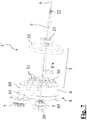
Figure 1 schematically shows a clothes dryer machine according to the present invention; -
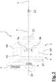
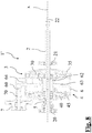
figure 2 shows a side view of a motor assembly according to a first embodiment of the present invention; -
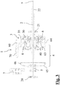
figure 3 shows a partially exploded cross-sectional view of the motor assembly offigure 2 ; -
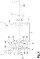
figure 4 shows a partially exploded cross-sectional view of the motor assembly offigure 2 ; -
figure 5 shows a cross-sectional view of the motor assemblyfigure 2 ; -
figure 6 shows a perspective view of a motor assembly according to a second embodiment of the present invention; -
figure 7 shows a partially exploded perspective view of the motor assembly offigure 6 ; -
figure 8 shows a cross-sectional view of the motor assembly offigure 6 . - With reference to the enclosed
figures 1-5 , a first embodiment of a motor assembly of a clothes dryer machine 1001 is generically indicated byreference number 1. - The
clothes dryer machine 100 as a whole is schematically represented infigure 1 . - Inside the machine at least one air path intercepted by an
air movement fan 103 is defined, which is keyed on a drivingshaft 2 dragged in rotation by a firstelectric motor 3. - The
clothes dryer machine 100 further comprises arotating drum 101, which is rotatably mounted with respect to a frame of the machine and which is intended to house a load of laundry to be dried. Said rotating drum is connected to a secondelectric motor 4 by means of atransmission belt 102. - Thus, the
motor assembly 1 comprises a drivingshaft 2 having longitudinal axis x. It is rotatably associated with the frame of theclothes dryer machine 100 by means of twoball bearings serrations 22 for keying theair movement fan 103. - Between the two
ball bearings electric motor 3 and the secondelectric motor 4 are arranged. - The two
electric motors - Both of them have an internal stator, a first
internal stator 30 and a secondinternal stator 40, respectively, and an outer rotor, a firstouter rotor 35 and a secondouter rotor 45, respectively. - The
internal stator electric motors section arms arms - The
outer rotor electric motors inner stator permanent magnet internal stator - It should be noted that, even if in the present embodiments the two
electric motors - The
internal stators electric motors main body 6, which is rotatably mounted above a portion of the drivingshaft 2 that is intermediate to the twoaforementioned ball bearings - The portion of the
main body 6 which supports the twointernal stators sleeve 62, which is in turn supported by the drivingshaft 2 having interposed ball bearings. - From the sleeve 62 a
central baffle 63, which connects it to a cylindricalperipheral wall 64, coaxial to thesleeve 62 itself, develops radially. The cylindricperipheral wall 64 is covered, at its opposite ends, by the cup of theouter rotors - Thus, a containment casing is defined, which encloses, in addition to the two
internal stators control board 8 attached to thecentral baffle 63, in the present application example on the side of the firstelectric motor 3. - The
control board 8, arranged to serve bothelectric motors power input 9a and to asignal input 9b which open on theperipheral wall 64. - The
central body 6 also comprises aneccentric portion 60, which protrudes laterally with respect to theperipheral wall 64. This portion supports a fixedpin 70, whereon anidler pulley 7 is mounted idle by interposition of two ball bearings. - Still on the
eccentric portion 60 anattachment 61 for a connection spring to the frame of theclothes dryer machine 100 is provided, to allow a floating connection mode which is traditionally used to constrain the actuating electric motors in the prior art machines. - The first
outer rotor 35 is directly keyed on the drivingshaft 2, so that the rotation of the firstelectric motor 3 drags in rotation the fan keyed on theserrations 22. - Instead the second
outer rotor 45 is rotatably mounted on the drivingshaft 2 by means of ball bearings. It has a tubular appendix away from the secondinternal stator 30, namely protruding with respect to the convex part of the rotor cup. The tubular appendix defines apulley 5 and has a plurality of transmission throats whereon thetransmission belt 102 to therotating drum 101 wounds. - With reference to the enclosed
figures 5-8 , a second embodiment of a motor assembly of aclothes dryer machine 100 is generically indicated with reference number 1'. - Said embodiment is substantially identical to the previous one, to the description of which reference is made, except for the control mode of the two
electric motors - Therefore, in this case, the
control board 8 is missing and replaced by two small connection boards 8'a, 8'b, each of which is intended to receive the power supply directed to the windings. - The connection boards 8'a, 8'b are arranged on the two sides of the
central baffle 63, from the side of theelectric motor - Obviously, a skilled person can make several changes and variants to the above described mechanical assembly and the appliance, in order to meet contingent and specific needs, all of them by the way contained in the scope of protection of the invention as defined by the following claims.
Claims (15)
- Motor assembly (1; 1') for a clothes dryer machine (100), comprising: a driving shaft (2) which is associable in a rotating manner with a frame of a clothes dryer machine (100) and arranged to drag in rotation an air movement fan (103) of said clothes dryer machine (100); a first electric motor (3) comprising a first internal stator (30) crossed by said driving shaft (2) and rotating relative thereto and a first outer rotor (35) integral in rotation with said driving shaft (2); characterized in that said motor assembly (1) also comprises a second electric motor (4) comprising in turn a second internal stator (40) and a second outer rotor (45), both crossed by said driving shaft (2) and rotating relative thereto, wherein said second outer rotor (45) is integral with a pulley (5) for actuating a drum (101) of said clothes dryer machine (100).
- Motor assembly (1; 1') according to claim 1, further comprising a main body (6), wherein the first internal stator (30) and the second internal stator (40) are both integral with said main body (6), said main body (6) being arranged to be mounted tilting with respect to the frame of said clothes dryer machine (100).
- Motor assembly (1; 1') according to claim 2, wherein said first internal stator (30) and said second internal stator (40) face two opposite ends of said main body (6), said first outer rotor (35) and said second outer rotor (45) being cup-shaped and closing said two opposite ends of the main body (6).
- Motor assembly (1; 1') according to one of claims 2 or 3, further comprising an idler pulley (7) rotatably mounted on a pin (70) integral with said main body (6), said idler pulley (7) being arranged axially in line with said pulley (5) along a longitudinal axis (x) of said driving shaft (2).
- Motor assembly (1; 1') according to claim 4, wherein said pin (70) is mounted parallel to the longitudinal axis (x) on an eccentric portion (60) of said main body (6), said eccentric portion (60) also providing an attachment (61) for a connection spring to the frame of the clothes dryer machine (100).
- Motor assembly (1; 1') according to one of claims 2-5, wherein said main body (6) comprises a sleeve (62) rotatably coupled above the driving shaft (2), said first internal stator (30) and said second internal stator (40) being both supported by said sleeve (62).
- Motor assembly (1; 1') according to claim 6, wherein said sleeve (62) is rotatably coupled to said driving shaft (2) by means of at least two interposed ball bearings.
- Motor assembly (1; 1') according to one of claims 6 or 7, wherein said main body (6) defines a housing casing for one or more connection and/or control boards (8; 8'a, 8'b) of the first and of the second electric motor (3, 4).
- Motor assembly (1; 1') according to claim 8, wherein said housing casing is defined by a peripheral wall (64) connected to the sleeve (62) by a central baffle (63) which is orthogonal to the longitudinal axis (x) of the driving shaft (2).
- Motor assembly (1; 1') according to any one of the previous claims, wherein said first outer rotor (35) and said second outer rotor (45) both comprise an annual permanent magnet (36, 46).
- Motor assembly (1; 1') according to any one of the previous claims, wherein said first internal stator (30) and said second internal stator (40) both comprise a pack of laminations made of ferromagnetic material, said pack of laminations having an annular core from which a plurality of arms (31, 41) departs out, said arms being covered by spools, on said spools electric windings being disposed.
- Motor assembly (1; 1') according to any one of the previous claims, wherein the second outer rotor (45) and the pulley (5) are made as a single piece, said piece being rotatably mounted above said driving shaft (2) with the interposition of at least one bearing.
- Motor assembly (1) according to any one of the previous claims, comprising a single power input (9a), a single signal input (9b) and a single control board (8) for both the first electric motor (3) and the second electric motor (4).
- Motor assembly (1') according to one of claims 1-13, wherein the control of the first electric motor (3) and of the second electric motor (4) is performed by a unit external to the motor assembly (1'), said motor assembly (1') comprising a first connection board (8'a) and a second connection board (8'b) which are dedicated to the first (3) and to the second electric motor (4), respectively.
- Clothes dryer machine (100) comprising: a rotating drum (101), rotatably mounted with respect to a frame and intended to house laundry to be dried; and at least one air movement fan (103), said clothes dryer machine (100) comprising a motor assembly (1; 1') according to any one of the previous claims.
Priority Applications (4)
| Application Number | Priority Date | Filing Date | Title |
|---|---|---|---|
| PT211563770T PT3836371T (en) | 2018-12-05 | 2018-12-05 | Enhanced motor assembly for clothes dryer machine and clothes dryer machine comprising said assembly |
| EP21156377.0A EP3836371B1 (en) | 2018-12-05 | 2018-12-05 | Enhanced motor assembly for clothes dryer machine and clothes dryer machine comprising said assembly |
| PL21156377.0T PL3836371T3 (en) | 2018-12-05 | 2018-12-05 | IMPROVED CLOTHES DRYER MOTOR ASSEMBLY AND A CLOTHES DRYER INCLUDING SAID MOTOR ASSEMBLY |
| ES21156377T ES3042397T3 (en) | 2018-12-05 | 2018-12-05 | Enhanced motor assembly for clothes dryer machine and clothes dryer machine comprising said assembly |
Applications Claiming Priority (2)
| Application Number | Priority Date | Filing Date | Title |
|---|---|---|---|
| EP18425094.2A EP3474429B1 (en) | 2018-12-05 | 2018-12-05 | Enhanced motor assembly for clothes dryer machine and clothes dryer machine comprising said assembly |
| EP21156377.0A EP3836371B1 (en) | 2018-12-05 | 2018-12-05 | Enhanced motor assembly for clothes dryer machine and clothes dryer machine comprising said assembly |
Related Parent Applications (2)
| Application Number | Title | Priority Date | Filing Date |
|---|---|---|---|
| EP18425094.2A Division-Into EP3474429B1 (en) | 2018-12-05 | 2018-12-05 | Enhanced motor assembly for clothes dryer machine and clothes dryer machine comprising said assembly |
| EP18425094.2A Division EP3474429B1 (en) | 2018-12-05 | 2018-12-05 | Enhanced motor assembly for clothes dryer machine and clothes dryer machine comprising said assembly |
Publications (2)
| Publication Number | Publication Date |
|---|---|
| EP3836371A1 true EP3836371A1 (en) | 2021-06-16 |
| EP3836371B1 EP3836371B1 (en) | 2025-09-10 |
Family
ID=65234383
Family Applications (3)
| Application Number | Title | Priority Date | Filing Date |
|---|---|---|---|
| EP18425094.2A Active EP3474429B1 (en) | 2018-12-05 | 2018-12-05 | Enhanced motor assembly for clothes dryer machine and clothes dryer machine comprising said assembly |
| EP21156377.0A Active EP3836371B1 (en) | 2018-12-05 | 2018-12-05 | Enhanced motor assembly for clothes dryer machine and clothes dryer machine comprising said assembly |
| EP19213761.0A Withdrawn EP3664265A1 (en) | 2018-12-05 | 2019-12-05 | Enhanced motor assembly for clothes dryer machine and clothes dryer machine comprising said assembly |
Family Applications Before (1)
| Application Number | Title | Priority Date | Filing Date |
|---|---|---|---|
| EP18425094.2A Active EP3474429B1 (en) | 2018-12-05 | 2018-12-05 | Enhanced motor assembly for clothes dryer machine and clothes dryer machine comprising said assembly |
Family Applications After (1)
| Application Number | Title | Priority Date | Filing Date |
|---|---|---|---|
| EP19213761.0A Withdrawn EP3664265A1 (en) | 2018-12-05 | 2019-12-05 | Enhanced motor assembly for clothes dryer machine and clothes dryer machine comprising said assembly |
Country Status (7)
| Country | Link |
|---|---|
| US (1) | US11165321B2 (en) |
| EP (3) | EP3474429B1 (en) |
| KR (1) | KR102732717B1 (en) |
| CN (1) | CN111270496B (en) |
| ES (2) | ES3042397T3 (en) |
| PL (2) | PL3474429T3 (en) |
| PT (2) | PT3474429T (en) |
Families Citing this family (9)
| Publication number | Priority date | Publication date | Assignee | Title |
|---|---|---|---|---|
| US11365509B2 (en) | 2019-10-01 | 2022-06-21 | Whirlpool Corporation | Dual motor dryer drive contained within a common assembly |
| CN110983732A (en) * | 2019-12-12 | 2020-04-10 | 青岛海尔滚筒洗衣机有限公司 | Dryer drive and dryer |
| KR102495021B1 (en) | 2020-11-04 | 2023-02-06 | 엘지전자 주식회사 | Drying apparatus and driving device for the same |
| CN112531998B (en) * | 2020-12-09 | 2025-09-26 | 美的威灵电机技术(上海)有限公司 | Power components and fans |
| KR102757411B1 (en) * | 2021-04-21 | 2025-01-21 | 엘지전자 주식회사 | Laundry Treatment Apparatus |
| CN114875646B (en) * | 2022-05-10 | 2023-10-24 | 安徽金帅洗衣机有限公司 | Clothes dryer based on double-motor driving |
| EP4442896A1 (en) | 2023-04-03 | 2024-10-09 | Arçelik Anonim Sirketi | A laundry dryer |
| WO2025139585A1 (en) * | 2023-12-29 | 2025-07-03 | 无锡小天鹅电器有限公司 | Clothes treatment device and clothes treatment device control method |
| CN120719516A (en) * | 2024-03-29 | 2025-09-30 | 无锡小天鹅电器有限公司 | Control method and device for clothes processing equipment and clothes processing equipment |
Citations (5)
| Publication number | Priority date | Publication date | Assignee | Title |
|---|---|---|---|---|
| CN1165654C (en) | 1998-06-12 | 2004-09-08 | 东芝株式会社 | clothes dryer |
| EP1696537A1 (en) * | 2005-02-25 | 2006-08-30 | Askoll Holding S.r.l. | Synchronous electric motor structure, particularly for washing machines with a rotary drum kinematically connected to the motor through a belt and pulley link |
| EP1860229A1 (en) | 2006-05-25 | 2007-11-28 | Electrolux Home Products Corporation N.V. | Household clothes drying machine with compact motor |
| EP2395144A2 (en) | 2011-09-14 | 2011-12-14 | V-Zug AG | Electric drive for domestic appliance |
| EP2447407A2 (en) * | 2010-10-28 | 2012-05-02 | Panasonic Corporation | Drum-type washing machine |
Family Cites Families (15)
| Publication number | Priority date | Publication date | Assignee | Title |
|---|---|---|---|---|
| DE19547456A1 (en) * | 1995-12-19 | 1997-06-26 | Bosch Siemens Hausgeraete | Drive device for a washing machine that can be loaded from the front |
| DE19636705C2 (en) * | 1996-09-10 | 1998-10-08 | Miele & Cie | Motor unit for a clothes dryer |
| KR100662770B1 (en) * | 2001-01-20 | 2007-01-02 | 주식회사 엘지이아이 | Motor mounting device of the clothes dryer |
| US6745495B1 (en) * | 2003-06-27 | 2004-06-08 | General Electric Company | Clothes dryer apparatus and method |
| CA2434354C (en) * | 2003-07-03 | 2008-10-14 | Camco Inc. | Clothes dryer with self speed regulated motor |
| KR100480927B1 (en) * | 2003-08-12 | 2005-04-07 | 엘지전자 주식회사 | Motor-fixing structure in clothing drier |
| US20050113216A1 (en) * | 2003-10-07 | 2005-05-26 | Wei Cheng | Belt drive system with outer rotor motor |
| ITPN20060053A1 (en) * | 2006-06-23 | 2007-12-24 | Appliances Components Companies Spa | INTEGRATED GROUP OF ELECTRIC MOTORS |
| EP2366827B1 (en) * | 2010-03-18 | 2013-01-02 | Askoll Holding S.r.l. | Motor/fans assembly for condenser clothes dryer and condenser clothes dryer comprising said assembly |
| EP2487290B1 (en) * | 2011-02-10 | 2014-05-07 | Electrolux Home Products Corporation N.V. | Home laundry drier |
| US9186799B2 (en) * | 2011-07-13 | 2015-11-17 | Brooks Automation, Inc. | Compact direct drive spindle |
| CN203212887U (en) * | 2013-04-07 | 2013-09-25 | 海尔集团公司 | Clothes dryer |
| WO2015155681A1 (en) * | 2014-04-08 | 2015-10-15 | Aaco Manufacturing S.R.L. | Electric drive unit provided with drive outlets that are operable independently to each other |
| ES2918901T3 (en) * | 2014-10-23 | 2022-07-21 | Magswitch Tech Inc | Brushless Slotless DC Motor/Actuator |
| CN207775572U (en) * | 2017-11-06 | 2018-08-28 | 青岛海尔洗衣机有限公司 | A kind of dryer |
-
2018
- 2018-12-05 EP EP18425094.2A patent/EP3474429B1/en active Active
- 2018-12-05 PT PT184250942T patent/PT3474429T/en unknown
- 2018-12-05 PL PL18425094T patent/PL3474429T3/en unknown
- 2018-12-05 EP EP21156377.0A patent/EP3836371B1/en active Active
- 2018-12-05 ES ES21156377T patent/ES3042397T3/en active Active
- 2018-12-05 PL PL21156377.0T patent/PL3836371T3/en unknown
- 2018-12-05 ES ES18425094T patent/ES2878301T3/en active Active
- 2018-12-05 PT PT211563770T patent/PT3836371T/en unknown
-
2019
- 2019-05-08 US US16/406,586 patent/US11165321B2/en active Active
- 2019-06-06 CN CN201910491051.1A patent/CN111270496B/en active Active
- 2019-06-07 KR KR1020190067406A patent/KR102732717B1/en active Active
- 2019-12-05 EP EP19213761.0A patent/EP3664265A1/en not_active Withdrawn
Patent Citations (5)
| Publication number | Priority date | Publication date | Assignee | Title |
|---|---|---|---|---|
| CN1165654C (en) | 1998-06-12 | 2004-09-08 | 东芝株式会社 | clothes dryer |
| EP1696537A1 (en) * | 2005-02-25 | 2006-08-30 | Askoll Holding S.r.l. | Synchronous electric motor structure, particularly for washing machines with a rotary drum kinematically connected to the motor through a belt and pulley link |
| EP1860229A1 (en) | 2006-05-25 | 2007-11-28 | Electrolux Home Products Corporation N.V. | Household clothes drying machine with compact motor |
| EP2447407A2 (en) * | 2010-10-28 | 2012-05-02 | Panasonic Corporation | Drum-type washing machine |
| EP2395144A2 (en) | 2011-09-14 | 2011-12-14 | V-Zug AG | Electric drive for domestic appliance |
Also Published As
| Publication number | Publication date |
|---|---|
| PT3836371T (en) | 2025-10-17 |
| PL3474429T3 (en) | 2021-11-02 |
| CN111270496A (en) | 2020-06-12 |
| US11165321B2 (en) | 2021-11-02 |
| US20200181829A1 (en) | 2020-06-11 |
| EP3474429A1 (en) | 2019-04-24 |
| PL3836371T3 (en) | 2025-11-24 |
| ES3042397T3 (en) | 2025-11-20 |
| EP3474429B1 (en) | 2021-03-24 |
| KR20200069204A (en) | 2020-06-16 |
| EP3664265A1 (en) | 2020-06-10 |
| EP3836371B1 (en) | 2025-09-10 |
| KR102732717B1 (en) | 2024-11-20 |
| CN111270496B (en) | 2024-06-18 |
| ES2878301T3 (en) | 2021-11-18 |
| PT3474429T (en) | 2021-05-26 |
Similar Documents
| Publication | Publication Date | Title |
|---|---|---|
| EP3836371B1 (en) | Enhanced motor assembly for clothes dryer machine and clothes dryer machine comprising said assembly | |
| US5862686A (en) | Drive device for a front-loading washing machine | |
| US11807980B2 (en) | Dual motor dryer drive contained within a common assembly | |
| EP2366827A1 (en) | Motor/fans assembly for condenser clothes dryer and condenser clothes dryer comprising said assembly | |
| JP2007061625A (en) | Washing machine | |
| KR100682661B1 (en) | A motor and a washing machine including the motor | |
| US12381439B2 (en) | Direct-drive, axially flux oriented, electric motor assembly having primary heat conduction pathway from stator to bearing housing | |
| KR100616165B1 (en) | Rotor of motor for drum washing machine | |
| EP1836340B1 (en) | A washer / dryer | |
| JP2011056138A (en) | Rotary electric machine for driving blowing fan of clothes drier | |
| EP1795641A1 (en) | Household-type clothes washing machine with compact drive motor | |
| KR101934290B1 (en) | Washing machine | |
| WO2016102030A1 (en) | Electric machine with improved assembly | |
| EP2112261B1 (en) | Household-type clothes washing machine with improved washing tub | |
| EP1607506A1 (en) | Drum-type washing machine with an outer rotor type motor |
Legal Events
| Date | Code | Title | Description |
|---|---|---|---|
| PUAI | Public reference made under article 153(3) epc to a published international application that has entered the european phase |
Free format text: ORIGINAL CODE: 0009012 |
|
| STAA | Information on the status of an ep patent application or granted ep patent |
Free format text: STATUS: THE APPLICATION HAS BEEN PUBLISHED |
|
| AC | Divisional application: reference to earlier application |
Ref document number: 3474429 Country of ref document: EP Kind code of ref document: P |
|
| AK | Designated contracting states |
Kind code of ref document: A1 Designated state(s): AL AT BE BG CH CY CZ DE DK EE ES FI FR GB GR HR HU IE IS IT LI LT LU LV MC MK MT NL NO PL PT RO RS SE SI SK SM TR |
|
| STAA | Information on the status of an ep patent application or granted ep patent |
Free format text: STATUS: REQUEST FOR EXAMINATION WAS MADE |
|
| 17P | Request for examination filed |
Effective date: 20211216 |
|
| RBV | Designated contracting states (corrected) |
Designated state(s): AL AT BE BG CH CY CZ DE DK EE ES FI FR GB GR HR HU IE IS IT LI LT LU LV MC MK MT NL NO PL PT RO RS SE SI SK SM TR |
|
| STAA | Information on the status of an ep patent application or granted ep patent |
Free format text: STATUS: EXAMINATION IS IN PROGRESS |
|
| 17Q | First examination report despatched |
Effective date: 20230421 |
|
| P01 | Opt-out of the competence of the unified patent court (upc) registered |
Effective date: 20230520 |
|
| GRAP | Despatch of communication of intention to grant a patent |
Free format text: ORIGINAL CODE: EPIDOSNIGR1 |
|
| STAA | Information on the status of an ep patent application or granted ep patent |
Free format text: STATUS: GRANT OF PATENT IS INTENDED |
|
| RIC1 | Information provided on ipc code assigned before grant |
Ipc: H02K 5/15 20060101ALN20250507BHEP Ipc: H02K 7/14 20060101ALN20250507BHEP Ipc: H02K 1/27 20060101ALN20250507BHEP Ipc: H02K 7/10 20060101ALI20250507BHEP Ipc: D06F 58/08 20060101ALI20250507BHEP Ipc: H02K 16/00 20060101AFI20250507BHEP |
|
| RIC1 | Information provided on ipc code assigned before grant |
Ipc: H02K 5/15 20060101ALN20250515BHEP Ipc: H02K 7/14 20060101ALN20250515BHEP Ipc: H02K 1/27 20060101ALN20250515BHEP Ipc: H02K 7/10 20060101ALI20250515BHEP Ipc: D06F 58/08 20060101ALI20250515BHEP Ipc: H02K 16/00 20060101AFI20250515BHEP |
|
| INTG | Intention to grant announced |
Effective date: 20250522 |
|
| GRAS | Grant fee paid |
Free format text: ORIGINAL CODE: EPIDOSNIGR3 |
|
| GRAA | (expected) grant |
Free format text: ORIGINAL CODE: 0009210 |
|
| STAA | Information on the status of an ep patent application or granted ep patent |
Free format text: STATUS: THE PATENT HAS BEEN GRANTED |
|
| AC | Divisional application: reference to earlier application |
Ref document number: 3474429 Country of ref document: EP Kind code of ref document: P |
|
| AK | Designated contracting states |
Kind code of ref document: B1 Designated state(s): AL AT BE BG CH CY CZ DE DK EE ES FI FR GB GR HR HU IE IS IT LI LT LU LV MC MK MT NL NO PL PT RO RS SE SI SK SM TR |
|
| REG | Reference to a national code |
Ref country code: GB Ref legal event code: FG4D |
|
| REG | Reference to a national code |
Ref country code: CH Ref legal event code: EP |
|
| REG | Reference to a national code |
Ref country code: DE Ref legal event code: R096 Ref document number: 602018085576 Country of ref document: DE |
|
| REG | Reference to a national code |
Ref country code: CH Ref legal event code: R17 Free format text: ST27 STATUS EVENT CODE: U-0-0-R10-R17 (AS PROVIDED BY THE NATIONAL OFFICE) Effective date: 20251007 |
|
| REG | Reference to a national code |
Ref country code: IE Ref legal event code: FG4D |
|
| REG | Reference to a national code |
Ref country code: SE Ref legal event code: TRGR |
|
| REG | Reference to a national code |
Ref country code: PT Ref legal event code: SC4A Ref document number: 3836371 Country of ref document: PT Date of ref document: 20251017 Kind code of ref document: T Free format text: AVAILABILITY OF NATIONAL TRANSLATION Effective date: 20251010 |
|
| REG | Reference to a national code |
Ref country code: ES Ref legal event code: FG2A Ref document number: 3042397 Country of ref document: ES Kind code of ref document: T3 Effective date: 20251120 |
|
| REG | Reference to a national code |
Ref country code: SK Ref legal event code: T3 Ref document number: E 47277 Country of ref document: SK |
|
| PGFP | Annual fee paid to national office [announced via postgrant information from national office to epo] |
Ref country code: PT Payment date: 20251121 Year of fee payment: 8 |
|
| REG | Reference to a national code |
Ref country code: CH Ref legal event code: U11 Free format text: ST27 STATUS EVENT CODE: U-0-0-U10-U11 (AS PROVIDED BY THE NATIONAL OFFICE) Effective date: 20260101 |
|
| PGFP | Annual fee paid to national office [announced via postgrant information from national office to epo] |
Ref country code: DE Payment date: 20251126 Year of fee payment: 8 |
|
| PGFP | Annual fee paid to national office [announced via postgrant information from national office to epo] |
Ref country code: GB Payment date: 20251119 Year of fee payment: 8 |
|
| PG25 | Lapsed in a contracting state [announced via postgrant information from national office to epo] |
Ref country code: NO Free format text: LAPSE BECAUSE OF FAILURE TO SUBMIT A TRANSLATION OF THE DESCRIPTION OR TO PAY THE FEE WITHIN THE PRESCRIBED TIME-LIMIT Effective date: 20251210 |
|
| REG | Reference to a national code |
Ref country code: LT Ref legal event code: MG9D |
|
| PGFP | Annual fee paid to national office [announced via postgrant information from national office to epo] |
Ref country code: AT Payment date: 20251121 Year of fee payment: 8 |
|
| PG25 | Lapsed in a contracting state [announced via postgrant information from national office to epo] |
Ref country code: FI Free format text: LAPSE BECAUSE OF FAILURE TO SUBMIT A TRANSLATION OF THE DESCRIPTION OR TO PAY THE FEE WITHIN THE PRESCRIBED TIME-LIMIT Effective date: 20250910 |
|
| PGFP | Annual fee paid to national office [announced via postgrant information from national office to epo] |
Ref country code: IT Payment date: 20251119 Year of fee payment: 8 |
|
| REG | Reference to a national code |
Ref country code: NL Ref legal event code: MP Effective date: 20250910 |
|
| PG25 | Lapsed in a contracting state [announced via postgrant information from national office to epo] |
Ref country code: HR Free format text: LAPSE BECAUSE OF FAILURE TO SUBMIT A TRANSLATION OF THE DESCRIPTION OR TO PAY THE FEE WITHIN THE PRESCRIBED TIME-LIMIT Effective date: 20250910 |
|
| PGFP | Annual fee paid to national office [announced via postgrant information from national office to epo] |
Ref country code: FR Payment date: 20251119 Year of fee payment: 8 |
|
| PG25 | Lapsed in a contracting state [announced via postgrant information from national office to epo] |
Ref country code: GR Free format text: LAPSE BECAUSE OF FAILURE TO SUBMIT A TRANSLATION OF THE DESCRIPTION OR TO PAY THE FEE WITHIN THE PRESCRIBED TIME-LIMIT Effective date: 20251211 |
|
| PGFP | Annual fee paid to national office [announced via postgrant information from national office to epo] |
Ref country code: TR Payment date: 20251126 Year of fee payment: 8 Ref country code: BE Payment date: 20251119 Year of fee payment: 8 |
|
| PGFP | Annual fee paid to national office [announced via postgrant information from national office to epo] |
Ref country code: SE Payment date: 20251119 Year of fee payment: 8 |
|
| PGFP | Annual fee paid to national office [announced via postgrant information from national office to epo] |
Ref country code: CZ Payment date: 20251204 Year of fee payment: 8 |
|
| PG25 | Lapsed in a contracting state [announced via postgrant information from national office to epo] |
Ref country code: LV Free format text: LAPSE BECAUSE OF FAILURE TO SUBMIT A TRANSLATION OF THE DESCRIPTION OR TO PAY THE FEE WITHIN THE PRESCRIBED TIME-LIMIT Effective date: 20250910 |
|
| PG25 | Lapsed in a contracting state [announced via postgrant information from national office to epo] |
Ref country code: BG Free format text: LAPSE BECAUSE OF FAILURE TO SUBMIT A TRANSLATION OF THE DESCRIPTION OR TO PAY THE FEE WITHIN THE PRESCRIBED TIME-LIMIT Effective date: 20250910 |
|
| PGFP | Annual fee paid to national office [announced via postgrant information from national office to epo] |
Ref country code: PL Payment date: 20251124 Year of fee payment: 8 |
|
| PGFP | Annual fee paid to national office [announced via postgrant information from national office to epo] |
Ref country code: SK Payment date: 20251124 Year of fee payment: 8 Ref country code: RO Payment date: 20251203 Year of fee payment: 8 |
|
| PG25 | Lapsed in a contracting state [announced via postgrant information from national office to epo] |
Ref country code: RS Free format text: LAPSE BECAUSE OF FAILURE TO SUBMIT A TRANSLATION OF THE DESCRIPTION OR TO PAY THE FEE WITHIN THE PRESCRIBED TIME-LIMIT Effective date: 20251210 |
|
| PG25 | Lapsed in a contracting state [announced via postgrant information from national office to epo] |
Ref country code: NL Free format text: LAPSE BECAUSE OF FAILURE TO SUBMIT A TRANSLATION OF THE DESCRIPTION OR TO PAY THE FEE WITHIN THE PRESCRIBED TIME-LIMIT Effective date: 20250910 |
|
| PG25 | Lapsed in a contracting state [announced via postgrant information from national office to epo] |
Ref country code: SM Free format text: LAPSE BECAUSE OF FAILURE TO SUBMIT A TRANSLATION OF THE DESCRIPTION OR TO PAY THE FEE WITHIN THE PRESCRIBED TIME-LIMIT Effective date: 20250910 |
|
| PGFP | Annual fee paid to national office [announced via postgrant information from national office to epo] |
Ref country code: ES Payment date: 20260102 Year of fee payment: 8 |
|
| PG25 | Lapsed in a contracting state [announced via postgrant information from national office to epo] |
Ref country code: IS Free format text: LAPSE BECAUSE OF FAILURE TO SUBMIT A TRANSLATION OF THE DESCRIPTION OR TO PAY THE FEE WITHIN THE PRESCRIBED TIME-LIMIT Effective date: 20260110 |
|
| PGFP | Annual fee paid to national office [announced via postgrant information from national office to epo] |
Ref country code: CH Payment date: 20260101 Year of fee payment: 8 |
|
| PG25 | Lapsed in a contracting state [announced via postgrant information from national office to epo] |
Ref country code: EE Free format text: LAPSE BECAUSE OF FAILURE TO SUBMIT A TRANSLATION OF THE DESCRIPTION OR TO PAY THE FEE WITHIN THE PRESCRIBED TIME-LIMIT Effective date: 20250910 |