EP3836367A1 - Vehicular motor drive unit - Google Patents
Vehicular motor drive unit Download PDFInfo
- Publication number
- EP3836367A1 EP3836367A1 EP19848363.8A EP19848363A EP3836367A1 EP 3836367 A1 EP3836367 A1 EP 3836367A1 EP 19848363 A EP19848363 A EP 19848363A EP 3836367 A1 EP3836367 A1 EP 3836367A1
- Authority
- EP
- European Patent Office
- Prior art keywords
- case portion
- cable
- partition part
- axial direction
- space
- Prior art date
- Legal status (The legal status is an assumption and is not a legal conclusion. Google has not performed a legal analysis and makes no representation as to the accuracy of the status listed.)
- Withdrawn
Links
- 238000005192 partition Methods 0.000 claims abstract description 78
- 239000003638 chemical reducing agent Substances 0.000 claims description 46
- 239000003921 oil Substances 0.000 claims description 33
- 238000004873 anchoring Methods 0.000 claims description 16
- 239000010687 lubricating oil Substances 0.000 claims description 12
- 238000000034 method Methods 0.000 description 24
- 230000002093 peripheral effect Effects 0.000 description 16
- 230000008569 process Effects 0.000 description 14
- 230000008878 coupling Effects 0.000 description 6
- 238000010168 coupling process Methods 0.000 description 6
- 238000005859 coupling reaction Methods 0.000 description 6
- 238000005096 rolling process Methods 0.000 description 6
- 238000010586 diagram Methods 0.000 description 5
- 230000004048 modification Effects 0.000 description 5
- 238000012986 modification Methods 0.000 description 5
- 238000003780 insertion Methods 0.000 description 3
- 230000037431 insertion Effects 0.000 description 3
- 230000002452 interceptive effect Effects 0.000 description 2
- 230000000717 retained effect Effects 0.000 description 2
- 239000003566 sealing material Substances 0.000 description 2
- 229910000831 Steel Inorganic materials 0.000 description 1
- 239000000356 contaminant Substances 0.000 description 1
- 230000007547 defect Effects 0.000 description 1
- 238000001514 detection method Methods 0.000 description 1
- 239000000428 dust Substances 0.000 description 1
- 230000000694 effects Effects 0.000 description 1
- 230000002708 enhancing effect Effects 0.000 description 1
- 230000007246 mechanism Effects 0.000 description 1
- 230000000149 penetrating effect Effects 0.000 description 1
- 238000007789 sealing Methods 0.000 description 1
- 239000010959 steel Substances 0.000 description 1
- 239000013585 weight reducing agent Substances 0.000 description 1
Images



Classifications
-
- B—PERFORMING OPERATIONS; TRANSPORTING
- B60—VEHICLES IN GENERAL
- B60K—ARRANGEMENT OR MOUNTING OF PROPULSION UNITS OR OF TRANSMISSIONS IN VEHICLES; ARRANGEMENT OR MOUNTING OF PLURAL DIVERSE PRIME-MOVERS IN VEHICLES; AUXILIARY DRIVES FOR VEHICLES; INSTRUMENTATION OR DASHBOARDS FOR VEHICLES; ARRANGEMENTS IN CONNECTION WITH COOLING, AIR INTAKE, GAS EXHAUST OR FUEL SUPPLY OF PROPULSION UNITS IN VEHICLES
- B60K7/00—Disposition of motor in, or adjacent to, traction wheel
- B60K7/0007—Disposition of motor in, or adjacent to, traction wheel the motor being electric
-
- H—ELECTRICITY
- H02—GENERATION; CONVERSION OR DISTRIBUTION OF ELECTRIC POWER
- H02K—DYNAMO-ELECTRIC MACHINES
- H02K11/00—Structural association of dynamo-electric machines with electric components or with devices for shielding, monitoring or protection
- H02K11/20—Structural association of dynamo-electric machines with electric components or with devices for shielding, monitoring or protection for measuring, monitoring, testing, protecting or switching
- H02K11/21—Devices for sensing speed or position, or actuated thereby
-
- H—ELECTRICITY
- H02—GENERATION; CONVERSION OR DISTRIBUTION OF ELECTRIC POWER
- H02K—DYNAMO-ELECTRIC MACHINES
- H02K11/00—Structural association of dynamo-electric machines with electric components or with devices for shielding, monitoring or protection
- H02K11/20—Structural association of dynamo-electric machines with electric components or with devices for shielding, monitoring or protection for measuring, monitoring, testing, protecting or switching
- H02K11/21—Devices for sensing speed or position, or actuated thereby
- H02K11/225—Detecting coils
-
- H—ELECTRICITY
- H02—GENERATION; CONVERSION OR DISTRIBUTION OF ELECTRIC POWER
- H02K—DYNAMO-ELECTRIC MACHINES
- H02K11/00—Structural association of dynamo-electric machines with electric components or with devices for shielding, monitoring or protection
- H02K11/20—Structural association of dynamo-electric machines with electric components or with devices for shielding, monitoring or protection for measuring, monitoring, testing, protecting or switching
- H02K11/25—Devices for sensing temperature, or actuated thereby
-
- H—ELECTRICITY
- H02—GENERATION; CONVERSION OR DISTRIBUTION OF ELECTRIC POWER
- H02K—DYNAMO-ELECTRIC MACHINES
- H02K5/00—Casings; Enclosures; Supports
- H02K5/04—Casings or enclosures characterised by the shape, form or construction thereof
- H02K5/22—Auxiliary parts of casings not covered by groups H02K5/06-H02K5/20, e.g. shaped to form connection boxes or terminal boxes
- H02K5/225—Terminal boxes or connection arrangements
-
- H—ELECTRICITY
- H02—GENERATION; CONVERSION OR DISTRIBUTION OF ELECTRIC POWER
- H02K—DYNAMO-ELECTRIC MACHINES
- H02K7/00—Arrangements for handling mechanical energy structurally associated with dynamo-electric machines, e.g. structural association with mechanical driving motors or auxiliary dynamo-electric machines
- H02K7/10—Structural association with clutches, brakes, gears, pulleys or mechanical starters
- H02K7/116—Structural association with clutches, brakes, gears, pulleys or mechanical starters with gears
-
- H—ELECTRICITY
- H02—GENERATION; CONVERSION OR DISTRIBUTION OF ELECTRIC POWER
- H02K—DYNAMO-ELECTRIC MACHINES
- H02K9/00—Arrangements for cooling or ventilating
- H02K9/19—Arrangements for cooling or ventilating for machines with closed casing and closed-circuit cooling using a liquid cooling medium, e.g. oil
-
- B—PERFORMING OPERATIONS; TRANSPORTING
- B60—VEHICLES IN GENERAL
- B60K—ARRANGEMENT OR MOUNTING OF PROPULSION UNITS OR OF TRANSMISSIONS IN VEHICLES; ARRANGEMENT OR MOUNTING OF PLURAL DIVERSE PRIME-MOVERS IN VEHICLES; AUXILIARY DRIVES FOR VEHICLES; INSTRUMENTATION OR DASHBOARDS FOR VEHICLES; ARRANGEMENTS IN CONNECTION WITH COOLING, AIR INTAKE, GAS EXHAUST OR FUEL SUPPLY OF PROPULSION UNITS IN VEHICLES
- B60K7/00—Disposition of motor in, or adjacent to, traction wheel
- B60K2007/0038—Disposition of motor in, or adjacent to, traction wheel the motor moving together with the wheel axle
-
- B—PERFORMING OPERATIONS; TRANSPORTING
- B60—VEHICLES IN GENERAL
- B60K—ARRANGEMENT OR MOUNTING OF PROPULSION UNITS OR OF TRANSMISSIONS IN VEHICLES; ARRANGEMENT OR MOUNTING OF PLURAL DIVERSE PRIME-MOVERS IN VEHICLES; AUXILIARY DRIVES FOR VEHICLES; INSTRUMENTATION OR DASHBOARDS FOR VEHICLES; ARRANGEMENTS IN CONNECTION WITH COOLING, AIR INTAKE, GAS EXHAUST OR FUEL SUPPLY OF PROPULSION UNITS IN VEHICLES
- B60K7/00—Disposition of motor in, or adjacent to, traction wheel
- B60K2007/0061—Disposition of motor in, or adjacent to, traction wheel the motor axle being parallel to the wheel axle
-
- B—PERFORMING OPERATIONS; TRANSPORTING
- B60—VEHICLES IN GENERAL
- B60L—PROPULSION OF ELECTRICALLY-PROPELLED VEHICLES; SUPPLYING ELECTRIC POWER FOR AUXILIARY EQUIPMENT OF ELECTRICALLY-PROPELLED VEHICLES; ELECTRODYNAMIC BRAKE SYSTEMS FOR VEHICLES IN GENERAL; MAGNETIC SUSPENSION OR LEVITATION FOR VEHICLES; MONITORING OPERATING VARIABLES OF ELECTRICALLY-PROPELLED VEHICLES; ELECTRIC SAFETY DEVICES FOR ELECTRICALLY-PROPELLED VEHICLES
- B60L2220/00—Electrical machine types; Structures or applications thereof
- B60L2220/50—Structural details of electrical machines
-
- Y—GENERAL TAGGING OF NEW TECHNOLOGICAL DEVELOPMENTS; GENERAL TAGGING OF CROSS-SECTIONAL TECHNOLOGIES SPANNING OVER SEVERAL SECTIONS OF THE IPC; TECHNICAL SUBJECTS COVERED BY FORMER USPC CROSS-REFERENCE ART COLLECTIONS [XRACs] AND DIGESTS
- Y02—TECHNOLOGIES OR APPLICATIONS FOR MITIGATION OR ADAPTATION AGAINST CLIMATE CHANGE
- Y02T—CLIMATE CHANGE MITIGATION TECHNOLOGIES RELATED TO TRANSPORTATION
- Y02T10/00—Road transport of goods or passengers
- Y02T10/60—Other road transportation technologies with climate change mitigation effect
- Y02T10/64—Electric machine technologies in electromobility
Definitions
- the present invention relates to a motor drive device for vehicles, and particularly relates to a wiring structure of signal cables in a motor drive device for vehicles.
- Motor drive devices for vehicles include a casing that defines its enclosure, and a motor unit disposed within the casing. Inside the casing are arranged a power line for supplying electric power to the motor unit and a signal cable (signal line) for transmitting detection signals of various sensors to the vehicle body, and these cables are drawn out from the casing to the outside.
- a power line for supplying electric power to the motor unit
- a signal cable for transmitting detection signals of various sensors to the vehicle body
- an in-wheel motor drive device disposed in an inner hollow region (within the wheel) of the wheel is particularly required to be lightweight and compact as much as possible, due to the mountability to the vehicle and in terms of enhancing driving performance. Therefore, in order to dispose the various cables within the limited space without interfering with peripheral components, many thoughts have been given to the protection structure of the cables within the casing and the fixing structure for improving wire connection workability.
- Patent Document 1 discloses a structure that passes a power cable (power line) that supplies electric source to the motor unit through the inside of a motor support shaft. Moreover, as a method for improving workability of wire connection, use of a socket (connector) as in Japanese Unexamined Patent Publication No. 2016-068605 (Patent Document 2) is also broadly implemented.
- Patent Document 3 discloses a wire fixing structure for preventing cables from being pinched in an assembling process of a motor drive device for vehicles.
- the power line is not positioned and fixed at the point of closing the housing (side portion). Therefore, the wired state of the power line within the housing cannot be directly (visually) confirmed at the time of completing the assembling.
- a method can be considered in which the wired state of the power line is managed by the length of the wire from a wire inlet of a through hole of a motor shaft, however the tension applied on the cable within the housing and the bent state and clearance from the peripheral components will vary depending on the way the assembly work is performed.
- a signal cable of a revolution sensor attached and fixed to an inner edge surface of a rear cover is arranged in a radial and vertical direction along this inner end surface, and provides a fixing unit on a passage of this signal cable. Furthermore, the technique employs a housing structure that prevents the cable from being pinched at a position that becomes a blind spot when attaching the rear cover to an end portion of the motor casing in an axial direction. Therefore, the technique of Patent Document 3 can eliminate to the utmost degree the possibility of malfunctioning due to the signal cable wired state during assembly and after completion of the drive device.
- Patent Document 3 can only be applied to a wiring structure that arranges the signal cable of the sensor attached on the inner end surface of the rear cover in the radial direction, and that draws this signal cable to a terminal box positioned on an outer peripheral side of the motor casing. That is to say, in a motor drive device in which an external connector of the signal cable is provided for example on the rear cover, the technique of Patent Document 3 cannot be applied to the wiring structure of the signal cable from the sensor fixed to the motor casing or the reducer unit casing to the external connector. Therefore, even with such motor drive device, there has been a demand for a technique to improve the reliability of the wired state of the signal cable upon completion of the assembly.
- the present invention is accomplished to overcome the above problem, and an object thereof is to provide a motor drive device for vehicles that allows for improving the reliability of a wired state of the signal cable within the casing.
- a motor drive device for vehicles includes: a motor unit including a motor rotating shaft configured to drive a wheel; and a casing configured to partition a first space in which the motor unit is disposed and a second space positioned on one side in an axial direction of the first space, and including a partition part provided with a through hole configured to communicate the first and second spaces.
- the casing is divided into a cylindrical first case portion integrally formed with the partition part, a second case section being connected to one end of the first casing in the axial direction and covering the second space, and a third case portion connected to the other end of the first case portion in the axial direction and covering the first space.
- This motor drive device for vehicles includes: a sensor disposed within the casing; a signal cable extending from the sensor to an external connector provided in the second case portion or the third case portion and which is passed through the through hole of the partition part; and an anchoring unit.
- the anchoring unit anchors the signal cable to the first case portion in the vicinity of the through hole of the partition part.
- the external connector or a cable fixing member provided in the second case portion or the third case portion is disposed at a position facing the through hole of the partition part in the axial direction.
- the signal cable has a first cable extending from the external connector, and a second cable extending from the sensor side and being connected to the first cable.
- the first cable and the second cable are connected by an internal connector
- the anchoring unit preferably includes a connector fixing member that fixes the internal connector in the vicinity of the through hole of the partition part.
- the external connector is provided in the third case portion.
- the external connector or the cable fixing member to a tip of the internal connector preferably has a length in the axial direction not less than a length in the axial direction from the external connector or the cable fixing member to an end plane of the partition part on the second space side.
- the anchoring unit includes a play retaining member configured to retain a playing part of the first cable or the second cable in the vicinity of the through hole of the partition part.
- the first cable is connected to the sensor that is fixed to the first case portion.
- the signal cable may extend along the axial direction between an internal connector to which the sensor is integrally provided and the external connector.
- the anchoring unit preferably includes a connector fixing member configured to fix the internal connector in the vicinity of the through hole of the partition part.
- an oil tank configured to store lubricating oil is provided lower of the second space, and the through hole is an opening for returning lubricating oil from the first space to the oil tank in the second space.
- the motor drive device for vehicles further includes a reducer unit configured to reduce rotation of the motor rotating shaft, which is positioned in the second space.
- the reducer unit includes an input shaft coupled with one end of the motor rotating shaft in the axial direction and an output shaft disposed parallel to the input shaft.
- the through hole of the partition part is preferably provided at a position below shaft centers of the input shaft and the output shaft of the reducer unit.
- the motor drive device for vehicles is preferably an in-wheel motor drive device in which the casing is disposed in an inner hollow region of the wheel.
- the one side of the motor rotating shaft in the axial direction is an outer side in a vehicle width direction
- the other side of the motor rotating shaft in the axial direction is an inner side in the vehicle width direction.
- the wired state of the signal cables within the casing can be directly confirmed in the assembling process of the motor drive device for vehicles. Therefore, according to the present invention, it is possible to improve the reliability of the wired state of the signal cable within the casing.
- FIG. 1 and Fig. 2 is an example of a basic configuration of an in-wheel motor drive device 1 according to an embodiment of the present invention.
- the in-wheel motor drive device 1 is installed in passenger cars such as electric automobiles and hybrid vehicles.
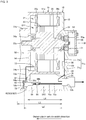
- Fig. 1 is a longitudinal section view cutting the in-wheel motor drive device 1 according to an embodiment of the present invention at a predefined plane, and illustrating this in a developed manner.
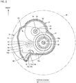
- Fig. 2 is a cross sectional view illustrating an inner structure of a reducer unit 31 of the in-wheel motor drive device 1, and schematically represents a state viewed from an outer side in a vehicle width direction.
- the predefined plane illustrated in Fig. 1 is a developed plan view connecting a plan view including an axis M and an axis N shown in Fig. 2 , and a plan view including the axis N and an axis O, in this order.
- Fig. 1 represents an outer side (outboard side) in the vehicle width direction, and a right side of printed Fig. 1 represents an inner side (inboard side) in the vehicle width direction.
- Fig. 2 each gear within the reducer unit 31 is represented by an addendum circle, and each individual tooth is omitted in the drawing.
- the in-wheel motor drive device 1 includes a wheel hub bearing unit 11 provided at the center of a wheel W, a motor unit 21 that drives the wheels, and a reducer unit 31 that reduces the rotation of the motor unit 21 and transmits this to the wheel hub bearing unit 11.
- the motor unit 21 and reducer unit 31 are disposed offset of the axis O of the wheel hub bearing unit 11.
- the axis O extends in the vehicle width direction, and is coaxial to the axle.
- the one side in the axis O direction is the outer side in the vehicle width direction
- the other side in the axis O direction is the inner side in the vehicle width direction.
- the wheel hub bearing unit 11 is disposed on one side of the in-wheel motor drive device 1 in the axis direction
- the motor unit 21 is disposed on the other side of the in-wheel motor drive device 1 in the axis direction
- the reducer unit 31 is disposed on the one side in the axis direction of the motor unit 21, and the position in the axis direction of the reducer unit 31 overlaps with the position in the axis direction of the wheel hub bearing unit 11.
- the in-wheel motor drive device 1 is a motor drive device for vehicles to drive wheels of an electric motor vehicle.
- the in-wheel motor drive device 1 is connected to a vehicle body not illustrated.
- the in-wheel motor drive device 1 can make the electric motor vehicle run at a speed of 0 to 180 km/h.
- the in-wheel motor drive device 1 includes a casing 10 that defines its enclosure.
- a direction along an axis M direction of the motor unit 21 (axis O direction of the reducer unit 31) is also called an axial direction.
- a direction orthogonal to the axis M direction is called a radial direction.
- the casing 10 includes a partition part 54 that partitions in the axial direction a first space S1 in which the motor unit 21 is disposed and a second space S2 in which the reducer unit 31 is disposed.
- the partition part 54 extends in the radial direction, and has an insertion hole 54a through which one end of the motor rotating shaft 22 in the axis M direction is inserted.
- the casing 10 is divided into three case portions 51, 52, and 53 along the axial direction.
- the first case portion 51 is a cylindrical case portion with the partition part 54 in an integrated manner.
- the first case portion 51 has a part 51a located on the other side in the axial direction (inner side of the vehicle width direction) of the partition part 54 and a part 51b located on the one side in the axial direction (outer side of the vehicle width direction) of the partition part 54.
- the partition part 54 is disposed offset to one side in the axial direction from a center position of the first case portion 51 in the axial direction. Therefore, the first case portion 51 mainly functions as a motor casing that surrounds the first space S1.
- the part 51a surrounding the first space S1 side is called body part 51a
- the part 51b surrounding the first space S1 side is called protruding part 51b.
- the second case portion 52 is connected to the one end of the first case portion 51 in the axial direction and covers the second space S2.
- the second case portion 52 includes a cylindrical portion 52t that abuts an end plane of the protruding part 51b of the first case portion 51, and a wall portion 52f of a plate form that closes the one end of the cylindrical portion 52t in the axial direction.
- the second case portion 52 mainly functions as a reducer unit casing that surrounds the second space S2.
- the third case portion 53 is connected to the other end of the first case portion 51 in the axial direction, and covers the first space S1.
- the third case portion 53 is a lid of the first case portion 51, and functions as a rear cover (motor casing cover).
- the third case portion 53 is shaped as a bowl for example, and includes a cylindrical portion 53t that abuts an end plane of the body part 51a of the first case portion 51, and a wall portion 53r of a plate shape that closes the other end of the cylindrical portion 53t in the axial direction.
- the motor unit 21 is covered from the one side in the axial direction by the partition part 54, and is covered from the other side in the axial direction by the wall portion 53r.
- the reducer unit 31 is covered from the one side in the axial direction by the wall portion 52f of the second case portion 52, and is covered from the other side in the axial direction by the partition part 54.
- the wall portion 52f of the second case portion 52 defines an outer side end plane of the casing 10 in the vehicle width direction
- the wall portion 53r of the third case portion 53 defines an inner side end plane of the casing 10 in the vehicle width direction.
- the first space S1 including a motor chamber is divided by a cylindrical portion defined by the body part 51a of the first case portion 51 and the cylindrical portion 53t of the third case portion 53, and by the partition part 54 and the wall portion 53r that intersect with this cylindrical portion.
- the second space S2 including a reducer chamber is divided by a cylindrical portion defined by the cylindrical portion 52t of the second case portion 52 and the protruding part 51b of the first case portion 51, and by the partition part 54 and the wall portion 53f that intersect with this cylindrical portion.
- the wheel hub bearing unit 11 is deemed as a rotating inner ring / stationary outer ring, and has an inner ring 12 as a rotating ring (hub ring) that couples with the wheel W, an outer ring 13 as a stationary ring disposed coaxially to an outside diameter side of the inner ring 12, and a plurality of rolling elements 14 disposed in an annular space between the inner ring 12 and the outer ring 13.
- the center of rotation of the inner ring 12 matches with the axis O passing through the center of the wheel hub bearing unit 11.
- the outer ring 13 penetrates through the wall portion 52f of the casing 10 (second case portion 52), and is connected and fixed to this wall portion 52f.
- a plurality of outer ring protrusions that protrude in an outer radial direction are provided upright at various positions in a circumferential direction on an outer peripheral surface of the outer ring 13, and bolts are passed through from the one side in the axis O direction to the through holes provided to each of the outer ring protrusions.
- Shank portions of the bolts screw together with a female screw drilled in the wall portion 52f of the casing 10.
- the outer ring 13 has a carrier member 61 connected and fixed thereto.
- a plurality of outer ring protrusions 13g are provided that protrude in the outer radial direction at various locations in the circumferential direction.
- the carrier member 61 is positioned on the other side of the outer ring protrusion 13g in the axis O direction, and from the one side in the axis O direction, a bolt 62 is passed through a through hole of the outer ring protrusion 13g and a female screw hole of the carrier member 61.
- the carrier member 61 is fixed to the outer periphery of the second case portion 52 of the casing 10 by a bolt 63 passed through from the other side in the axis O direction.
- the inner ring 12 is of a cylindrical form longer than the outer ring 13, and is passed through a center hole of the outer ring 13.
- a coupling portion 12f is formed on one end of the inner ring 12 in the axis O direction that protrudes externally (outer side in the vehicle width direction) from the outer ring 13.
- the coupling portion 12f is a flange, and configures a coupling unit for coaxially coupling a brake rotor and the wheel.
- the inner ring 12 couples with the wheel W at the coupling portion 12f, and rotates integrally with the wheel W.
- Plural rows of rolling elements 14 are disposed in the annular space between the inner ring 12 and the outer ring 13.
- the outer peripheral surface of the inner ring 12 at a middle portion in the axis O direction configures an inner race surface of the plurality of rolling elements 14 disposed in a first row.
- An inner race wheel 12r fits with the outer peripheral surface on the other end of the inner ring 12 in the axis O direction.
- An outer peripheral surface of the inner race wheel 12r configures an inner race surface of the plurality of the rolling elements 14 disposed in a second row.
- the inner peripheral surface of the outer ring 13 on the one end in the axis O direction configures an outer race surface of the rolling elements 14 in the first row.
- the inner peripheral surface of the outer ring 13 on the other end in the axis O direction configures an outer race surface of the rolling elements 14 in the second row.
- a sealing material 16 also intervenes.
- the sealing material 16 seals both ends of the annular space, and prevents intrusion of dust and contaminants.
- an output shaft 38 of the reducer unit 31 is inserted and is spline fitted.
- the motor unit 21 has a motor rotating shaft 22, a rotor 23, and a stator 24, and these are disposed successively in this order from the axis M of the motor unit 21 radially towards the outside.
- the stator 24 includes a cylindrical core portion (hereinafter, called "stator core") 25, and a coil 26 wound around the stator core 25.
- the stator core 25 has steel plates of a ring form stacked in the axis M direction.
- the motor unit 21 is a radial gap motor with an inner rotor and outer stator form, however this may be of another form.
- the motor unit 21 may be an axial gap motor.
- Both ends of the motor rotating shaft 22 are rotatably supported to the partition part 54 of the first case portion 51 and the wall portion 53r of the third case portion 52 and via the rolling-element bearings 27, 28.
- the rolling-element bearing 27 is positioned on the outer side in the vehicle width direction of the rolling-element bearing 28. Accordingly, the one end of the motor rotating shaft 22 in the axis M direction is supported by the rolling-element bearing 27, and the other end of the motor rotating shaft 22 in the axis M direction is supported by the rolling-element bearing 28.
- the axis M serving as the center of rotation of the motor rotating shaft 22 and the rotor 23 extends parallel to the axis O of the wheel hub bearing unit 11.
- the motor unit 21 is disposed offset, to be away from the axis O of the wheel hub bearing unit 11.
- the axis M of the motor unit 21 is disposed offset in a vehicle front-rear direction from the axis O, more specifically on a vehicle front side than the axis O.
- the reducer unit 31 has an input shaft 32 that couples coaxially with the motor rotating shaft 22 of the motor unit 21, an input gear 33 provided coaxially with the outer peripheral surface of the input shaft 32, a plurality of intermediate gears 34, 36, an intermediate shaft 35 coupled with the centers of these intermediate gears 34, 36, the output shaft 38 coupled coaxially to the inner ring 12 of the wheel hub bearing unit 11, and an output gear 37 provided coaxially to the outer peripheral surface of the output shaft 38.
- the input gear 33 is an external helical gear.
- the input shaft 32 is of a hollow structure, and one end 22e in the axis direction of the motor rotating shaft 22 is inserted into a hollow portion 32h of the input shaft 32. Accordingly, the motor rotating shaft 22 spline fits (or serration fits) in a relatively non-rotatable manner against the input shaft 32.
- the input shaft 32 is supported freely rotatable on both ends of the input gear 33 to the wall portion 52f of the second case portion 52 and the partition part 54 of the first case portion 51, via the rolling-element bearings 32a, 32b.
- the rolling-element bearing 32a is positioned on the outer side in the vehicle width direction of the rolling-element bearing 32b. Accordingly, the one end of the input shaft 32 in the axis M direction is supported by the rolling-element bearing 32a, and the other end of the input shaft 32 in the axis M direction is supported by the rolling-element bearing 32b.
- the axis N serving as the center of rotation for the intermediate shaft 35 of the reducer unit 31 extends parallel to the axis O. Both ends of the intermediate shaft 35 are supported freely rotatable by the wall portion 52f of the second case portion 52 and the partition part 54 of the first case portion 52 via rolling-element bearings 35a, 35b. At the middle portion of the intermediate shaft 35, the first intermediate gear 34 and the second intermediate gear 36 are provided coaxially to the axis N of the intermediate shaft 35.
- the first intermediate gear 34 and the second intermediate gear 36 are external helical gears, and the diameter of the first intermediate gear 34 is greater than the diameter of the second intermediate gear 36.
- the first intermediate gear 34 a the larger diameter is disposed on the other side in the axis N direction of the second intermediate gear 36, and meshes with the input gear 33 with a smaller diameter.
- the second intermediate gear 36 with a smaller diameter is disposed on the one side in the axis N direction of the first intermediate gear 34, and meshes with the output gear 37 with a greater diameter.
- the axis N of the intermediate shaft 35 is disposed above the axis O and axis M, as illustrated in Fig. 1 . Moreover, the axis N of the intermediate shaft 35 is disposed in the vehicle anterior of the axis O and in the vehicle posterior of the axis M.
- the reducer unit 31 is a parallel-shaft gear reducer with three shafts disposed spaced out in a vehicle front-rear direction, having respective axes O, N, M extending parallel to each other.
- a cylindrical portion positioned on the outer side in the vehicle width direction (one side in the axial direction) of the partition part 54, namely the cylindrical portion 52t of the second case portion 52, and the protruding part 51b of the first case portion 51 are disposed to surround the axes O, N, M (a plurality of shafts 32, 35, 38).
- the output gear 37 is an external helical gear, and is provided coaxially to a middle portion of the output shaft 38.
- the output shaft 38 extends along the axis O.
- One end of the output shaft 38 in the axis O direction is inserted into the center hole of the inner ring 12, and is fitted in a relatively non-rotatable manner.
- Such fitting is spline fitting or serration fitting.
- the middle portion of the output shaft 38 in the axis O direction (one end side) is supported by the wall portion 52f of the second case portion 52 via the rolling-element bearing 38a.
- the other end of the output shaft 38 in the axis O direction (other end side) is supported freely rotatable by the partition part 54 of the first case portion 51 via the rolling-element bearing 38b.
- the reducer unit 31 reduces the rotation of the input shaft 32 and transmits it to the output shaft 38 by meshing a driving gear of a smaller diameter and a driven gear of a larger diameter, namely meshing the input gear 33 with the first intermediate gear 34, and meshing the second intermediate gear 36 with the output gear 37.
- Rotating elements from the input shaft 32 to the output shaft 38 of the reducer unit 31 define a drive transmitting path that transmits the rotation of the motor unit 21 to the inner ring 12.
- the input shaft 32, the intermediate shaft 35, and the output shaft 38 are supported by both ends by the rolling-element bearings described above. These rolling-element bearings 32a, 35a, 38a, 32b, 35b, 38b are radial bearings.
- an oil tank 40 is provided lower of the second space S2.
- the casing 10 protrudes downwards at a position below the input shaft 32, and the oil tank 40 is formed in that protruding part.
- the oil tank 40 stores lubricating oil.
- the casing 10 encapsulates lubricating oil, and the lubricating oil circulates within the casing 10.
- the lubricating oil lubricates the motor unit 21 and the rotating elements of the reducer unit 31, as well as been used to cool the stator 24 that is a heat generating element of the motor unit 21.
- the in-wheel motor drive device 1 includes an oil pump (not illustrated) that pumps up the lubricating oil from the oil tank 40, and an oil passage that guides the lubricating oil pumped up by the oil pump to the motor unit 21 and the reducer unit 31.
- the oil pump is for example coupled coaxially to the output shaft 38, and is driven by the output shaft 38. More specifically, the other end of the output shaft 38 in the axis O direction extends upon penetrating through the partition part 54, and the oil pump may couple with the other end of the output shaft 38 in the axis O direction that protrudes from this partition part 54.
- the rotor 23 of the motor unit 21 rotates, and the rotation is outputted from the motor rotating shaft 22 to the reducer unit 31.
- the reducer unit 31 reduces the rotation inputted from the motor unit 21 to the input shaft 32, and outputs the rotation from the output shaft 38 to the wheel hub bearing unit 11.
- the inner ring 12 of the wheel hub bearing unit 11 rotates at the same rotational speed as the output shaft 38, and drives the wheel (not illustrated) that is attached and fixed to the inner ring 12.
- a power cable is drawn into the first space S1 from a terminal box (not illustrated) provided in the casing 10.
- the terminal box is, for example, provided upper of the first case portion 51 or the third case portion 53.
- a plurality of sensors including a rotary angle sensor (resolver) 28 is disposed within the casing 10, and detected signals of the sensors are transmitted externally (vehicle body side) via signal cables. Therefore, signal cables are arranged for each sensor, within the casing 10.
- the signal cables are drawn out externally from locations different from the power cables.
- the signal cables are not drawn externally through the terminal box, but is drawn externally from the wall portion 53r of the third case portion 52 of the casing 10.
- the wiring structure of the signal cables according to the present embodiment is described in details below.
- Fig. 3 is a cross-sectional view schematically illustrating the wiring structure of the signal cables in the present embodiment.
- illustration of the reducer unit 31 has been omitted.
- a signal line outlet 53b is provided in the wall portion 53r of the third case portion 53.
- the signal line outlet 53b is disposed on an outer side in a radial direction of the position of the outer peripheral surface of the stator 24, when viewing the casing 10 from the inner side in the vehicle width direction along the axis direction.
- the first space S1 has a motor chamber S11 and a wire housing chamber S12 positioned below the motor chamber S11, and the signal line outlet 53b is provided at a region facing the wire housing chamber S12 among the wall portion 53r of the third case portion 53.
- the wire housing chamber S12 is divided in the axial direction by the partition part 54 and the wall portion 53r, as with the motor chamber S11.
- a boundary wall 55 disposed on the outer periphery of the stator 24 is disposed.
- the boundary wall 55 extends from the partition part 54 to the inner side in the vehicle width direction.
- An external connector 81 is inserted through the signal line outlet 53b in the axial direction. Namely, the external connector 81 is fixed to a region facing the wire housing chamber S12 among the wall portion 53r of the third case portion 53.
- the external connector 81 is a connecting member for collecting the plurality of signal cables within the casing 10 and connecting them to external signal cables (not illustrated).
- a rotary angle sensor 71 is a sensor that detects angle of rotation of the motor rotating shaft 22.
- the oil temperature thermistor 72 is a sensor that detects the temperature of the lubricating oil circulating within the casing 10.
- the motor thermistor 73 is a sensor that detects the temperature of the coil 26 of the motor unit 21.
- the rotary angle sensor 71 is attached on the other end side of the motor rotating shaft 22 in the axis M direction, and is housed in a sensor chamber S3 provided on the wall portion 53r of the third case portion 53.
- the wall portion 53r has a cylindrical opening 53a that communicates the motor chamber S11 of the first space S1 with the sensor chamber S3.
- the rotary angle sensor 71 is disposed in an annular space between the other end of the motor rotating shaft 22 in the axis M direction passed through this opening 53a and the cylindrical plane of the opening 53a.
- the sensor chamber S3 is closed by a lid portion 56 connected to the third case portion 53.
- a signal cable 71c extending from the rotary angle sensor 71 is arranged to the external connector 81 along an inner end plane of the third case portion 53.
- a wire connection exists in a middle position of the signal cable 71c.
- a cable 71a extending from the external connector 81 and a cable 71b extending from the rotary angle sensor 71 are connected by an internal connector 88.
- the signal cable 71c is arranged from the motor chamber S11 to the wire housing chamber S12 by passing through a gap in the axial direction between the wall portion 53r of the third case portion 53 and the boundary wall 55 that retains the stator 24. Play of the signal cable 71c is retained by a clamp member 84, and is fixed to the wall portion 53r of the third case portion 53.
- the clamp member 84 is a play retaining member that retains the play of the signal cable 71c. This allows for preventing the signal cable 71c from interfering with the motor unit 21.
- the rotary angle sensor 71 is fixed to the third case portion 53 provided with the external connector 81, the wire connection of the signal cable 71c of the rotary angle sensor 71 and the connection to the external connector 81 concludes within the third case portion 53.
- the oil temperature thermistor 72 and the motor thermistor 73 are disposed independently of the third case portion 53, different from the rotary angle sensor 71. More specifically, the oil temperature thermistor 72 is, for example, disposed within the oil tank 40 in the second space S2 as illustrated in Fig. 2 .
- the motor thermistor 73 is, for example, provided to a coil (coil end) 26a positioned on one side in the axis M direction of the stator core 25, as illustrated in Fig. 3 .
- the signal cable 72c of the oil temperature thermistor 72 is drawn into the wire housing chamber S12 of the first space S1 through the through hole 54c of the partition part 54.
- the signal cable 72c has the cable 72b extending from the oil temperature thermistor 72 and the cable 72a extending from the external connector 81 side, and these cables 72a, 72b are connected in the vicinity of the through hole 54c.
- Fig. 2 schematically illustrates a state in which the cable 72a whose one end is connected to the oil temperature thermistor 72 is arranged to the through hole 54c.
- the partition part 54 has, in addition to the insertion hole 54a described above, two through holes 54b, 54c.
- the signal cable 73c of the motor thermistor 73 after being drawn out to the second space S2 side once passed through one of the through holes, 54b, is drawn into the other through hole 54c to the wire housing chamber S12.
- the through hole 54c is positioned relatively outer in the radial direction and below the through hole 54b.
- the signal cable 73c of the motor thermistor 73 disposed in the motor chamber S11 of the first space S1 is drawn into the wire housing chamber S12 via the through holes 54b, 54c and detouring to the second space S2 (reducer chamber) side.
- the through holes 54b, 54c provided in the partition part 54 are oil return paths (opening) to return the lubricating oil from the motor chamber S11 in the first space S1 to the oil tank 40 in the second space S2.
- two through holes 54b, 54c are provided as the oil return paths, however the oil return path may be accomplished as one through hole.
- the signal cable 73c includes the cable 73b extending from the motor thermistor 73 and the cable 73a extending from the external connector 81 side, and these cables 73a, 73b are also connected in the vicinity of the through hole 54c.
- Fig. 2 schematically illustrates a state in which the cable 73c whose one end is connected to the motor thermistor 73 is arranged to the through hole 54c via the through hole 54b.
- the external connector 81 is disposed at a position facing the through hole 54c in the axial direction, through which the signal cables 72c, 73c are passed. Therefore, it is possible to arrange the two connector side cables 72a, 73a whose one end is connected to the external connector 81, linearly along the axial direction.
- the sensor side cable 72b whose one end is connected to the oil temperature thermistor 72 and the connector side cable 72a whose one end is connected to the external connector 81 are connected by the internal connector 82 (internal connector 822 illustrated in Fig. 4 ).
- the sensor side cable 73b whose one end is connected to the motor thermistor 73 and the connector side cable 73a whose one end is connected to the external connector 81 are connected by the internal connector 82 (internal connector 823 illustrated in Fig. 4 ).
- the connector side cables 72a, 73a (first cable) and the sensor side cables 72b, 73b (second cable) are connected by the internal connector 82.
- the internal connector 82 is fixed to tips of the connector side cables 72a, 73a, and at tip portions of the sensor side cables 72b, 73b, a terminal portion (not illustrated) that engages with the internal connector 82 is provided.
- the wire connection work of the signal cables 72c, 73c of the oil temperature thermistor 72 and the motor thermistor 73 is performed after connecting the first case portion 51 and the third case portion 53.
- a length in the axial direction from the external connector 81 attached to the third case portion 53 (or the inner end plane of the third case portion 53) to the position of the through hole 54c on the outer end plane of the partition part 54 in the vehicle width direction is represented by length L1.
- a length in the axial direction from the external connector 81 attached to the third case portion 53 (or the inner end plane of the third case portion 53) to the tip position of the internal connector 82 is represented by length L2.
- the length L2 in the axial direction from the external connector 81 to the internal connector 82 is not less than the length L1 in the axial direction from the external connector 81 to the partition part 54. Accordingly, it is possible to expose the tip of the internal connector 82 to the second space S2 side when coupling the third case portion 53 to the first case portion 51 in process P2. It is thus possible to easily perform the connecting work of the sensor side cables 72b, 73b to the internal connector 82 in the second space S2 side.
- the in-wheel motor drive device 1 includes an anchoring unit 83 to anchor the signal cables 72c, 73c to the first case portion 51 in the vicinity of the through hole 54c of the partition part 54.
- the anchoring unit 83 includes, for example, a retaining member 86 that retains the internal connector 82, and a bolt 87 for fixing the retaining member 86 to the partition part 54.
- the retaining member 86 and the bolt 87 constitute a connector fixing member for fixing the internal connector 82 in the vicinity of the through hole 54c of the partition part 54.
- the retaining member 86 is formed in an L-shape for example, and has a first plate portion 86a fixed by the bolt 87 to an end plane of the partition part 54 on the second space S2 side and extending in the radial direction, and a second plate portion 86b that intersects orthogonally to the first plate portion 86a and extends within the wire housing chamber S12 towards the other side in the axial direction (inner side in the vehicle width direction).
- the internal connector 82 is retained by the second plate portion 86b.
- Fig. 5 conceptually illustrates a state in which the internal connector 82 (822, 823) is anchored by the partition part 54.
- Fig. 5 is a view looking at the first case portion 51 from the outer side in the vehicle width direction.
- the second plate portion 86b of the retaining member 86 has, for example, an engaged portion (not illustrated) to which an engaging portion provided in the internal connector 82 is engaged.
- the internal connector 82 may be fixed to the boundary wall 55 extending from the partition part 54 towards the inner side in the vehicle width direction.
- the external connector 81 (signal line outlet 52b) is disposed at a position facing the through hole 54c of the partition part 54 in the axial direction. More specifically, as illustrated in the conceptual diagram of Fig. 4 , in a case of viewing the partition part 54 from the outer side in the vehicle width direction, the through hole 54c and at least one part of the external connector 81 overlaps. This allows for visually confirming the state inside the wire housing chamber S12, and hence allows for confirming the wired state of the signal cables 72c, 73c within the wire housing portion S12.
- the signal cables 72c, 73c (connector side cables 72a, 73a) are preferably arranged linearly along the axial direction. Therefore, in a case in which there is play more than necessary in the connector side cables 72a, 73a, it is preferable to anchor the playing part in the vicinity of the through hole 54c of the partition part 54.
- the anchoring unit 83 includes a clamp member 85 for retaining the playing part of the connector side cables 72a, 73a in the vicinity of the through hole 54c of the partition part 54.
- the clamp member 85 is fixed to the second plate portion 86b of the retaining member 86 together with the internal connector 82.
- the anchoring unit 83 preferably includes a play retaining member (clamp member) that retains the playing part of the sensor side cables 72b, 73b in the vicinity of the through hole 54c of the partition part 5.
- the second case portion 52 is connected to the first case portion 51 after the fixing (anchoring) of the signal cables 72c, 73c has completed, it is possible to improve the reliability of the wired state of the signal cables 72c, 73c within the casing 10. Therefore, it is possible to prevent defects such as disconnection of the signal cables 72c, 73c.
- the fixed position of the signal cables 72c, 73c does not extend over a plurality of case portions, it is easy to perform the wire connection work, and can minimize the play of the signal cables 72c, 73c.
- the external connector 81 is fixed to the third case portion 53 at a position facing the through hole 54c of the partition part 54, it is possible to wire the cables 72a, 73a extending from the external connector 81 linearly towards the through hole 54c. Therefore, it is possible to prevent any interference with peripheral components within the first space S1 and the casing 10.
- the internal connector 82 can be drawn out to the second space S2 side in the assembly process. This thus facilitates the wire connection work.
- Fig. 3 illustrates that the length L2 in the axial direction prior to the play of the connector side cables 72a, 73a being anchored is longer than a length L2' upon anchoring.
- the length L2 in the case of not providing the internal connector 82 may be interpreted as the length in the axial direction from the external connector 81 to the tip positions of the cables 72a, 73a.
- the external connector 81 is to be disposed at a position facing the through hole 54c of the partition part 54 in the axial direction, however it is not limited to this.
- a cable fixing member 89 that fixes the connector side cables 72a, 73a to the third case portion 53 may be disposed at the position facing the through hole 54c in the axial direction.
- the rotary angle sensor 71 is to be disposed on the other end side of the motor rotating shaft 22 in the axis M direction, however it is not limited to this. As illustrated in the schematic diagram of Fig. 7 , the rotary angle sensor 71 may be disposed on the one end side of the motor rotating shaft 22 in the axis M direction. Namely, the rotary angle sensor 71 may be provided in the insertion hole 54a of the partition part 54.
- the signal cable 71c of the rotary angle sensor 71 may be arranged in the wire housing chamber S1 upon passing through the through holes 54b, 54c of the partition part 54, as with the motor thermistor 73.
- the sensor side cable 71b and the connector side cable 71a of the rotary angle sensor 71 are connected by the internal connector 82 anchored in the vicinity of the through hole 54c.
- the internal connector 82 is to be anchored by the bolt 87 via the retaining member 86, however it is not limited to this.
- the internal connector 82 may be anchored to the partition part 54 by a cable tie, a clip, a hose band or the like.
- the through hole 54c that passes through the signal cables 72c, 73c was to be the oil return path, however it is not limited to this.
- the through hole 54c provided in the partition part 54 may be, for example, a hole for inner pressure adjustment between the first space S1 (motor chamber S11) and the second space S2 (reducer chamber), or alternatively a lightening hole for weight reduction or rigidity adjustment.
- the through hole 54c that passes through the signal cables 72c, 73c is preferably provided below the shaft center of the input shaft 32 and the output shaft 38 of the reducer unit 31, however the position of the through hole 54c is not particularly limited.
- the play of the internal connector 82 and the signal cables 72c, 73c is not to interfere with the rotor 23 and the stator 24 of the motor unit 21, and is to be anchored in a range in which it does not interfere with the rotating elements (gear, bearing etc.) of the reducer unit 31.
- the play of the signal cables 72c, 73c is anchored in a range not pinched between facing planes of the first case portion 51 and the second case portion 52 or the third case portion 53. In a case in which the play of the signal cables 72c, 73c is very small, and no contact may occur on to the rotating elements, heat generating elements, and facing surfaces, the signal cables 72c, 73c do not need to be clamped.
- a plurality of sensors disposed within the casing 10 is to include the rotary angle sensor 71, oil temperature thermistor 72, and the motor thermistor 73, however other types of sensors may be included.
- the plurality of sensors disposed within the casing 10 is preferably fixed to components other than the second case portion 52 (first case portion 51 or third case portion 53).
- the wiring structure described above may be applied to the wiring structure of the sensor disposed outside the casing 10.
- sensors include a wheel speed sensor (not illustrated).
- a wheel speed sensor is a rotary sensor typically used in ABS (anti-lock brake system).
- ABS anti-lock brake system
- the wheel speed sensor is fixed to the outer peripheral portion of the first case portion 51, and a sensor side cable of the wheel speed sensor is drawn into the first space S1 or the second space S2 from an inlet provided in the outer peripheral portion of the first case portion 51.
- the inlet is provided with a sealing member.
- the signal cable passing through the through hole 54c of the partition part 54 may be one.
- the connector side cables 72a, 73a and the sensor side cables 72b, 73b are to be connected in the vicinity of the through hole 54c of the partition part 54, however it is not limited to this.
- the connected position of the signal cables 72c, 73c may be a position on the inner side in the vehicle width direction of the first case portion 51.
- the internal connector 82 may be provided at a position close to the external connector 81.
- Fig. 8 illustrates a state in which the playing part of the sensor side cables 72b, 73b is anchored in the vicinity of the through hole 54c in the outer end plane of the partition part 54 in the vehicle width direction.
- the external connector 81 is to be fixed to the third case portion 53, however this may be fixed to the second case portion 52. Namely, a signal line outlet 52b may be provided in the second case portion 52.
- the internal connector 82 may be anchored at a position on the inner side of the partition part 54 in the vehicle width direction.
- the length in the axial direction of the sensor side cable between the sensor and the internal connector 82 may be 0.
- the sensor for example the oil temperature thermistor 72
- the sensor may be provided integrally with the internal connector 82.
- at least one of the plurality of signal cables passed through the through hole 54c can have no sensor side cable. That is to say, a signal cable configured of a connector side cable may extend along the axial direction between the internal connector 82 to which the sensor is integrally provided and the external connector 81.
- the reducer unit 31 is described as a four-shaft parallel-shaft type gear reducer, however this may be a three-shaft parallel-shaft type gear reducer.
- the reducer unit 31 may be a reducer combining a parallel-shaft type gear and a planetary gear.
- the wheel hub bearing unit 11 is described as an inner ring rotating type, however this may be an outer ring rotating type.
- the in-wheel motor drive device 1 is described as including the reducer unit 31, however the in-wheel motor drive device 1 can include no reducer unit 31.
- the second case portion 52 may be a simple lid that closes the through hole 54c of the partition part 54 of the first case portion 51.
- the present embodiment is described using an example of a motor drive device for vehicles whose casing 10 is disposed in the inner hollow region of the wheel, that is to say the in-wheel motor drive device, however it is not limited to this. That is to say, the wiring structure of the signal cable of the present embodiment may be applied to a motor drive device for vehicles including a casing that is divided into a cylindrical first case portion integrally formed with the partition part, a second case portion connected to one end of the first case portion in the axial direction and covering the second space, and a third case portion connected to the other end of the first case portion in the axial direction and covering the first space.
Landscapes
- Engineering & Computer Science (AREA)
- Power Engineering (AREA)
- Microelectronics & Electronic Packaging (AREA)
- Chemical & Material Sciences (AREA)
- Combustion & Propulsion (AREA)
- Transportation (AREA)
- Mechanical Engineering (AREA)
- Arrangement Or Mounting Of Propulsion Units For Vehicles (AREA)
- Connection Of Motors, Electrical Generators, Mechanical Devices, And The Like (AREA)
- Electric Propulsion And Braking For Vehicles (AREA)
- Motor Or Generator Frames (AREA)
Abstract
Description
- The present invention relates to a motor drive device for vehicles, and particularly relates to a wiring structure of signal cables in a motor drive device for vehicles.
- Motor drive devices for vehicles include a casing that defines its enclosure, and a motor unit disposed within the casing. Inside the casing are arranged a power line for supplying electric power to the motor unit and a signal cable (signal line) for transmitting detection signals of various sensors to the vehicle body, and these cables are drawn out from the casing to the outside.
- Among the motor drive device for vehicles, an in-wheel motor drive device disposed in an inner hollow region (within the wheel) of the wheel is particularly required to be lightweight and compact as much as possible, due to the mountability to the vehicle and in terms of enhancing driving performance. Therefore, in order to dispose the various cables within the limited space without interfering with peripheral components, many thoughts have been given to the protection structure of the cables within the casing and the fixing structure for improving wire connection workability.
- Japanese Unexamined Patent Publication No.
2012-206709 2016-068605 - Japanese Unexamined Patent Publication No.
2016-111862 -
- [Patent Document 1] Japanese Unexamined Patent Publication No.
2012-206709 - [Patent Document 2] Japanese Unexamined Patent Publication No.
2016-068605 - [Patent Document 3] Japanese Unexamined Patent Publication No.
2016-111862 - In the technique of
Patent Document 1, the power line is not positioned and fixed at the point of closing the housing (side portion). Therefore, the wired state of the power line within the housing cannot be directly (visually) confirmed at the time of completing the assembling. For example, a method can be considered in which the wired state of the power line is managed by the length of the wire from a wire inlet of a through hole of a motor shaft, however the tension applied on the cable within the housing and the bent state and clearance from the peripheral components will vary depending on the way the assembly work is performed. - On the other hand, in the technique of
Patent Document 3, a signal cable of a revolution sensor attached and fixed to an inner edge surface of a rear cover is arranged in a radial and vertical direction along this inner end surface, and provides a fixing unit on a passage of this signal cable. Furthermore, the technique employs a housing structure that prevents the cable from being pinched at a position that becomes a blind spot when attaching the rear cover to an end portion of the motor casing in an axial direction. Therefore, the technique ofPatent Document 3 can eliminate to the utmost degree the possibility of malfunctioning due to the signal cable wired state during assembly and after completion of the drive device. - However, the technique of
Patent Document 3 can only be applied to a wiring structure that arranges the signal cable of the sensor attached on the inner end surface of the rear cover in the radial direction, and that draws this signal cable to a terminal box positioned on an outer peripheral side of the motor casing. That is to say, in a motor drive device in which an external connector of the signal cable is provided for example on the rear cover, the technique ofPatent Document 3 cannot be applied to the wiring structure of the signal cable from the sensor fixed to the motor casing or the reducer unit casing to the external connector. Therefore, even with such motor drive device, there has been a demand for a technique to improve the reliability of the wired state of the signal cable upon completion of the assembly. - The present invention is accomplished to overcome the above problem, and an object thereof is to provide a motor drive device for vehicles that allows for improving the reliability of a wired state of the signal cable within the casing.
- A motor drive device for vehicles according to an aspect of this invention includes: a motor unit including a motor rotating shaft configured to drive a wheel; and a casing configured to partition a first space in which the motor unit is disposed and a second space positioned on one side in an axial direction of the first space, and including a partition part provided with a through hole configured to communicate the first and second spaces. The casing is divided into a cylindrical first case portion integrally formed with the partition part, a second case section being connected to one end of the first casing in the axial direction and covering the second space, and a third case portion connected to the other end of the first case portion in the axial direction and covering the first space. This motor drive device for vehicles includes: a sensor disposed within the casing; a signal cable extending from the sensor to an external connector provided in the second case portion or the third case portion and which is passed through the through hole of the partition part; and an anchoring unit. The anchoring unit anchors the signal cable to the first case portion in the vicinity of the through hole of the partition part.
- Preferably, the external connector or a cable fixing member provided in the second case portion or the third case portion is disposed at a position facing the through hole of the partition part in the axial direction.
- Preferably, the signal cable has a first cable extending from the external connector, and a second cable extending from the sensor side and being connected to the first cable. In this case, the first cable and the second cable are connected by an internal connector, and the anchoring unit preferably includes a connector fixing member that fixes the internal connector in the vicinity of the through hole of the partition part.
- Preferably, the external connector is provided in the third case portion. In this case, the external connector or the cable fixing member to a tip of the internal connector preferably has a length in the axial direction not less than a length in the axial direction from the external connector or the cable fixing member to an end plane of the partition part on the second space side.
- Preferably, the anchoring unit includes a play retaining member configured to retain a playing part of the first cable or the second cable in the vicinity of the through hole of the partition part.
- Preferably, the first cable is connected to the sensor that is fixed to the first case portion.
- The signal cable may extend along the axial direction between an internal connector to which the sensor is integrally provided and the external connector. In this case also, the anchoring unit preferably includes a connector fixing member configured to fix the internal connector in the vicinity of the through hole of the partition part.
- Preferably, an oil tank configured to store lubricating oil is provided lower of the second space, and the through hole is an opening for returning lubricating oil from the first space to the oil tank in the second space.
- The motor drive device for vehicles further includes a reducer unit configured to reduce rotation of the motor rotating shaft, which is positioned in the second space. The reducer unit includes an input shaft coupled with one end of the motor rotating shaft in the axial direction and an output shaft disposed parallel to the input shaft. In this case, the through hole of the partition part is preferably provided at a position below shaft centers of the input shaft and the output shaft of the reducer unit.
- The motor drive device for vehicles is preferably an in-wheel motor drive device in which the casing is disposed in an inner hollow region of the wheel. In this case, the one side of the motor rotating shaft in the axial direction is an outer side in a vehicle width direction, and the other side of the motor rotating shaft in the axial direction is an inner side in the vehicle width direction.
- According to the present invention, the wired state of the signal cables within the casing can be directly confirmed in the assembling process of the motor drive device for vehicles. Therefore, according to the present invention, it is possible to improve the reliability of the wired state of the signal cable within the casing.
-
-
Fig. 1 is a longitudinal section view cutting the in-wheel motor drive device according to an embodiment of the present invention at a predefined plane, and illustrating this in a developed manner. -
Fig. 2 is a cross sectional view illustrating an inner structure of a reducer unit of the in-wheel motor drive device according to an embodiment of the present invention, and schematically represents a state viewed from an outer side in a vehicle width direction. -
Fig. 3 is a cross sectional view schematically illustrating a wiring structure of a signal cable in an embodiment of the present invention. -
Fig. 4 is a view conceptually illustrating a positional relationship in an axial direction of a partition part and an internal connector, in an embodiment of the present invention. -
Fig. 5 is a view conceptually illustrating an anchored state of the internal connector, viewing the first case portion from the outer side in the vehicle width direction, in an embodiment of the present invention. -
Fig. 6 is a view conceptually illustrating a position of the external connector, viewing the third case portion from an outer side in the vehicle width direction, inModification 1 of an embodiment of the present invention. -
Fig. 7 is a view schematically illustrating another arrangement example of a rotary angle sensor. -
Fig. 8 is a view schematically illustrating another example of a connected position of the signal cable. -
Fig. 9 is a view schematically illustrating another arrangement example of the external connector. - An embodiment of the present invention is described in detail with reference to the drawings. Identical or equivalent portions within the drawings will be provided with identical reference symbols, and their descriptions will not be repeated.
- First described with reference to
Fig. 1 andFig. 2 is an example of a basic configuration of an in-wheelmotor drive device 1 according to an embodiment of the present invention. The in-wheelmotor drive device 1 is installed in passenger cars such as electric automobiles and hybrid vehicles. -
Fig. 1 is a longitudinal section view cutting the in-wheelmotor drive device 1 according to an embodiment of the present invention at a predefined plane, and illustrating this in a developed manner.Fig. 2 is a cross sectional view illustrating an inner structure of areducer unit 31 of the in-wheelmotor drive device 1, and schematically represents a state viewed from an outer side in a vehicle width direction. The predefined plane illustrated inFig. 1 is a developed plan view connecting a plan view including an axis M and an axis N shown inFig. 2 , and a plan view including the axis N and an axis O, in this order. A left side of printedFig. 1 represents an outer side (outboard side) in the vehicle width direction, and a right side of printedFig. 1 represents an inner side (inboard side) in the vehicle width direction. InFig. 2 , each gear within thereducer unit 31 is represented by an addendum circle, and each individual tooth is omitted in the drawing. - The in-wheel
motor drive device 1 includes a wheelhub bearing unit 11 provided at the center of a wheel W, amotor unit 21 that drives the wheels, and areducer unit 31 that reduces the rotation of themotor unit 21 and transmits this to the wheelhub bearing unit 11. - The
motor unit 21 andreducer unit 31 are disposed offset of the axis O of the wheelhub bearing unit 11. The axis O extends in the vehicle width direction, and is coaxial to the axle. In the present embodiment, the one side in the axis O direction is the outer side in the vehicle width direction, and the other side in the axis O direction is the inner side in the vehicle width direction. - In regards to positions in the axis O direction, the wheel
hub bearing unit 11 is disposed on one side of the in-wheelmotor drive device 1 in the axis direction, themotor unit 21 is disposed on the other side of the in-wheelmotor drive device 1 in the axis direction, thereducer unit 31 is disposed on the one side in the axis direction of themotor unit 21, and the position in the axis direction of thereducer unit 31 overlaps with the position in the axis direction of the wheelhub bearing unit 11. - The in-wheel
motor drive device 1 is a motor drive device for vehicles to drive wheels of an electric motor vehicle. The in-wheelmotor drive device 1 is connected to a vehicle body not illustrated. The in-wheelmotor drive device 1 can make the electric motor vehicle run at a speed of 0 to 180 km/h. - The in-wheel
motor drive device 1 includes acasing 10 that defines its enclosure. In the description of thecasing 10, a direction along an axis M direction of the motor unit 21 (axis O direction of the reducer unit 31) is also called an axial direction. Moreover, a direction orthogonal to the axis M direction is called a radial direction. - The
casing 10 includes apartition part 54 that partitions in the axial direction a first space S1 in which themotor unit 21 is disposed and a second space S2 in which thereducer unit 31 is disposed. Thepartition part 54 extends in the radial direction, and has aninsertion hole 54a through which one end of themotor rotating shaft 22 in the axis M direction is inserted. Thecasing 10 is divided into threecase portions - The
first case portion 51 is a cylindrical case portion with thepartition part 54 in an integrated manner. Thefirst case portion 51 has apart 51a located on the other side in the axial direction (inner side of the vehicle width direction) of thepartition part 54 and apart 51b located on the one side in the axial direction (outer side of the vehicle width direction) of thepartition part 54. Thepartition part 54 is disposed offset to one side in the axial direction from a center position of thefirst case portion 51 in the axial direction. Therefore, thefirst case portion 51 mainly functions as a motor casing that surrounds the first space S1. In the following description, among thefirst case portion 51, thepart 51a surrounding the first space S1 side is calledbody part 51a, and thepart 51b surrounding the first space S1 side is called protrudingpart 51b. - The
second case portion 52 is connected to the one end of thefirst case portion 51 in the axial direction and covers the second space S2. Thesecond case portion 52 includes a cylindrical portion 52t that abuts an end plane of theprotruding part 51b of thefirst case portion 51, and awall portion 52f of a plate form that closes the one end of the cylindrical portion 52t in the axial direction. As such, thesecond case portion 52 mainly functions as a reducer unit casing that surrounds the second space S2. - The
third case portion 53 is connected to the other end of thefirst case portion 51 in the axial direction, and covers the first space S1. Thethird case portion 53 is a lid of thefirst case portion 51, and functions as a rear cover (motor casing cover). Thethird case portion 53 is shaped as a bowl for example, and includes acylindrical portion 53t that abuts an end plane of thebody part 51a of thefirst case portion 51, and awall portion 53r of a plate shape that closes the other end of thecylindrical portion 53t in the axial direction. - In this case, the
motor unit 21 is covered from the one side in the axial direction by thepartition part 54, and is covered from the other side in the axial direction by thewall portion 53r. Thereducer unit 31 is covered from the one side in the axial direction by thewall portion 52f of thesecond case portion 52, and is covered from the other side in the axial direction by thepartition part 54. Thewall portion 52f of thesecond case portion 52 defines an outer side end plane of thecasing 10 in the vehicle width direction, and thewall portion 53r of thethird case portion 53 defines an inner side end plane of thecasing 10 in the vehicle width direction. - As such, in the present embodiment, the first space S1 including a motor chamber is divided by a cylindrical portion defined by the
body part 51a of thefirst case portion 51 and thecylindrical portion 53t of thethird case portion 53, and by thepartition part 54 and thewall portion 53r that intersect with this cylindrical portion. The second space S2 including a reducer chamber is divided by a cylindrical portion defined by the cylindrical portion 52t of thesecond case portion 52 and theprotruding part 51b of thefirst case portion 51, and by thepartition part 54 and the wall portion 53f that intersect with this cylindrical portion. - The wheel
hub bearing unit 11 is deemed as a rotating inner ring / stationary outer ring, and has aninner ring 12 as a rotating ring (hub ring) that couples with the wheel W, anouter ring 13 as a stationary ring disposed coaxially to an outside diameter side of theinner ring 12, and a plurality of rollingelements 14 disposed in an annular space between theinner ring 12 and theouter ring 13. The center of rotation of theinner ring 12 matches with the axis O passing through the center of the wheelhub bearing unit 11. - The
outer ring 13 penetrates through thewall portion 52f of the casing 10 (second case portion 52), and is connected and fixed to thiswall portion 52f. For example, a plurality of outer ring protrusions that protrude in an outer radial direction are provided upright at various positions in a circumferential direction on an outer peripheral surface of theouter ring 13, and bolts are passed through from the one side in the axis O direction to the through holes provided to each of the outer ring protrusions. Shank portions of the bolts screw together with a female screw drilled in thewall portion 52f of thecasing 10. - The
outer ring 13 has acarrier member 61 connected and fixed thereto. On the outer peripheral surface of theouter ring 13, a plurality ofouter ring protrusions 13g are provided that protrude in the outer radial direction at various locations in the circumferential direction. Thecarrier member 61 is positioned on the other side of theouter ring protrusion 13g in the axis O direction, and from the one side in the axis O direction, abolt 62 is passed through a through hole of theouter ring protrusion 13g and a female screw hole of thecarrier member 61. Thecarrier member 61 is fixed to the outer periphery of thesecond case portion 52 of thecasing 10 by abolt 63 passed through from the other side in the axis O direction. - The
inner ring 12 is of a cylindrical form longer than theouter ring 13, and is passed through a center hole of theouter ring 13. On one end of theinner ring 12 in the axis O direction that protrudes externally (outer side in the vehicle width direction) from theouter ring 13, acoupling portion 12f is formed. Thecoupling portion 12f is a flange, and configures a coupling unit for coaxially coupling a brake rotor and the wheel. Theinner ring 12 couples with the wheel W at thecoupling portion 12f, and rotates integrally with the wheel W. - Plural rows of rolling
elements 14 are disposed in the annular space between theinner ring 12 and theouter ring 13. The outer peripheral surface of theinner ring 12 at a middle portion in the axis O direction configures an inner race surface of the plurality of rollingelements 14 disposed in a first row. Aninner race wheel 12r fits with the outer peripheral surface on the other end of theinner ring 12 in the axis O direction. An outer peripheral surface of theinner race wheel 12r configures an inner race surface of the plurality of the rollingelements 14 disposed in a second row. The inner peripheral surface of theouter ring 13 on the one end in the axis O direction configures an outer race surface of the rollingelements 14 in the first row. The inner peripheral surface of theouter ring 13 on the other end in the axis O direction configures an outer race surface of the rollingelements 14 in the second row. In the annular space between theinner ring 12 and theouter ring 13, a sealingmaterial 16 also intervenes. The sealingmaterial 16 seals both ends of the annular space, and prevents intrusion of dust and contaminants. In the center hole of the other end of theinner ring 12 in the axis O direction, anoutput shaft 38 of thereducer unit 31 is inserted and is spline fitted. - The
motor unit 21 has amotor rotating shaft 22, arotor 23, and astator 24, and these are disposed successively in this order from the axis M of themotor unit 21 radially towards the outside. Thestator 24 includes a cylindrical core portion (hereinafter, called "stator core") 25, and acoil 26 wound around thestator core 25. Thestator core 25 has steel plates of a ring form stacked in the axis M direction. Themotor unit 21 is a radial gap motor with an inner rotor and outer stator form, however this may be of another form. For example, although not illustrated, themotor unit 21 may be an axial gap motor. - Both ends of the
motor rotating shaft 22 are rotatably supported to thepartition part 54 of thefirst case portion 51 and thewall portion 53r of thethird case portion 52 and via the rolling-element bearings element bearing 27 is positioned on the outer side in the vehicle width direction of the rolling-element bearing 28. Accordingly, the one end of themotor rotating shaft 22 in the axis M direction is supported by the rolling-element bearing 27, and the other end of themotor rotating shaft 22 in the axis M direction is supported by the rolling-element bearing 28. - The axis M serving as the center of rotation of the
motor rotating shaft 22 and therotor 23 extends parallel to the axis O of the wheelhub bearing unit 11. Namely, themotor unit 21 is disposed offset, to be away from the axis O of the wheelhub bearing unit 11. For example, as illustrated inFig. 2 , the axis M of themotor unit 21 is disposed offset in a vehicle front-rear direction from the axis O, more specifically on a vehicle front side than the axis O. - The
reducer unit 31 has aninput shaft 32 that couples coaxially with themotor rotating shaft 22 of themotor unit 21, aninput gear 33 provided coaxially with the outer peripheral surface of theinput shaft 32, a plurality ofintermediate gears intermediate shaft 35 coupled with the centers of theseintermediate gears output shaft 38 coupled coaxially to theinner ring 12 of the wheelhub bearing unit 11, and anoutput gear 37 provided coaxially to the outer peripheral surface of theoutput shaft 38. - The
input gear 33 is an external helical gear. Theinput shaft 32 is of a hollow structure, and oneend 22e in the axis direction of themotor rotating shaft 22 is inserted into ahollow portion 32h of theinput shaft 32. Accordingly, themotor rotating shaft 22 spline fits (or serration fits) in a relatively non-rotatable manner against theinput shaft 32. - The
input shaft 32 is supported freely rotatable on both ends of theinput gear 33 to thewall portion 52f of thesecond case portion 52 and thepartition part 54 of thefirst case portion 51, via the rolling-element bearings element bearing 32a is positioned on the outer side in the vehicle width direction of the rolling-element bearing 32b. Accordingly, the one end of theinput shaft 32 in the axis M direction is supported by the rolling-element bearing 32a, and the other end of theinput shaft 32 in the axis M direction is supported by the rolling-element bearing 32b. - The axis N serving as the center of rotation for the
intermediate shaft 35 of thereducer unit 31 extends parallel to the axis O. Both ends of theintermediate shaft 35 are supported freely rotatable by thewall portion 52f of thesecond case portion 52 and thepartition part 54 of thefirst case portion 52 via rolling-element bearings intermediate shaft 35, the firstintermediate gear 34 and the secondintermediate gear 36 are provided coaxially to the axis N of theintermediate shaft 35. The firstintermediate gear 34 and the secondintermediate gear 36 are external helical gears, and the diameter of the firstintermediate gear 34 is greater than the diameter of the secondintermediate gear 36. The first intermediate gear 34 a the larger diameter is disposed on the other side in the axis N direction of the secondintermediate gear 36, and meshes with theinput gear 33 with a smaller diameter. The secondintermediate gear 36 with a smaller diameter is disposed on the one side in the axis N direction of the firstintermediate gear 34, and meshes with theoutput gear 37 with a greater diameter. - The axis N of the
intermediate shaft 35 is disposed above the axis O and axis M, as illustrated inFig. 1 . Moreover, the axis N of theintermediate shaft 35 is disposed in the vehicle anterior of the axis O and in the vehicle posterior of the axis M. Thereducer unit 31 is a parallel-shaft gear reducer with three shafts disposed spaced out in a vehicle front-rear direction, having respective axes O, N, M extending parallel to each other. In the present embodiment, a cylindrical portion positioned on the outer side in the vehicle width direction (one side in the axial direction) of thepartition part 54, namely the cylindrical portion 52t of thesecond case portion 52, and theprotruding part 51b of thefirst case portion 51 are disposed to surround the axes O, N, M (a plurality ofshafts - The
output gear 37 is an external helical gear, and is provided coaxially to a middle portion of theoutput shaft 38. Theoutput shaft 38 extends along the axis O. One end of theoutput shaft 38 in the axis O direction is inserted into the center hole of theinner ring 12, and is fitted in a relatively non-rotatable manner. Such fitting is spline fitting or serration fitting. The middle portion of theoutput shaft 38 in the axis O direction (one end side) is supported by thewall portion 52f of thesecond case portion 52 via the rolling-element bearing 38a. The other end of theoutput shaft 38 in the axis O direction (other end side) is supported freely rotatable by thepartition part 54 of thefirst case portion 51 via the rolling-element bearing 38b. - The
reducer unit 31 reduces the rotation of theinput shaft 32 and transmits it to theoutput shaft 38 by meshing a driving gear of a smaller diameter and a driven gear of a larger diameter, namely meshing theinput gear 33 with the firstintermediate gear 34, and meshing the secondintermediate gear 36 with theoutput gear 37. Rotating elements from theinput shaft 32 to theoutput shaft 38 of thereducer unit 31 define a drive transmitting path that transmits the rotation of themotor unit 21 to theinner ring 12. Theinput shaft 32, theintermediate shaft 35, and theoutput shaft 38 are supported by both ends by the rolling-element bearings described above. These rolling-element bearings - In the present embodiment, as illustrated in
Fig. 2 , anoil tank 40 is provided lower of the second space S2. Thecasing 10 protrudes downwards at a position below theinput shaft 32, and theoil tank 40 is formed in that protruding part. Theoil tank 40 stores lubricating oil. As such, thecasing 10 encapsulates lubricating oil, and the lubricating oil circulates within thecasing 10. - The lubricating oil lubricates the
motor unit 21 and the rotating elements of thereducer unit 31, as well as been used to cool thestator 24 that is a heat generating element of themotor unit 21. The in-wheelmotor drive device 1 includes an oil pump (not illustrated) that pumps up the lubricating oil from theoil tank 40, and an oil passage that guides the lubricating oil pumped up by the oil pump to themotor unit 21 and thereducer unit 31. - The oil pump is for example coupled coaxially to the
output shaft 38, and is driven by theoutput shaft 38. More specifically, the other end of theoutput shaft 38 in the axis O direction extends upon penetrating through thepartition part 54, and the oil pump may couple with the other end of theoutput shaft 38 in the axis O direction that protrudes from thispartition part 54. - When electric power is supplied to the
stator 24 of themotor unit 21 via a three-phase power cable (not illustrated) from the outside of the in-wheelmotor drive device 1, therotor 23 of themotor unit 21 rotates, and the rotation is outputted from themotor rotating shaft 22 to thereducer unit 31. Thereducer unit 31 reduces the rotation inputted from themotor unit 21 to theinput shaft 32, and outputs the rotation from theoutput shaft 38 to the wheelhub bearing unit 11. Theinner ring 12 of the wheelhub bearing unit 11 rotates at the same rotational speed as theoutput shaft 38, and drives the wheel (not illustrated) that is attached and fixed to theinner ring 12. - A power cable is drawn into the first space S1 from a terminal box (not illustrated) provided in the
casing 10. The terminal box is, for example, provided upper of thefirst case portion 51 or thethird case portion 53. - Here, a plurality of sensors including a rotary angle sensor (resolver) 28 is disposed within the
casing 10, and detected signals of the sensors are transmitted externally (vehicle body side) via signal cables. Therefore, signal cables are arranged for each sensor, within thecasing 10. - In the present embodiment, the signal cables are drawn out externally from locations different from the power cables. The signal cables are not drawn externally through the terminal box, but is drawn externally from the
wall portion 53r of thethird case portion 52 of thecasing 10. The wiring structure of the signal cables according to the present embodiment is described in details below. - Described with reference to
Fig. 3 is the wiring structure of the signal cables according to the present embodiment.Fig. 3 is a cross-sectional view schematically illustrating the wiring structure of the signal cables in the present embodiment. InFig. 3 , illustration of thereducer unit 31 has been omitted. - As illustrated in
Fig. 3 , asignal line outlet 53b is provided in thewall portion 53r of thethird case portion 53. Thesignal line outlet 53b is disposed on an outer side in a radial direction of the position of the outer peripheral surface of thestator 24, when viewing thecasing 10 from the inner side in the vehicle width direction along the axis direction. More specifically, the first space S1 has a motor chamber S11 and a wire housing chamber S12 positioned below the motor chamber S11, and thesignal line outlet 53b is provided at a region facing the wire housing chamber S12 among thewall portion 53r of thethird case portion 53. - The wire housing chamber S12 is divided in the axial direction by the
partition part 54 and thewall portion 53r, as with the motor chamber S11. At a boundary position between the motor chamber S11 and the wire housing chamber S12, aboundary wall 55 disposed on the outer periphery of thestator 24 is disposed. Theboundary wall 55 extends from thepartition part 54 to the inner side in the vehicle width direction. - An
external connector 81 is inserted through thesignal line outlet 53b in the axial direction. Namely, theexternal connector 81 is fixed to a region facing the wire housing chamber S12 among thewall portion 53r of thethird case portion 53. Theexternal connector 81 is a connecting member for collecting the plurality of signal cables within thecasing 10 and connecting them to external signal cables (not illustrated). - In the present embodiment, a
rotary angle sensor 71, anoil temperature thermistor 72, and amotor thermistor 73 are disposed inside thecasing 10. Therotary angle sensor 71 is a sensor that detects angle of rotation of themotor rotating shaft 22. Theoil temperature thermistor 72 is a sensor that detects the temperature of the lubricating oil circulating within thecasing 10. Themotor thermistor 73 is a sensor that detects the temperature of thecoil 26 of themotor unit 21. - The
rotary angle sensor 71 is attached on the other end side of themotor rotating shaft 22 in the axis M direction, and is housed in a sensor chamber S3 provided on thewall portion 53r of thethird case portion 53. Thewall portion 53r has acylindrical opening 53a that communicates the motor chamber S11 of the first space S1 with the sensor chamber S3. Therotary angle sensor 71 is disposed in an annular space between the other end of themotor rotating shaft 22 in the axis M direction passed through thisopening 53a and the cylindrical plane of theopening 53a. The sensor chamber S3 is closed by alid portion 56 connected to thethird case portion 53. - A
signal cable 71c extending from therotary angle sensor 71 is arranged to theexternal connector 81 along an inner end plane of thethird case portion 53. A wire connection exists in a middle position of thesignal cable 71c. For example, acable 71a extending from theexternal connector 81 and acable 71b extending from therotary angle sensor 71 are connected by aninternal connector 88. - The
signal cable 71c is arranged from the motor chamber S11 to the wire housing chamber S12 by passing through a gap in the axial direction between thewall portion 53r of thethird case portion 53 and theboundary wall 55 that retains thestator 24. Play of thesignal cable 71c is retained by aclamp member 84, and is fixed to thewall portion 53r of thethird case portion 53. Theclamp member 84 is a play retaining member that retains the play of thesignal cable 71c. This allows for preventing thesignal cable 71c from interfering with themotor unit 21. - As such, since the
rotary angle sensor 71 is fixed to thethird case portion 53 provided with theexternal connector 81, the wire connection of thesignal cable 71c of therotary angle sensor 71 and the connection to theexternal connector 81 concludes within thethird case portion 53. - On the other hand, the
oil temperature thermistor 72 and themotor thermistor 73 are disposed independently of thethird case portion 53, different from therotary angle sensor 71. More specifically, theoil temperature thermistor 72 is, for example, disposed within theoil tank 40 in the second space S2 as illustrated inFig. 2 . Themotor thermistor 73 is, for example, provided to a coil (coil end) 26a positioned on one side in the axis M direction of thestator core 25, as illustrated inFig. 3 . - Therefore, the
signal cable 72c of theoil temperature thermistor 72 is drawn into the wire housing chamber S12 of the first space S1 through the throughhole 54c of thepartition part 54. Thesignal cable 72c has thecable 72b extending from theoil temperature thermistor 72 and thecable 72a extending from theexternal connector 81 side, and thesecables hole 54c.Fig. 2 schematically illustrates a state in which thecable 72a whose one end is connected to theoil temperature thermistor 72 is arranged to the throughhole 54c. - The
partition part 54 has, in addition to theinsertion hole 54a described above, two throughholes signal cable 73c of themotor thermistor 73, after being drawn out to the second space S2 side once passed through one of the through holes, 54b, is drawn into the other throughhole 54c to the wire housing chamber S12. As illustrated inFigs. 2 and3 , the throughhole 54c is positioned relatively outer in the radial direction and below the throughhole 54b. - That is to say, the
signal cable 73c of themotor thermistor 73 disposed in the motor chamber S11 of the first space S1 is drawn into the wire housing chamber S12 via the throughholes holes partition part 54 are oil return paths (opening) to return the lubricating oil from the motor chamber S11 in the first space S1 to theoil tank 40 in the second space S2. In the present embodiment, two throughholes - The
signal cable 73c includes thecable 73b extending from themotor thermistor 73 and thecable 73a extending from theexternal connector 81 side, and thesecables hole 54c.Fig. 2 schematically illustrates a state in which thecable 73c whose one end is connected to themotor thermistor 73 is arranged to the throughhole 54c via the throughhole 54b. - The
external connector 81 is disposed at a position facing the throughhole 54c in the axial direction, through which thesignal cables connector side cables external connector 81, linearly along the axial direction. - In the present embodiment, the
sensor side cable 72b whose one end is connected to theoil temperature thermistor 72 and theconnector side cable 72a whose one end is connected to theexternal connector 81 are connected by the internal connector 82 (internal connector 822 illustrated inFig. 4 ). Similarly, thesensor side cable 73b whose one end is connected to themotor thermistor 73 and theconnector side cable 73a whose one end is connected to theexternal connector 81 are connected by the internal connector 82 (internal connector 823 illustrated inFig. 4 ). - As such, the
connector side cables sensor side cables internal connector 82. Theinternal connector 82 is fixed to tips of theconnector side cables sensor side cables internal connector 82 is provided. - Rough assembly procedures of the in-wheel
motor drive device 1 is as follows. - Process P1: Assemble the
motor unit 21 on the first space S1 side of thefirst case portion 51. - Process P2: Close the inner side plane of the
first case portion 51 in the vehicle width direction with thethird case portion 53 to which theexternal connector 81 and therotary angle sensor 71 are fixed in advance. - Process P3: Connect the
sensor side cables oil temperature thermistor 72 and themotor thermistor 73 and theirconnector side cables internal connector 82. - Process P4: Assemble the
reducer unit 31 on the second space S2 side of thefirst case portion 51. - Process P5: Close the outer side plane of the
first case portion 51 in the vehicle width direction with thesecond case portion 52, to complete thecasing 10. Moreover, fix the wheelhub bearing unit 11 to thewall portion 52f of thesecond case portion 52. - As such, in the present embodiment, the wire connection work of the
signal cables oil temperature thermistor 72 and themotor thermistor 73 is performed after connecting thefirst case portion 51 and thethird case portion 53. - Here, referring to the conceptual drawing of
Fig. 4 , a length in the axial direction from theexternal connector 81 attached to the third case portion 53 (or the inner end plane of the third case portion 53) to the position of the throughhole 54c on the outer end plane of thepartition part 54 in the vehicle width direction is represented by length L1. Moreover, a length in the axial direction from theexternal connector 81 attached to the third case portion 53 (or the inner end plane of the third case portion 53) to the tip position of theinternal connector 82 is represented by length L2. - Under this condition, the length L2 in the axial direction from the
external connector 81 to theinternal connector 82 is not less than the length L1 in the axial direction from theexternal connector 81 to thepartition part 54. Accordingly, it is possible to expose the tip of theinternal connector 82 to the second space S2 side when coupling thethird case portion 53 to thefirst case portion 51 in process P2. It is thus possible to easily perform the connecting work of thesensor side cables internal connector 82 in the second space S2 side. - Moreover, in the present embodiment, in process P3, after the
signal cables internal connector 82 is anchored in the vicinity of the throughhole 54c of thepartition part 54. Namely, the in-wheelmotor drive device 1 includes ananchoring unit 83 to anchor thesignal cables first case portion 51 in the vicinity of the throughhole 54c of thepartition part 54. - The anchoring
unit 83 includes, for example, a retainingmember 86 that retains theinternal connector 82, and abolt 87 for fixing the retainingmember 86 to thepartition part 54. The retainingmember 86 and thebolt 87 constitute a connector fixing member for fixing theinternal connector 82 in the vicinity of the throughhole 54c of thepartition part 54. - The retaining
member 86 is formed in an L-shape for example, and has afirst plate portion 86a fixed by thebolt 87 to an end plane of thepartition part 54 on the second space S2 side and extending in the radial direction, and asecond plate portion 86b that intersects orthogonally to thefirst plate portion 86a and extends within the wire housing chamber S12 towards the other side in the axial direction (inner side in the vehicle width direction). Theinternal connector 82 is retained by thesecond plate portion 86b. -
Fig. 5 conceptually illustrates a state in which the internal connector 82 (822, 823) is anchored by thepartition part 54.Fig. 5 is a view looking at thefirst case portion 51 from the outer side in the vehicle width direction. Thesecond plate portion 86b of the retainingmember 86 has, for example, an engaged portion (not illustrated) to which an engaging portion provided in theinternal connector 82 is engaged. Theinternal connector 82 may be fixed to theboundary wall 55 extending from thepartition part 54 towards the inner side in the vehicle width direction. - As described above, the external connector 81 (
signal line outlet 52b) is disposed at a position facing the throughhole 54c of thepartition part 54 in the axial direction. More specifically, as illustrated in the conceptual diagram ofFig. 4 , in a case of viewing thepartition part 54 from the outer side in the vehicle width direction, the throughhole 54c and at least one part of theexternal connector 81 overlaps. This allows for visually confirming the state inside the wire housing chamber S12, and hence allows for confirming the wired state of thesignal cables - Namely, after completion of the wire connection work of the
signal cables signal cables reducer unit 31 in process P4. That is to say, in the process of assembling the in-wheelmotor drive device 1, it is possible to confirm the wired state of thesignal cables - In the wire housing chamber S12, the
signal cables connector side cables connector side cables hole 54c of thepartition part 54. In the present embodiment, as illustrated inFig. 3 , the anchoringunit 83 includes aclamp member 85 for retaining the playing part of theconnector side cables hole 54c of thepartition part 54. Theclamp member 85 is fixed to thesecond plate portion 86b of the retainingmember 86 together with theinternal connector 82. - Similarly for the
sensor side cables unit 83 preferably includes a play retaining member (clamp member) that retains the playing part of thesensor side cables hole 54c of the partition part 5. - This thus allows for holding down unexpected movements of the
signal cables signal cables - As described above, according to the present embodiment, since the
second case portion 52 is connected to thefirst case portion 51 after the fixing (anchoring) of thesignal cables signal cables casing 10. Therefore, it is possible to prevent defects such as disconnection of thesignal cables - Moreover, since the fixed position of the
signal cables signal cables - Moreover, since the
external connector 81 is fixed to thethird case portion 53, a wiring length from theexternal connector 81 to an inverter (not illustrated) installed on the vehicle body side may be minimized. - Moreover, since the
external connector 81 is fixed to thethird case portion 53 at a position facing the throughhole 54c of thepartition part 54, it is possible to wire thecables external connector 81 linearly towards the throughhole 54c. Therefore, it is possible to prevent any interference with peripheral components within the first space S1 and thecasing 10. - Moreover, by having the length L2 in the axial direction from the
external connector 81 to the tip of theinternal connector 82 be not less than the length L1 in the axial direction from theexternal connector 81 to thepartition part 54 in the state prior to performing the wire connection work of thesignal cables internal connector 82 can be drawn out to the second space S2 side in the assembly process. This thus facilitates the wire connection work. -
Fig. 3 illustrates that the length L2 in the axial direction prior to the play of theconnector side cables internal connector 82 may be interpreted as the length in the axial direction from theexternal connector 81 to the tip positions of thecables - In the present embodiment, the
external connector 81 is to be disposed at a position facing the throughhole 54c of thepartition part 54 in the axial direction, however it is not limited to this. As illustrated in the conceptual diagram ofFig. 6 , acable fixing member 89 that fixes theconnector side cables third case portion 53 may be disposed at the position facing the throughhole 54c in the axial direction. In this example also, it is possible to arrange theconnector side cables - In the present embodiment, the
rotary angle sensor 71 is to be disposed on the other end side of themotor rotating shaft 22 in the axis M direction, however it is not limited to this. As illustrated in the schematic diagram ofFig. 7 , therotary angle sensor 71 may be disposed on the one end side of themotor rotating shaft 22 in the axis M direction. Namely, therotary angle sensor 71 may be provided in theinsertion hole 54a of thepartition part 54. - In this case, the
signal cable 71c of therotary angle sensor 71 may be arranged in the wire housing chamber S1 upon passing through the throughholes partition part 54, as with themotor thermistor 73. Thesensor side cable 71b and theconnector side cable 71a of therotary angle sensor 71 are connected by theinternal connector 82 anchored in the vicinity of the throughhole 54c. - In the present embodiment, the
internal connector 82 is to be anchored by thebolt 87 via the retainingmember 86, however it is not limited to this. For example, theinternal connector 82 may be anchored to thepartition part 54 by a cable tie, a clip, a hose band or the like. - Moreover, in the present embodiment, the through
hole 54c that passes through thesignal cables hole 54c provided in thepartition part 54 may be, for example, a hole for inner pressure adjustment between the first space S1 (motor chamber S11) and the second space S2 (reducer chamber), or alternatively a lightening hole for weight reduction or rigidity adjustment. The throughhole 54c that passes through thesignal cables input shaft 32 and theoutput shaft 38 of thereducer unit 31, however the position of the throughhole 54c is not particularly limited. - Regardless of the position of the through
hole 54c, the play of theinternal connector 82 and thesignal cables rotor 23 and thestator 24 of themotor unit 21, and is to be anchored in a range in which it does not interfere with the rotating elements (gear, bearing etc.) of thereducer unit 31. Moreover, the play of thesignal cables first case portion 51 and thesecond case portion 52 or thethird case portion 53. In a case in which the play of thesignal cables signal cables - Moreover, a plurality of sensors disposed within the
casing 10 is to include therotary angle sensor 71,oil temperature thermistor 72, and themotor thermistor 73, however other types of sensors may be included. In the case in which theexternal connector 81 is provided to thethird case portion 53 as in the present embodiment, the plurality of sensors disposed within thecasing 10 is preferably fixed to components other than the second case portion 52 (first case portion 51 or third case portion 53). - Moreover, the wiring structure described above may be applied to the wiring structure of the sensor disposed outside the
casing 10. Such sensors include a wheel speed sensor (not illustrated). A wheel speed sensor is a rotary sensor typically used in ABS (anti-lock brake system). In this case, the wheel speed sensor is fixed to the outer peripheral portion of thefirst case portion 51, and a sensor side cable of the wheel speed sensor is drawn into the first space S1 or the second space S2 from an inlet provided in the outer peripheral portion of thefirst case portion 51. The inlet is provided with a sealing member. - Regardless of the type and the number of sensors disposed within the
casing 10, the signal cable passing through the throughhole 54c of thepartition part 54 may be one. - Moreover, in the present embodiment, the
connector side cables sensor side cables hole 54c of thepartition part 54, however it is not limited to this. For example, as illustrated in the conceptual diagram ofFig. 8 , the connected position of thesignal cables first case portion 51. Namely, theinternal connector 82 may be provided at a position close to theexternal connector 81. - In this case, the assembly processes P2 and P3 of the in-wheel motor drive device interchanges. Namely, after the wire connection work is performed for the
signal cables first case portion 51 in the vehicle width direction is closed with thethird case portion 53.Fig. 8 illustrates a state in which the playing part of thesensor side cables hole 54c in the outer end plane of thepartition part 54 in the vehicle width direction. - Alternatively, in the present embodiment, the
external connector 81 is to be fixed to thethird case portion 53, however this may be fixed to thesecond case portion 52. Namely, asignal line outlet 52b may be provided in thesecond case portion 52. In this case, as illustrated in the conceptual diagram ofFig. 9 , theinternal connector 82 may be anchored at a position on the inner side of thepartition part 54 in the vehicle width direction. - The length in the axial direction of the sensor side cable between the sensor and the
internal connector 82 may be 0. Namely, the sensor (for example the oil temperature thermistor 72) may be provided integrally with theinternal connector 82. In this case, at least one of the plurality of signal cables passed through the throughhole 54c can have no sensor side cable. That is to say, a signal cable configured of a connector side cable may extend along the axial direction between theinternal connector 82 to which the sensor is integrally provided and theexternal connector 81. - In the embodiment described above, the
reducer unit 31 is described as a four-shaft parallel-shaft type gear reducer, however this may be a three-shaft parallel-shaft type gear reducer. Alternatively, as long as it is a reducer mechanism with its final stage based on a parallel-shaft type gear, thereducer unit 31 may be a reducer combining a parallel-shaft type gear and a planetary gear. Moreover, the wheelhub bearing unit 11 is described as an inner ring rotating type, however this may be an outer ring rotating type. - Alternatively, the in-wheel
motor drive device 1 is described as including thereducer unit 31, however the in-wheelmotor drive device 1 can include noreducer unit 31. In this case, thesecond case portion 52 may be a simple lid that closes the throughhole 54c of thepartition part 54 of thefirst case portion 51. - Alternatively, the present embodiment is described using an example of a motor drive device for vehicles whose
casing 10 is disposed in the inner hollow region of the wheel, that is to say the in-wheel motor drive device, however it is not limited to this. That is to say, the wiring structure of the signal cable of the present embodiment may be applied to a motor drive device for vehicles including a casing that is divided into a cylindrical first case portion integrally formed with the partition part, a second case portion connected to one end of the first case portion in the axial direction and covering the second space, and a third case portion connected to the other end of the first case portion in the axial direction and covering the first space. - The embodiments disclosed in the present specification is only exemplary in all aspects, and should be considered not limitative. The scope of the present invention is shown not by the above descriptions but by the claims, and is intended to include meanings equivalent to the scope of the claims and all modifications within the scope.
-
- 1
- In-wheel motor drive device
- 10
- Casing
- 11
- Wheel hub bearing unit
- 21
- Motor unit
- 22
- Motor rotating shaft
- 24
- Stator
- 26
- Coil
- 31
- Reducer unit
- 32
- Input shaft
- 35
- Intermediate shaft
- 38
- Output shaft
- 40
- Oil tank
- 51
- First case portion
- 52
- Second case portion
- 53
- Third case portion
- 54
- Partition part
- 54b, 54c
- Through hole
- 71
- Rotary angle sensor
- 72
- Oil temperature thermistor
- 73
- Motor thermistor
- 71c, 72c, 73c
- Signal cable
- 71a, 72a, 73a
- Connector side cable
- 71b, 72b, 73b
- Sensor side cable
- 81
- External connector
- 82, 88, 822, 823
- Internal connector
- 83
- Anchoring unit
- 84, 85
- Clamp member
- 86
- Retaining member
- 89
- Cable fixing member
- S1
- First space
- S2
- Second space
- S3
- Sensor chamber
- S11
- Motor chamber
- S12
- Wire housing chamber
- W
- Wheel
Claims (9)
- A motor drive device for vehicles, comprising:a motor unit including a motor rotating shaft configured to drive a wheel; and a casing including a partition part configured to partition a first space in which the motor unit is disposed and a second space positioned on one side in an axial direction of the first space, the partition part provided with a through hole configured to communicate the first and second spaces,wherein the casing is divided into a cylindrical first case portion integrally formed with the partition part, a second case portion being connected to one end of the first case portion in the axial direction and configured to cover the second space, and a third case portion connected to the other end of the first case portion in the axial direction and configured to cover the first space, the motor drive device for vehicles further comprising:a sensor disposed within the casing;a signal cable extending from the sensor to an external connector provided in the second case portion or the third case portion and passed through the through hole of the partition part; andan anchoring unit configured to anchor the signal cable to the first case portion in the vicinity of the through hole of the partition part.
- The motor drive device for vehicles according to claim 1, wherein the external connector or a cable fixing member provided in the second case portion or the third case portion is disposed at a position facing the through hole of the partition part in the axial direction.
- The motor drive device for vehicles according to claim 2, wherein the signal cable has a first cable extending from the external connector, and a second cable extending from the sensor side and being connected to the first cable,
wherein the first cable and the second cable are connected by an internal connector, and
the anchoring unit includes a connector fixing member configured to fix the internal connector in the vicinity of the through hole of the partition part. - The motor drive device for vehicles according to claim 3, wherein
the external connector is provided in the third case portion, and
the external connector or the cable fixing member to a tip of the internal connector has a length in the axial direction not less than a length in the axial direction from the external connector or the cable fixing member to an end plane of the partition part on the second space side. - The motor drive device for vehicles according to claim 3 or 4, wherein the anchoring unit includes a play retaining member configured to retain a playing part of the first cable or the second cable in the vicinity of the through hole of the partition part.
- The motor drive device for vehicles according to claim 2, wherein the signal cable extends in the axial direction between an internal connector in which the sensor is integrally provided and the external connector, and
the anchoring unit includes a connector fixing member configured to fix the internal connector in the vicinity of the through hole of the partition part. - The motor drive device for vehicles according to any one of claims 1 to 6, wherein an oil tank configured to store lubricating oil is provided lower of the second space, and
the through hole is an opening for returning lubricating oil from the first space to the oil tank in the second space. - The motor drive device for vehicles according to any one of claims 1 to 7, further comprising a reducer unit configured to reduce rotation of the motor rotating shaft, which is positioned in the second space, the reducer unit including an input shaft coupled with one end of the motor rotating shaft in the axial direction and an output shaft disposed parallel to the input shaft, and
the through hole of the partition part is provided at a position below shaft centers of the input shaft and the output shaft of the reducer unit. - The motor drive device for vehicles according to any one of claims 1 to 8, wherein the casing is disposed inside an inner hollow region of the wheel, and
wherein one side of the motor rotating shaft in the axial direction is an outer side in a vehicle width direction, and the other side of the motor rotating shaft in the axial direction is an inner side in the vehicle width direction.
Applications Claiming Priority (2)
| Application Number | Priority Date | Filing Date | Title |
|---|---|---|---|
| JP2018149989A JP2020028136A (en) | 2018-08-09 | 2018-08-09 | Vehicle motor drive device |
| PCT/JP2019/031551 WO2020032229A1 (en) | 2018-08-09 | 2019-08-09 | Vehicular motor drive unit |
Publications (2)
| Publication Number | Publication Date |
|---|---|
| EP3836367A1 true EP3836367A1 (en) | 2021-06-16 |
| EP3836367A4 EP3836367A4 (en) | 2022-04-27 |
Family
ID=69414264
Family Applications (1)
| Application Number | Title | Priority Date | Filing Date |
|---|---|---|---|
| EP19848363.8A Withdrawn EP3836367A4 (en) | 2018-08-09 | 2019-08-09 | Vehicular motor drive unit |
Country Status (5)
| Country | Link |
|---|---|
| US (1) | US11923749B2 (en) |
| EP (1) | EP3836367A4 (en) |
| JP (1) | JP2020028136A (en) |
| CN (1) | CN112567602A (en) |
| WO (1) | WO2020032229A1 (en) |
Cited By (1)
| Publication number | Priority date | Publication date | Assignee | Title |
|---|---|---|---|---|
| EP4152572A4 (en) * | 2020-09-25 | 2023-11-22 | Aisin Corporation | VEHICLE DRIVE DEVICE |
Families Citing this family (14)
| Publication number | Priority date | Publication date | Assignee | Title |
|---|---|---|---|---|
| JP7048623B2 (en) * | 2017-09-15 | 2022-04-05 | 東洋電機製造株式会社 | Load motor for chassis dynamometer |
| JP7378602B2 (en) * | 2019-09-26 | 2023-11-13 | ボルボトラックコーポレーション | Vehicle wheel end assembly |
| IT202000006940A1 (en) * | 2020-04-02 | 2021-10-02 | Brist Axle Systems S R L | INDEPENDENT SUSPENSION |
| EP4266548A4 (en) * | 2021-03-31 | 2024-07-10 | Aisin Corporation | Vehicle drive device |
| JP7561085B2 (en) * | 2021-04-26 | 2024-10-03 | ジヤトコ株式会社 | Layout structure |
| DE102021204231A1 (en) * | 2021-04-28 | 2022-11-03 | Robert Bosch Gesellschaft mit beschränkter Haftung | Temperature measuring device, stator and electrically driven air supply device |
| JP7244579B2 (en) * | 2021-07-05 | 2023-03-22 | 東芝産業機器システム株式会社 | Rotating electric machine cable holding structure |
| FR3128052A1 (en) * | 2021-10-08 | 2023-04-14 | Sc2N | Set of position and temperature sensors |
| WO2023063062A1 (en) * | 2021-10-12 | 2023-04-20 | 株式会社アイシン | Vehicle drive device |
| CN118451633A (en) * | 2022-01-12 | 2024-08-06 | 谐波传动系统有限公司 | Machine having hollow portion for electric wiring |
| JP7798050B2 (en) * | 2023-01-30 | 2026-01-14 | トヨタ自動車株式会社 | In-wheel motor |
| JP2025133450A (en) * | 2024-03-01 | 2025-09-11 | マツダ株式会社 | Vehicle drive unit |
| JP2025133446A (en) * | 2024-03-01 | 2025-09-11 | マツダ株式会社 | Vehicle drive unit |
| JP2025133444A (en) * | 2024-03-01 | 2025-09-11 | マツダ株式会社 | Vehicle drive unit |
Family Cites Families (9)
| Publication number | Priority date | Publication date | Assignee | Title |
|---|---|---|---|---|
| JPS5042319A (en) * | 1973-08-20 | 1975-04-17 | ||
| JP2010074944A (en) * | 2008-09-18 | 2010-04-02 | Daikin Ind Ltd | Fluid machine |
| JP5615033B2 (en) * | 2010-05-17 | 2014-10-29 | Ntn株式会社 | In-wheel motor drive device |
| CN102730148B (en) | 2011-03-29 | 2014-09-10 | 本田技研工业株式会社 | Wiring structure of motor shaft for electric vehicle |
| JP5809927B2 (en) * | 2011-10-28 | 2015-11-11 | Ntn株式会社 | In-wheel motor drive device |
| JP6322106B2 (en) | 2014-09-26 | 2018-05-09 | 本田技研工業株式会社 | Wiring structure of optional parts for vehicles |
| JP2016111862A (en) | 2014-12-09 | 2016-06-20 | Ntn株式会社 | Wiring structure of motor drive device for vehicle |
| JP2016188635A (en) * | 2015-03-30 | 2016-11-04 | 株式会社豊田自動織機 | Motor compressor |
| JP7029287B2 (en) * | 2016-12-26 | 2022-03-03 | Ntn株式会社 | In-wheel motor drive |
-
2018
- 2018-08-09 JP JP2018149989A patent/JP2020028136A/en not_active Ceased
-
2019
- 2019-08-09 US US17/262,794 patent/US11923749B2/en active Active
- 2019-08-09 WO PCT/JP2019/031551 patent/WO2020032229A1/en not_active Ceased
- 2019-08-09 CN CN201980052390.8A patent/CN112567602A/en not_active Withdrawn
- 2019-08-09 EP EP19848363.8A patent/EP3836367A4/en not_active Withdrawn
Cited By (1)
| Publication number | Priority date | Publication date | Assignee | Title |
|---|---|---|---|---|
| EP4152572A4 (en) * | 2020-09-25 | 2023-11-22 | Aisin Corporation | VEHICLE DRIVE DEVICE |
Also Published As
| Publication number | Publication date |
|---|---|
| JP2020028136A (en) | 2020-02-20 |
| US20210167659A1 (en) | 2021-06-03 |
| EP3836367A4 (en) | 2022-04-27 |
| WO2020032229A1 (en) | 2020-02-13 |
| CN112567602A (en) | 2021-03-26 |
| US11923749B2 (en) | 2024-03-05 |
Similar Documents
| Publication | Publication Date | Title |
|---|---|---|
| US11923749B2 (en) | Motor drive device for vehicles | |
| EP3663614B1 (en) | Vehicle drive device | |
| EP2684723B1 (en) | Drive device for electric vehicle | |
| US8344566B2 (en) | Control device arrangement for hybrid vehicle electric motors | |
| EP2684722B1 (en) | Drive device for electric vehicle | |
| EP2685610B1 (en) | Drive device for electric vehicle | |
| EP2685609B1 (en) | Drive device for electric vehicle | |
| JP7029287B2 (en) | In-wheel motor drive | |
| JP2024512461A (en) | Electric drive module configured as a beam axle | |
| EP2685613B1 (en) | Drive device for electric vehicle | |
| CN107949492B (en) | Hybrid Vehicles and Vehicles | |
| US20120293027A1 (en) | Rotating electrical machine and housing for rotating electrical machine | |
| JP6160633B2 (en) | Drive device | |
| JP4622363B2 (en) | Mounting structure of rotation detector for electric motor | |
| JP6365576B2 (en) | Hybrid vehicles and vehicles | |
| JP6365577B2 (en) | Hybrid vehicles and vehicles | |
| WO2018181238A1 (en) | In-wheel motor drive device | |
| JP2023133347A (en) | In-wheel motor drive unit | |
| EP4611229A1 (en) | Vehicle drive system | |
| WO2020090662A1 (en) | In-wheel motor drive device |
Legal Events
| Date | Code | Title | Description |
|---|---|---|---|
| STAA | Information on the status of an ep patent application or granted ep patent |
Free format text: STATUS: THE INTERNATIONAL PUBLICATION HAS BEEN MADE |
|
| PUAI | Public reference made under article 153(3) epc to a published international application that has entered the european phase |
Free format text: ORIGINAL CODE: 0009012 |
|
| STAA | Information on the status of an ep patent application or granted ep patent |
Free format text: STATUS: REQUEST FOR EXAMINATION WAS MADE |
|
| 17P | Request for examination filed |
Effective date: 20210203 |
|
| AK | Designated contracting states |
Kind code of ref document: A1 Designated state(s): AL AT BE BG CH CY CZ DE DK EE ES FI FR GB GR HR HU IE IS IT LI LT LU LV MC MK MT NL NO PL PT RO RS SE SI SK SM TR |
|
| DAV | Request for validation of the european patent (deleted) | ||
| DAX | Request for extension of the european patent (deleted) | ||
| A4 | Supplementary search report drawn up and despatched |
Effective date: 20220325 |
|
| RIC1 | Information provided on ipc code assigned before grant |
Ipc: H02K 11/25 20160101ALI20220321BHEP Ipc: H02K 9/19 20060101ALI20220321BHEP Ipc: H02K 11/225 20160101ALI20220321BHEP Ipc: B60L 15/00 20060101ALI20220321BHEP Ipc: H02K 7/116 20060101ALI20220321BHEP Ipc: B60K 7/00 20060101ALI20220321BHEP Ipc: H02K 5/22 20060101AFI20220321BHEP |
|
| STAA | Information on the status of an ep patent application or granted ep patent |
Free format text: STATUS: THE APPLICATION HAS BEEN WITHDRAWN |
|
| 18W | Application withdrawn |
Effective date: 20220913 |