EP3836346B1 - Display device that appears to levitate - Google Patents
Display device that appears to levitate Download PDFInfo
- Publication number
- EP3836346B1 EP3836346B1 EP20212887.2A EP20212887A EP3836346B1 EP 3836346 B1 EP3836346 B1 EP 3836346B1 EP 20212887 A EP20212887 A EP 20212887A EP 3836346 B1 EP3836346 B1 EP 3836346B1
- Authority
- EP
- European Patent Office
- Prior art keywords
- power
- panel unit
- unit
- receiver
- display device
- Prior art date
- Legal status (The legal status is an assumption and is not a legal conclusion. Google has not performed a legal analysis and makes no representation as to the accuracy of the status listed.)
- Active
Links
Images


Classifications
-
- G—PHYSICS
- G09—EDUCATION; CRYPTOGRAPHY; DISPLAY; ADVERTISING; SEALS
- G09F—DISPLAYING; ADVERTISING; SIGNS; LABELS OR NAME-PLATES; SEALS
- G09F9/00—Indicating arrangements for variable information in which the information is built-up on a support by selection or combination of individual elements
- G09F9/30—Indicating arrangements for variable information in which the information is built-up on a support by selection or combination of individual elements in which the desired character or characters are formed by combining individual elements
-
- H—ELECTRICITY
- H02—GENERATION; CONVERSION OR DISTRIBUTION OF ELECTRIC POWER
- H02J—ELECTRIC POWER NETWORKS; CIRCUIT ARRANGEMENTS OR SYSTEMS FOR SUPPLYING OR DISTRIBUTING ELECTRIC POWER; SYSTEMS FOR STORING ELECTRIC ENERGY
- H02J50/00—Circuit arrangements or systems for wireless supply or distribution of electric power
- H02J50/10—Circuit arrangements or systems for wireless supply or distribution of electric power using inductive coupling
- H02J50/12—Circuit arrangements or systems for wireless supply or distribution of electric power using inductive coupling of the resonant type
-
- G—PHYSICS
- G06—COMPUTING OR CALCULATING; COUNTING
- G06F—ELECTRIC DIGITAL DATA PROCESSING
- G06F1/00—Details not covered by groups G06F3/00 - G06F13/00 and G06F21/00
- G06F1/16—Constructional details or arrangements
- G06F1/1601—Constructional details related to the housing of computer displays, e.g. of CRT monitors, of flat displays
- G06F1/1607—Arrangements to support accessories mechanically attached to the display housing
-
- G—PHYSICS
- G06—COMPUTING OR CALCULATING; COUNTING
- G06F—ELECTRIC DIGITAL DATA PROCESSING
- G06F3/00—Input arrangements for transferring data to be processed into a form capable of being handled by the computer; Output arrangements for transferring data from processing unit to output unit, e.g. interface arrangements
- G06F3/14—Digital output to display device ; Cooperation and interconnection of the display device with other functional units
-
- G—PHYSICS
- G09—EDUCATION; CRYPTOGRAPHY; DISPLAY; ADVERTISING; SEALS
- G09F—DISPLAYING; ADVERTISING; SIGNS; LABELS OR NAME-PLATES; SEALS
- G09F19/00—Advertising or display means not otherwise provided for
- G09F19/12—Advertising or display means not otherwise provided for using special optical effects
- G09F19/18—Advertising or display means not otherwise provided for using special optical effects involving the use of optical projection means, e.g. projection of images on clouds
-
- G—PHYSICS
- G09—EDUCATION; CRYPTOGRAPHY; DISPLAY; ADVERTISING; SEALS
- G09F—DISPLAYING; ADVERTISING; SIGNS; LABELS OR NAME-PLATES; SEALS
- G09F19/00—Advertising or display means not otherwise provided for
- G09F19/22—Advertising or display means on roads, walls or similar surfaces, e.g. illuminated
-
- G—PHYSICS
- G09—EDUCATION; CRYPTOGRAPHY; DISPLAY; ADVERTISING; SEALS
- G09G—ARRANGEMENTS OR CIRCUITS FOR CONTROL OF INDICATING DEVICES USING STATIC MEANS TO PRESENT VARIABLE INFORMATION
- G09G3/00—Control arrangements or circuits, of interest only in connection with visual indicators other than cathode-ray tubes
- G09G3/20—Control arrangements or circuits, of interest only in connection with visual indicators other than cathode-ray tubes for presentation of an assembly of a number of characters, e.g. a page, by composing the assembly by combination of individual elements arranged in a matrix no fixed position being assigned to or needed to be assigned to the individual characters or partial characters
-
- H—ELECTRICITY
- H02—GENERATION; CONVERSION OR DISTRIBUTION OF ELECTRIC POWER
- H02J—ELECTRIC POWER NETWORKS; CIRCUIT ARRANGEMENTS OR SYSTEMS FOR SUPPLYING OR DISTRIBUTING ELECTRIC POWER; SYSTEMS FOR STORING ELECTRIC ENERGY
- H02J50/00—Circuit arrangements or systems for wireless supply or distribution of electric power
- H02J50/005—Mechanical details of housing or structure aiming to accommodate the power transfer means, e.g. mechanical integration of coils, antennas or transducers into emitting or receiving devices
-
- H—ELECTRICITY
- H02—GENERATION; CONVERSION OR DISTRIBUTION OF ELECTRIC POWER
- H02J—ELECTRIC POWER NETWORKS; CIRCUIT ARRANGEMENTS OR SYSTEMS FOR SUPPLYING OR DISTRIBUTING ELECTRIC POWER; SYSTEMS FOR STORING ELECTRIC ENERGY
- H02J50/00—Circuit arrangements or systems for wireless supply or distribution of electric power
- H02J50/10—Circuit arrangements or systems for wireless supply or distribution of electric power using inductive coupling
-
- H—ELECTRICITY
- H02—GENERATION; CONVERSION OR DISTRIBUTION OF ELECTRIC POWER
- H02J—ELECTRIC POWER NETWORKS; CIRCUIT ARRANGEMENTS OR SYSTEMS FOR SUPPLYING OR DISTRIBUTING ELECTRIC POWER; SYSTEMS FOR STORING ELECTRIC ENERGY
- H02J50/00—Circuit arrangements or systems for wireless supply or distribution of electric power
- H02J50/40—Circuit arrangements or systems for wireless supply or distribution of electric power using two or more transmitting or receiving devices
-
- H—ELECTRICITY
- H04—ELECTRIC COMMUNICATION TECHNIQUE
- H04B—TRANSMISSION
- H04B5/00—Near-field transmission systems, e.g. inductive or capacitive transmission systems
- H04B5/70—Near-field transmission systems, e.g. inductive or capacitive transmission systems specially adapted for specific purposes
- H04B5/79—Near-field transmission systems, e.g. inductive or capacitive transmission systems specially adapted for specific purposes for data transfer in combination with power transfer
-
- H—ELECTRICITY
- H04—ELECTRIC COMMUNICATION TECHNIQUE
- H04N—PICTORIAL COMMUNICATION, e.g. TELEVISION
- H04N5/00—Details of television systems
- H04N5/38—Transmitter circuitry for the transmission of television signals according to analogue transmission standards
-
- H—ELECTRICITY
- H04—ELECTRIC COMMUNICATION TECHNIQUE
- H04N—PICTORIAL COMMUNICATION, e.g. TELEVISION
- H04N5/00—Details of television systems
- H04N5/44—Receiver circuitry for the reception of television signals according to analogue transmission standards
-
- H—ELECTRICITY
- H04—ELECTRIC COMMUNICATION TECHNIQUE
- H04N—PICTORIAL COMMUNICATION, e.g. TELEVISION
- H04N5/00—Details of television systems
- H04N5/63—Generation or supply of power specially adapted for television receivers
-
- H—ELECTRICITY
- H04—ELECTRIC COMMUNICATION TECHNIQUE
- H04N—PICTORIAL COMMUNICATION, e.g. TELEVISION
- H04N5/00—Details of television systems
- H04N5/64—Constructional details of receivers, e.g. cabinets or dust covers
-
- H—ELECTRICITY
- H04—ELECTRIC COMMUNICATION TECHNIQUE
- H04N—PICTORIAL COMMUNICATION, e.g. TELEVISION
- H04N5/00—Details of television systems
- H04N5/64—Constructional details of receivers, e.g. cabinets or dust covers
- H04N5/655—Construction or mounting of chassis, e.g. for varying the elevation of the tube
-
- H—ELECTRICITY
- H04—ELECTRIC COMMUNICATION TECHNIQUE
- H04W—WIRELESS COMMUNICATION NETWORKS
- H04W4/00—Services specially adapted for wireless communication networks; Facilities therefor
- H04W4/80—Services using short range communication, e.g. near-field communication [NFC], radio-frequency identification [RFID] or low energy communication
-
- F—MECHANICAL ENGINEERING; LIGHTING; HEATING; WEAPONS; BLASTING
- F16—ENGINEERING ELEMENTS AND UNITS; GENERAL MEASURES FOR PRODUCING AND MAINTAINING EFFECTIVE FUNCTIONING OF MACHINES OR INSTALLATIONS; THERMAL INSULATION IN GENERAL
- F16M—FRAMES, CASINGS OR BEDS OF ENGINES, MACHINES OR APPARATUS, NOT SPECIFIC TO ENGINES, MACHINES OR APPARATUS PROVIDED FOR ELSEWHERE; STANDS; SUPPORTS
- F16M11/00—Stands or trestles as supports for apparatus or articles placed thereon ; Stands for scientific apparatus such as gravitational force meters
- F16M11/20—Undercarriages with or without wheels
- F16M11/22—Undercarriages with or without wheels with approximately constant height, e.g. with constant length of column or of legs
-
- F—MECHANICAL ENGINEERING; LIGHTING; HEATING; WEAPONS; BLASTING
- F16—ENGINEERING ELEMENTS AND UNITS; GENERAL MEASURES FOR PRODUCING AND MAINTAINING EFFECTIVE FUNCTIONING OF MACHINES OR INSTALLATIONS; THERMAL INSULATION IN GENERAL
- F16M—FRAMES, CASINGS OR BEDS OF ENGINES, MACHINES OR APPARATUS, NOT SPECIFIC TO ENGINES, MACHINES OR APPARATUS PROVIDED FOR ELSEWHERE; STANDS; SUPPORTS
- F16M13/00—Other supports for positioning apparatus or articles; Means for steadying hand-held apparatus or articles
- F16M13/02—Other supports for positioning apparatus or articles; Means for steadying hand-held apparatus or articles for supporting on, or attaching to, an object, e.g. tree, gate, window-frame, cycle
-
- G—PHYSICS
- G09—EDUCATION; CRYPTOGRAPHY; DISPLAY; ADVERTISING; SEALS
- G09G—ARRANGEMENTS OR CIRCUITS FOR CONTROL OF INDICATING DEVICES USING STATIC MEANS TO PRESENT VARIABLE INFORMATION
- G09G2330/00—Aspects of power supply; Aspects of display protection and defect management
- G09G2330/02—Details of power systems and of start or stop of display operation
- G09G2330/021—Power management, e.g. power saving
-
- G—PHYSICS
- G09—EDUCATION; CRYPTOGRAPHY; DISPLAY; ADVERTISING; SEALS
- G09G—ARRANGEMENTS OR CIRCUITS FOR CONTROL OF INDICATING DEVICES USING STATIC MEANS TO PRESENT VARIABLE INFORMATION
- G09G2370/00—Aspects of data communication
- G09G2370/16—Use of wireless transmission of display information
-
- H—ELECTRICITY
- H01—ELECTRIC ELEMENTS
- H01F—MAGNETS; INDUCTANCES; TRANSFORMERS; SELECTION OF MATERIALS FOR THEIR MAGNETIC PROPERTIES
- H01F38/00—Adaptations of transformers or inductances for specific applications or functions
- H01F38/14—Inductive couplings
-
- H—ELECTRICITY
- H02—GENERATION; CONVERSION OR DISTRIBUTION OF ELECTRIC POWER
- H02J—ELECTRIC POWER NETWORKS; CIRCUIT ARRANGEMENTS OR SYSTEMS FOR SUPPLYING OR DISTRIBUTING ELECTRIC POWER; SYSTEMS FOR STORING ELECTRIC ENERGY
- H02J50/00—Circuit arrangements or systems for wireless supply or distribution of electric power
- H02J50/40—Circuit arrangements or systems for wireless supply or distribution of electric power using two or more transmitting or receiving devices
- H02J50/402—Circuit arrangements or systems for wireless supply or distribution of electric power using two or more transmitting or receiving devices the two or more transmitting or the two or more receiving devices being integrated in the same unit, e.g. power mats with several coils or antennas with several sub-antennas
Definitions
- the disclosure relates to a display device that appears to be floating in the air and an operating method thereof.
- KR 2015 0090668 A discloses a wireless power relay device and a power reception apparatus
- US 2014/361633A1 discloses a contactless power supply system
- WO 2019/203445 A1 discloses a display system including a display receiving a second power supply signal
- US 2017/192486A1 discloses a display apparatus including a wireless power receiver.
- a display device that appears to be floating in space and an operating method thereof.
- the expression "at least one of a, b or c" may include only a, only b, only c, both a and b, both a and c, both b and c, all of a, b, and c, or any combinations thereof.
- FIG. 1 is a view of a display device according to an embodiment.
- a display device 100 according to an embodiment of the disclosure includes a panel unit 110 and a frame unit 120.
- the panel unit 110 is a portion on which an image is displayed
- the frame unit 120 is a portion located around the panel unit 110 and configured to make the panel unit 110 look as if the panel unit 110 is inside a picture frame. Because the panel unit 110 and the frame unit 120 are spaced apart from each other without contacting each other as shown in FIG. 1 , the panel unit 110 looks as if it is floating in the air.
- a side where the panel unit 110 displays the image is referred to as a front side and the opposite side is referred to as a rear side.
- a direction of an xy plane parallel to the surface of the panel unit 110 on which the image is displayed is referred to as a lateral direction.
- a direction toward the center of the panel unit 110 is referred to as an inner direction and the opposite direction is referred to as an outer direction.
- the frame unit 120 may be located outside the panel unit 110 and may surround the panel unit 110.
- the frame unit 120 may have a closed curve shape as shown in FIG. 1 , and may completely surround the panel unit 110. In this case, the frame unit 120 is described as enclosing the panel unit 110.
- the frame unit 120 and the panel unit 110 may be located on the same plane.
- the frame unit 120 may be located slightly in front of or behind the panel unit 110.
- the panel unit 110 may have a flat shape, and the frame unit 120 may have a closed or open bar shape.
- Each of the panel unit 110 and the frame unit 120 may have a quadrangular shape. However, one or more embodiments are not limited thereto, and the panel unit 110 and the frame unit 120 may be in the form of any other shapes.
- the panel unit 110 and the frame unit 120 may be arranged to appear to be spaced apart from each other when viewed from the front.
- FIG. 2 is an exploded view of a display device according to an embodiment.
- the display device 100 may include the panel unit 110, the frame unit 120 and a transparent support 130.
- the transparent support 130 fixes the panel unit 110 and the frame unit 120 at separated positions, and makes the panel unit no look as if the panel unit 110 is floating in the air without being connected to the frame unit 120. That is, the panel unit 110 and the frame unit 120 may be spaced apart from each other and may be fixed to the transparent support 130.
- the transparent support 130 may include a frame fixing portion and a panel fixing portion.
- the frame unit 120 and the panel unit 110 may be spaced apart from each other without contacting each other.
- a method of fixing the panel unit 110 and the frame unit 120 to the transparent support 130 will be described below with reference to FIG. 8 .
- the display device 100 may not include the transparent support 130, and in this case, a method of fixing the panel unit 110 and the frame unit 120 at separated positions will be described below with reference to FIG. 15 .
- FIGS. 3 through 7 are views illustrating display devices having various shapes according to embodiments.
- the frame unit 120 may have a circular shape, instead of a quadrangular shape.
- the frame unit 120 may have any other shapes.
- the panel unit 110 may have a circular shape, instead of a quadrangular shape.
- the panel unit 110 may have any other shapes.
- Both the panel unit 110 and the frame unit 120 may not have quadrangular shapes.
- both the panel unit 110 and the frame unit 120 may have circular shapes.
- the frame unit 120 may not have a closed curve shape, and may surround only a part of the panel unit 110.
- the frame unit 120 may surround only three sides of the panel unit 110.
- FIG. 6 refers to an example not forming part of the present invention.
- the frame unit 120 may include a plurality of portions 120-1 and 120-2 that are separated from one another.
- the panel unit 110 may be disposed between a first portion 120-1 and a second portion 120-2 among the plurality of portions 120.
- FIG. 8 is a view illustrating a method of fixing a panel unit and a frame unit to a transparent support according to an embodiment.
- the panel unit 110 and the frame unit 120 may be fixed to a front surface of the transparent support 130. That is, the transparent support 130 may be fixed to rear surfaces of the panel unit 110 and the frame unit 120.
- the frame unit 120 may enclose the panel unit 110.
- the frame unit 120 when viewed from the front, the frame unit 120 may be fixed to the transparent support 130 to enclose the panel unit 110.
- the panel unit 110 may have a Video Electronics Standards Association (VESA) standard mounting interface to be compatible with various display mounts.
- the transparent support 130 may also have a VESA standard mounting interface, and the panel unit 110 and the transparent support 130 may be fixed by using one or more screws 210 according to the VESA standard.
- the panel unit 110 and the transparent support 130 may be fixed by using other fixing methods.
- the panel unit 110 and the transparent support 130 may be detachably manufactured, or may be integrally manufactured.
- the frame unit 120 and the transparent support 130 may also be fixed by using various fixing methods.
- the frame unit 120 and the transparent support 130 may also be detachably manufactured, or may be integrally manufactured.
- the transparent support 130 may be entirely transparent or partially transparent. That is, the transparent support 130 may include a transparent portion and an opaque portion. A portion of the transparent support 130 that connects the panel unit 110 and the frame unit 120 may not be opaque. When the transparent support 130 is fixed to the rear surfaces of the panel unit 110 and the frame unit 120, a portion of the transparent support 130 that is visible when viewed from the front may be transparent.
- the transparent support 130 or the transparent portion of the transparent support 130 may be formed of a transparent material.
- the transparent material may have a strength high enough to withstand a weight of the panel unit 110 and/or the frame unit 120, and may include, for example, glass or acryl.
- the frame unit 120 and the transparent support 130 may be integrally manufactured by using a transparent material, or only the frame unit 120 may be coated.
- a visible light transmittance of the transparent portion of the transparent support 130 may be, for example, 10 %, 60 %, or 90 %.
- the effect that the panel unit 110 looks as if it is floating in the air increases as a visible light transmittance of the transparent support 130 increases.
- the panel unit 110 may look as if it is floating in the air.
- the transparent support 130 may be colorless in order to improve levitation effect, or may have a specific color in order to enhance aesthetics.
- the panel unit 110, the frame unit 120, and the transparent support 130 may be fixed in different forms.
- the panel unit 110 may be fixed to the front surface of the transparent support 130
- the frame unit 120 may be fixed to an outer surface of the transparent support 130.
- the transparent support 130 may have a donut shape in which the center is empty, and the panel unit 110 and the frame unit 120 may be respectively fixed to an inner side and the outer side of the transparent support 130.
- a portion of the transparent support 130 that is visible when viewed from the front may be configured to be transparent.
- the transparent support 130 When the frame unit 120 and the panel unit 110 are fixed to the transparent support 130 so that the frame unit 120 encloses the panel unit 110 when viewed from the front, an entire space between the frame unit 120 and the panel unit 110 when viewed from the front may be transparent. That is, the transparent support 130 may include the transparent portion that occupies the entire space between the frame unit 120 and the panel unit 110 when viewed from the front.
- FIGS. 9 through 11 are views illustrating various methods of connecting a stand to a display device according to embodiments.
- a stand 310 may be connected to the bottom of the frame unit 120.
- a neck portion 311 of the stand 310 may be formed of a transparent material to enhance aesthetics.
- FIG. 12 illustrates photographs of a display device actually manufactured by the applicant according to an embodiment.
- FIG. 13 is a view illustrating a method of installing a display device on a wall according to an embodiment.
- the panel unit 110 may have a VESA standard mounting interface, and may be fixed to a wall-mount 230 by using one or more extension screws 220 according to the VESA standard.
- FIG. 14 is a view of an extension screw according to an embodiment.
- the extension screw 220 may have a two-step header structure.
- a front header 221 may be used to couple the panel unit 110 and the transparent support 130, and a rear header 222 may be fixed to the wall-mount 230 so as to fix the transparent support 130 to the wall mount 230.
- the panel unit 110 may have screw holes according to a VESA mounting interface standard
- the transparent support 130 may have screw holes according to the VESA mounting interface standard
- the extension screw 220 may include the front header 221 that couples the panel unit 110 and the transparent support 130 and the rear header 222 that may be fixed to the wall-mount 230 according to the VESA mounting interface standard.
- the panel unit 110 and/or the frame unit 120 may be installed to be closely attached to the wall, or may be installed to be spaced apart by a certain distance from the wall for a desired effect.
- FIG. 15 is a view illustrating a method of installing a display device on a wall according to an embodiment.
- the frame unit 120 may also be fixed to a wall-mount 240, and in this case, the transparent support 130 for fixing the panel unit 110 and the frame unit 120 may not be required. That is, the panel unit 110 may have screw holes according to the VESA mounting interface standard to fix the panel unit 110 to the wall-mount 230, and the frame unit 120 may include a coupling member for fixing the frame unit 120 to the wall-mount 240.
- the coupling member for fixing the frame unit 120 to the wall-mount 240 may have a screw hole.
- FIG. 16 is a diagram illustrating a display device according to an embodiment.
- the frame unit 120 may include a power receiver 121 and a wireless power transmitter 122
- the panel unit 110 may include wireless power receiver 111 and a display 112.
- the power receiver 121 may receive power by wire or wirelessly from the outside.
- the wireless power transmitter 122 may wirelessly transmit power received by the power receiver 121.
- the wireless power transmitter 122 may wirelessly transmit part or the whole of the power received by the power receiver 121.
- the wireless power receiver 111 may wirelessly receive power from the wireless power transmitter 122 when the panel unit 110 and the frame unit 120 are spaced apart from each other.
- the display 112 may receive power from the wireless power receiver 111 and may display an image.
- an electric wire does not need to be provided between the frame unit 120 and the panel unit 110, thereby providing the effect that the panel unit 110 looks as if it is floating in the air to a user and enhancing aesthetic effect.
- FIG. 17 is a detailed diagram illustrating a display device according to another embodiment.
- the frame unit 120 may further include a frame power unit 123.
- the frame power unit 123 may receive power from the power receiver 121, and may supply power to the wireless power transmitter 122.
- the panel unit 110 may further include a panel power unit 113 and an image board 114.
- the panel power unit 113 may receive power from the wireless power receiver 111, and may supply power to the image board 114.
- the image board 114 may supply power to the display 112 and may apply an image signal.
- the panel unit 110 may further include a wired power receiver 115.
- the panel power unit 113 may receive power from the wired power receiver 115.
- the panel power unit 113 may receive power from the wireless power receiver 111 and/or the wired power receiver 115, and thus the panel unit 110 may operate by wirelessly receiving power from the frame unit 120, and/or may operate by separately receiving power by wire directly from an outlet without passing through the frame unit 120.
- FIG. 18 is a view illustrating a display device and a method of connecting external power according to an embodiment.
- the wireless power transmitter 122 may include a plurality of power transmitters
- the wireless power receiver 111 may include a plurality of power receivers.
- the wireless power transmitter 122 may include a first power transmitter 122-1 and a second power transmitter 122-2
- the panel unit 110 may include a first power receiver 111-1 and a second power receiver 111-2.
- the first power receiver 111-1 may receive power from the first power transmitter 122-1
- the second power receiver 111-2 may receive power from the second power transmitter 122-2.
- the first power receiver 111-1 may be located on an edge of a side of the panel unit 110, and the second power receiver 111-2 may be located on an edge of the opposite side of the panel unit 110. That is, the first power receiver 111-1 and the second power receiver 111-2 may be located opposite to each other about the center of the panel unit 110. In this case, the first power receiver 111-1 and the second power receiver 111-2 are described as facing each other.
- the first power transmitter 122-1 may be located outside the first power receiver 111-1, and the second power transmitter 122-2 may be located outside the second power receiver 111-2. That is, the first power transmitter 122-1 and the second power transmitter 122-2 may be located opposite to each other about the center of the panel unit 110 to face each other.
- the transparent support 130 may fix the frame unit 120 and the panel unit 110 so that the frame unit 120 and the panel unit 110 are spaced apart from each other, and the first power transmitter 122-1 is located outside the first power receiver 111-1 and the second power transmitter 122-2 is located outside the second power receiver 111-2. While the above examples describe only two power transmitters and receivers at respective locations, one or more embodiments are not limited thereto, and the number of power transmitter and power receiver and their respective locations may vary depending on the design of the frame unit and the panel unit.
- the power receiver 121 of the frame unit 120 may receive power by wire from an external power unit 410.
- a transparent power line having a certain transmittance or more may be used as a cable 420 for connecting the receiver 121 and the external power unit 410.
- FIG. 19 is a diagram illustrating an external power unit according to an embodiment.
- the external power unit 410 may include an electromagnetic interference (EMI) filter, a bridge diode, a power factor correction (PFC) circuit, and a direct current (DC)/DC converter.
- EMI electromagnetic interference
- PFC power factor correction
- DC direct current
- some elements may be omitted. For example, when power is less than 75 W, the PFC circuit may be omitted.
- the power receiver 121 may directly receive power from an alternating current (AC) power source without passing through the external power unit 410.
- AC alternating current
- an EMI filter, a bridge diode, and a PFC circuit are included in the frame power unit 123 and a volume of the frame power unit 123 may increase. In such a case, a design of the frame unit 120 may be affected.
- the wired power receiver 115 of the panel unit 110 may also receive power by wire from the external power unit 410.
- the power receiver 121 of the frame unit 120 and the wired power receiver 115 of the panel unit 110 may include the same power receiving interface, so that the same external power unit 410 is used for both the frame unit 120 and the panel unit 110.
- FIGS. 20A-20D are views illustrating various arrangements of a wireless power transmitter and a wireless power receiver according to one or more embodiments. Only some reference numerals are shown in FIGS. 20A-20D for convenience.
- power transmitter/receiver pairs 111-1 and 122-1, and 111-2 and 122-2 may face each other.
- the power transmitter/receiver pairs 111-1 and 122-1, and 111-2 and 122-2 may be located on a side of the panel unit 110. That is, the wireless power receiver 111 may include the first power receiver 111-1 located on a side of the panel unit 110, and the second power receiver 111-2 located on the same side of the panel unit 110.
- the wireless power transmitter 122 may include the first power transmitter 122-1 located on a side of the frame unit 120, and the second power transmitter 122-2 located on the same side of the frame unit 120.
- the first power receiver 111-1 and the second power receiver 111-2 may be aligned with each other.
- first power receiver 111-1 and the second power receiver 111-2 When the first power receiver 111-1 and the second power receiver 111-2 are aligned with each other, it means that the first power receiver 111-1 and the second power receiver 111-2 are aligned with each other along a rim of the panel unit 110.
- the rim may be a side of a polygon when the panel unit 110 has a polygonal shape, and may be an arc when the panel unit 110 has a circular shape.
- the first power transmitter 122-1 and the second power transmitter 122-2 may be aligned with each other. When the first power transmitter 122-1 and the second power transmitter 122-2 are aligned with each other, it means that the first power transmitter 122-1 and the second power transmitter 122-2 are aligned with each other along a frame of the frame unit 120.
- the alignment may include not only complete alignment, but also substantial alignment. An arrangement in FIG. 20C is especially useful when there are no frames facing each other as shown in FIG. 6 .
- power transmitter/receiver pairs may face each other in various directions, for example, vertically and horizontally, about the center of the panel unit 110.
- the power transmitter/receiver pairs may be disposed on each of four sides of the panel unit 110 and the frame unit 120.
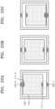
- FIGS. 21A-21C are views illustrating various alignment relationships between a frame unit and a panel unit of a display device according to an example not forming part of the present invention. Only some reference numerals are shown in FIGS. 21A-21C for convenience.
- FIG. 21B illustrates a case where the panel unit 110 is located at the center of the frame unit 120
- FIG. 21A illustrates a case where the panel unit 110 is located at a position shifted upward from the center of the frame unit 120
- FIG. 21C illustrates a case where the panel unit 110 is located at a position shifted downward from the center of the frame unit 120. That is, FIG. 21A through 21C illustrate various situations in which an alignment relationship between the panel unit 110 and the frame unit 120 may vary.
- the alignment relationship between the panel unit 110 and the frame unit 120 may vary when the panel unit 110 and the frame unit 10 are not installed at correct positions, when a process of installing or assembling the panel unit 110 and the frame unit 120 is being performed, when positions of the panel unit 110 and the frame unit 120 are distorted after installation or assembly, or when positions of the panel unit 110 and the frame unit 120 are intentionally adjusted to enhance aesthetics.
- a power transmission efficiency decreases as a distance between a power transmitter and a power receiver increases during a wireless power transmission.
- a distance between the wireless power transmitter 122 and the wireless power receiver 111 is greater than that in FIG. 21B , a power transmission amount of FIG. 21A may be less than that of FIG. 21B .
- FIG. 21C because a distance between the wireless power transmitter 122 and the wireless power receiver 111 is less than that in FIG. 21B , more power may be transmitted.
- power transmitter/receiver pairs may face each other.
- FIGS. 22A-22C are views illustrating a un-alignment compensation method of a display device according to an embodiment. Only some reference numerals are shown in FIGS. 22A-22C for convenience.
- the panel unit 110 is located at a position shifted upward, a distance between the first power transmitter 122-1 and the first power receiver 111-1 increases and thus a power transmission amount between the first power transmitter 122-1 and the first power receiver 111-1 may decrease. In contrast, a distance between the second power transmitter 122-2 and the second power receiver 111-2 decreases and thus a power transmission amount between the second power transmitter 122-2 and the second power receiver 111-2 may increase. Accordingly, the total amount of power received by the panel unit 110 may not change significantly.
- the same principle or method may apply to FIG. 21C .
- the second transmitter/receiver pair may compensate for the power loss due an increased distance between the first transmitter and the first receiver because a distance between the second transmitter and the second receiver will decrease by the same amount of the increased distance between the first transmitter and the first receiver. Accordingly, the second transmitter/receiver may recapture or restore the power loss by the first transmitter/receiver pair.
- FIG. 23 is a view illustrating a method of connecting wireless power receivers according to an embodiment.
- the first power receiver 111-1 and the second power receiver 111-2 are electrically connected in series to each other.
- output terminals of the first power receiver 111-1 and the second power receiver 111-2 are connected in series to each other so that an output voltage of the first power receiver 111-1 and an output voltage of the second power receiver 111-2 are added with the same polarity.
- a magnitude of a transmitted voltage increases as a coupling degree between a transmitter and a receiver increases.
- a sum of voltages of the two receivers does not substantially change, and thus a stable output voltage may be obtained.
- an output voltage of the first power receiver 111-1 decreases
- an output voltage of the second power receiver 111-2 increases. That is, the panel unit 110 may receive stable power even when no or little additional control is performed for compensation of un-alignment.
- the first power transmitter 122-1 and the second power transmitter 122-2 may also be connected in series to each other.
- the wireless power transmitter 122 may include a bar-shaped transmitting resonator that may be inserted into a thin frame.
- the wireless power receiver 111 may also include a bar-shaped receiving resonator corresponding to the transmitting resonator of the wireless power transmitter 122.
- Each of the transmitting resonator and the receiving resonator may be implemented as a solenoid.
- FIG. 24 is a view illustrating a bar-shaped transmitting resonator 1221 and a bar-shaped receiving resonator 1111 respectively used in the wireless power transmitter 122 and the wireless power receiver 111 according to an embodiment.
- each of the bar-shaped transmitting resonator 1221 and the bar-shaped receiving resonator 1111 may have a slightly curved shape rather than a straight line shape.
- two or more pairs of bar-shaped transmitting resonators 1221 and bar-shaped receiving resonators 1111 may be provided.
- the bar-shaped transmitting resonator 1221 and the bar-shaped receiving resonator 1111 may transmit/receive power.
- the bar-shaped transmitting resonator 1221 and the bar-shaped receiving resonator 1111 may transmit/receive power.
- two resonators are located side by side, it means that the two resonators extend in the same direction and are located to overlap each other in an extension direction, that is, a longitudinal direction, of the two resonators. In other words, when the two resonators are straight, the two resonators are located side by side like one pair of chopsticks.
- the bar-shaped receiving resonator 1111 may be located on an edge of a side of the panel unit 110 extending in a rim direction of the panel unit 110. That is, the wireless power receiver 111 may include the bar-shaped receiving resonator 1111 located on the edge of the side of the panel unit 110 and extending in the rim direction of the panel unit 110. Similarly, the wireless power transmitter 122 may include the bar-shaped transmitting resonator 1221 that may wirelessly transmit power to the bar-shaped receiving resonator 1111, and the bar-shaped transmitting resonator 1221 is located side by side with the bar-shaped receiving resonator 1111. The bar-shaped transmitting resonator 1221 may extend in a frame direction of the frame unit 120. The frame unit 120 and the panel unit 110 may be spaced apart from each other and may be fixed to the transparent support 130 so that the bar-shaped transmitting resonator 1221 is located side by side with the bar-shaped receiving resonator 1111.
- FIGS. 25A-25C are views of a un-alignment compensation method of a display device according to an example not forming part of the present invention. Only some reference numerals are shown in FIGS. 25A-25C for convenience.
- the panel unit 110 may stably receive power even when the panel unit 110 is located at a position shifted leftward or rightward from the center of the frame unit 120 as in FIG. 25B or FIG. 25C . Also, the same effect may be achieved even when a length of the bar-shaped receiving resonator 1111 is greater than a length of the bar-shaped transmitting resonator 1221.
- a length of transmitting/receiving resonators may be compensated for.
- the shorter resonator of the two resonators has to have a length enough to transmit sufficient power.
- a length difference between the two resonators increases, a un-alignment range that may be compensated may increase.
- a length of the longer resonator of the two resonators may be 10%, 30%, or 50% greater than a length of a shorter resonator.
- FIG. 26 is a view illustrating a method of reducing EMI of a display device according to an embodiment.
- a magnetic flux generated by the wireless power transmitter 122 of the frame unit 120 may be radiated into a free space to cause EMI.
- EMI may be reduced by allowing a magnetic flux generated by the first power transmitter 122-1 and a magnetic flux generated by the second power transmitter 122-2 to be generated in opposite directions as shown in FIG. 26 .
- each power transmitter includes a bar-shaped transmitting resonator
- magnetic fluxes may be generated in opposite directions by adjusting a winding direction of the bar-shaped transmitting resonator.
- the first power transmitter 122-1 and the second power transmitter 122-2 may face each other as shown in FIG. 26 , or the first power transmitter 122-1 and the second power transmitter 122-2 may be located at respective sides of the panel unit 110. The latter case may have low power transmission efficiency, but may be used when there are no frames facing each other as shown in FIG. 6 .
- the first power receiver 111-1 and the second power receiver 111-2 of the panel unit 110 may be connected in series to each other so that output voltages formed according to magnetic fluxes generated in opposite directions are added with the same polarity.
- the first power receiver 111-1 and the second power receiver 111-2 may face each other, or may be located at respective sides of the panel unit 110.
- FIG. 27 is a view illustrating a case where a panel unit and a frame unit separately operate according to an example not forming part of the present invention.
- the panel unit 110 may receive power by wire through the wired power receiver 115 as described above, the panel unit 110 may separately operate without the frame unit 120. That is, the display 112 may receive power from the wired power receiver 115 and may display an image.
- the frame unit 120 may separately operate without the panel unit 110. That is, the frame unit 120 may include an auxiliary functional unit that may operate independently from the panel unit 110, and may perform a useful function. When the frame unit 120 operates independently from the panel unit 110, it means that the frame unit 120 may operate without the panel unit 110.
- the frame unit 120 may include a speaker, a sensor, or a lighting device, and may operate as a speaker or an interior lighting device when the panel unit 110 is not operating or displaying an image.
- the auxiliary functional unit also receives power received by the power receiver 121. In this case, the frame unit 120 may determine that the panel unit 110 is not operating and may prevent unnecessary power consumption by turning off a circuit for wireless power transmission. That is, the wireless power transmitter 122 may determine whether the panel unit 110 exists at a distance in which wireless power transmission is possible, and may turn on or off wireless power transmission according to the determination.
- the frame unit 120 may selectively use one of the wireless power receiver 111 and the wired power receiver 115.
- the display 112 may receive power from the wired power receiver 115 at a higher priority than from the wireless power receiver 111.
- the panel power unit 113 may receive power from the wired power receiver 115 without receiving power from the wireless power receiver 111.
- the panel power unit 113 may receive power from at least one, which has a higher output voltage, from among the wireless power receiver 111 and the wired power receiver 115. In general, because an output voltage of the wireless power receiver 111 is equal to or less than an output voltage of the wired power receiver 115, the panel power unit 113 selectively receives power from the wired power receiver 115.
- the panel unit 110 may receive power by wire from the external power unit 410 without the frame unit 120, and may receive an image signal through wireless communication from an imaging device 430.
- the wireless communication may be long-range wireless communication.
- the panel unit 110 may receive power by wire without the frame unit 120, and may also receive an image signal by wire.
- the panel unit 110 may receive power and an image signal from a one connection (OC) box 440 through an OC cable.
- the panel unit 110 may receive power through wireless power transmission from the frame unit 120, and may also receive an image signal through wireless communication.
- the wireless communication may be long-range wireless communication.
- the frame unit 120 may receive power by wire from the external power unit 410 or the OC box 440, and the panel unit 110 may receive an image signal through wireless communication from the OC box 440 that supplies power to the frame unit 120 or the imaging device 430.
- the panel unit 110 may receive power through wireless power transmission from the frame unit 120, and may also receive an image signal through wireless communication from the frame unit 120.
- the panel unit 110 may transmit an image signal through short-range wireless communication.
- the frame unit 120 may include an image receiver and a short-range wireless transmitter that transmits through short-range wireless communication an image signal received by the image receiver, and the panel unit 110 may include a short-range wireless receiver that may receive an image signal through short-range wireless communication from the short-range wireless transmitter when the panel unit 110 is spaced apart from the frame unit 120.
- the display 112 may display an image based on an image signal received by the short-range wireless receiver.
- the short-range wireless transmitter of the frame unit 120 may transmit an image signal received from the image receiver, or may process an image signal received from the image receiver to be suitable for short-range wireless communication and may transmit the processed image signal.
- the frame unit 120 may receive power and an image signal from the OC box 440 through the OC cable.
- a user may change a size, a color, a pattern, a shape, and an additional function of a frame by replacing only the frame unit 120 while leaving the panel unit 110 as is. Also, the user may replace the panel unit 110 with one having better performance or a different design while leaving the frame unit 120 as is.
- FIG. 32 is a flowchart illustrating an operating method of a display device according to an embodiment.
- the frame unit 120 may receive power from the outside (e.g., an outlet).
- the frame unit 120 may wirelessly transmit the received power.
- the panel unit 110 may wirelessly receive power from the frame unit 120 when being spaced apart from the frame unit 120.
- the panel unit 110 may display an image.
- Embodiments of the disclosure may be provided as a computer-executable program product, and the program may be stored in a non-transitory computer-readable recording medium.
- Examples of the computer-readable recording medium include all recording media such as a magnetic medium, an optical medium, read-only memory (ROM), and random-access memory (RAM).
Landscapes
- Engineering & Computer Science (AREA)
- Computer Networks & Wireless Communication (AREA)
- Power Engineering (AREA)
- Signal Processing (AREA)
- Theoretical Computer Science (AREA)
- Multimedia (AREA)
- General Physics & Mathematics (AREA)
- Physics & Mathematics (AREA)
- General Engineering & Computer Science (AREA)
- Human Computer Interaction (AREA)
- Business, Economics & Management (AREA)
- Accounting & Taxation (AREA)
- Marketing (AREA)
- Computer Hardware Design (AREA)
- Devices For Indicating Variable Information By Combining Individual Elements (AREA)
- Mechanical Engineering (AREA)
Description
- This application is based on and claims priority to
Korean Patent Application No. 10-2019-0163974, filed on December 10, 2019 - The disclosure relates to a display device that appears to be floating in the air and an operating method thereof.
- Today, when selecting electronic products, consumers do not only consider the functionality and practicality of the products, but also tend to select or purchase products that may blend in with their lives and aesthetically fill the users' spaces. With the rise of Artygen (Arty Generation), which is a consumer group that values designs combined with product functions, companies are adopting a Techart Marketing strategy that involves combining technology with art and are releasing products in which artistic designs are combined with culture. For example, a TV that appears like a picture frame, displayed in an art museum, has been released and spotlighted.
KR 2015 0090668 A US 2014/361633A1 discloses a contactless power supply system,WO 2019/203445 A1 discloses a display system including a display receiving a second power supply signal, andUS 2017/192486A1 discloses a display apparatus including a wireless power receiver. - Provided are a display device that appears to be floating in space and an operating method thereof.
- Additional aspects will be set forth in part in the description which follows and, in part, will be apparent from the description, or may be learned by practice of the presented embodiments.
- According to the invention, there is provided a display device according to claim 1. Preferred features are set out in the dependent claims.
- The above and other aspects, features, and advantages of certain embodiments of the disclosure will become more apparent from the following description taken in conjunction with the accompanying drawings, in which:
-
FIG. 1 is a view of a display device according to an embodiment; -
FIG. 2 is an exploded view of a display device according to an embodiment; -
FIGS. 3 through 7 are views illustrating display devices having various shapes according to embodiments; -
FIG. 8 is a view illustrating a method of fixing a panel unit and a frame unit to a transparent support according to an embodiment; -
FIG. 9 is a view illustrating a method of connecting a stand to a display device, according to an embodiment; -
FIG. 10 is a view illustrating a method of connecting a stand to a display device according to an embodiment; -
FIG. 11 is a view illustrating a method of connecting a stand to a display device according to an embodiment; -
FIG. 12 illustrates photographs of a display device according to an embodiment; -
FIG. 13 is a view illustrating a method of installing a display device on a wall according to an embodiment; -
FIG. 14 is a view of an extension screw according to an embodiment; -
FIG. 15 is a view illustrating a method of installing a display device on a wall according to an embodiment; -
FIG. 16 is a diagram illustrating a display device according to an embodiment; -
FIG. 17 is a detailed diagram illustrating a display device according to an embodiment; -
FIG. 18 is a view illustrating a display device and a method of connecting external power according to an embodiment; -
FIG. 19 is a diagram illustrating an external power unit according to an embodiment; -
FIGS. 20A-20D are views illustrating various arrangements of a wireless power transmitter and a wireless power receiver according to an embodiment; -
FIGS. 21A-21C are views illustrating various alignment relationships between a frame unit and a panel unit of a display device according to an example not forming part of the present invention; -
FIGS. 22A-22C are views illustrating an un-alignment compensation method of a display device according to an embodiment; -
FIG. 23 is a circuit diagram illustrating a method of connecting wireless power receivers according to an embodiment; -
FIG. 24 is a view illustrating a bar-shaped transmitting resonator and a bar-shaped receiving resonator according to an embodiment; -
FIGS. 25A-25C are views of an un-alignment compensation method of a display device according to an example not forming part of the present invention; -
FIG. 26 is a view of a method of reducing electromagnetic interference (EMI) of a display device according to an embodiment; -
FIG. 27 is a view illustrating a case where a panel unit and a frame unit separately operate according to an example not forming part of the present invention; -
FIG. 28 is a view illustrating a wired power preference circuit of a panel unit according to an embodiment; -
FIG. 29 is a view illustrating a diode O-ring circuit of a panel unit, according to an embodiment; -
FIG. 30 is a view illustrating a method in which a panel unit receives an image signal according to an example not forming part of the present invention; -
FIG. 31 is a view illustrating a method in which a panel unit receives an image signal according to an embodiment; and -
FIG. 32 is a flowchart illustrating an operating method of a display device according to an embodiment. - The disclosure will now be described more detail with reference to the accompanying drawings, in which embodiments of the disclosure are shown. In the description, certain detailed explanations of related or well-known functions or elements are omitted when it is deemed that they may unnecessarily obscure the essence of the disclosure. In the drawings, elements having substantially the same functions are denoted by the same reference numerals or symbols. An apparatus and a method thereof will be described together when necessary for convenience of explanation. Throughout the disclosure, when a component is referred to as being "connected" to another component, it will be understood that the component is "directly connected" to the other component or is "electrically connected" to the other component with another component therebetween.
- Throughout the disclosure, the expression "at least one of a, b or c" may include only a, only b, only c, both a and b, both a and c, both b and c, all of a, b, and c, or any combinations thereof.
-
FIG. 1 is a view of a display device according to an embodiment. Referring toFIG. 1 , adisplay device 100 according to an embodiment of the disclosure includes apanel unit 110 and aframe unit 120. Thepanel unit 110 is a portion on which an image is displayed, and theframe unit 120 is a portion located around thepanel unit 110 and configured to make thepanel unit 110 look as if thepanel unit 110 is inside a picture frame. Because thepanel unit 110 and theframe unit 120 are spaced apart from each other without contacting each other as shown inFIG. 1 , thepanel unit 110 looks as if it is floating in the air. - Along the z-axis perpendicular to a surface of the
panel unit 110 on which an image is displayed, a side where thepanel unit 110 displays the image is referred to as a front side and the opposite side is referred to as a rear side. A direction of an xy plane parallel to the surface of thepanel unit 110 on which the image is displayed is referred to as a lateral direction. On the xy plane, a direction toward the center of thepanel unit 110 is referred to as an inner direction and the opposite direction is referred to as an outer direction. - The
frame unit 120 may be located outside thepanel unit 110 and may surround thepanel unit 110. Theframe unit 120 may have a closed curve shape as shown inFIG. 1 , and may completely surround thepanel unit 110. In this case, theframe unit 120 is described as enclosing thepanel unit 110. Theframe unit 120 and thepanel unit 110 may be located on the same plane. Theframe unit 120 may be located slightly in front of or behind thepanel unit 110. Thepanel unit 110 may have a flat shape, and theframe unit 120 may have a closed or open bar shape. Each of thepanel unit 110 and theframe unit 120 may have a quadrangular shape. However, one or more embodiments are not limited thereto, and thepanel unit 110 and theframe unit 120 may be in the form of any other shapes. Thepanel unit 110 and theframe unit 120 may be arranged to appear to be spaced apart from each other when viewed from the front. -
FIG. 2 is an exploded view of a display device according to an embodiment. Referring toFIG. 2 , thedisplay device 100 according to an embodiment of the disclosure may include thepanel unit 110, theframe unit 120 and atransparent support 130. Thetransparent support 130 fixes thepanel unit 110 and theframe unit 120 at separated positions, and makes the panel unit no look as if thepanel unit 110 is floating in the air without being connected to theframe unit 120. That is, thepanel unit 110 and theframe unit 120 may be spaced apart from each other and may be fixed to thetransparent support 130. Thetransparent support 130 may include a frame fixing portion and a panel fixing portion. When theframe unit 120 is fixed to the frame fixing portion and thepanel unit 110 is fixed to the panel fixing portion, theframe unit 120 and thepanel unit 110 may be spaced apart from each other without contacting each other. A method of fixing thepanel unit 110 and theframe unit 120 to thetransparent support 130 will be described below with reference toFIG. 8 . Thedisplay device 100 may not include thetransparent support 130, and in this case, a method of fixing thepanel unit 110 and theframe unit 120 at separated positions will be described below with reference toFIG. 15 . -
FIGS. 3 through 7 are views illustrating display devices having various shapes according to embodiments. - Referring to
FIG. 3 , theframe unit 120 may have a circular shape, instead of a quadrangular shape. However, theframe unit 120 may have any other shapes. Referring toFIG. 4 , thepanel unit 110 may have a circular shape, instead of a quadrangular shape. Thepanel unit 110 may have any other shapes. Both thepanel unit 110 and theframe unit 120 may not have quadrangular shapes. For example, both thepanel unit 110 and theframe unit 120 may have circular shapes. Referring toFIGS. 5 and6 , theframe unit 120 may not have a closed curve shape, and may surround only a part of thepanel unit 110. Here, theframe unit 120 may surround only three sides of thepanel unit 110.FIG. 6 refers to an example not forming part of the present invention. Referring toFIG. 7 , theframe unit 120 may include a plurality of portions 120-1 and 120-2 that are separated from one another. Here, thepanel unit 110 may be disposed between a first portion 120-1 and a second portion 120-2 among the plurality ofportions 120. -
FIG. 8 is a view illustrating a method of fixing a panel unit and a frame unit to a transparent support according to an embodiment. Thepanel unit 110 and theframe unit 120 may be fixed to a front surface of thetransparent support 130. That is, thetransparent support 130 may be fixed to rear surfaces of thepanel unit 110 and theframe unit 120. - As described above, the
frame unit 120 may enclose thepanel unit 110. In this case, when viewed from the front, theframe unit 120 may be fixed to thetransparent support 130 to enclose thepanel unit 110. - The
panel unit 110 may have a Video Electronics Standards Association (VESA) standard mounting interface to be compatible with various display mounts. Accordingly, thetransparent support 130 may also have a VESA standard mounting interface, and thepanel unit 110 and thetransparent support 130 may be fixed by using one ormore screws 210 according to the VESA standard. Thepanel unit 110 and thetransparent support 130 may be fixed by using other fixing methods. Thepanel unit 110 and thetransparent support 130 may be detachably manufactured, or may be integrally manufactured. - The
frame unit 120 and thetransparent support 130 may also be fixed by using various fixing methods. Theframe unit 120 and thetransparent support 130 may also be detachably manufactured, or may be integrally manufactured. - The
transparent support 130 may be entirely transparent or partially transparent. That is, thetransparent support 130 may include a transparent portion and an opaque portion. A portion of thetransparent support 130 that connects thepanel unit 110 and theframe unit 120 may not be opaque. When thetransparent support 130 is fixed to the rear surfaces of thepanel unit 110 and theframe unit 120, a portion of thetransparent support 130 that is visible when viewed from the front may be transparent. - The
transparent support 130 or the transparent portion of thetransparent support 130 may be formed of a transparent material. The transparent material may have a strength high enough to withstand a weight of thepanel unit 110 and/or theframe unit 120, and may include, for example, glass or acryl. Theframe unit 120 and thetransparent support 130 may be integrally manufactured by using a transparent material, or only theframe unit 120 may be coated. - When an element is transparent, it means that incident visible light is entirely or partially transmitted through the element. A visible light transmittance of the transparent portion of the
transparent support 130 may be, for example, 10 %, 60 %, or 90 %. The effect that thepanel unit 110 looks as if it is floating in the air increases as a visible light transmittance of thetransparent support 130 increases. However, when a visible light transmittance is low, but an object behind thetransparent support 130 is visible through thetransparent support 130, thepanel unit 110 may look as if it is floating in the air. Thetransparent support 130 may be colorless in order to improve levitation effect, or may have a specific color in order to enhance aesthetics. - The
panel unit 110, theframe unit 120, and thetransparent support 130 may be fixed in different forms. For example, thepanel unit 110 may be fixed to the front surface of thetransparent support 130, and theframe unit 120 may be fixed to an outer surface of thetransparent support 130. Alternatively, thetransparent support 130 may have a donut shape in which the center is empty, and thepanel unit 110 and theframe unit 120 may be respectively fixed to an inner side and the outer side of thetransparent support 130. Regardless of how thepanel unit 110, theframe unit 120, and thetransparent support 130 are fixed, a portion of thetransparent support 130 that is visible when viewed from the front may be configured to be transparent. - When the
frame unit 120 and thepanel unit 110 are fixed to thetransparent support 130 so that theframe unit 120 encloses thepanel unit 110 when viewed from the front, an entire space between theframe unit 120 and thepanel unit 110 when viewed from the front may be transparent. That is, thetransparent support 130 may include the transparent portion that occupies the entire space between theframe unit 120 and thepanel unit 110 when viewed from the front. -
FIGS. 9 through 11 are views illustrating various methods of connecting a stand to a display device according to embodiments. Referring toFIGS. 9 and10 , in order to increase the effect that thepanel unit 110 looks as if it is floating in the air, astand 310 may be connected to the bottom of theframe unit 120. Referring toFIG. 11 , when thestand 310 is connected to thepanel unit 110, aneck portion 311 of thestand 310 may be formed of a transparent material to enhance aesthetics. In this case, not only thepanel unit 110, but also theframe unit 120 may look as if they are floating in the air.FIG. 12 illustrates photographs of a display device actually manufactured by the applicant according to an embodiment. -
FIG. 13 is a view illustrating a method of installing a display device on a wall according to an embodiment. Referring toFIG. 13 , as described with reference toFIG. 8 , thepanel unit 110 may have a VESA standard mounting interface, and may be fixed to a wall-mount 230 by using one or more extension screws 220 according to the VESA standard. -
FIG. 14 is a view of an extension screw according to an embodiment. Referring toFIG. 14 , theextension screw 220 may have a two-step header structure. Afront header 221 may be used to couple thepanel unit 110 and thetransparent support 130, and arear header 222 may be fixed to the wall-mount 230 so as to fix thetransparent support 130 to thewall mount 230. - That is, the
panel unit 110 may have screw holes according to a VESA mounting interface standard, thetransparent support 130 may have screw holes according to the VESA mounting interface standard, and theextension screw 220 may include thefront header 221 that couples thepanel unit 110 and thetransparent support 130 and therear header 222 that may be fixed to the wall-mount 230 according to the VESA mounting interface standard. Thepanel unit 110 and/or theframe unit 120 may be installed to be closely attached to the wall, or may be installed to be spaced apart by a certain distance from the wall for a desired effect. -
FIG. 15 is a view illustrating a method of installing a display device on a wall according to an embodiment. Referring toFIG. 15 , theframe unit 120 may also be fixed to a wall-mount 240, and in this case, thetransparent support 130 for fixing thepanel unit 110 and theframe unit 120 may not be required. That is, thepanel unit 110 may have screw holes according to the VESA mounting interface standard to fix thepanel unit 110 to the wall-mount 230, and theframe unit 120 may include a coupling member for fixing theframe unit 120 to the wall-mount 240. The coupling member for fixing theframe unit 120 to the wall-mount 240 may have a screw hole. -
FIG. 16 is a diagram illustrating a display device according to an embodiment. Referring toFIG. 16 , theframe unit 120 may include apower receiver 121 and awireless power transmitter 122, and thepanel unit 110 may includewireless power receiver 111 and adisplay 112. Thepower receiver 121 may receive power by wire or wirelessly from the outside. Thewireless power transmitter 122 may wirelessly transmit power received by thepower receiver 121. In this case, thewireless power transmitter 122 may wirelessly transmit part or the whole of the power received by thepower receiver 121. Thewireless power receiver 111 may wirelessly receive power from thewireless power transmitter 122 when thepanel unit 110 and theframe unit 120 are spaced apart from each other. Thedisplay 112 may receive power from thewireless power receiver 111 and may display an image. As power is wirelessly transmitted from theframe unit 120 to thepanel unit 110, an electric wire does not need to be provided between theframe unit 120 and thepanel unit 110, thereby providing the effect that thepanel unit 110 looks as if it is floating in the air to a user and enhancing aesthetic effect. -
FIG. 17 is a detailed diagram illustrating a display device according to another embodiment. Referring toFIG. 17 , theframe unit 120 may further include aframe power unit 123. Theframe power unit 123 may receive power from thepower receiver 121, and may supply power to thewireless power transmitter 122. Thepanel unit 110 may further include apanel power unit 113 and animage board 114. Thepanel power unit 113 may receive power from thewireless power receiver 111, and may supply power to theimage board 114. Theimage board 114 may supply power to thedisplay 112 and may apply an image signal. Thepanel unit 110 may further include awired power receiver 115. Thepanel power unit 113 may receive power from the wiredpower receiver 115. That is, thepanel power unit 113 may receive power from thewireless power receiver 111 and/or the wiredpower receiver 115, and thus thepanel unit 110 may operate by wirelessly receiving power from theframe unit 120, and/or may operate by separately receiving power by wire directly from an outlet without passing through theframe unit 120. -
FIG. 18 is a view illustrating a display device and a method of connecting external power according to an embodiment. Referring toFIG. 18 , thewireless power transmitter 122 may include a plurality of power transmitters, and thewireless power receiver 111 may include a plurality of power receivers. For example, thewireless power transmitter 122 may include a first power transmitter 122-1 and a second power transmitter 122-2, and thepanel unit 110 may include a first power receiver 111-1 and a second power receiver 111-2. The first power receiver 111-1 may receive power from the first power transmitter 122-1, and the second power receiver 111-2 may receive power from the second power transmitter 122-2. - The first power receiver 111-1 may be located on an edge of a side of the
panel unit 110, and the second power receiver 111-2 may be located on an edge of the opposite side of thepanel unit 110. That is, the first power receiver 111-1 and the second power receiver 111-2 may be located opposite to each other about the center of thepanel unit 110. In this case, the first power receiver 111-1 and the second power receiver 111-2 are described as facing each other. - The first power transmitter 122-1 may be located outside the first power receiver 111-1, and the second power transmitter 122-2 may be located outside the second power receiver 111-2. That is, the first power transmitter 122-1 and the second power transmitter 122-2 may be located opposite to each other about the center of the
panel unit 110 to face each other. Thetransparent support 130 may fix theframe unit 120 and thepanel unit 110 so that theframe unit 120 and thepanel unit 110 are spaced apart from each other, and the first power transmitter 122-1 is located outside the first power receiver 111-1 and the second power transmitter 122-2 is located outside the second power receiver 111-2. While the above examples describe only two power transmitters and receivers at respective locations, one or more embodiments are not limited thereto, and the number of power transmitter and power receiver and their respective locations may vary depending on the design of the frame unit and the panel unit. - The
power receiver 121 of theframe unit 120 may receive power by wire from anexternal power unit 410. In this case, in order to enhance aesthetic effect, a transparent power line having a certain transmittance or more may be used as acable 420 for connecting thereceiver 121 and theexternal power unit 410. -
FIG. 19 is a diagram illustrating an external power unit according to an embodiment. Referring toFIG. 19 , theexternal power unit 410 may include an electromagnetic interference (EMI) filter, a bridge diode, a power factor correction (PFC) circuit, and a direct current (DC)/DC converter. When necessary, some elements may be omitted. For example, when power is less than 75 W, the PFC circuit may be omitted. - The
power receiver 121 may directly receive power from an alternating current (AC) power source without passing through theexternal power unit 410. In this case, as an EMI filter, a bridge diode, and a PFC circuit are included in theframe power unit 123 and a volume of theframe power unit 123 may increase. In such a case, a design of theframe unit 120 may be affected. - The wired
power receiver 115 of thepanel unit 110 may also receive power by wire from theexternal power unit 410. Thepower receiver 121 of theframe unit 120 and the wiredpower receiver 115 of thepanel unit 110 may include the same power receiving interface, so that the sameexternal power unit 410 is used for both theframe unit 120 and thepanel unit 110. -
FIGS. 20A-20D are views illustrating various arrangements of a wireless power transmitter and a wireless power receiver according to one or more embodiments. Only some reference numerals are shown inFIGS. 20A-20D for convenience. - Referring to
FIGS. 20A and 20B , power transmitter/receiver pairs 111-1 and 122-1, and 111-2 and 122-2 may face each other. - Referring to
FIG. 20C , which represents an example not forming part of the present invention, the power transmitter/receiver pairs 111-1 and 122-1, and 111-2 and 122-2 may be located on a side of thepanel unit 110. That is, thewireless power receiver 111 may include the first power receiver 111-1 located on a side of thepanel unit 110, and the second power receiver 111-2 located on the same side of thepanel unit 110. Thewireless power transmitter 122 may include the first power transmitter 122-1 located on a side of theframe unit 120, and the second power transmitter 122-2 located on the same side of theframe unit 120. The first power receiver 111-1 and the second power receiver 111-2 may be aligned with each other. When the first power receiver 111-1 and the second power receiver 111-2 are aligned with each other, it means that the first power receiver 111-1 and the second power receiver 111-2 are aligned with each other along a rim of thepanel unit 110. The rim may be a side of a polygon when thepanel unit 110 has a polygonal shape, and may be an arc when thepanel unit 110 has a circular shape. The first power transmitter 122-1 and the second power transmitter 122-2 may be aligned with each other. When the first power transmitter 122-1 and the second power transmitter 122-2 are aligned with each other, it means that the first power transmitter 122-1 and the second power transmitter 122-2 are aligned with each other along a frame of theframe unit 120. The alignment may include not only complete alignment, but also substantial alignment. An arrangement inFIG. 20C is especially useful when there are no frames facing each other as shown inFIG. 6 . - Referring to
FIG. 20D , power transmitter/receiver pairs may face each other in various directions, for example, vertically and horizontally, about the center of thepanel unit 110. Here, the power transmitter/receiver pairs may be disposed on each of four sides of thepanel unit 110 and theframe unit 120. -
FIGS. 21A-21C are views illustrating various alignment relationships between a frame unit and a panel unit of a display device according to an example not forming part of the present invention. Only some reference numerals are shown inFIGS. 21A-21C for convenience. -
FIG. 21B illustrates a case where thepanel unit 110 is located at the center of theframe unit 120,FIG. 21A illustrates a case where thepanel unit 110 is located at a position shifted upward from the center of theframe unit 120, andFIG. 21C illustrates a case where thepanel unit 110 is located at a position shifted downward from the center of theframe unit 120. That is,FIG. 21A through 21C illustrate various situations in which an alignment relationship between thepanel unit 110 and theframe unit 120 may vary. For example, the alignment relationship between thepanel unit 110 and theframe unit 120 may vary when thepanel unit 110 and the frame unit 10 are not installed at correct positions, when a process of installing or assembling thepanel unit 110 and theframe unit 120 is being performed, when positions of thepanel unit 110 and theframe unit 120 are distorted after installation or assembly, or when positions of thepanel unit 110 and theframe unit 120 are intentionally adjusted to enhance aesthetics. - Furthermore, a power transmission efficiency decreases as a distance between a power transmitter and a power receiver increases during a wireless power transmission. Referring to
FIG. 21A , because a distance between thewireless power transmitter 122 and thewireless power receiver 111 is greater than that inFIG. 21B , a power transmission amount ofFIG. 21A may be less than that ofFIG. 21B . Referring toFIG. 21C , because a distance between thewireless power transmitter 122 and thewireless power receiver 111 is less than that inFIG. 21B , more power may be transmitted. In order to make up for a phenomenon where a power transmission amount varies according to an alignment relationship between thepanel unit 110 and theframe unit 120, power transmitter/receiver pairs may face each other. -
FIGS. 22A-22C are views illustrating a un-alignment compensation method of a display device according to an embodiment. Only some reference numerals are shown inFIGS. 22A-22C for convenience. - Referring to
FIG. 22A , because thepanel unit 110 is located at a position shifted upward, a distance between the first power transmitter 122-1 and the first power receiver 111-1 increases and thus a power transmission amount between the first power transmitter 122-1 and the first power receiver 111-1 may decrease. In contrast, a distance between the second power transmitter 122-2 and the second power receiver 111-2 decreases and thus a power transmission amount between the second power transmitter 122-2 and the second power receiver 111-2 may increase. Accordingly, the total amount of power received by thepanel unit 110 may not change significantly. The same principle or method may apply toFIG. 21C . That is, when power transmitter/receiver pairs face each other and a distance between one power transmitter/receiver pair decreases as a distance between another power transmitter/receiver pair increases, a decrease in power transmission efficiency due to un-alignment between a frame unit and a panel unit may be compensated. In other words, by providing a second transmitter/receiver pair at a location opposite from a first transmitter/receiver pair, the second transmitter/receiver pair may compensate for the power loss due an increased distance between the first transmitter and the first receiver because a distance between the second transmitter and the second receiver will decrease by the same amount of the increased distance between the first transmitter and the first receiver. Accordingly, the second transmitter/receiver may recapture or restore the power loss by the first transmitter/receiver pair. -
FIG. 23 is a view illustrating a method of connecting wireless power receivers according to an embodiment. Referring toFIG. 23 , the first power receiver 111-1 and the second power receiver 111-2 are electrically connected in series to each other. Specifically, output terminals of the first power receiver 111-1 and the second power receiver 111-2 are connected in series to each other so that an output voltage of the first power receiver 111-1 and an output voltage of the second power receiver 111-2 are added with the same polarity. A magnitude of a transmitted voltage increases as a coupling degree between a transmitter and a receiver increases. Accordingly, when two power receivers are connected in this way, even if an output voltage of one of the two receivers increases and an output voltage of the other decreases due to un-alignment between a frame unit and a panel unit as described above with reference toFIGS. 22A-22C , a sum of voltages of the two receivers does not substantially change, and thus a stable output voltage may be obtained. For example, when an output voltage of the first power receiver 111-1 decreases, an output voltage of the second power receiver 111-2 increases. That is, thepanel unit 110 may receive stable power even when no or little additional control is performed for compensation of un-alignment. The first power transmitter 122-1 and the second power transmitter 122-2 may also be connected in series to each other. - The
wireless power transmitter 122 may include a bar-shaped transmitting resonator that may be inserted into a thin frame. Thewireless power receiver 111 may also include a bar-shaped receiving resonator corresponding to the transmitting resonator of thewireless power transmitter 122. Each of the transmitting resonator and the receiving resonator may be implemented as a solenoid. -
FIG. 24 is a view illustrating a bar-shapedtransmitting resonator 1221 and a bar-shapedreceiving resonator 1111 respectively used in thewireless power transmitter 122 and thewireless power receiver 111 according to an embodiment. In another embodiment, each of the bar-shapedtransmitting resonator 1221 and the bar-shapedreceiving resonator 1111 may have a slightly curved shape rather than a straight line shape. In addition, two or more pairs of bar-shapedtransmitting resonators 1221 and bar-shapedreceiving resonators 1111 may be provided. - When the bar-shaped
transmitting resonator 1221 and the bar-shapedreceiving resonator 1111 are located side by side, the bar-shapedtransmitting resonator 1221 and the bar-shapedreceiving resonator 1111 may transmit/receive power. When two resonators are located side by side, it means that the two resonators extend in the same direction and are located to overlap each other in an extension direction, that is, a longitudinal direction, of the two resonators. In other words, when the two resonators are straight, the two resonators are located side by side like one pair of chopsticks. - The bar-shaped
receiving resonator 1111 may be located on an edge of a side of thepanel unit 110 extending in a rim direction of thepanel unit 110. That is, thewireless power receiver 111 may include the bar-shapedreceiving resonator 1111 located on the edge of the side of thepanel unit 110 and extending in the rim direction of thepanel unit 110. Similarly, thewireless power transmitter 122 may include the bar-shapedtransmitting resonator 1221 that may wirelessly transmit power to the bar-shapedreceiving resonator 1111, and the bar-shapedtransmitting resonator 1221 is located side by side with the bar-shapedreceiving resonator 1111. The bar-shapedtransmitting resonator 1221 may extend in a frame direction of theframe unit 120. Theframe unit 120 and thepanel unit 110 may be spaced apart from each other and may be fixed to thetransparent support 130 so that the bar-shapedtransmitting resonator 1221 is located side by side with the bar-shapedreceiving resonator 1111. -
FIGS. 25A-25C are views of a un-alignment compensation method of a display device according to an example not forming part of the present invention. Only some reference numerals are shown inFIGS. 25A-25C for convenience. - Referring to
FIGS. 25A-25C , when a length of the bar-shapedtransmitting resonator 1221 is greater than a length of the bar-shapedreceiving resonator 1111, thepanel unit 110 may stably receive power even when thepanel unit 110 is located at a position shifted leftward or rightward from the center of theframe unit 120 as inFIG. 25B or FIG. 25C . Also, the same effect may be achieved even when a length of the bar-shapedreceiving resonator 1111 is greater than a length of the bar-shapedtransmitting resonator 1221. That is, by making lengths of transmitting/receiving resonators asymmetric to each other, un-alignment in an extension direction of the transmitting/receiving resonators, that is, a longitudinal direction of the transmitting/receiving resonators may be compensated for. At this time, the shorter resonator of the two resonators has to have a length enough to transmit sufficient power. A length difference between the two resonators increases, a un-alignment range that may be compensated may increase. For example, a length of the longer resonator of the two resonators may be 10%, 30%, or 50% greater than a length of a shorter resonator. -
FIG. 26 is a view illustrating a method of reducing EMI of a display device according to an embodiment. A magnetic flux generated by thewireless power transmitter 122 of theframe unit 120 may be radiated into a free space to cause EMI. EMI may be reduced by allowing a magnetic flux generated by the first power transmitter 122-1 and a magnetic flux generated by the second power transmitter 122-2 to be generated in opposite directions as shown inFIG. 26 . When each power transmitter includes a bar-shaped transmitting resonator, magnetic fluxes may be generated in opposite directions by adjusting a winding direction of the bar-shaped transmitting resonator. In this case, the first power transmitter 122-1 and the second power transmitter 122-2 may face each other as shown inFIG. 26 , or the first power transmitter 122-1 and the second power transmitter 122-2 may be located at respective sides of thepanel unit 110. The latter case may have low power transmission efficiency, but may be used when there are no frames facing each other as shown inFIG. 6 . - The first power receiver 111-1 and the second power receiver 111-2 of the
panel unit 110 may be connected in series to each other so that output voltages formed according to magnetic fluxes generated in opposite directions are added with the same polarity. In this case, the first power receiver 111-1 and the second power receiver 111-2 may face each other, or may be located at respective sides of thepanel unit 110. -
FIG. 27 is a view illustrating a case where a panel unit and a frame unit separately operate according to an example not forming part of the present invention. - Because the
panel unit 110 may receive power by wire through the wiredpower receiver 115 as described above, thepanel unit 110 may separately operate without theframe unit 120. That is, thedisplay 112 may receive power from the wiredpower receiver 115 and may display an image. - Also, the
frame unit 120 may separately operate without thepanel unit 110. That is, theframe unit 120 may include an auxiliary functional unit that may operate independently from thepanel unit 110, and may perform a useful function. When theframe unit 120 operates independently from thepanel unit 110, it means that theframe unit 120 may operate without thepanel unit 110. For example, theframe unit 120 may include a speaker, a sensor, or a lighting device, and may operate as a speaker or an interior lighting device when thepanel unit 110 is not operating or displaying an image. The auxiliary functional unit also receives power received by thepower receiver 121. In this case, theframe unit 120 may determine that thepanel unit 110 is not operating and may prevent unnecessary power consumption by turning off a circuit for wireless power transmission. That is, thewireless power transmitter 122 may determine whether thepanel unit 110 exists at a distance in which wireless power transmission is possible, and may turn on or off wireless power transmission according to the determination. - When power is simultaneously supplied by wire to the
frame unit 120 and thepanel unit 110, voltage collision may occur between an output of thewireless power receiver 111 and an output of the wiredpower receiver 115 of thepanel unit 110. In order to prevent the voltage collision, theframe unit 120 may selectively use one of thewireless power receiver 111 and the wired power receiver 115.For example, thedisplay 112 may receive power from the wiredpower receiver 115 at a higher priority than from thewireless power receiver 111. - In an embodiment, by using a wired power preference circuit as shown in
FIG. 28 , when power is received by the wiredpower receiver 115, thepanel power unit 113 may receive power from the wiredpower receiver 115 without receiving power from thewireless power receiver 111. In another embodiment, by using a diode Oring circuit as shown inFIG. 29 , thepanel power unit 113 may receive power from at least one, which has a higher output voltage, from among thewireless power receiver 111 and the wiredpower receiver 115. In general, because an output voltage of thewireless power receiver 111 is equal to or less than an output voltage of the wiredpower receiver 115, thepanel power unit 113 selectively receives power from the wiredpower receiver 115. - Various methods using which the
panel unit 110 receives an image signal will be described with reference toFIGS. 30 and31 . - Referring to
FIG. 30 , which represents an example not forming part of the present invention, thepanel unit 110 may receive power by wire from theexternal power unit 410 without theframe unit 120, and may receive an image signal through wireless communication from animaging device 430. In this case, the wireless communication may be long-range wireless communication. - Also, the
panel unit 110 may receive power by wire without theframe unit 120, and may also receive an image signal by wire. In this case, thepanel unit 110 may receive power and an image signal from a one connection (OC)box 440 through an OC cable. - The
panel unit 110 may receive power through wireless power transmission from theframe unit 120, and may also receive an image signal through wireless communication. In this case, the wireless communication may be long-range wireless communication. Theframe unit 120 may receive power by wire from theexternal power unit 410 or theOC box 440, and thepanel unit 110 may receive an image signal through wireless communication from theOC box 440 that supplies power to theframe unit 120 or theimaging device 430. - Referring to
FIG. 31 , thepanel unit 110 may receive power through wireless power transmission from theframe unit 120, and may also receive an image signal through wireless communication from theframe unit 120. In this case, because thepanel unit 110 and theframe unit 120 are located close to each other, thepanel unit 110 may transmit an image signal through short-range wireless communication. That is, theframe unit 120 may include an image receiver and a short-range wireless transmitter that transmits through short-range wireless communication an image signal received by the image receiver, and thepanel unit 110 may include a short-range wireless receiver that may receive an image signal through short-range wireless communication from the short-range wireless transmitter when thepanel unit 110 is spaced apart from theframe unit 120. When a distance between thepanel unit 110 and theframe unit 120 is several centimeters or less, 4 K or higher image signal transmission may be performed. Thedisplay 112 may display an image based on an image signal received by the short-range wireless receiver. The short-range wireless transmitter of theframe unit 120 may transmit an image signal received from the image receiver, or may process an image signal received from the image receiver to be suitable for short-range wireless communication and may transmit the processed image signal. Theframe unit 120 may receive power and an image signal from theOC box 440 through the OC cable. - A user may change a size, a color, a pattern, a shape, and an additional function of a frame by replacing only the
frame unit 120 while leaving thepanel unit 110 as is. Also, the user may replace thepanel unit 110 with one having better performance or a different design while leaving theframe unit 120 as is. -
FIG. 32 is a flowchart illustrating an operating method of a display device according to an embodiment. Referring toFIG. 32 , in operation S110, theframe unit 120 may receive power from the outside (e.g., an outlet). In operation S120, theframe unit 120 may wirelessly transmit the received power. In operation S130, thepanel unit 110 may wirelessly receive power from theframe unit 120 when being spaced apart from theframe unit 120. In operation S140, thepanel unit 110 may display an image. - Embodiments of the disclosure may be provided as a computer-executable program product, and the program may be stored in a non-transitory computer-readable recording medium. Examples of the computer-readable recording medium include all recording media such as a magnetic medium, an optical medium, read-only memory (ROM), and random-access memory (RAM).
- While the invention has been particularly shown and described with reference to embodiments thereof, the embodiments are non-limiting examples of the invention, and should be considered in a descriptive sense only and not for purposes of limitation. The invention is defined by the appended claims.
Claims (13)
- A display device comprising:a panel unit (no); anda frame unit (120, 120-1, 120-2) configured to at least partially surround the panel unit (no),wherein the frame unit (120, 120-1, 120-2) comprises:a power receiver (121), anda wireless power transmitter (122) configured to wirelessly transmit power received by the power receiver (121) to the panel unit (110), and wherein the panel unit (110) comprises:a wireless power receiver (111) configured to wirelessly receive the power from the wireless power transmitter (122), anda display (112) configured to receive the power from the wireless power receiver (111) and display an image,characterised in that the wireless power receiver comprises:a first power receiver (111-1) located on an edge of a first side of the panel unit, anda second power receiver (111-2) located on an edge of a second side of the panel unit opposite to the first side of the panel unit, andwherein the wireless power transmitter comprises:a first power transmitter (122-1) located on a first side of the frame outside the first power receiver (111-1) and facing the first power receiver (111-1) and configured to wirelessly transmit first power to the first power receiver (111-1), anda second power transmitter (122-2) located on a second side of the frame, opposite to the first side of the frame, outside the second power receiver (111-2) and facing the second power receiver (111-2) and configured to wirelessly transmit a second power to the second power receiver (111-2);the display device further comprising:
a transparent support (130) to which the frame unit (120, 120-1, 120-2) and the panel unit (110) are fixed so as to be spaced apart from one another, to give the appearance of a floating display (112). - The display device of claim 1, wherein the frame unit surrounds the panel unit from a front view.
- The display device of claim 1, wherein the wireless power receiver comprises a bar-shaped receiving resonator (1111) located on an edge of a side of the panel unit and extending in a rim direction of the panel unit, and
wherein the wireless power transmitter comprises a bar-shaped transmitting resonator (1221) configured to wirelessly transmit the power to the bar-shaped receiving resonator based on the bar-shaped transmitting resonator and the bar-shaped receiving resonator being located side by side. - The display device of claim 3, wherein a first length of the bar-shaped transmitting resonator is different from a second length of the bar-shaped receiving resonator.
- The display device of claim 1, wherein the first power receiver and the second power receiver are electrically connected in series to each other.
- The display device of claim 1, wherein the first power transmitter and the second power transmitter generate magnetic fluxes in opposite directions.
- The display device of claim 1, wherein the frame unit further comprises:an image receiver, anda short-range wireless transmitter configured to transmit an image signal received by the image receiver through short-range wireless communication, andwherein the panel unit further comprises a short-range wireless receiver configured to receive the image signal through the short-range wireless communication from the short-range wireless transmitter based on the panel unit and the frame unit being spaced apart from each other.
- The display device of claim 1, wherein the panel unit further comprises a wired power receiver (410) configured to receive power by wire and supply the power to the display, and
wherein the display is further configured to receive the power from the wired power receiver at a higher priority than from the wireless power receiver. - The display device of claim 1, wherein the frame unit further comprises an auxiliary functional unit configured to operate independently from the panel unit,
wherein the wireless power transmitter is further configured to:determine whether the panel unit is located at a distance in which wireless power transmission is possible, andturn on or off the wireless power transmitter according to a result of the determining. - The display device of claim 1, wherein the panel unit further comprises screw holes according to the VESA mounting interface standard to fix the panel unit to a wall-mount (230, 240), and
wherein the frame unit further comprises a coupling portion for fixing the frame unit to the wall-mount. - The display device of claim 1, wherein the panel unit further comprises screw holes according to the VESA mounting interface standard,the transparent support comprises holes according to the VESA mounting interface standard, andthe display device further comprises an extension screw (220),wherein the extension screw comprises:a front header (222) for coupling the panel unit and the transparent support together according to the VESA mounting interface standard, anda rear header (221) for fixing the transparent support to a wall-mount.
- An operating method of a display device according to any one of the preceding claims, the operating method comprising:receiving, by the frame unit (120, 120-1, 120-2), power from the outside;wirelessly transmitting, by the frame unit (120, 120-1, 120-2), the power to the panel unit (110);wirelessly receiving, by the panel unit (110), the power from the frame unit (120, 120-1, 120-2); anddisplaying, by the panel unit (110), an image.
- The operating method of claim 12, further comprising:determining, by the frame unit, whether the panel unit is located at a distance in which wireless power transmission is possible; andturning on or off, by the frame unit, the wireless power transmission according to a result of the determining.
Applications Claiming Priority (1)
| Application Number | Priority Date | Filing Date | Title |
|---|---|---|---|
| KR1020190163974A KR20210073296A (en) | 2019-12-10 | 2019-12-10 | Levitating display device |
Publications (2)
| Publication Number | Publication Date |
|---|---|
| EP3836346A1 EP3836346A1 (en) | 2021-06-16 |
| EP3836346B1 true EP3836346B1 (en) | 2023-04-19 |
Family
ID=73790012
Family Applications (1)
| Application Number | Title | Priority Date | Filing Date |
|---|---|---|---|
| EP20212887.2A Active EP3836346B1 (en) | 2019-12-10 | 2020-12-09 | Display device that appears to levitate |
Country Status (5)
| Country | Link |
|---|---|
| US (1) | US11664685B2 (en) |
| EP (1) | EP3836346B1 (en) |
| KR (1) | KR20210073296A (en) |
| CN (1) | CN114787897B (en) |
| WO (1) | WO2021118231A1 (en) |
Families Citing this family (3)
| Publication number | Priority date | Publication date | Assignee | Title |
|---|---|---|---|---|
| KR102650122B1 (en) * | 2019-05-27 | 2024-03-21 | 삼성전자주식회사 | Display apparatus |
| CN113160697B (en) * | 2020-01-22 | 2023-06-13 | 苏州佳世达电通有限公司 | Display apparatus |
| CN114299842B (en) * | 2021-12-30 | 2023-08-22 | 上海中航光电子有限公司 | Driving circuit and display device |
Family Cites Families (31)
| Publication number | Priority date | Publication date | Assignee | Title |
|---|---|---|---|---|
| US8169185B2 (en) * | 2006-01-31 | 2012-05-01 | Mojo Mobility, Inc. | System and method for inductive charging of portable devices |
| US7949372B2 (en) * | 2006-02-27 | 2011-05-24 | Power Science Inc. | Data communications enabled by wire free power transfer |
| US8675906B2 (en) * | 2007-06-05 | 2014-03-18 | Ka Wai Lau | Flat panel speaker mounting system with remote operation |
| US8167253B2 (en) * | 2008-06-02 | 2012-05-01 | Sony Corporation | Flat panel TV stand providing floating appearance |
| US8901880B2 (en) * | 2008-08-19 | 2014-12-02 | Qualcomm Incorporated | Wireless power transmission for portable wireless power charging |
| US9692485B1 (en) * | 2009-03-31 | 2017-06-27 | Ronald C. Krosky | Wireless energy reception management |
| KR20110062841A (en) * | 2009-12-04 | 2011-06-10 | 한국전자통신연구원 | Wireless power transmitter |
| JP5526796B2 (en) * | 2010-01-15 | 2014-06-18 | ソニー株式会社 | Wireless power supply rack |
| US10261408B2 (en) * | 2010-07-18 | 2019-04-16 | Spatial Cam Llc | Mobile and portable camera platform for tracking an object |
| US20120134519A1 (en) * | 2010-11-29 | 2012-05-31 | Caldes Douglas G | Integrated television Mount and Audio System |
| EP2743978B1 (en) | 2011-08-12 | 2018-05-02 | Mitsubishi Materials Corporation | Substrate for power module, substrate for power module with heat sink, power module, and method for manufacturing substrate for power module |
| JP2013070477A (en) * | 2011-09-21 | 2013-04-18 | Panasonic Corp | Non-contact power supply system |
| JP5315445B1 (en) * | 2012-03-27 | 2013-10-16 | シャープ株式会社 | Display device, non-contact power supply system including the display device, and television receiver including the display device |
| US9831718B2 (en) | 2013-07-25 | 2017-11-28 | Energous Corporation | TV with integrated wireless power transmitter |
| US9843763B2 (en) | 2013-05-10 | 2017-12-12 | Energous Corporation | TV system with wireless power transmitter |
| TWM477716U (en) * | 2013-10-30 | 2014-05-01 | Rui-Ren Deng | Additional wireless charging assembly device |
| KR20150090668A (en) | 2014-01-29 | 2015-08-06 | 엘에스전선 주식회사 | Wireless electric power relay apparatus, wireless electric power transmission apparatus, and wireless electric power transmission system |
| TWI556543B (en) * | 2015-01-23 | 2016-11-01 | 廣達電腦股份有限公司 | Power input circuit |
| KR102489752B1 (en) * | 2016-01-05 | 2023-01-18 | 삼성전자주식회사 | Display apparatus and the control method thereof |
| KR102535513B1 (en) | 2016-03-11 | 2023-05-23 | 엘지전자 주식회사 | Display apparatus |
| KR102542759B1 (en) | 2016-07-05 | 2023-06-15 | 삼성디스플레이 주식회사 | Display apparatus |
| KR102669965B1 (en) * | 2016-09-05 | 2024-05-29 | 삼성전자주식회사 | Wireless power transfer apparatus and wireless power transfer system |
| KR101970991B1 (en) | 2016-11-25 | 2019-05-03 | 주식회사 솔루팜 | A framed advertising device using transparent led film |
| KR20180064238A (en) * | 2016-12-05 | 2018-06-14 | 삼성전자주식회사 | Method and electronic device for wireless charging |
| EP3358834A1 (en) * | 2017-02-06 | 2018-08-08 | Samsung Electronics Co., Ltd. | Display device |
| WO2018190581A1 (en) | 2017-04-12 | 2018-10-18 | Samsung Electronics Co., Ltd. | Wireless power transmitter, wireless power receiving electronic device, and method for operating the same |
| KR102423070B1 (en) | 2017-05-02 | 2022-07-21 | 삼성전자주식회사 | Wireless power transmission apparatus that is turned off in standby state and electronic apparatus including wireless power transmission apparatus |
| KR102483258B1 (en) * | 2018-02-06 | 2023-01-02 | 삼성전자주식회사 | Wireless power transmission apparatus and wireless power transmission method thereof |
| KR102544616B1 (en) * | 2018-04-10 | 2023-06-19 | 삼성전자주식회사 | Wireless power transfer system and display apparatus including the same |
| KR102538112B1 (en) | 2018-04-18 | 2023-05-31 | 삼성전자주식회사 | Display system that supplies power wirelessly |
| KR102700442B1 (en) * | 2019-01-15 | 2024-08-30 | 삼성전자주식회사 | Wireless power relay device and display system that supplies power wirelessly |
-
2019
- 2019-12-10 KR KR1020190163974A patent/KR20210073296A/en active Pending
-
2020
- 2020-12-08 US US17/114,801 patent/US11664685B2/en active Active
- 2020-12-09 CN CN202080085962.5A patent/CN114787897B/en active Active
- 2020-12-09 WO PCT/KR2020/017960 patent/WO2021118231A1/en not_active Ceased
- 2020-12-09 EP EP20212887.2A patent/EP3836346B1/en active Active
Also Published As
| Publication number | Publication date |
|---|---|
| CN114787897B (en) | 2024-07-16 |
| CN114787897A (en) | 2022-07-22 |
| WO2021118231A1 (en) | 2021-06-17 |
| KR20210073296A (en) | 2021-06-18 |
| US11664685B2 (en) | 2023-05-30 |
| US20210175754A1 (en) | 2021-06-10 |
| EP3836346A1 (en) | 2021-06-16 |
Similar Documents
| Publication | Publication Date | Title |
|---|---|---|
| EP3836346B1 (en) | Display device that appears to levitate | |
| CN109922289B (en) | A dual-screen TV | |
| CN103196044B (en) | Bulb type light source | |
| US20140125785A1 (en) | Head-mounted display apparatus and control method thereof | |
| US20180220109A1 (en) | Connection device | |
| EP1703536A1 (en) | Display having indirect lighting structure | |
| JP2012512458A (en) | Display system using sunlight | |
| US20120169778A1 (en) | 3d glasses with adjusting device for allowing user to adjust degrees of crosstalk and brightness and related 3d display system thereof | |
| KR102535513B1 (en) | Display apparatus | |
| EP2357834B1 (en) | Display apparatus | |
| US20110141379A1 (en) | Television receiver and method for driving television receiver | |
| KR20110133733A (en) | Display device and driving method | |
| US20110134324A1 (en) | Television receiver and method for driving television receiver | |
| TWI492610B (en) | Image control device | |
| CN102685520B (en) | image control device | |
| WO2011148671A1 (en) | Liquid-crystal display device | |
| US12106891B2 (en) | Display apparatus | |
| KR20180047758A (en) | Display device | |
| CN218506047U (en) | Color-changeable instrument | |
| US20110205334A1 (en) | Display device and image viewing system | |
| CN104065955B (en) | Image control apparatus | |
| JP2005292161A (en) | Camera device | |
| US9058781B2 (en) | Backlight unit with changing oscillation frequency in stereoscopic mode and liquid crystal display using the same | |
| US20120146883A1 (en) | Display apparatus | |
| KR101187961B1 (en) | Backlight unit |
Legal Events
| Date | Code | Title | Description |
|---|---|---|---|
| PUAI | Public reference made under article 153(3) epc to a published international application that has entered the european phase |
Free format text: ORIGINAL CODE: 0009012 |
|
| STAA | Information on the status of an ep patent application or granted ep patent |
Free format text: STATUS: THE APPLICATION HAS BEEN PUBLISHED |
|
| AK | Designated contracting states |
Kind code of ref document: A1 Designated state(s): AL AT BE BG CH CY CZ DE DK EE ES FI FR GB GR HR HU IE IS IT LI LT LU LV MC MK MT NL NO PL PT RO RS SE SI SK SM TR |
|
| STAA | Information on the status of an ep patent application or granted ep patent |
Free format text: STATUS: REQUEST FOR EXAMINATION WAS MADE |
|
| 17P | Request for examination filed |
Effective date: 20210820 |
|
| RBV | Designated contracting states (corrected) |
Designated state(s): AL AT BE BG CH CY CZ DE DK EE ES FI FR GB GR HR HU IE IS IT LI LT LU LV MC MK MT NL NO PL PT RO RS SE SI SK SM TR |
|
| STAA | Information on the status of an ep patent application or granted ep patent |
Free format text: STATUS: EXAMINATION IS IN PROGRESS |
|
| 17Q | First examination report despatched |
Effective date: 20220124 |
|
| RIC1 | Information provided on ipc code assigned before grant |
Ipc: H04B 5/00 20060101ALI20221028BHEP Ipc: H02J 50/12 20160101ALI20221028BHEP Ipc: H04N 5/63 20060101ALI20221028BHEP Ipc: H04N 5/64 20060101ALI20221028BHEP Ipc: H02J 50/00 20160101AFI20221028BHEP |
|
| GRAP | Despatch of communication of intention to grant a patent |
Free format text: ORIGINAL CODE: EPIDOSNIGR1 |
|
| STAA | Information on the status of an ep patent application or granted ep patent |
Free format text: STATUS: GRANT OF PATENT IS INTENDED |
|
| INTG | Intention to grant announced |
Effective date: 20230119 |
|
| GRAS | Grant fee paid |
Free format text: ORIGINAL CODE: EPIDOSNIGR3 |
|
| GRAA | (expected) grant |
Free format text: ORIGINAL CODE: 0009210 |
|
| STAA | Information on the status of an ep patent application or granted ep patent |
Free format text: STATUS: THE PATENT HAS BEEN GRANTED |
|
| AK | Designated contracting states |
Kind code of ref document: B1 Designated state(s): AL AT BE BG CH CY CZ DE DK EE ES FI FR GB GR HR HU IE IS IT LI LT LU LV MC MK MT NL NO PL PT RO RS SE SI SK SM TR |
|
| REG | Reference to a national code |
Ref country code: GB Ref legal event code: FG4D |
|
| REG | Reference to a national code |
Ref country code: DE Ref legal event code: R096 Ref document number: 602020009858 Country of ref document: DE |
|
| REG | Reference to a national code |
Ref country code: CH Ref legal event code: EP |
|
| REG | Reference to a national code |
Ref country code: IE Ref legal event code: FG4D |
|
| REG | Reference to a national code |
Ref country code: AT Ref legal event code: REF Ref document number: 1561928 Country of ref document: AT Kind code of ref document: T Effective date: 20230515 |
|
| REG | Reference to a national code |
Ref country code: LT Ref legal event code: MG9D |
|
| REG | Reference to a national code |
Ref country code: NL Ref legal event code: MP Effective date: 20230419 |
|
| REG | Reference to a national code |
Ref country code: AT Ref legal event code: MK05 Ref document number: 1561928 Country of ref document: AT Kind code of ref document: T Effective date: 20230419 |
|
| PG25 | Lapsed in a contracting state [announced via postgrant information from national office to epo] |
Ref country code: NL Free format text: LAPSE BECAUSE OF FAILURE TO SUBMIT A TRANSLATION OF THE DESCRIPTION OR TO PAY THE FEE WITHIN THE PRESCRIBED TIME-LIMIT Effective date: 20230419 |
|
| PG25 | Lapsed in a contracting state [announced via postgrant information from national office to epo] |
Ref country code: SE Free format text: LAPSE BECAUSE OF FAILURE TO SUBMIT A TRANSLATION OF THE DESCRIPTION OR TO PAY THE FEE WITHIN THE PRESCRIBED TIME-LIMIT Effective date: 20230419 Ref country code: PT Free format text: LAPSE BECAUSE OF FAILURE TO SUBMIT A TRANSLATION OF THE DESCRIPTION OR TO PAY THE FEE WITHIN THE PRESCRIBED TIME-LIMIT Effective date: 20230821 Ref country code: NO Free format text: LAPSE BECAUSE OF FAILURE TO SUBMIT A TRANSLATION OF THE DESCRIPTION OR TO PAY THE FEE WITHIN THE PRESCRIBED TIME-LIMIT Effective date: 20230719 Ref country code: ES Free format text: LAPSE BECAUSE OF FAILURE TO SUBMIT A TRANSLATION OF THE DESCRIPTION OR TO PAY THE FEE WITHIN THE PRESCRIBED TIME-LIMIT Effective date: 20230419 Ref country code: AT Free format text: LAPSE BECAUSE OF FAILURE TO SUBMIT A TRANSLATION OF THE DESCRIPTION OR TO PAY THE FEE WITHIN THE PRESCRIBED TIME-LIMIT Effective date: 20230419 |
|
| PG25 | Lapsed in a contracting state [announced via postgrant information from national office to epo] |
Ref country code: RS Free format text: LAPSE BECAUSE OF FAILURE TO SUBMIT A TRANSLATION OF THE DESCRIPTION OR TO PAY THE FEE WITHIN THE PRESCRIBED TIME-LIMIT Effective date: 20230419 Ref country code: PL Free format text: LAPSE BECAUSE OF FAILURE TO SUBMIT A TRANSLATION OF THE DESCRIPTION OR TO PAY THE FEE WITHIN THE PRESCRIBED TIME-LIMIT Effective date: 20230419 Ref country code: LV Free format text: LAPSE BECAUSE OF FAILURE TO SUBMIT A TRANSLATION OF THE DESCRIPTION OR TO PAY THE FEE WITHIN THE PRESCRIBED TIME-LIMIT Effective date: 20230419 Ref country code: LT Free format text: LAPSE BECAUSE OF FAILURE TO SUBMIT A TRANSLATION OF THE DESCRIPTION OR TO PAY THE FEE WITHIN THE PRESCRIBED TIME-LIMIT Effective date: 20230419 Ref country code: IS Free format text: LAPSE BECAUSE OF FAILURE TO SUBMIT A TRANSLATION OF THE DESCRIPTION OR TO PAY THE FEE WITHIN THE PRESCRIBED TIME-LIMIT Effective date: 20230819 Ref country code: HR Free format text: LAPSE BECAUSE OF FAILURE TO SUBMIT A TRANSLATION OF THE DESCRIPTION OR TO PAY THE FEE WITHIN THE PRESCRIBED TIME-LIMIT Effective date: 20230419 Ref country code: GR Free format text: LAPSE BECAUSE OF FAILURE TO SUBMIT A TRANSLATION OF THE DESCRIPTION OR TO PAY THE FEE WITHIN THE PRESCRIBED TIME-LIMIT Effective date: 20230720 Ref country code: AL Free format text: LAPSE BECAUSE OF FAILURE TO SUBMIT A TRANSLATION OF THE DESCRIPTION OR TO PAY THE FEE WITHIN THE PRESCRIBED TIME-LIMIT Effective date: 20230419 |
|
| PG25 | Lapsed in a contracting state [announced via postgrant information from national office to epo] |
Ref country code: FI Free format text: LAPSE BECAUSE OF FAILURE TO SUBMIT A TRANSLATION OF THE DESCRIPTION OR TO PAY THE FEE WITHIN THE PRESCRIBED TIME-LIMIT Effective date: 20230419 |
|
| PG25 | Lapsed in a contracting state [announced via postgrant information from national office to epo] |
Ref country code: SK Free format text: LAPSE BECAUSE OF FAILURE TO SUBMIT A TRANSLATION OF THE DESCRIPTION OR TO PAY THE FEE WITHIN THE PRESCRIBED TIME-LIMIT Effective date: 20230419 |
|
| REG | Reference to a national code |
Ref country code: DE Ref legal event code: R097 Ref document number: 602020009858 Country of ref document: DE |
|
| PG25 | Lapsed in a contracting state [announced via postgrant information from national office to epo] |
Ref country code: SM Free format text: LAPSE BECAUSE OF FAILURE TO SUBMIT A TRANSLATION OF THE DESCRIPTION OR TO PAY THE FEE WITHIN THE PRESCRIBED TIME-LIMIT Effective date: 20230419 Ref country code: SK Free format text: LAPSE BECAUSE OF FAILURE TO SUBMIT A TRANSLATION OF THE DESCRIPTION OR TO PAY THE FEE WITHIN THE PRESCRIBED TIME-LIMIT Effective date: 20230419 Ref country code: RO Free format text: LAPSE BECAUSE OF FAILURE TO SUBMIT A TRANSLATION OF THE DESCRIPTION OR TO PAY THE FEE WITHIN THE PRESCRIBED TIME-LIMIT Effective date: 20230419 Ref country code: EE Free format text: LAPSE BECAUSE OF FAILURE TO SUBMIT A TRANSLATION OF THE DESCRIPTION OR TO PAY THE FEE WITHIN THE PRESCRIBED TIME-LIMIT Effective date: 20230419 Ref country code: DK Free format text: LAPSE BECAUSE OF FAILURE TO SUBMIT A TRANSLATION OF THE DESCRIPTION OR TO PAY THE FEE WITHIN THE PRESCRIBED TIME-LIMIT Effective date: 20230419 Ref country code: CZ Free format text: LAPSE BECAUSE OF FAILURE TO SUBMIT A TRANSLATION OF THE DESCRIPTION OR TO PAY THE FEE WITHIN THE PRESCRIBED TIME-LIMIT Effective date: 20230419 |
|
| PLBE | No opposition filed within time limit |
Free format text: ORIGINAL CODE: 0009261 |
|
| STAA | Information on the status of an ep patent application or granted ep patent |
Free format text: STATUS: NO OPPOSITION FILED WITHIN TIME LIMIT |
|
| 26N | No opposition filed |
Effective date: 20240122 |
|
| PG25 | Lapsed in a contracting state [announced via postgrant information from national office to epo] |
Ref country code: SI Free format text: LAPSE BECAUSE OF FAILURE TO SUBMIT A TRANSLATION OF THE DESCRIPTION OR TO PAY THE FEE WITHIN THE PRESCRIBED TIME-LIMIT Effective date: 20230419 |
|
| PG25 | Lapsed in a contracting state [announced via postgrant information from national office to epo] |
Ref country code: SI Free format text: LAPSE BECAUSE OF FAILURE TO SUBMIT A TRANSLATION OF THE DESCRIPTION OR TO PAY THE FEE WITHIN THE PRESCRIBED TIME-LIMIT Effective date: 20230419 Ref country code: IT Free format text: LAPSE BECAUSE OF FAILURE TO SUBMIT A TRANSLATION OF THE DESCRIPTION OR TO PAY THE FEE WITHIN THE PRESCRIBED TIME-LIMIT Effective date: 20230419 |
|
| REG | Reference to a national code |
Ref country code: CH Ref legal event code: PL |
|
| PG25 | Lapsed in a contracting state [announced via postgrant information from national office to epo] |
Ref country code: LU Free format text: LAPSE BECAUSE OF NON-PAYMENT OF DUE FEES Effective date: 20231209 |
|
| PG25 | Lapsed in a contracting state [announced via postgrant information from national office to epo] |
Ref country code: MC Free format text: LAPSE BECAUSE OF FAILURE TO SUBMIT A TRANSLATION OF THE DESCRIPTION OR TO PAY THE FEE WITHIN THE PRESCRIBED TIME-LIMIT Effective date: 20230419 |
|
| REG | Reference to a national code |
Ref country code: BE Ref legal event code: MM Effective date: 20231231 |
|
| PG25 | Lapsed in a contracting state [announced via postgrant information from national office to epo] |
Ref country code: MC Free format text: LAPSE BECAUSE OF FAILURE TO SUBMIT A TRANSLATION OF THE DESCRIPTION OR TO PAY THE FEE WITHIN THE PRESCRIBED TIME-LIMIT Effective date: 20230419 Ref country code: LU Free format text: LAPSE BECAUSE OF NON-PAYMENT OF DUE FEES Effective date: 20231209 |
|
| REG | Reference to a national code |
Ref country code: IE Ref legal event code: MM4A |
|
| PG25 | Lapsed in a contracting state [announced via postgrant information from national office to epo] |
Ref country code: IE Free format text: LAPSE BECAUSE OF NON-PAYMENT OF DUE FEES Effective date: 20231209 |
|
| PG25 | Lapsed in a contracting state [announced via postgrant information from national office to epo] |
Ref country code: BE Free format text: LAPSE BECAUSE OF NON-PAYMENT OF DUE FEES Effective date: 20231231 |
|
| PG25 | Lapsed in a contracting state [announced via postgrant information from national office to epo] |
Ref country code: FR Free format text: LAPSE BECAUSE OF NON-PAYMENT OF DUE FEES Effective date: 20231231 |
|
| PG25 | Lapsed in a contracting state [announced via postgrant information from national office to epo] |
Ref country code: CH Free format text: LAPSE BECAUSE OF NON-PAYMENT OF DUE FEES Effective date: 20231231 |
|
| PG25 | Lapsed in a contracting state [announced via postgrant information from national office to epo] |
Ref country code: IE Free format text: LAPSE BECAUSE OF NON-PAYMENT OF DUE FEES Effective date: 20231209 Ref country code: FR Free format text: LAPSE BECAUSE OF NON-PAYMENT OF DUE FEES Effective date: 20231231 Ref country code: CH Free format text: LAPSE BECAUSE OF NON-PAYMENT OF DUE FEES Effective date: 20231231 Ref country code: BE Free format text: LAPSE BECAUSE OF NON-PAYMENT OF DUE FEES Effective date: 20231231 |
|
| PG25 | Lapsed in a contracting state [announced via postgrant information from national office to epo] |
Ref country code: BG Free format text: LAPSE BECAUSE OF FAILURE TO SUBMIT A TRANSLATION OF THE DESCRIPTION OR TO PAY THE FEE WITHIN THE PRESCRIBED TIME-LIMIT Effective date: 20230419 |
|
| PG25 | Lapsed in a contracting state [announced via postgrant information from national office to epo] |
Ref country code: BG Free format text: LAPSE BECAUSE OF FAILURE TO SUBMIT A TRANSLATION OF THE DESCRIPTION OR TO PAY THE FEE WITHIN THE PRESCRIBED TIME-LIMIT Effective date: 20230419 |
|
| PG25 | Lapsed in a contracting state [announced via postgrant information from national office to epo] |
Ref country code: CY Free format text: LAPSE BECAUSE OF FAILURE TO SUBMIT A TRANSLATION OF THE DESCRIPTION OR TO PAY THE FEE WITHIN THE PRESCRIBED TIME-LIMIT; INVALID AB INITIO Effective date: 20201209 |
|
| PG25 | Lapsed in a contracting state [announced via postgrant information from national office to epo] |
Ref country code: HU Free format text: LAPSE BECAUSE OF FAILURE TO SUBMIT A TRANSLATION OF THE DESCRIPTION OR TO PAY THE FEE WITHIN THE PRESCRIBED TIME-LIMIT; INVALID AB INITIO Effective date: 20201209 |
|
| PG25 | Lapsed in a contracting state [announced via postgrant information from national office to epo] |
Ref country code: TR Free format text: LAPSE BECAUSE OF FAILURE TO SUBMIT A TRANSLATION OF THE DESCRIPTION OR TO PAY THE FEE WITHIN THE PRESCRIBED TIME-LIMIT Effective date: 20230419 |
|
| PGFP | Annual fee paid to national office [announced via postgrant information from national office to epo] |
Ref country code: DE Payment date: 20251120 Year of fee payment: 6 |
|
| PGFP | Annual fee paid to national office [announced via postgrant information from national office to epo] |
Ref country code: GB Payment date: 20251120 Year of fee payment: 6 |