EP3836113A1 - A method for operating a transportation system - Google Patents
A method for operating a transportation system Download PDFInfo
- Publication number
- EP3836113A1 EP3836113A1 EP19214517.5A EP19214517A EP3836113A1 EP 3836113 A1 EP3836113 A1 EP 3836113A1 EP 19214517 A EP19214517 A EP 19214517A EP 3836113 A1 EP3836113 A1 EP 3836113A1
- Authority
- EP
- European Patent Office
- Prior art keywords
- vehicle
- intersection
- platoon
- speed
- platoons
- Prior art date
- Legal status (The legal status is an assumption and is not a legal conclusion. Google has not performed a legal analysis and makes no representation as to the accuracy of the status listed.)
- Withdrawn
Links
Images


Classifications
-
- G—PHYSICS
- G08—SIGNALLING
- G08G—TRAFFIC CONTROL SYSTEMS
- G08G1/00—Traffic control systems for road vehicles
- G08G1/22—Platooning, i.e. convoy of communicating vehicles
-
- B—PERFORMING OPERATIONS; TRANSPORTING
- B60—VEHICLES IN GENERAL
- B60W—CONJOINT CONTROL OF VEHICLE SUB-UNITS OF DIFFERENT TYPE OR DIFFERENT FUNCTION; CONTROL SYSTEMS SPECIALLY ADAPTED FOR HYBRID VEHICLES; ROAD VEHICLE DRIVE CONTROL SYSTEMS FOR PURPOSES NOT RELATED TO THE CONTROL OF A PARTICULAR SUB-UNIT
- B60W30/00—Purposes of road vehicle drive control systems not related to the control of a particular sub-unit, e.g. of systems using conjoint control of vehicle sub-units
- B60W30/14—Adaptive cruise control
- B60W30/16—Control of distance between vehicles, e.g. keeping a distance to preceding vehicle
-
- B—PERFORMING OPERATIONS; TRANSPORTING
- B60—VEHICLES IN GENERAL
- B60W—CONJOINT CONTROL OF VEHICLE SUB-UNITS OF DIFFERENT TYPE OR DIFFERENT FUNCTION; CONTROL SYSTEMS SPECIALLY ADAPTED FOR HYBRID VEHICLES; ROAD VEHICLE DRIVE CONTROL SYSTEMS FOR PURPOSES NOT RELATED TO THE CONTROL OF A PARTICULAR SUB-UNIT
- B60W30/00—Purposes of road vehicle drive control systems not related to the control of a particular sub-unit, e.g. of systems using conjoint control of vehicle sub-units
- B60W30/18—Propelling the vehicle
- B60W30/18009—Propelling the vehicle related to particular drive situations
- B60W30/18159—Traversing an intersection
-
- B—PERFORMING OPERATIONS; TRANSPORTING
- B60—VEHICLES IN GENERAL
- B60W—CONJOINT CONTROL OF VEHICLE SUB-UNITS OF DIFFERENT TYPE OR DIFFERENT FUNCTION; CONTROL SYSTEMS SPECIALLY ADAPTED FOR HYBRID VEHICLES; ROAD VEHICLE DRIVE CONTROL SYSTEMS FOR PURPOSES NOT RELATED TO THE CONTROL OF A PARTICULAR SUB-UNIT
- B60W2552/00—Input parameters relating to infrastructure
- B60W2552/05—Type of road, e.g. motorways, local streets, paved or unpaved roads
-
- B—PERFORMING OPERATIONS; TRANSPORTING
- B60—VEHICLES IN GENERAL
- B60W—CONJOINT CONTROL OF VEHICLE SUB-UNITS OF DIFFERENT TYPE OR DIFFERENT FUNCTION; CONTROL SYSTEMS SPECIALLY ADAPTED FOR HYBRID VEHICLES; ROAD VEHICLE DRIVE CONTROL SYSTEMS FOR PURPOSES NOT RELATED TO THE CONTROL OF A PARTICULAR SUB-UNIT
- B60W2720/00—Output or target parameters relating to overall vehicle dynamics
- B60W2720/10—Longitudinal speed
-
- B—PERFORMING OPERATIONS; TRANSPORTING
- B60—VEHICLES IN GENERAL
- B60W—CONJOINT CONTROL OF VEHICLE SUB-UNITS OF DIFFERENT TYPE OR DIFFERENT FUNCTION; CONTROL SYSTEMS SPECIALLY ADAPTED FOR HYBRID VEHICLES; ROAD VEHICLE DRIVE CONTROL SYSTEMS FOR PURPOSES NOT RELATED TO THE CONTROL OF A PARTICULAR SUB-UNIT
- B60W2754/00—Output or target parameters relating to objects
- B60W2754/10—Spatial relation or speed relative to objects
- B60W2754/30—Longitudinal distance
Definitions
- the invention relates to a method for operating a transportation system and a control system for controlling vehicles of a transportation system.
- An objective of the invention is to provide a method for operating a transportation system, by which method the throughput of vehicle platoons through an intersection of a road network can be increased.
- the objective is achieved by a method for operating a transportation system comprising a first set of vehicle platoons and a second set of vehicle platoons, where each of the vehicle platoons has a lead vehicle and a plurality of vehicles following the lead vehicle, and the method comprises the steps of controlling the vehicle platoons by means of a control system, driving the first set of vehicle platoons along a first road and the second set of vehicle platoons along a second road, wherein the first road and the second road cross each other forming an intersection, and increasing the distance, at the intersection, between a first vehicle platoon and a following second vehicle platoon of the first set of vehicle platoons driving along the first road, and controlling a vehicle platoon of the second set of vehicle platoons driving along the second road to pass the intersection in the gap between the last vehicle of the first vehicle platoon and the lead vehicle of the second vehicle platoon.
- the invention is based on the insight that by such a method, it is possible to provide a relatively high flow of vehicle platoons through an intersection of a road network.
- the control system for synchronization of the vehicle platoons, the time gap between the vehicle platoons can be minimized and the driving can be planned for maintaining a relative high speed and avoiding any stoppage of any vehicle platoon.
- the time, speed and position of the vehicle platoons can be synchronized by the control system. This will also save energy since the deceleration and acceleration of the vehicle platoons required for passing the intersection, can be minimized.
- the method comprises the step of increasing the speed of the first vehicle platoon when the lead vehicle of the first vehicle platoon has entered the intersection, and/or decreasing the speed of the second vehicle platoon before the lead vehicle of the second vehicle platoon has reached the intersection.
- the distance between the first vehicle platoon and the second vehicle platoon can be temporarily increased when passing the intersection, making it possible for another vehicle platoon driving along a crossing road to pass the intersection in an efficient and safe way in the gap between the first vehicle platoon and the second vehicle platoon.
- the vehicle platoons can be driven with another optimized distance and time gap.
- the method comprises the step of increasing the speed of the first vehicle platoon from a pre-intersection speed before the intersection to a post-intersection speed after the intersection.
- the distance and time gap between the first vehicle platoon and the second vehicle platoon driving along the first road can be adapted to the length and speed of the vehicle platoon driving along the second road.
- the pre-intersection speed is suitably lower than the driving speed used before when the vehicle platoon approaches the intersection
- the post-intersection speed used immediately after the intersection is suitably higher than the driving speed used thereafter.
- the method comprises the step of maintaining the post-intersection speed of the first vehicle platoon until the lead vehicle of the first vehicle platoon is at a predetermined distance after the intersection, and thereafter changing the speed of the first vehicle platoon to a driving speed.
- the distance and time gap will be sufficient for allowing the crossing vehicle platoon driving along the second road to pass the intersection.
- the method comprises the step of maintaining the post-intersection speed of the first vehicle platoon until the last vehicle of the first vehicle platoon has passed the intersection, and thereafter changing the speed of the first vehicle platoon to a driving speed.
- the distance and time gap will be sufficient for allowing the crossing vehicle platoon driving along the second road to pass the intersection.
- the method comprises the step of decreasing the speed of the second vehicle platoon when the lead vehicle of the second vehicle platoon is at a predetermined distance before the intersection.
- the method comprises the step of decreasing the speed of the second vehicle platoon from a driving speed to a pre-intersection speed.
- the method comprises the step of maintaining the pre-intersection speed of the second vehicle platoon until the lead vehicle of the second vehicle platoon has entered the intersection.
- the method comprises the step of increasing the speed of the second vehicle platoon when the lead vehicle of the second vehicle platoon has entered the intersection.
- the distance between the second vehicle platoon and a further following vehicle platoon can be temporarily increased when passing the intersection, making it possible for a further vehicle platoon driving along a crossing road to pass the intersection in an efficient and safe way in the gap between the second vehicle platoon and the further following vehicle platoon.
- the vehicle platoons can be driven with another optimized distance and time gap.
- the method comprises the step of increasing the speed of the second vehicle platoon from the pre-intersection speed before the intersection to a post-intersection speed after the intersection.
- the distance and time gap between the second vehicle platoon and a further following vehicle platoon driving along the first road can be adapted to the length and speed of a further vehicle platoon driving along the second road.
- the pre-intersection speed is suitably lower than the driving speed used before when the vehicle platoon approaches the intersection
- the post-intersection speed used immediately after the intersection is suitably higher than the driving speed used thereafter.
- the method comprises the step of maintaining the post-intersection speed of the second vehicle platoon until the lead vehicle of the second vehicle platoon is at a predetermined distance after the intersection, and thereafter changing the speed of the second vehicle platoon to a driving speed.
- the distance and time gap will be sufficient for allowing the crossing vehicle platoon driving along the second road to pass the intersection.
- the method comprises the step of maintaining the post-intersection speed of the second vehicle platoon until the last vehicle of the second vehicle platoon has passed the intersection, and thereafter changing the speed of the second vehicle platoon to a driving speed.
- the distance and time gap will be sufficient for allowing the crossing vehicle platoon driving along the second road to pass the intersection.
- a further objective of the invention is to provide a control system for controlling vehicles of a transportation system, by which control system the throughput of vehicle platoons through an intersection of a road network can be increased.
- a control system for controlling vehicles of a transportation system comprising a first set of vehicle platoons and a second set of vehicle platoons, where each of the vehicle platoons has a lead vehicle and a plurality of vehicles following the lead vehicle, and the control system is configured to control the first set of vehicle platoons driving along a first road and the second set of vehicle platoons driving along a second road, wherein the first road and the second road cross each other forming an intersection, and the control unit is configured to increase the distance, at the intersection, between a first vehicle platoon and a following second vehicle platoon of the first set of vehicle platoons driving along the first road, and to control a vehicle platoon of the second set of vehicle platoons driving along the second road to pass the intersection in the gap between the last vehicle of the first vehicle platoon and the lead vehicle of the second vehicle platoon.
- the invention relates to a transportation system comprising a first set of vehicle platoons and a second set of vehicle platoons, and such a control system.
- the invention also relates to a computer program comprising program code means for performing any method described herein.
- control system the transportation system and the computer program are similar to the advantages already discussed hereinabove with reference to some embodiments of the method.
- Fig. 1 shows a vehicle platoon 1 having a lead vehicle 2 and a plurality of following vehicles 3.
- the lead vehicle 2 and the following vehicles 3 are individual vehicles but driven together as a group or convoy.
- the following vehicles 3 are positioned in a line after the lead vehicle 2.
- the driving direction is indicated with an arrow 8.
- the lead vehicle 2 can be a so called autonomous or self-driving vehicle, or the lead vehicle 2 can be at least partly controlled by an operator of the lead vehicle.
- the following vehicles 3 of the vehicle platoon are suitably automatically controlled without any driver assistance.
- the vehicle platoon is suitably used for transportation of passengers of the vehicles, though the vehicles can also be used for transporting goods.
- the following vehicles 3 are controlled to follow the lead vehicle 2 or the vehicle closest to the front, such that when the speed of the lead vehicle 2 is increased/decreased the speed of the following vehicles 3 is increased/decreased correspondingly for maintaining or achieving the desired distances and time gaps between the vehicles. Further, when the lead vehicle 2 is changing driving direction, a following vehicle 3 will also change driving direction and follow the lead vehicle or rather the vehicle closest to the front.
- each vehicle can be provided with any suitable sensor equipment 4 for receiving information about the environment, and a control unit 5 for controlling the vehicle.
- the sensor equipment gives information about at least the vehicle closest to the front, but preferably the sensor equipment is covering 360 degrees around the vehicle for obtaining the information that is required for longitudinal and lateral control of the vehicle.
- Such sensor equipment 4 may comprise lidar, radar and ultrasonic sensors, cameras, etc.
- the information received by the sensor equipment is used by the control unit 5 for controlling the driving behaviour of the vehicle.
- maps, GPS, etc. can be used for determining the current position of a vehicle platoon or an individual vehicle of a vehicle platoon.
- each vehicle 2, 3 is provided with a communication unit 6 for communicating with one or more of the other vehicles of the vehicle platoon 1.
- a communication unit 6 may comprise any suitable components for establish communication between the vehicles.
- the communication unit 6 may comprise a transmitter and a receiver based on radio waves or microwaves.
- each vehicle can be part of a local network for communication 7 between the vehicles of the vehicle platoon 1.
- control signals can be transmitted from one vehicle to another vehicle.
- the control signals received are then used by the control unit 5 arranged on the vehicle for controlling the driving behaviour of the vehicle.
- Such control signals received by the following vehicles 3 are preferably at least initially provided by the lead vehicle 2.
- Such a vehicle platoon 1 of a transportation system is suitably part of a central network for communication 9 between the vehicle platoon 1 and a central control unit 10.
- control signals can be transmitted from the central control unit 10 to the vehicle platoon 1 for controlling the driving behaviour of the vehicle platoon.
- control signals are preferably received by the lead vehicle 2 of the vehicle platoon, but could also be received by one or more of the following vehicles 3 of the vehicle platoon.
- the central control unit 10 can be part of a server of a wireless network, such as Internet, for cloud computing.
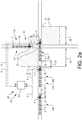
- Fig. 2a shows a transportation system 20 which comprises a first set 21a of vehicle platoons and a second set 21b of vehicle platoons driving in a road network 22.
- the first set 21a of vehicle platoons may comprise two or more vehicle platoons, preferably several vehicle platoons.
- the second set 21b of vehicle platoons may comprise one or more vehicle platoons, preferably several vehicle platoons.
- three vehicle platoons 26a, 26b, 26c of the first set 21a of vehicle platoons are illustrated, and one vehicle platoon 27 of the second set 21b of vehicle platoons is illustrated.
- Each of the vehicle platoons has a lead vehicle 2, 2a, 2b, 2c and a plurality of vehicles 3 following the lead vehicle as described hereinabove.
- the transportation system 20 further comprises a control system 40 configured to control the first set 21a of vehicle platoons driving along a first road 23 and the second set 21b of vehicle platoons driving along a second road 24.
- the first road 23 and the second road 24 of the road network 22 cross each other such that an intersection 25 is formed.
- the intersection 25 constitutes a road section in common to the first road 23 and the second road 24.
- This road section comprises an intersection point 25a.
- the first set 21a of vehicle platoons are driving in a first direction 8a (from left to right) towards the intersection 25, and the second set 21b of vehicle platoons are driving in a second substantially perpendicular direction 8b (top to bottom) towards the intersection 25.
- the operation of the transportation system 20 described herein is preferably performed by controlling the vehicle platoons by means of the equipment and control units described herein, without any assistance from any driver of any of the vehicles.
- a method for operating a transportation system comprising a first set of vehicle platoons and a second set of vehicle platoons, will be described with reference to Figs. 2a , 2b , 2c and Fig. 3 .
- the first and second sets of vehicle platoons are illustrated at different time points.
- the method comprises the steps of controlling the vehicle platoons by means of the control system 40, driving the first set 21a of vehicle platoons along the first road 23 and the second set 21b of vehicle platoons along the second road 24, increasing the distance, at the intersection 25, between a first vehicle platoon 26a and a following second vehicle platoon 26b of the first set 21a of vehicle platoons driving along the first road 23, and controlling a vehicle platoon 27 of the second set 21b of vehicle platoons driving along the second road 24 to pass the intersection 25 in the gap between the last vehicle 28 of the first vehicle platoon 26a and the lead vehicle 2b of the second vehicle platoon 26b.
- the following second vehicle platoon 26b is the first next vehicle platoon after the first vehicle platoon 26a.
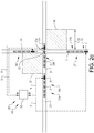
- the gap or distance between the first vehicle platoon 26a and the second vehicle platoon 26b, i.e. between the last vehicle 28 of the first vehicle platoon 26a and the lead vehicle 2b of the second vehicle platoon 26b, is indicated with "D1". Both the distance and the time gap between the vehicle platoons can be increased at the intersection 25. The time gap is determined by the distance between the vehicle platoons and the speed of the vehicle platoons.
- the first vehicle platoon 26a has reached the intersection 25 and the lead vehicle 2a of the first vehicle platoon 26a has entered and just passed the intersection 25.
- the speed of the first vehicle platoon 26a can be increased for increasing the distance D1 between the first vehicle platoon 26a and the second vehicle platoon 26b at the intersection 25.
- the speed of the first vehicle platoon 26a can be increased from a pre-intersection speed before the intersection 25 to a post-intersection speed after the intersection 25.
- the post-intersection speed of the first vehicle platoon 26a can be maintained until the lead vehicle 2a of the first vehicle platoon 26a is at a predetermined distance 29 after the intersection 25, and thereafter the speed of the first vehicle platoon 26a can be changed to a driving speed.
- the post-intersection speed of the first vehicle platoon 26a can be maintained until the last vehicle 28 of the first vehicle platoon 26a has passed the intersection 25, and thereafter the speed of the first vehicle platoon 26a can be changed to the driving speed.
- the speed of the second vehicle platoon 26b can be decreased before the lead vehicle 2b of the second vehicle platoon 26b has reached the intersection 25, for increasing the distance D1 between the first vehicle platoon 26a and the second vehicle platoon 26b at the intersection 25.
- the speed of the second vehicle platoon 26b can be decreased when the lead vehicle 2b of the second vehicle platoon 26b is at a predetermined distance 30 before the intersection 25.
- the speed of the second vehicle platoon 26b can be decreased from the driving speed to the pre-intersection speed.
- the pre-intersection speed of the second vehicle platoon 26b is suitably maintained until the lead vehicle 2b of the second vehicle platoon 26b has entered the intersection 25.
- the first vehicle platoon 26a is driven with an increased speed along the predetermined distance 29 after the intersection 25, and the second vehicle platoon 26b is driven with a decreased speed along the predetermined distance 30 before the intersection 25, which means that the distance D1 between the first vehicle platoon 26a and the second vehicle platoon 26b is increased at the intersection 25.
- the distance between the first vehicle platoon is represented by "D1”
- the distance is represented by "D2”, where D2>D1.
- the gap or distance D2 will comprise the intersection position of the first road 23 and the second road 24 when the vehicle platoon 27 of the second set 21b of vehicle platoons driving along the second road 24 is passing the intersection 25 in the gap.
- the first vehicle platoon 26a can be driven with a normal driving speed after the section where the first vehicle platoon has the post-intersection speed
- the second vehicle platoon 26b can be driven with a normal driving speed before the section where the second vehicle platoon has the pre-intersection speed.
- the normal driving speed outside the sections closest to the intersection 25 can be the same for the vehicle platoons, suitably a constant speed.
- the speeds can be selected such that the post-intersection speed is higher than the normal driving speed which in turn is higher than the pre-intersection speed.
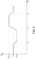
- Fig. 3 shows a graph illustrating an example of vehicle platoon speed "V" versus vehicle platoon position "X".
- the speed is decreased from the driving speed V D to the pre-intersection speed V PRE , and at the intersection 25, the speed is increased from the pre-intersection speed V PRE to the post-intersection speed V POST , and finally at point 33, the speed is decreased to the driving speed V D . See also Fig. 2a .
- the speed of the second vehicle platoon 26b can be increased when the lead vehicle 2b of the second vehicle platoon 26b has entered the intersection 25. See Fig. 2c .
- the speed of the second vehicle platoon 26b can be increased from the pre-intersection speed before the intersection 25 to a post-intersection speed after the intersection 25, and the post-intersection speed of the second vehicle platoon 26b can be maintained until the lead vehicle 2b of the second vehicle platoon 26b is at a predetermined distance 29 after the intersection 25 or until the last vehicle 31 of the second vehicle platoon 26b has passed the intersection 25, and thereafter the speed of the second vehicle platoon 26b can be changed to a driving speed.
- the procedure can be repeated for each vehicle platoon of the first set 21a of vehicle platoons for enabling a further vehicle platoon 34 of the second set 21b of vehicle platoons to pass the intersection 25 in a gap between two consecutive vehicle platoons of the first set 21a of vehicle platoons. Further, in Fig. 2c , the entire vehicle platoon 27 of the second set 21b of vehicle platoons has passed the intersection 25.
- the vehicle platoon 27 (hereinafter called the further vehicle platoon) of the second set 21b of vehicle platoons driving along the second road 24 is controlled to pass the intersection 25 in the gap D2 between the last vehicle 28 of the first vehicle platoon 26a and the lead vehicle 2b of the second vehicle platoon 26b.
- Fig. 2b the lead vehicle 2 of the further vehicle platoon 27 has reached and passed the intersection 25.
- the speed of the further vehicle platoon 27 can be increased.
- the speed of the further vehicle platoon 27 can be increased.
- the second set 21b of vehicle platoons can be driven in the same way as the first set 21a of vehicle platoons, using a pre-intersection speed before the intersection 25 and a post-intersection speed after the intersection 25, and suitably a normal driving speed outside the sections closest to intersection 25.
- the flow of vehicle platoons passing the intersection 25 along the first road 23 and the flow of vehicle platoons passing the intersection 25 along the second road 24, can be synchronized such that alternating a vehicle platoon on the first road 23 and a vehicle platoon on the second road 24 will pass the intersection 25.
- two vehicle platoon speed zones 35, 36 can be used.
- the size of such a zone and the speed increase and/or speed decrease used are adapted to the distance and time gap between the vehicle platoons required for enabling a vehicle platoon on one road to pass the intersection between two consecutive vehicle platoons on the other road.
- a shorter zone will require a relatively high speed change and a longer zone will require a relatively low speed change.
- the invention also relates to a control system 40 for controlling a transportation system 20 comprising a first set 21a of vehicle platoons and a second set 21b of vehicle platoons, where each of the vehicle platoons has a lead vehicle and a plurality of vehicles following the lead vehicle.
- the control system is configured to control the first set 21a of vehicle platoons driving along a first road 23 and the second set of vehicle platoons 21b driving along a second road 24.
- the control unit is configured to increase the distance, at the intersection, between a first vehicle platoon 26a and a following second vehicle platoon 26b of the first set 21a of vehicle platoons driving along the first road 23, and to control a vehicle platoon 27 of the second set 21b of vehicle platoons driving along the second road 24 to pass the intersection 25 in the gap between the last vehicle 28 of the first vehicle platoon 26a and the lead vehicle 2b of the second vehicle platoon 26b.
- the vehicle platoons can be synchronized before reaching the intersection 25 enabling the first vehicle platoon 26a, the vehicle platoon 27 of the second set 21b of vehicle platoons, and the second vehicle platoon 26b, to pass the intersection 25 one at the time in this order.
- the control system 40 can be used for controlling the vehicle platoons in accordance with any of the example embodiments described herein.
- the control system 40 can suitably comprise one or more central control units 10 and/or one or more of the local control units 5, which units can be used individually and in cooperation.
- the control system 40 comprises a central control unit 10.
- the central control unit 10 is configured and arranged to communicate 9 with the vehicle platoons 26a, 26b, 26c, 27, preferably with the control unit 5 of the lead vehicle of each vehicle platoon, for controlling the driving of the vehicle platoons.
- the central control unit 10 and the local control unit 5 arranged on a vehicle may comprise one or more microprocessors and/or one or more memory devices or any other components for mutual communication, and for communicating with other equipment.
- the vehicle platoons can be controlled, and particularly computer programs to perform the method described herein can be executed.
- the central control unit and/or the local control unit is preferably provided with a computer program comprising program code means for performing the steps of any example embodiment of the method described herein.
- control system may comprise a decentralized network of computers not necessarily arranged in one and the same central control unit.
- sensors can be arranged in the environment to the current road where the vehicle platoons are driven. These sensors may provide information received by the control system. Such sensors could be a complement to the sensors of the vehicles for instance, giving further information and/or redundancy to the system.
Landscapes
- Engineering & Computer Science (AREA)
- Automation & Control Theory (AREA)
- Transportation (AREA)
- Mechanical Engineering (AREA)
- Physics & Mathematics (AREA)
- General Physics & Mathematics (AREA)
- Control Of Driving Devices And Active Controlling Of Vehicle (AREA)
- Traffic Control Systems (AREA)
Abstract
Description
- The invention relates to a method for operating a transportation system and a control system for controlling vehicles of a transportation system.
- Today's transportation or traffic systems for transporting passengers have a relatively low capacity and public transport timetables often cannot be kept without delays. One way of trying to increase the capacity of the total traffic flow is to organize the vehicles in vehicle platoons, where each vehicle platoon has a lead vehicle and a plurality of following vehicles driving in a convoy after the lead vehicle.
- There is however still a need for optimizing the use of such vehicle platoons and enabling vehicle platoons to pass intersections of a road network in an effective way for providing a relatively high throughput of vehicle platoons.
- An objective of the invention is to provide a method for operating a transportation system, by which method the throughput of vehicle platoons through an intersection of a road network can be increased.
- The objective is achieved by a method for operating a transportation system comprising a first set of vehicle platoons and a second set of vehicle platoons, where each of the vehicle platoons has a lead vehicle and a plurality of vehicles following the lead vehicle, and the method comprises the steps of controlling the vehicle platoons by means of a control system, driving the first set of vehicle platoons along a first road and the second set of vehicle platoons along a second road, wherein the first road and the second road cross each other forming an intersection, and increasing the distance, at the intersection, between a first vehicle platoon and a following second vehicle platoon of the first set of vehicle platoons driving along the first road, and controlling a vehicle platoon of the second set of vehicle platoons driving along the second road to pass the intersection in the gap between the last vehicle of the first vehicle platoon and the lead vehicle of the second vehicle platoon.
- The invention is based on the insight that by such a method, it is possible to provide a relatively high flow of vehicle platoons through an intersection of a road network. By use of the control system for synchronization of the vehicle platoons, the time gap between the vehicle platoons can be minimized and the driving can be planned for maintaining a relative high speed and avoiding any stoppage of any vehicle platoon. The time, speed and position of the vehicle platoons can be synchronized by the control system. This will also save energy since the deceleration and acceleration of the vehicle platoons required for passing the intersection, can be minimized.
- According to one embodiment of the method, the method comprises the step of increasing the speed of the first vehicle platoon when the lead vehicle of the first vehicle platoon has entered the intersection, and/or decreasing the speed of the second vehicle platoon before the lead vehicle of the second vehicle platoon has reached the intersection. Hereby, the distance between the first vehicle platoon and the second vehicle platoon can be temporarily increased when passing the intersection, making it possible for another vehicle platoon driving along a crossing road to pass the intersection in an efficient and safe way in the gap between the first vehicle platoon and the second vehicle platoon. Before and after the intersection, the vehicle platoons can be driven with another optimized distance and time gap.
- According to a further embodiment of the method, the method comprises the step of increasing the speed of the first vehicle platoon from a pre-intersection speed before the intersection to a post-intersection speed after the intersection. By selecting the difference between the pre-intersection speed and the post-intersection speed based on the frequency of vehicle platoons along the road, the distance and time gap between the first vehicle platoon and the second vehicle platoon driving along the first road can be adapted to the length and speed of the vehicle platoon driving along the second road. For example, the pre-intersection speed is suitably lower than the driving speed used before when the vehicle platoon approaches the intersection, and the post-intersection speed used immediately after the intersection is suitably higher than the driving speed used thereafter.
- According to a further embodiment of the method, the method comprises the step of maintaining the post-intersection speed of the first vehicle platoon until the lead vehicle of the first vehicle platoon is at a predetermined distance after the intersection, and thereafter changing the speed of the first vehicle platoon to a driving speed. Hereby, it can be ensured that the distance and time gap will be sufficient for allowing the crossing vehicle platoon driving along the second road to pass the intersection.
- According to a further embodiment of the method, the method comprises the step of maintaining the post-intersection speed of the first vehicle platoon until the last vehicle of the first vehicle platoon has passed the intersection, and thereafter changing the speed of the first vehicle platoon to a driving speed. Hereby, it can be ensured that the distance and time gap will be sufficient for allowing the crossing vehicle platoon driving along the second road to pass the intersection.
- According to a further embodiment of the method, the method comprises the step of decreasing the speed of the second vehicle platoon when the lead vehicle of the second vehicle platoon is at a predetermined distance before the intersection. Hereby, it can be ensured that the distance and time gap will be sufficient for allowing the crossing vehicle platoon driving along the second road to pass the intersection.
- According to a further embodiment of the method, the method comprises the step of decreasing the speed of the second vehicle platoon from a driving speed to a pre-intersection speed. Hereby, it can be ensured that the distance and time gap will be sufficient for allowing the crossing vehicle platoon driving along the second road to pass the intersection.
- According to a further embodiment of the method, the method comprises the step of maintaining the pre-intersection speed of the second vehicle platoon until the lead vehicle of the second vehicle platoon has entered the intersection. Hereby, it can be ensured that the distance and time gap will be sufficient for allowing the crossing vehicle platoon driving along the second road to pass the intersection.
- According to a further embodiment of the method, the method comprises the step of increasing the speed of the second vehicle platoon when the lead vehicle of the second vehicle platoon has entered the intersection. Hereby, the distance between the second vehicle platoon and a further following vehicle platoon can be temporarily increased when passing the intersection, making it possible for a further vehicle platoon driving along a crossing road to pass the intersection in an efficient and safe way in the gap between the second vehicle platoon and the further following vehicle platoon. Before and after the intersection, the vehicle platoons can be driven with another optimized distance and time gap.
- According to a further embodiment of the method, the method comprises the step of increasing the speed of the second vehicle platoon from the pre-intersection speed before the intersection to a post-intersection speed after the intersection. By selecting the difference between the pre-intersection speed and the post-intersection speed based on the frequency of vehicle platoons along the road, the distance and time gap between the second vehicle platoon and a further following vehicle platoon driving along the first road can be adapted to the length and speed of a further vehicle platoon driving along the second road. For example, the pre-intersection speed is suitably lower than the driving speed used before when the vehicle platoon approaches the intersection, and the post-intersection speed used immediately after the intersection is suitably higher than the driving speed used thereafter.
- According to a further embodiment of the method, the method comprises the step of maintaining the post-intersection speed of the second vehicle platoon until the lead vehicle of the second vehicle platoon is at a predetermined distance after the intersection, and thereafter changing the speed of the second vehicle platoon to a driving speed. Hereby, it can be ensured that the distance and time gap will be sufficient for allowing the crossing vehicle platoon driving along the second road to pass the intersection.
- According to a further embodiment of the method, the method comprises the step of maintaining the post-intersection speed of the second vehicle platoon until the last vehicle of the second vehicle platoon has passed the intersection, and thereafter changing the speed of the second vehicle platoon to a driving speed. Hereby, it can be ensured that the distance and time gap will be sufficient for allowing the crossing vehicle platoon driving along the second road to pass the intersection.
- According to a further aspect of the invention, a further objective of the invention is to provide a control system for controlling vehicles of a transportation system, by which control system the throughput of vehicle platoons through an intersection of a road network can be increased.
- The objective is achieved by a control system for controlling vehicles of a transportation system comprising a first set of vehicle platoons and a second set of vehicle platoons, where each of the vehicle platoons has a lead vehicle and a plurality of vehicles following the lead vehicle, and the control system is configured to control the first set of vehicle platoons driving along a first road and the second set of vehicle platoons driving along a second road, wherein the first road and the second road cross each other forming an intersection, and the control unit is configured to increase the distance, at the intersection, between a first vehicle platoon and a following second vehicle platoon of the first set of vehicle platoons driving along the first road, and to control a vehicle platoon of the second set of vehicle platoons driving along the second road to pass the intersection in the gap between the last vehicle of the first vehicle platoon and the lead vehicle of the second vehicle platoon.
- In addition, the invention relates to a transportation system comprising a first set of vehicle platoons and a second set of vehicle platoons, and such a control system. The invention also relates to a computer program comprising program code means for performing any method described herein.
- The advantages of the control system, the transportation system and the computer program are similar to the advantages already discussed hereinabove with reference to some embodiments of the method.
- Further advantages and advantageous features of the invention are disclosed in the following description and in the claims.
- With reference to the appended drawings, below follows a more detailed description of embodiments of the invention cited as examples.
- In the drawings:
-
Fig. 1 shows a vehicle platoon, -
Fig. 2a shows a transportation system with a first set of vehicle platoons and a second set of vehicle platoons at an intersection, and a control system for controlling the vehicle platoons, -
Fig. 2b shows the transportation system illustrated inFig. 2a , where the first set of vehicle platoons and the second set of vehicle platoons have been moved relative to the intersection, -
Fig. 2c shows the transportation system illustrated inFig. 2a , where the first set of vehicle platoons and the second set of vehicle platoons have been further moved relative to the intersection, and -
Fig. 3 shows a graph illustrating vehicle platoon speed versus vehicle platoon position. -
Fig. 1 shows avehicle platoon 1 having alead vehicle 2 and a plurality of followingvehicles 3. Thelead vehicle 2 and the followingvehicles 3 are individual vehicles but driven together as a group or convoy. The followingvehicles 3 are positioned in a line after thelead vehicle 2. The driving direction is indicated with an arrow 8. Thelead vehicle 2 can be a so called autonomous or self-driving vehicle, or thelead vehicle 2 can be at least partly controlled by an operator of the lead vehicle. The followingvehicles 3 of the vehicle platoon are suitably automatically controlled without any driver assistance. The vehicle platoon is suitably used for transportation of passengers of the vehicles, though the vehicles can also be used for transporting goods. - When driving in the
vehicle platoon 1, the followingvehicles 3 are controlled to follow thelead vehicle 2 or the vehicle closest to the front, such that when the speed of thelead vehicle 2 is increased/decreased the speed of the followingvehicles 3 is increased/decreased correspondingly for maintaining or achieving the desired distances and time gaps between the vehicles. Further, when thelead vehicle 2 is changing driving direction, a followingvehicle 3 will also change driving direction and follow the lead vehicle or rather the vehicle closest to the front. - For enabling the
vehicles suitable sensor equipment 4 for receiving information about the environment, and acontrol unit 5 for controlling the vehicle. The sensor equipment gives information about at least the vehicle closest to the front, but preferably the sensor equipment is covering 360 degrees around the vehicle for obtaining the information that is required for longitudinal and lateral control of the vehicle.Such sensor equipment 4 may comprise lidar, radar and ultrasonic sensors, cameras, etc. The information received by the sensor equipment is used by thecontrol unit 5 for controlling the driving behaviour of the vehicle. In addition, maps, GPS, etc., can be used for determining the current position of a vehicle platoon or an individual vehicle of a vehicle platoon. - Alternatively or in addition to the
sensor equipment 4, eachvehicle communication unit 6 for communicating with one or more of the other vehicles of thevehicle platoon 1. Such acommunication unit 6 may comprise any suitable components for establish communication between the vehicles. For example, thecommunication unit 6 may comprise a transmitter and a receiver based on radio waves or microwaves. In other words, each vehicle can be part of a local network forcommunication 7 between the vehicles of thevehicle platoon 1. By means of the local network, control signals can be transmitted from one vehicle to another vehicle. The control signals received are then used by thecontrol unit 5 arranged on the vehicle for controlling the driving behaviour of the vehicle. Such control signals received by the followingvehicles 3 are preferably at least initially provided by thelead vehicle 2. - Such a
vehicle platoon 1 of a transportation system is suitably part of a central network forcommunication 9 between thevehicle platoon 1 and acentral control unit 10. By means of the central network, control signals can be transmitted from thecentral control unit 10 to thevehicle platoon 1 for controlling the driving behaviour of the vehicle platoon. Such control signals are preferably received by thelead vehicle 2 of the vehicle platoon, but could also be received by one or more of the followingvehicles 3 of the vehicle platoon. Thecentral control unit 10 can be part of a server of a wireless network, such as Internet, for cloud computing. -
Fig. 2a shows atransportation system 20 which comprises afirst set 21a of vehicle platoons and asecond set 21b of vehicle platoons driving in aroad network 22. Thefirst set 21a of vehicle platoons may comprise two or more vehicle platoons, preferably several vehicle platoons. Thesecond set 21b of vehicle platoons may comprise one or more vehicle platoons, preferably several vehicle platoons. InFig. 2a , as an example only, threevehicle platoons first set 21a of vehicle platoons are illustrated, and onevehicle platoon 27 of thesecond set 21b of vehicle platoons is illustrated. Each of the vehicle platoons has alead vehicle vehicles 3 following the lead vehicle as described hereinabove. - The
transportation system 20 further comprises acontrol system 40 configured to control thefirst set 21a of vehicle platoons driving along afirst road 23 and thesecond set 21b of vehicle platoons driving along asecond road 24. - The
first road 23 and thesecond road 24 of theroad network 22 cross each other such that anintersection 25 is formed. Theintersection 25 constitutes a road section in common to thefirst road 23 and thesecond road 24. This road section comprises anintersection point 25a. In the example embodiment shown inFig. 2a , thefirst set 21a of vehicle platoons are driving in a first direction 8a (from left to right) towards theintersection 25, and thesecond set 21b of vehicle platoons are driving in a second substantiallyperpendicular direction 8b (top to bottom) towards theintersection 25. - It should be stressed that the operation of the
transportation system 20 described herein is preferably performed by controlling the vehicle platoons by means of the equipment and control units described herein, without any assistance from any driver of any of the vehicles. - A method for operating a transportation system comprising a first set of vehicle platoons and a second set of vehicle platoons, will be described with reference to
Figs. 2a ,2b ,2c andFig. 3 . In the figures, the first and second sets of vehicle platoons are illustrated at different time points. - The method comprises the steps of controlling the vehicle platoons by means of the
control system 40, driving thefirst set 21a of vehicle platoons along thefirst road 23 and thesecond set 21b of vehicle platoons along thesecond road 24, increasing the distance, at theintersection 25, between afirst vehicle platoon 26a and a followingsecond vehicle platoon 26b of thefirst set 21a of vehicle platoons driving along thefirst road 23, and controlling avehicle platoon 27 of thesecond set 21b of vehicle platoons driving along thesecond road 24 to pass theintersection 25 in the gap between thelast vehicle 28 of thefirst vehicle platoon 26a and thelead vehicle 2b of thesecond vehicle platoon 26b. The followingsecond vehicle platoon 26b is the first next vehicle platoon after thefirst vehicle platoon 26a. - In
Fig. 2a , the gap or distance between thefirst vehicle platoon 26a and thesecond vehicle platoon 26b, i.e. between thelast vehicle 28 of thefirst vehicle platoon 26a and thelead vehicle 2b of thesecond vehicle platoon 26b, is indicated with "D1". Both the distance and the time gap between the vehicle platoons can be increased at theintersection 25. The time gap is determined by the distance between the vehicle platoons and the speed of the vehicle platoons. - As also illustrated, the
first vehicle platoon 26a has reached theintersection 25 and thelead vehicle 2a of thefirst vehicle platoon 26a has entered and just passed theintersection 25. In a position, when thelead vehicle 2a of thefirst vehicle platoon 26a has entered theintersection 25, the speed of thefirst vehicle platoon 26a can be increased for increasing the distance D1 between thefirst vehicle platoon 26a and thesecond vehicle platoon 26b at theintersection 25. The speed of thefirst vehicle platoon 26a can be increased from a pre-intersection speed before theintersection 25 to a post-intersection speed after theintersection 25. The post-intersection speed of thefirst vehicle platoon 26a can be maintained until thelead vehicle 2a of thefirst vehicle platoon 26a is at apredetermined distance 29 after theintersection 25, and thereafter the speed of thefirst vehicle platoon 26a can be changed to a driving speed. Alternatively, the post-intersection speed of thefirst vehicle platoon 26a can be maintained until thelast vehicle 28 of thefirst vehicle platoon 26a has passed theintersection 25, and thereafter the speed of thefirst vehicle platoon 26a can be changed to the driving speed. - Further, the speed of the
second vehicle platoon 26b can be decreased before thelead vehicle 2b of thesecond vehicle platoon 26b has reached theintersection 25, for increasing the distance D1 between thefirst vehicle platoon 26a and thesecond vehicle platoon 26b at theintersection 25. The speed of thesecond vehicle platoon 26b can be decreased when thelead vehicle 2b of thesecond vehicle platoon 26b is at apredetermined distance 30 before theintersection 25. The speed of thesecond vehicle platoon 26b can be decreased from the driving speed to the pre-intersection speed. The pre-intersection speed of thesecond vehicle platoon 26b is suitably maintained until thelead vehicle 2b of thesecond vehicle platoon 26b has entered theintersection 25. - In the example embodiment illustrated in
Fig. 2a ,2b and2c , thefirst vehicle platoon 26a is driven with an increased speed along thepredetermined distance 29 after theintersection 25, and thesecond vehicle platoon 26b is driven with a decreased speed along thepredetermined distance 30 before theintersection 25, which means that the distance D1 between thefirst vehicle platoon 26a and thesecond vehicle platoon 26b is increased at theintersection 25. InFig. 2a , the distance between the first vehicle platoon is represented by "D1", whereas inFig. 2b , the distance is represented by "D2", where D2>D1. The gap or distance D2 will comprise the intersection position of thefirst road 23 and thesecond road 24 when thevehicle platoon 27 of thesecond set 21b of vehicle platoons driving along thesecond road 24 is passing theintersection 25 in the gap. - The
first vehicle platoon 26a can be driven with a normal driving speed after the section where the first vehicle platoon has the post-intersection speed, and thesecond vehicle platoon 26b can be driven with a normal driving speed before the section where the second vehicle platoon has the pre-intersection speed. The normal driving speed outside the sections closest to theintersection 25 can be the same for the vehicle platoons, suitably a constant speed. The speeds can be selected such that the post-intersection speed is higher than the normal driving speed which in turn is higher than the pre-intersection speed. -
Fig. 3 shows a graph illustrating an example of vehicle platoon speed "V" versus vehicle platoon position "X". Atpoint 32, the speed is decreased from the driving speed VD to the pre-intersection speed VPRE, and at theintersection 25, the speed is increased from the pre-intersection speed VPRE to the post-intersection speed VPOST, and finally atpoint 33, the speed is decreased to the driving speed VD. See alsoFig. 2a . - For creating an increased distance between the
second vehicle platoon 26b and a followingthird vehicle platoon 26c of thefirst set 21a of vehicle platoons, the speed of thesecond vehicle platoon 26b can be increased when thelead vehicle 2b of thesecond vehicle platoon 26b has entered theintersection 25. SeeFig. 2c . In the same way as previously described for thefirst vehicle platoon 26a, the speed of thesecond vehicle platoon 26b can be increased from the pre-intersection speed before theintersection 25 to a post-intersection speed after theintersection 25, and the post-intersection speed of thesecond vehicle platoon 26b can be maintained until thelead vehicle 2b of thesecond vehicle platoon 26b is at apredetermined distance 29 after theintersection 25 or until thelast vehicle 31 of thesecond vehicle platoon 26b has passed theintersection 25, and thereafter the speed of thesecond vehicle platoon 26b can be changed to a driving speed. In other words; the procedure can be repeated for each vehicle platoon of thefirst set 21a of vehicle platoons for enabling afurther vehicle platoon 34 of thesecond set 21b of vehicle platoons to pass theintersection 25 in a gap between two consecutive vehicle platoons of thefirst set 21a of vehicle platoons. Further, inFig. 2c , theentire vehicle platoon 27 of thesecond set 21b of vehicle platoons has passed theintersection 25. - As previously mentioned with reference to
Fig. 2b , the vehicle platoon 27 (hereinafter called the further vehicle platoon) of thesecond set 21b of vehicle platoons driving along thesecond road 24 is controlled to pass theintersection 25 in the gap D2 between thelast vehicle 28 of thefirst vehicle platoon 26a and thelead vehicle 2b of thesecond vehicle platoon 26b. - In
Fig. 2b , thelead vehicle 2 of thefurther vehicle platoon 27 has reached and passed theintersection 25. For shorten the time required for thefurther vehicle platoon 27 to pass theintersection 25 in the gap D2 between thefirst vehicle platoon 26a and thesecond vehicle platoon 26b, the speed of thefurther vehicle platoon 27 can be increased. In analogy with what has been described for thefirst vehicle platoon 26a, when thelead vehicle 2 of thefurther vehicle platoon 27 has entered theintersection 25, the speed of thefurther vehicle platoon 27 can be increased. In fact, thesecond set 21b of vehicle platoons can be driven in the same way as thefirst set 21a of vehicle platoons, using a pre-intersection speed before theintersection 25 and a post-intersection speed after theintersection 25, and suitably a normal driving speed outside the sections closest tointersection 25. - The flow of vehicle platoons passing the
intersection 25 along thefirst road 23 and the flow of vehicle platoons passing theintersection 25 along thesecond road 24, can be synchronized such that alternating a vehicle platoon on thefirst road 23 and a vehicle platoon on thesecond road 24 will pass theintersection 25. - As also indicated in
Fig. 2a , for example two vehicleplatoon speed zones low speed zone 35 before the intersection (relative to the driving directions of the vehicle platoons) used for both the first set of vehicle platoons and the second set of vehicle platoons, which zone can be seen at top left closest to theintersection 25 inFig. 2a , and/or ahigh speed zone 36 after the intersection (relative to the driving directions of the vehicle platoons) used for both the first set of vehicle platoons and the second set of vehicle platoons, which zone can be seen below right closest to theintersection 25 inFig. 2a . - The size of such a zone and the speed increase and/or speed decrease used, are adapted to the distance and time gap between the vehicle platoons required for enabling a vehicle platoon on one road to pass the intersection between two consecutive vehicle platoons on the other road. A shorter zone will require a relatively high speed change and a longer zone will require a relatively low speed change.
- With further reference to
Fig. 2a , the invention also relates to acontrol system 40 for controlling atransportation system 20 comprising afirst set 21a of vehicle platoons and asecond set 21b of vehicle platoons, where each of the vehicle platoons has a lead vehicle and a plurality of vehicles following the lead vehicle. The control system is configured to control thefirst set 21a of vehicle platoons driving along afirst road 23 and the second set of vehicle platoons 21b driving along asecond road 24. The control unit is configured to increase the distance, at the intersection, between afirst vehicle platoon 26a and a followingsecond vehicle platoon 26b of thefirst set 21a of vehicle platoons driving along thefirst road 23, and to control avehicle platoon 27 of thesecond set 21b of vehicle platoons driving along thesecond road 24 to pass theintersection 25 in the gap between thelast vehicle 28 of thefirst vehicle platoon 26a and thelead vehicle 2b of thesecond vehicle platoon 26b. - The vehicle platoons can be synchronized before reaching the
intersection 25 enabling thefirst vehicle platoon 26a, thevehicle platoon 27 of thesecond set 21b of vehicle platoons, and thesecond vehicle platoon 26b, to pass theintersection 25 one at the time in this order. - The
control system 40 can be used for controlling the vehicle platoons in accordance with any of the example embodiments described herein. - The
control system 40 can suitably comprise one or morecentral control units 10 and/or one or more of thelocal control units 5, which units can be used individually and in cooperation. - In the example embodiment illustrated in
Fig. 2a , thecontrol system 40 comprises acentral control unit 10. Thecentral control unit 10 is configured and arranged to communicate 9 with the vehicle platoons 26a, 26b, 26c, 27, preferably with thecontrol unit 5 of the lead vehicle of each vehicle platoon, for controlling the driving of the vehicle platoons. - The
central control unit 10 and thelocal control unit 5 arranged on a vehicle may comprise one or more microprocessors and/or one or more memory devices or any other components for mutual communication, and for communicating with other equipment. By means of the control units, the vehicle platoons can be controlled, and particularly computer programs to perform the method described herein can be executed. Thus, the central control unit and/or the local control unit is preferably provided with a computer program comprising program code means for performing the steps of any example embodiment of the method described herein. - Optionally, the control system may comprise a decentralized network of computers not necessarily arranged in one and the same central control unit.
- Alternatively or in addition to what has been described hereinabove, sensors can be arranged in the environment to the current road where the vehicle platoons are driven. These sensors may provide information received by the control system. Such sensors could be a complement to the sensors of the vehicles for instance, giving further information and/or redundancy to the system.
- It is to be understood that the present invention is not limited to the embodiments described above and illustrated in the drawings; rather, the skilled person will recognize that many changes and modifications may be made within the scope of the appended claims.
Claims (15)
- A method for operating a transportation system (20) comprising a first set (21a) of vehicle platoons and a second set (21b) of vehicle platoons, each of the vehicle platoons having a lead vehicle (2, 2a, 2b) and a plurality of vehicles (3) following the lead vehicle, the method comprising the steps of controlling the vehicle platoons by means of a control system (40), driving the first set (21a) of vehicle platoons along a first road (23) and the second set (21b) of vehicle platoons along a second road (24), the first road and the second road crossing each other forming an intersection (25), increasing the distance, at the intersection, between a first vehicle platoon (26a) and a following second vehicle platoon (26b) of the first set (21a) of vehicle platoons driving along the first road (23), and controlling a vehicle platoon (27) of the second set (21b) of vehicle platoons driving along the second road (24) to pass the intersection (25) in the gap between the last vehicle (28) of the first vehicle platoon (26a) and the lead vehicle (2b) of the second vehicle platoon (26b).
- A method according to claim 1, characterized by increasing the speed of the first vehicle platoon (26a) when the lead vehicle (2a) of the first vehicle platoon has entered the intersection (25), and/or decreasing the speed of the second vehicle platoon (26b) before the lead vehicle (2b) of the second vehicle platoon has reached the intersection (25).
- A method according to claim 2, characterized by increasing the speed of the first vehicle platoon (26a) from a pre-intersection speed before the intersection (25) to a post-intersection speed after the intersection (25).
- A method according to claim 3, characterized by maintaining the post-intersection speed of the first vehicle platoon (26a) until the lead vehicle (2a) of the first vehicle platoon is at a predetermined distance (29) after the intersection (25), and thereafter changing the speed of the first vehicle platoon (26a) to a driving speed.
- A method according to claim 3, characterized by maintaining the post-intersection speed of the first vehicle platoon (26a) until the last vehicle (28) of the first vehicle platoon has passed the intersection (25), and thereafter changing the speed of the first vehicle platoon (26a) to a driving speed.
- A method according to any of claims 2-5, characterized by decreasing the speed of the second vehicle platoon (26b) when the lead vehicle (2b) of the second vehicle platoon is at a predetermined distance (30) before the intersection (25).
- A method according to any of claims 2-6, characterized by decreasing the speed of the second vehicle platoon (26b) from a driving speed to a pre-intersection speed.
- A method according to claim 7, characterized by maintaining the pre-intersection speed of the second vehicle platoon (26b) until the lead vehicle (2b) of the second vehicle platoon has entered the intersection (25).
- A method according to any of claims 1-8, characterized by increasing the speed of the second vehicle platoon (26b) when the lead vehicle (2b) of the second vehicle platoon has entered the intersection (25).
- A method according to claim 7 or 8, characterized by increasing the speed of the second vehicle platoon (26b) from the pre-intersection speed before the intersection to a post-intersection speed after the intersection (25).
- A method according to claim 10, characterized by maintaining the post-intersection speed of the second vehicle platoon (26b) until the lead vehicle (2b) of the second vehicle platoon is at a predetermined distance (29) after the intersection (25), and thereafter changing the speed of the second vehicle platoon (26b) to a driving speed.
- A method according to claim 10, characterized by maintaining the post-intersection speed of the second vehicle platoon (26b) until the last vehicle (31) of the second vehicle platoon (26b) has passed the intersection (25), and thereafter changing the speed of the second vehicle platoon (26b) to a driving speed.
- A control system (40) for controlling vehicles of a transportation system (20) comprising a first set (21a) of vehicle platoons and a second set (21b) of vehicle platoons, each of the vehicle platoons having a lead vehicle (2, 2a, 2b) and a plurality of vehicles (3) following the lead vehicle, the control system (40) being configured to control the first set (21a) of vehicle platoons driving along a first road (23) and the second set (21b) of vehicle platoons driving along a second road (24), the first road and the second road crossing each other forming an intersection (25), the control system (40) being configured to increase the distance, at the intersection, between a first vehicle platoon (26a) and a following second vehicle platoon (26b) of the first set (21a) of vehicle platoons driving along the first road (23), and to control a vehicle platoon (27) of the second set (21b) of vehicle platoons driving along the second road (24) to pass the intersection (25) in the gap between the last vehicle (28) of the first vehicle platoon (26a) and the lead vehicle (2b) of the second vehicle platoon (26b).
- A control system according to claim 13, characterized in that the control system (40) is configured to increase the speed of the first vehicle platoon (26a) when the lead vehicle (2a) of the first vehicle platoon (26a) has entered the intersection (25), and/or to decrease the speed of the second vehicle platoon (26b) before the lead vehicle (2b) of the second vehicle platoon (26b) has reached the intersection (25).
- A transportation system (20) comprising a first set (21a) of vehicle platoons and a second set (21b) of vehicle platoons, each of the vehicle platoons having a lead vehicle (2, 2a, 2b) and a plurality of vehicles (3) following the lead vehicle, and a control system (40) configured to control the first set (21a) of vehicle platoons driving along a first road (23) and the second set (21b) of vehicle platoons driving along a second road (24), the first road and the second road crossing each other forming an intersection (25), the control system (40) being configured to increase the distance, at the intersection, between a first vehicle platoon (26a) and a following second vehicle platoon (26b) of the first set (21a) of vehicle platoons driving along the first road (23), and to control a vehicle platoon (27) of the second set (21b) of vehicle platoons driving along the second road (24) to pass the intersection (25) in the gap between the last vehicle (28) of the first vehicle platoon (26a) and the lead vehicle (2b) of the second vehicle platoon (26b).
Priority Applications (4)
| Application Number | Priority Date | Filing Date | Title |
|---|---|---|---|
| EP19214517.5A EP3836113A1 (en) | 2019-12-09 | 2019-12-09 | A method for operating a transportation system |
| PCT/CN2020/134643 WO2021115283A1 (en) | 2019-12-09 | 2020-12-08 | A method for operating a transportation system |
| CN202080083662.3A CN114787887B (en) | 2019-12-09 | 2020-12-08 | Method for operating a transport system |
| US17/831,794 US12039871B2 (en) | 2019-12-09 | 2022-06-03 | Method for operating a transportation system |
Applications Claiming Priority (1)
| Application Number | Priority Date | Filing Date | Title |
|---|---|---|---|
| EP19214517.5A EP3836113A1 (en) | 2019-12-09 | 2019-12-09 | A method for operating a transportation system |
Publications (1)
| Publication Number | Publication Date |
|---|---|
| EP3836113A1 true EP3836113A1 (en) | 2021-06-16 |
Family
ID=68840951
Family Applications (1)
| Application Number | Title | Priority Date | Filing Date |
|---|---|---|---|
| EP19214517.5A Withdrawn EP3836113A1 (en) | 2019-12-09 | 2019-12-09 | A method for operating a transportation system |
Country Status (4)
| Country | Link |
|---|---|
| US (1) | US12039871B2 (en) |
| EP (1) | EP3836113A1 (en) |
| CN (1) | CN114787887B (en) |
| WO (1) | WO2021115283A1 (en) |
Cited By (1)
| Publication number | Priority date | Publication date | Assignee | Title |
|---|---|---|---|---|
| CN115556749A (en) * | 2022-10-18 | 2023-01-03 | 上海洛轲智能科技有限公司 | Method, device and equipment for determining prediction time for adjusting following state |
Families Citing this family (2)
| Publication number | Priority date | Publication date | Assignee | Title |
|---|---|---|---|---|
| JP7509491B2 (en) * | 2020-06-11 | 2024-07-02 | 株式会社Subaru | Vehicle driving support device |
| EP4553807A1 (en) * | 2023-11-13 | 2025-05-14 | Nokia Solutions and Networks Oy | Traffic scheduling for intelligent transportation system |
Citations (8)
| Publication number | Priority date | Publication date | Assignee | Title |
|---|---|---|---|---|
| WO2010103504A1 (en) * | 2009-03-08 | 2010-09-16 | Yehuda Gore | System and method for controlling traffic by coordination of intersection approaching flows |
| CN102799146A (en) * | 2012-08-08 | 2012-11-28 | 成都乐创自动化技术股份有限公司 | Method for planning velocity of S-shaped acceleration and deceleration control for control system of numerical control equipment |
| CN104882008A (en) * | 2015-06-03 | 2015-09-02 | 东南大学 | Method for vehicle cooperative control at non-signaled intersection in vehicle networking environment |
| JP2016146130A (en) * | 2015-02-09 | 2016-08-12 | アイシン・エィ・ダブリュ株式会社 | Convoy traveling management device and convoy traveling management program |
| CN106935056A (en) * | 2017-04-28 | 2017-07-07 | 北京交通大学 | Intelligent crossroad cooperative control method based on critical gap theory |
| US20190051158A1 (en) * | 2018-03-30 | 2019-02-14 | Intel Corporation | Intelligent traffic management for vehicle platoons |
| US20190250639A1 (en) * | 2018-02-14 | 2019-08-15 | Here Global B.V. | Vehicle platoon system control for intersections |
| WO2019163262A1 (en) * | 2018-02-23 | 2019-08-29 | 住友電気工業株式会社 | Traffic signal control device, traffic signal control method, and computer program |
Family Cites Families (14)
| Publication number | Priority date | Publication date | Assignee | Title |
|---|---|---|---|---|
| US20070276600A1 (en) * | 2006-03-06 | 2007-11-29 | King Timothy I | Intersection collision warning system |
| JP2010186413A (en) | 2009-02-13 | 2010-08-26 | Mazda Motor Corp | Driving support apparatus for vehicle |
| JP5434863B2 (en) * | 2010-09-21 | 2014-03-05 | 株式会社豊田中央研究所 | Vehicle group operation management device and program |
| US8711005B2 (en) | 2010-12-27 | 2014-04-29 | Nicholas R. Musachio | Variable speed traffic control system |
| CN103177596B (en) * | 2013-02-25 | 2016-01-06 | 中国科学院自动化研究所 | A kind of intersection independent control system |
| DE102015016758A1 (en) * | 2015-12-23 | 2017-06-29 | Daimler Ag | Method for moving, in particular for controlling or regulating, a vehicle convoy |
| CN105702059B (en) * | 2016-04-12 | 2018-01-02 | 东南大学 | A kind of method for controlling traffic signal lights and system towards large-scale activity fleet |
| CN106875710B (en) * | 2017-01-24 | 2019-12-03 | 同济大学 | A self-organizing control method for intersections for networked autonomous vehicles |
| CN106846867A (en) * | 2017-03-29 | 2017-06-13 | 北京航空航天大学 | Signalized intersections green drives speed abductive approach and analogue system under a kind of car networking environment |
| CN106997674A (en) * | 2017-04-17 | 2017-08-01 | 青岛海信网络科技股份有限公司 | A kind of special duty's circuit traffic control method and device |
| CN107240252B (en) * | 2017-05-05 | 2019-10-11 | 长安大学 | An Active Vehicle Scheduling Method at an Intersection |
| JP6566179B1 (en) * | 2018-02-23 | 2019-08-28 | 住友電気工業株式会社 | Passability determination device, passage permission determination method, and computer program |
| CN108877268B (en) * | 2018-08-07 | 2021-05-25 | 南京大学 | An intelligent scheduling method for unmanned traffic light-free intersections |
| CN109410619B (en) | 2018-12-04 | 2021-09-10 | 清华大学 | Automatic traffic control method and system under one-way road network |
-
2019
- 2019-12-09 EP EP19214517.5A patent/EP3836113A1/en not_active Withdrawn
-
2020
- 2020-12-08 WO PCT/CN2020/134643 patent/WO2021115283A1/en not_active Ceased
- 2020-12-08 CN CN202080083662.3A patent/CN114787887B/en active Active
-
2022
- 2022-06-03 US US17/831,794 patent/US12039871B2/en active Active
Patent Citations (8)
| Publication number | Priority date | Publication date | Assignee | Title |
|---|---|---|---|---|
| WO2010103504A1 (en) * | 2009-03-08 | 2010-09-16 | Yehuda Gore | System and method for controlling traffic by coordination of intersection approaching flows |
| CN102799146A (en) * | 2012-08-08 | 2012-11-28 | 成都乐创自动化技术股份有限公司 | Method for planning velocity of S-shaped acceleration and deceleration control for control system of numerical control equipment |
| JP2016146130A (en) * | 2015-02-09 | 2016-08-12 | アイシン・エィ・ダブリュ株式会社 | Convoy traveling management device and convoy traveling management program |
| CN104882008A (en) * | 2015-06-03 | 2015-09-02 | 东南大学 | Method for vehicle cooperative control at non-signaled intersection in vehicle networking environment |
| CN106935056A (en) * | 2017-04-28 | 2017-07-07 | 北京交通大学 | Intelligent crossroad cooperative control method based on critical gap theory |
| US20190250639A1 (en) * | 2018-02-14 | 2019-08-15 | Here Global B.V. | Vehicle platoon system control for intersections |
| WO2019163262A1 (en) * | 2018-02-23 | 2019-08-29 | 住友電気工業株式会社 | Traffic signal control device, traffic signal control method, and computer program |
| US20190051158A1 (en) * | 2018-03-30 | 2019-02-14 | Intel Corporation | Intelligent traffic management for vehicle platoons |
Non-Patent Citations (1)
| Title |
|---|
| LU YINGRONG ET AL: "A Speed Control Method at Successive Signalized Intersections Under Connected Vehicles Environment", IEEE INTELLIGENT TRANSPORTATION SYSTEMS MAGAZINE, IEEE, USA, vol. 11, no. 3, 1 October 2019 (2019-10-01), pages 117 - 128, XP011736206, ISSN: 1939-1390, [retrieved on 20190723], DOI: 10.1109/MITS.2019.2919638 * |
Cited By (2)
| Publication number | Priority date | Publication date | Assignee | Title |
|---|---|---|---|---|
| CN115556749A (en) * | 2022-10-18 | 2023-01-03 | 上海洛轲智能科技有限公司 | Method, device and equipment for determining prediction time for adjusting following state |
| CN115556749B (en) * | 2022-10-18 | 2024-03-19 | 上海洛轲智能科技有限公司 | Prediction time determining method, device and equipment for adjusting car following state |
Also Published As
| Publication number | Publication date |
|---|---|
| WO2021115283A1 (en) | 2021-06-17 |
| US20220292986A1 (en) | 2022-09-15 |
| US12039871B2 (en) | 2024-07-16 |
| CN114787887A (en) | 2022-07-22 |
| CN114787887B (en) | 2024-04-09 |
Similar Documents
| Publication | Publication Date | Title |
|---|---|---|
| EP3786915B1 (en) | A method for sorting vehicles of vehicle platoons | |
| US12039871B2 (en) | Method for operating a transportation system | |
| US11485382B2 (en) | Control unit and method for operating a driving function at a signalling installation | |
| TWI517995B (en) | System and method for controlling a plurality of group drivings | |
| JP6771150B2 (en) | Roadside equipment, in-vehicle equipment, vehicles | |
| CN106853827B (en) | Method for joining a driving queue of a vehicle | |
| US10597031B2 (en) | Drive assist apparatus | |
| CN101542553B (en) | Travel control plan generation system and computer program | |
| CN103390354B (en) | Effective crossing automatic Pilot agreement | |
| CN107437334A (en) | Independently or part independently performs the method and vehicle of collaborative driving maneuver | |
| US10896603B2 (en) | System and method for reducing delays in road traffic | |
| WO1987004984A1 (en) | Method and apparatus for controlling a vehicle | |
| JP2020086940A (en) | Group traveling system | |
| JP2016146130A (en) | Convoy traveling management device and convoy traveling management program | |
| US20220292985A1 (en) | Method for opearting a transportation system | |
| CN109341713A (en) | An automatic driving system, method and device | |
| KR102551283B1 (en) | Metacognition-based autonomous driving correction device and method | |
| US20220292984A1 (en) | Method for operating a transportation system | |
| JP2016146129A (en) | Convoy travel management device and convoy travel management program | |
| US20220292983A1 (en) | Method for autonomous control of vehicles of a transportation system | |
| CN113492881A (en) | Autonomous vehicle and control method thereof | |
| JP7355698B2 (en) | Traffic management device, traffic management method, and transportation system | |
| US11150662B2 (en) | Vehicle control system, self-driving vehicle, vehicle control method, and program | |
| EP4027668A1 (en) | Waypoint information transmission method, apparatus and system for platooning | |
| EP3528229A1 (en) | Traffic control system |
Legal Events
| Date | Code | Title | Description |
|---|---|---|---|
| PUAI | Public reference made under article 153(3) epc to a published international application that has entered the european phase |
Free format text: ORIGINAL CODE: 0009012 |
|
| STAA | Information on the status of an ep patent application or granted ep patent |
Free format text: STATUS: REQUEST FOR EXAMINATION WAS MADE |
|
| 17P | Request for examination filed |
Effective date: 20191209 |
|
| AK | Designated contracting states |
Kind code of ref document: A1 Designated state(s): AL AT BE BG CH CY CZ DE DK EE ES FI FR GB GR HR HU IE IS IT LI LT LU LV MC MK MT NL NO PL PT RO RS SE SI SK SM TR |
|
| STAA | Information on the status of an ep patent application or granted ep patent |
Free format text: STATUS: EXAMINATION IS IN PROGRESS |
|
| 17Q | First examination report despatched |
Effective date: 20240306 |
|
| RIC1 | Information provided on ipc code assigned before grant |
Ipc: G08G 1/00 20060101AFI20250414BHEP |
|
| GRAP | Despatch of communication of intention to grant a patent |
Free format text: ORIGINAL CODE: EPIDOSNIGR1 |
|
| STAA | Information on the status of an ep patent application or granted ep patent |
Free format text: STATUS: GRANT OF PATENT IS INTENDED |
|
| INTG | Intention to grant announced |
Effective date: 20250603 |
|
| RAP3 | Party data changed (applicant data changed or rights of an application transferred) |
Owner name: ZHEJIANG GEELY HOLDING GROUP CO., LTD. Owner name: NINGBO GEELY AUTOMOBILE RESEARCH& DEVELOPMENT CO. LTD. |
|
| STAA | Information on the status of an ep patent application or granted ep patent |
Free format text: STATUS: THE APPLICATION IS DEEMED TO BE WITHDRAWN |
|
| 18D | Application deemed to be withdrawn |
Effective date: 20251007 |