EP3835824A1 - Adaptive object in-path detection model for automated or semi-automated vehicle operation - Google Patents
Adaptive object in-path detection model for automated or semi-automated vehicle operation Download PDFInfo
- Publication number
- EP3835824A1 EP3835824A1 EP20208886.0A EP20208886A EP3835824A1 EP 3835824 A1 EP3835824 A1 EP 3835824A1 EP 20208886 A EP20208886 A EP 20208886A EP 3835824 A1 EP3835824 A1 EP 3835824A1
- Authority
- EP
- European Patent Office
- Prior art keywords
- vehicle
- path estimation
- distance
- methodology
- path
- Prior art date
- Legal status (The legal status is an assumption and is not a legal conclusion. Google has not performed a legal analysis and makes no representation as to the accuracy of the status listed.)
- Pending
Links
Images

Classifications
-
- G—PHYSICS
- G08—SIGNALLING
- G08G—TRAFFIC CONTROL SYSTEMS
- G08G1/00—Traffic control systems for road vehicles
- G08G1/16—Anti-collision systems
- G08G1/167—Driving aids for lane monitoring, lane changing, e.g. blind spot detection
-
- G—PHYSICS
- G01—MEASURING; TESTING
- G01S—RADIO DIRECTION-FINDING; RADIO NAVIGATION; DETERMINING DISTANCE OR VELOCITY BY USE OF RADIO WAVES; LOCATING OR PRESENCE-DETECTING BY USE OF THE REFLECTION OR RERADIATION OF RADIO WAVES; ANALOGOUS ARRANGEMENTS USING OTHER WAVES
- G01S13/00—Systems using the reflection or reradiation of radio waves, e.g. radar systems; Analogous systems using reflection or reradiation of waves whose nature or wavelength is irrelevant or unspecified
- G01S13/86—Combinations of radar systems with non-radar systems, e.g. sonar, direction finder
-
- B—PERFORMING OPERATIONS; TRANSPORTING
- B60—VEHICLES IN GENERAL
- B60W—CONJOINT CONTROL OF VEHICLE SUB-UNITS OF DIFFERENT TYPE OR DIFFERENT FUNCTION; CONTROL SYSTEMS SPECIALLY ADAPTED FOR HYBRID VEHICLES; ROAD VEHICLE DRIVE CONTROL SYSTEMS FOR PURPOSES NOT RELATED TO THE CONTROL OF A PARTICULAR SUB-UNIT
- B60W30/00—Purposes of road vehicle drive control systems not related to the control of a particular sub-unit, e.g. of systems using conjoint control of vehicle sub-units
- B60W30/08—Active safety systems predicting or avoiding probable or impending collision or attempting to minimise its consequences
- B60W30/09—Taking automatic action to avoid collision, e.g. braking and steering
-
- B—PERFORMING OPERATIONS; TRANSPORTING
- B60—VEHICLES IN GENERAL
- B60W—CONJOINT CONTROL OF VEHICLE SUB-UNITS OF DIFFERENT TYPE OR DIFFERENT FUNCTION; CONTROL SYSTEMS SPECIALLY ADAPTED FOR HYBRID VEHICLES; ROAD VEHICLE DRIVE CONTROL SYSTEMS FOR PURPOSES NOT RELATED TO THE CONTROL OF A PARTICULAR SUB-UNIT
- B60W30/00—Purposes of road vehicle drive control systems not related to the control of a particular sub-unit, e.g. of systems using conjoint control of vehicle sub-units
- B60W30/08—Active safety systems predicting or avoiding probable or impending collision or attempting to minimise its consequences
- B60W30/095—Predicting travel path or likelihood of collision
-
- B—PERFORMING OPERATIONS; TRANSPORTING
- B60—VEHICLES IN GENERAL
- B60W—CONJOINT CONTROL OF VEHICLE SUB-UNITS OF DIFFERENT TYPE OR DIFFERENT FUNCTION; CONTROL SYSTEMS SPECIALLY ADAPTED FOR HYBRID VEHICLES; ROAD VEHICLE DRIVE CONTROL SYSTEMS FOR PURPOSES NOT RELATED TO THE CONTROL OF A PARTICULAR SUB-UNIT
- B60W40/00—Estimation or calculation of non-directly measurable driving parameters for road vehicle drive control systems not related to the control of a particular sub unit, e.g. by using mathematical models
- B60W40/10—Estimation or calculation of non-directly measurable driving parameters for road vehicle drive control systems not related to the control of a particular sub unit, e.g. by using mathematical models related to vehicle motion
- B60W40/114—Yaw movement
-
- G—PHYSICS
- G01—MEASURING; TESTING
- G01C—MEASURING DISTANCES, LEVELS OR BEARINGS; SURVEYING; NAVIGATION; GYROSCOPIC INSTRUMENTS; PHOTOGRAMMETRY OR VIDEOGRAMMETRY
- G01C21/00—Navigation; Navigational instruments not provided for in groups G01C1/00 - G01C19/00
- G01C21/26—Navigation; Navigational instruments not provided for in groups G01C1/00 - G01C19/00 specially adapted for navigation in a road network
- G01C21/34—Route searching; Route guidance
- G01C21/3407—Route searching; Route guidance specially adapted for specific applications
-
- G—PHYSICS
- G01—MEASURING; TESTING
- G01S—RADIO DIRECTION-FINDING; RADIO NAVIGATION; DETERMINING DISTANCE OR VELOCITY BY USE OF RADIO WAVES; LOCATING OR PRESENCE-DETECTING BY USE OF THE REFLECTION OR RERADIATION OF RADIO WAVES; ANALOGOUS ARRANGEMENTS USING OTHER WAVES
- G01S13/00—Systems using the reflection or reradiation of radio waves, e.g. radar systems; Analogous systems using reflection or reradiation of waves whose nature or wavelength is irrelevant or unspecified
- G01S13/88—Radar or analogous systems specially adapted for specific applications
- G01S13/93—Radar or analogous systems specially adapted for specific applications for anti-collision purposes
- G01S13/931—Radar or analogous systems specially adapted for specific applications for anti-collision purposes of land vehicles
-
- G—PHYSICS
- G01—MEASURING; TESTING
- G01S—RADIO DIRECTION-FINDING; RADIO NAVIGATION; DETERMINING DISTANCE OR VELOCITY BY USE OF RADIO WAVES; LOCATING OR PRESENCE-DETECTING BY USE OF THE REFLECTION OR RERADIATION OF RADIO WAVES; ANALOGOUS ARRANGEMENTS USING OTHER WAVES
- G01S17/00—Systems using the reflection or reradiation of electromagnetic waves other than radio waves, e.g. lidar systems
- G01S17/86—Combinations of lidar systems with systems other than lidar, radar or sonar, e.g. with direction finders
-
- G—PHYSICS
- G01—MEASURING; TESTING
- G01S—RADIO DIRECTION-FINDING; RADIO NAVIGATION; DETERMINING DISTANCE OR VELOCITY BY USE OF RADIO WAVES; LOCATING OR PRESENCE-DETECTING BY USE OF THE REFLECTION OR RERADIATION OF RADIO WAVES; ANALOGOUS ARRANGEMENTS USING OTHER WAVES
- G01S17/00—Systems using the reflection or reradiation of electromagnetic waves other than radio waves, e.g. lidar systems
- G01S17/88—Lidar systems specially adapted for specific applications
- G01S17/93—Lidar systems specially adapted for specific applications for anti-collision purposes
- G01S17/931—Lidar systems specially adapted for specific applications for anti-collision purposes of land vehicles
-
- G—PHYSICS
- G08—SIGNALLING
- G08G—TRAFFIC CONTROL SYSTEMS
- G08G1/00—Traffic control systems for road vehicles
- G08G1/16—Anti-collision systems
-
- G—PHYSICS
- G08—SIGNALLING
- G08G—TRAFFIC CONTROL SYSTEMS
- G08G1/00—Traffic control systems for road vehicles
- G08G1/16—Anti-collision systems
- G08G1/165—Anti-collision systems for passive traffic, e.g. including static obstacles, trees
-
- G—PHYSICS
- G08—SIGNALLING
- G08G—TRAFFIC CONTROL SYSTEMS
- G08G1/00—Traffic control systems for road vehicles
- G08G1/16—Anti-collision systems
- G08G1/166—Anti-collision systems for active traffic, e.g. moving vehicles, pedestrians, bikes
-
- B—PERFORMING OPERATIONS; TRANSPORTING
- B60—VEHICLES IN GENERAL
- B60W—CONJOINT CONTROL OF VEHICLE SUB-UNITS OF DIFFERENT TYPE OR DIFFERENT FUNCTION; CONTROL SYSTEMS SPECIALLY ADAPTED FOR HYBRID VEHICLES; ROAD VEHICLE DRIVE CONTROL SYSTEMS FOR PURPOSES NOT RELATED TO THE CONTROL OF A PARTICULAR SUB-UNIT
- B60W2420/00—Indexing codes relating to the type of sensors based on the principle of their operation
- B60W2420/40—Photo, light or radio wave sensitive means, e.g. infrared sensors
- B60W2420/403—Image sensing, e.g. optical camera
-
- B—PERFORMING OPERATIONS; TRANSPORTING
- B60—VEHICLES IN GENERAL
- B60W—CONJOINT CONTROL OF VEHICLE SUB-UNITS OF DIFFERENT TYPE OR DIFFERENT FUNCTION; CONTROL SYSTEMS SPECIALLY ADAPTED FOR HYBRID VEHICLES; ROAD VEHICLE DRIVE CONTROL SYSTEMS FOR PURPOSES NOT RELATED TO THE CONTROL OF A PARTICULAR SUB-UNIT
- B60W2420/00—Indexing codes relating to the type of sensors based on the principle of their operation
- B60W2420/40—Photo, light or radio wave sensitive means, e.g. infrared sensors
- B60W2420/408—Radar; Laser, e.g. lidar
-
- B—PERFORMING OPERATIONS; TRANSPORTING
- B60—VEHICLES IN GENERAL
- B60W—CONJOINT CONTROL OF VEHICLE SUB-UNITS OF DIFFERENT TYPE OR DIFFERENT FUNCTION; CONTROL SYSTEMS SPECIALLY ADAPTED FOR HYBRID VEHICLES; ROAD VEHICLE DRIVE CONTROL SYSTEMS FOR PURPOSES NOT RELATED TO THE CONTROL OF A PARTICULAR SUB-UNIT
- B60W2520/00—Input parameters relating to overall vehicle dynamics
- B60W2520/10—Longitudinal speed
-
- B—PERFORMING OPERATIONS; TRANSPORTING
- B60—VEHICLES IN GENERAL
- B60W—CONJOINT CONTROL OF VEHICLE SUB-UNITS OF DIFFERENT TYPE OR DIFFERENT FUNCTION; CONTROL SYSTEMS SPECIALLY ADAPTED FOR HYBRID VEHICLES; ROAD VEHICLE DRIVE CONTROL SYSTEMS FOR PURPOSES NOT RELATED TO THE CONTROL OF A PARTICULAR SUB-UNIT
- B60W2520/00—Input parameters relating to overall vehicle dynamics
- B60W2520/10—Longitudinal speed
- B60W2520/105—Longitudinal acceleration
-
- B—PERFORMING OPERATIONS; TRANSPORTING
- B60—VEHICLES IN GENERAL
- B60W—CONJOINT CONTROL OF VEHICLE SUB-UNITS OF DIFFERENT TYPE OR DIFFERENT FUNCTION; CONTROL SYSTEMS SPECIALLY ADAPTED FOR HYBRID VEHICLES; ROAD VEHICLE DRIVE CONTROL SYSTEMS FOR PURPOSES NOT RELATED TO THE CONTROL OF A PARTICULAR SUB-UNIT
- B60W2520/00—Input parameters relating to overall vehicle dynamics
- B60W2520/14—Yaw
-
- B—PERFORMING OPERATIONS; TRANSPORTING
- B60—VEHICLES IN GENERAL
- B60W—CONJOINT CONTROL OF VEHICLE SUB-UNITS OF DIFFERENT TYPE OR DIFFERENT FUNCTION; CONTROL SYSTEMS SPECIALLY ADAPTED FOR HYBRID VEHICLES; ROAD VEHICLE DRIVE CONTROL SYSTEMS FOR PURPOSES NOT RELATED TO THE CONTROL OF A PARTICULAR SUB-UNIT
- B60W2540/00—Input parameters relating to occupants
- B60W2540/18—Steering angle
-
- B—PERFORMING OPERATIONS; TRANSPORTING
- B60—VEHICLES IN GENERAL
- B60W—CONJOINT CONTROL OF VEHICLE SUB-UNITS OF DIFFERENT TYPE OR DIFFERENT FUNCTION; CONTROL SYSTEMS SPECIALLY ADAPTED FOR HYBRID VEHICLES; ROAD VEHICLE DRIVE CONTROL SYSTEMS FOR PURPOSES NOT RELATED TO THE CONTROL OF A PARTICULAR SUB-UNIT
- B60W2554/00—Input parameters relating to objects
-
- B—PERFORMING OPERATIONS; TRANSPORTING
- B60—VEHICLES IN GENERAL
- B60W—CONJOINT CONTROL OF VEHICLE SUB-UNITS OF DIFFERENT TYPE OR DIFFERENT FUNCTION; CONTROL SYSTEMS SPECIALLY ADAPTED FOR HYBRID VEHICLES; ROAD VEHICLE DRIVE CONTROL SYSTEMS FOR PURPOSES NOT RELATED TO THE CONTROL OF A PARTICULAR SUB-UNIT
- B60W2554/00—Input parameters relating to objects
- B60W2554/20—Static objects
-
- B—PERFORMING OPERATIONS; TRANSPORTING
- B60—VEHICLES IN GENERAL
- B60W—CONJOINT CONTROL OF VEHICLE SUB-UNITS OF DIFFERENT TYPE OR DIFFERENT FUNCTION; CONTROL SYSTEMS SPECIALLY ADAPTED FOR HYBRID VEHICLES; ROAD VEHICLE DRIVE CONTROL SYSTEMS FOR PURPOSES NOT RELATED TO THE CONTROL OF A PARTICULAR SUB-UNIT
- B60W2554/00—Input parameters relating to objects
- B60W2554/40—Dynamic objects, e.g. animals, windblown objects
- B60W2554/404—Characteristics
- B60W2554/4041—Position
-
- B—PERFORMING OPERATIONS; TRANSPORTING
- B60—VEHICLES IN GENERAL
- B60W—CONJOINT CONTROL OF VEHICLE SUB-UNITS OF DIFFERENT TYPE OR DIFFERENT FUNCTION; CONTROL SYSTEMS SPECIALLY ADAPTED FOR HYBRID VEHICLES; ROAD VEHICLE DRIVE CONTROL SYSTEMS FOR PURPOSES NOT RELATED TO THE CONTROL OF A PARTICULAR SUB-UNIT
- B60W2554/00—Input parameters relating to objects
- B60W2554/80—Spatial relation or speed relative to objects
-
- B—PERFORMING OPERATIONS; TRANSPORTING
- B60—VEHICLES IN GENERAL
- B60W—CONJOINT CONTROL OF VEHICLE SUB-UNITS OF DIFFERENT TYPE OR DIFFERENT FUNCTION; CONTROL SYSTEMS SPECIALLY ADAPTED FOR HYBRID VEHICLES; ROAD VEHICLE DRIVE CONTROL SYSTEMS FOR PURPOSES NOT RELATED TO THE CONTROL OF A PARTICULAR SUB-UNIT
- B60W2554/00—Input parameters relating to objects
- B60W2554/80—Spatial relation or speed relative to objects
- B60W2554/801—Lateral distance
-
- B—PERFORMING OPERATIONS; TRANSPORTING
- B60—VEHICLES IN GENERAL
- B60W—CONJOINT CONTROL OF VEHICLE SUB-UNITS OF DIFFERENT TYPE OR DIFFERENT FUNCTION; CONTROL SYSTEMS SPECIALLY ADAPTED FOR HYBRID VEHICLES; ROAD VEHICLE DRIVE CONTROL SYSTEMS FOR PURPOSES NOT RELATED TO THE CONTROL OF A PARTICULAR SUB-UNIT
- B60W2554/00—Input parameters relating to objects
- B60W2554/80—Spatial relation or speed relative to objects
- B60W2554/802—Longitudinal distance
-
- B—PERFORMING OPERATIONS; TRANSPORTING
- B60—VEHICLES IN GENERAL
- B60W—CONJOINT CONTROL OF VEHICLE SUB-UNITS OF DIFFERENT TYPE OR DIFFERENT FUNCTION; CONTROL SYSTEMS SPECIALLY ADAPTED FOR HYBRID VEHICLES; ROAD VEHICLE DRIVE CONTROL SYSTEMS FOR PURPOSES NOT RELATED TO THE CONTROL OF A PARTICULAR SUB-UNIT
- B60W2556/00—Input parameters relating to data
- B60W2556/35—Data fusion
-
- B—PERFORMING OPERATIONS; TRANSPORTING
- B60—VEHICLES IN GENERAL
- B60W—CONJOINT CONTROL OF VEHICLE SUB-UNITS OF DIFFERENT TYPE OR DIFFERENT FUNCTION; CONTROL SYSTEMS SPECIALLY ADAPTED FOR HYBRID VEHICLES; ROAD VEHICLE DRIVE CONTROL SYSTEMS FOR PURPOSES NOT RELATED TO THE CONTROL OF A PARTICULAR SUB-UNIT
- B60W2556/00—Input parameters relating to data
- B60W2556/45—External transmission of data to or from the vehicle
- B60W2556/50—External transmission of data to or from the vehicle of positioning data, e.g. GPS [Global Positioning System] data
-
- G—PHYSICS
- G01—MEASURING; TESTING
- G01S—RADIO DIRECTION-FINDING; RADIO NAVIGATION; DETERMINING DISTANCE OR VELOCITY BY USE OF RADIO WAVES; LOCATING OR PRESENCE-DETECTING BY USE OF THE REFLECTION OR RERADIATION OF RADIO WAVES; ANALOGOUS ARRANGEMENTS USING OTHER WAVES
- G01S13/00—Systems using the reflection or reradiation of radio waves, e.g. radar systems; Analogous systems using reflection or reradiation of waves whose nature or wavelength is irrelevant or unspecified
- G01S13/88—Radar or analogous systems specially adapted for specific applications
- G01S13/93—Radar or analogous systems specially adapted for specific applications for anti-collision purposes
- G01S13/931—Radar or analogous systems specially adapted for specific applications for anti-collision purposes of land vehicles
- G01S2013/9318—Controlling the steering
-
- G—PHYSICS
- G01—MEASURING; TESTING
- G01S—RADIO DIRECTION-FINDING; RADIO NAVIGATION; DETERMINING DISTANCE OR VELOCITY BY USE OF RADIO WAVES; LOCATING OR PRESENCE-DETECTING BY USE OF THE REFLECTION OR RERADIATION OF RADIO WAVES; ANALOGOUS ARRANGEMENTS USING OTHER WAVES
- G01S13/00—Systems using the reflection or reradiation of radio waves, e.g. radar systems; Analogous systems using reflection or reradiation of waves whose nature or wavelength is irrelevant or unspecified
- G01S13/88—Radar or analogous systems specially adapted for specific applications
- G01S13/93—Radar or analogous systems specially adapted for specific applications for anti-collision purposes
- G01S13/931—Radar or analogous systems specially adapted for specific applications for anti-collision purposes of land vehicles
- G01S2013/93185—Controlling the brakes
-
- G—PHYSICS
- G01—MEASURING; TESTING
- G01S—RADIO DIRECTION-FINDING; RADIO NAVIGATION; DETERMINING DISTANCE OR VELOCITY BY USE OF RADIO WAVES; LOCATING OR PRESENCE-DETECTING BY USE OF THE REFLECTION OR RERADIATION OF RADIO WAVES; ANALOGOUS ARRANGEMENTS USING OTHER WAVES
- G01S13/00—Systems using the reflection or reradiation of radio waves, e.g. radar systems; Analogous systems using reflection or reradiation of waves whose nature or wavelength is irrelevant or unspecified
- G01S13/88—Radar or analogous systems specially adapted for specific applications
- G01S13/93—Radar or analogous systems specially adapted for specific applications for anti-collision purposes
- G01S13/931—Radar or analogous systems specially adapted for specific applications for anti-collision purposes of land vehicles
- G01S2013/932—Radar or analogous systems specially adapted for specific applications for anti-collision purposes of land vehicles using own vehicle data, e.g. ground speed, steering wheel direction
Definitions
- the present disclosure relates generally to computational models for determining if a detected object is in a vehicle path, and more specifically to a computational model configured to adapt the determination between at least two methods for estimating a vehicle path.
- Semi-automated vehicles utilize sensor arrays including video cameras, speed sensors, road sensors and the like to assist a driver in control the operation of the vehicle. Included within this control is the pathing (determining the travel route) of the vehicle, the detection of objects within the path, and determining an appropriate response to the detection of one or more objects that are intersected by the estimated path.
- the decision process can be further complicated in semi-automated vehicles when the operator alters the path unexpectedly and/or the object may move unexpectedly.
- ADAS Driver assistance semi-automated vehicle systems
- the object detection strategy for ADAS requires sufficiently accurate in-path detection in order to prevent collisions between the vehicle and any detected objects.
- Some existing ADAS are integrated with one or more vehicle sensors, and the data from the vehicle sensors is utilized to determine the expected path of the vehicle.
- a method for operating an advanced driver assistance systems includes determining a distance between an object and a vehicle, selecting a path estimation methodology from a plurality of path estimation methodologies based at least in part on a distance between the vehicle and the object, and activating at least one advanced driver assistance systems ADAS action in response to determining that the object intersects the estimated path.
- ADAS advanced driver assistance systems
- selecting the path estimation methodology from the plurality of path estimation methodologies comprises comparing the determined distance to a distance threshold and selecting a first path estimation methodology in response to the determined distance being less than or equal to the distance threshold.
- the first path estimation methodology is a yaw rate only prediction methodology.
- selecting the path estimation methodology from the plurality of path estimation methodologies comprises comparing the determined distance to a distance threshold and selecting a second path estimation methodology in response to the determined distance being greater than the distance threshold.
- the second path estimation methodology estimates a vehicle path based on a combination of vehicle yaw rate and at least one of an additional sensor output and a vehicle location.
- the at least one of the additional sensor output and the vehicle location is the additional sensor output
- the additional sensor output comprises at least one of an output of a lane detection system, camera, radar/LIDAR, and GPS.
- the at least one of the additional sensor output and the vehicle location includes a geographic vehicle location.
- selecting the path estimation methodology from the plurality of path estimation methodologies based at least in part on the distance between the vehicle and the object includes selecting the path estimation methodology based at least in part on the distance between the vehicle and the object and on a rate of travel of at least one of the vehicle and the object.
- selecting the path estimation methodology from the plurality of path estimation methodologies comprises comparing the determined distance to a distance threshold with the distance threshold being a single threshold.
- selecting the path estimation methodology from the plurality of path estimation methodologies comprises comparing the determined distance to a distance threshold with the distance threshold being at least partially dependent upon a rate of speed of the vehicle.
- selecting the path estimation methodology from the plurality of path estimation methodologies comprises comparing the determined distance to a distance threshold with the distance threshold being at least partially dependent upon a rate of speed of the vehicle, as well as potentially the angle/rate of steering.
- An exemplary vehicle controller includes a memory, a processor, and at least one input configured to receive sensor outputs from a plurality of sensors including a vehicle yaw sensor, at least one speed sensor and a plurality of cameras, and the memory stores an advanced driver assistance systems (ADAS) including an object detection system and a path estimation system, the ADAS being configured to select a path estimation methodology form a plurality of path estimation methodologies in response to the object detection system detecting an object, wherein the detection is based at least in part on a distance between the vehicle and the detected object.
- ADAS advanced driver assistance systems
- selecting the path estimation methodology from the plurality of path estimation methodologies comprises comparing the distance between the vehicle and the detected object to a distance threshold and selecting a first path estimation methodology in response to the determined distance being less than or equal to the distance threshold.
- the first path estimation methodology is a yaw rate only prediction methodology.
- selecting the path estimation methodology from the plurality of path estimation methodologies comprises comparing the distance between the vehicle and the detected object to a distance threshold and selecting a second path estimation methodology in response to the determined distance being greater than the distance threshold.
- the second path estimation methodology estimates a vehicle path based on a combination of vehicle yaw rate and at least one of an additional sensor output and a vehicle location.
- the ADAS further comprises an automated response system configured to enforce a corrective action in response to the detected object intersecting with the estimated path and the detected distance being less than a threshold.
- the ADAS further comprises an automated response system configured to recommend a corrective action in response to the detected object intersecting with the estimated path and the detected distance being greater than a threshold.
- An exemplary non-transitory computer readable medium stores instructions for causing a vehicle controller to determine a distance between an object and a vehicle, select a path estimation methodology from a plurality of path estimation methodologies based at least in part on a distance between the vehicle and the object, and activate at least one ADAS action in response to determining that the object intersects the estimated path.
- selecting the path estimation methodology from the plurality of path estimation methodologies comprises comparing the determined distance to a distance threshold and selecting a first path estimation methodology in response to the determined distance being less than or equal to the distance threshold.
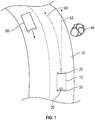
- FIG. 1 schematically illustrates an exemplary vehicle 10 including an advanced driver assistance system (ADAS) 20.
- the ADAS is a dedicated controller including a memory and a processor, with the memory storing instructions for operating the ADAS.
- the ADAS is either a hardware or software component within a large engine controller, and the instructions for operating the ADAS are stored within the larger engine controller.
- the ADAS 20 is integrated with multiple sensors 30 disposed about the vehicle 10, and uses the sensor data to assist in operation of the vehicle 10.
- the sensors 30 can include lane detection systems, cameras, accelerometers, yaw sensors, and any similar type of sensor 30.
- the exemplary ADAS 20 includes one or more internal systems configured to identify the presence of objects, such as a tree 40 or approaching vehicle 50 in front of the vehicle 10. The object detection can be performed using any object detection methodology capable of detecting an object using the available sensors.
- the ADAS 20 In addition to detecting the presence of an object in front of the vehicle 10, the ADAS 20 is tasked with determining whether an estimated path 60, 62 of the vehicle 10 will result in an intersection with the object 40, 50 or not. Based on the determination, the ADAS 20 can recommend or enforce corrective measures to avoid potential collision with the detected object 40, 50. The recommendation or enforcement of corrective measures is collectively referred to as an ADAS 20 action.
- the ADAS 20 can either prompt the driver to turn (recommend a corrective measure) or apply the vehicles brakes (enforce a corrective measure) depending on the distance and speed difference between the vehicle 10 and the detected object 40, 50.
- the ADAS 20 includes methodologies for multiple distinct ways of estimating or predicting the path 60, 62 of the vehicle 10. Included in the multiple ways of estimating the path 60, 62 are methodologies that utilize only the yaw-rate of the vehicle 10, and methodologies that fuse data from one or more inputs from sensors 30 with a yaw-rate to determine the estimated path 60, 62. It is appreciated that other known or conventional path estimation methodologies can be utilized in place of, or alongside, the path estimation methodologies described herein. In such an example the ADAS 20 incorporates further decision matrices to determine which path estimation methodology to use, factoring in the particular strengths and weaknesses of each methodology.
- Each methodology for determining the estimated path 60, 62 has corresponding strengths and weaknesses.
- some yaw-rate only path predictions provide for a faster ADAS 20 response but are less reliable and less stable at mid to long range distances between the vehicle 10 and the object 40, 50 due to sensor accuracy and limits on yaw rate.
- some sensor fused path predictions are more reliable at long range, but provide a slower response to any given driver action due to the consideration of the fused data.
- a sensor fused methodology is any path prediction scheme that estimates a vehicle path 60, 62 based on distinct sensor inputs.
- a lane detection sensor output can be fused with the yaw-rate to estimate a travel path 60, 62 of the vehicle 10.
- the sensor data fused to the yaw-rate data can include radar/LIDAR detection indicating the barrier of the road.
- the fused data can include a combination of the yaw rate and available map data indicating a direction of the road 70 on which the vehicle 10 is traveling, available GPS or other positioning system data indicative of a geographic positioning of the vehicle 10 (collectively referred to as a geographic vehicle location), or step by step direction data of the vehicle 10.
- Figure 2 schematically illustrates an exemplary method 100 by which the ADAS 20 determines which path prediction system, and thus which estimated path 60, 62, to utilize in detecting if a collision is imminent.
- the ADAS 20, or another vehicle system detects an object 40, 50 forward of the vehicle in a "Detect Object" step 110.
- Detect Object refers to an object in the vehicle's general direction of travel, and can include an object in the rear of the vehicle 10 when the vehicle 10 is traveling in reverse.
- the ADAS 20 estimates a distance between the vehicle 10 and the object 40, 50, as well as a rate of approach between the vehicle 10 and the object 40, 50 in an "Estimate Distance Between Vehicle and Object" step 120.
- the ADAS 20 only estimates the distance, and the rate of approach of the vehicle 10 is not considered in the determination process.
- the rate of approach can be approximated using a detected travel speed of the vehicle 10 or estimated based on a combination of the travel speed of the vehicle 10 and additional factors.
- the threshold distance is, in one example, a predetermined distance at which the available response time allows the sensor fused path determination sufficient time to respond and the ADAS 20 to react.
- the specific predetermined distance can be an empirically determined threshold set via laboratory testing and vehicle operation data from open world testing, and is stored within the vehicle 10 ADAS 20 in a look up table.
- the threshold distance can be adjusted further or closer depending on the rate of speed at which the vehicle 10 is traveling. This adjustment allows the ADAS 20 to compensate for a distance covered during an operator's reaction time, as well as the ability of the vehicle 10 to respond to a given object detection scheme.
- the lookup table is more complicated and includes multiple thresholds with each threshold being dependent on other factors such as the travel speed of the vehicle 10.
- the particular threshold, or thresholds, utilized by the ADAS 20 to determine which path estimation methodology to utilize can be determined via a machine learning system trained using an empirical data set.
- the empirical data set includes actual vehicle operation data and can include open world testing, laboratory testing, and/or a combination of the two.
- the ADAS 20 determines that the reliability of the yaw-only path estimation is sufficient and the decreased response time is needed, and the ADAS 20 uses the yaw-only estimated path 62 to determine an appropriate driver assistance response in a "User Yaw-Only Estimation" step 140.
- the driver assistance response in such a case can be warning indicators, automatic breaking, automatic swerving, or other collision avoidance techniques.
- the ADAS 20 determines that the decreased response time is unnecessary and the increased mid to long range reliability is desirable in a "Use Sensor Fused Estimation" step 150.
- the driver assistance response in such a case can include warning indicators, automatic braking, automatic swerving, or any similar corrective action.
- ADAS 20 While the exemplary ADAS 20 described herein includes two methodologies for determining the estimated path 60, 62, it is appreciated that the ADAS 20 can be expanded to include additional methodologies by one of skill in the art. In such an example, threshold windows are utilized to determine which of the multiple path estimation schemes should be utilized in any given situation.
- the ADAS 20 can be a software module 210 stored within a memory 220 of a controller 200 such as a vehicle controller.
- the software module 210 is configured to cause a processor 230 in the controller 200 to perform the method described at Figure 2 .
Landscapes
- Engineering & Computer Science (AREA)
- Physics & Mathematics (AREA)
- Radar, Positioning & Navigation (AREA)
- Remote Sensing (AREA)
- General Physics & Mathematics (AREA)
- Automation & Control Theory (AREA)
- Transportation (AREA)
- Mechanical Engineering (AREA)
- Computer Networks & Wireless Communication (AREA)
- Electromagnetism (AREA)
- Mathematical Physics (AREA)
- Traffic Control Systems (AREA)
- Control Of Driving Devices And Active Controlling Of Vehicle (AREA)
Abstract
Description
- The present disclosure relates generally to computational models for determining if a detected object is in a vehicle path, and more specifically to a computational model configured to adapt the determination between at least two methods for estimating a vehicle path.
- Semi-automated vehicles utilize sensor arrays including video cameras, speed sensors, road sensors and the like to assist a driver in control the operation of the vehicle. Included within this control is the pathing (determining the travel route) of the vehicle, the detection of objects within the path, and determining an appropriate response to the detection of one or more objects that are intersected by the estimated path. The decision process can be further complicated in semi-automated vehicles when the operator alters the path unexpectedly and/or the object may move unexpectedly.
- Driver assistance semi-automated vehicle systems are referred to as advanced driver assistance systems (ADAS) and assist the driver in operating the vehicle. The object detection strategy for ADAS requires sufficiently accurate in-path detection in order to prevent collisions between the vehicle and any detected objects. Some existing ADAS are integrated with one or more vehicle sensors, and the data from the vehicle sensors is utilized to determine the expected path of the vehicle.
- According to one example, a method for operating an advanced driver assistance systems (ADAS) includes determining a distance between an object and a vehicle, selecting a path estimation methodology from a plurality of path estimation methodologies based at least in part on a distance between the vehicle and the object, and activating at least one advanced driver assistance systems ADAS action in response to determining that the object intersects the estimated path.
- In another example of the above method, selecting the path estimation methodology from the plurality of path estimation methodologies comprises comparing the determined distance to a distance threshold and selecting a first path estimation methodology in response to the determined distance being less than or equal to the distance threshold.
- In another example of any of the above methods, the first path estimation methodology is a yaw rate only prediction methodology.
- In another example of any of the above methods, selecting the path estimation methodology from the plurality of path estimation methodologies comprises comparing the determined distance to a distance threshold and selecting a second path estimation methodology in response to the determined distance being greater than the distance threshold.
- In another example of any of the above methods, the second path estimation methodology estimates a vehicle path based on a combination of vehicle yaw rate and at least one of an additional sensor output and a vehicle location.
- In another example of any of the above methods, the at least one of the additional sensor output and the vehicle location is the additional sensor output, and the additional sensor output comprises at least one of an output of a lane detection system, camera, radar/LIDAR, and GPS.
- In another example of any of the above methods, the at least one of the additional sensor output and the vehicle location includes a geographic vehicle location.
- In another example of any of the above methods, selecting the path estimation methodology from the plurality of path estimation methodologies based at least in part on the distance between the vehicle and the object includes selecting the path estimation methodology based at least in part on the distance between the vehicle and the object and on a rate of travel of at least one of the vehicle and the object.
- In another example of any of the above methods, selecting the path estimation methodology from the plurality of path estimation methodologies comprises comparing the determined distance to a distance threshold with the distance threshold being a single threshold.
- In another example of any of the above methods, selecting the path estimation methodology from the plurality of path estimation methodologies comprises comparing the determined distance to a distance threshold with the distance threshold being at least partially dependent upon a rate of speed of the vehicle.
- In another example of any of the above methods, selecting the path estimation methodology from the plurality of path estimation methodologies comprises comparing the determined distance to a distance threshold with the distance threshold being at least partially dependent upon a rate of speed of the vehicle, as well as potentially the angle/rate of steering.
- An exemplary vehicle controller includes a memory, a processor, and at least one input configured to receive sensor outputs from a plurality of sensors including a vehicle yaw sensor, at least one speed sensor and a plurality of cameras, and the memory stores an advanced driver assistance systems (ADAS) including an object detection system and a path estimation system, the ADAS being configured to select a path estimation methodology form a plurality of path estimation methodologies in response to the object detection system detecting an object, wherein the detection is based at least in part on a distance between the vehicle and the detected object.
- In another example of the above vehicle controller, selecting the path estimation methodology from the plurality of path estimation methodologies comprises comparing the distance between the vehicle and the detected object to a distance threshold and selecting a first path estimation methodology in response to the determined distance being less than or equal to the distance threshold.
- In another example of any of the above vehicle controllers, the first path estimation methodology is a yaw rate only prediction methodology.
- In another example of any of the above vehicle controllers, selecting the path estimation methodology from the plurality of path estimation methodologies comprises comparing the distance between the vehicle and the detected object to a distance threshold and selecting a second path estimation methodology in response to the determined distance being greater than the distance threshold.
- In another example of any of the above vehicle controllers, the second path estimation methodology estimates a vehicle path based on a combination of vehicle yaw rate and at least one of an additional sensor output and a vehicle location.
- In another example of any of the above vehicle controllers, the ADAS further comprises an automated response system configured to enforce a corrective action in response to the detected object intersecting with the estimated path and the detected distance being less than a threshold.
- In another example of any of the above vehicle controllers, the ADAS further comprises an automated response system configured to recommend a corrective action in response to the detected object intersecting with the estimated path and the detected distance being greater than a threshold.
- An exemplary non-transitory computer readable medium stores instructions for causing a vehicle controller to determine a distance between an object and a vehicle, select a path estimation methodology from a plurality of path estimation methodologies based at least in part on a distance between the vehicle and the object, and activate at least one ADAS action in response to determining that the object intersects the estimated path.
- In another example of the above computer readable medium, selecting the path estimation methodology from the plurality of path estimation methodologies comprises comparing the determined distance to a distance threshold and selecting a first path estimation methodology in response to the determined distance being less than or equal to the distance threshold.
- These and other features of the present invention can be best understood from the following specification and drawings, the following of which is a brief description.
-
-
Figure 1 illustrates an exemplary vehicle including an object detection system. -
Figure 2 illustrates an exemplary hybrid method for detecting when a target (detected object) is in a vehicle path. -
Figure 3 illustrates an exemplary vehicle controller for implementing the method ofFigure 2 . -
Figure 1 schematically illustrates anexemplary vehicle 10 including an advanced driver assistance system (ADAS) 20. In some examples, the ADAS is a dedicated controller including a memory and a processor, with the memory storing instructions for operating the ADAS. In alternative examples, the ADAS is either a hardware or software component within a large engine controller, and the instructions for operating the ADAS are stored within the larger engine controller. The ADAS 20 is integrated withmultiple sensors 30 disposed about thevehicle 10, and uses the sensor data to assist in operation of thevehicle 10. By way of example thesensors 30 can include lane detection systems, cameras, accelerometers, yaw sensors, and any similar type ofsensor 30. The exemplary ADAS 20 includes one or more internal systems configured to identify the presence of objects, such as atree 40 or approachingvehicle 50 in front of thevehicle 10. The object detection can be performed using any object detection methodology capable of detecting an object using the available sensors. - In addition to detecting the presence of an object in front of the
vehicle 10, the ADAS 20 is tasked with determining whether an estimatedpath vehicle 10 will result in an intersection with theobject object object tree 40, and the ADAS 20 determines that thecurrent path tree 40, and collision is imminent, the ADAS 20 can either prompt the driver to turn (recommend a corrective measure) or apply the vehicles brakes (enforce a corrective measure) depending on the distance and speed difference between thevehicle 10 and the detectedobject - In order to improve the accuracy of the ADAS 20, the ADAS 20 includes methodologies for multiple distinct ways of estimating or predicting the
path vehicle 10. Included in the multiple ways of estimating thepath vehicle 10, and methodologies that fuse data from one or more inputs fromsensors 30 with a yaw-rate to determine the estimatedpath - Each methodology for determining the estimated
path faster ADAS 20 response but are less reliable and less stable at mid to long range distances between thevehicle 10 and theobject vehicle path travel path vehicle 10. In other examples the sensor data fused to the yaw-rate data can include radar/LIDAR detection indicating the barrier of the road.. In another example, the fused data can include a combination of the yaw rate and available map data indicating a direction of theroad 70 on which thevehicle 10 is traveling, available GPS or other positioning system data indicative of a geographic positioning of the vehicle 10 (collectively referred to as a geographic vehicle location), or step by step direction data of thevehicle 10. - With continued reference to
Figure 1 ,Figure 2 schematically illustrates an exemplary method 100 by which theADAS 20 determines which path prediction system, and thus which estimatedpath object step 110. As used herein, "forward of the vehicle" refers to an object in the vehicle's general direction of travel, and can include an object in the rear of thevehicle 10 when thevehicle 10 is traveling in reverse. - Once the
object vehicle 10 and theobject vehicle 10 and theobject step 120. In alternative examples, the ADAS 20 only estimates the distance, and the rate of approach of thevehicle 10 is not considered in the determination process. In systems incorporating the rate of approach, the rate of approach can be approximated using a detected travel speed of thevehicle 10 or estimated based on a combination of the travel speed of thevehicle 10 and additional factors. - Once the distance has been determined, the determined distance is compared to a threshold distance in a "Compare Distance to Threshold"
step 130. The threshold distance is, in one example, a predetermined distance at which the available response time allows the sensor fused path determination sufficient time to respond and theADAS 20 to react. In such examples, the specific predetermined distance can be an empirically determined threshold set via laboratory testing and vehicle operation data from open world testing, and is stored within thevehicle 10ADAS 20 in a look up table. - In alternative examples, such as those where the
estimation step 120 also determines a rate of speed of thevehicle 10, the threshold distance can be adjusted further or closer depending on the rate of speed at which thevehicle 10 is traveling. This adjustment allows theADAS 20 to compensate for a distance covered during an operator's reaction time, as well as the ability of thevehicle 10 to respond to a given object detection scheme. In the alternative examples, the lookup table is more complicated and includes multiple thresholds with each threshold being dependent on other factors such as the travel speed of thevehicle 10. - In yet further examples, the particular threshold, or thresholds, utilized by the
ADAS 20 to determine which path estimation methodology to utilize can be determined via a machine learning system trained using an empirical data set. In such an example the empirical data set includes actual vehicle operation data and can include open world testing, laboratory testing, and/or a combination of the two. - When the comparison to the threshold determines that the distance between the
vehicle 10 and theobject ADAS 20 determines that the reliability of the yaw-only path estimation is sufficient and the decreased response time is needed, and theADAS 20 uses the yaw-only estimatedpath 62 to determine an appropriate driver assistance response in a "User Yaw-Only Estimation"step 140. The driver assistance response in such a case can be warning indicators, automatic breaking, automatic swerving, or other collision avoidance techniques. - When the comparison to the threshold determines that the distance between the
vehicle 10 and theobject ADAS 20 determines that the decreased response time is unnecessary and the increased mid to long range reliability is desirable in a "Use Sensor Fused Estimation"step 150. The driver assistance response in such a case can include warning indicators, automatic braking, automatic swerving, or any similar corrective action. - While the
exemplary ADAS 20 described herein includes two methodologies for determining the estimatedpath ADAS 20 can be expanded to include additional methodologies by one of skill in the art. In such an example, threshold windows are utilized to determine which of the multiple path estimation schemes should be utilized in any given situation. - In some examples, such as the example illustrated in
Figure 3 theADAS 20 can be asoftware module 210 stored within amemory 220 of acontroller 200 such as a vehicle controller. In such examples, thesoftware module 210 is configured to cause aprocessor 230 in thecontroller 200 to perform the method described atFigure 2 . - It is further understood that any of the above described concepts can be used alone or in combination with any or all of the other above described concepts. Although an embodiment of this invention has been disclosed, a worker of ordinary skill in this art would recognize that certain modifications would come within the scope of this invention. For that reason, the following claims should be studied to determine the true scope and content of this invention.
Claims (15)
- A method for operating an advanced driver assistance systems (ADAS) comprising:determining a distance between an object (40, 50) and a vehicle (10);selecting a path estimation methodology from a plurality of path estimation methodologies based at least in part on a distance between the vehicle (10) and the object (40, 50); andactivating at least one advanced driver assistance systems (ADAS) (20) action in response to determining that the object (40, 50) intersects the estimated path (60, 62).
- The method of claim 1, wherein selecting the path estimation methodology from the plurality of path estimation methodologies comprises comparing the determined distance to a distance threshold and selecting a first path estimation methodology in response to the determined distance being less than or equal to the distance threshold and selecting a second path estimation methodology in response to the determined distance being greater than the distance threshold.
- The method of claim 2, wherein the first path estimation methodology is a yaw rate only prediction methodology.
- The method of claim 2, wherein the second path estimation methodology estimates a vehicle path based on a combination of vehicle yaw rate and at least one of an additional sensor output and a vehicle (10) location, and wherein the at least one of the additional sensor output and the vehicle (10) location is the additional sensor output, and the additional sensor output comprises at least one of an output of a lane detection system, camera, radar/LIDAR, and GPS.
- The method of claim 4, wherein the at least one of the additional sensor output and the vehicle (10) location includes a geographic vehicle (10) location.
- The method of any of the preceding claims, wherein selecting the path estimation methodology from the plurality of path estimation methodologies based at least in part on the distance between the vehicle (10) and the object (40, 50) includes selecting the path estimation methodology based at least in part on the distance between the vehicle (10) and the object (40, 50) and on a rate of travel of at least one of the vehicle (10) and the object (40, 50).
- The method of any of the preceding claims, wherein selecting the path estimation methodology from the plurality of path estimation methodologies comprises comparing the determined distance to a distance threshold with the distance threshold being a single threshold.
- The method of any of the preceding claims, wherein selecting the path estimation methodology from the plurality of path estimation methodologies comprises comparing the determined distance to a distance threshold with the distance threshold being at least partially dependent upon a rate of speed of the vehicle (10).
- The method of claim 8, wherein selecting the path estimation methodology from the plurality of path estimation methodologies comprises comparing the determined distance to a distance threshold with the distance threshold being at least partially dependent upon a rate of speed of the vehicle (10), as well as potentially the angle/rate of steering.
- A vehicle controller comprising:a memory (220), a processor (230), and at least one input configured to receive sensor outputs from a plurality of sensors including a vehicle yaw sensor, at least one speed sensor and a plurality of cameras; andthe memory (220) storing an advanced driver assistance systems (ADAS) (20) including an object (40, 50) detection system and a path estimation system, the ADAS (20) being configured to select a path estimation methodology form a plurality of path estimation methodologies in response to the object (40, 50) detection system detecting an object (40, 50), wherein the detection is based at least in part on a distance between the vehicle (10) and the detected object (40, 50).
- The vehicle controller of claim 10, wherein selecting the path estimation methodology from the plurality of path estimation methodologies comprises comparing the distance between the vehicle (10) and the detected object (40, 50) to a distance threshold and selecting a first path estimation methodology in response to the determined distance being less than or equal to the distance threshold and selecting a second path estimation methodology in response to the determined distance being greater than the distance threshold.
- The vehicle controller of claim 11, wherein the first path estimation methodology is a yaw rate only prediction methodology.
- The vehicle controller of claim 11, wherein the second path estimation methodology estimates a vehicle path based on a combination of vehicle yaw rate and at least one of an additional sensor output and a vehicle (10) location.
- The vehicle controller of any of claims 10 - 13, wherein the ADAS (20) further comprises an automated response system configured to enforce a corrective action in response to the detected object (40, 50) intersecting with the estimated path and the detected distance being less than a threshold.
- The vehicle controller of any of claims 10 - 13, wherein the ADAS further comprises an automated response system configured to recommend a corrective action in response to the detected object (40, 50) intersecting with the estimated path and the detected distance being greater than a threshold.
Applications Claiming Priority (1)
| Application Number | Priority Date | Filing Date | Title |
|---|---|---|---|
| US16/712,189 US11400926B2 (en) | 2019-12-12 | 2019-12-12 | Adaptive object in-path detection model for automated or semi-automated vehicle operation |
Publications (1)
| Publication Number | Publication Date |
|---|---|
| EP3835824A1 true EP3835824A1 (en) | 2021-06-16 |
Family
ID=73543102
Family Applications (1)
| Application Number | Title | Priority Date | Filing Date |
|---|---|---|---|
| EP20208886.0A Pending EP3835824A1 (en) | 2019-12-12 | 2020-11-20 | Adaptive object in-path detection model for automated or semi-automated vehicle operation |
Country Status (3)
| Country | Link |
|---|---|
| US (1) | US11400926B2 (en) |
| EP (1) | EP3835824A1 (en) |
| CN (1) | CN112991817B (en) |
Families Citing this family (1)
| Publication number | Priority date | Publication date | Assignee | Title |
|---|---|---|---|---|
| WO2024049539A1 (en) * | 2022-08-30 | 2024-03-07 | University Of Southern California | Coordination of vehicle operation |
Citations (4)
| Publication number | Priority date | Publication date | Assignee | Title |
|---|---|---|---|---|
| JPH07319541A (en) * | 1994-05-20 | 1995-12-08 | Mazda Motor Corp | Vehicle path estimation device |
| US20180052470A1 (en) * | 2016-08-18 | 2018-02-22 | GM Global Technology Operations LLC | Obstacle Avoidance Co-Pilot For Autonomous Vehicles |
| US20180174459A1 (en) * | 2016-12-15 | 2018-06-21 | Hyundai Motor Company | Apparatus and method for generating path of vehicle |
| US20180281814A1 (en) * | 2014-11-06 | 2018-10-04 | Autoliv Development Ab | System and method for vehicle path prediction |
Family Cites Families (7)
| Publication number | Priority date | Publication date | Assignee | Title |
|---|---|---|---|---|
| US6820006B2 (en) * | 2002-07-30 | 2004-11-16 | The Aerospace Corporation | Vehicular trajectory collision conflict prediction method |
| WO2016183074A1 (en) | 2015-05-10 | 2016-11-17 | Mobileye Vision Technologies Ltd. | Road profile along a predicted path |
| US11235777B2 (en) | 2015-10-15 | 2022-02-01 | Harman International Industries, Incorporated | Vehicle path prediction and target classification for autonomous vehicle operation |
| US9704403B2 (en) * | 2015-12-03 | 2017-07-11 | Institute For Information Industry | System and method for collision avoidance for vehicle |
| EP3433131B1 (en) * | 2016-03-23 | 2023-07-12 | Netradyne, Inc. | Advanced path prediction |
| US10077052B2 (en) * | 2016-03-31 | 2018-09-18 | Faraday&Future Inc. | State-based operation for autonomous vehicles |
| JP6547735B2 (en) * | 2016-12-22 | 2019-07-24 | トヨタ自動車株式会社 | Collision avoidance support device |
-
2019
- 2019-12-12 US US16/712,189 patent/US11400926B2/en active Active
-
2020
- 2020-11-20 EP EP20208886.0A patent/EP3835824A1/en active Pending
- 2020-12-11 CN CN202011462213.8A patent/CN112991817B/en active Active
Patent Citations (4)
| Publication number | Priority date | Publication date | Assignee | Title |
|---|---|---|---|---|
| JPH07319541A (en) * | 1994-05-20 | 1995-12-08 | Mazda Motor Corp | Vehicle path estimation device |
| US20180281814A1 (en) * | 2014-11-06 | 2018-10-04 | Autoliv Development Ab | System and method for vehicle path prediction |
| US20180052470A1 (en) * | 2016-08-18 | 2018-02-22 | GM Global Technology Operations LLC | Obstacle Avoidance Co-Pilot For Autonomous Vehicles |
| US20180174459A1 (en) * | 2016-12-15 | 2018-06-21 | Hyundai Motor Company | Apparatus and method for generating path of vehicle |
Also Published As
| Publication number | Publication date |
|---|---|
| CN112991817B (en) | 2024-01-16 |
| US20210179091A1 (en) | 2021-06-17 |
| US11400926B2 (en) | 2022-08-02 |
| CN112991817A (en) | 2021-06-18 |
Similar Documents
| Publication | Publication Date | Title |
|---|---|---|
| CN109649390B (en) | Autonomous car following system and method for automatically driving car | |
| EP3591638B1 (en) | Drive assistance method and drive assistance device | |
| US11498577B2 (en) | Behavior prediction device | |
| CN107719364B (en) | Control system and control method for local motor vehicle | |
| US12036988B2 (en) | Method and control unit for operating an adaptive cruise controller | |
| US11780434B2 (en) | Lane change intention estimation of a vehicle | |
| JP6822752B2 (en) | Driving assistance technology for active vehicle control | |
| US9457809B2 (en) | Collision possibility determination apparatus, drive assist apparatus, collision possibility determination method, and collision possibility determination program | |
| US10444346B2 (en) | Method for migrating radar sensor limitations with video camera input for active braking for pedestrians | |
| US20150239472A1 (en) | Vehicle-installed obstacle detection apparatus having function for judging motion condition of detected object | |
| US11938924B2 (en) | Driving assistance control apparatus for vehicle, driving assistance control system for vehicle, and driving assistance control method for vehicle | |
| KR20190124118A (en) | Apparatus and method for providing safety strategy of vehicle | |
| US20140142839A1 (en) | Driving assistance device and driving assistance method | |
| GB2500426A (en) | Autonomous cruise control | |
| US9862383B2 (en) | Method for operating a vehicle based on one or more setpoint trajectories | |
| US11565700B2 (en) | Vehicle control device and vehicle control method | |
| CN113335311B (en) | Vehicle collision detection method and device, vehicle and storage medium | |
| JP2020040648A (en) | Methods of driving automobiles, especially motorcycles, computer programs | |
| JP2018101295A (en) | Object detection device | |
| EP4071024B1 (en) | A vehicle control system | |
| US10787171B2 (en) | Method for operating a vehicle | |
| GB2576206A (en) | Sensor degradation | |
| CN114919574B (en) | Automatic emergency avoidance system and control method based on the running state of the preceding vehicle | |
| US11400926B2 (en) | Adaptive object in-path detection model for automated or semi-automated vehicle operation | |
| KR20190133522A (en) | Vehicle control device using vehicle condition recognition based on sensor information and V2X information fusion based vehicle situation recognition |
Legal Events
| Date | Code | Title | Description |
|---|---|---|---|
| PUAI | Public reference made under article 153(3) epc to a published international application that has entered the european phase |
Free format text: ORIGINAL CODE: 0009012 |
|
| STAA | Information on the status of an ep patent application or granted ep patent |
Free format text: STATUS: THE APPLICATION HAS BEEN PUBLISHED |
|
| AK | Designated contracting states |
Kind code of ref document: A1 Designated state(s): AL AT BE BG CH CY CZ DE DK EE ES FI FR GB GR HR HU IE IS IT LI LT LU LV MC MK MT NL NO PL PT RO RS SE SI SK SM TR |
|
| STAA | Information on the status of an ep patent application or granted ep patent |
Free format text: STATUS: REQUEST FOR EXAMINATION WAS MADE |
|
| 17P | Request for examination filed |
Effective date: 20211202 |
|
| RBV | Designated contracting states (corrected) |
Designated state(s): AL AT BE BG CH CY CZ DE DK EE ES FI FR GB GR HR HU IE IS IT LI LT LU LV MC MK MT NL NO PL PT RO RS SE SI SK SM TR |
|
| RAP3 | Party data changed (applicant data changed or rights of an application transferred) |
Owner name: APTIV TECHNOLOGIES LIMITED |
|
| STAA | Information on the status of an ep patent application or granted ep patent |
Free format text: STATUS: EXAMINATION IS IN PROGRESS |
|
| RAP1 | Party data changed (applicant data changed or rights of an application transferred) |
Owner name: APTIV TECHNOLOGIES AG |
|
| 17Q | First examination report despatched |
Effective date: 20240415 |
|
| RAP3 | Party data changed (applicant data changed or rights of an application transferred) |
Owner name: APTIV TECHNOLOGIES AG |