EP3835695A1 - Drawer assembly for refrigerator - Google Patents
Drawer assembly for refrigerator Download PDFInfo
- Publication number
- EP3835695A1 EP3835695A1 EP19846105.5A EP19846105A EP3835695A1 EP 3835695 A1 EP3835695 A1 EP 3835695A1 EP 19846105 A EP19846105 A EP 19846105A EP 3835695 A1 EP3835695 A1 EP 3835695A1
- Authority
- EP
- European Patent Office
- Prior art keywords
- sliding
- side wall
- partition plate
- sliding groove
- end wall
- Prior art date
- Legal status (The legal status is an assumption and is not a legal conclusion. Google has not performed a legal analysis and makes no representation as to the accuracy of the status listed.)
- Granted
Links
Images

Classifications
-
- F—MECHANICAL ENGINEERING; LIGHTING; HEATING; WEAPONS; BLASTING
- F25—REFRIGERATION OR COOLING; COMBINED HEATING AND REFRIGERATION SYSTEMS; HEAT PUMP SYSTEMS; MANUFACTURE OR STORAGE OF ICE; LIQUEFACTION SOLIDIFICATION OF GASES
- F25D—REFRIGERATORS; COLD ROOMS; ICE-BOXES; COOLING OR FREEZING APPARATUS NOT OTHERWISE PROVIDED FOR
- F25D25/00—Charging, supporting, and discharging the articles to be cooled
- F25D25/02—Charging, supporting, and discharging the articles to be cooled by shelves
- F25D25/024—Slidable shelves
- F25D25/025—Drawers
-
- A—HUMAN NECESSITIES
- A47—FURNITURE; DOMESTIC ARTICLES OR APPLIANCES; COFFEE MILLS; SPICE MILLS; SUCTION CLEANERS IN GENERAL
- A47B—TABLES; DESKS; OFFICE FURNITURE; CABINETS; DRAWERS; GENERAL DETAILS OF FURNITURE
- A47B57/00—Cabinets, racks or shelf units, characterised by features for adjusting shelves or partitions
- A47B57/58—Cabinets, racks or shelf units, characterised by features for adjusting shelves or partitions with means for adjusting partitions horizontally
-
- A—HUMAN NECESSITIES
- A47—FURNITURE; DOMESTIC ARTICLES OR APPLIANCES; COFFEE MILLS; SPICE MILLS; SUCTION CLEANERS IN GENERAL
- A47B—TABLES; DESKS; OFFICE FURNITURE; CABINETS; DRAWERS; GENERAL DETAILS OF FURNITURE
- A47B57/00—Cabinets, racks or shelf units, characterised by features for adjusting shelves or partitions
- A47B57/58—Cabinets, racks or shelf units, characterised by features for adjusting shelves or partitions with means for adjusting partitions horizontally
- A47B57/583—Cabinets, racks or shelf units, characterised by features for adjusting shelves or partitions with means for adjusting partitions horizontally by sliding
- A47B57/585—Cabinets, racks or shelf units, characterised by features for adjusting shelves or partitions with means for adjusting partitions horizontally by sliding with connection means slidable in a rail
-
- A—HUMAN NECESSITIES
- A47—FURNITURE; DOMESTIC ARTICLES OR APPLIANCES; COFFEE MILLS; SPICE MILLS; SUCTION CLEANERS IN GENERAL
- A47B—TABLES; DESKS; OFFICE FURNITURE; CABINETS; DRAWERS; GENERAL DETAILS OF FURNITURE
- A47B88/00—Drawers for tables, cabinets or like furniture; Guides for drawers
- A47B88/40—Sliding drawers; Slides or guides therefor
- A47B88/473—Braking devices, e.g. linear or rotational dampers or friction brakes; Buffers; End stops
- A47B88/477—Buffers; End stops
-
- A—HUMAN NECESSITIES
- A47—FURNITURE; DOMESTIC ARTICLES OR APPLIANCES; COFFEE MILLS; SPICE MILLS; SUCTION CLEANERS IN GENERAL
- A47B—TABLES; DESKS; OFFICE FURNITURE; CABINETS; DRAWERS; GENERAL DETAILS OF FURNITURE
- A47B88/00—Drawers for tables, cabinets or like furniture; Guides for drawers
- A47B88/90—Constructional details of drawers
- A47B88/969—Drawers having means for organising or sorting the content
- A47B88/975—Drawers having means for organising or sorting the content in the form of repositionable partition walls
-
- A—HUMAN NECESSITIES
- A47—FURNITURE; DOMESTIC ARTICLES OR APPLIANCES; COFFEE MILLS; SPICE MILLS; SUCTION CLEANERS IN GENERAL
- A47B—TABLES; DESKS; OFFICE FURNITURE; CABINETS; DRAWERS; GENERAL DETAILS OF FURNITURE
- A47B2210/00—General construction of drawers, guides and guide devices
- A47B2210/0091—Drawer movement damping
-
- A—HUMAN NECESSITIES
- A47—FURNITURE; DOMESTIC ARTICLES OR APPLIANCES; COFFEE MILLS; SPICE MILLS; SUCTION CLEANERS IN GENERAL
- A47B—TABLES; DESKS; OFFICE FURNITURE; CABINETS; DRAWERS; GENERAL DETAILS OF FURNITURE
- A47B2210/00—General construction of drawers, guides and guide devices
- A47B2210/17—Drawers used in connection with household appliances
- A47B2210/175—Refrigerators or freezers
Definitions
- the present invention relates to the technical field of refrigerator storage devices, and particularly relates to a drawer assembly for a refrigerator.
- a drawer for storage is disposed inside a refrigerator chamber.
- a partition plate is disposed inside the drawer, and the drawer is separated into different spaces by the movement of the partition plate to meet storage requirements.
- the partition plate in the prior art when moved to two sides, the partition plate usually cannot be closely attached to the side wall of the drawer, and there is a larger gap between the partition plate and the side wall of the drawer, so that a certain storage space is occupied.
- One objective of the present invention is to provide a drawer assembly for a refrigerator, which can provide a storage space to the maximum extent.
- Another objective of the present invention is to attach the partition plate of the drawer assembly to the side walls of the drawer body as much as possible.
- the present invention provides a drawer assembly for a refrigerator, including:
- the sliding partition plate mechanism includes:
- the front end wall and the rear end wall are respectively provided with a first sliding groove and a second sliding groove.
- the first sliding groove and the second sliding groove are aligned in the drawing direction of the drawer body and extend along the left-and-right direction of the drawer body, and the two sliding mechanisms are respectively inserted into the first sliding groove and the second sliding groove and form sliding connection.
- one end of the first sliding groove extends to a corner of the front end wall and the first side wall
- the other end of the first sliding groove extends to a corner of the front end wall and the second side wall
- one end of the second sliding groove extends to a corner of the rear end wall and the first side wall
- the other end of the second sliding groove extends to a corner of the rear end wall and the second side wall, so that the partition plate is attached to the first side wall or the second side wall as much as possible.
- each sliding mechanism includes:
- the sliding partition plate mechanism further includes:
- the drawer assembly includes two sets of sliding partition plate mechanisms arranged in parallel.
- the front end wall is provided with two independent third sliding grooves
- the rear end wall is provided with two fourth sliding grooves aligned with the two third sliding grooves
- the aligned third sliding groove and fourth sliding groove form a sliding groove group
- each sliding groove group and each set of the sliding partition plate mechanism form sliding connection.
- the sliding partition plate mechanism further includes: a first limiting block and a second limiting block which are respectively located at two ends of the guide rod and a third limiting block which is located in the middle position of the guide rod, and the first limiting block, the second limiting block and the third limiting block are respectively configured to limit the sliding partition plate mechanism to slide to corresponding positions.
- one side of each of the first limiting block and the second limiting block close to the sliding partition plate mechanism is provided with a shock absorbing ring, and both sides of the third limiting block are provided with shock absorbing rings.
- the middle part of the top end of each of the first side wall and the second side wall on the left and right sides of the drawer body is provided with a recess.
- the recess provides a space for the hand of an operator when the sliding partition plate mechanism slides to the first side wall or the second side wall, that is, the recess is configured to accommodate the hand of the operator, and then, the sliding partition plate mechanism is operated to be attached to the first side wall or the second side wall as much as possible to reduce the gap between the side wall and the partition plate, so that the storage space is maximized when the drawer body does not need to be separated so as to improve the user experience.
- the middle part of the top end of each of the first side wall and the second side wall is provided with the recess, a user can be guided to operate the middle part of the sliding partition plate mechanism.
- the force can be more uniform, and the movement can be smoother, and thereby avoiding tilting caused by unsynchronized movement of the front and rear sides of the sliding partition plate mechanism due to the unbalanced force when the sliding partition plate mechanism is shifted from one end, so as to avoid the resulting gap.
- the sliding partition plate mechanism can be attached to the first side wall or the second side wall as much as possible when sliding to two sides of the drawer body, so as to further reduce the gap between the partition plate and the first side wall or the second side wall of the drawer body.
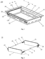
- FIG. 1 is a schematic structural diagram of a drawer assembly according to an embodiment of the present invention.
- the present embodiment provides a drawer assembly 100 for a refrigerator, which includes a drawer body 10 and a sliding partition plate mechanism 20.
- the drawer body 10 includes a bottom wall 11, a front end wall 12 and a rear end wall 13 which are arranged oppositely along a drawing direction D, and a first side wall 14 and a second side wall 15 which are respectively arranged on two sides of the front end wall 12 and the rear end wall 13, and the bottom wall 11, the front end wall 12, the rear end wall 13, the first side wall 14 and the second side wall 15 jointly define an accommodating cavity for holding objects.
- the sliding partition plate mechanism 20 is parallel to the first side wall 14 and located in the accommodating cavity, and the sliding partition plate mechanism 20 is configured to be capable of sliding along the left-and-right direction H of the drawer body 10.
- the middle part of the top end of each of the first side wall 14 and the second side wall 15 is provided with a recess 101 for providing a space when the sliding partition plate mechanism 20 is operated to slide to the first side wall 14 or the second side wall 15, so that the sliding partition plate mechanism 20 is attached to the first side wall 14 or the second side wall 15 as much as possible.
- the middle part of the top end of each of the first side wall 14 and the second side wall 15 on the left and right sides of the drawer body 10 is provided with the recess 101.
- the recess 101 provides a space for the hand of an operator when the sliding partition plate mechanism 20 slides to the first side wall 14 or the second side wall 15, that is, the recess is configured to accommodate the hand of the operator, and then, the sliding partition plate mechanism 20 is operated to be attached to the first side wall 14 or the second side wall 15 as much as possible to reduce the gap between the side wall and the partition plate 21, so that the storage space is maximized when the drawer body 10 does not need to be separated so as to improve the user experience.
- the middle part of the top end of each of the first side wall 14 and the second side wall 15 is provided with the recess 101, a user can be guided to operate the middle part of the sliding partition plate mechanism 20.
- the force can be more uniform, and the movement can be smoother, and thereby avoiding tilting caused by unsynchronized movement of the front and rear sides of the sliding partition plate mechanism 20 due to the unbalanced force when the sliding partition plate mechanism 20 is shifted from one end, so as to avoid the resulting gap.
- FIG. 2 is a schematic structural diagram of a sliding partition plate mechanism of a drawer assembly according to an embodiment of the present invention.
- a sliding partition plate mechanism 20 includes a partition plate 21 and two sliding mechanisms 22.
- the partition plate 21 is parallel to the first side wall 14 and located in the accommodating cavity and is configured to separate the accommodating cavity. Therefore, the shape of the partition plate 21 is basically the same as the cross-sectional size of the drawer body 10.
- the two sliding mechanisms 22 are respectively arranged on two sides of the partition plate 21 and form sliding connection with the front end wall 12 and the rear end wall 13.
- the front end wall 12 and the rear end wall 13 are respectively provided with a first sliding groove 121 and a second sliding groove 131.
- the first sliding groove 121 and the second sliding groove 131 are aligned in the drawing direction D of the drawer body 10 and extend along the left-and-right direction H of the drawer body 10, and the two sliding mechanisms 22 are respectively inserted into the first sliding groove 121 and the second sliding groove 131 and form sliding connection.
- the sliding of the sliding partition plate mechanism 20 relative to the drawer body 10 is completed by the connection form of insertion of the sliding grooves.
- the relative sliding of the two can also be completed by means of sliding rails.
- the first sliding groove 121 and the second sliding groove 131 of the present embodiment can also be used as air vents to play a role of ventilation.
- one end of the first sliding groove 121 extends to a corner of the front end wall 12 and the first side wall 14, the other end of the first sliding groove 121 extends to a corner of the front end wall 12 and the second side wall 15, one end of the second sliding groove 131 extends to a corner of the rear end wall 13 and the first side wall 14, and the other end of the second sliding groove 131 extends to a corner of the rear end wall 13 and the second side wall 15, so that the partition plate 21 is attached to the first side wall 14 or the second side wall 15 as much as possible.
- the sliding partition plate mechanism 20 can be attached to the first side wall 14 or the second side wall 15 as much as possible when sliding to two sides of the drawer body 10, so as to further reduce the gap between the partition plate 21 and the first side wall 14 or the second side wall 15 of the drawer body 10.
- each sliding mechanism 22 includes a sliding base 221 and an insertion piece 222.
- An insertion hole is formed inside the sliding base 221, one end of the insertion piece 222 is inserted into the insertion hole, and the other end passes through the first sliding groove 121 or the second sliding groove 131 to be fixedly connected with the partition plate 21.
- the sliding partition plate mechanism 20 further includes a guide rod 23 which extends along the left-and-right direction of the drawer body 10.
- the guide rod 23 can be fixed to the drawer body 10.
- the sliding base 221 is provided with a connecting hole for penetration of the guide rod 23, so that the sliding base 221 is constrained by the first sliding groove 121 or the second sliding groove 131 and the guide rod 23 simultaneously when moving, and the sliding base 221 slides more smoothly and has better directionality.
- the drawer assembly 100 includes a set of sliding partition plate mechanism 20 which can separate a drawer into two cavities.
- the sliding partition plate mechanism 20 of the drawer assembly 100 shown in figure 1 is located on the side wall of the drawer body 10. When the sliding partition plate mechanism 20 slides to the side wall of the drawer body 10, a larger cavity is formed inside the drawer body 10.
- the drawer assembly 100 includes two sets of sliding partition plate mechanisms 20 arranged in parallel.
- the drawer body 10 can be separated into three independent cavities at most.
- the two sets of sliding partition plate mechanisms 20 can respectively slide to two sides of the drawer body 10, so as to reduce the gap between the partition plate 21 and the side wall as much as possible to maximize the space.
- Figure 5 is a schematic structural diagram of a drawer assembly according to another embodiment of the present invention.
- the front end wall 12 is provided with two independent third sliding grooves 122
- the rear end wall 13 is provided with two fourth sliding grooves 132 aligned with the two third sliding grooves 122
- the aligned third sliding groove 122 and fourth sliding groove 132 form a sliding groove group
- each sliding groove group and each set of the sliding partition plate mechanism 20 form sliding connection.
- each set of the sliding partition plate mechanism 20 slides in the corresponding sliding groove and does not share a sliding groove.
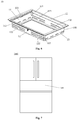
- Figure 6 is a schematic structural diagram of a drawer body of a drawer assembly according to an embodiment of the present invention.
- the left end of the third sliding groove 122 on the left side of the front end wall 12 extends to the corner 102 of the front end wall 12 and the first side wall 14, and the right end of the third sliding groove 122 on the right side of the front end wall 12 extends to the corner 103 of the front end wall 12 and the second side wall 15.
- the left end of the fourth sliding groove 132 on the left side of the rear end wall 13 extends to the corner 104 of the rear end wall 13 and the first side wall 14, and the right end of the fourth sliding groove 132 on the right side of the rear end wall 13 extends to the corner 105 of the rear end wall 13 and the second side wall 15.
- the partition plate 21 on the left side is attached to the first side wall 14 as much as possible when moving to the first side wall 14, and the partition plate 21 on the right side is attached to the second side wall 15 as much as possible when moving to the second side wall 15.
- the sliding partition plate mechanism 20 further includes a first limiting block 24 and a second limiting block 25 which are respectively located at two ends of the guide rod 23 and a third limiting block 26 which is located in the middle position of the guide rod 23, and the first limiting block, the second limiting block and the third limiting block are respectively configured to limit the sliding partition plate mechanism 20 to slide to corresponding positions.
- Figure 4 is an enlarged view of part B in Figure 2 .
- one side of each of the first limiting block 24 and the second limiting block 25 close to the sliding partition plate mechanism 20 is provided with a shock absorbing ring 27, and both sides of the third limiting block 26 are provided with shock absorbing rings.
- the arrangement of the shock absorbing rings 27 can effectively buffer the impact of the sliding base 221 of the sliding partition plate mechanism 20 when sliding to this position.
- the shock absorbing ring 27 can be made of a silicone material.
- FIG. 7 is a schematic position diagram of a drawer assembly according to an embodiment of the present invention in a refrigerator.
- the drawer assembly 100 in the above embodiment may be a drawer assembly in a general refrigerating chamber, or a temperature-variable drawer of a refrigerator.
- the drawer assembly 100 is a temperature-variable drawer in a temperature-variable chamber 200 of a high-end French refrigerator 1000, and the temperature-variable chamber 200 is usually independently arranged between a refrigerating chamber and a freezing chamber of the refrigerator.
Landscapes
- Engineering & Computer Science (AREA)
- Chemical & Material Sciences (AREA)
- Combustion & Propulsion (AREA)
- Physics & Mathematics (AREA)
- Mechanical Engineering (AREA)
- Thermal Sciences (AREA)
- General Engineering & Computer Science (AREA)
- Drawers Of Furniture (AREA)
- Refrigerator Housings (AREA)
Abstract
Description
- The present invention relates to the technical field of refrigerator storage devices, and particularly relates to a drawer assembly for a refrigerator.
- Generally, a drawer for storage is disposed inside a refrigerator chamber. In order to improve the utilization efficiency of the drawer, a partition plate is disposed inside the drawer, and the drawer is separated into different spaces by the movement of the partition plate to meet storage requirements.
- When an object with larger volume needs to be stored, it is necessary to move the partition plate to the side wall of the drawer so as to maximize the space of the drawer.
- However, when the partition plate in the prior art is moved to two sides, the partition plate usually cannot be closely attached to the side wall of the drawer, and there is a larger gap between the partition plate and the side wall of the drawer, so that a certain storage space is occupied.
- One objective of the present invention is to provide a drawer assembly for a refrigerator, which can provide a storage space to the maximum extent.
- Another objective of the present invention is to attach the partition plate of the drawer assembly to the side walls of the drawer body as much as possible.
- Specifically, the present invention provides a drawer assembly for a refrigerator, including:
- a drawer body, including: a bottom wall, a front end wall and a rear end wall which are arranged oppositely along a drawing direction, and a first side wall and a second side wall which are respectively arranged on two sides of the front end wall and the rear end wall, so as to utilize the bottom wall, the front end wall, the rear end wall, the first side wall and the second side wall to jointly define an accommodating cavity for holding objects; and
- a sliding partition plate mechanism, which is configured to be capable of sliding along the left-and-right direction of the drawer body, wherein
- the middle part of the top end of each of the first side wall and the second side wall is provided with a recess for providing a space when the sliding partition plate mechanism is operated to slide to the first side wall or the second side wall, so that the sliding partition plate mechanism is attached to the first side wall or the second side wall as much as possible.
- Optionally, the sliding partition plate mechanism includes:
- a partition plate, which is parallel to the first side wall and located in the accommodating cavity, and configured to separate the accommodating cavity; and
- two sliding mechanisms, which are respectively arranged on two sides of the partition plate and form sliding connection with the front end wall and the rear end wall.
- Optionally, the front end wall and the rear end wall are respectively provided with a first sliding groove and a second sliding groove. The first sliding groove and the second sliding groove are aligned in the drawing direction of the drawer body and extend along the left-and-right direction of the drawer body, and the two sliding mechanisms are respectively inserted into the first sliding groove and the second sliding groove and form sliding connection.
- Optionally, one end of the first sliding groove extends to a corner of the front end wall and the first side wall, the other end of the first sliding groove extends to a corner of the front end wall and the second side wall, one end of the second sliding groove extends to a corner of the rear end wall and the first side wall, and the other end of the second sliding groove extends to a corner of the rear end wall and the second side wall, so that the partition plate is attached to the first side wall or the second side wall as much as possible.
- Optionally, each sliding mechanism includes:
- a sliding base, which is internally provided with an insertion hole; and
- an insertion piece, one end of the insertion piece is inserted into the insertion hole, and the other end of the insertion piece passes through the first sliding groove or the second sliding groove to be fixedly connected with the partition plate.
- Optionally, the sliding partition plate mechanism further includes:
- a guide rod, which extends along the left-and-right direction of the drawer body; and
- the sliding base is provided with a connecting hole for penetration of the guide rod, so that the sliding base is constrained by the first sliding groove or the second sliding groove and the guide rod simultaneously when moving.
- Optionally, the drawer assembly includes two sets of sliding partition plate mechanisms arranged in parallel.
- Optionally, the front end wall is provided with two independent third sliding grooves, the rear end wall is provided with two fourth sliding grooves aligned with the two third sliding grooves, the aligned third sliding groove and fourth sliding groove form a sliding groove group, and each sliding groove group and each set of the sliding partition plate mechanism form sliding connection.
- Optionally, the sliding partition plate mechanism further includes:
a first limiting block and a second limiting block which are respectively located at two ends of the guide rod and a third limiting block which is located in the middle position of the guide rod, and the first limiting block, the second limiting block and the third limiting block are respectively configured to limit the sliding partition plate mechanism to slide to corresponding positions. - Optionally, one side of each of the first limiting block and the second limiting block close to the sliding partition plate mechanism is provided with a shock absorbing ring, and both sides of the third limiting block are provided with shock absorbing rings.
- In the present invention, the middle part of the top end of each of the first side wall and the second side wall on the left and right sides of the drawer body is provided with a recess. The recess provides a space for the hand of an operator when the sliding partition plate mechanism slides to the first side wall or the second side wall, that is, the recess is configured to accommodate the hand of the operator, and then, the sliding partition plate mechanism is operated to be attached to the first side wall or the second side wall as much as possible to reduce the gap between the side wall and the partition plate, so that the storage space is maximized when the drawer body does not need to be separated so as to improve the user experience.
- Further, since the middle part of the top end of each of the first side wall and the second side wall is provided with the recess, a user can be guided to operate the middle part of the sliding partition plate mechanism. By shifting the middle part of the sliding partition plate mechanism, the force can be more uniform, and the movement can be smoother, and thereby avoiding tilting caused by unsynchronized movement of the front and rear sides of the sliding partition plate mechanism due to the unbalanced force when the sliding partition plate mechanism is shifted from one end, so as to avoid the resulting gap.
- Further, since two ends of the first sliding groove and the second sliding groove extend to the corners of the drawer body, the sliding partition plate mechanism can be attached to the first side wall or the second side wall as much as possible when sliding to two sides of the drawer body, so as to further reduce the gap between the partition plate and the first side wall or the second side wall of the drawer body.
- According to the following detailed descriptions of specific embodiments of the present invention in conjunction with the drawings, those skilled in the art will more clearly understand the above and other objectives, advantages and features of the present invention.
- Some specific embodiments of the present invention are described in detail below with reference to the drawings by way of example and not limitation. The same reference numerals in the drawings indicate the same or similar components or parts. Those skilled in the art should understand that these drawings are not necessarily drawn in scale. In the drawings:
-
Figure 1 is a schematic structural diagram of a drawer assembly according to an embodiment of the present invention. -
Figure 2 is a schematic structural diagram of a sliding partition plate mechanism of a drawer assembly according to an embodiment of the present invention. -
Figure 3 is an enlarged view of part A inFigure 2 . -
Figure 4 is an enlarged view of part B inFigure 2 . -
Figure 5 is a schematic structural diagram of a drawer assembly according to another embodiment of the present invention. -
Figure 6 is a schematic structural diagram of a drawer body of a drawer assembly according to an embodiment of the present invention. -
Figure 7 is a schematic position diagram of a drawer assembly according to an embodiment of the present invention in a refrigerator. -
Figure 1 is a schematic structural diagram of a drawer assembly according to an embodiment of the present invention. As shown infigure 1 , the present embodiment provides adrawer assembly 100 for a refrigerator, which includes adrawer body 10 and a slidingpartition plate mechanism 20. Thedrawer body 10 includes abottom wall 11, afront end wall 12 and arear end wall 13 which are arranged oppositely along a drawing direction D, and afirst side wall 14 and asecond side wall 15 which are respectively arranged on two sides of thefront end wall 12 and therear end wall 13, and thebottom wall 11, thefront end wall 12, therear end wall 13, thefirst side wall 14 and thesecond side wall 15 jointly define an accommodating cavity for holding objects. The slidingpartition plate mechanism 20 is parallel to thefirst side wall 14 and located in the accommodating cavity, and the slidingpartition plate mechanism 20 is configured to be capable of sliding along the left-and-right direction H of thedrawer body 10. The middle part of the top end of each of thefirst side wall 14 and thesecond side wall 15 is provided with arecess 101 for providing a space when the slidingpartition plate mechanism 20 is operated to slide to thefirst side wall 14 or thesecond side wall 15, so that the slidingpartition plate mechanism 20 is attached to thefirst side wall 14 or thesecond side wall 15 as much as possible. - In the present embodiment, the middle part of the top end of each of the
first side wall 14 and thesecond side wall 15 on the left and right sides of thedrawer body 10 is provided with therecess 101. Therecess 101 provides a space for the hand of an operator when the slidingpartition plate mechanism 20 slides to thefirst side wall 14 or thesecond side wall 15, that is, the recess is configured to accommodate the hand of the operator, and then, the slidingpartition plate mechanism 20 is operated to be attached to thefirst side wall 14 or thesecond side wall 15 as much as possible to reduce the gap between the side wall and thepartition plate 21, so that the storage space is maximized when thedrawer body 10 does not need to be separated so as to improve the user experience. - Further, since the middle part of the top end of each of the
first side wall 14 and thesecond side wall 15 is provided with therecess 101, a user can be guided to operate the middle part of the slidingpartition plate mechanism 20. By shifting the middle part of the slidingpartition plate mechanism 20, the force can be more uniform, and the movement can be smoother, and thereby avoiding tilting caused by unsynchronized movement of the front and rear sides of the slidingpartition plate mechanism 20 due to the unbalanced force when the slidingpartition plate mechanism 20 is shifted from one end, so as to avoid the resulting gap. -
Figure 2 is a schematic structural diagram of a sliding partition plate mechanism of a drawer assembly according to an embodiment of the present invention. In an embodiment, as shown infigure 2 , a slidingpartition plate mechanism 20 includes apartition plate 21 and twosliding mechanisms 22. As shown infigure 1 , thepartition plate 21 is parallel to thefirst side wall 14 and located in the accommodating cavity and is configured to separate the accommodating cavity. Therefore, the shape of thepartition plate 21 is basically the same as the cross-sectional size of thedrawer body 10. The twosliding mechanisms 22 are respectively arranged on two sides of thepartition plate 21 and form sliding connection with thefront end wall 12 and therear end wall 13. - Optionally, as shown in
figure 1 , thefront end wall 12 and therear end wall 13 are respectively provided with a first slidinggroove 121 and a secondsliding groove 131. The first slidinggroove 121 and the second slidinggroove 131 are aligned in the drawing direction D of thedrawer body 10 and extend along the left-and-right direction H of thedrawer body 10, and the two slidingmechanisms 22 are respectively inserted into the first slidinggroove 121 and the second slidinggroove 131 and form sliding connection. In other words, in the present embodiment, the sliding of the slidingpartition plate mechanism 20 relative to thedrawer body 10 is completed by the connection form of insertion of the sliding grooves. In other embodiments, the relative sliding of the two can also be completed by means of sliding rails. The first slidinggroove 121 and the second slidinggroove 131 of the present embodiment can also be used as air vents to play a role of ventilation. - In another embodiment, one end of the first sliding
groove 121 extends to a corner of thefront end wall 12 and thefirst side wall 14, the other end of the first slidinggroove 121 extends to a corner of thefront end wall 12 and thesecond side wall 15, one end of the second slidinggroove 131 extends to a corner of therear end wall 13 and thefirst side wall 14, and the other end of the second slidinggroove 131 extends to a corner of therear end wall 13 and thesecond side wall 15, so that thepartition plate 21 is attached to thefirst side wall 14 or thesecond side wall 15 as much as possible. - Since two ends of the first sliding
groove 121 and the second slidinggroove 131 extend to the corners of thedrawer body 10, the slidingpartition plate mechanism 20 can be attached to thefirst side wall 14 or thesecond side wall 15 as much as possible when sliding to two sides of thedrawer body 10, so as to further reduce the gap between thepartition plate 21 and thefirst side wall 14 or thesecond side wall 15 of thedrawer body 10. -
Figure 3 is an enlarged view of part A inFigure 2 . As shown infigure 3 , in an embodiment, each slidingmechanism 22 includes a slidingbase 221 and aninsertion piece 222. An insertion hole is formed inside the slidingbase 221, one end of theinsertion piece 222 is inserted into the insertion hole, and the other end passes through the first slidinggroove 121 or the second slidinggroove 131 to be fixedly connected with thepartition plate 21. - In another embodiment, as shown in
figure 2 , the slidingpartition plate mechanism 20 further includes aguide rod 23 which extends along the left-and-right direction of thedrawer body 10. Theguide rod 23 can be fixed to thedrawer body 10. The slidingbase 221 is provided with a connecting hole for penetration of theguide rod 23, so that the slidingbase 221 is constrained by the first slidinggroove 121 or the second slidinggroove 131 and theguide rod 23 simultaneously when moving, and the slidingbase 221 slides more smoothly and has better directionality. - In the above embodiment, the
drawer assembly 100 includes a set of slidingpartition plate mechanism 20 which can separate a drawer into two cavities. As shown infigure 1 , the slidingpartition plate mechanism 20 of thedrawer assembly 100 shown infigure 1 is located on the side wall of thedrawer body 10. When the slidingpartition plate mechanism 20 slides to the side wall of thedrawer body 10, a larger cavity is formed inside thedrawer body 10. - In an embodiment, as shown in
figure 2 , thedrawer assembly 100 includes two sets of slidingpartition plate mechanisms 20 arranged in parallel. In the present embodiment, by the arrangement of the two sets of slidingpartition plate mechanisms 20, thedrawer body 10 can be separated into three independent cavities at most. Preferably, since the first slidinggroove 121 and the second slidinggroove 131 extend to the corners of thedrawer body 10, when thepartition plate 21 is not required to separate the cavity of thedrawer body 10, the two sets of slidingpartition plate mechanisms 20 can respectively slide to two sides of thedrawer body 10, so as to reduce the gap between thepartition plate 21 and the side wall as much as possible to maximize the space. -
Figure 5 is a schematic structural diagram of a drawer assembly according to another embodiment of the present invention. In another embodiment, as shown infigure 5 , thefront end wall 12 is provided with two independent third slidinggrooves 122, therear end wall 13 is provided with two fourth slidinggrooves 132 aligned with the two third slidinggrooves 122, the aligned third slidinggroove 122 and fourth slidinggroove 132 form a sliding groove group, and each sliding groove group and each set of the slidingpartition plate mechanism 20 form sliding connection. In other words, in the present embodiment, each set of the slidingpartition plate mechanism 20 slides in the corresponding sliding groove and does not share a sliding groove. -
Figure 6 is a schematic structural diagram of a drawer body of a drawer assembly according to an embodiment of the present invention. In an embodiment, as shown infigure 6 , the left end of the third slidinggroove 122 on the left side of thefront end wall 12 extends to thecorner 102 of thefront end wall 12 and thefirst side wall 14, and the right end of the third slidinggroove 122 on the right side of thefront end wall 12 extends to thecorner 103 of thefront end wall 12 and thesecond side wall 15. The left end of the fourth slidinggroove 132 on the left side of therear end wall 13 extends to thecorner 104 of therear end wall 13 and thefirst side wall 14, and the right end of the fourth slidinggroove 132 on the right side of therear end wall 13 extends to thecorner 105 of therear end wall 13 and thesecond side wall 15. By the arrangement of the sliding grooves, thepartition plate 21 on the left side is attached to thefirst side wall 14 as much as possible when moving to thefirst side wall 14, and thepartition plate 21 on the right side is attached to thesecond side wall 15 as much as possible when moving to thesecond side wall 15. - In an embodiment, the sliding
partition plate mechanism 20 further includes a first limitingblock 24 and a second limitingblock 25 which are respectively located at two ends of theguide rod 23 and a third limitingblock 26 which is located in the middle position of theguide rod 23, and the first limiting block, the second limiting block and the third limiting block are respectively configured to limit the slidingpartition plate mechanism 20 to slide to corresponding positions. -
Figure 4 is an enlarged view of part B inFigure 2 . In another embodiment, as shown infigure 4 , one side of each of the first limitingblock 24 and the second limitingblock 25 close to the slidingpartition plate mechanism 20 is provided with ashock absorbing ring 27, and both sides of the third limitingblock 26 are provided with shock absorbing rings. The arrangement of theshock absorbing rings 27 can effectively buffer the impact of the slidingbase 221 of the slidingpartition plate mechanism 20 when sliding to this position. Theshock absorbing ring 27 can be made of a silicone material. -
Figure 7 is a schematic position diagram of a drawer assembly according to an embodiment of the present invention in a refrigerator. Thedrawer assembly 100 in the above embodiment may be a drawer assembly in a general refrigerating chamber, or a temperature-variable drawer of a refrigerator. As shown infigure 7 , in an embodiment, thedrawer assembly 100 is a temperature-variable drawer in a temperature-variable chamber 200 of a high-endFrench refrigerator 1000, and the temperature-variable chamber 200 is usually independently arranged between a refrigerating chamber and a freezing chamber of the refrigerator. - Hereto, those skilled in the art should realize that although multiple exemplary embodiments of the present invention have been shown and described in detail herein, without departing from the spirit and scope of the present invention, many other variations or modifications that conform to the principles of the present invention can still be directly determined or deduced from the contents disclosed in the present invention. Therefore, the scope of the present invention should be understood and deemed to cover all such other variations or modifications.
Claims (10)
- A drawer assembly for a refrigerator, comprising:a drawer body, comprising: a bottom wall, a front end wall and a rear end wall arranged oppositely along a drawing direction, and a first side wall and a second side wall respectively arranged on two sides of the front end wall and the rear end wall, so as to utilize the bottom wall, the front end wall, the rear end wall, the first side wall and the second side wall to jointly define an accommodating cavity for holding objects; anda sliding partition plate mechanism, configured to be capable of sliding along the left-and-right direction of the drawer body; whereinthe middle part of the top end of each of the first side wall and the second side wall is provided with a recess for providing a space when the sliding partition plate mechanism is operated to slide to the first side wall or the second side wall.
- The drawer assembly according to claim 1, wherein
the sliding partition plate mechanism comprises:a partition plate, parallel to the first side wall and located in the accommodating cavity, and configured to separate the accommodating cavity; andtwo sliding mechanisms, respectively arranged on two sides of the partition plate and respectively form sliding connection with the front end wall and the rear end wall. - The drawer assembly according to claim 2, wherein
the front end wall and the rear end wall are respectively provided with a first sliding groove and a second sliding groove, the first sliding groove and the second sliding groove are aligned in the drawing direction of the drawer body and extend along the left-and-right direction of the drawer body, and the two sliding mechanisms are respectively inserted into the first sliding groove and the second sliding groove and form sliding connection. - The drawer assembly according to claim 3, wherein
one end of the first sliding groove extends to a corner of the front end wall and the first side wall, the other end of the first sliding groove extends to a corner of the front end wall and the second side wall, one end of the second sliding groove extends to a corner of the rear end wall and the first side wall, and the other end of the second sliding groove extends to a corner of the rear end wall and the second side wall. - The drawer assembly according to claim 3, wherein
each sliding mechanism comprises:a sliding base, internally provided with an insertion hole; andan insertion piece, one end of the insertion piece is inserted into the insertion hole, and the other end of the insertion piece passes through the first sliding groove or the second sliding groove to be fixedly connected with the partition plate. - The drawer assembly according to claim 5, wherein
the sliding partition plate mechanism further comprises:a guide rod, extending along the left-and-right direction of the drawer body; andthe sliding base is provided with a connecting hole for penetration of the guide rod, so that the sliding base is constrained by the first sliding groove and the guide rod simultaneously or is constrained by the second sliding groove and the guide rod simultaneously when moving. - The drawer assembly according to claim 6, comprising
two sets of sliding partition plate mechanisms arranged in parallel. - The drawer assembly according to claim 7, wherein
the front end wall is provided with two independent third sliding grooves, the rear end wall is provided with two fourth sliding grooves aligned with the two third sliding grooves, the aligned third sliding groove and fourth sliding groove form a sliding groove group, and each sliding groove group and each set of the sliding partition plate mechanism form sliding connection. - The drawer assembly according to claim 8, wherein
the sliding partition plate mechanism further comprises:a first limiting block and a second limiting block respectively located at two ends of the guide rod and a third limiting block located in a middle position of the guide rod; andthe first limiting block, the second limiting block, and the third limiting block are respectively configured to limit the sliding partition plate mechanism to slide to respective corresponding positions of the first limiting block, the second limiting block, and the third limiting block. - The drawer assembly according to claim 9, wherein
one side of each of the first limiting block and the second limiting block close to the sliding partition plate mechanism is provided with a shock absorbing ring; and
both sides of the third limiting block are provided with shock absorbing rings.
Applications Claiming Priority (2)
| Application Number | Priority Date | Filing Date | Title |
|---|---|---|---|
| CN201810898291.9A CN110822802B (en) | 2018-08-08 | 2018-08-08 | Drawer assembly for refrigerator |
| PCT/CN2019/099097 WO2020029888A1 (en) | 2018-08-08 | 2019-08-02 | Drawer assembly for refrigerator |
Publications (3)
| Publication Number | Publication Date |
|---|---|
| EP3835695A1 true EP3835695A1 (en) | 2021-06-16 |
| EP3835695A4 EP3835695A4 (en) | 2021-09-08 |
| EP3835695B1 EP3835695B1 (en) | 2022-07-06 |
Family
ID=69413393
Family Applications (1)
| Application Number | Title | Priority Date | Filing Date |
|---|---|---|---|
| EP19846105.5A Active EP3835695B1 (en) | 2018-08-08 | 2019-08-02 | Drawer assembly for refrigerator |
Country Status (6)
| Country | Link |
|---|---|
| US (1) | US20210341217A1 (en) |
| EP (1) | EP3835695B1 (en) |
| CN (1) | CN110822802B (en) |
| AU (1) | AU2019318584B2 (en) |
| MX (1) | MX2021001179A (en) |
| WO (1) | WO2020029888A1 (en) |
Families Citing this family (1)
| Publication number | Priority date | Publication date | Assignee | Title |
|---|---|---|---|---|
| CN208817848U (en) * | 2018-08-08 | 2019-05-03 | 青岛海尔股份有限公司 | A kind of refrigerator drawer component |
Family Cites Families (14)
| Publication number | Priority date | Publication date | Assignee | Title |
|---|---|---|---|---|
| CN2291818Y (en) * | 1997-07-02 | 1998-09-23 | 江惠玲 | Structure improved combined lunch box |
| KR20030023777A (en) * | 2001-09-14 | 2003-03-20 | 주식회사 엘지이아이 | Food storing assembly for refrigerator |
| CN202262637U (en) * | 2011-10-20 | 2012-06-06 | 上海市第一中学 | Cabinet capable of adjusting baffle plate vertically |
| CN202470607U (en) * | 2012-03-02 | 2012-10-03 | 海尔集团公司 | Refrigerator drawer provided with clapboard and electric refrigerator |
| CN102679681A (en) * | 2012-06-08 | 2012-09-19 | 青岛海日高科模型有限公司 | Refrigerator drawer with adjustable space |
| US8960824B2 (en) * | 2013-03-15 | 2015-02-24 | Whirlpool Corporation | Customizable drawer liner for a refrigerator drawer |
| CN203912875U (en) * | 2014-03-19 | 2014-11-05 | 董世起 | Small-sized mammalian is isolator in batches |
| KR101716033B1 (en) * | 2015-06-16 | 2017-03-13 | 엘지전자 주식회사 | A refrigerator and a method controlling the same |
| KR102591765B1 (en) * | 2016-11-30 | 2023-10-23 | 삼성전자주식회사 | Refrigerator |
| CN206410424U (en) * | 2016-12-21 | 2017-08-15 | 合肥华凌股份有限公司 | The drawer appliance and refrigerator of refrigerator |
| CN206891015U (en) * | 2017-05-03 | 2018-01-16 | 合肥美的电冰箱有限公司 | Refrigerator drawer and refrigerator |
| CN107726719A (en) * | 2017-10-18 | 2018-02-23 | 青岛海尔股份有限公司 | A kind of refrigerator drawer and the refrigerator with the refrigerator drawer |
| CN108278806B (en) * | 2017-12-25 | 2020-12-11 | 海尔智家股份有限公司 | Storage device and refrigerator having the same |
| CN108050763B (en) * | 2017-12-30 | 2021-05-04 | 海尔智家股份有限公司 | Refrigerator drawer divider, refrigerator drawer and refrigerator having the same |
-
2018
- 2018-08-08 CN CN201810898291.9A patent/CN110822802B/en active Active
-
2019
- 2019-08-02 MX MX2021001179A patent/MX2021001179A/en unknown
- 2019-08-02 EP EP19846105.5A patent/EP3835695B1/en active Active
- 2019-08-02 WO PCT/CN2019/099097 patent/WO2020029888A1/en not_active Ceased
- 2019-08-02 US US17/266,808 patent/US20210341217A1/en not_active Abandoned
- 2019-08-02 AU AU2019318584A patent/AU2019318584B2/en active Active
Also Published As
| Publication number | Publication date |
|---|---|
| EP3835695A4 (en) | 2021-09-08 |
| MX2021001179A (en) | 2021-07-15 |
| WO2020029888A1 (en) | 2020-02-13 |
| CN110822802A (en) | 2020-02-21 |
| EP3835695B1 (en) | 2022-07-06 |
| AU2019318584B2 (en) | 2022-02-17 |
| CN110822802B (en) | 2020-12-25 |
| AU2019318584A1 (en) | 2021-02-25 |
| US20210341217A1 (en) | 2021-11-04 |
Similar Documents
| Publication | Publication Date | Title |
|---|---|---|
| EP3835697B1 (en) | Refrigerator drawer assembly | |
| AU2019319458B2 (en) | Adjustable refrigerator drawer assembly | |
| JP2006078168A (en) | Double drawer of refrigerator | |
| US20110174012A1 (en) | Refrigerator | |
| CN106766630B (en) | Drawer and refrigerator with same | |
| AU2019318584B2 (en) | Drawer assembly for refrigerator | |
| CN106766629A (en) | A kind of drawer and the refrigerator with the drawer | |
| KR20180013186A (en) | Refrigerator | |
| US20190271499A1 (en) | Refrigerator | |
| CN104344655A (en) | Partition for refrigerator refrigerating chamber, refrigerating chamber and refrigerator | |
| CN109780807A (en) | Refrigeration compartment and refrigerator with it | |
| CN109708411B (en) | Flexible dividing drawer and refrigerator having the same | |
| CN204880946U (en) | Storing box and use refrigerator of this storing box | |
| CN209175714U (en) | A kind of automotive service set placing box | |
| CN222634951U (en) | Drawer assembly and refrigerator | |
| KR20040100494A (en) | Refrigerator | |
| KR20030040842A (en) | Door basket for refrigerator | |
| EP2645030A2 (en) | A cooling device with a movable separator | |
| KR20220048076A (en) | A block type shelf structure for a refrigerator and a refrigerator comprising the same | |
| CN221122733U (en) | Drawer for refrigerator and refrigerator | |
| KR100271583B1 (en) | Door pocket having a sliding pocket of a refrigerator | |
| JP2014202442A (en) | Refrigerator | |
| CN211704023U (en) | Survey and drawing informationization management antimagnetic cabinet | |
| KR102677250B1 (en) | Refrigerator | |
| JP2007082950A (en) | Cabinet |
Legal Events
| Date | Code | Title | Description |
|---|---|---|---|
| STAA | Information on the status of an ep patent application or granted ep patent |
Free format text: STATUS: THE INTERNATIONAL PUBLICATION HAS BEEN MADE |
|
| PUAI | Public reference made under article 153(3) epc to a published international application that has entered the european phase |
Free format text: ORIGINAL CODE: 0009012 |
|
| STAA | Information on the status of an ep patent application or granted ep patent |
Free format text: STATUS: REQUEST FOR EXAMINATION WAS MADE |
|
| 17P | Request for examination filed |
Effective date: 20210305 |
|
| AK | Designated contracting states |
Kind code of ref document: A1 Designated state(s): AL AT BE BG CH CY CZ DE DK EE ES FI FR GB GR HR HU IE IS IT LI LT LU LV MC MK MT NL NO PL PT RO RS SE SI SK SM TR |
|
| STAA | Information on the status of an ep patent application or granted ep patent |
Free format text: STATUS: EXAMINATION IS IN PROGRESS |
|
| A4 | Supplementary search report drawn up and despatched |
Effective date: 20210806 |
|
| RIC1 | Information provided on ipc code assigned before grant |
Ipc: A47B 88/975 20170101ALI20210802BHEP Ipc: F25D 25/02 20060101AFI20210802BHEP |
|
| 17Q | First examination report despatched |
Effective date: 20210811 |
|
| DAV | Request for validation of the european patent (deleted) | ||
| DAX | Request for extension of the european patent (deleted) | ||
| GRAP | Despatch of communication of intention to grant a patent |
Free format text: ORIGINAL CODE: EPIDOSNIGR1 |
|
| STAA | Information on the status of an ep patent application or granted ep patent |
Free format text: STATUS: GRANT OF PATENT IS INTENDED |
|
| RIC1 | Information provided on ipc code assigned before grant |
Ipc: A47B 88/975 20170101ALI20220112BHEP Ipc: F25D 25/02 20060101AFI20220112BHEP |
|
| INTG | Intention to grant announced |
Effective date: 20220214 |
|
| GRAS | Grant fee paid |
Free format text: ORIGINAL CODE: EPIDOSNIGR3 |
|
| GRAA | (expected) grant |
Free format text: ORIGINAL CODE: 0009210 |
|
| STAA | Information on the status of an ep patent application or granted ep patent |
Free format text: STATUS: THE PATENT HAS BEEN GRANTED |
|
| AK | Designated contracting states |
Kind code of ref document: B1 Designated state(s): AL AT BE BG CH CY CZ DE DK EE ES FI FR GB GR HR HU IE IS IT LI LT LU LV MC MK MT NL NO PL PT RO RS SE SI SK SM TR |
|
| REG | Reference to a national code |
Ref country code: AT Ref legal event code: REF Ref document number: 1503119 Country of ref document: AT Kind code of ref document: T Effective date: 20220715 Ref country code: CH Ref legal event code: EP |
|
| REG | Reference to a national code |
Ref country code: DE Ref legal event code: R096 Ref document number: 602019016832 Country of ref document: DE |
|
| REG | Reference to a national code |
Ref country code: IE Ref legal event code: FG4D |
|
| REG | Reference to a national code |
Ref country code: LT Ref legal event code: MG9D |
|
| REG | Reference to a national code |
Ref country code: NL Ref legal event code: MP Effective date: 20220706 |
|
| PG25 | Lapsed in a contracting state [announced via postgrant information from national office to epo] |
Ref country code: SE Free format text: LAPSE BECAUSE OF FAILURE TO SUBMIT A TRANSLATION OF THE DESCRIPTION OR TO PAY THE FEE WITHIN THE PRESCRIBED TIME-LIMIT Effective date: 20220706 Ref country code: RS Free format text: LAPSE BECAUSE OF FAILURE TO SUBMIT A TRANSLATION OF THE DESCRIPTION OR TO PAY THE FEE WITHIN THE PRESCRIBED TIME-LIMIT Effective date: 20220706 Ref country code: PT Free format text: LAPSE BECAUSE OF FAILURE TO SUBMIT A TRANSLATION OF THE DESCRIPTION OR TO PAY THE FEE WITHIN THE PRESCRIBED TIME-LIMIT Effective date: 20221107 Ref country code: NO Free format text: LAPSE BECAUSE OF FAILURE TO SUBMIT A TRANSLATION OF THE DESCRIPTION OR TO PAY THE FEE WITHIN THE PRESCRIBED TIME-LIMIT Effective date: 20221006 Ref country code: NL Free format text: LAPSE BECAUSE OF FAILURE TO SUBMIT A TRANSLATION OF THE DESCRIPTION OR TO PAY THE FEE WITHIN THE PRESCRIBED TIME-LIMIT Effective date: 20220706 Ref country code: LV Free format text: LAPSE BECAUSE OF FAILURE TO SUBMIT A TRANSLATION OF THE DESCRIPTION OR TO PAY THE FEE WITHIN THE PRESCRIBED TIME-LIMIT Effective date: 20220706 Ref country code: LT Free format text: LAPSE BECAUSE OF FAILURE TO SUBMIT A TRANSLATION OF THE DESCRIPTION OR TO PAY THE FEE WITHIN THE PRESCRIBED TIME-LIMIT Effective date: 20220706 Ref country code: FI Free format text: LAPSE BECAUSE OF FAILURE TO SUBMIT A TRANSLATION OF THE DESCRIPTION OR TO PAY THE FEE WITHIN THE PRESCRIBED TIME-LIMIT Effective date: 20220706 Ref country code: ES Free format text: LAPSE BECAUSE OF FAILURE TO SUBMIT A TRANSLATION OF THE DESCRIPTION OR TO PAY THE FEE WITHIN THE PRESCRIBED TIME-LIMIT Effective date: 20220706 |
|
| REG | Reference to a national code |
Ref country code: AT Ref legal event code: MK05 Ref document number: 1503119 Country of ref document: AT Kind code of ref document: T Effective date: 20220706 |
|
| PG25 | Lapsed in a contracting state [announced via postgrant information from national office to epo] |
Ref country code: PL Free format text: LAPSE BECAUSE OF FAILURE TO SUBMIT A TRANSLATION OF THE DESCRIPTION OR TO PAY THE FEE WITHIN THE PRESCRIBED TIME-LIMIT Effective date: 20220706 Ref country code: IS Free format text: LAPSE BECAUSE OF FAILURE TO SUBMIT A TRANSLATION OF THE DESCRIPTION OR TO PAY THE FEE WITHIN THE PRESCRIBED TIME-LIMIT Effective date: 20221106 Ref country code: HR Free format text: LAPSE BECAUSE OF FAILURE TO SUBMIT A TRANSLATION OF THE DESCRIPTION OR TO PAY THE FEE WITHIN THE PRESCRIBED TIME-LIMIT Effective date: 20220706 Ref country code: GR Free format text: LAPSE BECAUSE OF FAILURE TO SUBMIT A TRANSLATION OF THE DESCRIPTION OR TO PAY THE FEE WITHIN THE PRESCRIBED TIME-LIMIT Effective date: 20221007 |
|
| REG | Reference to a national code |
Ref country code: CH Ref legal event code: PL |
|
| REG | Reference to a national code |
Ref country code: DE Ref legal event code: R097 Ref document number: 602019016832 Country of ref document: DE |
|
| PG25 | Lapsed in a contracting state [announced via postgrant information from national office to epo] |
Ref country code: SM Free format text: LAPSE BECAUSE OF FAILURE TO SUBMIT A TRANSLATION OF THE DESCRIPTION OR TO PAY THE FEE WITHIN THE PRESCRIBED TIME-LIMIT Effective date: 20220706 Ref country code: RO Free format text: LAPSE BECAUSE OF FAILURE TO SUBMIT A TRANSLATION OF THE DESCRIPTION OR TO PAY THE FEE WITHIN THE PRESCRIBED TIME-LIMIT Effective date: 20220706 Ref country code: MC Free format text: LAPSE BECAUSE OF FAILURE TO SUBMIT A TRANSLATION OF THE DESCRIPTION OR TO PAY THE FEE WITHIN THE PRESCRIBED TIME-LIMIT Effective date: 20220706 Ref country code: LU Free format text: LAPSE BECAUSE OF NON-PAYMENT OF DUE FEES Effective date: 20220802 Ref country code: LI Free format text: LAPSE BECAUSE OF NON-PAYMENT OF DUE FEES Effective date: 20220831 Ref country code: DK Free format text: LAPSE BECAUSE OF FAILURE TO SUBMIT A TRANSLATION OF THE DESCRIPTION OR TO PAY THE FEE WITHIN THE PRESCRIBED TIME-LIMIT Effective date: 20220706 Ref country code: CZ Free format text: LAPSE BECAUSE OF FAILURE TO SUBMIT A TRANSLATION OF THE DESCRIPTION OR TO PAY THE FEE WITHIN THE PRESCRIBED TIME-LIMIT Effective date: 20220706 Ref country code: CH Free format text: LAPSE BECAUSE OF NON-PAYMENT OF DUE FEES Effective date: 20220831 Ref country code: AT Free format text: LAPSE BECAUSE OF FAILURE TO SUBMIT A TRANSLATION OF THE DESCRIPTION OR TO PAY THE FEE WITHIN THE PRESCRIBED TIME-LIMIT Effective date: 20220706 |
|
| REG | Reference to a national code |
Ref country code: BE Ref legal event code: MM Effective date: 20220831 |
|
| PLBE | No opposition filed within time limit |
Free format text: ORIGINAL CODE: 0009261 |
|
| STAA | Information on the status of an ep patent application or granted ep patent |
Free format text: STATUS: NO OPPOSITION FILED WITHIN TIME LIMIT |
|
| PG25 | Lapsed in a contracting state [announced via postgrant information from national office to epo] |
Ref country code: SK Free format text: LAPSE BECAUSE OF FAILURE TO SUBMIT A TRANSLATION OF THE DESCRIPTION OR TO PAY THE FEE WITHIN THE PRESCRIBED TIME-LIMIT Effective date: 20220706 Ref country code: EE Free format text: LAPSE BECAUSE OF FAILURE TO SUBMIT A TRANSLATION OF THE DESCRIPTION OR TO PAY THE FEE WITHIN THE PRESCRIBED TIME-LIMIT Effective date: 20220706 |
|
| 26N | No opposition filed |
Effective date: 20230411 |
|
| PG25 | Lapsed in a contracting state [announced via postgrant information from national office to epo] |
Ref country code: AL Free format text: LAPSE BECAUSE OF FAILURE TO SUBMIT A TRANSLATION OF THE DESCRIPTION OR TO PAY THE FEE WITHIN THE PRESCRIBED TIME-LIMIT Effective date: 20220706 |
|
| PG25 | Lapsed in a contracting state [announced via postgrant information from national office to epo] |
Ref country code: IE Free format text: LAPSE BECAUSE OF NON-PAYMENT OF DUE FEES Effective date: 20220802 |
|
| PG25 | Lapsed in a contracting state [announced via postgrant information from national office to epo] |
Ref country code: SI Free format text: LAPSE BECAUSE OF FAILURE TO SUBMIT A TRANSLATION OF THE DESCRIPTION OR TO PAY THE FEE WITHIN THE PRESCRIBED TIME-LIMIT Effective date: 20220706 |
|
| PG25 | Lapsed in a contracting state [announced via postgrant information from national office to epo] |
Ref country code: BE Free format text: LAPSE BECAUSE OF NON-PAYMENT OF DUE FEES Effective date: 20220831 |
|
| PG25 | Lapsed in a contracting state [announced via postgrant information from national office to epo] |
Ref country code: IT Free format text: LAPSE BECAUSE OF FAILURE TO SUBMIT A TRANSLATION OF THE DESCRIPTION OR TO PAY THE FEE WITHIN THE PRESCRIBED TIME-LIMIT Effective date: 20220706 |
|
| PG25 | Lapsed in a contracting state [announced via postgrant information from national office to epo] |
Ref country code: MK Free format text: LAPSE BECAUSE OF FAILURE TO SUBMIT A TRANSLATION OF THE DESCRIPTION OR TO PAY THE FEE WITHIN THE PRESCRIBED TIME-LIMIT Effective date: 20220706 Ref country code: CY Free format text: LAPSE BECAUSE OF FAILURE TO SUBMIT A TRANSLATION OF THE DESCRIPTION OR TO PAY THE FEE WITHIN THE PRESCRIBED TIME-LIMIT Effective date: 20220706 |
|
| PG25 | Lapsed in a contracting state [announced via postgrant information from national office to epo] |
Ref country code: HU Free format text: LAPSE BECAUSE OF FAILURE TO SUBMIT A TRANSLATION OF THE DESCRIPTION OR TO PAY THE FEE WITHIN THE PRESCRIBED TIME-LIMIT; INVALID AB INITIO Effective date: 20190802 |
|
| PG25 | Lapsed in a contracting state [announced via postgrant information from national office to epo] |
Ref country code: TR Free format text: LAPSE BECAUSE OF FAILURE TO SUBMIT A TRANSLATION OF THE DESCRIPTION OR TO PAY THE FEE WITHIN THE PRESCRIBED TIME-LIMIT Effective date: 20220706 |
|
| PG25 | Lapsed in a contracting state [announced via postgrant information from national office to epo] |
Ref country code: BG Free format text: LAPSE BECAUSE OF FAILURE TO SUBMIT A TRANSLATION OF THE DESCRIPTION OR TO PAY THE FEE WITHIN THE PRESCRIBED TIME-LIMIT Effective date: 20220706 |
|
| PG25 | Lapsed in a contracting state [announced via postgrant information from national office to epo] |
Ref country code: MT Free format text: LAPSE BECAUSE OF FAILURE TO SUBMIT A TRANSLATION OF THE DESCRIPTION OR TO PAY THE FEE WITHIN THE PRESCRIBED TIME-LIMIT Effective date: 20220706 |
|
| PGFP | Annual fee paid to national office [announced via postgrant information from national office to epo] |
Ref country code: DE Payment date: 20250812 Year of fee payment: 7 |
|
| PGFP | Annual fee paid to national office [announced via postgrant information from national office to epo] |
Ref country code: GB Payment date: 20250826 Year of fee payment: 7 |
|
| PGFP | Annual fee paid to national office [announced via postgrant information from national office to epo] |
Ref country code: FR Payment date: 20250828 Year of fee payment: 7 |