EP3835576A1 - Capacity control valve - Google Patents
Capacity control valve Download PDFInfo
- Publication number
- EP3835576A1 EP3835576A1 EP19847395.1A EP19847395A EP3835576A1 EP 3835576 A1 EP3835576 A1 EP 3835576A1 EP 19847395 A EP19847395 A EP 19847395A EP 3835576 A1 EP3835576 A1 EP 3835576A1
- Authority
- EP
- European Patent Office
- Prior art keywords
- valve
- control
- port
- rod
- pressure
- Prior art date
- Legal status (The legal status is an assumption and is not a legal conclusion. Google has not performed a legal analysis and makes no representation as to the accuracy of the status listed.)
- Granted
Links
Images




Classifications
-
- F—MECHANICAL ENGINEERING; LIGHTING; HEATING; WEAPONS; BLASTING
- F04—POSITIVE - DISPLACEMENT MACHINES FOR LIQUIDS; PUMPS FOR LIQUIDS OR ELASTIC FLUIDS
- F04B—POSITIVE-DISPLACEMENT MACHINES FOR LIQUIDS; PUMPS
- F04B27/00—Multi-cylinder pumps specially adapted for elastic fluids and characterised by number or arrangement of cylinders
- F04B27/08—Multi-cylinder pumps specially adapted for elastic fluids and characterised by number or arrangement of cylinders having cylinders coaxial with, or parallel or inclined to, main shaft axis
- F04B27/14—Control
- F04B27/16—Control of pumps with stationary cylinders
- F04B27/18—Control of pumps with stationary cylinders by varying the relative positions of a swash plate and a cylinder block
- F04B27/1804—Controlled by crankcase pressure
-
- F—MECHANICAL ENGINEERING; LIGHTING; HEATING; WEAPONS; BLASTING
- F16—ENGINEERING ELEMENTS AND UNITS; GENERAL MEASURES FOR PRODUCING AND MAINTAINING EFFECTIVE FUNCTIONING OF MACHINES OR INSTALLATIONS; THERMAL INSULATION IN GENERAL
- F16K—VALVES; TAPS; COCKS; ACTUATING-FLOATS; DEVICES FOR VENTING OR AERATING
- F16K11/00—Multiple-way valves, e.g. mixing valves; Pipe fittings incorporating such valves
- F16K11/10—Multiple-way valves, e.g. mixing valves; Pipe fittings incorporating such valves with two or more closure members not moving as a unit
- F16K11/20—Multiple-way valves, e.g. mixing valves; Pipe fittings incorporating such valves with two or more closure members not moving as a unit operated by separate actuating members
- F16K11/24—Multiple-way valves, e.g. mixing valves; Pipe fittings incorporating such valves with two or more closure members not moving as a unit operated by separate actuating members with an electromagnetically-operated valve, e.g. for washing machines
-
- F—MECHANICAL ENGINEERING; LIGHTING; HEATING; WEAPONS; BLASTING
- F16—ENGINEERING ELEMENTS AND UNITS; GENERAL MEASURES FOR PRODUCING AND MAINTAINING EFFECTIVE FUNCTIONING OF MACHINES OR INSTALLATIONS; THERMAL INSULATION IN GENERAL
- F16K—VALVES; TAPS; COCKS; ACTUATING-FLOATS; DEVICES FOR VENTING OR AERATING
- F16K11/00—Multiple-way valves, e.g. mixing valves; Pipe fittings incorporating such valves
- F16K11/10—Multiple-way valves, e.g. mixing valves; Pipe fittings incorporating such valves with two or more closure members not moving as a unit
- F16K11/20—Multiple-way valves, e.g. mixing valves; Pipe fittings incorporating such valves with two or more closure members not moving as a unit operated by separate actuating members
- F16K11/22—Multiple-way valves, e.g. mixing valves; Pipe fittings incorporating such valves with two or more closure members not moving as a unit operated by separate actuating members with an actuating member for each valve, e.g. interconnected to form multiple-way valves
-
- F—MECHANICAL ENGINEERING; LIGHTING; HEATING; WEAPONS; BLASTING
- F04—POSITIVE - DISPLACEMENT MACHINES FOR LIQUIDS; PUMPS FOR LIQUIDS OR ELASTIC FLUIDS
- F04B—POSITIVE-DISPLACEMENT MACHINES FOR LIQUIDS; PUMPS
- F04B27/00—Multi-cylinder pumps specially adapted for elastic fluids and characterised by number or arrangement of cylinders
- F04B27/08—Multi-cylinder pumps specially adapted for elastic fluids and characterised by number or arrangement of cylinders having cylinders coaxial with, or parallel or inclined to, main shaft axis
- F04B27/14—Control
- F04B27/16—Control of pumps with stationary cylinders
- F04B27/18—Control of pumps with stationary cylinders by varying the relative positions of a swash plate and a cylinder block
- F04B27/1804—Controlled by crankcase pressure
- F04B2027/1809—Controlled pressure
- F04B2027/1813—Crankcase pressure
-
- F—MECHANICAL ENGINEERING; LIGHTING; HEATING; WEAPONS; BLASTING
- F04—POSITIVE - DISPLACEMENT MACHINES FOR LIQUIDS; PUMPS FOR LIQUIDS OR ELASTIC FLUIDS
- F04B—POSITIVE-DISPLACEMENT MACHINES FOR LIQUIDS; PUMPS
- F04B27/00—Multi-cylinder pumps specially adapted for elastic fluids and characterised by number or arrangement of cylinders
- F04B27/08—Multi-cylinder pumps specially adapted for elastic fluids and characterised by number or arrangement of cylinders having cylinders coaxial with, or parallel or inclined to, main shaft axis
- F04B27/14—Control
- F04B27/16—Control of pumps with stationary cylinders
- F04B27/18—Control of pumps with stationary cylinders by varying the relative positions of a swash plate and a cylinder block
- F04B27/1804—Controlled by crankcase pressure
- F04B2027/1822—Valve-controlled fluid connection
- F04B2027/1827—Valve-controlled fluid connection between crankcase and discharge chamber
-
- F—MECHANICAL ENGINEERING; LIGHTING; HEATING; WEAPONS; BLASTING
- F04—POSITIVE - DISPLACEMENT MACHINES FOR LIQUIDS; PUMPS FOR LIQUIDS OR ELASTIC FLUIDS
- F04B—POSITIVE-DISPLACEMENT MACHINES FOR LIQUIDS; PUMPS
- F04B27/00—Multi-cylinder pumps specially adapted for elastic fluids and characterised by number or arrangement of cylinders
- F04B27/08—Multi-cylinder pumps specially adapted for elastic fluids and characterised by number or arrangement of cylinders having cylinders coaxial with, or parallel or inclined to, main shaft axis
- F04B27/14—Control
- F04B27/16—Control of pumps with stationary cylinders
- F04B27/18—Control of pumps with stationary cylinders by varying the relative positions of a swash plate and a cylinder block
- F04B27/1804—Controlled by crankcase pressure
- F04B2027/1822—Valve-controlled fluid connection
- F04B2027/1831—Valve-controlled fluid connection between crankcase and suction chamber
-
- F—MECHANICAL ENGINEERING; LIGHTING; HEATING; WEAPONS; BLASTING
- F04—POSITIVE - DISPLACEMENT MACHINES FOR LIQUIDS; PUMPS FOR LIQUIDS OR ELASTIC FLUIDS
- F04B—POSITIVE-DISPLACEMENT MACHINES FOR LIQUIDS; PUMPS
- F04B27/00—Multi-cylinder pumps specially adapted for elastic fluids and characterised by number or arrangement of cylinders
- F04B27/08—Multi-cylinder pumps specially adapted for elastic fluids and characterised by number or arrangement of cylinders having cylinders coaxial with, or parallel or inclined to, main shaft axis
- F04B27/14—Control
- F04B27/16—Control of pumps with stationary cylinders
- F04B27/18—Control of pumps with stationary cylinders by varying the relative positions of a swash plate and a cylinder block
Definitions
- the present invention relates to a capacity control valve configured to variably control a working fluid capacity, and for example, relates to a capacity control valve configured to control, according to a pressure, a discharge amount of a variable displacement compressor used for an air-conditioning system of an automobile.
- a variable displacement compressor used for, e.g., an air-conditioning system of an automobile includes, for example, a rotary shaft to be rotatably driven by an engine, a swash plate coupled such that an inclination angle thereof with respect to the rotary shaft is variable, and a compression piston coupled to the swash plate.
- the inclination angle of the swash plate is changed, and accordingly, a stroke amount of the piston is changed. In this manner, a fluid discharge amount is controlled.
- variable displacement compressor can control the internal pressure of a control chamber as necessary to continuously change the inclination angle of the swash plate while utilizing a suction pressure Ps of a suction chamber for sucking fluid, a discharge pressure Pd of a discharge chamber for discharging fluid pressurized by the piston, and a control pressure Pc of the control chamber housing the swash plate (see Patent Citations 1, 2, and 3).
- continuous drive (hereinafter sometimes merely referred to as "in continuous drive") of the variable displacement compressor
- energization of the capacity control valve is controlled by a control computer, and the capacity control valve moves a valve body in an axial direction by electromagnetic force generated by a solenoid to perform the normal control of opening/closing a main valve to adjust the control pressure Pc of the control chamber of the variable displacement compressor.
- a capacity control valve of Patent Citation 1 is configured such that a control chamber is connected to a discharge chamber through a stationary orifice, and controls a CS valve as a main valve to adjust the pressure of the control chamber with a suction pressure.
- a capacity control valve of Patent Citation 2 is configured such that a control chamber is connected to a suction chamber through a stationary orifice, and controls a DC valve as a main valve to adjust the pressure of the control chamber with a discharge pressure.
- a capacity control valve of Patent Citation 3 controls a CS valve and a DC valve to adjust the pressure of a control chamber.
- the pressure of the control chamber in the variable displacement compressor is controlled as necessary, and the inclination angle of the swash plate with respect to the rotary shaft is continuously changed.
- the stroke amount of the piston is changed such that the fluid discharge amount for the discharge chamber is controlled, and the air-conditioning system is adjusted to have a desired cooling capacity.
- the main valve of the capacity control valve is closed such that the pressure of the control chamber decreases, and in this manner, the inclination angle of the swash plate becomes maximum.
- the capacity control valve can be configured with a simple configuration.
- the stationary orifice connected to the control chamber of the variable displacement compressor has a constant flow path sectional area.
- the CS valve and the DC valve are arranged to enhance controllability.
- Patent Citation 3 fails to describe cooperation of the CS valve and the DC valve, and a favorable control efficiency in normal control cannot be always provided.
- the present invention has been made in view of these problems, and is intended to provide a capacity control valve with a favorable control efficiency in normal control.
- a capacity control valve for controlling a flow rate by energization of a solenoid, including: a valve housing formed with a discharge port through which discharge fluid with a discharge pressure passes, a suction port through which suction fluid with a suction pressure passes, and first and second control ports through which control fluid with a control pressure passes; a rod arranged in the valve housing and driven by the solenoid; a CS valve configured to control a fluid flow between the first control port and the suction port in accordance with a movement of the rod; and a DC valve configured to control a fluid flow between the second control port and the discharge port in accordance with the movement of the rod, wherein in a non-energization state of the solenoid, the CS valve is closed and the DC valve is opened, wherein as the energization of the solenoid becomes larger, the CS valve transitions from a closed state to an open state, and the DC
- the flow rate is controlled by cooperation of the CS valve and the DC valve, and therefore, the control pressure can be controlled with a favorable efficiency.
- the CS valve and the DC valve transition in opposite directions in a low energization current range, only a CS valve opening degree increases in an intermediate current range, and the CS valve and the DC valve transition in the same direction in a high current range.
- the control pressure is controlled based on a difference between the amount of adjustment of the control pressure by the CS valve and the amount of adjustment of the control pressure by the DC valve.
- the control pressure can be finely controlled in association with a current value. Particularly, as energization current increases, the control pressure can be more finely controlled in association with the current value.
- a state in which the DC valve is throttled in the energization of the solenoid is a closed state.
- a control range according to the energization current for the solenoid is broader in the CS valve than in the DC valve. That is, the CS valve is main, and the DC valve is auxiliary. Thus, a favorable control efficiency is provided.
- the DC valve has a spool valve structure, and includes a land portion of the rod and a DC valve seat provided at the inner periphery of the valve housing. According to this preferable configuration, the DC valve can be simply configured.
- the rod is arranged at the inner periphery of the valve housing to partition the suction port and the discharge port. According to this preferable configuration, the capacity control valve can be simply configured.
- the CS valve includes a pressure-sensitive body and a Cs valve seat, the pressure-sensitive body being arranged in a pressure-sensitive chamber formed with the first control port and configured to bias the rod, the CS valve seat being provided at the valve housing. According to this preferable configuration, a structure in which reactive force provided to the rod according to the suction pressure is increased/decreased is made, and controllability of the control pressure is enhanced.
- a spring configured to provide biasing force in an axial direction is arranged between the pressure-sensitive body and the rod. According to this preferable configuration, the spring can deformably move in the axial direction. Thus, even if an axial deformable amount of the pressure-sensitive body is small, the DC valve can be reliably operated.
- the discharge port, the second control port, the suction port, and the first control port or the second control port, the discharge port, the suction port, and the first control port are arranged in description order from a side of the solenoid. According to this preferable configuration, the valve housing can be simply configured.
- a capacity control valve is a capacity control valve for controlling a flow rate by energization of a solenoid, including: a valve housing formed with a discharge port through which discharge fluid with a discharge pressure passes, a suction port through which suction fluid with a suction pressure passes, and first and second control ports through which control fluid with a control pressure passes; a rod arranged in the valve housing, driven by the solenoid, the rod forming a spool valve structure of a DC valve configured to control a fluid flow between the second control port and the discharge port by a land portion arranged at an outer periphery; and a pressure-sensitive body forming a CS valve configured to control a fluid flow between the first control port and the suction port in accordance with a movement of the rod.
- the flow rate is controlled by cooperation of the CS valve and the DC valve, and therefore, the control pressure can be controlled with a favorable efficiency.
- a capacity control valve according to an embodiment will be described with reference to FIGS. 1 to 8 .
- right and left sides as viewed from a front side of FIG. 2 will be described as right and left sides of the capacity control valve.
- the capacity control valve V of the present invention is incorporated into a variable displacement compressor M used for, e.g., an air-conditioning system of an automobile.
- the capacity control valve V variably controls the pressure of working fluid (hereinafter merely referred to as "fluid") as refrigerant, thereby controlling a discharge amount of the variable displacement compressor M and adjusting the air-conditioning system to have a desired cooling capacity.
- variable displacement compressor M As illustrated in FIG. 1 , the variable displacement compressor M has a casing 1 including a discharge chamber 2, a suction chamber 3, a control chamber 4, and multiple cylinders 4a.
- variable displacement compressor M includes a rotary shaft 5 to be rotatably driven by a not-shown engine placed outside the casing 1, a swash plate 6 coupled in an eccentric state with respect to the rotary shaft 5 by a hinge mechanism 8 in the control chamber 4, and multiple pistons 7 coupled to the swash plate 6 and each reciprocatably fitted in the cylinders 4a.
- variable displacement compressor M controls the internal pressure of the control chamber 4 as necessary to continuously change an inclination angle of the swash plate 6 while utilizing a suction pressure Ps of the suction chamber 3 for sucking the fluid, a discharge pressure Pd of the discharge chamber 2 for discharging the fluid pressurized by the piston 7, and a control pressure Pc of the control chamber 4 housing the swash plate 6.
- the variable displacement compressor M changes a stroke amount of the piston 7 to control the fluid discharge amount. Note that for the sake of convenience in description, the capacity control valve V incorporated into the variable displacement compressor M is not shown in FIG. 1 .
- the swash plate 6 is brought into a state in which the swash plate 6 is substantially perpendicular to the rotary shaft 5, i.e., a state in which the swash plate 6 is slightly inclined with respect to a direction perpendicular to the rotary shaft 5. In this state, the stroke amount of the piston 7 is minimum, and pressurization of the fluid in the cylinder 4a by the piston 7 is minimum.
- the amount of fluid discharged to the discharge chamber 2 decreases, and the cooling capacity of the air-conditioning system becomes minimum.
- the control pressure Pc in the control chamber 4 decreases, the inclination angle of the swash plate 6 with respect to the rotary shaft 5 increases and the stroke amount of the piston 7 increases.
- the stroke amount of the piston 7 is maximum, and pressurization of the fluid in the cylinder 4a by the piston 7 is maximum. Accordingly, the amount of fluid discharged to the discharge chamber 2 increases, and the cooling capacity of the air-conditioning system becomes maximum.
- the capacity control valve V incorporated into the variable displacement compressor M adjusts current energizing a coil 86 forming a solenoid 80, controls opening/closing of a CS valve 50 and a DC valve 53 in the capacity control valve V, and controls the fluid flowing into the control chamber 4 or flowing out of the control chamber 4.
- the capacity control valve V variably controls the control pressure Pc in the control chamber 4. Note that upon normal control of the capacity control valve V, the discharge pressure Pd is a higher pressure than the control pressure Pc, and the control pressure Pc is a high pressure of equal to or higher than the suction pressure Ps.
- the CS valve 50 includes an adaptor 70 forming a pressure-sensitive body 61, and a CS valve seat 10a formed at an inner peripheral surface of a first valve housing 10 as a valve housing.
- the DC valve 53 has a spool valve structure, and includes a rod 51 and a DC valve seat 11a formed at an inner peripheral surface of a second valve housing 11 as the valve housing.
- a first land portion 51a as a land portion of the rod 51 contacts or separates from the DC valve seat 11a, and in this manner, the DC valve 53 is opened/closed.
- the capacity control valve V mainly includes the first valve housing 10 and the second valve housing 11 made of a metal material or a resin material, the rod 51 arranged reciprocatably in the axial direction inside the first valve housing 10 and the second valve housing 11, the pressure-sensitive body 61 configured to provide rightward biasing force in the axial direction to the rod 51 according to the suction pressure Ps in a first valve chamber 20, and the solenoid 80 connected to the second valve housing 11 and providing drive force to the rod 51.
- the solenoid 80 mainly includes a casing 81 having an opening 81a opening leftward in the axial direction, a substantially cylindrical stationary iron core 82 inserted into the opening 81a of the casing 81 from the left in the axial direction and fixed to an inner diameter side of the casing 81, the rod 51 inserted into the stationary iron core 82 and arranged reciprocatably in the axial direction, a movable iron core 84 fixed to a right end portion of the rod 51 in the axial direction, a coil spring 85 provided between the stationary iron core 82 and the movable iron core 84 and biasing the movable iron core 84 rightward in the axial direction, and the excitation coil 86 wound around the outside of the stationary iron core 82 through a bobbin.
- a recessed portion 81b recessed rightward in the axial direction on the inner diameter side at a left end in the axial direction is formed.
- a right end portion of the second valve housing 11 in the axial direction is substantially hermetically inserted/fixed into the recessed portion 81b.
- the stationary iron core 82 is made of a rigid body as a magnetic material such as iron or silicon steel, and includes a cylindrical portion 82b extending in the axial direction and formed with an insertion hole 82c into which a right portion of the rod 51 in the axial direction is inserted and an annular flange portion 82d extending in an outer diameter direction from an outer peripheral surface of a left end portion of the cylindrical portion 82b in the axial direction. On the left side in the axial direction with respect to the flange portion 82d, an annular recessed portion 82e recessed in an inner diameter direction from an outer peripheral surface of the cylindrical portion 82b is formed. Note that an O-ring 83 is attached to the annular recessed portion 82e, and therefore, the stationary iron core 82 and the second valve housing 11 are connected and fixed to each other in a hermetic state.
- the stationary iron core 82 is inserted/fixed into a recessed portion 11c recessed leftward in the axial direction on the inner diameter side at a right end, which is inserted/fixed into the recessed portion 81b of the casing 81, of the second valve housing 11 in the axial direction.
- annular space S is formed between a left end surface of the flange portion 82d of the stationary iron core 82 in the axial direction and the recessed portion 11c of the second valve housing 11. Note that the space S is communicated with the insertion hole 82c inside the stationary iron core 82 through a through-hole 82a extending in a radial direction between the flange portion 82d and the annular recessed portion 82e at the cylindrical portion 82b of the stationary iron core 82.
- a Ps port 13 as a suction port communicated with the suction chamber 3 of the variable displacement compressor M and a first Pc port 14 as a first control port communicated with the control chamber 4 of the variable displacement compressor M are formed at the first valve housing 10.
- a second Pc port 15 as a second control port communicated with the control chamber 4 of the variable displacement compressor M and a Pd port 16 as a discharge port communicated with the discharge chamber 2 of the variable displacement compressor M are formed at the second valve housing 11. Note that these ports are, from a solenoid 80 side, formed in the order of the Pd port 16, the second Pc port 15, the Ps port 13, and the first Pc port 14.
- an outer diameter portion at a right end of the first valve housing 10 in the axial direction is recessed leftward in the axial direction to form a step portion 10b, and a left end portion of the second valve housing 11 in the axial direction is fitted onto such an outer diameter portion from the right in the axial direction such that the first valve housing 10 is connected and fixed in a hermetic state.
- a partition adjustment member 12 is substantially hermetically press-fitted in a left end portion of the first valve housing 10 in the axial direction, and therefore, the first valve housing 10 is in a substantially cylindrical shape with a bottom. Note that the partition adjustment member 12 adjusts an installation position of the first valve housing 10 in the axial direction so that the biasing force of the pressure-sensitive body 61 can be adjusted.
- the rod 51 is arranged reciprocatably in the axial direction in the first valve housing 10 and the second valve housing 11, and at part of the inner peripheral surface of the second valve housing 11, a small-diameter guide surface 11b is formed so that an outer peripheral surface of a second land portion 51b (see FIGS. 3 to 6 ) of the rod 51 can slidably contact the guide surface 11b in a substantially hermetic state.
- the first valve chamber 20 which is communicated with the Ps port 13 and in which a left end portion of the rod 51 in the axial direction is arranged and a pressure-sensitive chamber 60 which is communicated with the first Pc port 14 and in which the pressure-sensitive body 61 is arranged are formed.
- a second valve chamber 30 which is communicated with the second Pc port 15 and in which the second land portion 51b (see FIGS. 3 to 6 ) of the rod 51 is arranged and a third valve chamber 40 which is communicated with the Pd port 16, in which the first land portion 51a of the rod 51 is arranged, and which is arranged on the solenoid 80 side of the second valve housing 11 are formed.
- the first valve chamber 20 is defined by an outer peripheral surface at a left end portion of the rod 51 in the axial direction, an inner peripheral surface on the right side in the axial direction with respect to the CS valve seat 10a of the first valve housing 10, and an inner surface of a recessed portion 11d recessed rightward in the axial direction on the inner diameter side at a left end of the second valve housing 11 in the axial direction. Further, in a state in which the first valve housing 10 and the second valve housing 11 are connected and fixed to each other, the first valve chamber 20 and the second valve chamber 30 are partitioned by the second land portion 51b of the rod 51.
- the second valve chamber 30 and the third valve chamber 40 are defined by an outer peripheral surface on the right side in the axial direction with respect to the second land portion 51b of the rod 51 and the inner peripheral surface of the second valve housing 11.
- a through-hole 11e extending in the axial direction from the recessed portion 11c on the right side in the axial direction to the recessed portion 11d on the left side in the axial direction is formed at the second valve housing 11, and the first valve chamber 20 and the space S are communicated with each other through the through-hole 11e.
- the suction pressure Ps of the suction chamber 3 is introduced into the right side in the axial direction as the back side of the movable iron core 84 forming the solenoid 80 through the Ps port 13, the first valve chamber 20, the through-hole 11e of the second valve housing 11, the space S, and the through-hole 82a and the insertion hole 82c of the stationary iron core 82, and accordingly, pressure on both sides of the rod 51 in the axial direction is balanced.
- the pressure-sensitive body 61 mainly includes a bellows core 62 having a built-in coil spring 63, and the adaptor 70 provided at a right end of the bellows core 62 in the axial direction. A left end of the bellows core 62 in the axial direction is fixed to the partition adjustment member 12.
- the pressure-sensitive body 61 is arranged in the pressure-sensitive chamber 60, and by the biasing force of moving the adaptor 70 rightward in the axial direction by the coil spring 63 and the bellows core 62, the tapered end portion 70a of the adaptor 70 sits on the CS valve seat 10a of the first valve housing 10.
- the rod 51 mainly includes a large-diameter portion 51c fixed to the movable iron core 84 (see FIG. 2 ) at a right end portion in the axial direction, a first small-diameter portion 51d formed with a smaller diameter than that of the large-diameter portion 51c on the left side of the large-diameter portion 51c in the axial direction, and a second small-diameter portion 51e formed with a smaller diameter than that of the first small-diameter portion 51d on the left side of the first small-diameter portion 51d in the axial direction.
- the circular ring-shaped first land portion 51a and the circular ring-shaped second land portion 51b extending in the outer diameter direction are formed.
- a portion between the first land portion 51a and the second land portion 51b in the axial direction is in a shape recessed in an annular shape in the inner diameter direction, and a portion on the left side in the axial direction with respect to the second land portion 51b is in a shape with a small diameter.
- the first land portion 51a is in a trapezoidal shape as viewed in the section such that a side portion extending in the inner diameter direction from the left side of an outer peripheral portion 51h in the axial direction is perpendicular to the axial direction of the rod 51 and a side portion extending in the inner diameter direction from the right side of the outer peripheral portion 51h in the axial direction is formed in a tapered shape with respect to the axial direction of the rod 51.
- the length of the outer peripheral portion 51h in the axial direction is set substantially equal to the length of the DC valve seat 11a in the axial direction, the DC valve seat 11a being forming at the inner peripheral surface of the second valve housing 11.
- a left end 51f of the rod 51 in the axial direction i.e., the left end 51f of the second small-diameter portion 51e in the axial direction, is separated from a bottom surface of a recessed portion 70b recessed leftward in the axial direction on the inner diameter side at a right end of the adaptor 70 in the axial direction.
- a coil spring 54 as a spring is fitted onto a left end portion of the second small-diameter portion 51e in the axial direction.
- a left end of the coil spring 54 in the axial direction contacts the bottom surface of the recessed portion 70b of the adaptor 70, and a right end of the coil spring 54 in the axial direction contacts a side portion 51g of the second land portion 51b of the rod 51 on the left side in the axial direction.
- the tapered end portion 70a of the adaptor 70 sits on the CS valve seat 10a of the first valve housing 10, the CS valve 50 is closed (e.g., fully closed), the first land portion 51a of the rod 51 is separated rightward in the axial direction from the DC valve seat 11a of the second valve housing 11, and the DC valve 53 is opened. Moreover, in this state, the degree of elongation of the coil spring 54 is maximum.
- the CS valve 50 is closed (e.g., fully closed), and the DC valve 53 is opened.
- the opening area of the DC valve 53 i.e., the degree of opening of the DC valve 53, is maximum (see FIGS. 7 and 8 ).
- the tapered end portion 70a of the adaptor 70 is separated from the CS valve seat 10a of the first valve housing 10, and the CS valve 50 transitions from a closed state (e.g., a fully-closed state) to an open state.
- the first land portion 51a of the rod 51 approaches from the right side of the DC valve seat 11a of the second valve housing 11 in the axial direction, and therefore, the degree of opening of the DC valve 53 is reduced (see FIGS. 7 and 8 ).
- the outer peripheral portion 51h of the first land portion 51a of the rod 51 sits on the DC valve seat 11a of the second valve housing 11, and the DC valve 53 transitions from an open state, i.e., a state in which the valve opening degree is reduced, to a closed state (e.g., a fully-closed state) (see FIGS. 7 and 8 ).
- a closed state e.g., a fully-closed state
- the coil spring 54 contracts in the axial direction.
- the energization current for the solenoid 80 is increased to a current value in a high current range and the CS valve 50 is opened to equal to or higher than the predetermined valve opening degree, i.e., the degree of opening of the CS valve 50 is increased, the first land portion 51a of the rod 51 is separated leftward in the axial direction from the DC valve seat 11a of the second valve housing 11, and the DC valve 53 transitions from the closed state (e.g., the fully-closed state) to the open state (see FIGS. 7 and 8 ).
- a refrigerant flow rate is controlled by cooperation of the CS valve 50 and the DC valve 53 in the normal control of the capacity control valve V, and therefore, the control pressure Pc can be efficiently controlled.
- the CS valve 50 transitions from the closed state (e.g., the fully-closed state) to the open state.
- the degree of opening of the DC valve 53 is reduced from that in the open state, and the DC valve 53 is closed (e.g., fully closed). Thereafter, the DC valve 53 transitions to the open state (see FIG. 7 ).
- the degree of opening of the CS valve 50 and the degree of opening of the DC valve 53 in association with an increase in the energization current for the solenoid 80 transition in opposite directions in the low current range, only the CS valve opening degree increases in the intermediate current range, and the degree of opening of the CS valve 50 and the degree of opening of the DC valve 53 transition in the same direction in the high current range.
- the control pressure Pc is controlled based on a difference between the amount of adjustment of the control pressure Pc by the CS valve 50 and the amount of adjustment of the control pressure Pc by the DC valve 53.
- the control pressure Pc can be finely controlled in association with the current value.
- the control pressure Pc can be more finely controlled in association with the current value.
- a control range of the control pressure Pc by the CS valve 50 in association with the energization current for the solenoid 80 is broader than a control range of the control pressure Pc by the DC valve 53. That is, control of the refrigerant flow rate from the first Pc port 14 to the Ps port 13 by the CS valve 50 with a smaller required refrigerant flow rate is main, and control of the refrigerant flow rate from the Pd port 16 to the second Pc port 15 by the DC valve 53 with a greater required refrigerant flow rate is auxiliary.
- an internal circulating refrigerant flow rate in the normal control of the capacity control valve V can be reduced, and a favorable efficiency for controlling the control pressure Pc is provided. Consequently, an operation efficiency of the variable displacement compressor M can be enhanced.
- the DC valve 53 has the spool valve structure formed by the first land portion 51a of the rod 51 and the DC valve seat 11a provided at the inner periphery of the second valve housing 11.
- the rod 51 strokes a predetermined amount or more in the axial direction, and accordingly, the DC valve 53 is brought into the closed state. Consequently, the DC valve 53 can be reliably closed.
- the energization current for the solenoid 80 is, for example, the current value in the intermediate current range, even if the rod 51 slightly moves in the axial direction due to, e.g., disturbance such as vibration, the DC valve 53 is maintained in the closed state.
- the capacity control valve V has resistance to the disturbance, and exhibits favorable control accuracy.
- the rod 51 is biased rightward in the axial direction, i.e., toward the solenoid 80 side, by the coil spring 54, and therefore, the open state of the DC valve 53 can be reliably held in the non-energization state of the capacity control valve V. Further, the rod 51 is configured such that the outer peripheral surface of the second land portion 51b and the guide surface 11b of the second valve housing 11 slide on each other, and therefore, movement of the rod 51 in the axial direction can be stabilized.
- the CS valve 50 includes the pressure-sensitive body 61 arranged in the pressure-sensitive chamber 60 formed with the first Pc port 14 and configured to bias the rod 51 rightward in the axial direction through the coil spring 54 and the CS valve seat 10a provided at the first valve housing 10.
- the coil spring 54 configured to provide the biasing force in the axial direction is arranged between the pressure-sensitive body 61 and the rod 51, and therefore, the coil spring 54 can deformably move in the axial direction in association with movement of the rod 51 in the axial direction.
- the DC valve 53 can be reliably operated.
- the timing of opening/closing the DC valve 53 by the stroke of the rod 51 may be adjusted as necessary in such a manner that arrangement of the first land portion 51a in the axial direction at the rod 51, a formation position of the DC valve seat 11a in the axial direction at the second valve housing 11, or the length of the outer peripheral portion 51h of the first land portion 51a or the DC valve seat 11a in the axial direction is changed.
- a distance in the axial direction between the outer peripheral portion 51h of the first land portion 51a and the DC valve seat 11a may be longer than that in the above-described embodiment.
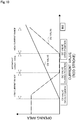
- timing at which the DC valve 53 transitions from the open state to the closed state with the current value in the low current range i.e., the timing of reducing the valve opening degree
- timing at which the CS valve 50 transitions from the closed state to the open state as illustrated in FIG. 10 .
- first land portion 51a and the second land portion 51b of the rod 51 may be configured in such a manner that rings as other bodies are fixed to the rod 51.
- the coil spring 54 is not limited to a compression spring, and may be a tension spring or may be in other shapes than a coil shape.
- the coil spring 54 may be set to have a greater shrinkage allowance than those of the coil spring 85 of the solenoid 80 and the coil spring 63 of the pressure-sensitive body 61, and maximization of the degree of opening of the DC valve 53 is not necessarily restricted.
- the left end 51f of the rod 51 in the axial direction may be set to have such a length in the axial direction that the left end 51f contacts the bottom surface of the recessed portion 70b of the adaptor 70 at, e.g., the timing of opening (fully opening) the CS valve 50, and accordingly, maximization of the degree of opening of the DC valve 53 may be restricted.
- the left end 51f of the rod 51 in the axial direction may directly contact, without arranging the coil spring 54, the recessed portion 70b of the adaptor 70 forming the pressure-sensitive body 61 to open/close the CS valve 50.
- first valve housing 10 and the second valve housing 11 may be integrally formed.
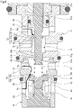
- arrangement of the second Pc port 15 and the Pd port 16 formed at the second valve housing 11 may be reversed, and as illustrated in FIG. 9 , each port may be formed in the order of the second Pc port 15, the Pd port 16, the Ps port 13, and the first Pc port 14 from the solenoid 80 side.
- the pressure-sensitive body 61 does not necessarily use the coil spring therein.
Landscapes
- Engineering & Computer Science (AREA)
- General Engineering & Computer Science (AREA)
- Mechanical Engineering (AREA)
- Physics & Mathematics (AREA)
- Electromagnetism (AREA)
- Magnetically Actuated Valves (AREA)
- Multiple-Way Valves (AREA)
- Compressors, Vaccum Pumps And Other Relevant Systems (AREA)
Abstract
Description
- The present invention relates to a capacity control valve configured to variably control a working fluid capacity, and for example, relates to a capacity control valve configured to control, according to a pressure, a discharge amount of a variable displacement compressor used for an air-conditioning system of an automobile.
- A variable displacement compressor used for, e.g., an air-conditioning system of an automobile includes, for example, a rotary shaft to be rotatably driven by an engine, a swash plate coupled such that an inclination angle thereof with respect to the rotary shaft is variable, and a compression piston coupled to the swash plate. The inclination angle of the swash plate is changed, and accordingly, a stroke amount of the piston is changed. In this manner, a fluid discharge amount is controlled. Using a capacity control valve to be openably driven by electromagnetic force, the variable displacement compressor can control the internal pressure of a control chamber as necessary to continuously change the inclination angle of the swash plate while utilizing a suction pressure Ps of a suction chamber for sucking fluid, a discharge pressure Pd of a discharge chamber for discharging fluid pressurized by the piston, and a control pressure Pc of the control chamber housing the swash plate (see Patent Citations 1, 2, and 3).
- In continuous drive (hereinafter sometimes merely referred to as "in continuous drive") of the variable displacement compressor, energization of the capacity control valve is controlled by a control computer, and the capacity control valve moves a valve body in an axial direction by electromagnetic force generated by a solenoid to perform the normal control of opening/closing a main valve to adjust the control pressure Pc of the control chamber of the variable displacement compressor.
- For example, a capacity control valve of Patent Citation 1 is configured such that a control chamber is connected to a discharge chamber through a stationary orifice, and controls a CS valve as a main valve to adjust the pressure of the control chamber with a suction pressure. Moreover, a capacity control valve of Patent Citation 2 is configured such that a control chamber is connected to a suction chamber through a stationary orifice, and controls a DC valve as a main valve to adjust the pressure of the control chamber with a discharge pressure. Further, a capacity control valve of Patent Citation 3 controls a CS valve and a DC valve to adjust the pressure of a control chamber.
- In normal control of the capacity control valve, the pressure of the control chamber in the variable displacement compressor is controlled as necessary, and the inclination angle of the swash plate with respect to the rotary shaft is continuously changed. In this manner, the stroke amount of the piston is changed such that the fluid discharge amount for the discharge chamber is controlled, and the air-conditioning system is adjusted to have a desired cooling capacity. Moreover, in a case where the variable displacement compressor is driven with the maximum capacity, the main valve of the capacity control valve is closed such that the pressure of the control chamber decreases, and in this manner, the inclination angle of the swash plate becomes maximum.
-
- Patent Citation 1:
JP 2017-129042 A FIG. 2 ) - Patent Citation 2: Japanese Patent No.
6206274 FIG. 2 ) - Patent Citation 3: Japanese Patent No.
4242624 Page 7,FIG. 1 ) - However, in Patent Citations 1 and 2, the capacity control valve can be configured with a simple configuration. However, the stationary orifice connected to the control chamber of the variable displacement compressor has a constant flow path sectional area. Thus, for adjusting the pressure of the control chamber only by control of the main valve (i.e., the CS valve or the DC valve) in normal control, there is room for improvement in controllability of the control pressure Pc. Moreover, in Patent Citation 3, the CS valve and the DC valve are arranged to enhance controllability. However, Patent Citation 3 fails to describe cooperation of the CS valve and the DC valve, and a favorable control efficiency in normal control cannot be always provided.
- The present invention has been made in view of these problems, and is intended to provide a capacity control valve with a favorable control efficiency in normal control.
- For solving the above-described problems, a capacity control valve according to a first aspect of the present invention is a capacity control valve for controlling a flow rate by energization of a solenoid, including: a valve housing formed with a discharge port through which discharge fluid with a discharge pressure passes, a suction port through which suction fluid with a suction pressure passes, and first and second control ports through which control fluid with a control pressure passes; a rod arranged in the valve housing and driven by the solenoid; a CS valve configured to control a fluid flow between the first control port and the suction port in accordance with a movement of the rod; and a DC valve configured to control a fluid flow between the second control port and the discharge port in accordance with the movement of the rod, wherein in a non-energization state of the solenoid, the CS valve is closed and the DC valve is opened, wherein as the energization of the solenoid becomes larger, the CS valve transitions from a closed state to an open state, and the DC valve is throttled from an open state and thereafter transitions to the open state, and wherein in a maximum current state of the solenoid, the CS valve is opened and the DC valve is opened. According to the aforesaid feature of the first aspect of the present invention, the flow rate is controlled by cooperation of the CS valve and the DC valve, and therefore, the control pressure can be controlled with a favorable efficiency. Moreover, the CS valve and the DC valve transition in opposite directions in a low energization current range, only a CS valve opening degree increases in an intermediate current range, and the CS valve and the DC valve transition in the same direction in a high current range. The control pressure is controlled based on a difference between the amount of adjustment of the control pressure by the CS valve and the amount of adjustment of the control pressure by the DC valve. Thus, the control pressure can be finely controlled in association with a current value. Particularly, as energization current increases, the control pressure can be more finely controlled in association with the current value.
- It may be preferable that a state in which the DC valve is throttled in the energization of the solenoid is a closed state. According to this preferable configuration, a control range according to the energization current for the solenoid is broader in the CS valve than in the DC valve. That is, the CS valve is main, and the DC valve is auxiliary. Thus, a favorable control efficiency is provided.
- It may be preferable that the DC valve has a spool valve structure, and includes a land portion of the rod and a DC valve seat provided at the inner periphery of the valve housing. According to this preferable configuration, the DC valve can be simply configured.
- It may be preferable that the rod is arranged at the inner periphery of the valve housing to partition the suction port and the discharge port. According to this preferable configuration, the capacity control valve can be simply configured.
- It may be preferable that the CS valve includes a pressure-sensitive body and a Cs valve seat, the pressure-sensitive body being arranged in a pressure-sensitive chamber formed with the first control port and configured to bias the rod, the CS valve seat being provided at the valve housing. According to this preferable configuration, a structure in which reactive force provided to the rod according to the suction pressure is increased/decreased is made, and controllability of the control pressure is enhanced.
- It may be preferable that a spring configured to provide biasing force in an axial direction is arranged between the pressure-sensitive body and the rod. According to this preferable configuration, the spring can deformably move in the axial direction. Thus, even if an axial deformable amount of the pressure-sensitive body is small, the DC valve can be reliably operated.
- It may be preferable that the discharge port, the second control port, the suction port, and the first control port or the second control port, the discharge port, the suction port, and the first control port are arranged in description order from a side of the solenoid. According to this preferable configuration, the valve housing can be simply configured.
- A capacity control valve according to a second aspect of the present invention is a capacity control valve for controlling a flow rate by energization of a solenoid, including: a valve housing formed with a discharge port through which discharge fluid with a discharge pressure passes, a suction port through which suction fluid with a suction pressure passes, and first and second control ports through which control fluid with a control pressure passes; a rod arranged in the valve housing, driven by the solenoid, the rod forming a spool valve structure of a DC valve configured to control a fluid flow between the second control port and the discharge port by a land portion arranged at an outer periphery; and a pressure-sensitive body forming a CS valve configured to control a fluid flow between the first control port and the suction port in accordance with a movement of the rod. According to the feature of the second aspect of the present invention, the flow rate is controlled by cooperation of the CS valve and the DC valve, and therefore, the control pressure can be controlled with a favorable efficiency.
-
-
FIG. 1 is a schematic configuration view illustrating a swash plate type variable displacement compressor incorporating a capacity control valve of an embodiment according to the present invention. -
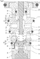
FIG. 2 is a sectional view illustrating a state in which a DC valve is opened and a CS valve is closed in a non-energization state of the capacity control valve of the embodiment. -
FIG. 3 is an enlarged sectional view ofFIG. 2 illustrating a state in which the DC valve is opened and the CS valve is closed in the non-energization state of the capacity control valve of the embodiment. -
FIG. 4 is a sectional view illustrating a state in which the DC valve transitions from an open state to a closed state and the CS valve transitions from a closed state to an open state in an energization state (e.g., corresponding to a low current range) of the capacity control valve of the embodiment. -
FIG. 5 is a sectional view illustrating a state in which the DC valve is closed and the CS valve is opened in the energization state (e.g., corresponding an intermediate current range) of the capacity control valve of the embodiment. -
FIG. 6 is a sectional view illustrating a state in which the DC valve transitions from the closed state to the open state and the CS valve is opened in the energization state (eg.g., corresponding to a high current range) of the capacity control valve of the embodiment. -
FIG. 7 is a graph for describing the opened/closed state of the DC valve and the opened/closed state of the CS valve in association with energization current (e.g., corresponding to a rod stroke) in the capacity control valve of the embodiment. Note that the energization current (corresponding to the stroke) of the horizontal axis is shown in terms of the direction (i.e., a direction from the left to the right inFIG. 2 ) of moving a rod upon current application to a solenoid. -
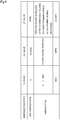
FIG. 8 is a table for describing the energization state of the capacity control valve of the embodiment and the opened/closed states of the CS valve and the DC valve. -
FIG. 9 is a sectional view illustrating a state in which a DC valve is opened and a CS valve is closed in a non-energization state of a capacity control valve of a variation. -
FIG. 10 is a graph for describing an opened/closed state of the DC valve and an opened/closed state of the CS valve in association with energization current (e.g., corresponding to a rod stroke) in the capacity control valve of the variation ofFIG. 9 . Note that the energization current (corresponding to the stroke) of the horizontal axis is shown in terms of the direction (i.e., a direction from the left to the right inFIG. 2 ) of moving a rod upon current application to a solenoid. - Hereinafter, a mode for carrying out a capacity control valve according to the present invention will be described based on an embodiment.
- A capacity control valve according to an embodiment will be described with reference to
FIGS. 1 to 8 . Hereinafter, right and left sides as viewed from a front side ofFIG. 2 will be described as right and left sides of the capacity control valve. - The capacity control valve V of the present invention is incorporated into a variable displacement compressor M used for, e.g., an air-conditioning system of an automobile. The capacity control valve V variably controls the pressure of working fluid (hereinafter merely referred to as "fluid") as refrigerant, thereby controlling a discharge amount of the variable displacement compressor M and adjusting the air-conditioning system to have a desired cooling capacity.
- First, the variable displacement compressor M will be described. As illustrated in
FIG. 1 , the variable displacement compressor M has a casing 1 including a discharge chamber 2, a suction chamber 3, a control chamber 4, andmultiple cylinders 4a. - Moreover, the variable displacement compressor M includes a rotary shaft 5 to be rotatably driven by a not-shown engine placed outside the casing 1, a swash plate 6 coupled in an eccentric state with respect to the rotary shaft 5 by a hinge mechanism 8 in the control chamber 4, and
multiple pistons 7 coupled to the swash plate 6 and each reciprocatably fitted in thecylinders 4a. Using the capacity control valve V to be openably driven by electromagnetic force, the variable displacement compressor M controls the internal pressure of the control chamber 4 as necessary to continuously change an inclination angle of the swash plate 6 while utilizing a suction pressure Ps of the suction chamber 3 for sucking the fluid, a discharge pressure Pd of the discharge chamber 2 for discharging the fluid pressurized by thepiston 7, and a control pressure Pc of the control chamber 4 housing the swash plate 6. In this manner, the variable displacement compressor M changes a stroke amount of thepiston 7 to control the fluid discharge amount. Note that for the sake of convenience in description, the capacity control valve V incorporated into the variable displacement compressor M is not shown inFIG. 1 . - Specifically, as the control pressure Pc in the control chamber 4 increases, the inclination angle of the swash plate 6 with respect to the rotary shaft 5 decreases and the stroke amount of the
piston 7 decreases. However, when such a pressure reaches a pressure of equal to or higher than a certain pressure, the swash plate 6 is brought into a state in which the swash plate 6 is substantially perpendicular to the rotary shaft 5, i.e., a state in which the swash plate 6 is slightly inclined with respect to a direction perpendicular to the rotary shaft 5. In this state, the stroke amount of thepiston 7 is minimum, and pressurization of the fluid in thecylinder 4a by thepiston 7 is minimum. Accordingly, the amount of fluid discharged to the discharge chamber 2 decreases, and the cooling capacity of the air-conditioning system becomes minimum. On the other hand, as the control pressure Pc in the control chamber 4 decreases, the inclination angle of the swash plate 6 with respect to the rotary shaft 5 increases and the stroke amount of thepiston 7 increases. However, when such a pressure reaches a pressure of equal to or lower than a certain pressure, the swash plate 6 is at the maximum inclination angle with respect to the rotary shaft 5. In this state, the stroke amount of thepiston 7 is maximum, and pressurization of the fluid in thecylinder 4a by thepiston 7 is maximum. Accordingly, the amount of fluid discharged to the discharge chamber 2 increases, and the cooling capacity of the air-conditioning system becomes maximum. - As illustrated in
FIG. 2 , the capacity control valve V incorporated into the variable displacement compressor M adjusts current energizing acoil 86 forming asolenoid 80, controls opening/closing of aCS valve 50 and aDC valve 53 in the capacity control valve V, and controls the fluid flowing into the control chamber 4 or flowing out of the control chamber 4. In this manner, the capacity control valve V variably controls the control pressure Pc in the control chamber 4. Note that upon normal control of the capacity control valve V, the discharge pressure Pd is a higher pressure than the control pressure Pc, and the control pressure Pc is a high pressure of equal to or higher than the suction pressure Ps. - In the present embodiment, the
CS valve 50 includes anadaptor 70 forming a pressure-sensitive body 61, and aCS valve seat 10a formed at an inner peripheral surface of afirst valve housing 10 as a valve housing. Atapered end portion 70a formed on the right side of theadaptor 70 in an axial direction contacts or separates from theCS valve seat 10a, and in this manner, theCS valve 50 is opened/closed. TheDC valve 53 has a spool valve structure, and includes arod 51 and aDC valve seat 11a formed at an inner peripheral surface of asecond valve housing 11 as the valve housing. Afirst land portion 51a as a land portion of therod 51 contacts or separates from theDC valve seat 11a, and in this manner, theDC valve 53 is opened/closed. - Subsequently, the structure of the capacity control valve V will be described. As illustrated in
FIG. 2 , the capacity control valve V mainly includes thefirst valve housing 10 and thesecond valve housing 11 made of a metal material or a resin material, therod 51 arranged reciprocatably in the axial direction inside thefirst valve housing 10 and thesecond valve housing 11, the pressure-sensitive body 61 configured to provide rightward biasing force in the axial direction to therod 51 according to the suction pressure Ps in afirst valve chamber 20, and thesolenoid 80 connected to thesecond valve housing 11 and providing drive force to therod 51. - As illustrated in
FIG. 2 , thesolenoid 80 mainly includes acasing 81 having anopening 81a opening leftward in the axial direction, a substantially cylindricalstationary iron core 82 inserted into theopening 81a of thecasing 81 from the left in the axial direction and fixed to an inner diameter side of thecasing 81, therod 51 inserted into thestationary iron core 82 and arranged reciprocatably in the axial direction, amovable iron core 84 fixed to a right end portion of therod 51 in the axial direction, acoil spring 85 provided between thestationary iron core 82 and themovable iron core 84 and biasing themovable iron core 84 rightward in the axial direction, and theexcitation coil 86 wound around the outside of thestationary iron core 82 through a bobbin. - At the
casing 81, a recessedportion 81b recessed rightward in the axial direction on the inner diameter side at a left end in the axial direction is formed. A right end portion of thesecond valve housing 11 in the axial direction is substantially hermetically inserted/fixed into the recessedportion 81b. - The
stationary iron core 82 is made of a rigid body as a magnetic material such as iron or silicon steel, and includes acylindrical portion 82b extending in the axial direction and formed with aninsertion hole 82c into which a right portion of therod 51 in the axial direction is inserted and anannular flange portion 82d extending in an outer diameter direction from an outer peripheral surface of a left end portion of thecylindrical portion 82b in the axial direction. On the left side in the axial direction with respect to theflange portion 82d, an annular recessedportion 82e recessed in an inner diameter direction from an outer peripheral surface of thecylindrical portion 82b is formed. Note that an O-ring 83 is attached to the annular recessedportion 82e, and therefore, thestationary iron core 82 and thesecond valve housing 11 are connected and fixed to each other in a hermetic state. - Moreover, in a state in which a right end surface of the
flange portion 82d in the axial direction contacts a bottom surface of the recessedportion 81b of thecasing 81, thestationary iron core 82 is inserted/fixed into a recessedportion 11c recessed leftward in the axial direction on the inner diameter side at a right end, which is inserted/fixed into the recessedportion 81b of thecasing 81, of thesecond valve housing 11 in the axial direction. - Further, in a state in which the
stationary iron core 82 and thesecond valve housing 11 are attached to thecasing 81, an annular space S is formed between a left end surface of theflange portion 82d of thestationary iron core 82 in the axial direction and the recessedportion 11c of thesecond valve housing 11. Note that the space S is communicated with theinsertion hole 82c inside thestationary iron core 82 through a through-hole 82a extending in a radial direction between theflange portion 82d and the annular recessedportion 82e at thecylindrical portion 82b of thestationary iron core 82. - As illustrated in
FIG. 2 , aPs port 13 as a suction port communicated with the suction chamber 3 of the variable displacement compressor M and afirst Pc port 14 as a first control port communicated with the control chamber 4 of the variable displacement compressor M are formed at thefirst valve housing 10. Moreover, asecond Pc port 15 as a second control port communicated with the control chamber 4 of the variable displacement compressor M and aPd port 16 as a discharge port communicated with the discharge chamber 2 of the variable displacement compressor M are formed at thesecond valve housing 11. Note that these ports are, from asolenoid 80 side, formed in the order of thePd port 16, thesecond Pc port 15, thePs port 13, and thefirst Pc port 14. - Moreover, an outer diameter portion at a right end of the
first valve housing 10 in the axial direction is recessed leftward in the axial direction to form astep portion 10b, and a left end portion of thesecond valve housing 11 in the axial direction is fitted onto such an outer diameter portion from the right in the axial direction such that thefirst valve housing 10 is connected and fixed in a hermetic state. Further, apartition adjustment member 12 is substantially hermetically press-fitted in a left end portion of thefirst valve housing 10 in the axial direction, and therefore, thefirst valve housing 10 is in a substantially cylindrical shape with a bottom. Note that thepartition adjustment member 12 adjusts an installation position of thefirst valve housing 10 in the axial direction so that the biasing force of the pressure-sensitive body 61 can be adjusted. - The
rod 51 is arranged reciprocatably in the axial direction in thefirst valve housing 10 and thesecond valve housing 11, and at part of the inner peripheral surface of thesecond valve housing 11, a small-diameter guide surface 11b is formed so that an outer peripheral surface of asecond land portion 51b (seeFIGS. 3 to 6 ) of therod 51 can slidably contact theguide surface 11b in a substantially hermetic state. - Moreover, in the
first valve housing 10, thefirst valve chamber 20 which is communicated with thePs port 13 and in which a left end portion of therod 51 in the axial direction is arranged and a pressure-sensitive chamber 60 which is communicated with thefirst Pc port 14 and in which the pressure-sensitive body 61 is arranged are formed. Further, in thesecond valve housing 11, asecond valve chamber 30 which is communicated with thesecond Pc port 15 and in which thesecond land portion 51b (seeFIGS. 3 to 6 ) of therod 51 is arranged and athird valve chamber 40 which is communicated with thePd port 16, in which thefirst land portion 51a of therod 51 is arranged, and which is arranged on thesolenoid 80 side of thesecond valve housing 11 are formed. - Note that the
first valve chamber 20 is defined by an outer peripheral surface at a left end portion of therod 51 in the axial direction, an inner peripheral surface on the right side in the axial direction with respect to theCS valve seat 10a of thefirst valve housing 10, and an inner surface of a recessedportion 11d recessed rightward in the axial direction on the inner diameter side at a left end of thesecond valve housing 11 in the axial direction. Further, in a state in which thefirst valve housing 10 and thesecond valve housing 11 are connected and fixed to each other, thefirst valve chamber 20 and thesecond valve chamber 30 are partitioned by thesecond land portion 51b of therod 51. Moreover, thesecond valve chamber 30 and thethird valve chamber 40 are defined by an outer peripheral surface on the right side in the axial direction with respect to thesecond land portion 51b of therod 51 and the inner peripheral surface of thesecond valve housing 11. When theDC valve 53 is closed, thesecond valve chamber 30 and thethird valve chamber 40 are separated from each other. When theDC valve 53 is opened, thesecond valve chamber 30 and thethird valve chamber 40 are communicated with each other. - Further, a through-hole 11e extending in the axial direction from the recessed
portion 11c on the right side in the axial direction to the recessedportion 11d on the left side in the axial direction is formed at thesecond valve housing 11, and thefirst valve chamber 20 and the space S are communicated with each other through the through-hole 11e. Thus, the suction pressure Ps of the suction chamber 3 is introduced into the right side in the axial direction as the back side of themovable iron core 84 forming thesolenoid 80 through thePs port 13, thefirst valve chamber 20, the through-hole 11e of thesecond valve housing 11, the space S, and the through-hole 82a and theinsertion hole 82c of thestationary iron core 82, and accordingly, pressure on both sides of therod 51 in the axial direction is balanced. - As illustrated in
FIG. 2 , the pressure-sensitive body 61 mainly includes abellows core 62 having a built-incoil spring 63, and theadaptor 70 provided at a right end of thebellows core 62 in the axial direction. A left end of thebellows core 62 in the axial direction is fixed to thepartition adjustment member 12. - Moreover, the pressure-
sensitive body 61 is arranged in the pressure-sensitive chamber 60, and by the biasing force of moving theadaptor 70 rightward in the axial direction by thecoil spring 63 and thebellows core 62, thetapered end portion 70a of theadaptor 70 sits on theCS valve seat 10a of thefirst valve housing 10. - As illustrated in
FIGS. 3 to 6 , therod 51 mainly includes a large-diameter portion 51c fixed to the movable iron core 84 (seeFIG. 2 ) at a right end portion in the axial direction, a first small-diameter portion 51d formed with a smaller diameter than that of the large-diameter portion 51c on the left side of the large-diameter portion 51c in the axial direction, and a second small-diameter portion 51e formed with a smaller diameter than that of the first small-diameter portion 51d on the left side of the first small-diameter portion 51d in the axial direction. At the second small-diameter portion 51e, the circular ring-shapedfirst land portion 51a and the circular ring-shapedsecond land portion 51b extending in the outer diameter direction are formed. A portion between thefirst land portion 51a and thesecond land portion 51b in the axial direction is in a shape recessed in an annular shape in the inner diameter direction, and a portion on the left side in the axial direction with respect to thesecond land portion 51b is in a shape with a small diameter. - The
first land portion 51a is in a trapezoidal shape as viewed in the section such that a side portion extending in the inner diameter direction from the left side of an outerperipheral portion 51h in the axial direction is perpendicular to the axial direction of therod 51 and a side portion extending in the inner diameter direction from the right side of the outerperipheral portion 51h in the axial direction is formed in a tapered shape with respect to the axial direction of therod 51. The length of the outerperipheral portion 51h in the axial direction is set substantially equal to the length of theDC valve seat 11a in the axial direction, theDC valve seat 11a being forming at the inner peripheral surface of thesecond valve housing 11. - Moreover, a
left end 51f of therod 51 in the axial direction, i.e., theleft end 51f of the second small-diameter portion 51e in the axial direction, is separated from a bottom surface of a recessedportion 70b recessed leftward in the axial direction on the inner diameter side at a right end of theadaptor 70 in the axial direction. Acoil spring 54 as a spring is fitted onto a left end portion of the second small-diameter portion 51e in the axial direction. Thus, in an energization state of the capacity control valve V, the leftward drive force of thesolenoid 80 in the axial direction acts on the pressure-sensitive body 61, and rightward reactive force in the axial direction is received from the pressure-sensitive body 61. - Further, a left end of the
coil spring 54 in the axial direction contacts the bottom surface of the recessedportion 70b of theadaptor 70, and a right end of thecoil spring 54 in the axial direction contacts aside portion 51g of thesecond land portion 51b of therod 51 on the left side in the axial direction. - Subsequently, operation of the capacity control valve V and operation of opening/closing mechanisms of the
CS valve 50 and theDC valve 53 by movement of therod 51 in the axial direction will be described. - First, a non-energization state of the capacity control valve V will be described. As illustrated in
FIGS. 2 and3 , in the non-energization state of the capacity control valve V, biasing force Fsp1 of thecoil spring 85 forming thesolenoid 80, the biasing force Fbel of the pressure-sensitive body 61 (formed by thebellows core 62 and the coil spring 63), and biasing force Fsp2 of thecoil spring 54 arranged between the pressure-sensitive body 61 and therod 51 act rightward in the axial direction on therod 51. That is, force Frod = Fsp1 + Fbel + Fsp2 acts on therod 51, supposing that the rightward direction is a positive direction. Thus, thetapered end portion 70a of theadaptor 70 sits on theCS valve seat 10a of thefirst valve housing 10, theCS valve 50 is closed (e.g., fully closed), thefirst land portion 51a of therod 51 is separated rightward in the axial direction from theDC valve seat 11a of thesecond valve housing 11, and theDC valve 53 is opened. Moreover, in this state, the degree of elongation of thecoil spring 54 is maximum. - As described above, in a non-energization state of the
solenoid 80, theCS valve 50 is closed (e.g., fully closed), and theDC valve 53 is opened. In a state in which theCS valve 50 is closed, the opening area of theDC valve 53, i.e., the degree of opening of theDC valve 53, is maximum (seeFIGS. 7 and8 ). - Next, the energization state of the capacity control valve V will be described. As illustrated in
FIG. 4 , when electromagnetic force Fsol1 generated by application of current (e.g., a current value in a low current range) to thesolenoid 80 exceeds the force Frod in a normal energization state (e.g., corresponding to a normal control, in so-called duty control) of the capacity control valve V, themovable iron core 84 is attracted to astationary iron core 82 side, i.e., the left side in the axial direction, against the biasing force of thecoil spring 85 forming thesolenoid 80, therod 51 fixed to themovable iron core 84 moves leftward in the axial direction, and the pressure-sensitive body 61 is pressed and contracts leftward in the axial direction through thecoil spring 54. Thus, thetapered end portion 70a of theadaptor 70 is separated from theCS valve seat 10a of thefirst valve housing 10, and theCS valve 50 transitions from a closed state (e.g., a fully-closed state) to an open state. Moreover, thefirst land portion 51a of therod 51 approaches from the right side of theDC valve seat 11a of thesecond valve housing 11 in the axial direction, and therefore, the degree of opening of theDC valve 53 is reduced (seeFIGS. 7 and8 ). - As illustrated in
FIG. 5 , when energization current for thesolenoid 80 is increased to a current value in an intermediate current range and theCS valve 50 is opened to a predetermined valve opening degree, i.e., the degree of opening of theCS valve 50 is increased, thefirst land portion 51a of therod 51 and theDC valve seat 11a of thesecond valve housing 11 overlap with each other as viewed in the radial direction. Accordingly, the outerperipheral portion 51h of thefirst land portion 51a of therod 51 sits on theDC valve seat 11a of thesecond valve housing 11, and theDC valve 53 transitions from an open state, i.e., a state in which the valve opening degree is reduced, to a closed state (e.g., a fully-closed state) (seeFIGS. 7 and8 ). In this state, thecoil spring 54 contracts in the axial direction. - Further, when the energization current for the
solenoid 80 is increased to a current value in a high current range and theCS valve 50 is opened to equal to or higher than the predetermined valve opening degree, i.e., the degree of opening of theCS valve 50 is increased, thefirst land portion 51a of therod 51 is separated leftward in the axial direction from theDC valve seat 11a of thesecond valve housing 11, and theDC valve 53 transitions from the closed state (e.g., the fully-closed state) to the open state (seeFIGS. 7 and8 ). - According to such a configuration, a refrigerant flow rate is controlled by cooperation of the
CS valve 50 and theDC valve 53 in the normal control of the capacity control valve V, and therefore, the control pressure Pc can be efficiently controlled. Further, as the energization current (corresponding to the current value) for thesolenoid 80 increases, i.e., the stroke of therod 51 increases, theCS valve 50 transitions from the closed state (e.g., the fully-closed state) to the open state. Moreover, the degree of opening of theDC valve 53 is reduced from that in the open state, and theDC valve 53 is closed (e.g., fully closed). Thereafter, theDC valve 53 transitions to the open state (seeFIG. 7 ). That is, the degree of opening of theCS valve 50 and the degree of opening of theDC valve 53 in association with an increase in the energization current for thesolenoid 80 transition in opposite directions in the low current range, only the CS valve opening degree increases in the intermediate current range, and the degree of opening of theCS valve 50 and the degree of opening of theDC valve 53 transition in the same direction in the high current range. The control pressure Pc is controlled based on a difference between the amount of adjustment of the control pressure Pc by theCS valve 50 and the amount of adjustment of the control pressure Pc by theDC valve 53. Thus, the control pressure Pc can be finely controlled in association with the current value. Particularly, as the energization current increases, the control pressure Pc can be more finely controlled in association with the current value. - Moreover, it is configured such that when the energization current for the
solenoid 80 is the current value in the intermediate current range, theDC valve 53 is closed (e.g., fully closed). Thus, a control range of the control pressure Pc by theCS valve 50 in association with the energization current for thesolenoid 80 is broader than a control range of the control pressure Pc by theDC valve 53. That is, control of the refrigerant flow rate from thefirst Pc port 14 to thePs port 13 by theCS valve 50 with a smaller required refrigerant flow rate is main, and control of the refrigerant flow rate from thePd port 16 to thesecond Pc port 15 by theDC valve 53 with a greater required refrigerant flow rate is auxiliary. Thus, an internal circulating refrigerant flow rate in the normal control of the capacity control valve V can be reduced, and a favorable efficiency for controlling the control pressure Pc is provided. Consequently, an operation efficiency of the variable displacement compressor M can be enhanced. - Further, the
DC valve 53 has the spool valve structure formed by thefirst land portion 51a of therod 51 and theDC valve seat 11a provided at the inner periphery of thesecond valve housing 11. Thus, therod 51 strokes a predetermined amount or more in the axial direction, and accordingly, theDC valve 53 is brought into the closed state. Consequently, theDC valve 53 can be reliably closed. Further, when the energization current for thesolenoid 80 is, for example, the current value in the intermediate current range, even if therod 51 slightly moves in the axial direction due to, e.g., disturbance such as vibration, theDC valve 53 is maintained in the closed state. Thus, the capacity control valve V has resistance to the disturbance, and exhibits favorable control accuracy. - In a state in which the
first valve housing 10 and thesecond valve housing 11 are connected and fixed to each other, thefirst valve chamber 20 communicated with thePs port 13 and thesecond valve chamber 30 communicated with thesecond Pc port 15 are partitioned by thesecond land portion 51b of therod 51, and therefore, the capacity control valve V can be simply configured. - Moreover, the
rod 51 is biased rightward in the axial direction, i.e., toward thesolenoid 80 side, by thecoil spring 54, and therefore, the open state of theDC valve 53 can be reliably held in the non-energization state of the capacity control valve V. Further, therod 51 is configured such that the outer peripheral surface of thesecond land portion 51b and theguide surface 11b of thesecond valve housing 11 slide on each other, and therefore, movement of therod 51 in the axial direction can be stabilized. - Further, the
CS valve 50 includes the pressure-sensitive body 61 arranged in the pressure-sensitive chamber 60 formed with thefirst Pc port 14 and configured to bias therod 51 rightward in the axial direction through thecoil spring 54 and theCS valve seat 10a provided at thefirst valve housing 10. Thus, a structure in which the reactive force provided to therod 51 through thecoil spring 54 according to the suction pressure Ps of thefirst valve chamber 20 is increased/decreased is made, and controllability of the control pressure Pc is enhanced. - In addition, the
coil spring 54 configured to provide the biasing force in the axial direction is arranged between the pressure-sensitive body 61 and therod 51, and therefore, thecoil spring 54 can deformably move in the axial direction in association with movement of therod 51 in the axial direction. Thus, even if an axial deformable amount of the pressure-sensitive body 61 is small, theDC valve 53 can be reliably operated. - The embodiment of the present invention has been described above with reference to the drawings, but specific configurations are not limited to such an embodiment. Even changes and additions made without departing from the gist of the present invention are included in the present invention.
- For example, the timing of opening/closing the
DC valve 53 by the stroke of therod 51 may be adjusted as necessary in such a manner that arrangement of thefirst land portion 51a in the axial direction at therod 51, a formation position of theDC valve seat 11a in the axial direction at thesecond valve housing 11, or the length of the outerperipheral portion 51h of thefirst land portion 51a or theDC valve seat 11a in the axial direction is changed. For example, as illustrated inFIG. 9 , a distance in the axial direction between the outerperipheral portion 51h of thefirst land portion 51a and theDC valve seat 11a may be longer than that in the above-described embodiment. With such a configuration of the variation, timing at which theDC valve 53 transitions from the open state to the closed state with the current value in the low current range, i.e., the timing of reducing the valve opening degree, can be delayed as compared to timing at which theCS valve 50 transitions from the closed state to the open state as illustrated inFIG. 10 . - Moreover, the
first land portion 51a and thesecond land portion 51b of therod 51 may be configured in such a manner that rings as other bodies are fixed to therod 51. - Further, the
coil spring 54 is not limited to a compression spring, and may be a tension spring or may be in other shapes than a coil shape. - In addition, the
coil spring 54 may be set to have a greater shrinkage allowance than those of thecoil spring 85 of thesolenoid 80 and thecoil spring 63 of the pressure-sensitive body 61, and maximization of the degree of opening of theDC valve 53 is not necessarily restricted. Moreover, theleft end 51f of therod 51 in the axial direction may be set to have such a length in the axial direction that theleft end 51f contacts the bottom surface of the recessedportion 70b of theadaptor 70 at, e.g., the timing of opening (fully opening) theCS valve 50, and accordingly, maximization of the degree of opening of theDC valve 53 may be restricted. - Further, the
left end 51f of therod 51 in the axial direction may directly contact, without arranging thecoil spring 54, the recessedportion 70b of theadaptor 70 forming the pressure-sensitive body 61 to open/close theCS valve 50. - In addition, the
first valve housing 10 and thesecond valve housing 11 may be integrally formed. Moreover, arrangement of thesecond Pc port 15 and thePd port 16 formed at thesecond valve housing 11 may be reversed, and as illustrated inFIG. 9 , each port may be formed in the order of thesecond Pc port 15, thePd port 16, thePs port 13, and thefirst Pc port 14 from thesolenoid 80 side. - Further, the pressure-
sensitive body 61 does not necessarily use the coil spring therein. -
- 1
- Casing
- 2
- Discharge chamber
- 3
- Suction chamber
- 4
- Control chamber
- 10
- First valve housing (valve housing)
- 10a
- CS valve seat
- 11
- Second valve housing (valve housing)
- 11a
- DC valve seat
- 11b
- Guide surface
- 12
- Partition adjustment member
- 13
- Ps port (suction port)
- 14
- First Pc port (first control port)
- 15
- Second Pc port (second control port)
- 16
- Pd port (discharge port)
- 20
- First valve chamber
- 30
- Second valve chamber
- 40
- Third valve chamber
- 50
- CS valve
- 51
- Rod
- 51a
- First land portion (land portion)
- 51b
- Second land portion
- 51c
- Large-diameter portion
- 51d
- First small-diameter portion
- 51e
- Second small-diameter portion
- 51f
- Left end in axial direction
- 51h
- Outer peripheral portion
- 51g
- Side portion
- 53
- DC valve
- 54
- Coil spring (spring)
- 60
- Pressure-sensitive chamber
- 61
- Pressure-sensitive body
- 62
- Bellows core
- 63
- Coil spring
- 70
- Adaptor
- 70a
- Tapered end portion
- 70b
- Recessed portion
- 80
- Solenoid
- 82
- Stationary iron core
- 83
- O-ring
- 84
- Movable iron core
- 85
- Coil spring
- Pc
- Control pressure
- Pd
- Discharge pressure
- Ps
- Suction pressure
- V
- Capacity control valve
Claims (8)
- A capacity control valve for controlling a flow rate by energization of a solenoid, comprising:a valve housing formed with a discharge port through which discharge fluid with a discharge pressure passes, a suction port through which suction fluid with a suction pressure passes, and first and second control ports through which control fluid with a control pressure passes;a rod arranged in the valve housing and driven by the solenoid;a CS valve configured to control a fluid flow between the first control port and the suction port in accordance with a movement of the rod; anda DC valve configured to control a fluid flow between the second control port and the discharge port in accordance with the movement of the rod,wherein in a non-energization state of the solenoid, the CS valve is closed and the DC valve is opened,wherein as the energization of the solenoid becomes larger, the CS valve transitions from a closed state to an open state, and the DC valve is throttled from an open state and thereafter transitions to the open state, andwherein in a maximum current state of the solenoid, the CS valve is opened and the DC valve is opened.
- The capacity control valve according to claim 1, wherein
a state in which the DC valve is throttled in the energization of the solenoid is a closed state. - The capacity control valve according to claim 1 or 2, wherein
the DC valve has a spool valve structure, and includes a land portion of the rod and a DC valve seat provided at an inner periphery of the valve housing. - The capacity control valve according to any one of claims 1 to 3, wherein
the rod is arranged at the inner periphery of the valve housing to partition the suction port and the discharge port. - The capacity control valve according to any one of claims 1 to 4, wherein
the CS valve includes a pressure-sensitive body and a Cs valve seat, the pressure-sensitive body being arranged in a pressure-sensitive chamber formed with the first control port and configured to bias the rod, the CS valve seat being provided at the valve housing. - The capacity control valve according to claim 5, wherein
a spring configured to provide biasing force in an axial direction is arranged between the pressure-sensitive body and the rod. - The capacity control valve according to any one of claims 1 to 6, wherein
the discharge port, the second control port, the suction port, and the first control port or the second control port, the discharge port, the suction port, and the first control port are arranged in description order from a side of the solenoid. - A capacity control valve for controlling a flow rate by energization of a solenoid, comprising:a valve housing formed with a discharge port through which discharge fluid with a discharge pressure passes, a suction port through which suction fluid with a suction pressure passes, and first and second control ports through which control fluid with a control pressure passes;a rod arranged in the valve housing so as to be driven by the solenoid, the rod forming a spool valve structure of a DC valve configured to control a fluid flow between the second control port and the discharge port by a land portion arranged at an outer periphery; anda pressure-sensitive body forming a CS valve configured to control a fluid flow between the first control port and the suction port in accordance with a movement of the rod.
Applications Claiming Priority (2)
| Application Number | Priority Date | Filing Date | Title |
|---|---|---|---|
| JP2018149805 | 2018-08-08 | ||
| PCT/JP2019/031069 WO2020032089A1 (en) | 2018-08-08 | 2019-08-07 | Capacity control valve |
Publications (3)
| Publication Number | Publication Date |
|---|---|
| EP3835576A1 true EP3835576A1 (en) | 2021-06-16 |
| EP3835576A4 EP3835576A4 (en) | 2022-03-09 |
| EP3835576B1 EP3835576B1 (en) | 2024-03-27 |
Family
ID=69413740
Family Applications (1)
| Application Number | Title | Priority Date | Filing Date |
|---|---|---|---|
| EP19847395.1A Active EP3835576B1 (en) | 2018-08-08 | 2019-08-07 | Capacity control valve |
Country Status (5)
| Country | Link |
|---|---|
| US (1) | US11473683B2 (en) |
| EP (1) | EP3835576B1 (en) |
| JP (1) | JP7289604B2 (en) |
| CN (1) | CN112513461B (en) |
| WO (1) | WO2020032089A1 (en) |
Families Citing this family (2)
| Publication number | Priority date | Publication date | Assignee | Title |
|---|---|---|---|---|
| US12292130B2 (en) * | 2019-01-21 | 2025-05-06 | Eagle Industry Co., Ltd. | Capacity control valve |
| KR102787648B1 (en) | 2019-10-28 | 2025-03-28 | 이구루코교 가부시기가이샤 | Capacity control valve |
Family Cites Families (63)
| Publication number | Priority date | Publication date | Assignee | Title |
|---|---|---|---|---|
| JPS5862775A (en) | 1981-10-08 | 1983-04-14 | Sankyo Seiki Mfg Co Ltd | Processor for card with magnetic stripe |
| JP3089816B2 (en) | 1992-04-28 | 2000-09-18 | 株式会社豊田自動織機製作所 | Swash plate type variable displacement compressor |
| JPH06200875A (en) | 1993-01-08 | 1994-07-19 | Toyota Autom Loom Works Ltd | Rocking swash plate type variable displacement compressor |
| JP3242496B2 (en) | 1993-07-06 | 2001-12-25 | 株式会社豊田自動織機 | External switching type displacement control valve for variable displacement compressor |
| JPH09144929A (en) | 1995-11-16 | 1997-06-03 | Tosok Corp | Solenoid valve |
| US6010312A (en) | 1996-07-31 | 2000-01-04 | Kabushiki Kaisha Toyoda Jidoshokki Seiksakusho | Control valve unit with independently operable valve mechanisms for variable displacement compressor |
| JP3583951B2 (en) | 1999-06-07 | 2004-11-04 | 株式会社豊田自動織機 | Capacity control valve |
| JP2001073939A (en) | 1999-08-31 | 2001-03-21 | Toyota Autom Loom Works Ltd | Control valve for variable displacement compressor and variable displacement compressor |
| JP2001099060A (en) | 1999-10-04 | 2001-04-10 | Fuji Koki Corp | Control valve for variable displacement compressor |
| JP2001132632A (en) | 1999-11-10 | 2001-05-18 | Toyota Autom Loom Works Ltd | Control valve of variable displacement compressor |
| JP3942851B2 (en) | 2001-07-31 | 2007-07-11 | 株式会社テージーケー | Capacity control valve |
| KR100858604B1 (en) * | 2001-11-30 | 2008-09-17 | 가부시기가이샤 후지고오키 | Control Valve for Variable Capacity Compressors |
| JP4242624B2 (en) | 2002-09-26 | 2009-03-25 | イーグル工業株式会社 | Capacity control valve and control method thereof |
| WO2004065789A1 (en) * | 2003-01-22 | 2004-08-05 | Zexel Valeo Climate Control Corporation | Control valve of variable displacement compressor |
| JP4316955B2 (en) * | 2003-08-11 | 2009-08-19 | イーグル工業株式会社 | Capacity control valve |
| JP2006097665A (en) | 2004-06-28 | 2006-04-13 | Toyota Industries Corp | Capacity control valve in variable displacement compressor |
| JP4431462B2 (en) | 2004-08-10 | 2010-03-17 | 株式会社鷺宮製作所 | Swash plate type variable capacity compressor and electromagnetic control valve |
| CN100516516C (en) | 2005-02-24 | 2009-07-22 | 株式会社丰田自动织机 | Capacity control valve |
| JP2006307828A (en) | 2005-03-31 | 2006-11-09 | Tgk Co Ltd | Control valve for variable displacement compressor |
| CN101410620B (en) | 2006-03-15 | 2011-03-23 | 伊格尔工业股份有限公司 | Capacity control valve |
| JP2007247512A (en) | 2006-03-15 | 2007-09-27 | Toyota Industries Corp | Capacity control valve in variable capacity type compressor |
| JP2008014269A (en) | 2006-07-07 | 2008-01-24 | Toyota Industries Corp | Displacement control valve for variable displacement compressor |
| JP2008202572A (en) | 2007-02-22 | 2008-09-04 | Toyota Industries Corp | Capacity control valve of variable displacement compressor |
| JP4861956B2 (en) | 2007-10-24 | 2012-01-25 | 株式会社豊田自動織機 | Capacity control valve in variable capacity compressor |
| JP2011032916A (en) | 2009-07-31 | 2011-02-17 | Tgk Co Ltd | Control valve |
| KR101099121B1 (en) | 2009-08-19 | 2011-12-27 | 주식회사 두원전자 | Vacuum bellows assembly manufacturing method |
| KR101319565B1 (en) | 2010-03-16 | 2013-10-23 | 이구루코교 가부시기가이샤 | Volume control valve |
| US8757988B2 (en) | 2010-04-29 | 2014-06-24 | Eagle Industry Co., Ltd. | Capacity control valve |
| JP5907432B2 (en) * | 2011-06-15 | 2016-04-26 | イーグル工業株式会社 | Capacity control valve |
| JP5665722B2 (en) | 2011-11-17 | 2015-02-04 | 株式会社豊田自動織機 | Capacity control valve |
| KR101322404B1 (en) | 2012-01-19 | 2013-10-28 | (주)대정고분자산업 | Electric control valve for variable displacement compressor |
| US20150068628A1 (en) | 2012-05-24 | 2015-03-12 | Eagle Industry Co., Ltd. | Capacity control valve |
| JP6064132B2 (en) | 2012-10-09 | 2017-01-25 | 株式会社テージーケー | Compound valve |
| US9714646B2 (en) * | 2012-12-12 | 2017-07-25 | Eagle Industry Co., Ltd. | Capacity control valve |
| JP6020130B2 (en) | 2012-12-19 | 2016-11-02 | 株式会社豊田自動織機 | Variable capacity swash plate compressor |
| EP2952741B1 (en) | 2013-01-31 | 2019-03-13 | Eagle Industry Co., Ltd. | Variable capacity compressor |
| JP6103586B2 (en) | 2013-03-27 | 2017-03-29 | 株式会社テージーケー | Control valve for variable capacity compressor |
| JP6149239B2 (en) * | 2013-06-28 | 2017-06-21 | 株式会社テージーケー | Control valve for variable capacity compressor |
| JP6206274B2 (en) | 2014-03-19 | 2017-10-04 | 株式会社豊田自動織機 | Capacity control valve |
| EP3239570B1 (en) | 2014-12-25 | 2020-05-13 | Eagle Industry Co., Ltd. | Volume control valve |
| JP6264312B2 (en) * | 2015-03-19 | 2018-01-24 | 株式会社豊田自動織機 | Variable capacity swash plate compressor |
| JP6500183B2 (en) * | 2015-04-02 | 2019-04-17 | 株式会社テージーケー | Control valve for variable displacement compressor |
| US20170028462A1 (en) | 2015-07-28 | 2017-02-02 | Primetals Technologies USA LLC | Simple copper tube design for continuous casting process with enhanced rigidity |
| WO2017057160A1 (en) | 2015-09-29 | 2017-04-06 | 株式会社ヴァレオジャパン | Variable displacement compressor control valve |
| JP6383720B2 (en) | 2015-12-16 | 2018-08-29 | 株式会社不二工機 | Control valve for variable displacement compressor |
| JP6663227B2 (en) | 2016-01-19 | 2020-03-11 | サンデン・オートモーティブコンポーネント株式会社 | Displacement control valve for variable displacement compressor |
| JP6500186B2 (en) | 2016-02-25 | 2019-04-17 | 株式会社テージーケー | Control valve for variable displacement compressor |
| WO2017159553A1 (en) | 2016-03-17 | 2017-09-21 | イーグル工業株式会社 | Capacity control valve |
| CN108071824B (en) | 2016-06-13 | 2021-08-10 | 株式会社Tgk | Control valve for variable displacement compressor |
| JP6714274B2 (en) | 2016-06-13 | 2020-06-24 | 株式会社テージーケー | Control valve for variable capacity compressor |
| JP2018021646A (en) | 2016-08-05 | 2018-02-08 | 株式会社鷺宮製作所 | Pressure sensitive control valve |
| JP2018040385A (en) | 2016-09-05 | 2018-03-15 | 株式会社テージーケー | solenoid valve |
| EP3564528B1 (en) | 2016-12-28 | 2022-08-03 | Eagle Industry Co., Ltd. | Capacity control valve |
| JP2018145877A (en) | 2017-03-06 | 2018-09-20 | 株式会社豊田自動織機 | Variable capacity-type swash plate compressor |
| JP6924476B2 (en) | 2017-04-07 | 2021-08-25 | 株式会社テージーケー | Control valve for variable displacement compressor |
| JP6997536B2 (en) | 2017-05-09 | 2022-01-17 | サンデン・オートモーティブコンポーネント株式会社 | Solenoid control valve and variable displacement compressor equipped with it |
| JP2019002384A (en) | 2017-06-19 | 2019-01-10 | サンデン・オートモーティブコンポーネント株式会社 | Variable displacement compressor |
| US11512786B2 (en) | 2017-11-30 | 2022-11-29 | Eagle Industry Co., Ltd. | Capacity control valve and control method for capacity control valve |
| JP7167067B2 (en) | 2018-01-26 | 2022-11-08 | イーグル工業株式会社 | capacity control valve |
| EP3760864B1 (en) | 2018-02-27 | 2022-11-16 | Eagle Industry Co., Ltd. | Capacity control valve |
| US11873805B2 (en) | 2018-08-08 | 2024-01-16 | Eagle Industry Co., Ltd. | Capacity control valve |
| US11053933B2 (en) | 2018-12-13 | 2021-07-06 | Eagle Industry Co., Ltd. | Displacement control valve |
| US11300219B2 (en) | 2020-07-28 | 2022-04-12 | Mahle International Gmbh | Variable-capacity compressor control valve |
-
2019
- 2019-08-07 US US17/259,138 patent/US11473683B2/en active Active
- 2019-08-07 EP EP19847395.1A patent/EP3835576B1/en active Active
- 2019-08-07 JP JP2020535829A patent/JP7289604B2/en active Active
- 2019-08-07 CN CN201980047614.6A patent/CN112513461B/en active Active
- 2019-08-07 WO PCT/JP2019/031069 patent/WO2020032089A1/en not_active Ceased
Also Published As
| Publication number | Publication date |
|---|---|
| JPWO2020032089A1 (en) | 2021-08-12 |
| EP3835576A4 (en) | 2022-03-09 |
| CN112513461A (en) | 2021-03-16 |
| JP7289604B2 (en) | 2023-06-12 |
| US20210270378A1 (en) | 2021-09-02 |
| EP3835576B1 (en) | 2024-03-27 |
| CN112513461B (en) | 2022-12-23 |
| WO2020032089A1 (en) | 2020-02-13 |
| US11473683B2 (en) | 2022-10-18 |
Similar Documents
| Publication | Publication Date | Title |
|---|---|---|
| EP3835578B1 (en) | Capacity control valve | |
| EP3760864B1 (en) | Capacity control valve | |
| EP3822485B1 (en) | Capacity control valve | |
| CN113474553A (en) | Displacement control valve | |
| EP4141259B1 (en) | Capacity control valve | |
| EP3754190A1 (en) | Capacity control valve | |
| EP4148274A1 (en) | Capacity control valve | |
| KR102744360B1 (en) | Capacity control valve | |
| KR102596905B1 (en) | capacity control valve | |
| EP3835576B1 (en) | Capacity control valve | |
| EP3835577B1 (en) | Capacity control valve | |
| EP3822483A1 (en) | Capacity control valve | |
| KR102603184B1 (en) | capacity control valve | |
| EP3879150A1 (en) | Capacity control valve | |
| EP4160015B1 (en) | Capacity control valve | |
| KR102744356B1 (en) | Capacity control valve |
Legal Events
| Date | Code | Title | Description |
|---|---|---|---|
| STAA | Information on the status of an ep patent application or granted ep patent |
Free format text: STATUS: THE INTERNATIONAL PUBLICATION HAS BEEN MADE |
|
| PUAI | Public reference made under article 153(3) epc to a published international application that has entered the european phase |
Free format text: ORIGINAL CODE: 0009012 |
|
| STAA | Information on the status of an ep patent application or granted ep patent |
Free format text: STATUS: REQUEST FOR EXAMINATION WAS MADE |
|
| 17P | Request for examination filed |
Effective date: 20210118 |
|
| AK | Designated contracting states |
Kind code of ref document: A1 Designated state(s): AL AT BE BG CH CY CZ DE DK EE ES FI FR GB GR HR HU IE IS IT LI LT LU LV MC MK MT NL NO PL PT RO RS SE SI SK SM TR |
|
| DAV | Request for validation of the european patent (deleted) | ||
| DAX | Request for extension of the european patent (deleted) | ||
| A4 | Supplementary search report drawn up and despatched |
Effective date: 20220209 |
|
| RIC1 | Information provided on ipc code assigned before grant |
Ipc: F04B 27/18 20060101AFI20220203BHEP |
|
| GRAP | Despatch of communication of intention to grant a patent |
Free format text: ORIGINAL CODE: EPIDOSNIGR1 |
|
| STAA | Information on the status of an ep patent application or granted ep patent |
Free format text: STATUS: GRANT OF PATENT IS INTENDED |
|
| INTG | Intention to grant announced |
Effective date: 20231027 |
|
| GRAS | Grant fee paid |
Free format text: ORIGINAL CODE: EPIDOSNIGR3 |
|
| GRAA | (expected) grant |
Free format text: ORIGINAL CODE: 0009210 |
|
| STAA | Information on the status of an ep patent application or granted ep patent |
Free format text: STATUS: THE PATENT HAS BEEN GRANTED |
|
| AK | Designated contracting states |
Kind code of ref document: B1 Designated state(s): AL AT BE BG CH CY CZ DE DK EE ES FI FR GB GR HR HU IE IS IT LI LT LU LV MC MK MT NL NO PL PT RO RS SE SI SK SM TR |
|
| REG | Reference to a national code |
Ref country code: GB Ref legal event code: FG4D |
|
| REG | Reference to a national code |
Ref country code: CH Ref legal event code: EP |
|
| REG | Reference to a national code |
Ref country code: DE Ref legal event code: R096 Ref document number: 602019049180 Country of ref document: DE |
|
| REG | Reference to a national code |
Ref country code: IE Ref legal event code: FG4D |
|
| PG25 | Lapsed in a contracting state [announced via postgrant information from national office to epo] |
Ref country code: LT Free format text: LAPSE BECAUSE OF FAILURE TO SUBMIT A TRANSLATION OF THE DESCRIPTION OR TO PAY THE FEE WITHIN THE PRESCRIBED TIME-LIMIT Effective date: 20240327 |
|
| REG | Reference to a national code |
Ref country code: LT Ref legal event code: MG9D |
|
| PG25 | Lapsed in a contracting state [announced via postgrant information from national office to epo] |
Ref country code: GR Free format text: LAPSE BECAUSE OF FAILURE TO SUBMIT A TRANSLATION OF THE DESCRIPTION OR TO PAY THE FEE WITHIN THE PRESCRIBED TIME-LIMIT Effective date: 20240628 |
|
| PG25 | Lapsed in a contracting state [announced via postgrant information from national office to epo] |
Ref country code: HR Free format text: LAPSE BECAUSE OF FAILURE TO SUBMIT A TRANSLATION OF THE DESCRIPTION OR TO PAY THE FEE WITHIN THE PRESCRIBED TIME-LIMIT Effective date: 20240327 Ref country code: RS Free format text: LAPSE BECAUSE OF FAILURE TO SUBMIT A TRANSLATION OF THE DESCRIPTION OR TO PAY THE FEE WITHIN THE PRESCRIBED TIME-LIMIT Effective date: 20240627 |
|
| PG25 | Lapsed in a contracting state [announced via postgrant information from national office to epo] |
Ref country code: RS Free format text: LAPSE BECAUSE OF FAILURE TO SUBMIT A TRANSLATION OF THE DESCRIPTION OR TO PAY THE FEE WITHIN THE PRESCRIBED TIME-LIMIT Effective date: 20240627 Ref country code: NO Free format text: LAPSE BECAUSE OF FAILURE TO SUBMIT A TRANSLATION OF THE DESCRIPTION OR TO PAY THE FEE WITHIN THE PRESCRIBED TIME-LIMIT Effective date: 20240627 Ref country code: LT Free format text: LAPSE BECAUSE OF FAILURE TO SUBMIT A TRANSLATION OF THE DESCRIPTION OR TO PAY THE FEE WITHIN THE PRESCRIBED TIME-LIMIT Effective date: 20240327 Ref country code: HR Free format text: LAPSE BECAUSE OF FAILURE TO SUBMIT A TRANSLATION OF THE DESCRIPTION OR TO PAY THE FEE WITHIN THE PRESCRIBED TIME-LIMIT Effective date: 20240327 Ref country code: GR Free format text: LAPSE BECAUSE OF FAILURE TO SUBMIT A TRANSLATION OF THE DESCRIPTION OR TO PAY THE FEE WITHIN THE PRESCRIBED TIME-LIMIT Effective date: 20240628 Ref country code: FI Free format text: LAPSE BECAUSE OF FAILURE TO SUBMIT A TRANSLATION OF THE DESCRIPTION OR TO PAY THE FEE WITHIN THE PRESCRIBED TIME-LIMIT Effective date: 20240327 Ref country code: BG Free format text: LAPSE BECAUSE OF FAILURE TO SUBMIT A TRANSLATION OF THE DESCRIPTION OR TO PAY THE FEE WITHIN THE PRESCRIBED TIME-LIMIT Effective date: 20240327 |
|
| REG | Reference to a national code |
Ref country code: NL Ref legal event code: MP Effective date: 20240327 |
|
| PG25 | Lapsed in a contracting state [announced via postgrant information from national office to epo] |
Ref country code: SE Free format text: LAPSE BECAUSE OF FAILURE TO SUBMIT A TRANSLATION OF THE DESCRIPTION OR TO PAY THE FEE WITHIN THE PRESCRIBED TIME-LIMIT Effective date: 20240327 Ref country code: LV Free format text: LAPSE BECAUSE OF FAILURE TO SUBMIT A TRANSLATION OF THE DESCRIPTION OR TO PAY THE FEE WITHIN THE PRESCRIBED TIME-LIMIT Effective date: 20240327 |
|
| PG25 | Lapsed in a contracting state [announced via postgrant information from national office to epo] |
Ref country code: NL Free format text: LAPSE BECAUSE OF FAILURE TO SUBMIT A TRANSLATION OF THE DESCRIPTION OR TO PAY THE FEE WITHIN THE PRESCRIBED TIME-LIMIT Effective date: 20240327 |
|
| REG | Reference to a national code |
Ref country code: AT Ref legal event code: MK05 Ref document number: 1670147 Country of ref document: AT Kind code of ref document: T Effective date: 20240327 |
|
| PG25 | Lapsed in a contracting state [announced via postgrant information from national office to epo] |
Ref country code: NL Free format text: LAPSE BECAUSE OF FAILURE TO SUBMIT A TRANSLATION OF THE DESCRIPTION OR TO PAY THE FEE WITHIN THE PRESCRIBED TIME-LIMIT Effective date: 20240327 |
|
| PG25 | Lapsed in a contracting state [announced via postgrant information from national office to epo] |
Ref country code: IS Free format text: LAPSE BECAUSE OF FAILURE TO SUBMIT A TRANSLATION OF THE DESCRIPTION OR TO PAY THE FEE WITHIN THE PRESCRIBED TIME-LIMIT Effective date: 20240727 |
|
| PG25 | Lapsed in a contracting state [announced via postgrant information from national office to epo] |
Ref country code: SM Free format text: LAPSE BECAUSE OF FAILURE TO SUBMIT A TRANSLATION OF THE DESCRIPTION OR TO PAY THE FEE WITHIN THE PRESCRIBED TIME-LIMIT Effective date: 20240327 Ref country code: PT Free format text: LAPSE BECAUSE OF FAILURE TO SUBMIT A TRANSLATION OF THE DESCRIPTION OR TO PAY THE FEE WITHIN THE PRESCRIBED TIME-LIMIT Effective date: 20240729 |
|
| PG25 | Lapsed in a contracting state [announced via postgrant information from national office to epo] |
Ref country code: ES Free format text: LAPSE BECAUSE OF FAILURE TO SUBMIT A TRANSLATION OF THE DESCRIPTION OR TO PAY THE FEE WITHIN THE PRESCRIBED TIME-LIMIT Effective date: 20240327 |
|
| PG25 | Lapsed in a contracting state [announced via postgrant information from national office to epo] |
Ref country code: EE Free format text: LAPSE BECAUSE OF FAILURE TO SUBMIT A TRANSLATION OF THE DESCRIPTION OR TO PAY THE FEE WITHIN THE PRESCRIBED TIME-LIMIT Effective date: 20240327 Ref country code: CZ Free format text: LAPSE BECAUSE OF FAILURE TO SUBMIT A TRANSLATION OF THE DESCRIPTION OR TO PAY THE FEE WITHIN THE PRESCRIBED TIME-LIMIT Effective date: 20240327 |
|
| PG25 | Lapsed in a contracting state [announced via postgrant information from national office to epo] |
Ref country code: AT Free format text: LAPSE BECAUSE OF FAILURE TO SUBMIT A TRANSLATION OF THE DESCRIPTION OR TO PAY THE FEE WITHIN THE PRESCRIBED TIME-LIMIT Effective date: 20240327 |
|
| PG25 | Lapsed in a contracting state [announced via postgrant information from national office to epo] |
Ref country code: PL Free format text: LAPSE BECAUSE OF FAILURE TO SUBMIT A TRANSLATION OF THE DESCRIPTION OR TO PAY THE FEE WITHIN THE PRESCRIBED TIME-LIMIT Effective date: 20240327 |
|
| PG25 | Lapsed in a contracting state [announced via postgrant information from national office to epo] |
Ref country code: SK Free format text: LAPSE BECAUSE OF FAILURE TO SUBMIT A TRANSLATION OF THE DESCRIPTION OR TO PAY THE FEE WITHIN THE PRESCRIBED TIME-LIMIT Effective date: 20240327 |
|
| PG25 | Lapsed in a contracting state [announced via postgrant information from national office to epo] |
Ref country code: SM Free format text: LAPSE BECAUSE OF FAILURE TO SUBMIT A TRANSLATION OF THE DESCRIPTION OR TO PAY THE FEE WITHIN THE PRESCRIBED TIME-LIMIT Effective date: 20240327 Ref country code: SK Free format text: LAPSE BECAUSE OF FAILURE TO SUBMIT A TRANSLATION OF THE DESCRIPTION OR TO PAY THE FEE WITHIN THE PRESCRIBED TIME-LIMIT Effective date: 20240327 Ref country code: RO Free format text: LAPSE BECAUSE OF FAILURE TO SUBMIT A TRANSLATION OF THE DESCRIPTION OR TO PAY THE FEE WITHIN THE PRESCRIBED TIME-LIMIT Effective date: 20240327 Ref country code: PT Free format text: LAPSE BECAUSE OF FAILURE TO SUBMIT A TRANSLATION OF THE DESCRIPTION OR TO PAY THE FEE WITHIN THE PRESCRIBED TIME-LIMIT Effective date: 20240729 Ref country code: PL Free format text: LAPSE BECAUSE OF FAILURE TO SUBMIT A TRANSLATION OF THE DESCRIPTION OR TO PAY THE FEE WITHIN THE PRESCRIBED TIME-LIMIT Effective date: 20240327 Ref country code: IS Free format text: LAPSE BECAUSE OF FAILURE TO SUBMIT A TRANSLATION OF THE DESCRIPTION OR TO PAY THE FEE WITHIN THE PRESCRIBED TIME-LIMIT Effective date: 20240727 Ref country code: ES Free format text: LAPSE BECAUSE OF FAILURE TO SUBMIT A TRANSLATION OF THE DESCRIPTION OR TO PAY THE FEE WITHIN THE PRESCRIBED TIME-LIMIT Effective date: 20240327 Ref country code: EE Free format text: LAPSE BECAUSE OF FAILURE TO SUBMIT A TRANSLATION OF THE DESCRIPTION OR TO PAY THE FEE WITHIN THE PRESCRIBED TIME-LIMIT Effective date: 20240327 Ref country code: CZ Free format text: LAPSE BECAUSE OF FAILURE TO SUBMIT A TRANSLATION OF THE DESCRIPTION OR TO PAY THE FEE WITHIN THE PRESCRIBED TIME-LIMIT Effective date: 20240327 Ref country code: AT Free format text: LAPSE BECAUSE OF FAILURE TO SUBMIT A TRANSLATION OF THE DESCRIPTION OR TO PAY THE FEE WITHIN THE PRESCRIBED TIME-LIMIT Effective date: 20240327 |
|
| PG25 | Lapsed in a contracting state [announced via postgrant information from national office to epo] |
Ref country code: IT Free format text: LAPSE BECAUSE OF FAILURE TO SUBMIT A TRANSLATION OF THE DESCRIPTION OR TO PAY THE FEE WITHIN THE PRESCRIBED TIME-LIMIT Effective date: 20240327 |
|
| PG25 | Lapsed in a contracting state [announced via postgrant information from national office to epo] |
Ref country code: IT Free format text: LAPSE BECAUSE OF FAILURE TO SUBMIT A TRANSLATION OF THE DESCRIPTION OR TO PAY THE FEE WITHIN THE PRESCRIBED TIME-LIMIT Effective date: 20240327 |
|
| REG | Reference to a national code |
Ref country code: DE Ref legal event code: R097 Ref document number: 602019049180 Country of ref document: DE |
|
| PG25 | Lapsed in a contracting state [announced via postgrant information from national office to epo] |
Ref country code: DK Free format text: LAPSE BECAUSE OF FAILURE TO SUBMIT A TRANSLATION OF THE DESCRIPTION OR TO PAY THE FEE WITHIN THE PRESCRIBED TIME-LIMIT Effective date: 20240327 |
|
| PG25 | Lapsed in a contracting state [announced via postgrant information from national office to epo] |
Ref country code: DK Free format text: LAPSE BECAUSE OF FAILURE TO SUBMIT A TRANSLATION OF THE DESCRIPTION OR TO PAY THE FEE WITHIN THE PRESCRIBED TIME-LIMIT Effective date: 20240327 |
|
| PLBE | No opposition filed within time limit |
Free format text: ORIGINAL CODE: 0009261 |
|
| STAA | Information on the status of an ep patent application or granted ep patent |
Free format text: STATUS: NO OPPOSITION FILED WITHIN TIME LIMIT |
|
| 26N | No opposition filed |
Effective date: 20250103 |
|
| REG | Reference to a national code |
Ref country code: CH Ref legal event code: PL |
|
| PG25 | Lapsed in a contracting state [announced via postgrant information from national office to epo] |
Ref country code: LU Free format text: LAPSE BECAUSE OF NON-PAYMENT OF DUE FEES Effective date: 20240807 |
|
| GBPC | Gb: european patent ceased through non-payment of renewal fee |
Effective date: 20240807 |
|
| PG25 | Lapsed in a contracting state [announced via postgrant information from national office to epo] |
Ref country code: CH Free format text: LAPSE BECAUSE OF NON-PAYMENT OF DUE FEES Effective date: 20240831 Ref country code: MC Free format text: LAPSE BECAUSE OF FAILURE TO SUBMIT A TRANSLATION OF THE DESCRIPTION OR TO PAY THE FEE WITHIN THE PRESCRIBED TIME-LIMIT Effective date: 20240327 Ref country code: SI Free format text: LAPSE BECAUSE OF FAILURE TO SUBMIT A TRANSLATION OF THE DESCRIPTION OR TO PAY THE FEE WITHIN THE PRESCRIBED TIME-LIMIT Effective date: 20240327 |
|
| REG | Reference to a national code |
Ref country code: BE Ref legal event code: MM Effective date: 20240831 |
|
| PG25 | Lapsed in a contracting state [announced via postgrant information from national office to epo] |
Ref country code: GB Free format text: LAPSE BECAUSE OF NON-PAYMENT OF DUE FEES Effective date: 20240807 |
|
| PG25 | Lapsed in a contracting state [announced via postgrant information from national office to epo] |
Ref country code: BE Free format text: LAPSE BECAUSE OF NON-PAYMENT OF DUE FEES Effective date: 20240831 |
|
| PG25 | Lapsed in a contracting state [announced via postgrant information from national office to epo] |
Ref country code: FR Free format text: LAPSE BECAUSE OF NON-PAYMENT OF DUE FEES Effective date: 20240831 |
|
| PG25 | Lapsed in a contracting state [announced via postgrant information from national office to epo] |
Ref country code: IE Free format text: LAPSE BECAUSE OF NON-PAYMENT OF DUE FEES Effective date: 20240807 |
|
| PGFP | Annual fee paid to national office [announced via postgrant information from national office to epo] |
Ref country code: DE Payment date: 20250702 Year of fee payment: 7 |
|
| PG25 | Lapsed in a contracting state [announced via postgrant information from national office to epo] |
Ref country code: CY Free format text: LAPSE BECAUSE OF FAILURE TO SUBMIT A TRANSLATION OF THE DESCRIPTION OR TO PAY THE FEE WITHIN THE PRESCRIBED TIME-LIMIT; INVALID AB INITIO Effective date: 20190807 |
|
| PG25 | Lapsed in a contracting state [announced via postgrant information from national office to epo] |
Ref country code: HU Free format text: LAPSE BECAUSE OF FAILURE TO SUBMIT A TRANSLATION OF THE DESCRIPTION OR TO PAY THE FEE WITHIN THE PRESCRIBED TIME-LIMIT; INVALID AB INITIO Effective date: 20190807 |