EP3835451A1 - Thermal barrier coating - Google Patents
Thermal barrier coating Download PDFInfo
- Publication number
- EP3835451A1 EP3835451A1 EP20208358.0A EP20208358A EP3835451A1 EP 3835451 A1 EP3835451 A1 EP 3835451A1 EP 20208358 A EP20208358 A EP 20208358A EP 3835451 A1 EP3835451 A1 EP 3835451A1
- Authority
- EP
- European Patent Office
- Prior art keywords
- layer
- ceramic
- nucleation
- thermal barrier
- barrier coating
- Prior art date
- Legal status (The legal status is an assumption and is not a legal conclusion. Google has not performed a legal analysis and makes no representation as to the accuracy of the status listed.)
- Withdrawn
Links
- 239000012720 thermal barrier coating Substances 0.000 title claims abstract description 47
- 239000000919 ceramic Substances 0.000 claims abstract description 118
- 230000006911 nucleation Effects 0.000 claims abstract description 65
- 238000010899 nucleation Methods 0.000 claims abstract description 65
- PNEYBMLMFCGWSK-UHFFFAOYSA-N aluminium oxide Inorganic materials [O-2].[O-2].[O-2].[Al+3].[Al+3] PNEYBMLMFCGWSK-UHFFFAOYSA-N 0.000 claims abstract description 29
- 239000000758 substrate Substances 0.000 claims abstract description 17
- 238000000576 coating method Methods 0.000 claims abstract description 13
- 239000011248 coating agent Substances 0.000 claims abstract description 12
- GWEVSGVZZGPLCZ-UHFFFAOYSA-N Titan oxide Chemical compound O=[Ti]=O GWEVSGVZZGPLCZ-UHFFFAOYSA-N 0.000 claims description 44
- 238000000151 deposition Methods 0.000 claims description 41
- MCMNRKCIXSYSNV-UHFFFAOYSA-N Zirconium dioxide Chemical compound O=[Zr]=O MCMNRKCIXSYSNV-UHFFFAOYSA-N 0.000 claims description 35
- 238000000034 method Methods 0.000 claims description 28
- 241000588731 Hafnia Species 0.000 claims description 22
- CJNBYAVZURUTKZ-UHFFFAOYSA-N hafnium(IV) oxide Inorganic materials O=[Hf]=O CJNBYAVZURUTKZ-UHFFFAOYSA-N 0.000 claims description 22
- 229910052761 rare earth metal Inorganic materials 0.000 claims description 9
- 238000005240 physical vapour deposition Methods 0.000 claims description 8
- BPQQTUXANYXVAA-UHFFFAOYSA-N Orthosilicate Chemical compound [O-][Si]([O-])([O-])[O-] BPQQTUXANYXVAA-UHFFFAOYSA-N 0.000 claims description 6
- 229910052593 corundum Inorganic materials 0.000 claims description 5
- 229910001845 yogo sapphire Inorganic materials 0.000 claims description 5
- 230000000694 effects Effects 0.000 claims description 4
- 229910001404 rare earth metal oxide Inorganic materials 0.000 claims description 3
- 229910000314 transition metal oxide Inorganic materials 0.000 claims description 3
- 230000008021 deposition Effects 0.000 abstract description 15
- 239000010410 layer Substances 0.000 description 150
- CMIHHWBVHJVIGI-UHFFFAOYSA-N gadolinium(iii) oxide Chemical compound [O-2].[O-2].[O-2].[Gd+3].[Gd+3] CMIHHWBVHJVIGI-UHFFFAOYSA-N 0.000 description 10
- RUDFQVOCFDJEEF-UHFFFAOYSA-N yttrium(III) oxide Inorganic materials [O-2].[O-2].[O-2].[Y+3].[Y+3] RUDFQVOCFDJEEF-UHFFFAOYSA-N 0.000 description 8
- 239000000203 mixture Substances 0.000 description 7
- 239000000463 material Substances 0.000 description 6
- 230000035515 penetration Effects 0.000 description 6
- BASFCYQUMIYNBI-UHFFFAOYSA-N platinum Chemical compound [Pt] BASFCYQUMIYNBI-UHFFFAOYSA-N 0.000 description 6
- 229910001233 yttria-stabilized zirconia Inorganic materials 0.000 description 6
- 229910010293 ceramic material Inorganic materials 0.000 description 5
- 230000035882 stress Effects 0.000 description 5
- PXHVJJICTQNCMI-UHFFFAOYSA-N Nickel Chemical compound [Ni] PXHVJJICTQNCMI-UHFFFAOYSA-N 0.000 description 4
- 241000968352 Scandia <hydrozoan> Species 0.000 description 4
- VYPSYNLAJGMNEJ-UHFFFAOYSA-N Silicium dioxide Chemical compound O=[Si]=O VYPSYNLAJGMNEJ-UHFFFAOYSA-N 0.000 description 4
- HJGMWXTVGKLUAQ-UHFFFAOYSA-N oxygen(2-);scandium(3+) Chemical compound [O-2].[O-2].[O-2].[Sc+3].[Sc+3] HJGMWXTVGKLUAQ-UHFFFAOYSA-N 0.000 description 4
- PBCFLUZVCVVTBY-UHFFFAOYSA-N tantalum pentoxide Inorganic materials O=[Ta](=O)O[Ta](=O)=O PBCFLUZVCVVTBY-UHFFFAOYSA-N 0.000 description 4
- XAGFODPZIPBFFR-UHFFFAOYSA-N aluminium Chemical compound [Al] XAGFODPZIPBFFR-UHFFFAOYSA-N 0.000 description 3
- 229910052782 aluminium Inorganic materials 0.000 description 3
- 230000004888 barrier function Effects 0.000 description 3
- 239000013078 crystal Substances 0.000 description 3
- 238000005328 electron beam physical vapour deposition Methods 0.000 description 3
- 238000009713 electroplating Methods 0.000 description 3
- 229910001092 metal group alloy Inorganic materials 0.000 description 3
- 229910052697 platinum Inorganic materials 0.000 description 3
- 239000007921 spray Substances 0.000 description 3
- 229910002076 stabilized zirconia Inorganic materials 0.000 description 3
- 239000000725 suspension Substances 0.000 description 3
- XEEYBQQBJWHFJM-UHFFFAOYSA-N Iron Chemical compound [Fe] XEEYBQQBJWHFJM-UHFFFAOYSA-N 0.000 description 2
- XUIMIQQOPSSXEZ-UHFFFAOYSA-N Silicon Chemical compound [Si] XUIMIQQOPSSXEZ-UHFFFAOYSA-N 0.000 description 2
- 229910052769 Ytterbium Inorganic materials 0.000 description 2
- 239000004411 aluminium Substances 0.000 description 2
- 238000005422 blasting Methods 0.000 description 2
- 230000015556 catabolic process Effects 0.000 description 2
- OLFCLHDBKGQITG-UHFFFAOYSA-N chromium(3+) nickel(2+) oxygen(2-) Chemical compound [Ni+2].[O-2].[Cr+3] OLFCLHDBKGQITG-UHFFFAOYSA-N 0.000 description 2
- 229910052681 coesite Inorganic materials 0.000 description 2
- 239000000356 contaminant Substances 0.000 description 2
- 229910052906 cristobalite Inorganic materials 0.000 description 2
- 238000006731 degradation reaction Methods 0.000 description 2
- 239000008367 deionised water Substances 0.000 description 2
- 229910021641 deionized water Inorganic materials 0.000 description 2
- 230000032798 delamination Effects 0.000 description 2
- 238000004090 dissolution Methods 0.000 description 2
- 239000002019 doping agent Substances 0.000 description 2
- 230000007613 environmental effect Effects 0.000 description 2
- -1 for example Inorganic materials 0.000 description 2
- BPUBBGLMJRNUCC-UHFFFAOYSA-N oxygen(2-);tantalum(5+) Chemical compound [O-2].[O-2].[O-2].[O-2].[O-2].[Ta+5].[Ta+5] BPUBBGLMJRNUCC-UHFFFAOYSA-N 0.000 description 2
- 238000007750 plasma spraying Methods 0.000 description 2
- 230000008569 process Effects 0.000 description 2
- 238000004626 scanning electron microscopy Methods 0.000 description 2
- 229910052710 silicon Inorganic materials 0.000 description 2
- 239000010703 silicon Substances 0.000 description 2
- 239000000377 silicon dioxide Substances 0.000 description 2
- 239000002356 single layer Substances 0.000 description 2
- 238000005245 sintering Methods 0.000 description 2
- 229910052682 stishovite Inorganic materials 0.000 description 2
- 230000008646 thermal stress Effects 0.000 description 2
- 229910052905 tridymite Inorganic materials 0.000 description 2
- XLYOFNOQVPJJNP-UHFFFAOYSA-N water Chemical compound O XLYOFNOQVPJJNP-UHFFFAOYSA-N 0.000 description 2
- NAWDYIZEMPQZHO-UHFFFAOYSA-N ytterbium Chemical compound [Yb] NAWDYIZEMPQZHO-UHFFFAOYSA-N 0.000 description 2
- 229910052727 yttrium Inorganic materials 0.000 description 2
- VWQVUPCCIRVNHF-UHFFFAOYSA-N yttrium atom Chemical compound [Y] VWQVUPCCIRVNHF-UHFFFAOYSA-N 0.000 description 2
- 229910000951 Aluminide Inorganic materials 0.000 description 1
- OYPRJOBELJOOCE-UHFFFAOYSA-N Calcium Chemical compound [Ca] OYPRJOBELJOOCE-UHFFFAOYSA-N 0.000 description 1
- VYZAMTAEIAYCRO-UHFFFAOYSA-N Chromium Chemical compound [Cr] VYZAMTAEIAYCRO-UHFFFAOYSA-N 0.000 description 1
- FYYHWMGAXLPEAU-UHFFFAOYSA-N Magnesium Chemical compound [Mg] FYYHWMGAXLPEAU-UHFFFAOYSA-N 0.000 description 1
- 229910045601 alloy Inorganic materials 0.000 description 1
- 239000000956 alloy Substances 0.000 description 1
- 229910002084 calcia-stabilized zirconia Inorganic materials 0.000 description 1
- 229910052791 calcium Inorganic materials 0.000 description 1
- 239000011575 calcium Substances 0.000 description 1
- 238000006243 chemical reaction Methods 0.000 description 1
- 238000005229 chemical vapour deposition Methods 0.000 description 1
- 229910052804 chromium Inorganic materials 0.000 description 1
- 239000011651 chromium Substances 0.000 description 1
- 229910017052 cobalt Inorganic materials 0.000 description 1
- 239000010941 cobalt Substances 0.000 description 1
- GUTLYIVDDKVIGB-UHFFFAOYSA-N cobalt atom Chemical compound [Co] GUTLYIVDDKVIGB-UHFFFAOYSA-N 0.000 description 1
- 230000000052 comparative effect Effects 0.000 description 1
- 238000001816 cooling Methods 0.000 description 1
- RKTYLMNFRDHKIL-UHFFFAOYSA-N copper;5,10,15,20-tetraphenylporphyrin-22,24-diide Chemical compound [Cu+2].C1=CC(C(=C2C=CC([N-]2)=C(C=2C=CC=CC=2)C=2C=CC(N=2)=C(C=2C=CC=CC=2)C2=CC=C3[N-]2)C=2C=CC=CC=2)=NC1=C3C1=CC=CC=C1 RKTYLMNFRDHKIL-UHFFFAOYSA-N 0.000 description 1
- 230000007797 corrosion Effects 0.000 description 1
- 238000005260 corrosion Methods 0.000 description 1
- 238000005336 cracking Methods 0.000 description 1
- 238000002425 crystallisation Methods 0.000 description 1
- 230000008025 crystallization Effects 0.000 description 1
- 239000002355 dual-layer Substances 0.000 description 1
- 238000005516 engineering process Methods 0.000 description 1
- 238000010438 heat treatment Methods 0.000 description 1
- 229910000765 intermetallic Inorganic materials 0.000 description 1
- 229910052742 iron Inorganic materials 0.000 description 1
- 230000009191 jumping Effects 0.000 description 1
- 239000007788 liquid Substances 0.000 description 1
- 229910002085 magnesia-stabilized zirconia Inorganic materials 0.000 description 1
- 229910052749 magnesium Inorganic materials 0.000 description 1
- 239000011777 magnesium Substances 0.000 description 1
- 238000004519 manufacturing process Methods 0.000 description 1
- 229910052751 metal Inorganic materials 0.000 description 1
- 239000002184 metal Substances 0.000 description 1
- 229910044991 metal oxide Inorganic materials 0.000 description 1
- 150000004706 metal oxides Chemical class 0.000 description 1
- 230000004048 modification Effects 0.000 description 1
- 238000012986 modification Methods 0.000 description 1
- 229910052759 nickel Inorganic materials 0.000 description 1
- 230000000149 penetrating effect Effects 0.000 description 1
- 239000011148 porous material Substances 0.000 description 1
- 239000002243 precursor Substances 0.000 description 1
- 230000002028 premature Effects 0.000 description 1
- 230000001681 protective effect Effects 0.000 description 1
- 230000009467 reduction Effects 0.000 description 1
- 239000003870 refractory metal Substances 0.000 description 1
- 238000005488 sandblasting Methods 0.000 description 1
- 229910000601 superalloy Inorganic materials 0.000 description 1
- 238000004381 surface treatment Methods 0.000 description 1
- 238000005382 thermal cycling Methods 0.000 description 1
Images


Classifications
-
- C—CHEMISTRY; METALLURGY
- C23—COATING METALLIC MATERIAL; COATING MATERIAL WITH METALLIC MATERIAL; CHEMICAL SURFACE TREATMENT; DIFFUSION TREATMENT OF METALLIC MATERIAL; COATING BY VACUUM EVAPORATION, BY SPUTTERING, BY ION IMPLANTATION OR BY CHEMICAL VAPOUR DEPOSITION, IN GENERAL; INHIBITING CORROSION OF METALLIC MATERIAL OR INCRUSTATION IN GENERAL
- C23C—COATING METALLIC MATERIAL; COATING MATERIAL WITH METALLIC MATERIAL; SURFACE TREATMENT OF METALLIC MATERIAL BY DIFFUSION INTO THE SURFACE, BY CHEMICAL CONVERSION OR SUBSTITUTION; COATING BY VACUUM EVAPORATION, BY SPUTTERING, BY ION IMPLANTATION OR BY CHEMICAL VAPOUR DEPOSITION, IN GENERAL
- C23C4/00—Coating by spraying the coating material in the molten state, e.g. by flame, plasma or electric discharge
- C23C4/02—Pretreatment of the material to be coated, e.g. for coating on selected surface areas
-
- C—CHEMISTRY; METALLURGY
- C23—COATING METALLIC MATERIAL; COATING MATERIAL WITH METALLIC MATERIAL; CHEMICAL SURFACE TREATMENT; DIFFUSION TREATMENT OF METALLIC MATERIAL; COATING BY VACUUM EVAPORATION, BY SPUTTERING, BY ION IMPLANTATION OR BY CHEMICAL VAPOUR DEPOSITION, IN GENERAL; INHIBITING CORROSION OF METALLIC MATERIAL OR INCRUSTATION IN GENERAL
- C23C—COATING METALLIC MATERIAL; COATING MATERIAL WITH METALLIC MATERIAL; SURFACE TREATMENT OF METALLIC MATERIAL BY DIFFUSION INTO THE SURFACE, BY CHEMICAL CONVERSION OR SUBSTITUTION; COATING BY VACUUM EVAPORATION, BY SPUTTERING, BY ION IMPLANTATION OR BY CHEMICAL VAPOUR DEPOSITION, IN GENERAL
- C23C28/00—Coating for obtaining at least two superposed coatings either by methods not provided for in a single one of groups C23C2/00 - C23C26/00 or by combinations of methods provided for in subclasses C23C and C25C or C25D
- C23C28/30—Coatings combining at least one metallic layer and at least one inorganic non-metallic layer
- C23C28/34—Coatings combining at least one metallic layer and at least one inorganic non-metallic layer including at least one inorganic non-metallic material layer, e.g. metal carbide, nitride, boride, silicide layer and their mixtures, enamels, phosphates and sulphates
- C23C28/345—Coatings combining at least one metallic layer and at least one inorganic non-metallic layer including at least one inorganic non-metallic material layer, e.g. metal carbide, nitride, boride, silicide layer and their mixtures, enamels, phosphates and sulphates with at least one oxide layer
- C23C28/3455—Coatings combining at least one metallic layer and at least one inorganic non-metallic layer including at least one inorganic non-metallic material layer, e.g. metal carbide, nitride, boride, silicide layer and their mixtures, enamels, phosphates and sulphates with at least one oxide layer with a refractory ceramic layer, e.g. refractory metal oxide, ZrO2, rare earth oxides or a thermal barrier system comprising at least one refractory oxide layer
-
- C—CHEMISTRY; METALLURGY
- C23—COATING METALLIC MATERIAL; COATING MATERIAL WITH METALLIC MATERIAL; CHEMICAL SURFACE TREATMENT; DIFFUSION TREATMENT OF METALLIC MATERIAL; COATING BY VACUUM EVAPORATION, BY SPUTTERING, BY ION IMPLANTATION OR BY CHEMICAL VAPOUR DEPOSITION, IN GENERAL; INHIBITING CORROSION OF METALLIC MATERIAL OR INCRUSTATION IN GENERAL
- C23C—COATING METALLIC MATERIAL; COATING MATERIAL WITH METALLIC MATERIAL; SURFACE TREATMENT OF METALLIC MATERIAL BY DIFFUSION INTO THE SURFACE, BY CHEMICAL CONVERSION OR SUBSTITUTION; COATING BY VACUUM EVAPORATION, BY SPUTTERING, BY ION IMPLANTATION OR BY CHEMICAL VAPOUR DEPOSITION, IN GENERAL
- C23C14/00—Coating by vacuum evaporation, by sputtering or by ion implantation of the coating forming material
- C23C14/02—Pretreatment of the material to be coated
- C23C14/024—Deposition of sublayers, e.g. to promote adhesion of the coating
-
- C—CHEMISTRY; METALLURGY
- C23—COATING METALLIC MATERIAL; COATING MATERIAL WITH METALLIC MATERIAL; CHEMICAL SURFACE TREATMENT; DIFFUSION TREATMENT OF METALLIC MATERIAL; COATING BY VACUUM EVAPORATION, BY SPUTTERING, BY ION IMPLANTATION OR BY CHEMICAL VAPOUR DEPOSITION, IN GENERAL; INHIBITING CORROSION OF METALLIC MATERIAL OR INCRUSTATION IN GENERAL
- C23C—COATING METALLIC MATERIAL; COATING MATERIAL WITH METALLIC MATERIAL; SURFACE TREATMENT OF METALLIC MATERIAL BY DIFFUSION INTO THE SURFACE, BY CHEMICAL CONVERSION OR SUBSTITUTION; COATING BY VACUUM EVAPORATION, BY SPUTTERING, BY ION IMPLANTATION OR BY CHEMICAL VAPOUR DEPOSITION, IN GENERAL
- C23C14/00—Coating by vacuum evaporation, by sputtering or by ion implantation of the coating forming material
- C23C14/04—Coating on selected surface areas, e.g. using masks
-
- C—CHEMISTRY; METALLURGY
- C23—COATING METALLIC MATERIAL; COATING MATERIAL WITH METALLIC MATERIAL; CHEMICAL SURFACE TREATMENT; DIFFUSION TREATMENT OF METALLIC MATERIAL; COATING BY VACUUM EVAPORATION, BY SPUTTERING, BY ION IMPLANTATION OR BY CHEMICAL VAPOUR DEPOSITION, IN GENERAL; INHIBITING CORROSION OF METALLIC MATERIAL OR INCRUSTATION IN GENERAL
- C23C—COATING METALLIC MATERIAL; COATING MATERIAL WITH METALLIC MATERIAL; SURFACE TREATMENT OF METALLIC MATERIAL BY DIFFUSION INTO THE SURFACE, BY CHEMICAL CONVERSION OR SUBSTITUTION; COATING BY VACUUM EVAPORATION, BY SPUTTERING, BY ION IMPLANTATION OR BY CHEMICAL VAPOUR DEPOSITION, IN GENERAL
- C23C14/00—Coating by vacuum evaporation, by sputtering or by ion implantation of the coating forming material
- C23C14/06—Coating by vacuum evaporation, by sputtering or by ion implantation of the coating forming material characterised by the coating material
- C23C14/08—Oxides
-
- C—CHEMISTRY; METALLURGY
- C23—COATING METALLIC MATERIAL; COATING MATERIAL WITH METALLIC MATERIAL; CHEMICAL SURFACE TREATMENT; DIFFUSION TREATMENT OF METALLIC MATERIAL; COATING BY VACUUM EVAPORATION, BY SPUTTERING, BY ION IMPLANTATION OR BY CHEMICAL VAPOUR DEPOSITION, IN GENERAL; INHIBITING CORROSION OF METALLIC MATERIAL OR INCRUSTATION IN GENERAL
- C23C—COATING METALLIC MATERIAL; COATING MATERIAL WITH METALLIC MATERIAL; SURFACE TREATMENT OF METALLIC MATERIAL BY DIFFUSION INTO THE SURFACE, BY CHEMICAL CONVERSION OR SUBSTITUTION; COATING BY VACUUM EVAPORATION, BY SPUTTERING, BY ION IMPLANTATION OR BY CHEMICAL VAPOUR DEPOSITION, IN GENERAL
- C23C14/00—Coating by vacuum evaporation, by sputtering or by ion implantation of the coating forming material
- C23C14/06—Coating by vacuum evaporation, by sputtering or by ion implantation of the coating forming material characterised by the coating material
- C23C14/08—Oxides
- C23C14/081—Oxides of aluminium, magnesium or beryllium
-
- C—CHEMISTRY; METALLURGY
- C23—COATING METALLIC MATERIAL; COATING MATERIAL WITH METALLIC MATERIAL; CHEMICAL SURFACE TREATMENT; DIFFUSION TREATMENT OF METALLIC MATERIAL; COATING BY VACUUM EVAPORATION, BY SPUTTERING, BY ION IMPLANTATION OR BY CHEMICAL VAPOUR DEPOSITION, IN GENERAL; INHIBITING CORROSION OF METALLIC MATERIAL OR INCRUSTATION IN GENERAL
- C23C—COATING METALLIC MATERIAL; COATING MATERIAL WITH METALLIC MATERIAL; SURFACE TREATMENT OF METALLIC MATERIAL BY DIFFUSION INTO THE SURFACE, BY CHEMICAL CONVERSION OR SUBSTITUTION; COATING BY VACUUM EVAPORATION, BY SPUTTERING, BY ION IMPLANTATION OR BY CHEMICAL VAPOUR DEPOSITION, IN GENERAL
- C23C14/00—Coating by vacuum evaporation, by sputtering or by ion implantation of the coating forming material
- C23C14/06—Coating by vacuum evaporation, by sputtering or by ion implantation of the coating forming material characterised by the coating material
- C23C14/08—Oxides
- C23C14/083—Oxides of refractory metals or yttrium
-
- C—CHEMISTRY; METALLURGY
- C23—COATING METALLIC MATERIAL; COATING MATERIAL WITH METALLIC MATERIAL; CHEMICAL SURFACE TREATMENT; DIFFUSION TREATMENT OF METALLIC MATERIAL; COATING BY VACUUM EVAPORATION, BY SPUTTERING, BY ION IMPLANTATION OR BY CHEMICAL VAPOUR DEPOSITION, IN GENERAL; INHIBITING CORROSION OF METALLIC MATERIAL OR INCRUSTATION IN GENERAL
- C23C—COATING METALLIC MATERIAL; COATING MATERIAL WITH METALLIC MATERIAL; SURFACE TREATMENT OF METALLIC MATERIAL BY DIFFUSION INTO THE SURFACE, BY CHEMICAL CONVERSION OR SUBSTITUTION; COATING BY VACUUM EVAPORATION, BY SPUTTERING, BY ION IMPLANTATION OR BY CHEMICAL VAPOUR DEPOSITION, IN GENERAL
- C23C14/00—Coating by vacuum evaporation, by sputtering or by ion implantation of the coating forming material
- C23C14/22—Coating by vacuum evaporation, by sputtering or by ion implantation of the coating forming material characterised by the process of coating
- C23C14/24—Vacuum evaporation
-
- C—CHEMISTRY; METALLURGY
- C23—COATING METALLIC MATERIAL; COATING MATERIAL WITH METALLIC MATERIAL; CHEMICAL SURFACE TREATMENT; DIFFUSION TREATMENT OF METALLIC MATERIAL; COATING BY VACUUM EVAPORATION, BY SPUTTERING, BY ION IMPLANTATION OR BY CHEMICAL VAPOUR DEPOSITION, IN GENERAL; INHIBITING CORROSION OF METALLIC MATERIAL OR INCRUSTATION IN GENERAL
- C23C—COATING METALLIC MATERIAL; COATING MATERIAL WITH METALLIC MATERIAL; SURFACE TREATMENT OF METALLIC MATERIAL BY DIFFUSION INTO THE SURFACE, BY CHEMICAL CONVERSION OR SUBSTITUTION; COATING BY VACUUM EVAPORATION, BY SPUTTERING, BY ION IMPLANTATION OR BY CHEMICAL VAPOUR DEPOSITION, IN GENERAL
- C23C14/00—Coating by vacuum evaporation, by sputtering or by ion implantation of the coating forming material
- C23C14/22—Coating by vacuum evaporation, by sputtering or by ion implantation of the coating forming material characterised by the process of coating
- C23C14/54—Controlling or regulating the coating process
-
- C—CHEMISTRY; METALLURGY
- C23—COATING METALLIC MATERIAL; COATING MATERIAL WITH METALLIC MATERIAL; CHEMICAL SURFACE TREATMENT; DIFFUSION TREATMENT OF METALLIC MATERIAL; COATING BY VACUUM EVAPORATION, BY SPUTTERING, BY ION IMPLANTATION OR BY CHEMICAL VAPOUR DEPOSITION, IN GENERAL; INHIBITING CORROSION OF METALLIC MATERIAL OR INCRUSTATION IN GENERAL
- C23C—COATING METALLIC MATERIAL; COATING MATERIAL WITH METALLIC MATERIAL; SURFACE TREATMENT OF METALLIC MATERIAL BY DIFFUSION INTO THE SURFACE, BY CHEMICAL CONVERSION OR SUBSTITUTION; COATING BY VACUUM EVAPORATION, BY SPUTTERING, BY ION IMPLANTATION OR BY CHEMICAL VAPOUR DEPOSITION, IN GENERAL
- C23C28/00—Coating for obtaining at least two superposed coatings either by methods not provided for in a single one of groups C23C2/00 - C23C26/00 or by combinations of methods provided for in subclasses C23C and C25C or C25D
- C23C28/04—Coating for obtaining at least two superposed coatings either by methods not provided for in a single one of groups C23C2/00 - C23C26/00 or by combinations of methods provided for in subclasses C23C and C25C or C25D only coatings of inorganic non-metallic material
-
- C—CHEMISTRY; METALLURGY
- C23—COATING METALLIC MATERIAL; COATING MATERIAL WITH METALLIC MATERIAL; CHEMICAL SURFACE TREATMENT; DIFFUSION TREATMENT OF METALLIC MATERIAL; COATING BY VACUUM EVAPORATION, BY SPUTTERING, BY ION IMPLANTATION OR BY CHEMICAL VAPOUR DEPOSITION, IN GENERAL; INHIBITING CORROSION OF METALLIC MATERIAL OR INCRUSTATION IN GENERAL
- C23C—COATING METALLIC MATERIAL; COATING MATERIAL WITH METALLIC MATERIAL; SURFACE TREATMENT OF METALLIC MATERIAL BY DIFFUSION INTO THE SURFACE, BY CHEMICAL CONVERSION OR SUBSTITUTION; COATING BY VACUUM EVAPORATION, BY SPUTTERING, BY ION IMPLANTATION OR BY CHEMICAL VAPOUR DEPOSITION, IN GENERAL
- C23C28/00—Coating for obtaining at least two superposed coatings either by methods not provided for in a single one of groups C23C2/00 - C23C26/00 or by combinations of methods provided for in subclasses C23C and C25C or C25D
- C23C28/04—Coating for obtaining at least two superposed coatings either by methods not provided for in a single one of groups C23C2/00 - C23C26/00 or by combinations of methods provided for in subclasses C23C and C25C or C25D only coatings of inorganic non-metallic material
- C23C28/042—Coating for obtaining at least two superposed coatings either by methods not provided for in a single one of groups C23C2/00 - C23C26/00 or by combinations of methods provided for in subclasses C23C and C25C or C25D only coatings of inorganic non-metallic material including a refractory ceramic layer, e.g. refractory metal oxides, ZrO2, rare earth oxides
-
- C—CHEMISTRY; METALLURGY
- C23—COATING METALLIC MATERIAL; COATING MATERIAL WITH METALLIC MATERIAL; CHEMICAL SURFACE TREATMENT; DIFFUSION TREATMENT OF METALLIC MATERIAL; COATING BY VACUUM EVAPORATION, BY SPUTTERING, BY ION IMPLANTATION OR BY CHEMICAL VAPOUR DEPOSITION, IN GENERAL; INHIBITING CORROSION OF METALLIC MATERIAL OR INCRUSTATION IN GENERAL
- C23C—COATING METALLIC MATERIAL; COATING MATERIAL WITH METALLIC MATERIAL; SURFACE TREATMENT OF METALLIC MATERIAL BY DIFFUSION INTO THE SURFACE, BY CHEMICAL CONVERSION OR SUBSTITUTION; COATING BY VACUUM EVAPORATION, BY SPUTTERING, BY ION IMPLANTATION OR BY CHEMICAL VAPOUR DEPOSITION, IN GENERAL
- C23C28/00—Coating for obtaining at least two superposed coatings either by methods not provided for in a single one of groups C23C2/00 - C23C26/00 or by combinations of methods provided for in subclasses C23C and C25C or C25D
- C23C28/30—Coatings combining at least one metallic layer and at least one inorganic non-metallic layer
- C23C28/32—Coatings combining at least one metallic layer and at least one inorganic non-metallic layer including at least one pure metallic layer
-
- C—CHEMISTRY; METALLURGY
- C23—COATING METALLIC MATERIAL; COATING MATERIAL WITH METALLIC MATERIAL; CHEMICAL SURFACE TREATMENT; DIFFUSION TREATMENT OF METALLIC MATERIAL; COATING BY VACUUM EVAPORATION, BY SPUTTERING, BY ION IMPLANTATION OR BY CHEMICAL VAPOUR DEPOSITION, IN GENERAL; INHIBITING CORROSION OF METALLIC MATERIAL OR INCRUSTATION IN GENERAL
- C23C—COATING METALLIC MATERIAL; COATING MATERIAL WITH METALLIC MATERIAL; SURFACE TREATMENT OF METALLIC MATERIAL BY DIFFUSION INTO THE SURFACE, BY CHEMICAL CONVERSION OR SUBSTITUTION; COATING BY VACUUM EVAPORATION, BY SPUTTERING, BY ION IMPLANTATION OR BY CHEMICAL VAPOUR DEPOSITION, IN GENERAL
- C23C28/00—Coating for obtaining at least two superposed coatings either by methods not provided for in a single one of groups C23C2/00 - C23C26/00 or by combinations of methods provided for in subclasses C23C and C25C or C25D
- C23C28/30—Coatings combining at least one metallic layer and at least one inorganic non-metallic layer
- C23C28/34—Coatings combining at least one metallic layer and at least one inorganic non-metallic layer including at least one inorganic non-metallic material layer, e.g. metal carbide, nitride, boride, silicide layer and their mixtures, enamels, phosphates and sulphates
- C23C28/345—Coatings combining at least one metallic layer and at least one inorganic non-metallic layer including at least one inorganic non-metallic material layer, e.g. metal carbide, nitride, boride, silicide layer and their mixtures, enamels, phosphates and sulphates with at least one oxide layer
-
- C—CHEMISTRY; METALLURGY
- C23—COATING METALLIC MATERIAL; COATING MATERIAL WITH METALLIC MATERIAL; CHEMICAL SURFACE TREATMENT; DIFFUSION TREATMENT OF METALLIC MATERIAL; COATING BY VACUUM EVAPORATION, BY SPUTTERING, BY ION IMPLANTATION OR BY CHEMICAL VAPOUR DEPOSITION, IN GENERAL; INHIBITING CORROSION OF METALLIC MATERIAL OR INCRUSTATION IN GENERAL
- C23C—COATING METALLIC MATERIAL; COATING MATERIAL WITH METALLIC MATERIAL; SURFACE TREATMENT OF METALLIC MATERIAL BY DIFFUSION INTO THE SURFACE, BY CHEMICAL CONVERSION OR SUBSTITUTION; COATING BY VACUUM EVAPORATION, BY SPUTTERING, BY ION IMPLANTATION OR BY CHEMICAL VAPOUR DEPOSITION, IN GENERAL
- C23C28/00—Coating for obtaining at least two superposed coatings either by methods not provided for in a single one of groups C23C2/00 - C23C26/00 or by combinations of methods provided for in subclasses C23C and C25C or C25D
- C23C28/40—Coatings including alternating layers following a pattern, a periodic or defined repetition
-
- C—CHEMISTRY; METALLURGY
- C23—COATING METALLIC MATERIAL; COATING MATERIAL WITH METALLIC MATERIAL; CHEMICAL SURFACE TREATMENT; DIFFUSION TREATMENT OF METALLIC MATERIAL; COATING BY VACUUM EVAPORATION, BY SPUTTERING, BY ION IMPLANTATION OR BY CHEMICAL VAPOUR DEPOSITION, IN GENERAL; INHIBITING CORROSION OF METALLIC MATERIAL OR INCRUSTATION IN GENERAL
- C23C—COATING METALLIC MATERIAL; COATING MATERIAL WITH METALLIC MATERIAL; SURFACE TREATMENT OF METALLIC MATERIAL BY DIFFUSION INTO THE SURFACE, BY CHEMICAL CONVERSION OR SUBSTITUTION; COATING BY VACUUM EVAPORATION, BY SPUTTERING, BY ION IMPLANTATION OR BY CHEMICAL VAPOUR DEPOSITION, IN GENERAL
- C23C28/00—Coating for obtaining at least two superposed coatings either by methods not provided for in a single one of groups C23C2/00 - C23C26/00 or by combinations of methods provided for in subclasses C23C and C25C or C25D
- C23C28/40—Coatings including alternating layers following a pattern, a periodic or defined repetition
- C23C28/42—Coatings including alternating layers following a pattern, a periodic or defined repetition characterized by the composition of the alternating layers
-
- C—CHEMISTRY; METALLURGY
- C23—COATING METALLIC MATERIAL; COATING MATERIAL WITH METALLIC MATERIAL; CHEMICAL SURFACE TREATMENT; DIFFUSION TREATMENT OF METALLIC MATERIAL; COATING BY VACUUM EVAPORATION, BY SPUTTERING, BY ION IMPLANTATION OR BY CHEMICAL VAPOUR DEPOSITION, IN GENERAL; INHIBITING CORROSION OF METALLIC MATERIAL OR INCRUSTATION IN GENERAL
- C23C—COATING METALLIC MATERIAL; COATING MATERIAL WITH METALLIC MATERIAL; SURFACE TREATMENT OF METALLIC MATERIAL BY DIFFUSION INTO THE SURFACE, BY CHEMICAL CONVERSION OR SUBSTITUTION; COATING BY VACUUM EVAPORATION, BY SPUTTERING, BY ION IMPLANTATION OR BY CHEMICAL VAPOUR DEPOSITION, IN GENERAL
- C23C4/00—Coating by spraying the coating material in the molten state, e.g. by flame, plasma or electric discharge
- C23C4/04—Coating by spraying the coating material in the molten state, e.g. by flame, plasma or electric discharge characterised by the coating material
- C23C4/10—Oxides, borides, carbides, nitrides or silicides; Mixtures thereof
- C23C4/11—Oxides
-
- C—CHEMISTRY; METALLURGY
- C23—COATING METALLIC MATERIAL; COATING MATERIAL WITH METALLIC MATERIAL; CHEMICAL SURFACE TREATMENT; DIFFUSION TREATMENT OF METALLIC MATERIAL; COATING BY VACUUM EVAPORATION, BY SPUTTERING, BY ION IMPLANTATION OR BY CHEMICAL VAPOUR DEPOSITION, IN GENERAL; INHIBITING CORROSION OF METALLIC MATERIAL OR INCRUSTATION IN GENERAL
- C23C—COATING METALLIC MATERIAL; COATING MATERIAL WITH METALLIC MATERIAL; SURFACE TREATMENT OF METALLIC MATERIAL BY DIFFUSION INTO THE SURFACE, BY CHEMICAL CONVERSION OR SUBSTITUTION; COATING BY VACUUM EVAPORATION, BY SPUTTERING, BY ION IMPLANTATION OR BY CHEMICAL VAPOUR DEPOSITION, IN GENERAL
- C23C4/00—Coating by spraying the coating material in the molten state, e.g. by flame, plasma or electric discharge
- C23C4/12—Coating by spraying the coating material in the molten state, e.g. by flame, plasma or electric discharge characterised by the method of spraying
- C23C4/134—Plasma spraying
-
- C—CHEMISTRY; METALLURGY
- C23—COATING METALLIC MATERIAL; COATING MATERIAL WITH METALLIC MATERIAL; CHEMICAL SURFACE TREATMENT; DIFFUSION TREATMENT OF METALLIC MATERIAL; COATING BY VACUUM EVAPORATION, BY SPUTTERING, BY ION IMPLANTATION OR BY CHEMICAL VAPOUR DEPOSITION, IN GENERAL; INHIBITING CORROSION OF METALLIC MATERIAL OR INCRUSTATION IN GENERAL
- C23C—COATING METALLIC MATERIAL; COATING MATERIAL WITH METALLIC MATERIAL; SURFACE TREATMENT OF METALLIC MATERIAL BY DIFFUSION INTO THE SURFACE, BY CHEMICAL CONVERSION OR SUBSTITUTION; COATING BY VACUUM EVAPORATION, BY SPUTTERING, BY ION IMPLANTATION OR BY CHEMICAL VAPOUR DEPOSITION, IN GENERAL
- C23C4/00—Coating by spraying the coating material in the molten state, e.g. by flame, plasma or electric discharge
- C23C4/18—After-treatment
-
- F—MECHANICAL ENGINEERING; LIGHTING; HEATING; WEAPONS; BLASTING
- F01—MACHINES OR ENGINES IN GENERAL; ENGINE PLANTS IN GENERAL; STEAM ENGINES
- F01D—NON-POSITIVE DISPLACEMENT MACHINES OR ENGINES, e.g. STEAM TURBINES
- F01D5/00—Blades; Blade-carrying members; Heating, heat-insulating, cooling or antivibration means on the blades or the members
- F01D5/12—Blades
- F01D5/28—Selecting particular materials; Particular measures relating thereto; Measures against erosion or corrosion
- F01D5/288—Protective coatings for blades
Definitions
- the present disclosure relates to thermal barrier coatings for protection of components against environmental contaminants.
- the present disclosure also relates to components (e.g. gas turbine engine components) with such coatings and a method for preparing such coated components.
- Gas turbine engines comprise a number of components (e.g. blades, vanes, nozzles and shrouds in the combustor or turbine engine sections) that are provided with a thermal barrier coating barrier to limit the exposure of the component to the operating temperature of the gas turbine engine.
- components e.g. blades, vanes, nozzles and shrouds in the combustor or turbine engine sections
- the thermal barrier coating usually comprises a ceramic material, such as a chemically (metal oxide) stabilized zirconia, for example, yttria-stabilized zirconia, scandia-stabilized zirconia, calcia-stabilized zirconia, and magnesia-stabilized zirconia.
- the surface of the component typically comprises a bond coat layer for adhesion to the ceramic material deposited thereon.
- Thermal barrier coatings may be deposited by physical vapor deposition techniques. Typically, these thermal barrier coatings comprise a columnar ceramic structure; this columnar grain structure allows these thermal barrier coatings to tolerate strains occurring during thermal cycling and to reduce stresses due to the differences between the coefficient of thermal expansion of the component and the thermal barrier coating.
- CMAS compositions liquid or molten calcium-magnesium-aluminum-silicon-oxide compositions (hereinafter referred to as CMAS compositions). These CMAS compositions can dissolve the thermal barrier coating or can infiltrate its inter-columnar gaps. Upon cooling within the columnar grain structure, the infiltrated CMAS solidifies and reduces the coating strain/stress tolerance. This can result in cracking and ultimately delamination of the thermal barrier coating material. This, in turn leads to the loss of the thermal protection provided to the component.
- CMAS compositions calcium-magnesium-aluminum-silicon-oxide compositions
- a second (high dopant) ceramic layer e.g. gadolinia stabilized zirconia/hafnia
- a (low dopant) columnar ceramic layer e.g. yttria stabilized zirconia/hafnia
- the branched grain structure results in a more tortuous porous structure that is more resistant to penetration of the CMAS composition and thus protects the underlying columnar ceramic layer.
- thermal barrier coating that ameliorates the problems of the known thermal barrier coatings.
- thermo barrier coating for coating a substrate, the thermal barrier coating comprising:
- the nucleation layer comprises an oxide or silicate having a different crystal structure to the inner and/or outer ceramic layer.
- the nucleation layer may comprise a hexagonal close packed or orthorhombic crystal structure.
- the nucleation layer may comprise one or more of:
- the nucleation layer comprises alumina or tantala. It may further comprise titania.
- the inner ceramic layer may comprise a zirconia or hafnia or titania, e.g. a stabilised zirconia/hafnia/titania.
- the stabilised zirconia/hafnia/titania may be stabilised with a rare earth element oxide such as yttria, gadolinia, or scandia, or a combination of rare earth element oxides.
- Suitable yttria-stabilized zirconia/hafnia/titania can include around 3-10 wt% and more preferably 7-9wt% yttria.
- the inner ceramic layer has a columnar grain structure i.e. it comprises a series of substantially parallel columns extending perpendicularly towards the nucleation layer.
- the inner ceramic layer further comprises inter-columnar gaps for imparting stress/strain tolerance.
- the columnar grain structure of a ceramic layer is clearly visible using scanning electron microscopy.
- the first outer ceramic layer may be formed of the same or different ceramic material as the inner ceramic layer. It may comprise a zirconia or hafnia or titania, e.g. a stabilised zirconia/hafnia/titania.
- the stabilised zirconia/hafnia/titania may be stabilised with up to 80wt% of a rare earth element oxide such as yttria, gadolinia, or scandia, or a combination of rare earth element oxides.
- Suitable yttria-stabilized zirconia/hafnia/titania can include around 3-10wt% and more preferably 7-9wt% yttria.
- the first outer ceramic layer has a branched grain structure i.e. it comprises branched or feathered grain structure, the branches directed generally away from the nucleation layer.
- the outer ceramic layer comprises a more tortuous porous structure than that provided by the inter-columnar gaps in the outer ceramic layer.
- the branched/feathered structure of a ceramic layer is clearly visible using scanning electron microscopy.
- the thermal barrier coating may further comprise a second nucleation layer and a second outer ceramic layer overlying the first nucleation layer and first outer ceramic layer (with the second nucleation layer interposed between the first and second outer ceramic layers).
- the second nucleation layer will induce further branching in the second outer ceramic layer.
- the thermal barrier coating may comprise at least one further pair of nucleation and outer ceramic layers overlying the second nucleation layer and the second outer ceramic layers.
- the thermal barrier coating may comprise an inner columnar ceramic layer and an alternating arrangement of nucleation layers and outer branched ceramic layers.
- the second/further nucleation layer(s) may be the same as the first nucleation layer.
- the second/further outer ceramic layer(s) may be the same as the inner ceramic layer and/or the first outer ceramic layer.
- the inner ceramic layer may have a thickness of between 50-150 microns.
- the nucleation layer may be thinner than the inner ceramic layer.
- The/each nucleation layer may have a thickness of between 0.1 and 5 microns e.g. between 0.2 and 2 microns.
- the nucleation layers may be of uniform or variable thickness.
- the or each outer ceramic layer may be thinner than the inner ceramic layer.
- the or each outer layer may be thicker than the nucleation layer.
- the outer ceramic layers may be of uniform or variable thickness.
- the or each outer ceramic layer may have a thickness of between 0.3 and 10 microns.
- Each of the inner ceramic layer, nucleation layer(s) and outer ceramic layer(s) may have a thickness of between 100-150 microns.
- the thermal barrier coating further comprises a bonding coat layer on an inner surface of the inner ceramic layer.
- the bond coat layer may comprise diffused platinum or a metallic alloy e.g. a metallic alloy comprising aluminium, silicon or chromium.
- a component comprising a substrate at least partially coated with the thermal barrier coating according to the first aspect.
- the substrate may comprise a metal alloy such as a nickel, cobalt, and/or iron based alloy (e.g. a high temperature superalloy), a refractory metal or an inter-metallic.
- a metal alloy such as a nickel, cobalt, and/or iron based alloy (e.g. a high temperature superalloy), a refractory metal or an inter-metallic.
- the metal component is a gas turbine engine component such as a blade, vane nozzle, shroud, liner or deflector.
- a method of coating a substrate with a thermal barrier coating comprising:
- the method may comprise depositing a nucleation layer comprising one or more of:
- the method may comprise depositing a nucleation layer comprising alumina or tantala optionally further comprise titania.
- the method may comprise depositing a zirconia or hafnia or titania, e.g. a stabilised zirconia/hafnia/titania as the inner layer of ceramic.
- the stabilised zirconia/hafnia/titania may be stabilised with a rare earth element oxide such as yttria, gadolinia, or scandia, or a combination of rare earth element oxides.
- Suitable yttria-stabilized zirconia/hafnia/titania can include around 3-10 wt% and more preferably 7-9wt% yttria.
- the method may comprise depositing a zirconia or hafnia or titania, e.g. a stabilised zirconia/hafnia/titania as the first outer layer of ceramic.
- the method may comprise depositing zirconia/hafnia/titania stabilised with up to 80 wt% of a rare earth element oxide such as yttria, gadolinia, or scandia, or a combination of rare earth element oxides.
- Suitable yttria-stabilized zirconia/hafnia/titania can include around 3-10wt% and more preferably 7-9wt% yttria.
- the substrate may be as described for the second aspect.
- the method further comprises depositing a second nucleation layer on the outer layer of ceramic and depositing a second outer layer of ceramic on the second nucleation layer such that the second nucleation layer effects nucleation of branching within the second outer layer of ceramic.
- the method may comprise depositing at least one further pair of nucleation and outer ceramic layers overlying the second nucleation layer and the second outer ceramic layers.
- the method may comprise depositing 5 or more.
- this may be 10 or more, 20 or more or 30 or more.
- this could be 40 or more, 50 or more or 60 or more.
- this could be 70 or more, 80 or more, 90 or more or 100 or more nucleation/outer ceramic layers.
- the second/further outer ceramic layer(s) may be the same as the inner ceramic layer and/or the first outer ceramic layer.
- the method comprises depositing the layers using physical vapour deposition (PVD) e.g. electron beam-PVD, suspension plasma spraying (SPS), solution precursor plasma spraying (SPPS), plasma spray physical vapour deposition (PS_PVD) or directed vapour deposition (DVD).
- PVD physical vapour deposition
- SPS suspension plasma spraying
- SPPS solution precursor plasma spraying
- PS_PVD plasma spray physical vapour deposition
- DVD directed vapour deposition
- the method comprises depositing the layers using substantially constant deposition parameters (e.g. power, temperature, chamber pressure). In some embodiments, the method comprises depositing the layers using a substantially constant component (part) temperature. In some embodiments, the method comprises depositing the layers using a substantially constant chamber pressure. In some embodiments, the method comprises depositing the layers using a substantially constant vapour incidence angle. In some embodiments, the method comprises depositing the layers on a rotating component using a substantially constant rotational speed.
- substantially constant deposition parameters e.g. power, temperature, chamber pressure.
- the method comprises depositing the layers using a substantially constant component (part) temperature. In some embodiments, the method comprises depositing the layers using a substantially constant chamber pressure. In some embodiments, the method comprises depositing the layers using a substantially constant vapour incidence angle. In some embodiments, the method comprises depositing the layers on a rotating component using a substantially constant rotational speed.
- the method may further comprise an abrasive surface treatment step (e.g. grit or sandblasting or peening) on the substrate prior to deposition of the layers.
- an abrasive surface treatment step e.g. grit or sandblasting or peening
- the method may further comprise deposition of a bond coat layer on the substrate prior to deposition of the inner layer of ceramic.
- the bond coat layer may be as described above for the first aspect.
- the bond coat layer may be formed by electroplating and then optionally by heat treating.
- the bond coat layer may be formed by electroplating and heat-treating platinum.
- the bond coat layer may be applied by a combination of electroplating platinum and deposition of aluminium by chemical vapour deposition optionally with intermediate heat-treatment operations.
- a comparative sample was prepared using a metallic nickel-based substrate which was treated by grit-blasting using #220 brown alumina and subsequently coated with an aluminide bond coat layer.
- a ceramic layer having a columnar grain structure, a thickness of 135 microns and comprising 7-9wt% yttria-stabilised zirconia (7YSZ) was deposited on the substrate using electron beam-physical vapour deposition (EB-PVD) at a temperature of 980 °C, a power of 36 kW and a chamber pressure of 6x10 -3 mbar.
- EB-PVD electron beam-physical vapour deposition
- the resulting columnar ceramic layer is shown in Figure 1a .
- the columnar grain structure is clearly visible with the ceramic layer comprising multiple parallel columns extending away perpendicularly to the surface of the substrate, the columns spaced by inter-columnar gaps. These gaps provide for thermal stress/strain tolerances by allowing independent movement of the columns.
- the CMAS resistance of the sample was tested by using an air spray gun to deposit an even film (having a loading of 15 mg/cm 2 ) of a CMAS suspension comprising 35 mol% CaO, 10mol% MgO, 7 mol%Al 2 O 3 and 48mol% SiO 2 in deionized water onto the ceramic layer.
- the sample was then exposed to a temperature of 1300 °C in a furnace for 30 minutes to induce CMAS attack.
- the sample was then allowed to cool before being sectioned for assessment.
- Figure 1b shows the sample after CMAS attack. It can be seen that the sample has poor resistance to CMAS attack.
- the CMAS has penetrated the ceramic layer through the inter-columnar gaps to partially dissolve the ceramic material leading to degradation of the columnar grain structure as a result of sintering and merging of the columns.
- the degradation of the columns (and the resulting reduction in the inter-columnar gaps) reduces the stress/strain tolerance of the ceramic layer leading to premature failure and delamination of the layer.
- a sample having a thermal barrier coating according to a first embodiment comprising an inner columnar ceramic (7YSZ) layer and three nucleation layers comprising alumina alternating with three outer branched ceramic (7YSZ) layers was prepared and is shown in Figure 2a .
- the first embodiment sample was prepared using a metallic nickel-based substrate which was treated by grit-blasting using #220 brown alumina and subsequently coated with a bond coat layer.
- the EB-PVD coater was set up with 7YSZ and alumina ingot materials and the deposition parameters (e.g. temperature, chamber pressure, power) were fixed. The temperature was fixed between 930-980 °C, the power at 36 kW and the chamber pressure at 6x10 -3 mbar.
- the 7YSZ ingot material was selected and using to deposit an inner ceramic layer having a columnar grain structure and a thickness of 57 microns.
- the ingot material selection was changed to alumina (using a moving hearth or jumping beam technology) and a first nucleation layer comprising alumina and having a thickness of 2 microns was deposited on the inner ceramic layer.
- the ingot material was then switched back (again without altering the deposition parameters) and a first outer layer of ceramic (7YSZ) having a thickness of 8 microns was deposited on top of the nucleation layer.
- the switching of ingot materials was repeated (retaining otherwise constant deposition parameters) to form a second alumina nucleation layer (2 micron thickness), second outer ceramic layer (9 micron thickness), third alumina nucleation layer (0.5 micron thickness) and third outer ceramic layer (5 micron thickness). Accordingly, the entire thermal barrier coating was formed using substantially constant deposition parameters.
- the inner ceramic layer has a columnar grain structure with inter-columnar gaps.
- the enlarged section shown in Figure 2b clearly shows the feathering within the outer ceramic layers caused as a result of side branching induced by the alumina nucleation layers.
- a sample having a thermal barrier coating according to a second embodiment comprising an inner columnar ceramic (7YSZ) layer (68 micron thickness) and approximately 100 nucleation layers comprising alumina (0.2 micron thickness) alternating with approximately 100 outer branched ceramic (7YSZ) layers (0.4 micron thickness) was prepared in the same manner as the first embodiment sample and is shown in Figure 3a.
- Figure 3b clearly shows the alternating alumina and branched/feathered outer ceramic layers.
- the CMAS resistance of the first and second embodiment thermal barrier coatings was tested by using an air spray gun to deposit an even film (having a loading of 15 mg/cm 2 ) of a CMAS suspension comprising 35 mol% CaO, 10mol% MgO, 7 mol% Al 2 O 3 and 48mol% SiO 2 in deionized water onto the outermost ceramic layer.
- the first and second embodiment samples were then exposed to a temperature of 1300 °C in a furnace for 30 minutes to induce CMAS attack. The samples were allowed to cool before being sectioned for assessment.
- Figure 2c shows the first embodiment sample after CMAS attack. It can be seen that the first embodiment thermal barrier coating has improved resistance to CMAS attack.
- the branched outer ceramic layers have undergone partial dissolution by the penetrating molten CMAS but the branching has limited CMAS penetration to the inner columnar ceramic layer such that the column grain structure and inter-columnar gaps remain.
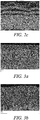
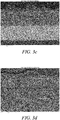
- Figures 3c and 3d show the second embodiment sample after CMAS attack. It can be seen that the second embodiment thermal barrier coating has even greater improved resistance to CMAS attack.
- the numerous branched outer ceramic layers have significantly limited CMAS penetration to the inner columnar ceramic layer such that the column grain structure and inter-columnar gaps remain.
- Figure 3d shows the dissolution and sintering of the outer ceramic layers which leads to a dense protective barrier limiting further penetration of molten CMAS.
Landscapes
- Chemical & Material Sciences (AREA)
- Engineering & Computer Science (AREA)
- Mechanical Engineering (AREA)
- Materials Engineering (AREA)
- Organic Chemistry (AREA)
- Metallurgy (AREA)
- Chemical Kinetics & Catalysis (AREA)
- Inorganic Chemistry (AREA)
- Physics & Mathematics (AREA)
- Plasma & Fusion (AREA)
- Ceramic Engineering (AREA)
- General Engineering & Computer Science (AREA)
- Other Surface Treatments For Metallic Materials (AREA)
- Turbine Rotor Nozzle Sealing (AREA)
- Coating By Spraying Or Casting (AREA)
Abstract
The present disclosure relates to a thermal barrier coating for coating a substrate. The thermal barrier coating may comprise an inner ceramic layer (e.g. 7YSZ) having a columnar grain structure and a first outer ceramic layer (e.g. 7YSZ) having a branched grain structure. The thermal barrier coating further comprises a nucleation layer (which may comprise alumina or tantala), interposed between the inner ceramic layer and the first outer layer. The layers can be deposited by PVD using substantially contact deposition parameters because the nucleation layer induces branching in the first outer ceramic layer.
Description
- The present disclosure relates to thermal barrier coatings for protection of components against environmental contaminants. The present disclosure also relates to components (e.g. gas turbine engine components) with such coatings and a method for preparing such coated components.
- Gas turbine engines comprise a number of components (e.g. blades, vanes, nozzles and shrouds in the combustor or turbine engine sections) that are provided with a thermal barrier coating barrier to limit the exposure of the component to the operating temperature of the gas turbine engine.
- The thermal barrier coating usually comprises a ceramic material, such as a chemically (metal oxide) stabilized zirconia, for example, yttria-stabilized zirconia, scandia-stabilized zirconia, calcia-stabilized zirconia, and magnesia-stabilized zirconia. The surface of the component typically comprises a bond coat layer for adhesion to the ceramic material deposited thereon.
- Thermal barrier coatings may be deposited by physical vapor deposition techniques. Typically, these thermal barrier coatings comprise a columnar ceramic structure; this columnar grain structure allows these thermal barrier coatings to tolerate strains occurring during thermal cycling and to reduce stresses due to the differences between the coefficient of thermal expansion of the component and the thermal barrier coating.
- At the high temperatures within the combustor/turbine sections of an operating gas turbine engine, environmental contaminants (in particular oxides of calcium, magnesium, aluminum, silicon), can form liquid or molten calcium-magnesium-aluminum-silicon-oxide compositions (hereinafter referred to as CMAS compositions). These CMAS compositions can dissolve the thermal barrier coating or can infiltrate its inter-columnar gaps. Upon cooling within the columnar grain structure, the infiltrated CMAS solidifies and reduces the coating strain/stress tolerance. This can result in cracking and ultimately delamination of the thermal barrier coating material. This, in turn leads to the loss of the thermal protection provided to the component.
- In order to try and protect the columnar grain structure of the ceramic layer and thus preserve the thermal stress/strain tolerance of the thermal barrier coating, it is known to deposit a second (high dopant) ceramic layer (e.g. gadolinia stabilized zirconia/hafnia) onto a (low dopant) columnar ceramic layer (e.g. yttria stabilized zirconia/hafnia), the second layer having a branched or feathered structure. The branched grain structure results in a more tortuous porous structure that is more resistant to penetration of the CMAS composition and thus protects the underlying columnar ceramic layer.
- One problem with this known combination of an inner columnar layer and outer branched layer is that markedly different deposition parameters are required to achieve the branched grain structure than those needed for the deposition of the columnar layer. This makes the process of forming the dual layer thermal barrier coating difficult to implement within current industrial scale coating equipment.
- Other attempts to limit CMAS composition corrosion of ceramic thermal barrier coatings have involved co-depositing a non-alumina ceramic and up to 50wt% alumina as an outer layer in a thermal barrier coating. The alumina reacts with the CMAS compositions in a crystallization reaction limiting penetration of the CMAS down any pores/channels in the ceramic layer. However, the porous structure of the alumina/non-alumina ceramic layer does not itself present any physical barrier to penetration should any unreacted CMAS compositions remain.
- It would be desirable to provide a thermal barrier coating that ameliorates the problems of the known thermal barrier coatings.
- According to a first aspect there is provided a thermal barrier coating for coating a substrate, the thermal barrier coating comprising:
- an inner ceramic layer having a columnar grain structure; and
- a first outer ceramic layer having a branched grain structure,
- wherein the thermal barrier coating further comprises a nucleation layer interposed between the inner ceramic layer and the first outer layer.
- It has been found that depositing a nucleation layer on an inner columnar ceramic layer, causes branching of a subsequently deposited outer ceramic layer without the need for the markedly different deposition parameters that are typically required to deposit columnar ceramic and branched ceramic materials. This results in a considerably simpler process for forming the coating which, in turn reduces manufacturing time and costs for the component.
- In some embodiments, the nucleation layer comprises an oxide or silicate having a different crystal structure to the inner and/or outer ceramic layer. For example, if the inner and/or outer ceramic layer comprises a tetragonal crystal structure, the nucleation layer may comprise a hexagonal close packed or orthorhombic crystal structure.
- The nucleation layer may comprise one or more of:
- alumina (Al2O3);
- a rare-earth oxide or silicate (e.g. ytterbium or yttrium silicate or oxide); and/or
- a transition metal oxide (e.g. tantalum pentoxide/tantala(Ta2O5), nickel-chromium oxide or titania (TiO2).
- In preferred embodiments, the nucleation layer comprises alumina or tantala. It may further comprise titania.
- The inner ceramic layer may comprise a zirconia or hafnia or titania, e.g. a stabilised zirconia/hafnia/titania. The stabilised zirconia/hafnia/titania may be stabilised with a rare earth element oxide such as yttria, gadolinia, or scandia, or a combination of rare earth element oxides. Suitable yttria-stabilized zirconia/hafnia/titania can include around 3-10 wt% and more preferably 7-9wt% yttria.
- The inner ceramic layer has a columnar grain structure i.e. it comprises a series of substantially parallel columns extending perpendicularly towards the nucleation layer. The inner ceramic layer further comprises inter-columnar gaps for imparting stress/strain tolerance. The columnar grain structure of a ceramic layer is clearly visible using scanning electron microscopy.
- The first outer ceramic layer may be formed of the same or different ceramic material as the inner ceramic layer. It may comprise a zirconia or hafnia or titania, e.g. a stabilised zirconia/hafnia/titania. The stabilised zirconia/hafnia/titania may be stabilised with up to 80wt% of a rare earth element oxide such as yttria, gadolinia, or scandia, or a combination of rare earth element oxides. Suitable yttria-stabilized zirconia/hafnia/titania can include around 3-10wt% and more preferably 7-9wt% yttria.
- The first outer ceramic layer has a branched grain structure i.e. it comprises branched or feathered grain structure, the branches directed generally away from the nucleation layer. The outer ceramic layer comprises a more tortuous porous structure than that provided by the inter-columnar gaps in the outer ceramic layer. The branched/feathered structure of a ceramic layer is clearly visible using scanning electron microscopy.
- The thermal barrier coating may further comprise a second nucleation layer and a second outer ceramic layer overlying the first nucleation layer and first outer ceramic layer (with the second nucleation layer interposed between the first and second outer ceramic layers). The second nucleation layer will induce further branching in the second outer ceramic layer.
- The thermal barrier coating may comprise at least one further pair of nucleation and outer ceramic layers overlying the second nucleation layer and the second outer ceramic layers. Thus, the thermal barrier coating may comprise an inner columnar ceramic layer and an alternating arrangement of nucleation layers and outer branched ceramic layers.
- There may be greater than 5, e.g. greater than 10, 20 or 30, such as greater than 40, 50 or 60, for example, greater than 70, 80, 90 or 100 nucleation/outer branched ceramic layers.
- The second/further nucleation layer(s) may be the same as the first nucleation layer.
- The second/further outer ceramic layer(s) may be the same as the inner ceramic layer and/or the first outer ceramic layer.
- The inner ceramic layer may have a thickness of between 50-150 microns.
- The nucleation layer may be thinner than the inner ceramic layer.
- The/each nucleation layer may have a thickness of between 0.1 and 5 microns e.g. between 0.2 and 2 microns. The nucleation layers may be of uniform or variable thickness.
- The or each outer ceramic layer may be thinner than the inner ceramic layer. The or each outer layer may be thicker than the nucleation layer. The outer ceramic layers may be of uniform or variable thickness.
- The or each outer ceramic layer may have a thickness of between 0.3 and 10 microns.
- Each of the inner ceramic layer, nucleation layer(s) and outer ceramic layer(s) may have a thickness of between 100-150 microns.
- In the embodiments, the thermal barrier coating further comprises a bonding coat layer on an inner surface of the inner ceramic layer. The bond coat layer may comprise diffused platinum or a metallic alloy e.g. a metallic alloy comprising aluminium, silicon or chromium.
- In a second aspect, there is provided a component comprising a substrate at least partially coated with the thermal barrier coating according to the first aspect.
- The substrate may comprise a metal alloy such as a nickel, cobalt, and/or iron based alloy (e.g. a high temperature superalloy), a refractory metal or an inter-metallic.
- In some embodiments, the metal component is a gas turbine engine component such as a blade, vane nozzle, shroud, liner or deflector.
- In a third aspect, there is provided a method of coating a substrate with a thermal barrier coating, said method comprising:
- depositing an inner layer of ceramic having a columnar grain structure on the substrate;
- depositing a nucleation layer on the inner layer of ceramic; and
- depositing an outer layer of ceramic on the nucleation layer such that the nucleation layer effects nucleation of branching within the outer layer of ceramic.
- The method may comprise depositing a nucleation layer comprising one or more of:
- alumina (Al2O3);
- a rare-earth oxide or silicate (e.g. ytterbium or yttrium silicate or oxide); and/or
- a transition metal oxide (e.g. tantalum pentoxide/tantala(Ta2O5), nickel-chromium oxide or titania (TiO2).
- In preferred embodiments, the method may comprise depositing a nucleation layer comprising alumina or tantala optionally further comprise titania.
- The method may comprise depositing a zirconia or hafnia or titania, e.g. a stabilised zirconia/hafnia/titania as the inner layer of ceramic. The stabilised zirconia/hafnia/titania may be stabilised with a rare earth element oxide such as yttria, gadolinia, or scandia, or a combination of rare earth element oxides. Suitable yttria-stabilized zirconia/hafnia/titania can include around 3-10 wt% and more preferably 7-9wt% yttria.
- The method may comprise depositing a zirconia or hafnia or titania, e.g. a stabilised zirconia/hafnia/titania as the first outer layer of ceramic. The method may comprise depositing zirconia/hafnia/titania stabilised with up to 80 wt% of a rare earth element oxide such as yttria, gadolinia, or scandia, or a combination of rare earth element oxides. Suitable yttria-stabilized zirconia/hafnia/titania can include around 3-10wt% and more preferably 7-9wt% yttria.
- The substrate may be as described for the second aspect.
- In some embodiments, the method further comprises depositing a second nucleation layer on the outer layer of ceramic and depositing a second outer layer of ceramic on the second nucleation layer such that the second nucleation layer effects nucleation of branching within the second outer layer of ceramic.
- In some embodiments, the method may comprise depositing at least one further pair of nucleation and outer ceramic layers overlying the second nucleation layer and the second outer ceramic layers.
- In some embodiments, the method may comprise depositing 5 or more. For example, this may be 10 or more, 20 or more or 30 or more. Furthermore, this could be 40 or more, 50 or more or 60 or more. Alternatively, this could be 70 or more, 80 or more, 90 or more or 100 or more nucleation/outer ceramic layers.
- The second/further outer ceramic layer(s) may be the same as the inner ceramic layer and/or the first outer ceramic layer.
- In some embodiments, the method comprises depositing the layers using physical vapour deposition (PVD) e.g. electron beam-PVD, suspension plasma spraying (SPS), solution precursor plasma spraying (SPPS), plasma spray physical vapour deposition (PS_PVD) or directed vapour deposition (DVD).
- In some embodiments, the method comprises depositing the layers using substantially constant deposition parameters (e.g. power, temperature, chamber pressure). In some embodiments, the method comprises depositing the layers using a substantially constant component (part) temperature. In some embodiments, the method comprises depositing the layers using a substantially constant chamber pressure. In some embodiments, the method comprises depositing the layers using a substantially constant vapour incidence angle. In some embodiments, the method comprises depositing the layers on a rotating component using a substantially constant rotational speed.
- The method may further comprise an abrasive surface treatment step (e.g. grit or sandblasting or peening) on the substrate prior to deposition of the layers.
- The method may further comprise deposition of a bond coat layer on the substrate prior to deposition of the inner layer of ceramic. The bond coat layer may be as described above for the first aspect. The bond coat layer may be formed by electroplating and then optionally by heat treating. For example, the bond coat layer may be formed by electroplating and heat-treating platinum. In other embodiments, the bond coat layer may be applied by a combination of electroplating platinum and deposition of aluminium by chemical vapour deposition optionally with intermediate heat-treatment operations.
- The skilled person will appreciate that except where mutually exclusive, a feature or parameter described in relation to any one of the above aspects may be applied to any other aspect. Furthermore, except where mutually exclusive, any feature or parameter described herein may be applied to any aspect and/or combined with any other feature or parameter described herein.
- Embodiments will now be described by way of example only, with reference to the Figures, in which:
-
Figure 1a is an SEM photograph of a single layer 7YSZ coating prior to CMAS attack; -
Figure 1b is an SEM photograph of the single layer 7YSZ coating after CMAS attack; -
Figure 2a is an SEM photograph of a first embodiment of a coating having an inner columnar ceramic layer and multiple nucleation and outer branched ceramic layers prior to CMAS attack; -
Figure 2b is an enlarged section ofFigure 2a ; -
Figure 2c is an SEM photograph of the first embodiment after CMAS attack; -
Figure 3a is an SEM photograph of a second embodiment of a coating having an inner columnar ceramic layer and multiple nucleation and outer branched ceramic layers prior to CMAS attack; -
Figure 3b is an enlarged section ofFigure 3a ; -
Figure 3c is an SEM photograph of the second embodiment after CMAS attack; and -
Figure 3d is an enlarged section ofFigure 3c . - First, a comparative sample was prepared using a metallic nickel-based substrate which was treated by grit-blasting using #220 brown alumina and subsequently coated with an aluminide bond coat layer.
- A ceramic layer having a columnar grain structure, a thickness of 135 microns and comprising 7-9wt% yttria-stabilised zirconia (7YSZ) was deposited on the substrate using electron beam-physical vapour deposition (EB-PVD) at a temperature of 980 °C, a power of 36 kW and a chamber pressure of 6x10⁻³ mbar.
- The resulting columnar ceramic layer is shown in
Figure 1a . The columnar grain structure is clearly visible with the ceramic layer comprising multiple parallel columns extending away perpendicularly to the surface of the substrate, the columns spaced by inter-columnar gaps. These gaps provide for thermal stress/strain tolerances by allowing independent movement of the columns. - Next, the CMAS resistance of the sample was tested by using an air spray gun to deposit an even film (having a loading of 15 mg/cm2) of a CMAS suspension comprising 35 mol% CaO, 10mol% MgO, 7 mol%Al2O3 and 48mol% SiO2 in deionized water onto the ceramic layer. The sample was then exposed to a temperature of 1300 °C in a furnace for 30 minutes to induce CMAS attack. The sample was then allowed to cool before being sectioned for assessment.
-
Figure 1b shows the sample after CMAS attack. It can be seen that the sample has poor resistance to CMAS attack. The CMAS has penetrated the ceramic layer through the inter-columnar gaps to partially dissolve the ceramic material leading to degradation of the columnar grain structure as a result of sintering and merging of the columns. The degradation of the columns (and the resulting reduction in the inter-columnar gaps) reduces the stress/strain tolerance of the ceramic layer leading to premature failure and delamination of the layer. - Next, a sample having a thermal barrier coating according to a first embodiment comprising an inner columnar ceramic (7YSZ) layer and three nucleation layers comprising alumina alternating with three outer branched ceramic (7YSZ) layers was prepared and is shown in
Figure 2a . - The first embodiment sample was prepared using a metallic nickel-based substrate which was treated by grit-blasting using #220 brown alumina and subsequently coated with a bond coat layer. The EB-PVD coater was set up with 7YSZ and alumina ingot materials and the deposition parameters (e.g. temperature, chamber pressure, power) were fixed. The temperature was fixed between 930-980 °C, the power at 36 kW and the chamber pressure at 6x10⁻³ mbar.
- The 7YSZ ingot material was selected and using to deposit an inner ceramic layer having a columnar grain structure and a thickness of 57 microns. Next, without altering the deposition parameters, the ingot material selection was changed to alumina (using a moving hearth or jumping beam technology) and a first nucleation layer comprising alumina and having a thickness of 2 microns was deposited on the inner ceramic layer. The ingot material was then switched back (again without altering the deposition parameters) and a first outer layer of ceramic (7YSZ) having a thickness of 8 microns was deposited on top of the nucleation layer. The switching of ingot materials was repeated (retaining otherwise constant deposition parameters) to form a second alumina nucleation layer (2 micron thickness), second outer ceramic layer (9 micron thickness), third alumina nucleation layer (0.5 micron thickness) and third outer ceramic layer (5 micron thickness). Accordingly, the entire thermal barrier coating was formed using substantially constant deposition parameters.
- It can be seen in
Figure 2a that the inner ceramic layer has a columnar grain structure with inter-columnar gaps. The enlarged section shown inFigure 2b clearly shows the feathering within the outer ceramic layers caused as a result of side branching induced by the alumina nucleation layers. - Next, a sample having a thermal barrier coating according to a second embodiment comprising an inner columnar ceramic (7YSZ) layer (68 micron thickness) and approximately 100 nucleation layers comprising alumina (0.2 micron thickness) alternating with approximately 100 outer branched ceramic (7YSZ) layers (0.4 micron thickness) was prepared in the same manner as the first embodiment sample and is shown in
Figure 3a. Figure 3b clearly shows the alternating alumina and branched/feathered outer ceramic layers. - Next, the CMAS resistance of the first and second embodiment thermal barrier coatings was tested by using an air spray gun to deposit an even film (having a loading of 15 mg/cm2) of a CMAS suspension comprising 35 mol% CaO, 10mol% MgO, 7 mol% Al2O3 and 48mol% SiO2 in deionized water onto the outermost ceramic layer. The first and second embodiment samples were then exposed to a temperature of 1300 °C in a furnace for 30 minutes to induce CMAS attack. The samples were allowed to cool before being sectioned for assessment.
-
Figure 2c shows the first embodiment sample after CMAS attack. It can be seen that the first embodiment thermal barrier coating has improved resistance to CMAS attack. The branched outer ceramic layers have undergone partial dissolution by the penetrating molten CMAS but the branching has limited CMAS penetration to the inner columnar ceramic layer such that the column grain structure and inter-columnar gaps remain. -
Figures 3c and 3d show the second embodiment sample after CMAS attack. It can be seen that the second embodiment thermal barrier coating has even greater improved resistance to CMAS attack. The numerous branched outer ceramic layers have significantly limited CMAS penetration to the inner columnar ceramic layer such that the column grain structure and inter-columnar gaps remain.Figure 3d shows the dissolution and sintering of the outer ceramic layers which leads to a dense protective barrier limiting further penetration of molten CMAS. - Protection of the columnar inner ceramic provides a thermal barrier coating which maintains its stress/strain tolerance after CMAS attack.
- It will be understood that the disclosure is not limited to the embodiments above-described and various modifications and improvements can be made without departing from the concepts described herein. Except where mutually exclusive, any of the features may be employed separately or in combination with any other features and the disclosure extends to and includes all combinations and sub-combinations of one or more features described herein.
Claims (15)
- A thermal barrier coating for coating a substrate, the thermal barrier coating comprising:at least an inner ceramic layer having a columnar grain structure; andat least a first outer ceramic layer having a branched grain structure,wherein the thermal barrier coating further comprises a nucleation layer interposed between the inner ceramic layer and the first outer layer.
- The thermal barrier coating according to claim 1 wherein the nucleation layer comprises one or more of: alumina (Al2O3); a rare-earth oxide or silicate; and/or a transition metal oxide.
- The thermal barrier coating of claim 2 wherein the nucleation layer comprises alumina or tantala.
- The thermal barrier coating of any one of claims 1 to 3 comprising a second nucleation layer and a second outer ceramic layer having a branched grain structure overlying the first nucleation layer and first outer ceramic layer with the second nucleation layer interposed between the first and second outer ceramic layers.
- The thermal barrier coating of any one of claims 1 to 4 comprising greater than 50 pairs of alternating nucleation layers and outer ceramic layers having a branched grain structure.
- The thermal barrier coating of any one of claims 1 to 5 wherein the inner ceramic layer and the/each outer ceramic layer is independently selected from a zirconia or hafnia or titania.
- The thermal barrier coating according to claim 6 wherein the inner ceramic layer and the/each outer ceramic layer is independently selected from a zirconia, hafnia, titania stabilised with one or more rare earth element oxide.
- The thermal barrier coating according to claim 7 wherein the inner ceramic layer and the/each outer ceramic layer is yttria-stablised zirconia or hafnia.
- A component comprising a substrate at least partially coated with the thermal barrier coating according to any one of claims 1 to 8.
- The component according to claim 9 wherein the component is a gas turbine engine component comprising a blade, vane nozzle, shroud, liner or deflector.
- A method of coating a substrate with a thermal barrier coating, said method comprising:depositing an inner layer of ceramic having a columnar grain structure on the substrate;depositing a nucleation layer on the inner layer of ceramic; anddepositing an outer layer of ceramic on the nucleation layer such that the nucleation layer effects nucleation of branching within the outer layer of ceramic.
- The method of claim 11 further comprising depositing a second nucleation layer on the outer layer of ceramic and depositing a second outer layer of ceramic on the second nucleation layer such that the second nucleation layer effects nucleation of branching within the second outer layer of ceramic.
- The method of claim 11 or 12 further comprising depositing 50 or more pairs of alternating nucleation and outer ceramic layers overlying the first/second nucleation layer and the first/second outer ceramic layer.
- The method according to any one of claims 11 to 13 comprising depositing the layers using physical vapour deposition (PVD).
- The method according to any one of claims 11 to 14 wherein the ceramic layers comprise yttria-stablised zirconia or hafnia and the nucleation layer(s) comprise(s) alumina or tantala.
Applications Claiming Priority (1)
| Application Number | Priority Date | Filing Date | Title |
|---|---|---|---|
| GBGB1918278.1A GB201918278D0 (en) | 2019-12-12 | 2019-12-12 | Thermal barrier coating |
Publications (1)
| Publication Number | Publication Date |
|---|---|
| EP3835451A1 true EP3835451A1 (en) | 2021-06-16 |
Family
ID=69186658
Family Applications (1)
| Application Number | Title | Priority Date | Filing Date |
|---|---|---|---|
| EP20208358.0A Withdrawn EP3835451A1 (en) | 2019-12-12 | 2020-11-18 | Thermal barrier coating |
Country Status (3)
| Country | Link |
|---|---|
| US (1) | US20210254221A1 (en) |
| EP (1) | EP3835451A1 (en) |
| GB (1) | GB201918278D0 (en) |
Cited By (1)
| Publication number | Priority date | Publication date | Assignee | Title |
|---|---|---|---|---|
| FR3146909A1 (en) * | 2023-03-21 | 2024-09-27 | Safran | Part coated with a protective structure against calcium and magnesium aluminosilicates |
Families Citing this family (1)
| Publication number | Priority date | Publication date | Assignee | Title |
|---|---|---|---|---|
| CN116120062B (en) * | 2022-08-24 | 2024-04-12 | 昆明理工大学 | A high temperature resistant defective Y(YxTa1-x)O4-x oxygen barrier/thermal barrier ceramic integrated material and preparation method thereof |
Citations (5)
| Publication number | Priority date | Publication date | Assignee | Title |
|---|---|---|---|---|
| US6183884B1 (en) * | 1998-01-13 | 2001-02-06 | Rolls-Royce Plc | Metallic article having a thermal barrier coating and a method of application thereof |
| GB2383338A (en) * | 2001-12-21 | 2003-06-25 | Howmet Res Corp | Ceramic thermal barrier containing angled columnar grains |
| US20130095256A1 (en) * | 2011-10-17 | 2013-04-18 | Derek Hass | Impact and erosion resistant thermal and environmental barrier coatings |
| EP3159430A1 (en) * | 2015-10-12 | 2017-04-26 | United Technologies Corporation | Multi-layered coating with columnar microstructure and branched columnar microstructure |
| EP3159429A1 (en) * | 2015-10-12 | 2017-04-26 | United Technologies Corporation | Multi-layered coating with columnar microstructure and branched columnar microstructure |
-
2019
- 2019-12-12 GB GBGB1918278.1A patent/GB201918278D0/en not_active Ceased
-
2020
- 2020-11-18 EP EP20208358.0A patent/EP3835451A1/en not_active Withdrawn
- 2020-11-19 US US16/952,233 patent/US20210254221A1/en not_active Abandoned
Patent Citations (5)
| Publication number | Priority date | Publication date | Assignee | Title |
|---|---|---|---|---|
| US6183884B1 (en) * | 1998-01-13 | 2001-02-06 | Rolls-Royce Plc | Metallic article having a thermal barrier coating and a method of application thereof |
| GB2383338A (en) * | 2001-12-21 | 2003-06-25 | Howmet Res Corp | Ceramic thermal barrier containing angled columnar grains |
| US20130095256A1 (en) * | 2011-10-17 | 2013-04-18 | Derek Hass | Impact and erosion resistant thermal and environmental barrier coatings |
| EP3159430A1 (en) * | 2015-10-12 | 2017-04-26 | United Technologies Corporation | Multi-layered coating with columnar microstructure and branched columnar microstructure |
| EP3159429A1 (en) * | 2015-10-12 | 2017-04-26 | United Technologies Corporation | Multi-layered coating with columnar microstructure and branched columnar microstructure |
Cited By (1)
| Publication number | Priority date | Publication date | Assignee | Title |
|---|---|---|---|---|
| FR3146909A1 (en) * | 2023-03-21 | 2024-09-27 | Safran | Part coated with a protective structure against calcium and magnesium aluminosilicates |
Also Published As
| Publication number | Publication date |
|---|---|
| GB201918278D0 (en) | 2020-01-29 |
| US20210254221A1 (en) | 2021-08-19 |
Similar Documents
| Publication | Publication Date | Title |
|---|---|---|
| EP2208805B1 (en) | Strain tolerant thermal barrier coating system | |
| US4916022A (en) | Titania doped ceramic thermal barrier coatings | |
| JP5067775B2 (en) | Process for producing corrosion-resistant EBC bond coats and the like for silicon-containing substrates | |
| EP1428902B1 (en) | Thermal barrier coating protected by infiltrated alumina and method for preparing same | |
| EP1218564B1 (en) | In-situ formation of multiphase air plasma sprayed barrier coatings for turbine components | |
| US5993980A (en) | Protective coating for protecting a component from corrosion, oxidation and excessive thermal stress, process for producing the coating and gas turbine component | |
| EP1995350B1 (en) | High temperature component with thermal barrier coating | |
| US6730413B2 (en) | Thermal barrier coating | |
| EP1418252B1 (en) | Multiphase thermal barrier coatings for very high temperature applications | |
| EP1820879B1 (en) | Durable reactive thermal barrier coatings | |
| EP1889949B1 (en) | Sodium containing thermal barrier coating | |
| EP1400611A1 (en) | Thermal barrier coating material comprising rare earth oxides | |
| JP6386740B2 (en) | Ceramic powder and method therefor | |
| JP2007015913A (en) | Process for producing bond coats of silicon-containing substrates for EBC and the like | |
| JP2003201586A (en) | Thermal barrier coating system, and material | |
| US20160010471A1 (en) | Coating systems and methods therefor | |
| US6168875B1 (en) | Coatings for turbine components | |
| EP3835451A1 (en) | Thermal barrier coating | |
| US6663983B1 (en) | Thermal barrier coating with improved strength and fracture toughness | |
| US6756082B1 (en) | Thermal barrier coating resistant to sintering | |
| JP2000178764A (en) | Improved diffusion aluminide bonding coat for thermal barrier coating system and its preparation | |
| JP2005350771A (en) | Nickel aluminide coating with improved oxide stability region | |
| WO2002027066A2 (en) | Thermal barrier coating resistant to sintering | |
| US20070128458A1 (en) | Protection of metallic surfaces against thermally-inducted wrinkling (rumpling) |
Legal Events
| Date | Code | Title | Description |
|---|---|---|---|
| PUAI | Public reference made under article 153(3) epc to a published international application that has entered the european phase |
Free format text: ORIGINAL CODE: 0009012 |
|
| STAA | Information on the status of an ep patent application or granted ep patent |
Free format text: STATUS: THE APPLICATION HAS BEEN PUBLISHED |
|
| AK | Designated contracting states |
Kind code of ref document: A1 Designated state(s): AL AT BE BG CH CY CZ DE DK EE ES FI FR GB GR HR HU IE IS IT LI LT LU LV MC MK MT NL NO PL PT RO RS SE SI SK SM TR |
|
| STAA | Information on the status of an ep patent application or granted ep patent |
Free format text: STATUS: THE APPLICATION IS DEEMED TO BE WITHDRAWN |
|
| 18D | Application deemed to be withdrawn |
Effective date: 20211217 |