EP3835208A1 - Bootstrap air cycle with vapor power turbine - Google Patents
Bootstrap air cycle with vapor power turbine Download PDFInfo
- Publication number
- EP3835208A1 EP3835208A1 EP20208711.0A EP20208711A EP3835208A1 EP 3835208 A1 EP3835208 A1 EP 3835208A1 EP 20208711 A EP20208711 A EP 20208711A EP 3835208 A1 EP3835208 A1 EP 3835208A1
- Authority
- EP
- European Patent Office
- Prior art keywords
- flow path
- fluid flow
- working fluid
- turbine
- pressurized medium
- Prior art date
- Legal status (The legal status is an assumption and is not a legal conclusion. Google has not performed a legal analysis and makes no representation as to the accuracy of the status listed.)
- Granted
Links
Images


Classifications
-
- B—PERFORMING OPERATIONS; TRANSPORTING
- B64—AIRCRAFT; AVIATION; COSMONAUTICS
- B64D—EQUIPMENT FOR FITTING IN OR TO AIRCRAFT; FLIGHT SUITS; PARACHUTES; ARRANGEMENT OR MOUNTING OF POWER PLANTS OR PROPULSION TRANSMISSIONS IN AIRCRAFT
- B64D13/00—Arrangements or adaptations of air-treatment apparatus for aircraft crew or passengers, or freight space
- B64D13/06—Arrangements or adaptations of air-treatment apparatus for aircraft crew or passengers, or freight space the air being conditioned
-
- F—MECHANICAL ENGINEERING; LIGHTING; HEATING; WEAPONS; BLASTING
- F25—REFRIGERATION OR COOLING; COMBINED HEATING AND REFRIGERATION SYSTEMS; HEAT PUMP SYSTEMS; MANUFACTURE OR STORAGE OF ICE; LIQUEFACTION SOLIDIFICATION OF GASES
- F25B—REFRIGERATION MACHINES, PLANTS OR SYSTEMS; COMBINED HEATING AND REFRIGERATION SYSTEMS; HEAT PUMP SYSTEMS
- F25B9/00—Compression machines, plants or systems, in which the refrigerant is air or other gas of low boiling point
- F25B9/002—Compression machines, plants or systems, in which the refrigerant is air or other gas of low boiling point characterised by the refrigerant
- F25B9/004—Compression machines, plants or systems, in which the refrigerant is air or other gas of low boiling point characterised by the refrigerant the refrigerant being air
-
- B—PERFORMING OPERATIONS; TRANSPORTING
- B64—AIRCRAFT; AVIATION; COSMONAUTICS
- B64D—EQUIPMENT FOR FITTING IN OR TO AIRCRAFT; FLIGHT SUITS; PARACHUTES; ARRANGEMENT OR MOUNTING OF POWER PLANTS OR PROPULSION TRANSMISSIONS IN AIRCRAFT
- B64D13/00—Arrangements or adaptations of air-treatment apparatus for aircraft crew or passengers, or freight space
- B64D13/06—Arrangements or adaptations of air-treatment apparatus for aircraft crew or passengers, or freight space the air being conditioned
- B64D2013/0603—Environmental Control Systems
- B64D2013/0618—Environmental Control Systems with arrangements for reducing or managing bleed air, using another air source, e.g. ram air
-
- B—PERFORMING OPERATIONS; TRANSPORTING
- B64—AIRCRAFT; AVIATION; COSMONAUTICS
- B64D—EQUIPMENT FOR FITTING IN OR TO AIRCRAFT; FLIGHT SUITS; PARACHUTES; ARRANGEMENT OR MOUNTING OF POWER PLANTS OR PROPULSION TRANSMISSIONS IN AIRCRAFT
- B64D13/00—Arrangements or adaptations of air-treatment apparatus for aircraft crew or passengers, or freight space
- B64D13/06—Arrangements or adaptations of air-treatment apparatus for aircraft crew or passengers, or freight space the air being conditioned
- B64D2013/0603—Environmental Control Systems
- B64D2013/064—Environmental Control Systems comprising more than one system, e.g. dual systems
-
- B—PERFORMING OPERATIONS; TRANSPORTING
- B64—AIRCRAFT; AVIATION; COSMONAUTICS
- B64D—EQUIPMENT FOR FITTING IN OR TO AIRCRAFT; FLIGHT SUITS; PARACHUTES; ARRANGEMENT OR MOUNTING OF POWER PLANTS OR PROPULSION TRANSMISSIONS IN AIRCRAFT
- B64D13/00—Arrangements or adaptations of air-treatment apparatus for aircraft crew or passengers, or freight space
- B64D13/06—Arrangements or adaptations of air-treatment apparatus for aircraft crew or passengers, or freight space the air being conditioned
- B64D2013/0603—Environmental Control Systems
- B64D2013/0648—Environmental Control Systems with energy recovery means, e.g. using turbines
-
- B—PERFORMING OPERATIONS; TRANSPORTING
- B64—AIRCRAFT; AVIATION; COSMONAUTICS
- B64D—EQUIPMENT FOR FITTING IN OR TO AIRCRAFT; FLIGHT SUITS; PARACHUTES; ARRANGEMENT OR MOUNTING OF POWER PLANTS OR PROPULSION TRANSMISSIONS IN AIRCRAFT
- B64D13/00—Arrangements or adaptations of air-treatment apparatus for aircraft crew or passengers, or freight space
- B64D13/06—Arrangements or adaptations of air-treatment apparatus for aircraft crew or passengers, or freight space the air being conditioned
- B64D2013/0603—Environmental Control Systems
- B64D2013/0674—Environmental Control Systems comprising liquid subsystems
-
- B—PERFORMING OPERATIONS; TRANSPORTING
- B64—AIRCRAFT; AVIATION; COSMONAUTICS
- B64D—EQUIPMENT FOR FITTING IN OR TO AIRCRAFT; FLIGHT SUITS; PARACHUTES; ARRANGEMENT OR MOUNTING OF POWER PLANTS OR PROPULSION TRANSMISSIONS IN AIRCRAFT
- B64D13/00—Arrangements or adaptations of air-treatment apparatus for aircraft crew or passengers, or freight space
- B64D13/06—Arrangements or adaptations of air-treatment apparatus for aircraft crew or passengers, or freight space the air being conditioned
- B64D2013/0603—Environmental Control Systems
- B64D2013/0688—Environmental Control Systems with means for recirculating cabin air
-
- F—MECHANICAL ENGINEERING; LIGHTING; HEATING; WEAPONS; BLASTING
- F05—INDEXING SCHEMES RELATING TO ENGINES OR PUMPS IN VARIOUS SUBCLASSES OF CLASSES F01-F04
- F05B—INDEXING SCHEME RELATING TO WIND, SPRING, WEIGHT, INERTIA OR LIKE MOTORS, TO MACHINES OR ENGINES FOR LIQUIDS COVERED BY SUBCLASSES F03B, F03D AND F03G
- F05B2220/00—Application
- F05B2220/50—Application for auxiliary power units (APU's)
Definitions
- bleed air provides the air needed to power an air cycle machine (ACM) of the ECS, remove aircraft heat loads, and provide air for other functions.
- air cycle machines provide a means of conditioning air provided to an aircraft passenger cabin and/or other aircraft systems.
- Air cycle machines operate by expanding compressed bleed air across a turbine in which bleed air imparts potential and/or kinetic energy to turbine blades to cause rotation of the turbine shaft.
- bleed air extracted from a compressor section of the gas turbine engine has elevated pressure and temperature relative to an upstream compressor stage and ambient air conditions, a heat exchanger is used to reduce the bleed air temperature prior to the air cycle machine.
- the waste heat is discharged to the ambient environment without preforming any work and thereby reduces an overall efficiency of the gas turbine engine.
- the system includes a ram air duct, the condenser being arranged within the ram air duct such that the cooling medium is ram air.
- the air cycle machine includes a fan and the fan is driven by extracting work from the working fluid within the turbine.
- system is at least one pack of an environmental control system of an aircraft.
- the pressurized medium A from the pressurized medium source 22 is provided to a primary heat exchanger 24 arranged within a ram air duct 26 such that the pressurized medium A is in a heat exchange relationship with a cooling medium, such as ram or ambient air.
- a cooling medium such as ram or ambient air.
- the resulting cooler pressurized medium A is communicated through a passage 28 to a compressor 30.
- the pressurized medium A is compressed to a high pressure.
- the compressor 30 may be located on a common shaft 32 with a first turbine 34 and a fan 36. Together the fan 36, compressor, 30, and first turbine 34 define an air cycle machine (ACM).
- ACM air cycle machine
Landscapes
- Engineering & Computer Science (AREA)
- Health & Medical Sciences (AREA)
- General Health & Medical Sciences (AREA)
- Pulmonology (AREA)
- Aviation & Aerospace Engineering (AREA)
- Physics & Mathematics (AREA)
- Mechanical Engineering (AREA)
- Thermal Sciences (AREA)
- General Engineering & Computer Science (AREA)
- Engine Equipment That Uses Special Cycles (AREA)
Abstract
Description
- This present disclosure relates generally to gas turbine engine and, more particularly, to a system powered by bleed air extracted from the gas turbine engine.
- Gas turbine engines operate by compressing a primary air flow stream received through an inlet, combusting an air-fuel mixture within a combustor, and directing the exhaust stream of the combustion process to perform work on a turbine before discharging the exhaust. Some gas turbine engines include auxiliary flow paths that extract a portion of the primary air flow passing through a compressor section of the gas turbine engine to form a bleed air stream. Bleed air can be used to perform work ancillary to the primary combustion process of the gas turbine engine, among other functions.
- For example, in a typical environmental control system (ECS), bleed air provides the air needed to power an air cycle machine (ACM) of the ECS, remove aircraft heat loads, and provide air for other functions. In particular, air cycle machines provide a means of conditioning air provided to an aircraft passenger cabin and/or other aircraft systems. Air cycle machines operate by expanding compressed bleed air across a turbine in which bleed air imparts potential and/or kinetic energy to turbine blades to cause rotation of the turbine shaft. Because bleed air extracted from a compressor section of the gas turbine engine has elevated pressure and temperature relative to an upstream compressor stage and ambient air conditions, a heat exchanger is used to reduce the bleed air temperature prior to the air cycle machine. Typically, the waste heat is discharged to the ambient environment without preforming any work and thereby reduces an overall efficiency of the gas turbine engine.
- Because increasing gas turbine engine efficiency continues to be a goal for aircraft engine manufacturers, a need exists to utilize the waste bleed air heat to perform work for auxiliary engine systems and/or other aircraft systems.
- According to one embodiment, a system includes a first fluid flow path configured to condition a pressurized medium and deliver the pressurized medium to one or more loads. The first fluid flow path including an air cycle machine. A second fluid flow path is configured to circulate a working fluid. The second fluid flow path includes a heat exchanger thermally coupled to the first fluid flow path. Within the heat exchanger, heat extracted from the pressurized medium is transferred to the working fluid. The second fluid flow path additionally includes a turbine operably coupled to the air cycle machine, a condenser, and a pump operable to circulate the working fluid through at least a portion of the second fluid flow path. The turbine is rotationally driven by expanding the working fluid across the turbine.
- In addition to one or more of the features described above, or as an alternative, in further embodiments the first fluid flow path is an open-loop path and the second fluid flow path is a closed-loop path.
- In addition to one or more of the features described above, or as an alternative, in further embodiments the working fluid is configured to flow through the heat exchanger, the turbine, the condenser, and the pump sequentially.
- In addition to one or more of the features described above, or as an alternative, in further embodiments the air cycle machine includes a compressor and another turbine operably coupled by a shaft, the turbine of the second fluid flow path being mounted to the shaft.
- In addition to one or more of the features described above, or as an alternative, in further embodiments the air cycle machine further comprises a fan driven by the shaft.
- In addition to one or more of the features described above, or as an alternative, in further embodiments working fluid within the condenser is cooled from a gaseous phase to a liquid phase via a heat exchange relationship with a cooling medium.
- In addition to one or more of the features described above, or as an alternative, in further embodiments the system includes a ram air duct, the condenser being arranged within the ram air duct such that the cooling medium is ram air.
- In addition to one or more of the features described above, or as an alternative, in further embodiments the first fluid flow path includes a second heat exchanger arranged within the ram air duct, the second heat exchanger being located downstream from the condenser relative to a flow of the cooling medium.
- In addition to one or more of the features described above, or as an alternative, in further embodiments working fluid within the condenser is cooled from a gaseous phase to a liquid phase via a heat exchange relationship with a the pressurized medium.
- According to another embodiment, a method includes directing a pressurized medium through a first fluid flow path including an air cycle machine, circulating a working fluid through a second fluid flow path, transferring heat from the pressurized medium to the working fluid at a heat exchanger thermally coupling the first fluid flow path and the second fluid flow path, extracting work from the working fluid within a turbine, and driving one or more rotatable components of the air cycle machine in response to extracting work from the working fluid within the turbine.
- In addition to one or more of the features described above, or as an alternative, in further embodiments directing the pressurized medium through the first fluid flow path further comprises extracting a pressurized medium from a pressurized medium source, conditioning the pressurized medium, and delivering conditioned pressurized medium to one or more loads.
- In addition to one or more of the features described above, or as an alternative, in further embodiments circulating a working fluid through a second fluid flow path further comprises circulating working fluid through the heat exchanger, a turbine, a condenser, and a pump sequentially.
- In addition to one or more of the features described above, or as an alternative, in further embodiments the working fluid circulates through a second fluid flow path via the pump.
- In addition to one or more of the features described above, or as an alternative, in further embodiments the air cycle machine includes a compressor and the compressor is driven by extracting work from the working fluid within the turbine.
- In addition to one or more of the features described above, or as an alternative, in further embodiments the air cycle machine includes a fan and the fan is driven by extracting work from the working fluid within the turbine.
- In addition to one or more of the features described above, or as an alternative, in further embodiments the first fluid flow path is an open-loop path and the second fluid flow path is a closed-loop path.
- In addition to one or more of the features described above, or as an alternative, in further embodiments the pressurized medium is bleed air.
- In addition to one or more of the features described above, or as an alternative, in further embodiments the working fluid is one of refrigerant, water, ammonia, and carbon dioxide.
- In addition to one or more of the features described above, or as an alternative, in further embodiments the system is at least one pack of an environmental control system of an aircraft.
- The subject matter, which is regarded as the invention, is particularly pointed out and distinctly claimed in the claims at the conclusion of the specification. The foregoing and other features, and advantages of the invention are apparent from the following detailed description taken in conjunction with the accompanying drawings in which:
-
FIG. 1 is a schematic diagram of an example of a pack of an environmental control system; -
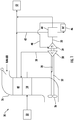
FIG. 2 is a schematic diagram of a portion of a pack of an environmental control system according to an embodiment; and -
FIG. 3 is another schematic diagram of a portion of a pack of an environmental control system according to an embodiment. - A detailed description of one or more embodiments of the disclosed apparatus and method are presented herein by way of exemplification and not limitation with reference to the FIGS.
- Referring now to
FIG. 1 , an example of apack 20 of an environmental control system (ECS) of an aircraft is illustrated. As shown, thepack 20 defines a first fluid flow path of a pressurized medium A, such as air for example, received from a pressurizedmedium source 22. Within the first fluid flow path, the pressurized medium is conditioned to be supplied to one or more loads of the aircraft. Although asingle pack 20 is illustrated, an ECS including any number ofECS packs 20 configured to supply a conditioned air to one or more loads of the aircraft is also within the scope of the disclosure. In one embodiment, the pressurized medium A is bleed air. As used herein, the term "bleed air" includes pressurized air originating from or being "bled" from, an engine or auxiliary power unit of the aircraft. It shall be understood that one or more of the temperature, humidity, and pressure of the bleed air may vary based upon the compressor stage and revolutions per minute of the engine or auxiliary power unit from which the air is drawn. For example, bleed air may be drawn from either a low pressure compressor spool or a high pressure compressor spool of an engine, and bleed air drawn from the low pressure compressor spool will have a relatively lower pressure than bleed air drawn from the high pressure compressor spool. - In the illustrated, non-limiting embodiment, the pressurized medium A from the pressurized
medium source 22 is provided to aprimary heat exchanger 24 arranged within aram air duct 26 such that the pressurized medium A is in a heat exchange relationship with a cooling medium, such as ram or ambient air. After the pressurized medium A is cooled in theprimary heat exchanger 24, the resulting cooler pressurized medium A is communicated through apassage 28 to acompressor 30. Within thecompressor 30, the pressurized medium A is compressed to a high pressure. Thecompressor 30 may be located on acommon shaft 32 with afirst turbine 34 and afan 36. Together thefan 36, compressor, 30, andfirst turbine 34 define an air cycle machine (ACM). - Compressed medium exits the
compressor 30 through apassage 38 and is provided to asecondary heat exchanger 40 configured to further cool the pressurized medium A within thesecondary heat exchanger 40 with a ram air or ambient air flow. As shown, thesecondary heat exchanger 40 is also arranged within theram air duct 26. Compressed, cooled pressurized medium A including water vapor exits from thesecondary heat exchanger 40 and flows through aduct 42 to acondenser 44. Thecondenser 44 is configured to further cool the pressurized medium A by condensing and separating the water into awater extractor 46. Dehumidified pressurized medium A exits thewater extractor 46 and is provided, through apassage 48, to afirst turbine 34. The pressurized medium A is expanded and water vapor in the pressurized medium A is further condensed through thefirst turbine 34 of the ACM. The cooled pressurized medium A flows through apassage 50 back to thecondenser 44, where the pressurized medium A is heated to a relatively warmed temperature, and is then supplied to the loads (illustrated schematically at 52) of the aircraft, such as to the cabin for example. Thepack 20 and the first fluid flow path defined by thepack 20 illustrated and described herein is intended as an example only. It should be understood that a first fluid flow path including additional components or another configuration is also within the scope of the disclosure. - In a typical pack of an environmental control system (ECS) of a vehicle, as shown in
FIG. 1 , at least one heat exchanger is arranged upstream from an air cycle machine relative to a flow of pressurized medium. Within the heat exchanger, such as theprimary heat exchanger 24 for example, waste heat from the pressurized medium A is rejected to a ram air circuit. The ram air flow passes through theprimary heat exchanger 24 and receives the heat rejected from the pressurized medium A before being discharged to the ambient environment. - In an embodiment, the waste heat that is rejected from the pressurized medium A can be utilized to improve the efficiency of the ECS by adapting the
pack 20 of the ECS to include a closed loop configured as a Rankine cycle. A Rankine cycle uses a working fluid to convert heat into mechanical work while the working fluid undergoes a phase change. - With reference now to
FIG. 2 , a simplified schematic diagram of a portion of a pack 120 of an ECS is illustrated. As previously described with respect toFIG. 1 , the ECS pack 120 includes a first fluid flow path that receives a pressurized medium A from a pressurized medium source 122 and delivers a conditioned form of the pressurized medium A to one or more loads 152. As previously described, the first flow path of the pack 120 includes an air cycle machine, identified at 160, having one or more components configured to receive the pressurized medium A. As shown, theair cycle machine 160 includes acompressor 130 and aturbine 134. Thecompressor 130 is configured to receive pressurized medium, and imparts work to the pressurized medium A, thereby increasing a static pressure and/or temperature of the pressurized medium A. Theturbine 134 includes a rotatable impeller (not shown) having a blade geometry configured to extract kinetic energy and/or potential energy from the pressurized medium A. Theturbine 134 is arranged downstream from thecompressor 130 relative to a flow of the pressurized medium A. - In the illustrated embodiment of
FIG. 2 , the pack 120 of the ECS additionally includes a second, closed loop flow path, identified at 162, arranged in a heat exchange relationship with the first fluid flow path. A working fluid R circulates through the secondfluid flow path 162 to form a Rankine cycle. Examples of suitable working fluids R include, but are not limited to refrigerant, water, ammonia, and carbon dioxide. - In the illustrated, non-limiting embodiment, the second
fluid flow path 162 includes aheat exchanger 124, aturbine 164, acondenser 144 and apump 166 arranged sequentially in series relative to a direction of flow of the working fluid R. Afirst conduit 168 connects an outlet of theheat exchanger 124 to an inlet of theturbine 164 and asecond conduit 170 fluidly couples an outlet of theturbine 164 to an inlet of thecondenser 144. Athird conduit 172 connects the outlet of thecondenser 144 to an inlet of thepump 166 and afourth conduit 174 fluidly couples an outlet of thepump 166 to the inlet of theheat exchanger 124. It should be understood that the illustrated second, closed loop flow path is intended as an example only and that a closed loop flow path including additional or other components is also within the scope of the disclosure. - In an embodiment, the
heat exchanger 124 is the primary heat exchanger disposed within the first fluid flow path. However, theheat exchanger 124 has been positioned at a location remote from theram air duct 126. Accordingly, the pressurized medium A within theheat exchanger 124 is cooled via the working fluid R rather than by the ram air. Accordingly, the first fluid flow path and the second fluid flow path are thermally coupled at theheat exchanger 124. Theheat exchanger 124 can have any conventional design that places a first medium, such as bleed air for example, within open-loop path in a heat exchange relationship with the working fluid circulating within the closed-loop path. Becauseheat exchanger 124 is configured to vaporize or boil the working fluid R, the flowrate per unit area of heat transferred from pressurized medium A to the working fluid R, or heat flux, is greater than a threshold heat flux necessary to convert working fluid R from liquid phase at heat exchanger inlet to a gaseous phase at heat exchanger outlet. Furthermore, the minimum design heat flux exceeds the threshold heat flux by a margin sufficient to account for a range of ambient conditions and engine operating conditions such that conduits contain primarily gaseous working fluid for a range of ambient conditions and engine operating conditions. -
Turbine 164 is adapted to extract potential energy (i.e., energy derived from working fluid static pressure), kinetic energy (i.e., energy derived from working fluid dynamic pressure or fluid velocity), or a combination of potential and kinetic energy. Extracting energy from the gaseous working fluid R involves providing blade geometry (not shown) to interact with gaseous working fluid R such that gaseous working fluid imparts rotation to theturbine 164. Due to the extraction of energy, working fluid R output from theturbine 164 has at least one of: an outlet pressure that is less than an inlet pressure, an outlet velocity that is less than an inlet velocity, and c) an outlet pressure and velocity that are less than an inlet pressure and velocity, respectively. - The
condenser 144 arranged within the second closed loop fluid flow path may be the same condenser or alternatively, a different condenser than identified within the first fluid flow path. In the illustrated, non-limiting embodiment ofFIG. 2 , thecondenser 144 is positioned within theram air duct 126. Thecondenser 144 can be a heat exchanger having any conventional design that converts gaseous working fluid R into liquid working fluid R by placing the working fluid in a heat exchange relationship with a heat sink. As shown in the FIG., thecondenser 144 places working fluid R in a heat exchange relationship with a cooling medium of the ram air circuit, such as ram air for example. Although thecondenser 144 is illustrated as being arranged upstream from thesecondary heat exchanger 140 relative to the flow of ram air within theram air duct 126, embodiments where thecondenser 144 is arranged downstream from thesecondary heat exchanger 140 are also contemplated herein. - In another embodiment, as best shown in
FIG. 3 , thecondenser 144 may be located external to theram air duct 126. In such embodiments, the condenser may thermally couple the first and second fluid flow loops. As shown, a portion of the pressurized medium A, such as provided to one ormore loads 152, or alternatively, discharged from the one ormore loads 152, such as cabin discharge air for example, is provided to thecondenser 144, before being dumped overboard or delivered to the cabin. In such embodiments, heat is configured to transfer from the working fluid R to the pressurized medium A within thecondenser 144. - The
pump 166 can be a mechanically-driven or an electrically-driven pump configured to act on and impart work to working fluid R received through a pump inlet. Due to pressure losses associated with circulating working fluid through closed-loop fluid flow path, the work imparted by pump to the working fluid R causes a pressure of working fluid R at the pump outlet to be greater than a pressure of working fluid R at the pump inlet by an amount sufficient to overcome pressure losses at a design flow rate of working fluid through closed-loop. - Within the second
fluid flow path 162, the thermal energy extracted from the pressurized medium A, is utilized to rotationally drive theturbine 164 to convert the thermal energy into mechanical work. This work can be used to increase the efficiency of the pack 120 by rotationally coupling theturbine 164 to another component. In the illustrated, non-limiting embodiment, theturbine 164 is formed as a portion of theair cycle machine 160. Accordingly, theturbine 164 is operably coupled to thecompressor 130,turbine 134, andfan 136 via theshaft 132. By mounting theturbine 164 of the secondfluid flow path 162 to theshaft 132 of theair cycle machine 160, the work extracted within theturbine 164 can be used to rotate theshaft 132, thereby driving thecompressor 130 and/or thefan 136. Although the secondfluid flow path 162 is illustrated as being fluidly coupled to the first fluid flow path defined by a single pack 120 of an environmental control system, it should be understood that in embodiments where an environmental control system includes multiple packs 120, a single secondfluid flow path 162 may be used for multiple packs 120, each pack 120 may be associated with its own secondfluid flow path 162, or alternatively, multiple secondfluid flow paths 162 that share one or more components may be associated with the plurality of packs 120. - The term "about" is intended to include the degree of error associated with measurement of the particular quantity based upon the equipment available at the time of filing the application.
- The terminology used herein is for the purpose of describing particular embodiments only and is not intended to be limiting of the present disclosure. As used herein, the singular forms "a", "an" and "the" are intended to include the plural forms as well, unless the context clearly indicates otherwise. It will be further understood that the terms "comprises" and/or "comprising," when used in this specification, specify the presence of stated features, integers, steps, operations, elements, and/or components, but do not preclude the presence or addition of one or more other features, integers, steps, operations, element components, and/or groups thereof.
- While the present disclosure has been described with reference to an exemplary embodiment or embodiments, it will be understood by those skilled in the art that various changes may be made and equivalents may be substituted for elements thereof without departing from the scope of the present disclosure. In addition, many modifications may be made to adapt a particular situation or material to the teachings of the present disclosure without departing from the essential scope thereof. Therefore, it is intended that the present disclosure not be limited to the particular embodiment disclosed as the best mode contemplated for carrying out this present disclosure, but that the present disclosure will include all embodiments falling within the scope of the claims.
Claims (15)
- A system comprising:a first fluid flow path configured to condition a pressurized medium and deliver the pressurized medium to one or more loads (152), the first fluid flow path including an air cycle machine (160);a second fluid flow path (162) configured to circulate a working fluid, the second fluid flow path including:a heat exchanger (124) thermally coupled to the first fluid flow path, wherein within the heat exchanger, heat extracted from the pressurized medium is transferred to the working fluid;a turbine (164) rotationally driven by expanding the working fluid across the turbine, wherein the turbine is operably coupled to the air cycle machine;a condenser (144); anda pump (166) operable to circulate the working fluid through at least a portion of the second fluid flow path.
- The system of claim 1, wherein the first fluid flow path is an open-loop path and the second fluid flow path is a closed-loop path.
- The system of claim 1 or 2, wherein the working fluid is configured to flow through the heat exchanger, the turbine, the condenser, and the pump sequentially.
- The system of any preceding claim, wherein the air cycle machine includes a compressor (130) and another turbine (134) operably coupled by a shaft (132), the turbine of the second fluid flow path being mounted to the shaft; and preferably
wherein the air cycle machine further comprises a fan (136) driven by the shaft. - The system of any preceding claim, wherein working fluid within the condenser is cooled from a gaseous phase to a liquid phase via a heat exchange relationship with a cooling medium; and preferably
wherein the system includes a ram air duct (126), the condenser being arranged within the ram air duct such that the cooling medium is ram air; and/or
wherein the first fluid flow path includes a second heat exchanger (140) arranged within the ram air duct, the second heat exchanger being located downstream from the condenser relative to a flow of the cooling medium. - The system of any preceding claim, wherein working fluid within the condenser is cooled from a gaseous phase to a liquid phase via a heat exchange relationship with a the pressurized medium.
- The system of any preceding claim, wherein the pressurized medium is bleed air.
- A method comprising:directing a pressurized medium through a first fluid flow path including an air cycle machine;circulating a working fluid through a second fluid flow path;transferring heat from the pressurized medium to the working fluid at a heat exchanger thermally coupling the first fluid flow path and the second fluid flow path;extracting work from the working fluid within a turbine; anddriving one or more rotatable components of the air cycle machine in response to extracting work from the working fluid within the turbine.
- The method of claim 8, wherein directing the pressurized medium through the first fluid flow path further comprises:extracting a pressurized medium from a pressurized medium source;conditioning the pressurized medium; anddelivering conditioned pressurized medium to one or more loads.
- The method of claim 8 or 9, wherein circulating a working fluid through a second fluid flow path further comprises:circulating working fluid through the heat exchanger, a turbine, a condenser, and a pump sequentially; and preferablywherein the working fluid circulates through a second fluid flow path via the pump.
- The method of any of claims 8-10, wherein the air cycle machine includes a compressor and the compressor is driven by extracting work from the working fluid within the turbine.
- The method of any of claims 8-11, wherein the air cycle machine includes a fan and the fan is driven by extracting work from the working fluid within the turbine.
- The method of any of claims 8-12, wherein the first fluid flow path is an open-loop path and the second fluid flow path is a closed-loop path.
- The method of any of claims 8-13, wherein the pressurized medium is bleed air.
- The method of any of claims 8-14, wherein the working fluid is one of refrigerant, water, ammonia, and carbon dioxide; and/or
wherein the system is at least one pack of an environmental control system of an aircraft.
Applications Claiming Priority (1)
| Application Number | Priority Date | Filing Date | Title |
|---|---|---|---|
| US16/707,089 US11465756B2 (en) | 2019-12-09 | 2019-12-09 | Bootstrap air cycle with vapor power turbine |
Publications (2)
| Publication Number | Publication Date |
|---|---|
| EP3835208A1 true EP3835208A1 (en) | 2021-06-16 |
| EP3835208B1 EP3835208B1 (en) | 2024-07-24 |
Family
ID=73497659
Family Applications (1)
| Application Number | Title | Priority Date | Filing Date |
|---|---|---|---|
| EP20208711.0A Active EP3835208B1 (en) | 2019-12-09 | 2020-11-19 | Bootstrap air cycle with vapor power turbine |
Country Status (2)
| Country | Link |
|---|---|
| US (1) | US11465756B2 (en) |
| EP (1) | EP3835208B1 (en) |
Cited By (1)
| Publication number | Priority date | Publication date | Assignee | Title |
|---|---|---|---|---|
| EP4265521A1 (en) * | 2022-04-20 | 2023-10-25 | Hamilton Sundstrand Corporation | Environmental control system with air powered pump |
Families Citing this family (3)
| Publication number | Priority date | Publication date | Assignee | Title |
|---|---|---|---|---|
| US12291337B2 (en) | 2022-02-18 | 2025-05-06 | Rtx Corporation | Aircraft hybrid cooling system |
| US11913377B2 (en) | 2022-02-18 | 2024-02-27 | Rtx Corporation | Environmental control systems |
| US11988418B2 (en) * | 2022-09-14 | 2024-05-21 | Hamilton Sundstrand Corporation | Vapor compression cycle with direct pumped two-phase cooling |
Citations (3)
| Publication number | Priority date | Publication date | Assignee | Title |
|---|---|---|---|---|
| WO1999002401A1 (en) * | 1997-07-11 | 1999-01-21 | Alliedsignal Inc. | Air cycle environmental control system with vapor cycle system assisted condensation |
| WO2012022758A1 (en) * | 2010-08-19 | 2012-02-23 | Airbus Operations Gmbh | Aircraft air conditioning system comprising a separate refrigeration cycle |
| US20170057641A1 (en) * | 2015-08-31 | 2017-03-02 | Honeywell International Inc. | Integrated air and vapor cycle cooling system |
Family Cites Families (6)
| Publication number | Priority date | Publication date | Assignee | Title |
|---|---|---|---|---|
| US7334422B2 (en) * | 2005-11-29 | 2008-02-26 | Hamilton Sundstrand Corporation | Cabin air conditioning system with liquid cooling for power electronics |
| US7987683B2 (en) | 2006-02-20 | 2011-08-02 | Hamilton Sundstrand Corporation | Expendable turbine driven compression cycle cooling system |
| US9874379B2 (en) | 2014-07-09 | 2018-01-23 | Hamilton Sundstrand Corporation | Expendable driven heat pump cycles |
| US10288548B2 (en) | 2015-04-17 | 2019-05-14 | Hamilton Sundstrand Corporation | Wavelet-based analysis for fouling diagnosis of an aircraft heat exchanger |
| US11427331B2 (en) * | 2017-04-13 | 2022-08-30 | Hamilton Sundstrand Corporation | Fresh air and recirculation air mixing optimization |
| US10544705B2 (en) | 2018-03-16 | 2020-01-28 | Hamilton Sundstrand Corporation | Rankine cycle powered by bleed heat |
-
2019
- 2019-12-09 US US16/707,089 patent/US11465756B2/en active Active
-
2020
- 2020-11-19 EP EP20208711.0A patent/EP3835208B1/en active Active
Patent Citations (3)
| Publication number | Priority date | Publication date | Assignee | Title |
|---|---|---|---|---|
| WO1999002401A1 (en) * | 1997-07-11 | 1999-01-21 | Alliedsignal Inc. | Air cycle environmental control system with vapor cycle system assisted condensation |
| WO2012022758A1 (en) * | 2010-08-19 | 2012-02-23 | Airbus Operations Gmbh | Aircraft air conditioning system comprising a separate refrigeration cycle |
| US20170057641A1 (en) * | 2015-08-31 | 2017-03-02 | Honeywell International Inc. | Integrated air and vapor cycle cooling system |
Cited By (1)
| Publication number | Priority date | Publication date | Assignee | Title |
|---|---|---|---|---|
| EP4265521A1 (en) * | 2022-04-20 | 2023-10-25 | Hamilton Sundstrand Corporation | Environmental control system with air powered pump |
Also Published As
| Publication number | Publication date |
|---|---|
| US11465756B2 (en) | 2022-10-11 |
| EP3835208B1 (en) | 2024-07-24 |
| US20210171204A1 (en) | 2021-06-10 |
Similar Documents
| Publication | Publication Date | Title |
|---|---|---|
| EP3835208B1 (en) | Bootstrap air cycle with vapor power turbine | |
| EP3480113B1 (en) | Regenerative system ecoecs | |
| US11053010B2 (en) | Aircraft environmental control system | |
| US7665304B2 (en) | Rankine cycle device having multiple turbo-generators | |
| US11851192B2 (en) | Aircraft environmental control system | |
| US11408647B2 (en) | Enhanced thermally-driven ejector cycles | |
| US20160231031A1 (en) | Environmental control system utilizing cabin air to drive a power turbine of an air cycle machine and utilizing multiple mix points for recirculation air in accordance with pressure mode | |
| EP3470337B1 (en) | Supplemental pack driven by bleed air and cabin air | |
| US10544705B2 (en) | Rankine cycle powered by bleed heat | |
| CN106064671B (en) | Environmental control system for mixing cabin discharge air with bleed air during a cycle | |
| EP4292937B1 (en) | Ram air turbine powered cabin air compressor | |
| US10543924B2 (en) | Environmental control system utilizing multiple mix points for recirculation air in accordance with pressure mode | |
| EP3677508A1 (en) | Concentric turbine condensing cycle | |
| US12162607B2 (en) | Environmental control system for supersonic commercial aircraft | |
| JP2004245193A (en) | Air cycle air conditioner for aircraft | |
| US20240410625A1 (en) | Regeneration using liquid loop of environmental control system | |
| EP4282761B1 (en) | Vapor compression system for aerospace applications | |
| EP4265521B1 (en) | Environmental control system with air powered pump | |
| EP3235730B1 (en) | Environmental control system utilizing cabin air to drive a power turbine of an air cycle machine and utilizing multiple mix points for recirculation air in accordance with pressure mode | |
| EP4269245A1 (en) | Environmental control system and vapor control system water separation overlap | |
| US20250313066A1 (en) | Environmental control system with mixed bleed and ambient pack | |
| US20250304264A1 (en) | Environmental control system using architecture with turbines in series | |
| CN119900644B (en) | Turbine engine including air turbine starter and bleed air circuit | |
| EP4299444A1 (en) | Split regeneration environmental control system | |
| US20250282482A1 (en) | Environmental control system using architecture with dual entry turbine |
Legal Events
| Date | Code | Title | Description |
|---|---|---|---|
| PUAI | Public reference made under article 153(3) epc to a published international application that has entered the european phase |
Free format text: ORIGINAL CODE: 0009012 |
|
| STAA | Information on the status of an ep patent application or granted ep patent |
Free format text: STATUS: THE APPLICATION HAS BEEN PUBLISHED |
|
| AK | Designated contracting states |
Kind code of ref document: A1 Designated state(s): AL AT BE BG CH CY CZ DE DK EE ES FI FR GB GR HR HU IE IS IT LI LT LU LV MC MK MT NL NO PL PT RO RS SE SI SK SM TR |
|
| STAA | Information on the status of an ep patent application or granted ep patent |
Free format text: STATUS: REQUEST FOR EXAMINATION WAS MADE |
|
| 17P | Request for examination filed |
Effective date: 20211214 |
|
| RBV | Designated contracting states (corrected) |
Designated state(s): AL AT BE BG CH CY CZ DE DK EE ES FI FR GB GR HR HU IE IS IT LI LT LU LV MC MK MT NL NO PL PT RO RS SE SI SK SM TR |
|
| STAA | Information on the status of an ep patent application or granted ep patent |
Free format text: STATUS: EXAMINATION IS IN PROGRESS |
|
| 17Q | First examination report despatched |
Effective date: 20221116 |
|
| GRAP | Despatch of communication of intention to grant a patent |
Free format text: ORIGINAL CODE: EPIDOSNIGR1 |
|
| STAA | Information on the status of an ep patent application or granted ep patent |
Free format text: STATUS: GRANT OF PATENT IS INTENDED |
|
| INTG | Intention to grant announced |
Effective date: 20240226 |
|
| GRAS | Grant fee paid |
Free format text: ORIGINAL CODE: EPIDOSNIGR3 |
|
| GRAA | (expected) grant |
Free format text: ORIGINAL CODE: 0009210 |
|
| STAA | Information on the status of an ep patent application or granted ep patent |
Free format text: STATUS: THE PATENT HAS BEEN GRANTED |
|
| AK | Designated contracting states |
Kind code of ref document: B1 Designated state(s): AL AT BE BG CH CY CZ DE DK EE ES FI FR GB GR HR HU IE IS IT LI LT LU LV MC MK MT NL NO PL PT RO RS SE SI SK SM TR |
|
| REG | Reference to a national code |
Ref country code: GB Ref legal event code: FG4D |
|
| REG | Reference to a national code |
Ref country code: CH Ref legal event code: EP |
|
| REG | Reference to a national code |
Ref country code: DE Ref legal event code: R096 Ref document number: 602020034396 Country of ref document: DE |
|
| REG | Reference to a national code |
Ref country code: IE Ref legal event code: FG4D |
|
| REG | Reference to a national code |
Ref country code: LT Ref legal event code: MG9D |
|
| REG | Reference to a national code |
Ref country code: NL Ref legal event code: MP Effective date: 20240724 |
|
| PG25 | Lapsed in a contracting state [announced via postgrant information from national office to epo] |
Ref country code: PT Free format text: LAPSE BECAUSE OF FAILURE TO SUBMIT A TRANSLATION OF THE DESCRIPTION OR TO PAY THE FEE WITHIN THE PRESCRIBED TIME-LIMIT Effective date: 20241125 |
|
| REG | Reference to a national code |
Ref country code: AT Ref legal event code: MK05 Ref document number: 1706096 Country of ref document: AT Kind code of ref document: T Effective date: 20240724 |
|
| PG25 | Lapsed in a contracting state [announced via postgrant information from national office to epo] |
Ref country code: NL Free format text: LAPSE BECAUSE OF FAILURE TO SUBMIT A TRANSLATION OF THE DESCRIPTION OR TO PAY THE FEE WITHIN THE PRESCRIBED TIME-LIMIT Effective date: 20240724 |
|
| PG25 | Lapsed in a contracting state [announced via postgrant information from national office to epo] |
Ref country code: PT Free format text: LAPSE BECAUSE OF FAILURE TO SUBMIT A TRANSLATION OF THE DESCRIPTION OR TO PAY THE FEE WITHIN THE PRESCRIBED TIME-LIMIT Effective date: 20241125 Ref country code: NL Free format text: LAPSE BECAUSE OF FAILURE TO SUBMIT A TRANSLATION OF THE DESCRIPTION OR TO PAY THE FEE WITHIN THE PRESCRIBED TIME-LIMIT Effective date: 20240724 |
|
| PG25 | Lapsed in a contracting state [announced via postgrant information from national office to epo] |
Ref country code: NO Free format text: LAPSE BECAUSE OF FAILURE TO SUBMIT A TRANSLATION OF THE DESCRIPTION OR TO PAY THE FEE WITHIN THE PRESCRIBED TIME-LIMIT Effective date: 20241024 |
|
| PG25 | Lapsed in a contracting state [announced via postgrant information from national office to epo] |
Ref country code: GR Free format text: LAPSE BECAUSE OF FAILURE TO SUBMIT A TRANSLATION OF THE DESCRIPTION OR TO PAY THE FEE WITHIN THE PRESCRIBED TIME-LIMIT Effective date: 20241025 Ref country code: FI Free format text: LAPSE BECAUSE OF FAILURE TO SUBMIT A TRANSLATION OF THE DESCRIPTION OR TO PAY THE FEE WITHIN THE PRESCRIBED TIME-LIMIT Effective date: 20240724 Ref country code: PL Free format text: LAPSE BECAUSE OF FAILURE TO SUBMIT A TRANSLATION OF THE DESCRIPTION OR TO PAY THE FEE WITHIN THE PRESCRIBED TIME-LIMIT Effective date: 20240724 |
|
| PG25 | Lapsed in a contracting state [announced via postgrant information from national office to epo] |
Ref country code: BG Free format text: LAPSE BECAUSE OF FAILURE TO SUBMIT A TRANSLATION OF THE DESCRIPTION OR TO PAY THE FEE WITHIN THE PRESCRIBED TIME-LIMIT Effective date: 20240724 |
|
| PG25 | Lapsed in a contracting state [announced via postgrant information from national office to epo] |
Ref country code: LV Free format text: LAPSE BECAUSE OF FAILURE TO SUBMIT A TRANSLATION OF THE DESCRIPTION OR TO PAY THE FEE WITHIN THE PRESCRIBED TIME-LIMIT Effective date: 20240724 |
|
| PG25 | Lapsed in a contracting state [announced via postgrant information from national office to epo] |
Ref country code: AT Free format text: LAPSE BECAUSE OF FAILURE TO SUBMIT A TRANSLATION OF THE DESCRIPTION OR TO PAY THE FEE WITHIN THE PRESCRIBED TIME-LIMIT Effective date: 20240724 Ref country code: IS Free format text: LAPSE BECAUSE OF FAILURE TO SUBMIT A TRANSLATION OF THE DESCRIPTION OR TO PAY THE FEE WITHIN THE PRESCRIBED TIME-LIMIT Effective date: 20241124 |
|
| PG25 | Lapsed in a contracting state [announced via postgrant information from national office to epo] |
Ref country code: HR Free format text: LAPSE BECAUSE OF FAILURE TO SUBMIT A TRANSLATION OF THE DESCRIPTION OR TO PAY THE FEE WITHIN THE PRESCRIBED TIME-LIMIT Effective date: 20240724 |
|
| PG25 | Lapsed in a contracting state [announced via postgrant information from national office to epo] |
Ref country code: RS Free format text: LAPSE BECAUSE OF FAILURE TO SUBMIT A TRANSLATION OF THE DESCRIPTION OR TO PAY THE FEE WITHIN THE PRESCRIBED TIME-LIMIT Effective date: 20241024 Ref country code: ES Free format text: LAPSE BECAUSE OF FAILURE TO SUBMIT A TRANSLATION OF THE DESCRIPTION OR TO PAY THE FEE WITHIN THE PRESCRIBED TIME-LIMIT Effective date: 20240724 |
|
| PG25 | Lapsed in a contracting state [announced via postgrant information from national office to epo] |
Ref country code: RS Free format text: LAPSE BECAUSE OF FAILURE TO SUBMIT A TRANSLATION OF THE DESCRIPTION OR TO PAY THE FEE WITHIN THE PRESCRIBED TIME-LIMIT Effective date: 20241024 Ref country code: PL Free format text: LAPSE BECAUSE OF FAILURE TO SUBMIT A TRANSLATION OF THE DESCRIPTION OR TO PAY THE FEE WITHIN THE PRESCRIBED TIME-LIMIT Effective date: 20240724 Ref country code: NO Free format text: LAPSE BECAUSE OF FAILURE TO SUBMIT A TRANSLATION OF THE DESCRIPTION OR TO PAY THE FEE WITHIN THE PRESCRIBED TIME-LIMIT Effective date: 20241024 Ref country code: LV Free format text: LAPSE BECAUSE OF FAILURE TO SUBMIT A TRANSLATION OF THE DESCRIPTION OR TO PAY THE FEE WITHIN THE PRESCRIBED TIME-LIMIT Effective date: 20240724 Ref country code: IS Free format text: LAPSE BECAUSE OF FAILURE TO SUBMIT A TRANSLATION OF THE DESCRIPTION OR TO PAY THE FEE WITHIN THE PRESCRIBED TIME-LIMIT Effective date: 20241124 Ref country code: HR Free format text: LAPSE BECAUSE OF FAILURE TO SUBMIT A TRANSLATION OF THE DESCRIPTION OR TO PAY THE FEE WITHIN THE PRESCRIBED TIME-LIMIT Effective date: 20240724 Ref country code: GR Free format text: LAPSE BECAUSE OF FAILURE TO SUBMIT A TRANSLATION OF THE DESCRIPTION OR TO PAY THE FEE WITHIN THE PRESCRIBED TIME-LIMIT Effective date: 20241025 Ref country code: FI Free format text: LAPSE BECAUSE OF FAILURE TO SUBMIT A TRANSLATION OF THE DESCRIPTION OR TO PAY THE FEE WITHIN THE PRESCRIBED TIME-LIMIT Effective date: 20240724 Ref country code: ES Free format text: LAPSE BECAUSE OF FAILURE TO SUBMIT A TRANSLATION OF THE DESCRIPTION OR TO PAY THE FEE WITHIN THE PRESCRIBED TIME-LIMIT Effective date: 20240724 Ref country code: BG Free format text: LAPSE BECAUSE OF FAILURE TO SUBMIT A TRANSLATION OF THE DESCRIPTION OR TO PAY THE FEE WITHIN THE PRESCRIBED TIME-LIMIT Effective date: 20240724 Ref country code: AT Free format text: LAPSE BECAUSE OF FAILURE TO SUBMIT A TRANSLATION OF THE DESCRIPTION OR TO PAY THE FEE WITHIN THE PRESCRIBED TIME-LIMIT Effective date: 20240724 |
|
| PG25 | Lapsed in a contracting state [announced via postgrant information from national office to epo] |
Ref country code: DK Free format text: LAPSE BECAUSE OF FAILURE TO SUBMIT A TRANSLATION OF THE DESCRIPTION OR TO PAY THE FEE WITHIN THE PRESCRIBED TIME-LIMIT Effective date: 20240724 Ref country code: SM Free format text: LAPSE BECAUSE OF FAILURE TO SUBMIT A TRANSLATION OF THE DESCRIPTION OR TO PAY THE FEE WITHIN THE PRESCRIBED TIME-LIMIT Effective date: 20240724 Ref country code: RO Free format text: LAPSE BECAUSE OF FAILURE TO SUBMIT A TRANSLATION OF THE DESCRIPTION OR TO PAY THE FEE WITHIN THE PRESCRIBED TIME-LIMIT Effective date: 20240724 |
|
| PG25 | Lapsed in a contracting state [announced via postgrant information from national office to epo] |
Ref country code: EE Free format text: LAPSE BECAUSE OF FAILURE TO SUBMIT A TRANSLATION OF THE DESCRIPTION OR TO PAY THE FEE WITHIN THE PRESCRIBED TIME-LIMIT Effective date: 20240724 |
|
| PG25 | Lapsed in a contracting state [announced via postgrant information from national office to epo] |
Ref country code: CZ Free format text: LAPSE BECAUSE OF FAILURE TO SUBMIT A TRANSLATION OF THE DESCRIPTION OR TO PAY THE FEE WITHIN THE PRESCRIBED TIME-LIMIT Effective date: 20240724 |
|
| REG | Reference to a national code |
Ref country code: DE Ref legal event code: R097 Ref document number: 602020034396 Country of ref document: DE |
|
| PG25 | Lapsed in a contracting state [announced via postgrant information from national office to epo] |
Ref country code: IT Free format text: LAPSE BECAUSE OF FAILURE TO SUBMIT A TRANSLATION OF THE DESCRIPTION OR TO PAY THE FEE WITHIN THE PRESCRIBED TIME-LIMIT Effective date: 20240724 Ref country code: SK Free format text: LAPSE BECAUSE OF FAILURE TO SUBMIT A TRANSLATION OF THE DESCRIPTION OR TO PAY THE FEE WITHIN THE PRESCRIBED TIME-LIMIT Effective date: 20240724 |
|
| PLBE | No opposition filed within time limit |
Free format text: ORIGINAL CODE: 0009261 |
|
| STAA | Information on the status of an ep patent application or granted ep patent |
Free format text: STATUS: NO OPPOSITION FILED WITHIN TIME LIMIT |
|
| REG | Reference to a national code |
Ref country code: CH Ref legal event code: PL |
|
| 26N | No opposition filed |
Effective date: 20250425 |
|
| PG25 | Lapsed in a contracting state [announced via postgrant information from national office to epo] |
Ref country code: MC Free format text: LAPSE BECAUSE OF FAILURE TO SUBMIT A TRANSLATION OF THE DESCRIPTION OR TO PAY THE FEE WITHIN THE PRESCRIBED TIME-LIMIT Effective date: 20240724 |
|
| PG25 | Lapsed in a contracting state [announced via postgrant information from national office to epo] |
Ref country code: LU Free format text: LAPSE BECAUSE OF NON-PAYMENT OF DUE FEES Effective date: 20241119 |
|
| REG | Reference to a national code |
Ref country code: CH Ref legal event code: PL |
|
| PG25 | Lapsed in a contracting state [announced via postgrant information from national office to epo] |
Ref country code: CH Free format text: LAPSE BECAUSE OF NON-PAYMENT OF DUE FEES Effective date: 20241130 |
|
| REG | Reference to a national code |
Ref country code: BE Ref legal event code: MM Effective date: 20241130 |
|
| PG25 | Lapsed in a contracting state [announced via postgrant information from national office to epo] |
Ref country code: SE Free format text: LAPSE BECAUSE OF FAILURE TO SUBMIT A TRANSLATION OF THE DESCRIPTION OR TO PAY THE FEE WITHIN THE PRESCRIBED TIME-LIMIT Effective date: 20240724 |
|
| PG25 | Lapsed in a contracting state [announced via postgrant information from national office to epo] |
Ref country code: BE Free format text: LAPSE BECAUSE OF NON-PAYMENT OF DUE FEES Effective date: 20241130 |
|
| PG25 | Lapsed in a contracting state [announced via postgrant information from national office to epo] |
Ref country code: IE Free format text: LAPSE BECAUSE OF NON-PAYMENT OF DUE FEES Effective date: 20241119 |
|
| PGFP | Annual fee paid to national office [announced via postgrant information from national office to epo] |
Ref country code: DE Payment date: 20251022 Year of fee payment: 6 |
|
| PGFP | Annual fee paid to national office [announced via postgrant information from national office to epo] |
Ref country code: GB Payment date: 20251022 Year of fee payment: 6 |
|
| PGFP | Annual fee paid to national office [announced via postgrant information from national office to epo] |
Ref country code: FR Payment date: 20251022 Year of fee payment: 6 |
|
| PG25 | Lapsed in a contracting state [announced via postgrant information from national office to epo] |
Ref country code: HU Free format text: LAPSE BECAUSE OF FAILURE TO SUBMIT A TRANSLATION OF THE DESCRIPTION OR TO PAY THE FEE WITHIN THE PRESCRIBED TIME-LIMIT; INVALID AB INITIO Effective date: 20201119 |
|
| PG25 | Lapsed in a contracting state [announced via postgrant information from national office to epo] |
Ref country code: CY Free format text: LAPSE BECAUSE OF FAILURE TO SUBMIT A TRANSLATION OF THE DESCRIPTION OR TO PAY THE FEE WITHIN THE PRESCRIBED TIME-LIMIT; INVALID AB INITIO Effective date: 20201119 |