EP3835069B1 - Enhanced print defect detection - Google Patents
Enhanced print defect detection Download PDFInfo
- Publication number
- EP3835069B1 EP3835069B1 EP20213007.6A EP20213007A EP3835069B1 EP 3835069 B1 EP3835069 B1 EP 3835069B1 EP 20213007 A EP20213007 A EP 20213007A EP 3835069 B1 EP3835069 B1 EP 3835069B1
- Authority
- EP
- European Patent Office
- Prior art keywords
- defect
- nozzle
- nozzle defect
- data
- Prior art date
- Legal status (The legal status is an assumption and is not a legal conclusion. Google has not performed a legal analysis and makes no representation as to the accuracy of the status listed.)
- Active
Links
Images

Classifications
-
- G—PHYSICS
- G06—COMPUTING OR CALCULATING; COUNTING
- G06T—IMAGE DATA PROCESSING OR GENERATION, IN GENERAL
- G06T7/00—Image analysis
- G06T7/0002—Inspection of images, e.g. flaw detection
- G06T7/0004—Industrial image inspection
- G06T7/001—Industrial image inspection using an image reference approach
-
- B—PERFORMING OPERATIONS; TRANSPORTING
- B41—PRINTING; LINING MACHINES; TYPEWRITERS; STAMPS
- B41J—TYPEWRITERS; SELECTIVE PRINTING MECHANISMS, i.e. MECHANISMS PRINTING OTHERWISE THAN FROM A FORME; CORRECTION OF TYPOGRAPHICAL ERRORS
- B41J2/00—Typewriters or selective printing mechanisms characterised by the printing or marking process for which they are designed
- B41J2/005—Typewriters or selective printing mechanisms characterised by the printing or marking process for which they are designed characterised by bringing liquid or particles selectively into contact with a printing material
- B41J2/01—Ink jet
- B41J2/015—Ink jet characterised by the jet generation process
- B41J2/04—Ink jet characterised by the jet generation process generating single droplets or particles on demand
- B41J2/045—Ink jet characterised by the jet generation process generating single droplets or particles on demand by pressure, e.g. electromechanical transducers
- B41J2/04501—Control methods or devices therefor, e.g. driver circuits, control circuits
- B41J2/0451—Control methods or devices therefor, e.g. driver circuits, control circuits for detecting failure, e.g. clogging, malfunctioning actuator
-
- B—PERFORMING OPERATIONS; TRANSPORTING
- B41—PRINTING; LINING MACHINES; TYPEWRITERS; STAMPS
- B41J—TYPEWRITERS; SELECTIVE PRINTING MECHANISMS, i.e. MECHANISMS PRINTING OTHERWISE THAN FROM A FORME; CORRECTION OF TYPOGRAPHICAL ERRORS
- B41J2/00—Typewriters or selective printing mechanisms characterised by the printing or marking process for which they are designed
- B41J2/005—Typewriters or selective printing mechanisms characterised by the printing or marking process for which they are designed characterised by bringing liquid or particles selectively into contact with a printing material
- B41J2/01—Ink jet
- B41J2/135—Nozzles
- B41J2/165—Prevention or detection of nozzle clogging, e.g. cleaning, capping or moistening for nozzles
- B41J2/16579—Detection means therefor, e.g. for nozzle clogging
-
- B—PERFORMING OPERATIONS; TRANSPORTING
- B41—PRINTING; LINING MACHINES; TYPEWRITERS; STAMPS
- B41J—TYPEWRITERS; SELECTIVE PRINTING MECHANISMS, i.e. MECHANISMS PRINTING OTHERWISE THAN FROM A FORME; CORRECTION OF TYPOGRAPHICAL ERRORS
- B41J2/00—Typewriters or selective printing mechanisms characterised by the printing or marking process for which they are designed
- B41J2/005—Typewriters or selective printing mechanisms characterised by the printing or marking process for which they are designed characterised by bringing liquid or particles selectively into contact with a printing material
- B41J2/01—Ink jet
- B41J2/135—Nozzles
- B41J2/165—Prevention or detection of nozzle clogging, e.g. cleaning, capping or moistening for nozzles
- B41J2/16585—Prevention or detection of nozzle clogging, e.g. cleaning, capping or moistening for nozzles for paper-width or non-reciprocating print heads
-
- B—PERFORMING OPERATIONS; TRANSPORTING
- B41—PRINTING; LINING MACHINES; TYPEWRITERS; STAMPS
- B41J—TYPEWRITERS; SELECTIVE PRINTING MECHANISMS, i.e. MECHANISMS PRINTING OTHERWISE THAN FROM A FORME; CORRECTION OF TYPOGRAPHICAL ERRORS
- B41J2/00—Typewriters or selective printing mechanisms characterised by the printing or marking process for which they are designed
- B41J2/005—Typewriters or selective printing mechanisms characterised by the printing or marking process for which they are designed characterised by bringing liquid or particles selectively into contact with a printing material
- B41J2/01—Ink jet
- B41J2/21—Ink jet for multi-colour printing
- B41J2/2132—Print quality control characterised by dot disposition, e.g. for reducing white stripes or banding
- B41J2/2142—Detection of malfunctioning nozzles
-
- B—PERFORMING OPERATIONS; TRANSPORTING
- B41—PRINTING; LINING MACHINES; TYPEWRITERS; STAMPS
- B41J—TYPEWRITERS; SELECTIVE PRINTING MECHANISMS, i.e. MECHANISMS PRINTING OTHERWISE THAN FROM A FORME; CORRECTION OF TYPOGRAPHICAL ERRORS
- B41J2/00—Typewriters or selective printing mechanisms characterised by the printing or marking process for which they are designed
- B41J2/005—Typewriters or selective printing mechanisms characterised by the printing or marking process for which they are designed characterised by bringing liquid or particles selectively into contact with a printing material
- B41J2/01—Ink jet
- B41J2/21—Ink jet for multi-colour printing
- B41J2/2132—Print quality control characterised by dot disposition, e.g. for reducing white stripes or banding
- B41J2/2146—Print quality control characterised by dot disposition, e.g. for reducing white stripes or banding for line print heads
-
- B—PERFORMING OPERATIONS; TRANSPORTING
- B41—PRINTING; LINING MACHINES; TYPEWRITERS; STAMPS
- B41J—TYPEWRITERS; SELECTIVE PRINTING MECHANISMS, i.e. MECHANISMS PRINTING OTHERWISE THAN FROM A FORME; CORRECTION OF TYPOGRAPHICAL ERRORS
- B41J29/00—Details of, or accessories for, typewriters or selective printing mechanisms not otherwise provided for
- B41J29/38—Drives, motors, controls or automatic cut-off devices for the entire printing mechanism
- B41J29/393—Devices for controlling or analysing the entire machine ; Controlling or analysing mechanical parameters involving printing of test patterns
-
- B—PERFORMING OPERATIONS; TRANSPORTING
- B41—PRINTING; LINING MACHINES; TYPEWRITERS; STAMPS
- B41J—TYPEWRITERS; SELECTIVE PRINTING MECHANISMS, i.e. MECHANISMS PRINTING OTHERWISE THAN FROM A FORME; CORRECTION OF TYPOGRAPHICAL ERRORS
- B41J2/00—Typewriters or selective printing mechanisms characterised by the printing or marking process for which they are designed
- B41J2/005—Typewriters or selective printing mechanisms characterised by the printing or marking process for which they are designed characterised by bringing liquid or particles selectively into contact with a printing material
- B41J2/01—Ink jet
- B41J2/015—Ink jet characterised by the jet generation process
- B41J2/04—Ink jet characterised by the jet generation process generating single droplets or particles on demand
- B41J2/045—Ink jet characterised by the jet generation process generating single droplets or particles on demand by pressure, e.g. electromechanical transducers
- B41J2/04501—Control methods or devices therefor, e.g. driver circuits, control circuits
- B41J2/04586—Control methods or devices therefor, e.g. driver circuits, control circuits controlling heads of a type not covered by groups B41J2/04575 - B41J2/04585, or of an undefined type
-
- B—PERFORMING OPERATIONS; TRANSPORTING
- B41—PRINTING; LINING MACHINES; TYPEWRITERS; STAMPS
- B41J—TYPEWRITERS; SELECTIVE PRINTING MECHANISMS, i.e. MECHANISMS PRINTING OTHERWISE THAN FROM A FORME; CORRECTION OF TYPOGRAPHICAL ERRORS
- B41J29/00—Details of, or accessories for, typewriters or selective printing mechanisms not otherwise provided for
- B41J29/38—Drives, motors, controls or automatic cut-off devices for the entire printing mechanism
- B41J29/393—Devices for controlling or analysing the entire machine ; Controlling or analysing mechanical parameters involving printing of test patterns
- B41J2029/3935—Devices for controlling or analysing the entire machine ; Controlling or analysing mechanical parameters involving printing of test patterns by means of printed test patterns
-
- G—PHYSICS
- G06—COMPUTING OR CALCULATING; COUNTING
- G06T—IMAGE DATA PROCESSING OR GENERATION, IN GENERAL
- G06T2207/00—Indexing scheme for image analysis or image enhancement
- G06T2207/10—Image acquisition modality
- G06T2207/10004—Still image; Photographic image
-
- G—PHYSICS
- G06—COMPUTING OR CALCULATING; COUNTING
- G06T—IMAGE DATA PROCESSING OR GENERATION, IN GENERAL
- G06T2207/00—Indexing scheme for image analysis or image enhancement
- G06T2207/20—Special algorithmic details
- G06T2207/20084—Artificial neural networks [ANN]
-
- G—PHYSICS
- G06—COMPUTING OR CALCULATING; COUNTING
- G06T—IMAGE DATA PROCESSING OR GENERATION, IN GENERAL
- G06T2207/00—Indexing scheme for image analysis or image enhancement
- G06T2207/30—Subject of image; Context of image processing
- G06T2207/30108—Industrial image inspection
-
- G—PHYSICS
- G06—COMPUTING OR CALCULATING; COUNTING
- G06T—IMAGE DATA PROCESSING OR GENERATION, IN GENERAL
- G06T2207/00—Indexing scheme for image analysis or image enhancement
- G06T2207/30—Subject of image; Context of image processing
- G06T2207/30108—Industrial image inspection
- G06T2207/30144—Printing quality
Definitions
- the invention relates to the field of printing, and in particular, to detecting print defects.
- An inkjet production printer is a high-speed printer used for volume printing (e.g., one hundred pages per minute or more), and may include continuous-forms printers that print on a web of print media stored on a large roll. While a continuous-forms inkjet printer operates, the web is quickly passed underneath the nozzles of printheads of the printer, which discharge ink onto the web at intervals to form pixels.
- Print defect identification is typically performed manually by a trained print operator at the beginning of a day or print cycle. However, even if the operator has a lot of experience and training to distinguish among the various types of print defects, human print defect analysis is time consuming and subject to inaccuracies.
- US 2019/0168514 A1 discloses a method of identifying at least one malfunctioning nozzle in a digital printing press including a plurality of nozzles.
- the method includes the procedures of printing a design on a substrate, acquiring at least one image of the printed design and identifying at least one artifact in the acquired image.
- the method further includes the procedure of identifying the malfunctioning nozzle and classifying the at least one malfunctioning nozzle according to at least a portion of a combined pattern.
- Embodiments herein describe enhanced print defect detection.
- a defect detection system of a printer distinguishes between different types of print defects automatically with high precision and speed. Using reference data of previously identified defect types, the defect detection system is able to determine the location and type of defect for individual nozzles of the printer. Types of nozzle defects present in a printhead are determined quickly and accurately, and may be used to inform maintenance decisions for improved efficiency of maintenance procedures performed for the printer.
- FIG. 1 is a diagram of a print system 100 in an illustrative embodiment.
- the print system 100 includes a printer 120 and a defect detection system 150.
- the printer 120 receives a print job, generates rasterized print data for the print job with the print controller 126, and transmits the rasterized print data for the print job to one or more print engines 127-128.
- the print engines 127-128 mark the web 130 of print media (e.g., paper, textile, printable substrate) with ink (e.g., marking material, colorant, etc.) according to the rasterized print data, thus producing printed output.
- print media e.g., paper, textile, printable substrate
- ink e.g., marking material, colorant, etc.
- the print controller 126 instructs the print engines 127-128 to print a test chart 140 based on test chart print data onto web 130 that can be analyzed manually or by the defect detection system 150 for print defects.
- the defect detection system 150 includes an interface 152, a defect controller 154, and one or more imaging device(s) 156.
- the imaging device 156 may comprise a camera, scanner, densitometer, spectrophotometer or other suitable component for acquiring images of printed content.
- the test chart 140 may be printed on the web 130 separately from the print jobs or with the print jobs (e.g. on sections of the web 130 separate from the sections of the web 130 printed with the print jobs).
- the defect controller 154 analyzes the image for jet defects.
- the defect controller 154 may be configured to determine which printheads or nozzles printed the defects based on the location of the defect in the test chart 140.
- the defect detection system 150 and printer 120 may communicate via interfaces 122/152 (e.g., an Ethernet interface, wireless interface, etc.).
- the print controller 126 may transmit a rasterized version of the print data corresponding to test chart 140 to the defect detection system 150 for comparison to an image of the test chart 140 to determine whether there are any discrepancies that indicate printing errors, and the defect detection system 150 may report (e.g., transmit) print defect data to the printer 120 or other systems to inform maintenance procedures.
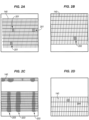
- FIGS. 2A-D illustrate different types of print defects.
- FIG. 2A shows jet-out defects 201 on the test chart 140. Jet-out defects 201 may be caused by a complete blocking of a nozzle (e.g., no ink ejected).
- FIG. 2B shows a deviated jet defect 202 on the test chart 140. Deviated jet defects 202 may be caused by a partial blocking of a nozzle (e.g., ink ejected at least partially to an unintended location on web 130).
- FIG. 2C shows delaminated print head defects 203 on the test chart 140.
- Delaminated head defects 203 may be caused by film on the printhead array peeling off from wear and tear (e.g., a plurality of adjacent nozzles partially blocked or fully blocked).
- FIG. 2D shows an unknown defect 204 on the test chart 140.
- Unknown defects 204 may comprise a category of defects other than that which can be classified into the other print defect categories. Those skilled in the art will appreciate that further nozzle defect types or sub-types may also be defined.
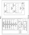
- FIG. 3 is a block diagram of a printer 300 in an illustrative embodiment.
- the printer 300 includes the defect detection system 150 enhanced to determine the type or category of a particular print defect. That is, the defect detection system 150 is configured to categorize print defects as one of a jet-out defect 201, deviated jet defect 202, delaminated head defect 203, or unknown defect 204. By classifying print defects by type, the defect detection system 150 is able to provide operational health data of the printer 300 and facilitate corrective actions to take for efficiently improving print quality. Those skilled in the art will appreciate that defect detection system 150 may be used for other defect type also.
- the printer 300 generally includes a plurality of color planes 330 (e.g., cyan, magenta, yellow, and black) and print engines 332.
- Each print engine 332 may process print data for one or a plurality of color planes 330 and control one or a plurality of printheads 334 based on the print data.
- Each printhead 334 includes an array of nozzles 336 that eject drops of ink 338 for printing.
- the nozzles 336 of each printhead 334 may be assigned to one color plane or divided between a plurality of color planes 330.
- the printheads 334 may be configured physically in the web direction and/or orthogonal to the web direction.
- each printhead 334 may include hundreds of nozzles 336. Due to quantity of ink drops 338 jetted by nozzles 336, the small individual size of the ink drops 338, and similarities in resemblance of different defect types to the human eye, it is difficult and time consuming even for a trained print operator to analyze printed test charts for defect types.
- the defect detection system 150 is enhanced with the defect controller 154 configured to detect a nozzle defect in an image based on a comparison of the image with print data 356, and to determine a type of the nozzle defect based on a comparison of the nozzle defect with the defect reference data.
- the defect controller 154 may take into account data stored in data storage 350, including any combination of current nozzle defect information 351, defect reference data 352, and print system settings 353.
- current nozzle defect information 351 include any combination of nozzle defect type, corresponding nozzle 336 location, corresponding printhead 334 identification, corresponding print engine 332, corresponding printer 300 and/or color plane 330.
- print system settings 353 include a print resolution, selected test pattern type, media type, and/or print engine parameters (e.g., print engine model, print width, paper handling orientation in the print engine, printhead type, ink type, etc.).
- the data storage 350 may also store image data 355 of the test chart 140 captured by the imaging device 156 and/or print data 356 corresponding to the test chart 140. Additionally, the data storage 350 may store printer configuration information 354 that may comprise information that correlates print locations, nozzles 336, printheads 334, print engines 332, color planes 330, and/or ink types (e.g. ink sets or specific ink colors).
- the defect controller 154 may be communicatively coupled with an interface 346 and/or a graphical user interface 348 for receiving user input and/or displaying notifications to the user of the printer 300.
- the processor 342 includes any electronic circuits and/or optical circuits that are able to perform functions.
- a processor may include one or more Central Processing Units (CPU), Graphics Processing Unit (GPU), microprocessors, Digital Signal Processors (DSPs), Application-Specific Integrated Circuits (ASICs), Programmable Logic Devices (PLD), control circuitry, etc.
- CPU Central Processing Unit
- GPU Graphics Processing Unit
- DSP Digital Signal Processor
- ASICs Application-Specific Integrated Circuits
- PLD Programmable Logic Devices
- Some examples of processors include Intel Core processors, Advanced Reduced Instruction Set Computing (RISC) Machines (ARM) processors, etc.
- the memory 344 includes any hardware device that is able to store data.
- the memory 344 may include one or more volatile or non-volatile Dynamic Random Access Memory (DRAM) devices, FLASH devices, volatile or non-volatile Static RAM devices, hard drives, Solid State Disks (SSDs), etc.
- DRAM Dynamic Random Access Memory
- FLASH devices volatile or non-volatile Static RAM devices
- hard drives Solid State Disks (SSDs), etc.
- SSDs Solid State Disks
- non-volatile DRAM and SRAM include battery-backed DRAM and battery-backed SRAM.
- the data storage 350 may similarly be implemented by any combination of memory devices or components.
- defect detection system 150 is shown as incorporated in the printer 300, portions or an entirety of the defect detection system 150 and functions performed thereby may be implemented in a separate system that is near to the printer 300 (e.g. Digital Front End (DFE)) or remotely as a standalone system (e.g., cloud implementation) in communication with the printer 300. Illustrative details of the operation of the defect detection system 150 will be discussed with regard to FIGS. 4-5 .
- DFE Digital Front End
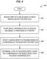
- FIG. 4 is a flowchart illustrating a method 400 of determining a type of print defect in an illustrative embodiment.
- the steps of method 400 are described with reference to the printer 300 and defect detection system 150 of FIG. 3 , but those skilled in the art will appreciate that method 400 may be performed in other systems.
- the steps of the flowcharts described herein are not all inclusive and may include other steps not shown.
- the steps described herein may also be optionally performed or performed in an alternative order.
- the defect controller 154 may receive (e.g., via interface 346) and/or store (e.g., in data storage 350 or a memory) print data (e.g., print data 356), and an image of media printed on with the print data (e.g., image data 355).
- Print data 356 corresponds to the source print data that instructed the printing of test chart 140 and may be in any suitable format for processing such as bitmaps, print description language or print job. In some embodiments, print data 356 for a test chart is incorporated and available within defect reference data 352.
- the defect controller 154 stores (e.g., in data storage 350 or a memory) defect reference data 352 of nozzles 336 belonging to printheads 334 of a printer 300.
- the defect reference data 352 includes rules for the defect controller 154 to use for interpreting the input image and determining defect types.
- Defect reference data 352 includes rules for determining optical density variations beyond a threshold (e.g., missing or unintended ink placement) in image data 355 locations using a template based on test chart 140.
- the defect reference data 352 may be derived from images that exhibit characteristics of a previously defined print defect type. For example, the defect reference data 352 may be based on example print defect images that have been previously categorized either manually or by the defect controller 154.
- Defect reference data 352 may be available for each category of print defects (e.g., a jet-out defect category, deviated defect category, delaminated head defect category, and an unknown category).
- the defect controller 154 detects a nozzle defect in the image based on a comparison of the image with the print data 356. In doing so, the defect controller 154 may analyze image data 355 of the test chart 140 for discrepancies with print data 356 and stores current nozzle defect information 351 in data storage 350. Additionally, the defect controller 154 may correlate defect locations within the test chart 140 or image data 355 with individual nozzles 336, printheads 334, print engines 332, and/or printer 300 that printed a defect based on information of the printer configuration 354 and/or print data 356 stored in data storage 350.
- the defect controller 154 determines a type of the nozzle defect based on a comparison of the nozzle defect image characteristics with the defect reference data 352. For instance, the defect controller 154 may identify a matching or similar pattern in the defect reference data 352 or a common characteristic among defects within the same category, and determine the category to which the nozzle defect belongs based on a match of characteristics in the nozzle defect with that in the pattern or commonality defined in the defect reference data 352.
- the defect controller 154 may determine whether the nozzle defect is one of a jet-out (caused due to complete blocking of a nozzle), a deviated jet (caused by a partial blocking of a nozzle), delaminated head (caused by film on the printhead array peeling off from wear and tear), and unknown (other causes). In some embodiments, the defect controller 154 determines a type of the nozzle defect with look up tables, programmed logic, and/or trained machine learning processor(s). The method 400 provides a benefit over prior techniques by assigning a print defect to a particular classification of inkjet nozzle defects without reliance on trained human operators.
- FIG. 5 is a flowchart illustrating a method 500 of determining a type of print defect in another illustrative embodiment.
- the steps of method 500 are described with reference to the printer 300 and defect detection system 150 of FIG. 3 , but those skilled in the art will appreciate that method 500 may be performed in other systems.
- the steps of the flowcharts described herein are not all inclusive and may include other steps not shown.
- the steps described herein may also be optionally performed or performed in an alternative order.
- the imaging device 156 scans or captures a printed test chart to create a grayscale image (e.g., image data 355). If image data 355 has been stored in data storage 350, then step 502 may be optionally skipped.
- the defect controller 154 aligns the grayscale image with the print data 356.
- the alignment may include adjustment of comparison inputs to account for the edge registration of print engine(s) 332 (e.g., center, left, or right justified) and/or skew. For example, if the printed test master is not printed on a full width of the medium, the defect controller 154 may align the image to left if a first print engine printed the chart, and align the image to the right if a second print engine printed the test chart. Additionally, the defect controller 154 may adjust image data 355 for stretching/shrinkage in the printed medium, and may apply a position correction that is varied for each printhead to better align the grayscale image to the print data 356 for each specific printhead.
- the defect controller 154 determines defect information of one or more print defects in the grayscale image. And, in step 508, the defect controller 154 determines the type of nozzle defect with a machine learning function using the defect information as input to the machine learning function.
- FIG. 6 is a block diagram of the defect detection system 150 implementing a machine learning function in an illustrative embodiment.
- the defect detection system 150 includes a trained Deep Neural Network (DNN) processor 610 to automatically detect and localize multiple types of jetting defects at an individual nozzle level.
- DNN Deep Neural Network
- the DNN processor 610 receives trained input via training input 612 that takes into account a model 614 and defect information 616.
- the trained DNN processor 610 is configured to produce inference 620 that analyzes pixels in the greyscale image 622 and assigns a defect type 624 to an individual pixel based on pattern recognition.
- the trained DNN processor 610 implements as class of neural networks referred to as Convolutional Neural Networks (CNN).
- CNN Convolutional Neural Networks
- the DNN processor 610 is trained with training input 612 that includes test chart 140 of method 500.
- step 508 may comprise further steps 510-512.
- the trained DNN processor 610 detects types of print defects based on a comparison of the greyscale image 622 with the print data 356, and also based on defect information 616 input to the trained DNN processor 610.
- the defect information 616 may include the defect reference data 352, defect location, and/or print system settings 353.
- the trained DNN processor 610 may determine the type of print defect based, at least part, on the print engine 332 that printed the defect and the location of the defect relative to the print engine 332.
- the model 614 may be trained specific to a print engine 332, printhead 334, media type, etc. to adapt to changing configurations/specifications of the printer 300 to obtain higher detection accuracy.
- the trained DNN processor 610 determines a degree of matching between a nozzle defect detected in the greyscale image 622 and the defect reference data 352 for one of or each category of print defect.
- the degree of matching may include a percentage between zero and one hundred indicating a prediction or confidence level that the nozzle defect belongs to one of the specific predefined nozzle defects in the defect reference data 352.
- the defect controller 154 reports the nozzle defect location and confidence level that the assigned type of defect is correct for the nozzle defect.
- the defect controller 154 determines whether the degree of matching is uncertain for the nozzle defect (e.g., whether the degree of matching is beyond a threshold for each category of defect). If so, the method 500 proceeds to step 518, and the defect controller 154 generates a message for display indicating to perform a manual review of the nozzle defect. Then, in step 520, the defect controller 154 updates the defect reference data 352 based on received manual review data of the nozzle defect (e.g., reviewed nozzle defect data received via GUI 348 and/or I/F 346), and the method 500 returns to step 508. Accordingly, the trained DNN processor 610 may generate pixel masks for different defect categories trained with hand-labeled datasets.
- the method 500 proceeds to step 522 and the defect controller 154 determines whether there are additional defects in the greyscale image 622. If so, the method 500 returns to step 508 and repeats. Otherwise, the method 500 ends. Accordingly, the method 500 provides a benefit over prior techniques by rapidly and automatically distinguishing between different types of print defects with high accuracy. Although certain steps of method 500 are described with respect to the defect controller 154 or the trained DNN processor 610, it will be appreciated that the steps of the method 500 may optionally be performed in alternative systems or types of processor(s).
- Embodiments disclosed herein can take the form of software, hardware, firmware, or various combinations thereof.
- software is used to direct a processing system of the defect detection system 150 to perform the various operations disclosed herein.
- FIG. 7 illustrates a processing system 700 operable to execute a computer readable medium embodying programmed instructions to perform desired functions in an illustrative embodiment.
- Processing system 700 is operable to perform the above operations by executing programmed instructions tangibly embodied on computer readable storage medium 712.
- embodiments of the invention can take the form of a computer program accessible via computer-readable medium 712 providing program code for use by a computer or any other instruction execution system.
- computer readable storage medium 712 can be anything that can contain or store the program for use by the computer.
- Computer readable storage medium 712 can be an electronic, magnetic, optical, electromagnetic, infrared, or semiconductor device. Examples of computer readable storage medium 712 include a solid state memory, a magnetic tape, a removable computer diskette, a random access memory (RAM), a read-only memory (ROM), a rigid magnetic disk, and an optical disk. Current examples of optical disks include compact disk - read only memory (CD-ROM), compact disk - read/write (CD-R/W), and DVD.
- CD-ROM compact disk - read only memory
- CD-R/W compact disk - read/write
- Processing system 700 being suitable for storing and/or executing the program code, includes at least one processor 702 coupled to program and data memory 704 through a system bus 750.
- Program and data memory 704 can include local memory employed during actual execution of the program code, bulk storage, and cache memories that provide temporary storage of at least some program code and/or data in order to reduce the number of times the code and/or data are retrieved from bulk storage during execution.
- I/O devices 706 can be coupled either directly or through intervening I/O controllers.
- Network adapter interfaces 708 may also be integrated with the system to enable processing system 700 to become coupled to other data processing systems or storage devices through intervening private or public networks. Modems, cable modems, IBM Channel attachments, SCSI, Fibre Channel, and Ethernet cards are just a few of the currently available types of network or host interface adapters.
- Display device interface 710 may be integrated with the system to interface to one or more display devices, such as printing systems and screens for presentation of data generated by processor 702.
Landscapes
- Engineering & Computer Science (AREA)
- Quality & Reliability (AREA)
- Computer Vision & Pattern Recognition (AREA)
- Physics & Mathematics (AREA)
- General Physics & Mathematics (AREA)
- Theoretical Computer Science (AREA)
- Ink Jet (AREA)
- Accessory Devices And Overall Control Thereof (AREA)
Description
- The invention relates to the field of printing, and in particular, to detecting print defects.
- An inkjet production printer is a high-speed printer used for volume printing (e.g., one hundred pages per minute or more), and may include continuous-forms printers that print on a web of print media stored on a large roll. While a continuous-forms inkjet printer operates, the web is quickly passed underneath the nozzles of printheads of the printer, which discharge ink onto the web at intervals to form pixels.
- Although most of the ink dispensed by the printheads is transferred to the web, some amount of ink remains on the nozzles of the printheads. Over time, congealed ink, contaminants, or nozzle structural failures may form which clogs or partially clogs nozzles, resulting in defective ink jets that degrades print quality. Determining the particular type and location of a print defect informs follow-up decisions (e.g., cleaning operations) to compensate for the print defect and improve print quality.
- Print defect identification is typically performed manually by a trained print operator at the beginning of a day or print cycle. However, even if the operator has a lot of experience and training to distinguish among the various types of print defects, human print defect analysis is time consuming and subject to inaccuracies.
-
US 2019/0168514 A1 discloses a method of identifying at least one malfunctioning nozzle in a digital printing press including a plurality of nozzles. The method includes the procedures of printing a design on a substrate, acquiring at least one image of the printed design and identifying at least one artifact in the acquired image. The method further includes the procedure of identifying the malfunctioning nozzle and classifying the at least one malfunctioning nozzle according to at least a portion of a combined pattern. - Embodiments herein describe enhanced print defect detection. A defect detection system of a printer distinguishes between different types of print defects automatically with high precision and speed. Using reference data of previously identified defect types, the defect detection system is able to determine the location and type of defect for individual nozzles of the printer. Types of nozzle defects present in a printhead are determined quickly and accurately, and may be used to inform maintenance decisions for improved efficiency of maintenance procedures performed for the printer.
- The invention is defined in the independent claims.
- Other illustrative embodiments (e.g., methods and computer-readable media relating to the foregoing embodiments) may be described below.
- Some embodiments of the present invention are now described, by way of example only, and with reference to the accompanying drawings. The same reference number represents the same element or the same type of element on all drawings.
-
FIG. 1 is a diagram of a printing system in an illustrative embodiment. -
FIG. 2A shows jet-out defects on the test chart. -
FIG. 2B shows a deviated jet defect on the test chart. -
FIG. 2C shows delaminated head defects on the test chart. -
FIG. 2D shows an unknown defect on the test chart. -
FIG. 3 is a block diagram of a printer in an illustrative embodiment. -
FIG. 4 is a flowchart illustrating a method of determining a type of print defect in an illustrative embodiment. -
FIG. 5 is a flowchart illustrating a method of determining a type of print defect in another illustrative embodiment. -
FIG. 6 is a block diagram of the defect detection system implementing a machine learning function in an illustrative embodiment. -
FIG. 7 illustrates a processing system operable to execute a computer readable medium embodying programmed instructions to perform desired functions in an illustrative embodiment. - The figures and the following description illustrate specific illustrative embodiments. It will thus be appreciated that those skilled in the art will be able to devise various arrangements that, although not explicitly described or shown herein, embody the principles of the embodiments and are included within the scope of the embodiments. Furthermore, any examples described herein are intended to aid in understanding the principles of the embodiments, and are to be construed as being without limitation to such specifically recited examples and conditions. As a result, the inventive concept(s) is not limited to the specific embodiments or examples described below, but by the claims and their equivalents.
-
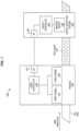
FIG. 1 is a diagram of aprint system 100 in an illustrative embodiment. Theprint system 100 includes aprinter 120 and adefect detection system 150. Under normal printing operation, theprinter 120 receives a print job, generates rasterized print data for the print job with theprint controller 126, and transmits the rasterized print data for the print job to one or more print engines 127-128. The print engines 127-128 mark theweb 130 of print media (e.g., paper, textile, printable substrate) with ink (e.g., marking material, colorant, etc.) according to the rasterized print data, thus producing printed output. - Occasionally, to verify that the print engines 127-128 are operating correctly, the
print controller 126 instructs the print engines 127-128 to print atest chart 140 based on test chart print data ontoweb 130 that can be analyzed manually or by thedefect detection system 150 for print defects. Thedefect detection system 150 includes aninterface 152, adefect controller 154, and one or more imaging device(s) 156. Theimaging device 156 may comprise a camera, scanner, densitometer, spectrophotometer or other suitable component for acquiring images of printed content. Thetest chart 140 may be printed on theweb 130 separately from the print jobs or with the print jobs (e.g. on sections of theweb 130 separate from the sections of theweb 130 printed with the print jobs). - After obtaining an image of the
test chart 140 via theimaging device 156, thedefect controller 154 analyzes the image for jet defects. For example, thedefect controller 154 may be configured to determine which printheads or nozzles printed the defects based on the location of the defect in thetest chart 140. Thedefect detection system 150 andprinter 120 may communicate viainterfaces 122/152 (e.g., an Ethernet interface, wireless interface, etc.). For instance, theprint controller 126 may transmit a rasterized version of the print data corresponding totest chart 140 to thedefect detection system 150 for comparison to an image of thetest chart 140 to determine whether there are any discrepancies that indicate printing errors, and thedefect detection system 150 may report (e.g., transmit) print defect data to theprinter 120 or other systems to inform maintenance procedures. - As described in greater detail below, the
defect controller 154 is enhanced to classify print defects by category or type.FIGS. 2A-D illustrate different types of print defects.FIG. 2A shows jet-outdefects 201 on thetest chart 140. Jet-out defects 201 may be caused by a complete blocking of a nozzle (e.g., no ink ejected).FIG. 2B shows a deviatedjet defect 202 on thetest chart 140.Deviated jet defects 202 may be caused by a partial blocking of a nozzle (e.g., ink ejected at least partially to an unintended location on web 130).FIG. 2C shows delaminatedprint head defects 203 on thetest chart 140.Delaminated head defects 203 may be caused by film on the printhead array peeling off from wear and tear (e.g., a plurality of adjacent nozzles partially blocked or fully blocked).FIG. 2D shows an unknown defect 204 on thetest chart 140. Unknown defects 204 may comprise a category of defects other than that which can be classified into the other print defect categories. Those skilled in the art will appreciate that further nozzle defect types or sub-types may also be defined. -
FIG. 3 is a block diagram of aprinter 300 in an illustrative embodiment. Theprinter 300 includes thedefect detection system 150 enhanced to determine the type or category of a particular print defect. That is, thedefect detection system 150 is configured to categorize print defects as one of a jet-out defect 201, deviatedjet defect 202,delaminated head defect 203, or unknown defect 204. By classifying print defects by type, thedefect detection system 150 is able to provide operational health data of theprinter 300 and facilitate corrective actions to take for efficiently improving print quality. Those skilled in the art will appreciate thatdefect detection system 150 may be used for other defect type also. - The
printer 300 generally includes a plurality of color planes 330 (e.g., cyan, magenta, yellow, and black) andprint engines 332. Eachprint engine 332 may process print data for one or a plurality ofcolor planes 330 and control one or a plurality ofprintheads 334 based on the print data. Eachprinthead 334 includes an array ofnozzles 336 that eject drops ofink 338 for printing. Thenozzles 336 of eachprinthead 334 may be assigned to one color plane or divided between a plurality of color planes 330. Theprintheads 334 may be configured physically in the web direction and/or orthogonal to the web direction. As earlier described, in the course of normal printing operation one or more of thenozzles 336 may clog with ink, resulting in print defects. Additionally, eachprinthead 334 may include hundreds ofnozzles 336. Due to quantity of ink drops 338 jetted bynozzles 336, the small individual size of the ink drops 338, and similarities in resemblance of different defect types to the human eye, it is difficult and time consuming even for a trained print operator to analyze printed test charts for defect types. - The
defect detection system 150 is enhanced with thedefect controller 154 configured to detect a nozzle defect in an image based on a comparison of the image withprint data 356, and to determine a type of the nozzle defect based on a comparison of the nozzle defect with the defect reference data. In doing so, thedefect controller 154 may take into account data stored indata storage 350, including any combination of currentnozzle defect information 351,defect reference data 352, andprint system settings 353. Examples of currentnozzle defect information 351 include any combination of nozzle defect type,corresponding nozzle 336 location, correspondingprinthead 334 identification, correspondingprint engine 332, correspondingprinter 300 and/orcolor plane 330. Examples ofprint system settings 353 include a print resolution, selected test pattern type, media type, and/or print engine parameters (e.g., print engine model, print width, paper handling orientation in the print engine, printhead type, ink type, etc.). - The
data storage 350 may also storeimage data 355 of thetest chart 140 captured by theimaging device 156 and/orprint data 356 corresponding to thetest chart 140. Additionally, thedata storage 350 may storeprinter configuration information 354 that may comprise information that correlates print locations,nozzles 336,printheads 334,print engines 332, color planes 330, and/or ink types (e.g. ink sets or specific ink colors). Thedefect controller 154 may be communicatively coupled with aninterface 346 and/or agraphical user interface 348 for receiving user input and/or displaying notifications to the user of theprinter 300. - While the specific hardware implementation of the
defect controller 154 is subject to design choices, one particular embodiment may include one ormore processors 342 coupled with amemory 344. Theprocessor 342 includes any electronic circuits and/or optical circuits that are able to perform functions. For example, a processor may include one or more Central Processing Units (CPU), Graphics Processing Unit (GPU), microprocessors, Digital Signal Processors (DSPs), Application-Specific Integrated Circuits (ASICs), Programmable Logic Devices (PLD), control circuitry, etc. Some examples of processors include Intel Core processors, Advanced Reduced Instruction Set Computing (RISC) Machines (ARM) processors, etc. Thememory 344 includes any hardware device that is able to store data. Thememory 344 may include one or more volatile or non-volatile Dynamic Random Access Memory (DRAM) devices, FLASH devices, volatile or non-volatile Static RAM devices, hard drives, Solid State Disks (SSDs), etc. Some examples of non-volatile DRAM and SRAM include battery-backed DRAM and battery-backed SRAM. Thedata storage 350 may similarly be implemented by any combination of memory devices or components. - The particular arrangement, number, and configuration of components described with respect to
FIG. 3 is an example for purposes of discussion and are non-limiting. For example, though thedefect detection system 150 is shown as incorporated in theprinter 300, portions or an entirety of thedefect detection system 150 and functions performed thereby may be implemented in a separate system that is near to the printer 300 (e.g. Digital Front End (DFE)) or remotely as a standalone system (e.g., cloud implementation) in communication with theprinter 300. Illustrative details of the operation of thedefect detection system 150 will be discussed with regard toFIGS. 4-5 . -
FIG. 4 is a flowchart illustrating amethod 400 of determining a type of print defect in an illustrative embodiment. The steps ofmethod 400 are described with reference to theprinter 300 anddefect detection system 150 ofFIG. 3 , but those skilled in the art will appreciate thatmethod 400 may be performed in other systems. The steps of the flowcharts described herein are not all inclusive and may include other steps not shown. The steps described herein may also be optionally performed or performed in an alternative order. - In
step 402, thedefect controller 154 may receive (e.g., via interface 346) and/or store (e.g., indata storage 350 or a memory) print data (e.g., print data 356), and an image of media printed on with the print data (e.g., image data 355).Print data 356 corresponds to the source print data that instructed the printing oftest chart 140 and may be in any suitable format for processing such as bitmaps, print description language or print job. In some embodiments,print data 356 for a test chart is incorporated and available withindefect reference data 352. Instep 404, thedefect controller 154 stores (e.g., indata storage 350 or a memory)defect reference data 352 ofnozzles 336 belonging toprintheads 334 of aprinter 300. Thedefect reference data 352 includes rules for thedefect controller 154 to use for interpreting the input image and determining defect types.Defect reference data 352 includes rules for determining optical density variations beyond a threshold (e.g., missing or unintended ink placement) inimage data 355 locations using a template based ontest chart 140. Thedefect reference data 352 may be derived from images that exhibit characteristics of a previously defined print defect type. For example, thedefect reference data 352 may be based on example print defect images that have been previously categorized either manually or by thedefect controller 154.Defect reference data 352 may be available for each category of print defects (e.g., a jet-out defect category, deviated defect category, delaminated head defect category, and an unknown category). - In
step 406, thedefect controller 154 detects a nozzle defect in the image based on a comparison of the image with theprint data 356. In doing so, thedefect controller 154 may analyzeimage data 355 of thetest chart 140 for discrepancies withprint data 356 and stores currentnozzle defect information 351 indata storage 350. Additionally, thedefect controller 154 may correlate defect locations within thetest chart 140 orimage data 355 withindividual nozzles 336,printheads 334,print engines 332, and/orprinter 300 that printed a defect based on information of theprinter configuration 354 and/orprint data 356 stored indata storage 350. - In
step 408, thedefect controller 154 determines a type of the nozzle defect based on a comparison of the nozzle defect image characteristics with thedefect reference data 352. For instance, thedefect controller 154 may identify a matching or similar pattern in thedefect reference data 352 or a common characteristic among defects within the same category, and determine the category to which the nozzle defect belongs based on a match of characteristics in the nozzle defect with that in the pattern or commonality defined in thedefect reference data 352. As earlier described, thedefect controller 154 may determine whether the nozzle defect is one of a jet-out (caused due to complete blocking of a nozzle), a deviated jet (caused by a partial blocking of a nozzle), delaminated head (caused by film on the printhead array peeling off from wear and tear), and unknown (other causes). In some embodiments, thedefect controller 154 determines a type of the nozzle defect with look up tables, programmed logic, and/or trained machine learning processor(s). Themethod 400 provides a benefit over prior techniques by assigning a print defect to a particular classification of inkjet nozzle defects without reliance on trained human operators. -
FIG. 5 is a flowchart illustrating amethod 500 of determining a type of print defect in another illustrative embodiment. The steps ofmethod 500 are described with reference to theprinter 300 anddefect detection system 150 ofFIG. 3 , but those skilled in the art will appreciate thatmethod 500 may be performed in other systems. The steps of the flowcharts described herein are not all inclusive and may include other steps not shown. The steps described herein may also be optionally performed or performed in an alternative order. - In
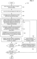
step 502, theimaging device 156 scans or captures a printed test chart to create a grayscale image (e.g., image data 355). Ifimage data 355 has been stored indata storage 350, then step 502 may be optionally skipped. Instep 504, thedefect controller 154 aligns the grayscale image with theprint data 356. The alignment may include adjustment of comparison inputs to account for the edge registration of print engine(s) 332 (e.g., center, left, or right justified) and/or skew. For example, if the printed test master is not printed on a full width of the medium, thedefect controller 154 may align the image to left if a first print engine printed the chart, and align the image to the right if a second print engine printed the test chart. Additionally, thedefect controller 154 may adjustimage data 355 for stretching/shrinkage in the printed medium, and may apply a position correction that is varied for each printhead to better align the grayscale image to theprint data 356 for each specific printhead. - In
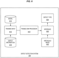
step 506, thedefect controller 154 determines defect information of one or more print defects in the grayscale image. And, instep 508, thedefect controller 154 determines the type of nozzle defect with a machine learning function using the defect information as input to the machine learning function.FIG. 6 is a block diagram of thedefect detection system 150 implementing a machine learning function in an illustrative embodiment. Thedefect detection system 150 includes a trained Deep Neural Network (DNN)processor 610 to automatically detect and localize multiple types of jetting defects at an individual nozzle level. - The
DNN processor 610 receives trained input viatraining input 612 that takes into account a model 614 anddefect information 616. The trainedDNN processor 610 is configured to produceinference 620 that analyzes pixels in thegreyscale image 622 and assigns adefect type 624 to an individual pixel based on pattern recognition. In some embodiments, the trainedDNN processor 610 implements as class of neural networks referred to as Convolutional Neural Networks (CNN). In some embodiments, theDNN processor 610 is trained withtraining input 612 that includestest chart 140 ofmethod 500. - Returning to
FIG. 5 , step 508 may comprise further steps 510-512. Instep 510, the trainedDNN processor 610 detects types of print defects based on a comparison of thegreyscale image 622 with theprint data 356, and also based ondefect information 616 input to the trainedDNN processor 610. Thedefect information 616 may include thedefect reference data 352, defect location, and/orprint system settings 353. For example, the trainedDNN processor 610 may determine the type of print defect based, at least part, on theprint engine 332 that printed the defect and the location of the defect relative to theprint engine 332. In some embodiments, the model 614 may be trained specific to aprint engine 332,printhead 334, media type, etc. to adapt to changing configurations/specifications of theprinter 300 to obtain higher detection accuracy. - In
step 512, the trainedDNN processor 610 determines a degree of matching between a nozzle defect detected in thegreyscale image 622 and thedefect reference data 352 for one of or each category of print defect. The degree of matching may include a percentage between zero and one hundred indicating a prediction or confidence level that the nozzle defect belongs to one of the specific predefined nozzle defects in thedefect reference data 352. Instep 514, thedefect controller 154 reports the nozzle defect location and confidence level that the assigned type of defect is correct for the nozzle defect. - In
step 516, thedefect controller 154 determines whether the degree of matching is uncertain for the nozzle defect (e.g., whether the degree of matching is beyond a threshold for each category of defect). If so, themethod 500 proceeds to step 518, and thedefect controller 154 generates a message for display indicating to perform a manual review of the nozzle defect. Then, instep 520, thedefect controller 154 updates thedefect reference data 352 based on received manual review data of the nozzle defect (e.g., reviewed nozzle defect data received viaGUI 348 and/or I/F 346), and themethod 500 returns to step 508. Accordingly, the trainedDNN processor 610 may generate pixel masks for different defect categories trained with hand-labeled datasets. This enables the trainedDNN processor 610 to adapt to real world input variation and noise in the original training set to continuously improve defect type prediction accuracy. Moreover, difficult cases with low confidence scores may be automatically collected to grow the training dataset, and other sub-categories of unknown defects may be discovered and incorporated in the future. - Otherwise, if the degree of matching is certain, the
method 500 proceeds to step 522 and thedefect controller 154 determines whether there are additional defects in thegreyscale image 622. If so, themethod 500 returns to step 508 and repeats. Otherwise, themethod 500 ends. Accordingly, themethod 500 provides a benefit over prior techniques by rapidly and automatically distinguishing between different types of print defects with high accuracy. Although certain steps ofmethod 500 are described with respect to thedefect controller 154 or the trainedDNN processor 610, it will be appreciated that the steps of themethod 500 may optionally be performed in alternative systems or types of processor(s). - Embodiments disclosed herein can take the form of software, hardware, firmware, or various combinations thereof. In one particular embodiment, software is used to direct a processing system of the
defect detection system 150 to perform the various operations disclosed herein.FIG. 7 illustrates aprocessing system 700 operable to execute a computer readable medium embodying programmed instructions to perform desired functions in an illustrative embodiment.Processing system 700 is operable to perform the above operations by executing programmed instructions tangibly embodied on computerreadable storage medium 712. In this regard, embodiments of the invention can take the form of a computer program accessible via computer-readable medium 712 providing program code for use by a computer or any other instruction execution system. For the purposes of this description, computerreadable storage medium 712 can be anything that can contain or store the program for use by the computer. - Computer
readable storage medium 712 can be an electronic, magnetic, optical, electromagnetic, infrared, or semiconductor device. Examples of computerreadable storage medium 712 include a solid state memory, a magnetic tape, a removable computer diskette, a random access memory (RAM), a read-only memory (ROM), a rigid magnetic disk, and an optical disk. Current examples of optical disks include compact disk - read only memory (CD-ROM), compact disk - read/write (CD-R/W), and DVD. -
Processing system 700, being suitable for storing and/or executing the program code, includes at least oneprocessor 702 coupled to program anddata memory 704 through asystem bus 750. Program anddata memory 704 can include local memory employed during actual execution of the program code, bulk storage, and cache memories that provide temporary storage of at least some program code and/or data in order to reduce the number of times the code and/or data are retrieved from bulk storage during execution. - Input/output or I/O devices 706 (including but not limited to keyboards, displays, pointing devices, etc.) can be coupled either directly or through intervening I/O controllers. Network adapter interfaces 708 may also be integrated with the system to enable
processing system 700 to become coupled to other data processing systems or storage devices through intervening private or public networks. Modems, cable modems, IBM Channel attachments, SCSI, Fibre Channel, and Ethernet cards are just a few of the currently available types of network or host interface adapters.Display device interface 710 may be integrated with the system to interface to one or more display devices, such as printing systems and screens for presentation of data generated byprocessor 702. - Although specific embodiments were described herein, the scope of the invention is not limited to those specific embodiments. The scope of the invention is defined by the following claims.
Claims (15)
- A system comprising:an imaging device (156) configured to acquire an image of a test chart (140) printed on media (130) and print data (356) corresponding to source print data for instructing printing of the test chart (140);memory (350) configured to store defect reference data (352) of nozzles belonging to printheads of a printer, the defect reference data (352) including rules for determining defect types and optical density variations; anda print defect controller (154) configured to detect a nozzle defect in the image based on a comparison of the image with the print data (356), and to determine defect type and the optical density variations based on a comparison of the nozzle defect with the defect reference data (352) by using the rules.
- The system of claim 1, wherein
the print defect controller (154) is further configured to determine whether a type of the nozzle defect is one of a deviated nozzle defect, a clogged nozzle defect, and a delaminated nozzle defect. - The system of claim 2, wherein
the print defect controller (154) is further configured to determine a degree of matching between the nozzle defect and the defect reference data (352) for each of the deviated nozzle defect, the clogged nozzle defect, and the delaminated nozzle defect. - The system of claim 3, wherein
the print defect controller (154) is further configured, in response to determining that the degree of matching of the nozzle defect is uncertain, to generate a message for display indicating to perform a manual review of the nozzle defect. - The system of claim 4, wherein
the print defect controller (154) is further configured to update the defect reference data (352) based on received manual review data of the nozzle defect. - The system of claim 1, wherein
the print defect controller (154) is further configured to determine the type of the nozzle defect based at least in part on a location of the nozzle defect and one or more print system settings. - The system of claim 1, further comprisinga printer (300) comprisinga print engine (332) including printheads each having a plurality of nozzles configured to eject ink.
- A method, comprising:storing, in memory, defect reference data (352) of nozzles belonging to printheads of a printer, the defect reference data (352) including rules for determining defect types and optical density variations;acquiring an image of a test chart (140) printed on media (130) and print data (356) corresponding to the test chart (140);detecting a nozzle defect in the image based on a comparison of the image with the print data (356); anddetermining the defect types and optical density variations based on a comparison of the nozzle defect with the defect reference data (352) by using the rules.
- A tangible computer readable medium including programmed instructions which, when executed by a processor of a system of any of claims 1 to 7, are operable for performing the method according to the preceding claim.
- The medium of claim 9, wherein the method further comprises
determining whether a type of the nozzle defect is one of a deviated nozzle defect, a clogged nozzle defect, and a delaminated nozzle defect. - The medium of claim 10, wherein the method further comprises
determining a degree of matching between the nozzle defect and the defect reference data (352) for each of the deviated nozzle defect, the clogged nozzle defect, and the delaminated nozzle defect. - The medium of claim 11, wherein the method further comprises
in response to determining that the degree of matching of the nozzle defect is uncertain, generating a message for display indicating to perform a manual review of the nozzle defect. - The medium of claim 12, wherein the method further comprises
updating the defect reference data (352) based on received manual review data of the nozzle defect. - The medium of claim 9, wherein the method further comprises
determining the type of the nozzle defect based at least in part on a location of the nozzle defect and one or more print system settings. - The medium of claim 9, wherein the method further comprises
determining the type of the nozzle defect with a machine learning function using the defect reference data (352) as input to the machine learning function.
Applications Claiming Priority (1)
| Application Number | Priority Date | Filing Date | Title |
|---|---|---|---|
| US16/712,985 US11734814B2 (en) | 2019-12-12 | 2019-12-12 | Enhanced print defect detection |
Publications (2)
| Publication Number | Publication Date |
|---|---|
| EP3835069A1 EP3835069A1 (en) | 2021-06-16 |
| EP3835069B1 true EP3835069B1 (en) | 2024-07-17 |
Family
ID=73793016
Family Applications (1)
| Application Number | Title | Priority Date | Filing Date |
|---|---|---|---|
| EP20213007.6A Active EP3835069B1 (en) | 2019-12-12 | 2020-12-10 | Enhanced print defect detection |
Country Status (3)
| Country | Link |
|---|---|
| US (3) | US11734814B2 (en) |
| EP (1) | EP3835069B1 (en) |
| JP (1) | JP7476088B2 (en) |
Families Citing this family (13)
| Publication number | Priority date | Publication date | Assignee | Title |
|---|---|---|---|---|
| JP7482662B2 (en) * | 2020-03-25 | 2024-05-14 | 東京エレクトロン株式会社 | Anomaly detection device and anomaly detection method |
| WO2021204480A1 (en) * | 2020-04-10 | 2021-10-14 | Memjet Technology Limited | Method of evaluating printhead condition |
| EP3954540B1 (en) * | 2020-08-11 | 2024-12-11 | Schott Ag | Method for printing an image on a substrate and corresponding system |
| US11314465B1 (en) | 2021-02-23 | 2022-04-26 | Ricoh Company, Ltd. | Dynamic scan quality control management for print jobs |
| US11305552B1 (en) | 2021-02-23 | 2022-04-19 | Ricoh Company, Ltd. | Dynamic scan quality control management for print jobs |
| US11310379B1 (en) * | 2021-03-08 | 2022-04-19 | Ricoh Company, Ltd. | Printhead state GUI for printers |
| KR102822585B1 (en) * | 2021-12-28 | 2025-06-18 | 세메스 주식회사 | Nozzle inspecting unit and substrate treating apparatus including the same |
| US12179480B2 (en) | 2022-07-14 | 2024-12-31 | Ricoh Company, Ltd. | Detection of printhead conditions based on isolation scoring |
| US12090767B2 (en) | 2022-09-29 | 2024-09-17 | Ricoh Company, Ltd. | Defective nozzle locating mechanism |
| US12459264B2 (en) | 2023-03-03 | 2025-11-04 | Ricoh Company, Ltd. | Printhead maintenance for recommending printhead replacement |
| JP2024137555A (en) | 2023-03-25 | 2024-10-07 | 株式会社Screenホールディングス | Printing device, method for detecting defective discharge, and program for detecting defective discharge |
| JP2024137554A (en) | 2023-03-25 | 2024-10-07 | 株式会社Screenホールディングス | Printing device, method for detecting defective discharge, and program for detecting defective discharge |
| WO2024228075A1 (en) * | 2023-05-01 | 2024-11-07 | Landa Corporation Ltd. | Unified calibrations in a digital printing system |
Family Cites Families (37)
| Publication number | Priority date | Publication date | Assignee | Title |
|---|---|---|---|---|
| FR2801836B1 (en) * | 1999-12-03 | 2002-02-01 | Imaje Sa | SIMPLIFIED MANUFACTURING PRINTER AND METHOD OF MAKING |
| US6905186B2 (en) | 2002-07-30 | 2005-06-14 | Fuji Photo Film Co., Ltd. | Image recording apparatus |
| US7287824B2 (en) | 2004-07-16 | 2007-10-30 | Hewlett-Packard Development Company, L.P. | Method and apparatus for assessing nozzle health |
| JP5006520B2 (en) * | 2005-03-22 | 2012-08-22 | 株式会社日立ハイテクノロジーズ | Defect observation apparatus and defect observation method using defect observation apparatus |
| JP4872979B2 (en) * | 2008-07-25 | 2012-02-08 | 富士ゼロックス株式会社 | Image processing apparatus, image forming apparatus, and program |
| AU2008258159A1 (en) | 2008-12-16 | 2010-07-01 | Canon Kabushiki Kaisha | Nozzle functionality detection of inkjet printers |
| JP5649395B2 (en) * | 2009-10-08 | 2015-01-07 | 富士フイルム株式会社 | Inkjet recording apparatus and method, and abnormal nozzle detection method |
| US8814316B2 (en) | 2011-01-31 | 2014-08-26 | Canon Kabushiki Kaisha | Inkjet printing apparatus with defective nozzle detection |
| US9378546B2 (en) | 2012-01-12 | 2016-06-28 | Hewlett-Packard Indigo B.V. | Image defect visibility predictor |
| JP2013169760A (en) | 2012-02-22 | 2013-09-02 | Fujifilm Corp | Inkjet recording apparatus and image recording method |
| US8820880B2 (en) | 2012-04-04 | 2014-09-02 | Ricoh Production Print Solutions LLC | Defective nozzle detection mechanism |
| JP5584733B2 (en) | 2012-06-08 | 2014-09-03 | キヤノン株式会社 | Recording apparatus and printed matter discharge method |
| TWI607889B (en) * | 2012-09-21 | 2017-12-11 | 滿捷特科技公司 | Method, printing medium and device for discriminating defective nozzles in an inkjet head |
| JP6232999B2 (en) | 2013-03-15 | 2017-11-22 | 株式会社リコー | Image inspection apparatus, image inspection system, and image inspection method |
| JP5839609B2 (en) * | 2013-04-17 | 2016-01-06 | 富士フイルム株式会社 | Image recording apparatus, control method therefor, and program |
| JP6131825B2 (en) | 2013-10-25 | 2017-05-24 | 富士ゼロックス株式会社 | Image forming apparatus and program |
| US20150177158A1 (en) * | 2013-12-13 | 2015-06-25 | General Electric Company | Operational performance assessment of additive manufacturing |
| US11691413B2 (en) * | 2014-06-13 | 2023-07-04 | Electronics For Imaging, Inc. | Integration of a line-scan camera on a single pass inkjet printer |
| EP3359727A4 (en) * | 2015-10-08 | 2019-05-15 | Kornit Digital Ltd. | DISSIMULATION OF MISSING NOZZLES |
| JP6472083B2 (en) | 2015-11-02 | 2019-02-20 | 富士フイルム株式会社 | Inkjet printing apparatus and inkjet head ejection performance evaluation method |
| DE102016100057A1 (en) | 2016-01-04 | 2017-07-06 | Océ Holding B.V. | Method for determining the print quality of an inkjet printing system |
| US10124618B2 (en) * | 2016-02-12 | 2018-11-13 | Ricoh Company, Ltd. | Inspection apparatus and method of inspection |
| EP3442798B1 (en) | 2016-04-11 | 2022-04-13 | Advanced Vision Technology (AVT) Ltd. | System and methods for detecting malfunctioning nozzles in a digital printing press |
| US10507670B2 (en) * | 2016-07-08 | 2019-12-17 | Electronics For Imaging, Inc. | Nozzle compensation for shuttle based printers |
| JP6576316B2 (en) * | 2016-09-27 | 2019-09-18 | 富士フイルム株式会社 | Image inspection apparatus and method, program, and inkjet printing system |
| JP6659873B2 (en) * | 2016-12-02 | 2020-03-04 | 富士フイルム株式会社 | Image recording apparatus and image recording method |
| JP6838424B2 (en) * | 2017-02-23 | 2021-03-03 | ブラザー工業株式会社 | Image processing equipment and computer programs |
| JP2018153922A (en) | 2017-03-15 | 2018-10-04 | ローランドディー.ジー.株式会社 | Cleaning time prediction device and print system |
| DE102018217476A1 (en) * | 2017-11-22 | 2019-05-23 | Heidelberger Druckmaschinen Ag | Variable pressure nozzle test pattern |
| JP2019101540A (en) | 2017-11-29 | 2019-06-24 | 大日本印刷株式会社 | Facility diagnostic device, facility diagnostic method, and program |
| US10834283B2 (en) | 2018-01-05 | 2020-11-10 | Datamax-O'neil Corporation | Methods, apparatuses, and systems for detecting printing defects and contaminated components of a printer |
| DE102018202027B3 (en) * | 2018-02-09 | 2018-11-22 | Heidelberger Druckmaschinen Ag | Method for detecting defective printing nozzles in an inkjet printing machine |
| JP7062991B2 (en) * | 2018-02-13 | 2022-05-09 | コニカミノルタ株式会社 | Detection device, inkjet recording device and detection method |
| DE102018114005A1 (en) * | 2018-06-12 | 2019-12-12 | Carl Zeiss Jena Gmbh | Material testing of optical specimens |
| US20200393998A1 (en) * | 2019-06-17 | 2020-12-17 | Kyocera Document Solutions Inc. | Multifunction Printer and Printer Engine Defect Detection and Handling Using Machine Learning |
| US20220222803A1 (en) * | 2019-09-26 | 2022-07-14 | Hewlett-Packard Development Company, L.P. | Labeling pixels having defects |
| JP7489030B2 (en) * | 2020-09-02 | 2024-05-23 | セイコーエプソン株式会社 | Printing device and method for producing printed matter |
-
2019
- 2019-12-12 US US16/712,985 patent/US11734814B2/en active Active
-
2020
- 2020-12-10 EP EP20213007.6A patent/EP3835069B1/en active Active
- 2020-12-11 JP JP2020205809A patent/JP7476088B2/en active Active
-
2023
- 2023-07-04 US US18/218,052 patent/US12315139B2/en active Active
-
2025
- 2025-04-28 US US19/192,091 patent/US20250259300A1/en active Pending
Also Published As
| Publication number | Publication date |
|---|---|
| JP7476088B2 (en) | 2024-04-30 |
| US12315139B2 (en) | 2025-05-27 |
| US11734814B2 (en) | 2023-08-22 |
| US20250259300A1 (en) | 2025-08-14 |
| US20210183036A1 (en) | 2021-06-17 |
| US20230351583A1 (en) | 2023-11-02 |
| JP2021094853A (en) | 2021-06-24 |
| EP3835069A1 (en) | 2021-06-16 |
Similar Documents
| Publication | Publication Date | Title |
|---|---|---|
| EP3835069B1 (en) | Enhanced print defect detection | |
| US11273636B2 (en) | Adaptive printhead cleaning | |
| EP3305532B1 (en) | Image inspection device, image inspection method, program, and ink jet printing system | |
| US10166761B2 (en) | Image forming apparatus and image correcting method with correction technology for improvement of defective images | |
| US8944553B2 (en) | Flush line generation in printing systems that utilize control marks | |
| US11579827B1 (en) | Self-configuring inspection systems for printers | |
| CN111152562B (en) | Ink cartridge spray point detection method, system, readable storage medium and device | |
| US20230278329A1 (en) | Printing system and defective nozzle detection method | |
| EP4056378B1 (en) | Dynamic scan quality control management for print jobs | |
| US8820880B2 (en) | Defective nozzle detection mechanism | |
| JP2013024592A (en) | Image inspection device, image recorder, and image inspection method | |
| JP7559315B2 (en) | Dynamic scan quality control management for print jobs | |
| JP2011005718A (en) | Program, device and method for specifying clogged nozzle | |
| US20260030868A1 (en) | Streak-shaped defect classification method and streak-shaped defect classification system | |
| EP3842918B1 (en) | Defect size detection mechanism | |
| CN119445193B (en) | Image printing processing method, device, equipment and storage medium | |
| US11999166B2 (en) | Adaptive ink flushing of overlap nozzles of a printer | |
| EP4691779A1 (en) | Printer, ejection failure detection method, and ejection failure detection program | |
| EP4316860B1 (en) | Printing system | |
| US20250291526A1 (en) | Automatic inspection template generation mechanism | |
| US11310379B1 (en) | Printhead state GUI for printers | |
| US20250301065A1 (en) | Information processing system, non-transitory computer readable medium storing information processing program, and inspection apparatus | |
| JP6050838B2 (en) | Dot detection method and color image reproduction apparatus | |
| JP7482638B2 (en) | Image processing device, halftone image generating device, printing system, and image processing method |
Legal Events
| Date | Code | Title | Description |
|---|---|---|---|
| PUAI | Public reference made under article 153(3) epc to a published international application that has entered the european phase |
Free format text: ORIGINAL CODE: 0009012 |
|
| STAA | Information on the status of an ep patent application or granted ep patent |
Free format text: STATUS: REQUEST FOR EXAMINATION WAS MADE |
|
| 17P | Request for examination filed |
Effective date: 20201210 |
|
| AK | Designated contracting states |
Kind code of ref document: A1 Designated state(s): AL AT BE BG CH CY CZ DE DK EE ES FI FR GB GR HR HU IE IS IT LI LT LU LV MC MK MT NL NO PL PT RO RS SE SI SK SM TR |
|
| STAA | Information on the status of an ep patent application or granted ep patent |
Free format text: STATUS: EXAMINATION IS IN PROGRESS |
|
| 17Q | First examination report despatched |
Effective date: 20230703 |
|
| GRAP | Despatch of communication of intention to grant a patent |
Free format text: ORIGINAL CODE: EPIDOSNIGR1 |
|
| STAA | Information on the status of an ep patent application or granted ep patent |
Free format text: STATUS: GRANT OF PATENT IS INTENDED |
|
| INTG | Intention to grant announced |
Effective date: 20240228 |
|
| P01 | Opt-out of the competence of the unified patent court (upc) registered |
Effective date: 20240410 |
|
| GRAS | Grant fee paid |
Free format text: ORIGINAL CODE: EPIDOSNIGR3 |
|
| GRAA | (expected) grant |
Free format text: ORIGINAL CODE: 0009210 |
|
| STAA | Information on the status of an ep patent application or granted ep patent |
Free format text: STATUS: THE PATENT HAS BEEN GRANTED |
|
| AK | Designated contracting states |
Kind code of ref document: B1 Designated state(s): AL AT BE BG CH CY CZ DE DK EE ES FI FR GB GR HR HU IE IS IT LI LT LU LV MC MK MT NL NO PL PT RO RS SE SI SK SM TR |
|
| REG | Reference to a national code |
Ref country code: CH Ref legal event code: EP |
|
| REG | Reference to a national code |
Ref country code: DE Ref legal event code: R096 Ref document number: 602020034048 Country of ref document: DE |
|
| REG | Reference to a national code |
Ref country code: IE Ref legal event code: FG4D |
|
| REG | Reference to a national code |
Ref country code: LT Ref legal event code: MG9D |
|
| REG | Reference to a national code |
Ref country code: NL Ref legal event code: MP Effective date: 20240717 |
|
| PG25 | Lapsed in a contracting state [announced via postgrant information from national office to epo] |
Ref country code: PT Free format text: LAPSE BECAUSE OF FAILURE TO SUBMIT A TRANSLATION OF THE DESCRIPTION OR TO PAY THE FEE WITHIN THE PRESCRIBED TIME-LIMIT Effective date: 20241118 |
|
| REG | Reference to a national code |
Ref country code: AT Ref legal event code: MK05 Ref document number: 1703773 Country of ref document: AT Kind code of ref document: T Effective date: 20240717 |
|
| PG25 | Lapsed in a contracting state [announced via postgrant information from national office to epo] |
Ref country code: NL Free format text: LAPSE BECAUSE OF FAILURE TO SUBMIT A TRANSLATION OF THE DESCRIPTION OR TO PAY THE FEE WITHIN THE PRESCRIBED TIME-LIMIT Effective date: 20240717 |
|
| PG25 | Lapsed in a contracting state [announced via postgrant information from national office to epo] |
Ref country code: PT Free format text: LAPSE BECAUSE OF FAILURE TO SUBMIT A TRANSLATION OF THE DESCRIPTION OR TO PAY THE FEE WITHIN THE PRESCRIBED TIME-LIMIT Effective date: 20241118 Ref country code: NL Free format text: LAPSE BECAUSE OF FAILURE TO SUBMIT A TRANSLATION OF THE DESCRIPTION OR TO PAY THE FEE WITHIN THE PRESCRIBED TIME-LIMIT Effective date: 20240717 |
|
| PG25 | Lapsed in a contracting state [announced via postgrant information from national office to epo] |
Ref country code: NO Free format text: LAPSE BECAUSE OF FAILURE TO SUBMIT A TRANSLATION OF THE DESCRIPTION OR TO PAY THE FEE WITHIN THE PRESCRIBED TIME-LIMIT Effective date: 20241017 |
|
| PG25 | Lapsed in a contracting state [announced via postgrant information from national office to epo] |
Ref country code: GR Free format text: LAPSE BECAUSE OF FAILURE TO SUBMIT A TRANSLATION OF THE DESCRIPTION OR TO PAY THE FEE WITHIN THE PRESCRIBED TIME-LIMIT Effective date: 20241018 Ref country code: FI Free format text: LAPSE BECAUSE OF FAILURE TO SUBMIT A TRANSLATION OF THE DESCRIPTION OR TO PAY THE FEE WITHIN THE PRESCRIBED TIME-LIMIT Effective date: 20240717 Ref country code: PL Free format text: LAPSE BECAUSE OF FAILURE TO SUBMIT A TRANSLATION OF THE DESCRIPTION OR TO PAY THE FEE WITHIN THE PRESCRIBED TIME-LIMIT Effective date: 20240717 |
|
| PG25 | Lapsed in a contracting state [announced via postgrant information from national office to epo] |
Ref country code: BG Free format text: LAPSE BECAUSE OF FAILURE TO SUBMIT A TRANSLATION OF THE DESCRIPTION OR TO PAY THE FEE WITHIN THE PRESCRIBED TIME-LIMIT Effective date: 20240717 |
|
| PG25 | Lapsed in a contracting state [announced via postgrant information from national office to epo] |
Ref country code: LV Free format text: LAPSE BECAUSE OF FAILURE TO SUBMIT A TRANSLATION OF THE DESCRIPTION OR TO PAY THE FEE WITHIN THE PRESCRIBED TIME-LIMIT Effective date: 20240717 |
|
| PG25 | Lapsed in a contracting state [announced via postgrant information from national office to epo] |
Ref country code: IS Free format text: LAPSE BECAUSE OF FAILURE TO SUBMIT A TRANSLATION OF THE DESCRIPTION OR TO PAY THE FEE WITHIN THE PRESCRIBED TIME-LIMIT Effective date: 20241117 Ref country code: AT Free format text: LAPSE BECAUSE OF FAILURE TO SUBMIT A TRANSLATION OF THE DESCRIPTION OR TO PAY THE FEE WITHIN THE PRESCRIBED TIME-LIMIT Effective date: 20240717 |
|
| PG25 | Lapsed in a contracting state [announced via postgrant information from national office to epo] |
Ref country code: HR Free format text: LAPSE BECAUSE OF FAILURE TO SUBMIT A TRANSLATION OF THE DESCRIPTION OR TO PAY THE FEE WITHIN THE PRESCRIBED TIME-LIMIT Effective date: 20240717 |
|
| PG25 | Lapsed in a contracting state [announced via postgrant information from national office to epo] |
Ref country code: ES Free format text: LAPSE BECAUSE OF FAILURE TO SUBMIT A TRANSLATION OF THE DESCRIPTION OR TO PAY THE FEE WITHIN THE PRESCRIBED TIME-LIMIT Effective date: 20240717 Ref country code: RS Free format text: LAPSE BECAUSE OF FAILURE TO SUBMIT A TRANSLATION OF THE DESCRIPTION OR TO PAY THE FEE WITHIN THE PRESCRIBED TIME-LIMIT Effective date: 20241017 |
|
| PG25 | Lapsed in a contracting state [announced via postgrant information from national office to epo] |
Ref country code: RS Free format text: LAPSE BECAUSE OF FAILURE TO SUBMIT A TRANSLATION OF THE DESCRIPTION OR TO PAY THE FEE WITHIN THE PRESCRIBED TIME-LIMIT Effective date: 20241017 Ref country code: PL Free format text: LAPSE BECAUSE OF FAILURE TO SUBMIT A TRANSLATION OF THE DESCRIPTION OR TO PAY THE FEE WITHIN THE PRESCRIBED TIME-LIMIT Effective date: 20240717 Ref country code: NO Free format text: LAPSE BECAUSE OF FAILURE TO SUBMIT A TRANSLATION OF THE DESCRIPTION OR TO PAY THE FEE WITHIN THE PRESCRIBED TIME-LIMIT Effective date: 20241017 Ref country code: LV Free format text: LAPSE BECAUSE OF FAILURE TO SUBMIT A TRANSLATION OF THE DESCRIPTION OR TO PAY THE FEE WITHIN THE PRESCRIBED TIME-LIMIT Effective date: 20240717 Ref country code: IS Free format text: LAPSE BECAUSE OF FAILURE TO SUBMIT A TRANSLATION OF THE DESCRIPTION OR TO PAY THE FEE WITHIN THE PRESCRIBED TIME-LIMIT Effective date: 20241117 Ref country code: HR Free format text: LAPSE BECAUSE OF FAILURE TO SUBMIT A TRANSLATION OF THE DESCRIPTION OR TO PAY THE FEE WITHIN THE PRESCRIBED TIME-LIMIT Effective date: 20240717 Ref country code: GR Free format text: LAPSE BECAUSE OF FAILURE TO SUBMIT A TRANSLATION OF THE DESCRIPTION OR TO PAY THE FEE WITHIN THE PRESCRIBED TIME-LIMIT Effective date: 20241018 Ref country code: FI Free format text: LAPSE BECAUSE OF FAILURE TO SUBMIT A TRANSLATION OF THE DESCRIPTION OR TO PAY THE FEE WITHIN THE PRESCRIBED TIME-LIMIT Effective date: 20240717 Ref country code: ES Free format text: LAPSE BECAUSE OF FAILURE TO SUBMIT A TRANSLATION OF THE DESCRIPTION OR TO PAY THE FEE WITHIN THE PRESCRIBED TIME-LIMIT Effective date: 20240717 Ref country code: BG Free format text: LAPSE BECAUSE OF FAILURE TO SUBMIT A TRANSLATION OF THE DESCRIPTION OR TO PAY THE FEE WITHIN THE PRESCRIBED TIME-LIMIT Effective date: 20240717 Ref country code: AT Free format text: LAPSE BECAUSE OF FAILURE TO SUBMIT A TRANSLATION OF THE DESCRIPTION OR TO PAY THE FEE WITHIN THE PRESCRIBED TIME-LIMIT Effective date: 20240717 |
|
| PG25 | Lapsed in a contracting state [announced via postgrant information from national office to epo] |
Ref country code: SM Free format text: LAPSE BECAUSE OF FAILURE TO SUBMIT A TRANSLATION OF THE DESCRIPTION OR TO PAY THE FEE WITHIN THE PRESCRIBED TIME-LIMIT Effective date: 20240717 Ref country code: DK Free format text: LAPSE BECAUSE OF FAILURE TO SUBMIT A TRANSLATION OF THE DESCRIPTION OR TO PAY THE FEE WITHIN THE PRESCRIBED TIME-LIMIT Effective date: 20240717 Ref country code: RO Free format text: LAPSE BECAUSE OF FAILURE TO SUBMIT A TRANSLATION OF THE DESCRIPTION OR TO PAY THE FEE WITHIN THE PRESCRIBED TIME-LIMIT Effective date: 20240717 |
|
| REG | Reference to a national code |
Ref country code: DE Ref legal event code: R097 Ref document number: 602020034048 Country of ref document: DE |
|
| PG25 | Lapsed in a contracting state [announced via postgrant information from national office to epo] |
Ref country code: EE Free format text: LAPSE BECAUSE OF FAILURE TO SUBMIT A TRANSLATION OF THE DESCRIPTION OR TO PAY THE FEE WITHIN THE PRESCRIBED TIME-LIMIT Effective date: 20240717 |
|
| PG25 | Lapsed in a contracting state [announced via postgrant information from national office to epo] |
Ref country code: CZ Free format text: LAPSE BECAUSE OF FAILURE TO SUBMIT A TRANSLATION OF THE DESCRIPTION OR TO PAY THE FEE WITHIN THE PRESCRIBED TIME-LIMIT Effective date: 20240717 |
|
| PG25 | Lapsed in a contracting state [announced via postgrant information from national office to epo] |
Ref country code: SK Free format text: LAPSE BECAUSE OF FAILURE TO SUBMIT A TRANSLATION OF THE DESCRIPTION OR TO PAY THE FEE WITHIN THE PRESCRIBED TIME-LIMIT Effective date: 20240717 |
|
| PLBE | No opposition filed within time limit |
Free format text: ORIGINAL CODE: 0009261 |
|
| STAA | Information on the status of an ep patent application or granted ep patent |
Free format text: STATUS: NO OPPOSITION FILED WITHIN TIME LIMIT |
|
| 26N | No opposition filed |
Effective date: 20250422 |
|
| PG25 | Lapsed in a contracting state [announced via postgrant information from national office to epo] |
Ref country code: MC Free format text: LAPSE BECAUSE OF FAILURE TO SUBMIT A TRANSLATION OF THE DESCRIPTION OR TO PAY THE FEE WITHIN THE PRESCRIBED TIME-LIMIT Effective date: 20240717 |
|
| REG | Reference to a national code |
Ref country code: CH Ref legal event code: PL |
|
| PG25 | Lapsed in a contracting state [announced via postgrant information from national office to epo] |
Ref country code: LU Free format text: LAPSE BECAUSE OF NON-PAYMENT OF DUE FEES Effective date: 20241210 |
|
| PG25 | Lapsed in a contracting state [announced via postgrant information from national office to epo] |
Ref country code: SE Free format text: LAPSE BECAUSE OF FAILURE TO SUBMIT A TRANSLATION OF THE DESCRIPTION OR TO PAY THE FEE WITHIN THE PRESCRIBED TIME-LIMIT Effective date: 20240717 |
|
| REG | Reference to a national code |
Ref country code: BE Ref legal event code: MM Effective date: 20241231 |
|
| PG25 | Lapsed in a contracting state [announced via postgrant information from national office to epo] |
Ref country code: BE Free format text: LAPSE BECAUSE OF NON-PAYMENT OF DUE FEES Effective date: 20241231 |
|
| PG25 | Lapsed in a contracting state [announced via postgrant information from national office to epo] |
Ref country code: CH Free format text: LAPSE BECAUSE OF NON-PAYMENT OF DUE FEES Effective date: 20241231 |
|
| PG25 | Lapsed in a contracting state [announced via postgrant information from national office to epo] |
Ref country code: IE Free format text: LAPSE BECAUSE OF NON-PAYMENT OF DUE FEES Effective date: 20241210 |
|
| PGFP | Annual fee paid to national office [announced via postgrant information from national office to epo] |
Ref country code: DE Payment date: 20251211 Year of fee payment: 6 |
|
| PGFP | Annual fee paid to national office [announced via postgrant information from national office to epo] |
Ref country code: GB Payment date: 20251219 Year of fee payment: 6 |
|
| PGFP | Annual fee paid to national office [announced via postgrant information from national office to epo] |
Ref country code: FR Payment date: 20251229 Year of fee payment: 6 |
|
| PG25 | Lapsed in a contracting state [announced via postgrant information from national office to epo] |
Ref country code: IT Free format text: LAPSE BECAUSE OF FAILURE TO SUBMIT A TRANSLATION OF THE DESCRIPTION OR TO PAY THE FEE WITHIN THE PRESCRIBED TIME-LIMIT Effective date: 20240717 |