EP3834999A1 - Work support device, system and method and computer program product - Google Patents
Work support device, system and method and computer program product Download PDFInfo
- Publication number
- EP3834999A1 EP3834999A1 EP20193078.1A EP20193078A EP3834999A1 EP 3834999 A1 EP3834999 A1 EP 3834999A1 EP 20193078 A EP20193078 A EP 20193078A EP 3834999 A1 EP3834999 A1 EP 3834999A1
- Authority
- EP
- European Patent Office
- Prior art keywords
- unit
- arm unit
- arm
- joint
- work support
- Prior art date
- Legal status (The legal status is an assumption and is not a legal conclusion. Google has not performed a legal analysis and makes no representation as to the accuracy of the status listed.)
- Granted
Links
Images





Classifications
-
- B—PERFORMING OPERATIONS; TRANSPORTING
- B25—HAND TOOLS; PORTABLE POWER-DRIVEN TOOLS; MANIPULATORS
- B25J—MANIPULATORS; CHAMBERS PROVIDED WITH MANIPULATION DEVICES
- B25J9/00—Program-controlled manipulators
- B25J9/16—Program controls
- B25J9/1628—Program controls characterised by the control loop
- B25J9/1651—Program controls characterised by the control loop acceleration, rate control
-
- B—PERFORMING OPERATIONS; TRANSPORTING
- B25—HAND TOOLS; PORTABLE POWER-DRIVEN TOOLS; MANIPULATORS
- B25J—MANIPULATORS; CHAMBERS PROVIDED WITH MANIPULATION DEVICES
- B25J9/00—Program-controlled manipulators
- B25J9/16—Program controls
- B25J9/1674—Program controls characterised by safety, monitoring, diagnostic
-
- B—PERFORMING OPERATIONS; TRANSPORTING
- B66—HOISTING; LIFTING; HAULING
- B66B—ELEVATORS; ESCALATORS OR MOVING WALKWAYS
- B66B5/00—Applications of checking, fault-correcting, or safety devices in elevators
- B66B5/0087—Devices facilitating maintenance, repair or inspection tasks
-
- B—PERFORMING OPERATIONS; TRANSPORTING
- B25—HAND TOOLS; PORTABLE POWER-DRIVEN TOOLS; MANIPULATORS
- B25J—MANIPULATORS; CHAMBERS PROVIDED WITH MANIPULATION DEVICES
- B25J13/00—Controls for manipulators
- B25J13/08—Controls for manipulators by means of sensing devices, e.g. viewing or touching devices
- B25J13/085—Force or torque sensors
-
- B—PERFORMING OPERATIONS; TRANSPORTING
- B25—HAND TOOLS; PORTABLE POWER-DRIVEN TOOLS; MANIPULATORS
- B25J—MANIPULATORS; CHAMBERS PROVIDED WITH MANIPULATION DEVICES
- B25J13/00—Controls for manipulators
- B25J13/08—Controls for manipulators by means of sensing devices, e.g. viewing or touching devices
- B25J13/088—Controls for manipulators by means of sensing devices, e.g. viewing or touching devices with position, velocity or acceleration sensors
-
- B—PERFORMING OPERATIONS; TRANSPORTING
- B25—HAND TOOLS; PORTABLE POWER-DRIVEN TOOLS; MANIPULATORS
- B25J—MANIPULATORS; CHAMBERS PROVIDED WITH MANIPULATION DEVICES
- B25J17/00—Joints
- B25J17/02—Wrist joints
-
- B—PERFORMING OPERATIONS; TRANSPORTING
- B25—HAND TOOLS; PORTABLE POWER-DRIVEN TOOLS; MANIPULATORS
- B25J—MANIPULATORS; CHAMBERS PROVIDED WITH MANIPULATION DEVICES
- B25J19/00—Accessories fitted to manipulators, e.g. for monitoring, for viewing; Safety devices combined with or specially adapted for use in connection with manipulators
- B25J19/0004—Braking devices
-
- B—PERFORMING OPERATIONS; TRANSPORTING
- B25—HAND TOOLS; PORTABLE POWER-DRIVEN TOOLS; MANIPULATORS
- B25J—MANIPULATORS; CHAMBERS PROVIDED WITH MANIPULATION DEVICES
- B25J9/00—Program-controlled manipulators
- B25J9/02—Program-controlled manipulators characterised by movement of the arms, e.g. cartesian coordinate type
- B25J9/04—Program-controlled manipulators characterised by movement of the arms, e.g. cartesian coordinate type by rotating at least one arm, excluding the head movement itself, e.g. cylindrical coordinate type or polar coordinate type
-
- B—PERFORMING OPERATIONS; TRANSPORTING
- B25—HAND TOOLS; PORTABLE POWER-DRIVEN TOOLS; MANIPULATORS
- B25J—MANIPULATORS; CHAMBERS PROVIDED WITH MANIPULATION DEVICES
- B25J9/00—Program-controlled manipulators
- B25J9/16—Program controls
- B25J9/1694—Program controls characterised by use of sensors other than normal servo-feedback from position, speed or acceleration sensors, perception control, multi-sensor controlled systems, sensor fusion
-
- F—MECHANICAL ENGINEERING; LIGHTING; HEATING; WEAPONS; BLASTING
- F16—ENGINEERING ELEMENTS AND UNITS; GENERAL MEASURES FOR PRODUCING AND MAINTAINING EFFECTIVE FUNCTIONING OF MACHINES OR INSTALLATIONS; THERMAL INSULATION IN GENERAL
- F16M—FRAMES, CASINGS OR BEDS OF ENGINES, MACHINES OR APPARATUS, NOT SPECIFIC TO ENGINES, MACHINES OR APPARATUS PROVIDED FOR ELSEWHERE; STANDS; SUPPORTS
- F16M11/00—Stands or trestles as supports for apparatus or articles placed thereon ; Stands for scientific apparatus such as gravitational force meters
- F16M11/20—Undercarriages with or without wheels
- F16M11/2007—Undercarriages with or without wheels comprising means allowing pivoting adjustment
- F16M11/2035—Undercarriages with or without wheels comprising means allowing pivoting adjustment in more than one direction
-
- F—MECHANICAL ENGINEERING; LIGHTING; HEATING; WEAPONS; BLASTING
- F16—ENGINEERING ELEMENTS AND UNITS; GENERAL MEASURES FOR PRODUCING AND MAINTAINING EFFECTIVE FUNCTIONING OF MACHINES OR INSTALLATIONS; THERMAL INSULATION IN GENERAL
- F16M—FRAMES, CASINGS OR BEDS OF ENGINES, MACHINES OR APPARATUS, NOT SPECIFIC TO ENGINES, MACHINES OR APPARATUS PROVIDED FOR ELSEWHERE; STANDS; SUPPORTS
- F16M11/00—Stands or trestles as supports for apparatus or articles placed thereon ; Stands for scientific apparatus such as gravitational force meters
- F16M11/20—Undercarriages with or without wheels
- F16M11/2007—Undercarriages with or without wheels comprising means allowing pivoting adjustment
- F16M11/2035—Undercarriages with or without wheels comprising means allowing pivoting adjustment in more than one direction
- F16M11/2078—Undercarriages with or without wheels comprising means allowing pivoting adjustment in more than one direction with ball-joint
-
- F—MECHANICAL ENGINEERING; LIGHTING; HEATING; WEAPONS; BLASTING
- F16—ENGINEERING ELEMENTS AND UNITS; GENERAL MEASURES FOR PRODUCING AND MAINTAINING EFFECTIVE FUNCTIONING OF MACHINES OR INSTALLATIONS; THERMAL INSULATION IN GENERAL
- F16M—FRAMES, CASINGS OR BEDS OF ENGINES, MACHINES OR APPARATUS, NOT SPECIFIC TO ENGINES, MACHINES OR APPARATUS PROVIDED FOR ELSEWHERE; STANDS; SUPPORTS
- F16M13/00—Other supports for positioning apparatus or articles; Means for steadying hand-held apparatus or articles
- F16M13/02—Other supports for positioning apparatus or articles; Means for steadying hand-held apparatus or articles for supporting on, or attaching to, an object, e.g. tree, gate, window-frame, cycle
-
- G—PHYSICS
- G05—CONTROLLING; REGULATING
- G05B—CONTROL OR REGULATING SYSTEMS IN GENERAL; FUNCTIONAL ELEMENTS OF SUCH SYSTEMS; MONITORING OR TESTING ARRANGEMENTS FOR SUCH SYSTEMS OR ELEMENTS
- G05B19/00—Program-control systems
- G05B19/02—Program-control systems electric
- G05B19/18—Numerical control [NC], i.e. automatically operating machines, in particular machine tools, e.g. in a manufacturing environment, so as to execute positioning, movement or co-ordinated operations by means of program data in numerical form
- G05B19/409—Numerical control [NC], i.e. automatically operating machines, in particular machine tools, e.g. in a manufacturing environment, so as to execute positioning, movement or co-ordinated operations by means of program data in numerical form characterised by using manual data input [MDI] or by using control panel, e.g. controlling functions with the panel; characterised by control panel details or by setting parameters
-
- G—PHYSICS
- G05—CONTROLLING; REGULATING
- G05D—SYSTEMS FOR CONTROLLING OR REGULATING NON-ELECTRIC VARIABLES
- G05D3/00—Control of position or direction
- G05D3/12—Control of position or direction using feedback
-
- F—MECHANICAL ENGINEERING; LIGHTING; HEATING; WEAPONS; BLASTING
- F16—ENGINEERING ELEMENTS AND UNITS; GENERAL MEASURES FOR PRODUCING AND MAINTAINING EFFECTIVE FUNCTIONING OF MACHINES OR INSTALLATIONS; THERMAL INSULATION IN GENERAL
- F16M—FRAMES, CASINGS OR BEDS OF ENGINES, MACHINES OR APPARATUS, NOT SPECIFIC TO ENGINES, MACHINES OR APPARATUS PROVIDED FOR ELSEWHERE; STANDS; SUPPORTS
- F16M2200/00—Details of stands or supports
- F16M2200/06—Arms
- F16M2200/068—Arms being part of the undercarriage
-
- G—PHYSICS
- G05—CONTROLLING; REGULATING
- G05B—CONTROL OR REGULATING SYSTEMS IN GENERAL; FUNCTIONAL ELEMENTS OF SUCH SYSTEMS; MONITORING OR TESTING ARRANGEMENTS FOR SUCH SYSTEMS OR ELEMENTS
- G05B2219/00—Program-control systems
- G05B2219/30—Nc systems
- G05B2219/39—Robotics, robotics to robotics hand
- G05B2219/39004—Assisted by automatic control system for certain functions
Definitions
- Arrangements described herein relate generally to a work support device, a work support method, a computer program product, and a work support system.
- a workpiece weight for balancing with the weight of a workpiece as a heavy object is provided at an end part of an arm that supports the workpiece.
- An example of conventional technology is described in Japanese Patent Application Laid-open No. 6591641 .
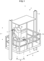
- FIG. 1 is a schematic diagram illustrating an exemplary work support system 1 of the present arrangement.
- the work support system 1 is a system for supporting work by a worker M.
- the worker M is an exemplary user.
- the work support system 1 supports work by the worker M in a passage.
- the passage has such a size that the worker M can work inside.
- the passage is, for example, an elevator hoistway 2, a tunnel in which an object such as a vehicle moves, or a sewer.
- the present arrangement describes an example in which the passage is the elevator hoistway 2.
- the elevator hoistway 2 is also referred to as an elevator shaft.
- the work support system 1 may be any system that supports work by the worker M, and its support target work is not limited to work in the passage such as the elevator hoistway 2.
- the work support system 1 includes a work support device 10.
- the work support device 10 is disposed in the elevator hoistway 2. In addition, in the exemplary form described in the present arrangement, the work support device 10 is disposed at a scaffold 3.
- the scaffold 3 is a cradle capable of accommodating the worker M.
- the scaffold 3 is a scaffold unit used in assembly of an elevator or the like, an elevator car, or a workbench.
- the scaffold 3 is detachably installed in the elevator hoistway 2 at maintenance or the like.
- the scaffold 3 disposed in the elevator hoistway 2 is supported by a displacement member disposed at a top part of the elevator hoistway 2 through a guide rail 4 and a cable.
- the scaffold 3 can be moved in a height direction Z along the guide rail 4 in the elevator hoistway 2 by the displacement member.
- the work support device 10 installed at the scaffold 3 is movable in the height direction Z in the elevator hoistway 2.
- the work support device 10 may be fixed in the elevator hoistway 2 or may be detachably installed at the scaffold 3 disposed in the elevator hoistway 2.
- the following description of the present arrangement assumes a case in which the worker M on the scaffold 3 disposed in the elevator hoistway 2 works in the elevator hoistway 2.
- the work support device 10 includes a control unit 20 and an arm unit 30.
- the control unit 20 controls actuation of the arm unit 30.
- the arm unit 30 is an assist mechanism for holding an object T.
- the arm unit 30 is a mechanism for supporting handling of the object T by the worker M.
- the object T is a target that the worker M contacts or holds at work.
- Examples of the object T include various equipment and tools such as an electric drill and an impact driver, and various attachment members and fixation members such as a bracket, a guide rail, a counter weight, and a component.
- the arm unit 30 is supported at the scaffold 3 by a support unit 5.
- the support unit 5 is provided to an outer frame member 3A of the scaffold 3 and movably supports the arm unit 30 along the outer frame member 3A.
- the support unit 5 movably supports the arm unit 30 in an extension direction (the direction of arrow Y) of the outer frame member 3A.
- the support unit 5 is, for example, a linear movement slider. Accordingly, the arm unit 30 has a compact configuration and has a movable range in which work by the worker M can be assisted without interference with a work area of the worker M.
- FIG. 2 is a schematic diagram of an example of the arm unit 30.
- the arm unit 30 includes a grasping part 32, a plurality of joint parts 34, and a plurality of link parts 36.
- the grasping part 32 is a mechanism that grasps the object T.
- the grasping part 32 includes a mechanism such as a pinching mechanism or an electromagnetic chuck to grasp the object T.
- Each link part 36 is a bar member.
- the arm unit 30 includes, as the link parts 36, a link part 36A and a link part 36B.
- the link parts 36 are actuatably coupled through the joint parts 34.
- Actuation means at least one of linear movement, rotation, and pivot movement.
- Actuatable means that at least one of linear movement, rotation, and pivot movement is possible.
- actuation means rotation
- actuatable means rotatable.
- the joint parts 34 are a coupling mechanism for coupling a pair of the link part 36A and the link part 36B and a pair of the link part 36B and the grasping part 32 in an actuatable manner.
- the arm unit 30 includes joint parts 34A to 34F as the joint parts 34.
- the joint part 34A and the joint part 34B couple the link part 36A on the support unit 5 in an actuatable manner.
- the joint part 34A is a horizontal rotation joint that is horizontally rotatable.
- the rotational axis of the joint part 34B orthogonally crosses the rotational axis of the joint part 34A.
- the joint part 34B is a vertical rotation joint that is vertically rotatable.
- the joint part 34C and the joint part 34D couple the link part 36A and the link part 36B with each other in an actuatable manner.
- the joint part 34C is a horizontal rotation joint.
- the rotational axis of the joint part 34D orthogonally crosses the rotational axis of the joint part 34C.
- the joint part 34D is a vertical rotation joint.
- the link part 36A has a parallel-link structure. With this configuration, the joint part 34C is horizontally rotatable irrespective of the rotation angles of the joint part 34A and the joint part 34B.
- the joint part 34E and the joint part 34F couple the link part 36B and the grasping part 32 with each other in an actuatable manner.
- the link part 36B and the grasping part 32 are coupled with each other through the joint part 34E and the joint part 34F.
- the joint part 34E is a horizontal rotation joint.
- the rotational axis of the joint part 34F orthogonally crosses the rotational axis of the joint part 34E.
- the joint part 34F is a vertical rotation joint.
- the link part 36B has a parallel-link structure. With this configuration, the joint part 34E is horizontally rotatable irrespective of the rotation angles of the joint part 34C and the joint part 34D.
- the arm unit 30 includes the joint parts 34.
- the worker M can easily intuitively understand motion of the arm unit 30 and safely perform work.
- At least one of the joint parts 34 is a horizontal rotation joint, and at least another one of the joint parts 34 is a vertical rotation joint.
- the joint part 34A, the joint part 34C, and the joint part 34E are horizontal rotation joints.
- the link part 36A and the link part 36B each have a parallel-link structure.
- the posture of each of the joint part 34A, the joint part 34C, and the joint part 34C is constantly horizontally maintained.
- the arm unit 30 of the present arrangement does not need to support gravitational force through actuation of these horizontal rotation joints.
- the arm unit 30 can achieve necessary torque reduction through these horizontal rotation joints when the object T held by the grasping part 32 is a heavy object having a weight equal to or heavier than a threshold value.
- the rotational axis of at least one of the joint parts 34 only needs to be orthogonal to the rotational axis of at least another one of the joint parts 34, and the rotational axes are not limited to the horizontal and vertical directions.
- the grasping part 32 and the link part 36B are coupled with each other through the joint part 34E and the joint part 34F.
- the joint part 34E is a horizontal rotation joint.
- the joint part 34F is a vertical rotation joint.
- the rotational axis of the joint part 34F orthogonally crosses the rotational axis of the joint part 34E.
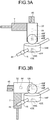
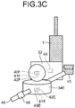
- FIGS. 3A to 3C are enlarged schematic diagrams of the grasping part 32.
- the grasping part 32 and the link part 36B are coupled with each other through the joint part 34E and the joint part 34F.
- the joint part 34F may be a rotational body that has a spherical shape and is rotatable by 360°.
- a handle part 48 to be grasped by the worker M during work is provided to the joint part 34E.
- the handle part 48 is a handle for the worker M to change the posture of the arm unit 30 or operate the position and posture of the object T grasped by the grasping part 32.
- the worker M can move the grasping part 32 in a desired direction by operating the handle part 48.
- An input unit 46 is provided to the handle part 48.
- the input unit 46 is an input mechanism for receiving various operation instructions from the worker M.
- the input unit 46 receives, for example, input of a switching instruction to perform switching between an automatic mode and a manual mode. Details of the automatic mode and the manual mode will be described later.
- Each joint part 34 of the arm unit 30 is provided with a drive unit 40, a brake unit 41, and an angle sensor 42.
- the joint part 34A to the joint part 34F are provided with drive unit 40A to drive unit 40F, brake unit 41A to brake unit 41F, and angle sensor 42A to angle sensor 42F, respectively.
- the joint part 34A to the joint part 34F are referred to as the joint parts 34.
- the drive unit 40A to the drive unit 40F are referred to as the drive units 40.
- the brake unit 41A to the brake unit 41F are referred to as the brake units 41.
- the angle sensor 42A to the angle sensor 42F are referred to as the angle sensors 42.
- the drive unit 40 actuates the corresponding joint part 34.
- the drive unit 40 is provided in at least one of the joint parts 34.
- the drive unit 40 is, for example, an actuator.
- the drive unit 40 is provided in each joint part 34 included in the arm unit 30.
- the drive unit 40 rotatably drives the joint part 34 provided with the drive unit 40.
- the drive unit 40 is driven under control of the control unit 20 to be described later (to be described later in detail).
- the drive unit 40 may be a well-known mechanism.
- the brake unit 41 restricts the actuation of the arm unit 30.
- the brake unit 41 is provided in at least one of the joint parts 34. In the exemplary form described in the present arrangement, the brake unit 41 is provided in each joint part 34 included in the arm unit 30.
- the brake unit 41 restricts actuation of the joint part 34 provided with the brake unit 41, thereby restricting actuation of the arm unit 30.
- "Restriction of actuation” means at least one of deceleration of the speed of actuation of the arm unit 30 and the joint part 34 and stopping of actuation of the arm unit 30 and the joint part 34.
- the brake unit 41 controls deceleration of the rotational speed of the joint part 34 or stopping of rotation of the joint part 34.
- the brake unit 41 may be a well-known braking mechanism.
- the angle sensor 42 is a sensor that measures a joint angle that is a variable amount (VA) as the rotation angle of the joint part 34.
- VA variable amount
- the angle sensor 42 is provided in each joint part 34.
- the angle sensor 42 measures, as the joint angle, the rotation angle of the joint part 34 provided with the angle sensor 42 based on a reference position.
- the reference position may be set in advance.
- the arm unit 30 also includes an obstacle sensing unit 43, a force sensor 44, and a target position detection unit 45.
- the obstacle sensing unit 43 senses any obstacle around the arm unit 30.
- An obstacle is an object that encumbers movement of the arm unit 30.
- An obstacle is, for example, a user such as the worker M, a wall in the elevator hoistway 2, or a member protruding from a wall.
- the obstacle sensing unit 43 is disposed on the surface of each of the link part 36A and the link part 36B.
- the obstacle sensing unit 43 may be provided to each joint part 34 and the grasping part 32.
- the obstacle sensing unit 43 is, for example, a well-known optical sensor but is not limited thereto.
- the force sensor 44 is a force sensor that detects pressure applied to the arm unit 30 and the direction of the pressure.
- the force sensor 44 is provided to the grasping part 32. Accordingly, the force sensor 44 detects pressure applied to the grasping part 32 and the direction of the pressure applied to the grasping part 32. In other words, the force sensor 44 detects the strength of force applied for moving the grasping part 32 and the direction of pressurization.
- the target position detection unit 45 is an exemplary detector.
- the target position detection unit 45 detects a target position.
- the target position is a target position at which the grasping part 32 or the object T grasped by the grasping part 32 is to be positioned.
- the target position detection unit 45 specifies the relative position of the grasping part 32 with respect to the target position.
- the target position detection unit 45 is, for example, an image capturing device that obtains captured image data through image capturing.
- the captured image data is also simply referred to as a captured image.
- FIG. 4 is a functional block diagram illustrating an exemplary functional configuration of the work support system 1 of the present arrangement.
- the work support system 1 includes the work support device 10 and an external device 11.
- the work support device 10 and the external device 11 are communicably connected with each other through a network N or the like.
- the external device 11 is a well-known computer such as a server device.
- the external device 11 is a server device such as a building information modeling (BIM) system that designs a work process or the like in advance.
- BIM building information modeling
- the work support device 10 includes the control unit 20 and the arm unit 30.
- the arm unit 30 includes the drive unit 40, the brake unit 41, the angle sensor 42, the obstacle sensing unit 43, the force sensor 44, the target position detection unit 45, and the input unit 46.
- the control unit 20 is communicably connected with each of the drive unit 40, the brake unit 41, the angle sensor 42, the obstacle sensing unit 43, the force sensor 44, the target position detection unit 45, and the input unit 46.
- the control unit 20 is, for example, a dedicated or general-purpose computer.
- the control unit 20 includes a processing unit 50, a storage unit 52, and a communication unit 54.
- the processing unit 50 is communicably connected with each of the communication unit 54 and the storage unit 52.
- the processing unit 50, the storage unit 52, the communication unit 54, the drive unit 40, the brake unit 41, the angle sensor 42, the obstacle sensing unit 43, the force sensor 44, the target position detection unit 45, and the input unit 46 are communicably connected with one another through a bus 56.
- the storage unit 52 stores therein various kinds of data.
- the storage unit 52 is, for example, a semiconductor memory device such as a random-access memory (RAM) or a flash memory, a hard disk, or an optical disc.
- the storage unit 52 may be a storage device provided outside the work support device 10.
- the storage unit 52 may be a storage medium.
- the storage medium may store or temporarily store therein computer programs and various kinds of information downloaded through a local area network (LAN), the Internet, or the like.
- the storage unit 52 may be formed of a plurality of storage media.
- At least one of the storage unit 52 and the processing unit 50 may be mounted on the external device 11 such as a server device connected with the network N.
- at least one of functional components (to be described later) included in the processing unit 50 may be mounted on the external device 11 such as a server device connected with the processing unit 50 through the network N.
- the processing unit 50 includes an acquisition unit 50A, a target angle derivation unit 50B, a movement direction derivation unit 50C, a spatial position derivation unit 50D, a reception unit 50E, a movement control unit 50F, a state determination unit 50G, and a brake control unit 50H.
- the state determination unit 50G includes a joint angle determination unit 501, a positioning determination unit 50J, an in-region operation determination unit 50K, and a collision determination unit 50L.
- At least one of the acquisition unit 50A, the target angle derivation unit 50B, the movement direction derivation unit 50C, the spatial position derivation unit 50D, the reception unit 50E, the movement control unit 50F, the state determination unit 50G, the brake control unit 50H, the joint angle determination unit 501, the positioning determination unit 50J, the in-region operation determination unit 50K, and the collision determination unit 50L is implemented by, for example, one or a plurality of processors.
- each of the above-described components may be implemented through execution of a computer program by a processor such as a central processing unit (CPU), in other words, by software.
- a processor such as a dedicated integrated circuit (IC), in other words, by hardware.
- IC dedicated integrated circuit
- each of the above-described components may be implemented by software and hardware in combination. When a plurality of processors are used, each processor may implement one of the components or may implement two or more of the components.
- the acquisition unit 50A acquires the joint angle of each joint part 34 from the corresponding angle sensor 42.
- the acquisition unit 50A also acquires an obstacle sensing result from the obstacle sensing unit 43.
- the acquisition unit 50A also acquires a result of detection of pressure applied to the grasping part 32 and the direction of the pressure from the force sensor 44.
- the acquisition unit 50A also acquires a result of detection of the target position from the target position detection unit 45.
- the acquisition unit 50A also acquires the target position.
- the acquisition unit 50A acquires the target position from the external device 11.
- the target position is set in advance based on, for example, an operation instruction through the input unit 46 by the user and stored in the storage unit 52.
- the acquisition unit 50A acquires the target position by reading the target position from the communication unit 54.
- the external device 11 may specify the target position for each work content or each work process. In this case, the acquisition unit 50A can acquire the target position from the external device 11 through the communication unit 54.
- the target angle derivation unit 50B derives a target angle that is the joint angle of each joint part 34 when the grasping part 32 is positioned at the target position.
- the target angle derivation unit 50B acquires the target position acquired by the acquisition unit 50A and information of the current position of the support unit 5 supporting the joint part 34A of the arm unit 30.
- the information of the current position of the support unit 5 is information indicating the spatial position of the support unit 5.
- the information of the current position of the support unit 5 is stored in, for example, the storage unit 52.
- the target angle derivation unit 50B derives the posture of the arm unit 30 when the grasping part 32 of the arm unit 30 is positioned at the target position by using a well-known method or the like.
- the target angle derivation unit 50B derives, as the target angle, the joint angle of each joint part 34 of the arm unit 30 in the derived posture.
- the target angle derivation unit 50B derives the target angle for each joint part 34 provided to the arm unit 30. Then, the target angle derivation unit 50B stores the derived target angle in the storage unit 52 in association with identification information of the corresponding joint part 34.
- the movement direction derivation unit 50C derives the movement direction of the arm unit 30. Specifically, the movement direction derivation unit 50C derives the movement direction of each of the grasping part 32, the link part 36B, and the joint parts 34 as components included in the arm unit 30 by using the result of detection of pressure applied to the grasping part 32 and the direction of the pressure, which are acquired from the force sensor 44, and the result of detection of the joint angle of each joint part 34, which is acquired from the corresponding angle sensor 42.
- the spatial position derivation unit 50D derives the spatial position of the arm unit 30.
- the spatial position of the arm unit 30 is information indicating the position and posture of each part included in the arm unit 30.
- the spatial position of the arm unit 30 is information indicating the position coordinates of each of the grasping part 32, the joint parts 34, and the link parts 36 as parts included in the arm unit 30, in the real space.
- the spatial position of the arm unit 30 may be information further including the position coordinates of the object T grasped by the grasping part 32.
- the spatial position derivation unit 50D derives the spatial position of the arm unit 30 by applying the angle of each joint part 34, which is acquired by the acquisition unit 50A, to a stereoscopic model of the arm unit 30 that is produced in advance.
- the spatial position derivation unit 50D may use another method to derive the spatial position of the arm unit 30.
- the arm unit 30 may be provided with a position sensor, and the spatial position derivation unit 50D may derive the spatial position of the arm unit 30 by using a result of detection by the position sensor.
- the reception unit 50E acquires, from the input unit 46, mode information indicating the automatic mode or the manual mode.
- An acquisition mode is a mode in which the arm unit 30 is manually moved by the worker M.
- the automatic mode is a mode in which the arm unit 30 is moved to the target position under control of the movement control unit 50F.
- the user operates the input unit 46 to input a switching instruction to perform switching from the manual mode to the automatic mode or from the automatic mode to the manual mode.
- the input unit 46 may be a switch for inputting switching between these modes.
- the reception unit 50E acquires the mode information indicating the manual mode by receiving a switching instruction to perform switching to the manual mode through the input unit 46.
- the reception unit 50E acquires the mode information indicating the automatic mode by receiving a switching instruction to perform switching to the automatic mode through the input unit 46.
- the movement control unit 50F moves the grasping part 32 of the arm unit 30 to the target position. Specifically, when having received a switching instruction to perform switching to the automatic mode, the movement control unit 50F starts controlling the drive unit 40 to move the grasping part 32 to the target position.
- the movement control unit 50F controls the drive unit 40 of each joint part 34 provided to the arm unit 30 so that the joint part 34 has the corresponding target angle derived by the target angle derivation unit 50B. Under the control of the movement control unit 50F, the grasping part 32 of the arm unit 30 starts moving toward the target position.
- the movement control unit 50F When having received a switching instruction to perform switching to the manual mode, the movement control unit 50F does not control the drive units 40. In this case, upon operation of the handle part 48 by the worker M, the grasping part 32 starts moving in a direction desired by the worker M, and the arm unit 30 starts moving.
- the state determination unit 50G determines the state of the arm unit 30.
- the state of the arm unit 30 is referred to as an arm state.
- the state determination unit 50G determines the arm state of the arm unit 30 during manual or automatic movement of the arm unit 30.
- the brake control unit 50H controls each brake unit 41 in accordance with the arm state to restrict actuation of the arm unit 30.
- the state determination unit 50G includes the joint angle determination unit 501, the positioning determination unit 50J, the in-region operation determination unit 50K, and the collision determination unit 50L.
- the joint angle determination unit 501 determines, as the arm state, whether at least one of the joint parts 34 has reached the target angle derived by the target angle derivation unit 50B. Specifically, the joint angle determination unit 501 determines whether the joint angle acquired from at least one of the angle sensors 42 has reached the target angle of the joint part 34 provided with that angle sensor 42.
- the brake control unit 50H restricts actuation of the arm unit 30 by restricting actuation of each joint part 34 determined to have reached the target angle.
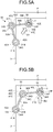
- FIGS. 5A to 5D are explanatory diagrams of exemplary restriction of actuation of the arm unit 30 in accordance with the joint angles of some joint parts 34. Examples of the state of the arm unit 30 are illustrated in a temporally sequential manner from FIGS. 5A to 5D .
- the target angle derivation unit 50B has derived a joint angle ⁇ as the target angle of the joint part 34A, a joint angle ⁇ as the target angle of the joint part 34C, and a joint angle ⁇ as the target angle of the joint part 34E.
- the worker M operates the handle part 48 and applies force in the direction of arrow D1 to the grasping part 32 to move the grasping part 32 toward a target position P.
- the joint angle determination unit 501 determines that the joint angle of the joint part 34A has reached the target angle. Accordingly, the brake control unit 50H restricts rotation of the joint part 34A by controlling the brake unit 41A of the joint part 34A.
- the joint angle determination unit 501 determines that the joint angle of the joint part 34C has reached the target angle. Accordingly, the brake control unit 50H restricts rotation of the joint part 34C by controlling the brake unit 41C of the joint part 34C.
- the joint angle determination unit 501 determines that the joint angle of the joint part 34E has reached the target angle. Accordingly, the brake control unit 50H restricts rotation of the joint part 34E by controlling the brake unit 41E of the joint part 34E.
- the joint angle determination unit 50I and the brake control unit 50H execute the same processing in the automatic mode as well in which the arm unit 30 automatically operates as the movement control unit 50F controls the drive unit 40 provided to each joint part 34 of the arm unit 30. Accordingly, the object T safely and easily arrives at the target position P in a case in which the arm unit 30 is driven under control of the movement control unit 50F to move the object T to the target position P, as well.
- the positioning determination unit 50J determines, as the arm state, whether the grasping part 32 is positioned at the target position P. In the present arrangement, the positioning determination unit 50J determines whether the grasping part 32 is positioned at the target position P based on a result of detection by the target position detection unit 45.
- the positioning determination unit 50J acquires a result of detection of the target position P by the target position detection unit 45 from the acquisition unit 50A.
- the target position detection unit 45 is, for example, an image capturing device.
- the positioning determination unit 50J specifies the target position P and the relative position of the grasping part 32 with respect to the target position P by performing image analysis of a captured image obtained through image capturing by the target position detection unit 45. The relative position detection may be performed on the target position detection unit 45 side. Then, the positioning determination unit 50J may determine, as the arm state, whether the relative position of the grasping part 32 with respect to the target position P coincides with the target position P.
- the brake control unit 50H may control each brake unit 41 to restrict actuation of the arm unit 30. Specifically, in the present arrangement, the brake control unit 50H may restrict rotation of the brake unit 41 of each joint part 34 provided to the arm unit 30.
- the accuracy of positioning the grasping part 32 and the object T grasped by the grasping part 32 to the target position P can be improved by controlling the brake control unit 50H in accordance with a result of the determination by the positioning determination unit 50J.
- the positioning determination unit 50J and the brake control unit 50H execute the same processing in the automatic mode as well in which the arm unit 30 automatically operates as the movement control unit 50F controls the drive unit 40 provided to each joint part 34 of the arm unit 30. Accordingly, the object T is accurately positioned to the target position P in a case in which the arm unit 30 is driven under control of the movement control unit 50F to move the object T to the target position P, as well.
- the in-region operation determination unit 50K determines, as the arm state, whether at least a partial region of the arm unit 30 is likely to protrude from the inside of a set spatial region to the outside of the set spatial region.
- the set spatial region is set in advance as a region in which the arm unit 30 can be safely actuated.
- FIG. 6 is an explanatory diagram of an exemplary set spatial region E.
- the set spatial region E is a region in which the arm unit 30 can be safely actuated when the arm unit 30 is actuated by the worker M working with the arm unit 30.
- the set spatial region E includes at least a part of the above-described movable range of the arm unit 30.
- Set-spatial-region information of the set spatial region E may be stored in the storage unit 52 in advance. The set-spatial-region information may be changeable as appropriate based on an operation instruction through the input unit 46 by the worker M, information received from the external device 11, or the like.
- the in-region operation determination unit 50K determines whether the arm unit 30 is likely to protrude to the outside of the set spatial region E based on the spatial position of the arm unit 30, the movement direction of the arm unit 30, and the set spatial region E of the set-spatial-region information.
- the in-region operation determination unit 50K acquires the spatial position of the arm unit 30, which is derived by the spatial position derivation unit 50D.
- the in-region operation determination unit 50K acquires the movement direction of the arm unit 30, which is derived by the movement direction derivation unit 50C.
- the in-region operation determination unit 50K acquires the set-spatial-region information of the set spatial region E from the storage unit 52.
- the in-region operation determination unit 50K predicts, by simulation, whether at least a partial region of the parts (the grasping part 32, the joint parts 34, and the link parts 36) included in the arm unit 30, which are indicated by the acquired spatial position of the arm unit 30, is positioned outside the set spatial region E when movement of the arm unit 30 in the movement direction is continued. Then, when a result of the prediction indicates that the region is positioned outside the set spatial region E, the in-region operation determination unit 50K determines that the arm unit 30 is likely to protrude to the outside of the set spatial region E.
- the in-region operation determination unit 50K determines that the arm unit 30 is not likely to protrude to the outside of the set spatial region E.
- the current position of at least a partial region of the parts (the grasping part 32, the joint parts 34, and the link parts 36) included in the arm unit 30 in the real space, which are indicated by the acquired spatial position of the arm unit 30, is positioned outside the set spatial region E in some cases.
- the in-region operation determination unit 50K may further determine that the arm unit 30 is likely to protrude to the outside of the set spatial region E.
- the brake control unit 50H controls the brake unit 41 to restrict actuation of the arm unit 30.
- the brake control unit 50H specifies a joint part 34 that contributes to positional movement of a region of each part included in the arm unit 30, which is determined to be likely to protrude to the outside of the set spatial region E by the in-region operation determination unit 50K. Then, the brake control unit 50H controls the corresponding brake unit 41 to restrict rotation of the specified joint part 34.
- FIGS. 7A and 7B are explanatory diagrams of exemplary actuation restriction in the set spatial region E. Examples of the state of the arm unit 30 are illustrated in a temporally sequential manner from FIGS. 7A to 7B .
- the joint part 34C and the joint part 34D are likely to be positioned outside the set spatial region E when movement of the arm unit 30 in the direction of the arrow D10 is continued as force in the direction of the arrow D10 is continuously applied.
- the in-region operation determination unit 50K determines that the joint part 34C and the joint part 34D of the arm unit 30 are likely to protrude to the outside of the set spatial region E based on the spatial position of the arm unit 30, which is derived by the spatial position derivation unit 50D, the movement direction of the arm unit 30, which is derived by the movement direction derivation unit 50C, and the set spatial region E of the set-spatial-region information.
- the brake control unit 50H specifies a joint part 34 that contributes to positional movement of the joint part 34C and the joint part 34D determined to be likely to protrude to the outside of the set spatial region E by the in-region operation determination unit 50K.
- the brake control unit 50H specifies the joint part 34A, the joint part 34C, and the joint part 34E.
- the brake control unit 50H controls the brake unit 41A, the brake unit 41C, and the brake unit 41E to restrict rotation of the specified joint parts 34A, 34C, and 34E.
- the brake control unit 50H controls the brake unit 41 based on a result of determination by the in-region operation determination unit 50K, thereby preventing at least a partial region of the arm unit 30 from protruding to the outside of the set spatial region E.
- the in-region operation determination unit 50K determines whether at least a partial region of the arm unit 30 is likely to protrude to the outside of the set spatial region E as movement in the direction of the arrow D12 is continued.
- the brake control unit 50H cancels rotation restriction on the joint part 34 rotation of which is restricted. Accordingly, as illustrated in FIG. 7B , the worker M can move the grasping part 32 in a direction toward the object T by continuously applying force in the direction of the arrow D12 to the grasping part 32.
- the in-region operation determination unit 50K and the brake control unit 50H execute the same processing in the automatic mode as well in which the arm unit 30 automatically operates as the movement control unit 50F controls the drive unit 40 provided to each joint part 34 of the arm unit 30. Accordingly, the object T safely and easily arrives at the target position P in a case in which the arm unit 30 is driven under control of the movement control unit 50F to move the object T to the target position P, as well.
- the collision determination unit 50L determines, as the arm state, whether at least a partial region of the arm unit 30 is in a close state in which the partial region of the arm unit 30 is close to an obstacle, based on a result of sensing by the obstacle sensing unit 43.
- the close state means a state in which the distance between at least a partial region of the arm unit 30 and the obstacle is equal to or shorter than a predetermined threshold value.
- the close state may also mean that a state in which the distance between the arm unit 30 and the obstacle is likely to become equal to or shorter than the threshold value as the arm unit 30 continuously moves. In the example described in the present arrangement, the close state means that the distance between the arm unit 30 and the obstacle is likely to become equal to or shorter than the threshold value as the arm unit 30 continuously moves.
- the threshold value may be set in advance to be a value that can avoid a state in which the arm unit 30 and the arm unit 30 become close to each other enough to compromise safety and the close state is caused by changing the movement direction of the arm unit 30.
- the collision determination unit 50L determines whether at least a partial region of the arm unit 30 is in the close state based on a result of sensing by the obstacle sensing unit 43, and the movement direction of the arm unit 30, which is derived from a result of sensing by the force sensor 44.
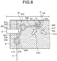
- FIG. 8 is an explanatory diagram of exemplary restriction of actuation of the arm unit 30 in the close state.
- the distance between the link part 36A and an obstacle B is likely to become equal to or shorter than the above-described threshold value as movement of the arm unit 30 in the direction of the arrow D13 is continued through continuous application of force in the direction of the arrow D13.
- the in-region operation determination unit 50K determines that at least a partial region of the arm unit 30 is in the close state based on the movement direction of the arm unit 30, which is derived from a result of sensing by the force sensor 44, and a result of sensing by the obstacle sensing unit 43.
- the brake control unit 50H controls the brake unit 41 to restrict actuation of the arm unit 30.
- the brake control unit 50H specifies a joint part 34 that contributes to positional movement of a part of the arm unit 30, which is determined to be in the close state by the collision determination unit 50L. For example, assume that the brake control unit 50H specifies the joint part 34A and the joint part 34C. In this case, the brake control unit 50H controls the brake unit 41A and the brake unit 41C to restrict rotation of the specified joint parts 34A and 34C.
- the brake control unit 50H controls the brake unit 41 based on a result of determination by the collision determination unit 50L, thereby preventing at least a partial region of the arm unit 30 from colliding with the obstacle B.
- the collision determination unit 50L determines whether the arm unit 30 becomes close to the obstacle B as movement in the direction of the arrow D14 is continued.
- the brake control unit 50H cancels rotation restriction on the joint part 34 rotation of which is restricted. Accordingly, the worker M can move the grasping part 32 in a direction toward the object T while avoiding the obstacle B by continuously applying force in the direction of the arrow D14 to the grasping part 32.
- the collision determination unit 50L and the brake control unit 50H execute the same processing in the automatic mode as well in which the arm unit 30 automatically operates as the movement control unit 50F controls the drive unit 40 provided to each joint part 34 of the arm unit 30. Accordingly, the object T safely and easily arrives at the target position P in a case in which the arm unit 30 is driven under control of the movement control unit 50F to move the object T to the target position P, as well.
- FIG. 9 is a flowchart illustrating an exemplary flow of the work support processing executed by the work support device 10.
- the reception unit 50E receives mode information indicating the automatic mode or the manual mode from the input unit 46 (step S100).
- the reception unit 50E stores the acquired mode information in the storage unit 52 (step S102).
- the acquisition unit 50A acquires a target position P from the storage unit 52 (step S104).
- the target angle derivation unit 50B derives, by using the target position P acquired at step S104, a target angle that is the joint angle of each joint part 34 when the grasping part 32 is positioned at the target position P (step S106).
- the target angle derivation unit 50B stores the target angle derived at step S106 in the storage unit 52 in association with identification information of the corresponding joint part 34 (step S108).
- step S110 movement of the arm unit 30 is started (step S110).
- the mode information stored at step S102 is information indicating the manual mode
- movement of the arm unit 30 is disclosed as movement of the grasping part 32 toward the target position P is started through operation of the handle part 48 by the worker M.
- the mode information stored at step S102 is information indicating the automatic mode
- movement of the arm unit 30 is disclosed so that the grasping part 32 approaches the target position P as the drive unit 40 is controlled by the movement control unit 50F.
- the state determination unit 50G may determine that movement of the arm unit 30 is started and may execute processing to be described later when a result of detection of the joint angle of the joint part 34, which is acquired from the corresponding angle sensor 42 by the acquisition unit 50A, is a detection result indicating temporal change of the joint angle.
- the joint angle determination unit 50I determines whether at least one of the joint parts 34 has reached the target angle derived at step S106 (step S112). At step S112, the negative determination (No at step S112) is repeated until the positive determination is obtained (Yes at step S112). When the positive determination is obtained at step S112 (Yes at step S112), the process proceeds to step S114.
- step S114 the brake control unit 50H restricts actuation of the joint part 34 determined to have reached the target angle at step S112 (step S114).
- the joint angle determination unit 50I determines whether all joint parts 34 provided to the arm unit 30 each have reached the corresponding target angle derived at step S106 (step S116).
- the process returns to the above-described step S112.
- the process proceeds to step S118.
- the positioning determination unit 50J specifies the target position P and the relative position of the grasping part 32 with respect to the target position P by performing image analysis of a captured image obtained through image capturing by the target position detection unit 45 (step S118). Then, the positioning determination unit 50J determines whether the relative position of the grasping part 32 with respect to the target position P coincides with the target position P by using a result of the specification at step S118 (step S120).
- step S120 When the negative determination is obtained at step S120 (No at step S120), the process proceeds to step S122.
- step S122 the brake control unit 50H cancels actuation restriction on all joint parts 34 provided to the arm unit 30 (step S122). Then, the process returns to the above-described step S112.
- step S120 When the positive determination is obtained at step S120 (Yes at step S120), the process proceeds to step S124.
- the brake control unit 50H restricts actuation of the brake unit 41 of each joint part 34 provided to the arm unit 30 (step S124). Then, the present routine is ended.
- the brake control unit 50H may cancel actuation restriction on all joint parts 34 provided to the arm unit 30 after work by the worker M at the target position P is ended. In this case, the brake control unit 50H may execute the following processing.
- a work direction at the target position P is set in advance.
- the object T grasped by the grasping part 32 is an electric drill.
- the work direction is, for example, a direction in which a hole is formed in a wall by the electric drill.
- the brake control unit 50H When having determined that pressure in the above-described work direction is applied to the grasping part 32 based on a result of detection of pressure applied to the grasping part 32 and the direction of the pressure, which are acquired from the force sensor 44, the brake control unit 50H continues the actuation restriction processing at the above-described step S124.
- the brake control unit 50H determines that work by the worker M at the target position P is ended. Then, having determined that the work is ended, the brake control unit 50H may cancel actuation restriction on all joint parts 34 provided to the arm unit 30.
- interrupt processing executed by the work support device 10 during the work support processing illustrated in FIG. 9 will be described below.
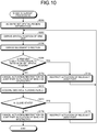
- FIG. 10 is a flowchart illustrating an exemplary flow of the interrupt processing executed by the work support device 10.
- the work support device 10 executes the interrupt processing illustrated in FIG. 10 during the processing at steps S112 to S124 illustrated in FIG. 9 .
- the acquisition unit 50A acquires the set-spatial-region information of the set spatial region E from the storage unit 52 (step S200).
- the spatial position derivation unit 50D derives the spatial position of the arm unit 30 by applying the angle of each joint part 34, which is acquired by the acquisition unit 50A, to a stereoscopic model of the arm unit 30 that is produced in advance (step S202).
- the movement direction derivation unit 50C derives the movement direction of each of the grasping part 32, the link part 36B, and the joint parts 34 as components included in the arm unit 30 based on a result of detection of pressure applied to the grasping part 32 and the direction of the pressure, which is acquired from the force sensor 44, and a result of detection of the joint angle of each joint part 34, which is acquired from the corresponding angle sensor 42 (step S204).
- the in-region operation determination unit 50K determines whether the arm unit 30 is likely to protrude to the outside of the set spatial region E based on the spatial position of the arm unit 30 derived at step S202, the movement direction of the arm unit 30 derived at step S204, and the set spatial region E of the set-spatial-region information acquired at step S200 (step S206).
- step S206 When the arm unit 30 is determined to be likely to protrude to the outside of the set spatial region E (Yes at step S206), the process proceeds to step S208.
- the brake control unit 50H specifies a joint part 34 that contributes to positional movement of a region of each part included in the arm unit 30, which is determined to be likely to protrude to the outside of the set spatial region E at step S206. Then, the brake control unit 50H controls the corresponding brake unit 41 to restrict actuation of the specified joint part 34 (step S208). Then, the process returns to the above-described step S202.
- step S210 When the arm unit 30 is determined not to likely to protrude to the set spatial region E at step S206 (No at step S206), the process proceeds to step S210.
- step S210 the brake control unit 50H cancels actuation restriction on the joint part 34 actuation of which is restricted (step S210).
- the collision determination unit 50L acquires an obstacle sensing result from the obstacle sensing unit 43 (step S212). Then, the collision determination unit 50L determines whether the arm unit 30 is close to the obstacle B based on the obstacle sensing result and the movement direction of the arm unit 30, which is derived at step S204 (step S214).
- step S216 the brake control unit 50H specifies a joint part 34 that contributes to positional movement of a part of the arm unit 30 determined to be in the close state by the collision determination unit 50L. Then, the brake control unit 50H controls the corresponding brake unit to restrict actuation of the specified joint part (step S216). Then, the process returns to the above-described step S202.
- step S214 When it is determined that the arm unit 30 is not close to the obstacle B (No at step S214), the process proceeds to step S218.
- the work support device 10 of the present arrangement includes the arm unit 30, each brake unit 41, the state determination unit 50G, and the brake control unit 50H.
- the arm unit 30 includes the grasping part 32 grasping the object T, the joint parts 34, and the link parts 36 actuatably coupled through the joint parts 34.
- the brake unit 41 is provided to at least one of the joint parts 34 to restrict actuation of the arm unit 30.
- the state determination unit 50G determines the arm state of the arm unit 30.
- the brake control unit 50H controls the brake unit 41 to restrict actuation of the arm unit 30 in accordance with the arm state.
- the work support device 10 of the present arrangement controls the brake unit 41 provided to the arm unit 30 in accordance with the arm state of the arm unit 30, to restrict actuation of the arm unit 30.
- the work support device 10 of the present arrangement can achieve improved work support.
- control unit 20 in the work support device 10 of the above-described arrangement will be described below.
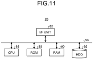
- FIG. 11 is a diagram illustrating an exemplary hardware configuration of the control unit 20.
- the control unit 20 has a hardware configuration of a typical computer including a control device such as a CPU 86, storage devices such as a read-only memory (ROM) 88, a random-access memory (RAM) 90, and a hard disk drive (HDD) 92, an I/F unit 82 that is an interface for various devices, and a bus 96 connecting the components.
- a control device such as a CPU 86
- storage devices such as a read-only memory (ROM) 88, a random-access memory (RAM) 90, and a hard disk drive (HDD) 92
- I/F unit 82 that is an interface for various devices
- a bus 96 connecting the components.
- each of the above-described components is implemented on the computer when the CPU 86 reads a computer program from the ROM 88 onto the RAM 90 and executes the computer program.
- a computer program for executing the above-described processing executed by the control unit 20 of the above-described arrangement may be stored in the HDD 92.
- the computer program for executing each above-described processing executed by the control unit 20 of the above-described arrangement may be incorporated in the ROM 88 in advance and provided.
- the computer program for executing the above-described processing executed by the control unit 20 of the above-described arrangement may be stored in a computer-readable storage medium such as a CD-ROM, a CD-R, a memory card, a digital versatile disc (DVD), or a flexible disk (FD) as a file in an installable or executable format to be provided as a computer program product.
- the computer program for executing the above-described processing executed by the control unit 20 of the above-described arrangement may be stored on a computer connected with a network such as the Internet, and downloaded and provided through the network.
- the computer program for executing the above-described processing executed by the control unit 20 of the above-described arrangement may be provided or distributed through a network such as the Internet.
Landscapes
- Engineering & Computer Science (AREA)
- Mechanical Engineering (AREA)
- Robotics (AREA)
- General Engineering & Computer Science (AREA)
- Human Computer Interaction (AREA)
- Physics & Mathematics (AREA)
- General Physics & Mathematics (AREA)
- Automation & Control Theory (AREA)
- Manufacturing & Machinery (AREA)
- Manipulator (AREA)
- Lift-Guide Devices, And Elevator Ropes And Cables (AREA)
Abstract
Description
- Arrangements described herein relate generally to a work support device, a work support method, a computer program product, and a work support system.
- Devices that support work such as assembly work and installation work of a heavy object have been known. For example, in a disclosed configuration, a workpiece weight for balancing with the weight of a workpiece as a heavy object is provided at an end part of an arm that supports the workpiece. An example of conventional technology is described in Japanese Patent Application Laid-open No.
6591641 - However, by the conventional technology, there are cases where a workpiece weight disturbs the work, and it has been difficult to support work while avoiding various interferers in a given region such as the inside of a passage. In other words, by the conventional technology, there are difficult cases of achieving improved work support.
-
-
FIG. 1 is a schematic diagram of a work support system according to an arrangement; -
FIG. 2 is a schematic diagram of an arm unit according to the arrangement; -
FIG. 3A is an enlarged schematic diagram of a grasping part according to the arrangement; -
FIG. 3B is an enlarged schematic diagram of the grasping part according to the arrangement; -
FIG. 3C is an enlarged schematic diagram of the grasping part according to the arrangement; -
FIG. 4 is a functional block diagram of the work support system according to the arrangement; -
FIG. 5A is an explanatory diagram of actuation restriction of the arm unit in accordance with joint angles of joint parts according to the arrangement; -
FIG. 5B is an explanatory diagram of actuation restriction of the arm unit in accordance with the joint angles of the joint parts according to the arrangement; -
FIG. 5C is an explanatory diagram of actuation restriction of the arm unit in accordance with the joint angles of the joint parts according to the arrangement; -
FIG. 5D is an explanatory diagram of actuation restriction of the arm unit in accordance with the joint angles of the joint parts according to the arrangement; -
FIG. 6 is an explanatory diagram of a set spatial region according to the arrangement; -
FIG. 7A is an explanatory diagram of actuation restriction of the set spatial region according to the arrangement; -
FIG. 7B is an explanatory diagram of actuation restriction of the set spatial region according to the arrangement; -
FIG. 8 is an explanatory diagram of actuation restriction of the arm unit in a close state according to the arrangement; -
FIG. 9 is a flowchart illustrating the flow of work support processing according to the arrangement; -
FIG. 10 is a flowchart illustrating the flow of interrupt processing according to the arrangement; and -
FIG. 11 is a diagram illustrating a hardware configuration according to the arrangement. - The following describes a work support device, a work support method, a computer program product, and a work support system in detail with reference to the accompanying drawings.
-
FIG. 1 is a schematic diagram illustrating an exemplarywork support system 1 of the present arrangement. - The
work support system 1 is a system for supporting work by a worker M. The worker M is an exemplary user. For example, thework support system 1 supports work by the worker M in a passage. - The passage has such a size that the worker M can work inside. The passage is, for example, an
elevator hoistway 2, a tunnel in which an object such as a vehicle moves, or a sewer. The present arrangement describes an example in which the passage is theelevator hoistway 2. Theelevator hoistway 2 is also referred to as an elevator shaft. Thework support system 1 may be any system that supports work by the worker M, and its support target work is not limited to work in the passage such as theelevator hoistway 2. - The
work support system 1 includes awork support device 10. - In the exemplary form described in the present arrangement, the
work support device 10 is disposed in theelevator hoistway 2. In addition, in the exemplary form described in the present arrangement, thework support device 10 is disposed at ascaffold 3. - The
scaffold 3 is a cradle capable of accommodating the worker M. For example, thescaffold 3 is a scaffold unit used in assembly of an elevator or the like, an elevator car, or a workbench. Thescaffold 3 is detachably installed in theelevator hoistway 2 at maintenance or the like. Thescaffold 3 disposed in theelevator hoistway 2 is supported by a displacement member disposed at a top part of theelevator hoistway 2 through aguide rail 4 and a cable. Thescaffold 3 can be moved in a height direction Z along theguide rail 4 in theelevator hoistway 2 by the displacement member. - The
work support device 10 installed at thescaffold 3 is movable in the height direction Z in theelevator hoistway 2. Alternatively, thework support device 10 may be fixed in theelevator hoistway 2 or may be detachably installed at thescaffold 3 disposed in theelevator hoistway 2. The following description of the present arrangement assumes a case in which the worker M on thescaffold 3 disposed in theelevator hoistway 2 works in theelevator hoistway 2. - The
work support device 10 includes acontrol unit 20 and anarm unit 30. - The
control unit 20 controls actuation of thearm unit 30. Thearm unit 30 is an assist mechanism for holding an object T. In other words, thearm unit 30 is a mechanism for supporting handling of the object T by the worker M. - The object T is a target that the worker M contacts or holds at work. Examples of the object T include various equipment and tools such as an electric drill and an impact driver, and various attachment members and fixation members such as a bracket, a guide rail, a counter weight, and a component.
- In the present arrangement, the
arm unit 30 is supported at thescaffold 3 by asupport unit 5. Thesupport unit 5 is provided to anouter frame member 3A of thescaffold 3 and movably supports thearm unit 30 along theouter frame member 3A. For example, thesupport unit 5 movably supports thearm unit 30 in an extension direction (the direction of arrow Y) of theouter frame member 3A. Thesupport unit 5 is, for example, a linear movement slider. Accordingly, thearm unit 30 has a compact configuration and has a movable range in which work by the worker M can be assisted without interference with a work area of the worker M. -
FIG. 2 is a schematic diagram of an example of thearm unit 30. - The
arm unit 30 includes agrasping part 32, a plurality ofjoint parts 34, and a plurality oflink parts 36. - The grasping
part 32 is a mechanism that grasps the object T. The graspingpart 32 includes a mechanism such as a pinching mechanism or an electromagnetic chuck to grasp the object T. - Each
link part 36 is a bar member. In the present arrangement, thearm unit 30 includes, as thelink parts 36, alink part 36A and alink part 36B. Thelink parts 36 are actuatably coupled through thejoint parts 34. - "Actuation" means at least one of linear movement, rotation, and pivot movement. "Actuatable" means that at least one of linear movement, rotation, and pivot movement is possible. In an exemplary form described in the present arrangement, "actuation" means rotation, and "actuatable" means rotatable.
- The
joint parts 34 are a coupling mechanism for coupling a pair of thelink part 36A and thelink part 36B and a pair of thelink part 36B and the graspingpart 32 in an actuatable manner. In the present arrangement, thearm unit 30 includesjoint parts 34A to 34F as thejoint parts 34. - The
joint part 34A and thejoint part 34B couple thelink part 36A on thesupport unit 5 in an actuatable manner. In the present arrangement, thejoint part 34A is a horizontal rotation joint that is horizontally rotatable. The rotational axis of thejoint part 34B orthogonally crosses the rotational axis of thejoint part 34A. Thejoint part 34B is a vertical rotation joint that is vertically rotatable. - The
joint part 34C and thejoint part 34D couple thelink part 36A and thelink part 36B with each other in an actuatable manner. In the present arrangement, thejoint part 34C is a horizontal rotation joint. The rotational axis of thejoint part 34D orthogonally crosses the rotational axis of thejoint part 34C. Thejoint part 34D is a vertical rotation joint. Thelink part 36A has a parallel-link structure. With this configuration, thejoint part 34C is horizontally rotatable irrespective of the rotation angles of thejoint part 34A and thejoint part 34B. - The
joint part 34E and thejoint part 34F couple thelink part 36B and the graspingpart 32 with each other in an actuatable manner. In other words, thelink part 36B and the graspingpart 32 are coupled with each other through thejoint part 34E and thejoint part 34F. In the present arrangement, thejoint part 34E is a horizontal rotation joint. The rotational axis of thejoint part 34F orthogonally crosses the rotational axis of thejoint part 34E. Thejoint part 34F is a vertical rotation joint. Thelink part 36B has a parallel-link structure. With this configuration, thejoint part 34E is horizontally rotatable irrespective of the rotation angles of thejoint part 34C and thejoint part 34D. - As described above, the
arm unit 30 includes thejoint parts 34. Thus, it is advantageous that the worker M can easily intuitively understand motion of thearm unit 30 and safely perform work. - In addition, as described above, at least one of the
joint parts 34 is a horizontal rotation joint, and at least another one of thejoint parts 34 is a vertical rotation joint. Specifically, in the present arrangement, thejoint part 34A, thejoint part 34C, and thejoint part 34E are horizontal rotation joints. Thelink part 36A and thelink part 36B each have a parallel-link structure. - With this configuration, the posture of each of the
joint part 34A, thejoint part 34C, and thejoint part 34C is constantly horizontally maintained. Thus, thearm unit 30 of the present arrangement does not need to support gravitational force through actuation of these horizontal rotation joints. In addition, thearm unit 30 can achieve necessary torque reduction through these horizontal rotation joints when the object T held by the graspingpart 32 is a heavy object having a weight equal to or heavier than a threshold value. Moreover, it is possible to reduce the size of the mechanism of thearm unit 30 and the electrical driving power of thearm unit 30. - In the
arm unit 30, the rotational axis of at least one of thejoint parts 34 only needs to be orthogonal to the rotational axis of at least another one of thejoint parts 34, and the rotational axes are not limited to the horizontal and vertical directions. - The grasping
part 32 and thelink part 36B are coupled with each other through thejoint part 34E and thejoint part 34F. Thejoint part 34E is a horizontal rotation joint. Thejoint part 34F is a vertical rotation joint. The rotational axis of thejoint part 34F orthogonally crosses the rotational axis of thejoint part 34E. -
FIGS. 3A to 3C are enlarged schematic diagrams of the graspingpart 32. As described above, the graspingpart 32 and thelink part 36B are coupled with each other through thejoint part 34E and thejoint part 34F. Thus, the posture of the object T held by the graspingpart 32 is easily changed upward, downward, rightward, and leftward about the axes (refer toFIGS. 3A to 3C ). Thejoint part 34F may be a rotational body that has a spherical shape and is rotatable by 360°. - A
handle part 48 to be grasped by the worker M during work is provided to thejoint part 34E. Thehandle part 48 is a handle for the worker M to change the posture of thearm unit 30 or operate the position and posture of the object T grasped by the graspingpart 32. The worker M can move the graspingpart 32 in a desired direction by operating thehandle part 48. - An
input unit 46 is provided to thehandle part 48. Theinput unit 46 is an input mechanism for receiving various operation instructions from the worker M. In the present arrangement, theinput unit 46 receives, for example, input of a switching instruction to perform switching between an automatic mode and a manual mode. Details of the automatic mode and the manual mode will be described later. - The description continues with reference back to
FIG. 2 . - Each
joint part 34 of thearm unit 30 is provided with adrive unit 40, abrake unit 41, and anangle sensor 42. - Specifically, the
joint part 34A to thejoint part 34F are provided withdrive unit 40A to driveunit 40F,brake unit 41A to brakeunit 41F, andangle sensor 42A toangle sensor 42F, respectively. When collectively described, thejoint part 34A to thejoint part 34F are referred to as thejoint parts 34. When collectively described, thedrive unit 40A to thedrive unit 40F are referred to as thedrive units 40. When collectively described, thebrake unit 41A to thebrake unit 41F are referred to as thebrake units 41. When collectively described, theangle sensor 42A to theangle sensor 42F are referred to as theangle sensors 42. - The
drive unit 40 actuates the correspondingjoint part 34. Thedrive unit 40 is provided in at least one of thejoint parts 34. Thedrive unit 40 is, for example, an actuator. In the exemplary form described in the present arrangement, thedrive unit 40 is provided in eachjoint part 34 included in thearm unit 30. In the present arrangement, thedrive unit 40 rotatably drives thejoint part 34 provided with thedrive unit 40. Thedrive unit 40 is driven under control of thecontrol unit 20 to be described later (to be described later in detail). Thedrive unit 40 may be a well-known mechanism. - The
brake unit 41 restricts the actuation of thearm unit 30. Thebrake unit 41 is provided in at least one of thejoint parts 34. In the exemplary form described in the present arrangement, thebrake unit 41 is provided in eachjoint part 34 included in thearm unit 30. Thebrake unit 41 restricts actuation of thejoint part 34 provided with thebrake unit 41, thereby restricting actuation of thearm unit 30. "Restriction of actuation" means at least one of deceleration of the speed of actuation of thearm unit 30 and thejoint part 34 and stopping of actuation of thearm unit 30 and thejoint part 34. In other words, in the present arrangement, thebrake unit 41 controls deceleration of the rotational speed of thejoint part 34 or stopping of rotation of thejoint part 34. Thebrake unit 41 may be a well-known braking mechanism. - The
angle sensor 42 is a sensor that measures a joint angle that is a variable amount (VA) as the rotation angle of thejoint part 34. In the present arrangement, theangle sensor 42 is provided in eachjoint part 34. Theangle sensor 42 measures, as the joint angle, the rotation angle of thejoint part 34 provided with theangle sensor 42 based on a reference position. The reference position may be set in advance. - The
arm unit 30 also includes anobstacle sensing unit 43, aforce sensor 44, and a targetposition detection unit 45. - The
obstacle sensing unit 43 senses any obstacle around thearm unit 30. An obstacle is an object that encumbers movement of thearm unit 30. An obstacle is, for example, a user such as the worker M, a wall in theelevator hoistway 2, or a member protruding from a wall. - In the exemplary form described in the present arrangement, the
obstacle sensing unit 43 is disposed on the surface of each of thelink part 36A and thelink part 36B. Theobstacle sensing unit 43 may be provided to eachjoint part 34 and the graspingpart 32. Theobstacle sensing unit 43 is, for example, a well-known optical sensor but is not limited thereto. - The
force sensor 44 is a force sensor that detects pressure applied to thearm unit 30 and the direction of the pressure. In the present arrangement, theforce sensor 44 is provided to the graspingpart 32. Accordingly, theforce sensor 44 detects pressure applied to the graspingpart 32 and the direction of the pressure applied to the graspingpart 32. In other words, theforce sensor 44 detects the strength of force applied for moving the graspingpart 32 and the direction of pressurization. - The target
position detection unit 45 is an exemplary detector. The targetposition detection unit 45 detects a target position. - The target position is a target position at which the grasping
part 32 or the object T grasped by the graspingpart 32 is to be positioned. In the present arrangement, the targetposition detection unit 45 specifies the relative position of the graspingpart 32 with respect to the target position. The targetposition detection unit 45 is, for example, an image capturing device that obtains captured image data through image capturing. Hereinafter, the captured image data is also simply referred to as a captured image. - The following describes a functional configuration of the
work support system 1 of the present arrangement. -
FIG. 4 is a functional block diagram illustrating an exemplary functional configuration of thework support system 1 of the present arrangement. - The
work support system 1 includes thework support device 10 and an external device 11. Thework support device 10 and the external device 11 are communicably connected with each other through a network N or the like. - The external device 11 is a well-known computer such as a server device. For example, the external device 11 is a server device such as a building information modeling (BIM) system that designs a work process or the like in advance.
- The
work support device 10 includes thecontrol unit 20 and thearm unit 30. Thearm unit 30 includes thedrive unit 40, thebrake unit 41, theangle sensor 42, theobstacle sensing unit 43, theforce sensor 44, the targetposition detection unit 45, and theinput unit 46. Thecontrol unit 20 is communicably connected with each of thedrive unit 40, thebrake unit 41, theangle sensor 42, theobstacle sensing unit 43, theforce sensor 44, the targetposition detection unit 45, and theinput unit 46. - The
control unit 20 is, for example, a dedicated or general-purpose computer. Thecontrol unit 20 includes aprocessing unit 50, a storage unit 52, and acommunication unit 54. Theprocessing unit 50 is communicably connected with each of thecommunication unit 54 and the storage unit 52. - Specifically, the
processing unit 50, the storage unit 52, thecommunication unit 54, thedrive unit 40, thebrake unit 41, theangle sensor 42, theobstacle sensing unit 43, theforce sensor 44, the targetposition detection unit 45, and theinput unit 46 are communicably connected with one another through a bus 56. - The storage unit 52 stores therein various kinds of data. The storage unit 52 is, for example, a semiconductor memory device such as a random-access memory (RAM) or a flash memory, a hard disk, or an optical disc. The storage unit 52 may be a storage device provided outside the
work support device 10. Alternatively, the storage unit 52 may be a storage medium. Specifically, the storage medium may store or temporarily store therein computer programs and various kinds of information downloaded through a local area network (LAN), the Internet, or the like. The storage unit 52 may be formed of a plurality of storage media. - At least one of the storage unit 52 and the
processing unit 50 may be mounted on the external device 11 such as a server device connected with the network N. In addition, at least one of functional components (to be described later) included in theprocessing unit 50 may be mounted on the external device 11 such as a server device connected with theprocessing unit 50 through the network N. - The
processing unit 50 includes anacquisition unit 50A, a targetangle derivation unit 50B, a movementdirection derivation unit 50C, a spatialposition derivation unit 50D, areception unit 50E, amovement control unit 50F, astate determination unit 50G, and abrake control unit 50H. Thestate determination unit 50G includes a jointangle determination unit 501, apositioning determination unit 50J, an in-regionoperation determination unit 50K, and acollision determination unit 50L. - At least one of the
acquisition unit 50A, the targetangle derivation unit 50B, the movementdirection derivation unit 50C, the spatialposition derivation unit 50D, thereception unit 50E, themovement control unit 50F, thestate determination unit 50G, thebrake control unit 50H, the jointangle determination unit 501, thepositioning determination unit 50J, the in-regionoperation determination unit 50K, and thecollision determination unit 50L is implemented by, for example, one or a plurality of processors. For example, each of the above-described components may be implemented through execution of a computer program by a processor such as a central processing unit (CPU), in other words, by software. Each of the above-described components may be implemented by a processor such as a dedicated integrated circuit (IC), in other words, by hardware. Each of the above-described components may be implemented by software and hardware in combination. When a plurality of processors are used, each processor may implement one of the components or may implement two or more of the components. - The
acquisition unit 50A acquires the joint angle of eachjoint part 34 from thecorresponding angle sensor 42. Theacquisition unit 50A also acquires an obstacle sensing result from theobstacle sensing unit 43. Theacquisition unit 50A also acquires a result of detection of pressure applied to the graspingpart 32 and the direction of the pressure from theforce sensor 44. Theacquisition unit 50A also acquires a result of detection of the target position from the targetposition detection unit 45. - The
acquisition unit 50A also acquires the target position. Theacquisition unit 50A acquires the target position from the external device 11. The target position is set in advance based on, for example, an operation instruction through theinput unit 46 by the user and stored in the storage unit 52. Theacquisition unit 50A acquires the target position by reading the target position from thecommunication unit 54. The external device 11 may specify the target position for each work content or each work process. In this case, theacquisition unit 50A can acquire the target position from the external device 11 through thecommunication unit 54. - The target
angle derivation unit 50B derives a target angle that is the joint angle of eachjoint part 34 when the graspingpart 32 is positioned at the target position. - The target
angle derivation unit 50B acquires the target position acquired by theacquisition unit 50A and information of the current position of thesupport unit 5 supporting thejoint part 34A of thearm unit 30. The information of the current position of thesupport unit 5 is information indicating the spatial position of thesupport unit 5. The information of the current position of thesupport unit 5 is stored in, for example, the storage unit 52. Then, the targetangle derivation unit 50B derives the posture of thearm unit 30 when the graspingpart 32 of thearm unit 30 is positioned at the target position by using a well-known method or the like. Then, the targetangle derivation unit 50B derives, as the target angle, the joint angle of eachjoint part 34 of thearm unit 30 in the derived posture. In other words, the targetangle derivation unit 50B derives the target angle for eachjoint part 34 provided to thearm unit 30. Then, the targetangle derivation unit 50B stores the derived target angle in the storage unit 52 in association with identification information of the correspondingjoint part 34. - The movement
direction derivation unit 50C derives the movement direction of thearm unit 30. Specifically, the movementdirection derivation unit 50C derives the movement direction of each of the graspingpart 32, thelink part 36B, and thejoint parts 34 as components included in thearm unit 30 by using the result of detection of pressure applied to the graspingpart 32 and the direction of the pressure, which are acquired from theforce sensor 44, and the result of detection of the joint angle of eachjoint part 34, which is acquired from thecorresponding angle sensor 42. - The spatial
position derivation unit 50D derives the spatial position of thearm unit 30. The spatial position of thearm unit 30 is information indicating the position and posture of each part included in thearm unit 30. For example, the spatial position of thearm unit 30 is information indicating the position coordinates of each of the graspingpart 32, thejoint parts 34, and thelink parts 36 as parts included in thearm unit 30, in the real space. The spatial position of thearm unit 30 may be information further including the position coordinates of the object T grasped by the graspingpart 32. - For example, the spatial
position derivation unit 50D derives the spatial position of thearm unit 30 by applying the angle of eachjoint part 34, which is acquired by theacquisition unit 50A, to a stereoscopic model of thearm unit 30 that is produced in advance. The spatialposition derivation unit 50D may use another method to derive the spatial position of thearm unit 30. For example, thearm unit 30 may be provided with a position sensor, and the spatialposition derivation unit 50D may derive the spatial position of thearm unit 30 by using a result of detection by the position sensor. - The
reception unit 50E acquires, from theinput unit 46, mode information indicating the automatic mode or the manual mode. - An acquisition mode is a mode in which the
arm unit 30 is manually moved by the worker M. The automatic mode is a mode in which thearm unit 30 is moved to the target position under control of themovement control unit 50F. The user operates theinput unit 46 to input a switching instruction to perform switching from the manual mode to the automatic mode or from the automatic mode to the manual mode. - Thus, the
input unit 46 may be a switch for inputting switching between these modes. Thereception unit 50E acquires the mode information indicating the manual mode by receiving a switching instruction to perform switching to the manual mode through theinput unit 46. Thereception unit 50E acquires the mode information indicating the automatic mode by receiving a switching instruction to perform switching to the automatic mode through theinput unit 46. - The
movement control unit 50F moves the graspingpart 32 of thearm unit 30 to the target position. Specifically, when having received a switching instruction to perform switching to the automatic mode, themovement control unit 50F starts controlling thedrive unit 40 to move the graspingpart 32 to the target position. Themovement control unit 50F controls thedrive unit 40 of eachjoint part 34 provided to thearm unit 30 so that thejoint part 34 has the corresponding target angle derived by the targetangle derivation unit 50B. Under the control of themovement control unit 50F, the graspingpart 32 of thearm unit 30 starts moving toward the target position. - When having received a switching instruction to perform switching to the manual mode, the
movement control unit 50F does not control thedrive units 40. In this case, upon operation of thehandle part 48 by the worker M, the graspingpart 32 starts moving in a direction desired by the worker M, and thearm unit 30 starts moving. - The
state determination unit 50G determines the state of thearm unit 30. Hereinafter, the state of thearm unit 30 is referred to as an arm state. In the present arrangement, thestate determination unit 50G determines the arm state of thearm unit 30 during manual or automatic movement of thearm unit 30. Thebrake control unit 50H controls eachbrake unit 41 in accordance with the arm state to restrict actuation of thearm unit 30. - The following describes the
state determination unit 50G and thebrake control unit 50H in detail. - The
state determination unit 50G includes the jointangle determination unit 501, thepositioning determination unit 50J, the in-regionoperation determination unit 50K, and thecollision determination unit 50L. - The joint
angle determination unit 501 determines, as the arm state, whether at least one of thejoint parts 34 has reached the target angle derived by the targetangle derivation unit 50B. Specifically, the jointangle determination unit 501 determines whether the joint angle acquired from at least one of theangle sensors 42 has reached the target angle of thejoint part 34 provided with thatangle sensor 42. - The
brake control unit 50H restricts actuation of thearm unit 30 by restricting actuation of eachjoint part 34 determined to have reached the target angle. -
FIGS. 5A to 5D are explanatory diagrams of exemplary restriction of actuation of thearm unit 30 in accordance with the joint angles of somejoint parts 34. Examples of the state of thearm unit 30 are illustrated in a temporally sequential manner fromFIGS. 5A to 5D . For example, assume that the targetangle derivation unit 50B has derived a joint angle α as the target angle of thejoint part 34A, a joint angle β as the target angle of thejoint part 34C, and a joint angle γ as the target angle of thejoint part 34E. - For example, assume that, as illustrated in
FIG. 5A , the worker M operates thehandle part 48 and applies force in the direction of arrow D1 to the graspingpart 32 to move the graspingpart 32 toward a target position P. Then, assume that, as illustrated inFIG. 5B , the joint angle of thejoint part 34A has become the target joint angle α. In this case, the jointangle determination unit 501 determines that the joint angle of thejoint part 34A has reached the target angle. Accordingly, thebrake control unit 50H restricts rotation of thejoint part 34A by controlling thebrake unit 41A of thejoint part 34A. - Then, assume that the worker M further operates the
handle part 48 and applies force in the direction of arrow D2 to the graspingpart 32 to move the graspingpart 32 toward the target position P (refer toFIG. 5B ). Assume that, through this operation, the joint angle of thejoint part 34C has become the target joint angle β as illustrated inFIG. 5C . In this case, the jointangle determination unit 501 determines that the joint angle of thejoint part 34C has reached the target angle. Accordingly, thebrake control unit 50H restricts rotation of thejoint part 34C by controlling thebrake unit 41C of thejoint part 34C. - Then, assume that the worker M further operates the
handle part 48 and applies force in the direction of arrow D3 to the graspingpart 32 to move the graspingpart 32 toward the target position P (refer toFIG. 5C ). Assume that, through this operation, the joint angle of thejoint part 34E has become the target joint angle γ as illustrated inFIG. 5D . In this case, the jointangle determination unit 501 determines that the joint angle of thejoint part 34E has reached the target angle. Accordingly, thebrake control unit 50H restricts rotation of thejoint part 34E by controlling thebrake unit 41E of thejoint part 34E. - In this manner, in the
arm unit 30, rotation of eachjoint part 34 having reached the corresponding target angle is sequentially restricted. Thus, the object T grasped by the graspingpart 32 safely and easily arrives at the target position P. - The joint angle determination unit 50I and the
brake control unit 50H execute the same processing in the automatic mode as well in which thearm unit 30 automatically operates as themovement control unit 50F controls thedrive unit 40 provided to eachjoint part 34 of thearm unit 30. Accordingly, the object T safely and easily arrives at the target position P in a case in which thearm unit 30 is driven under control of themovement control unit 50F to move the object T to the target position P, as well. - The description continues with reference back to
FIG. 4 . Subsequently, thepositioning determination unit 50J will be described below. - The
positioning determination unit 50J determines, as the arm state, whether the graspingpart 32 is positioned at the target position P. In the present arrangement, thepositioning determination unit 50J determines whether the graspingpart 32 is positioned at the target position P based on a result of detection by the targetposition detection unit 45. - For example, the
positioning determination unit 50J acquires a result of detection of the target position P by the targetposition detection unit 45 from theacquisition unit 50A. As described above, the targetposition detection unit 45 is, for example, an image capturing device. In this case, thepositioning determination unit 50J specifies the target position P and the relative position of the graspingpart 32 with respect to the target position P by performing image analysis of a captured image obtained through image capturing by the targetposition detection unit 45. The relative position detection may be performed on the targetposition detection unit 45 side. Then, thepositioning determination unit 50J may determine, as the arm state, whether the relative position of the graspingpart 32 with respect to the target position P coincides with the target position P. - When it is determined by the
positioning determination unit 50J that the graspingpart 32 is positioned at the target position P, thebrake control unit 50H may control eachbrake unit 41 to restrict actuation of thearm unit 30. Specifically, in the present arrangement, thebrake control unit 50H may restrict rotation of thebrake unit 41 of eachjoint part 34 provided to thearm unit 30. - The accuracy of positioning the grasping
part 32 and the object T grasped by the graspingpart 32 to the target position P can be improved by controlling thebrake control unit 50H in accordance with a result of the determination by thepositioning determination unit 50J. - The
positioning determination unit 50J and thebrake control unit 50H execute the same processing in the automatic mode as well in which thearm unit 30 automatically operates as themovement control unit 50F controls thedrive unit 40 provided to eachjoint part 34 of thearm unit 30. Accordingly, the object T is accurately positioned to the target position P in a case in which thearm unit 30 is driven under control of themovement control unit 50F to move the object T to the target position P, as well. - Subsequently, the in-region
operation determination unit 50K and thecollision determination unit 50L will be described below. - The in-region
operation determination unit 50K determines, as the arm state, whether at least a partial region of thearm unit 30 is likely to protrude from the inside of a set spatial region to the outside of the set spatial region. - The set spatial region is set in advance as a region in which the
arm unit 30 can be safely actuated. -
FIG. 6 is an explanatory diagram of an exemplary set spatial region E. For example, the set spatial region E is a region in which thearm unit 30 can be safely actuated when thearm unit 30 is actuated by the worker M working with thearm unit 30. Specifically, the set spatial region E includes at least a part of the above-described movable range of thearm unit 30. Set-spatial-region information of the set spatial region E may be stored in the storage unit 52 in advance. The set-spatial-region information may be changeable as appropriate based on an operation instruction through theinput unit 46 by the worker M, information received from the external device 11, or the like. - In the present arrangement, the in-region
operation determination unit 50K determines whether thearm unit 30 is likely to protrude to the outside of the set spatial region E based on the spatial position of thearm unit 30, the movement direction of thearm unit 30, and the set spatial region E of the set-spatial-region information. - For example, the in-region
operation determination unit 50K acquires the spatial position of thearm unit 30, which is derived by the spatialposition derivation unit 50D. For example, the in-regionoperation determination unit 50K acquires the movement direction of thearm unit 30, which is derived by the movementdirection derivation unit 50C. For example, the in-regionoperation determination unit 50K acquires the set-spatial-region information of the set spatial region E from the storage unit 52. - Then, the in-region
operation determination unit 50K predicts, by simulation, whether at least a partial region of the parts (the graspingpart 32, thejoint parts 34, and the link parts 36) included in thearm unit 30, which are indicated by the acquired spatial position of thearm unit 30, is positioned outside the set spatial region E when movement of thearm unit 30 in the movement direction is continued. Then, when a result of the prediction indicates that the region is positioned outside the set spatial region E, the in-regionoperation determination unit 50K determines that thearm unit 30 is likely to protrude to the outside of the set spatial region E. - When a result of the prediction indicates that the region is positioned inside the set spatial region E, the in-region
operation determination unit 50K determines that thearm unit 30 is not likely to protrude to the outside of the set spatial region E. - The current position of at least a partial region of the parts (the grasping
part 32, thejoint parts 34, and the link parts 36) included in thearm unit 30 in the real space, which are indicated by the acquired spatial position of thearm unit 30, is positioned outside the set spatial region E in some cases. In such a case, the in-regionoperation determination unit 50K may further determine that thearm unit 30 is likely to protrude to the outside of the set spatial region E. - When it is determined that the
arm unit 30 is likely to protrude to the outside of the set spatial region E, thebrake control unit 50H controls thebrake unit 41 to restrict actuation of thearm unit 30. - Specifically, the
brake control unit 50H specifies ajoint part 34 that contributes to positional movement of a region of each part included in thearm unit 30, which is determined to be likely to protrude to the outside of the set spatial region E by the in-regionoperation determination unit 50K. Then, thebrake control unit 50H controls the correspondingbrake unit 41 to restrict rotation of the specifiedjoint part 34. -
FIGS. 7A and 7B are explanatory diagrams of exemplary actuation restriction in the set spatial region E. Examples of the state of thearm unit 30 are illustrated in a temporally sequential manner fromFIGS. 7A to 7B . - For example, assume that, as illustrated in
FIG. 7A , the worker M operates thehandle part 48 and applies force in the direction of arrow D10 to the graspingpart 32 to move the graspingpart 32 toward the target position P. - In this case, the
joint part 34C and thejoint part 34D are likely to be positioned outside the set spatial region E when movement of thearm unit 30 in the direction of the arrow D10 is continued as force in the direction of the arrow D10 is continuously applied. In this case, the in-regionoperation determination unit 50K determines that thejoint part 34C and thejoint part 34D of thearm unit 30 are likely to protrude to the outside of the set spatial region E based on the spatial position of thearm unit 30, which is derived by the spatialposition derivation unit 50D, the movement direction of thearm unit 30, which is derived by the movementdirection derivation unit 50C, and the set spatial region E of the set-spatial-region information. - Thus, in this case, the
brake control unit 50H specifies ajoint part 34 that contributes to positional movement of thejoint part 34C and thejoint part 34D determined to be likely to protrude to the outside of the set spatial region E by the in-regionoperation determination unit 50K. For example, assume that thebrake control unit 50H specifies thejoint part 34A, thejoint part 34C, and thejoint part 34E. In this case, thebrake control unit 50H controls thebrake unit 41A, thebrake unit 41C, and thebrake unit 41E to restrict rotation of the specifiedjoint parts - Accordingly, movement of the
arm unit 30 due to application of force in the direction of the arrow D10 is restricted. Specifically, thebrake control unit 50H controls thebrake unit 41 based on a result of determination by the in-regionoperation determination unit 50K, thereby preventing at least a partial region of thearm unit 30 from protruding to the outside of the set spatial region E. - Then, assume that the worker M further operates the
handle part 48 and applies force in the direction of arrow D12, which is different from the direction of the arrow D10, to the graspingpart 32 to move the graspingpart 32 toward the target position P. - In this case, similarly to the above description, the in-region
operation determination unit 50K determines whether at least a partial region of thearm unit 30 is likely to protrude to the outside of the set spatial region E as movement in the direction of the arrow D12 is continued. In this example, assume a case in which it is determined that the set spatial region E is not likely to protrude to the outside of the set spatial region E. In this case, thebrake control unit 50H cancels rotation restriction on thejoint part 34 rotation of which is restricted. Accordingly, as illustrated inFIG. 7B , the worker M can move the graspingpart 32 in a direction toward the object T by continuously applying force in the direction of the arrow D12 to the graspingpart 32. - The in-region
operation determination unit 50K and thebrake control unit 50H execute the same processing in the automatic mode as well in which thearm unit 30 automatically operates as themovement control unit 50F controls thedrive unit 40 provided to eachjoint part 34 of thearm unit 30. Accordingly, the object T safely and easily arrives at the target position P in a case in which thearm unit 30 is driven under control of themovement control unit 50F to move the object T to the target position P, as well. - The description continues with reference back to
FIG. 4 . Subsequently, thecollision determination unit 50L will be described below. - The
collision determination unit 50L determines, as the arm state, whether at least a partial region of thearm unit 30 is in a close state in which the partial region of thearm unit 30 is close to an obstacle, based on a result of sensing by theobstacle sensing unit 43. The close state means a state in which the distance between at least a partial region of thearm unit 30 and the obstacle is equal to or shorter than a predetermined threshold value. The close state may also mean that a state in which the distance between thearm unit 30 and the obstacle is likely to become equal to or shorter than the threshold value as thearm unit 30 continuously moves. In the example described in the present arrangement, the close state means that the distance between thearm unit 30 and the obstacle is likely to become equal to or shorter than the threshold value as thearm unit 30 continuously moves. The threshold value may be set in advance to be a value that can avoid a state in which thearm unit 30 and thearm unit 30 become close to each other enough to compromise safety and the close state is caused by changing the movement direction of thearm unit 30. - In the present arrangement, the
collision determination unit 50L determines whether at least a partial region of thearm unit 30 is in the close state based on a result of sensing by theobstacle sensing unit 43, and the movement direction of thearm unit 30, which is derived from a result of sensing by theforce sensor 44. -
FIG. 8 is an explanatory diagram of exemplary restriction of actuation of thearm unit 30 in the close state. - For example, assume that, as illustrated in
FIG. 8 , the worker M operates thehandle part 48 and applies force in the direction of arrow D13 to the graspingpart 32 to move the graspingpart 32 toward the target position P. - In this case, the distance between the
link part 36A and an obstacle B is likely to become equal to or shorter than the above-described threshold value as movement of thearm unit 30 in the direction of the arrow D13 is continued through continuous application of force in the direction of the arrow D13. Thus, in this case, the in-regionoperation determination unit 50K determines that at least a partial region of thearm unit 30 is in the close state based on the movement direction of thearm unit 30, which is derived from a result of sensing by theforce sensor 44, and a result of sensing by theobstacle sensing unit 43. - When it is determined that at least a partial region of the
arm unit 30 is in the close state, thebrake control unit 50H controls thebrake unit 41 to restrict actuation of thearm unit 30. - The
brake control unit 50H specifies ajoint part 34 that contributes to positional movement of a part of thearm unit 30, which is determined to be in the close state by thecollision determination unit 50L. For example, assume that thebrake control unit 50H specifies thejoint part 34A and thejoint part 34C. In this case, thebrake control unit 50H controls thebrake unit 41A and thebrake unit 41C to restrict rotation of the specifiedjoint parts - Accordingly, movement of the
arm unit 30 due to application of force in the direction of the arrow D13 is restricted. Specifically, thebrake control unit 50H controls thebrake unit 41 based on a result of determination by thecollision determination unit 50L, thereby preventing at least a partial region of thearm unit 30 from colliding with the obstacle B. - Then, assume that the worker M further operates the
handle part 48 and applies force in the direction of arrow D14, which is different from the direction of arrow D13, to the graspingpart 32 to move the graspingpart 32 toward the target position P. - In this case, similarly to the above description, the
collision determination unit 50L determines whether thearm unit 30 becomes close to the obstacle B as movement in the direction of the arrow D14 is continued. In this example, assume a case in which it is determined that thearm unit 30 does not become close to the obstacle B. In this case, thebrake control unit 50H cancels rotation restriction on thejoint part 34 rotation of which is restricted. Accordingly, the worker M can move the graspingpart 32 in a direction toward the object T while avoiding the obstacle B by continuously applying force in the direction of the arrow D14 to the graspingpart 32. - The
collision determination unit 50L and thebrake control unit 50H execute the same processing in the automatic mode as well in which thearm unit 30 automatically operates as themovement control unit 50F controls thedrive unit 40 provided to eachjoint part 34 of thearm unit 30. Accordingly, the object T safely and easily arrives at the target position P in a case in which thearm unit 30 is driven under control of themovement control unit 50F to move the object T to the target position P, as well. - Subsequently, the process of basic work support processing executed by the
work support device 10 of the present arrangement will be described below. -
FIG. 9 is a flowchart illustrating an exemplary flow of the work support processing executed by thework support device 10. - The
reception unit 50E receives mode information indicating the automatic mode or the manual mode from the input unit 46 (step S100). Thereception unit 50E stores the acquired mode information in the storage unit 52 (step S102). - The
acquisition unit 50A acquires a target position P from the storage unit 52 (step S104). The targetangle derivation unit 50B derives, by using the target position P acquired at step S104, a target angle that is the joint angle of eachjoint part 34 when the graspingpart 32 is positioned at the target position P (step S106). The targetangle derivation unit 50B stores the target angle derived at step S106 in the storage unit 52 in association with identification information of the corresponding joint part 34 (step S108). - Subsequently, movement of the
arm unit 30 is started (step S110). When the mode information stored at step S102 is information indicating the manual mode, movement of thearm unit 30 is disclosed as movement of the graspingpart 32 toward the target position P is started through operation of thehandle part 48 by the worker M. When the mode information stored at step S102 is information indicating the automatic mode, movement of thearm unit 30 is disclosed so that the graspingpart 32 approaches the target position P as thedrive unit 40 is controlled by themovement control unit 50F. Thestate determination unit 50G may determine that movement of thearm unit 30 is started and may execute processing to be described later when a result of detection of the joint angle of thejoint part 34, which is acquired from thecorresponding angle sensor 42 by theacquisition unit 50A, is a detection result indicating temporal change of the joint angle. - The joint angle determination unit 50I determines whether at least one of the
joint parts 34 has reached the target angle derived at step S106 (step S112). At step S112, the negative determination (No at step S112) is repeated until the positive determination is obtained (Yes at step S112). When the positive determination is obtained at step S112 (Yes at step S112), the process proceeds to step S114. - At step S114, the
brake control unit 50H restricts actuation of thejoint part 34 determined to have reached the target angle at step S112 (step S114). - Subsequently, the joint angle determination unit 50I determines whether all
joint parts 34 provided to thearm unit 30 each have reached the corresponding target angle derived at step S106 (step S116). When the negative determination is obtained at step S116 (No at step S116), the process returns to the above-described step S112. When the positive determination is obtained at step S116 (Yes at step S116), the process proceeds to step S118. - At step S118, the
positioning determination unit 50J specifies the target position P and the relative position of the graspingpart 32 with respect to the target position P by performing image analysis of a captured image obtained through image capturing by the target position detection unit 45 (step S118). Then, thepositioning determination unit 50J determines whether the relative position of the graspingpart 32 with respect to the target position P coincides with the target position P by using a result of the specification at step S118 (step S120). - When the negative determination is obtained at step S120 (No at step S120), the process proceeds to step S122. At step S122, the
brake control unit 50H cancels actuation restriction on alljoint parts 34 provided to the arm unit 30 (step S122). Then, the process returns to the above-described step S112. - When the positive determination is obtained at step S120 (Yes at step S120), the process proceeds to step S124. At step S124, the
brake control unit 50H restricts actuation of thebrake unit 41 of eachjoint part 34 provided to the arm unit 30 (step S124). Then, the present routine is ended. - The
brake control unit 50H may cancel actuation restriction on alljoint parts 34 provided to thearm unit 30 after work by the worker M at the target position P is ended. In this case, thebrake control unit 50H may execute the following processing. - For example, assume that a work direction at the target position P is set in advance. In addition, assume that the object T grasped by the grasping
part 32 is an electric drill. In this case, the work direction is, for example, a direction in which a hole is formed in a wall by the electric drill. - When having determined that pressure in the above-described work direction is applied to the grasping
part 32 based on a result of detection of pressure applied to the graspingpart 32 and the direction of the pressure, which are acquired from theforce sensor 44, thebrake control unit 50H continues the actuation restriction processing at the above-described step S124. When the pressure applied to the graspingpart 32 in the above-described work direction is canceled or pressure in another direction is detected based on the detection result, thebrake control unit 50H determines that work by the worker M at the target position P is ended. Then, having determined that the work is ended, thebrake control unit 50H may cancel actuation restriction on alljoint parts 34 provided to thearm unit 30. - Subsequently, interrupt processing executed by the
work support device 10 during the work support processing illustrated inFIG. 9 will be described below. -
FIG. 10 is a flowchart illustrating an exemplary flow of the interrupt processing executed by thework support device 10. Thework support device 10 executes the interrupt processing illustrated inFIG. 10 during the processing at steps S112 to S124 illustrated inFIG. 9 . - The
acquisition unit 50A acquires the set-spatial-region information of the set spatial region E from the storage unit 52 (step S200). The spatialposition derivation unit 50D derives the spatial position of thearm unit 30 by applying the angle of eachjoint part 34, which is acquired by theacquisition unit 50A, to a stereoscopic model of thearm unit 30 that is produced in advance (step S202). - Subsequently, the movement
direction derivation unit 50C derives the movement direction of each of the graspingpart 32, thelink part 36B, and thejoint parts 34 as components included in thearm unit 30 based on a result of detection of pressure applied to the graspingpart 32 and the direction of the pressure, which is acquired from theforce sensor 44, and a result of detection of the joint angle of eachjoint part 34, which is acquired from the corresponding angle sensor 42 (step S204). - The in-region
operation determination unit 50K determines whether thearm unit 30 is likely to protrude to the outside of the set spatial region E based on the spatial position of thearm unit 30 derived at step S202, the movement direction of thearm unit 30 derived at step S204, and the set spatial region E of the set-spatial-region information acquired at step S200 (step S206). - When the
arm unit 30 is determined to be likely to protrude to the outside of the set spatial region E (Yes at step S206), the process proceeds to step S208. - At step S208, the
brake control unit 50H specifies ajoint part 34 that contributes to positional movement of a region of each part included in thearm unit 30, which is determined to be likely to protrude to the outside of the set spatial region E at step S206. Then, thebrake control unit 50H controls the correspondingbrake unit 41 to restrict actuation of the specified joint part 34 (step S208). Then, the process returns to the above-described step S202. - When the
arm unit 30 is determined not to likely to protrude to the set spatial region E at step S206 (No at step S206), the process proceeds to step S210. - At step S210, the
brake control unit 50H cancels actuation restriction on thejoint part 34 actuation of which is restricted (step S210). - Subsequently, the
collision determination unit 50L acquires an obstacle sensing result from the obstacle sensing unit 43 (step S212). Then, thecollision determination unit 50L determines whether thearm unit 30 is close to the obstacle B based on the obstacle sensing result and the movement direction of thearm unit 30, which is derived at step S204 (step S214). - When it is determined that the
arm unit 30 is close to the obstacle B (Yes at step S214), the process proceeds to step S216. At step S216, thebrake control unit 50H specifies ajoint part 34 that contributes to positional movement of a part of thearm unit 30 determined to be in the close state by thecollision determination unit 50L. Then, thebrake control unit 50H controls the corresponding brake unit to restrict actuation of the specified joint part (step S216). Then, the process returns to the above-described step S202. - When it is determined that the
arm unit 30 is not close to the obstacle B (No at step S214), the process proceeds to step S218. At step S218, thebrake control unit 50H cancels actuation restriction on thejoint part 34 actuation of which is restricted (step S218). Then, the present routine is ended. - As described above, the
work support device 10 of the present arrangement includes thearm unit 30, eachbrake unit 41, thestate determination unit 50G, and thebrake control unit 50H. Thearm unit 30 includes the graspingpart 32 grasping the object T, thejoint parts 34, and thelink parts 36 actuatably coupled through thejoint parts 34. Thebrake unit 41 is provided to at least one of thejoint parts 34 to restrict actuation of thearm unit 30. Thestate determination unit 50G determines the arm state of thearm unit 30. Thebrake control unit 50H controls thebrake unit 41 to restrict actuation of thearm unit 30 in accordance with the arm state. - In this manner, the
work support device 10 of the present arrangement controls thebrake unit 41 provided to thearm unit 30 in accordance with the arm state of thearm unit 30, to restrict actuation of thearm unit 30. - Thus, the
work support device 10 of the present arrangement can achieve improved work support. - Subsequently, an exemplary hardware configuration of the
control unit 20 in thework support device 10 of the above-described arrangement will be described below. -
FIG. 11 is a diagram illustrating an exemplary hardware configuration of thecontrol unit 20. - The
control unit 20 has a hardware configuration of a typical computer including a control device such as aCPU 86, storage devices such as a read-only memory (ROM) 88, a random-access memory (RAM) 90, and a hard disk drive (HDD) 92, an I/F unit 82 that is an interface for various devices, and abus 96 connecting the components. - In the
control unit 20 of the above-described arrangement, each of the above-described components is implemented on the computer when theCPU 86 reads a computer program from theROM 88 onto the RAM 90 and executes the computer program. - A computer program for executing the above-described processing executed by the
control unit 20 of the above-described arrangement may be stored in theHDD 92. The computer program for executing each above-described processing executed by thecontrol unit 20 of the above-described arrangement may be incorporated in theROM 88 in advance and provided. - The computer program for executing the above-described processing executed by the
control unit 20 of the above-described arrangement may be stored in a computer-readable storage medium such as a CD-ROM, a CD-R, a memory card, a digital versatile disc (DVD), or a flexible disk (FD) as a file in an installable or executable format to be provided as a computer program product. The computer program for executing the above-described processing executed by thecontrol unit 20 of the above-described arrangement may be stored on a computer connected with a network such as the Internet, and downloaded and provided through the network. The computer program for executing the above-described processing executed by thecontrol unit 20 of the above-described arrangement may be provided or distributed through a network such as the Internet. - While certain arrangements have been described, these arrangements have been presented by way of example only, and are not intended to limit the scope of the claims. Indeed, the apparatuses described herein may be embodied in a variety of other forms; furthermore various omissions, substitutions and changes in the form of the apparatuses described herein may be made.
- Example 1. According to an arrangement, a work support device (10) includes an arm unit (30), a brake unit (41), a state determination unit (50G), and a brake control unit (50H). The arm unit (30) includes a grasping part (32) configured to grasp an object, a plurality of joint parts (34), and a plurality of link parts (36) actuatably coupled through each joint part (34). The brake unit (41) is provided to at least one of the joint parts (34) to restrict actuation of the arm unit (30). The state determination unit (50G) is configured to determine a state of the arm unit (30). The brake control unit (50H) is configured to control the brake unit (41) to restrict the actuation of the arm unit (30) in accordance with the state of the arm unit (30).
- Example 2. In the work support device (10) according to example 1, the grasping part (32) and one of the link parts (36) are coupled with each other through one of the joint parts (34), and the link parts (36) are coupled with each other through one of the joint parts (34), and the brake unit (41) restricts actuation of the arm unit (30) by restricting actuation of at least one of the joint parts (34).
- Example 3. The work support device (10) according to example 2 further includes a target angle derivation unit (50B) configured to derive a target angle that is a joint angle of each joint part (34) when the grasping part (32) is positioned at a target position. The state determination unit (50G) includes a joint angle determination unit (501) configured to determine, as the state, whether at least one of the joint parts (34) has reached the target angle. The brake control unit (50H) restricts the actuation of the arm unit (30) by restricting the actuation of the joint part (34) determined to have reached the target angle.
- Example 4. In the work support device (10) according to any one of examples 1 to 3, the state determination unit (50G) includes a positioning determination unit (50J) configured to determine, as the state, whether the grasping part (32) is positioned at the target position. The brake control unit (50H) controls the brake unit (41) to restrict the actuation of the arm unit (30) when the grasping part (32) is determined to be positioned at the target position. Example 5. In the work support device (10) according to example 4, the arm unit (30) includes a detector (45) configured to detect the target position, and the positioning determination unit (50J) determines whether the grasping part (32) is positioned at the target position based on a result of detection by the detector (45).
- Example 5. In the work support device (10) according to example 4, the arm unit (30) includes a detector (45) configured to detect the target position, and the positioning determination unit (50J) determines whether the grasping part (32) is positioned at the target position based on a result of detection by the detector (45).
- Example 6. In the work support device (10) according to any one of examples 1 to 5, the state determination unit (50G) includes an in-region operation determination unit (50K) configured to determine, as the state, whether at least a partial region of the arm unit (30) is likely to protrude from inside of a set spatial region to outside of the set spatial region. The brake control unit (50H) controls the brake unit (41) to restrict the actuation of the arm unit (30) when the partial region of the arm unit (30) is determined to be likely to protrude to the outside of the set spatial region.
- Example 7. In the work support device (10) according to any one of examples 1 to 6, the arm unit (30) includes an obstacle sensing unit (43) configured to sense an obstacle. The state determination unit (50G) includes a collision determination unit (50L) configured to determine, as the state, whether at least a part of the arm unit (30) is in a close state in which the part of the arm unit (30) is close to the obstacle based on a result of sensing by the obstacle sensing unit (43). The brake control unit (50H) controls the brake unit (41) to restrict the actuation of the arm unit (30) when the part of the arm unit (30) is determined to be in the close state.
- Example 8. In the work support device (10) according to example 7, the arm unit (30) includes a force sensor (44) configured to detect the direction of pressure applied to the arm unit (30), and the collision determination unit (50L) determines whether the part of the arm unit (30) is in the close state based on a result of detection by the force sensor (44) and a result of the sensing by the obstacle sensing unit (43).
- Example 9. In the work support device (10) according to any one of examples 1 to 8, at least one of the joint parts (34) is horizontally rotatable, and at least one of the joint parts (34) is vertically rotatable.
- Example 10. In the work support device (10) according to any one of examples 1 to 9, one of the link parts (36) and the grasping part (32) are coupled with each other through one of the joint parts (34), and the joint part (34) is horizontally and vertically rotatable.
- Example 11. The work support device (10) according to any one of examples 1 to 10 further includes a movement control unit (50F) configured to move the grasping part (32) of the arm unit (30) to a target position; and a reception unit (50E) configured to receive a switching instruction to perform switching between a manual mode in which the arm unit (30) is manually moved and an automatic mode in which the arm unit (30) is moved to the target position under control of the movement control unit (50F). When a switching instruction to the automatic mode is received, the movement control unit (50F) controls a drive unit (40) configured to drive the joint parts (34) of the arm unit (30) to move the grasping part (32) to the target position.
- Example 12. In the work support device (10) according to example 11, a plurality of the drive units (40) is provided to the respective joint parts (34).
- Example 13. The work support device (10) according to any one of examples 1 to 11 further includes a support unit (5) that is provided to a scaffold (3) capable of accommodating a worker and supports the arm unit (30).
- Example 14. In the work support device according to example 13, the support unit (5) is provided to an outer frame member of the scaffold (3) and movably supports the arm unit (30).
- Example 15. According to an arrangement, a work support method is executed by a work support device (10) including an arm unit (30) including a grasping part (32) configured to grasp an object, a plurality of joint parts (34), and a plurality of link parts (36) actuatably coupled through each joint part (34), and a brake unit (41) provided to at least one of the joint parts (34) to restrict actuation of the arm unit (30). The work support method includes determining the state of the arm unit (30); and controlling the brake unit (41) to restrict the actuation of the arm unit (30) in accordance with the state of the arm unit (30).
Claims (15)
- A work support device (10) comprising:an arm unit (30) including a grasping part (32) configured to grasp an object, a plurality of joint parts (34), and a plurality of link parts (36) actuatably coupled through each joint part (34);a brake unit (41) provided to at least one of the joint parts (34) to restrict actuation of the arm unit (30);a state determination unit (50G) configured to determine a state of the arm unit (30); anda brake control unit (50H) configured to control the brake unit (41) to restrict the actuation of the arm unit (30) in accordance with the state of the arm unit (30).
- The work support device (10) according to claim 1, wherein
the grasping part (32) and one of the link parts (36) are coupled with each other through one of the joint parts (34), and the link parts (36) are coupled with each other through one of the joint parts (34), and
the brake unit (41) restricts actuation of the arm unit (30) by restricting actuation of the at least one of the joint parts (34). - The work support device (10) according to claim 2, further comprising a target angle derivation unit (50B) configured to derive a target angle that is a joint angle of each joint part (34) when the grasping part (32) is positioned at a target position, wherein
the state determination unit (50G) includes a joint angle determination unit (501) configured to determine, as the state, whether at least one of the joint parts (34) has reached the target angle, and
the brake control unit (50H) restricts the actuation of the arm unit (30) by restricting the actuation of the joint part (34) determined to have reached the target angle. - The work support device (10) according to any one of claims 1 to 3, wherein
the state determination unit (50G) includes a positioning determination unit (50J) configured to determine, as the state, whether the grasping part (32) is positioned at the target position, and
the brake control unit (50H) controls the brake unit (41) to restrict the actuation of the arm unit (30) when the grasping part (32) is determined to be positioned at the target position. - The work support device (10) according to claim 4, wherein
the arm unit (30) includes a detector (45) configured to detect the target position, and
the positioning determination unit (50J) determines whether the grasping part (32) is positioned at the target position based on a result of detection by the detector (45). - The work support device (10) according to any one of claims 1 to 5, wherein
the state determination unit (50G) includes an in-region operation determination unit (50K) configured to determine, as the state, whether at least a partial region of the arm unit (30) is likely to protrude from inside of a set spatial region to outside of the set spatial region, and
the brake control unit (50H) controls the brake unit (41) to restrict the actuation of the arm unit (30) when the partial region of the arm unit (30) is determined to be likely to protrude to the outside of the set spatial region. - The work support device (10) according to any one of claims 1 to 6, wherein
the arm unit (30) includes an obstacle sensing unit (43) configured to sense an obstacle,
the state determination unit (50G) includes a collision determination unit (50L) configured to determine, as the state, whether at least a part of the arm unit (30) is in a close state in which the part of the arm unit (30) is close to the obstacle based on a result of sensing by the obstacle sensing unit (43), and
the brake control unit (50H) controls the brake unit (41) to restrict the actuation of the arm unit (30) when the part of the arm unit (30) is determined to be in the close state. - The work support device (10) according to claim 7, wherein
the arm unit (30) includes a force sensor (44) configured to detect the direction of pressure applied to the arm unit (30), and
the collision determination unit (50L) determines whether the part of the arm unit (30) is in the close state based on a result of detection by the force sensor (44) and a result of the sensing by the obstacle sensing unit (43). - The work support device (10) according to any one of claims 1 to 8, wherein at least one of the joint parts (34) is horizontally rotatable, and at least one of the joint parts (34) is vertically rotatable.
- The work support device (10) according to any one of claims 1 to 9, wherein
one of the link parts (36) and the grasping part (32) are coupled with each other through one of the joint parts (34), and
the joint part (34) is horizontally and vertically rotatable. - The work support device (10) according to any one of claims 1 to 10, further comprising:a movement control unit (50F) configured to move the grasping part (32) of the arm unit (30) to a target position; anda reception unit (50E) configured to receive a switching instruction to perform switching between a manual mode in which the arm unit (30) is manually moved and an automatic mode in which the arm unit (30) is moved to the target position under control of the movement control unit (50F), whereinwhen a switching instruction to the automatic mode is received, the movement control unit (50F) controls a drive unit (40) configured to drive the joint parts (34) of the arm unit (30) to move the grasping part (32) to the target position.
- The work support device (10) according to claim 11, wherein a plurality of the drive units (40) is provided to the respective joint parts (34).
- The work support device (10) according to any one of claims 1 to 11, further comprising a support unit (5) that is provided to a scaffold (3) capable of accommodating a worker and supports the arm unit (30).
- The work support device according to claim 13, wherein the support unit (5) is provided to an outer frame member of the scaffold (3) and movably supports the arm unit (30).
- A work support method executed by a work support device (10) including an arm unit (30) including a grasping part (32) configured to grasp an object, a plurality of joint parts (34), and a plurality of link parts (36) actuatably coupled through each joint part (34), and a brake unit (41) provided to at least one of the joint parts (34) to restrict actuation of the arm unit (30), the method comprising:determining the state of the arm unit (30); andcontrolling the brake unit (41) to restrict the actuation of the arm unit (30) in accordance with the state of the arm unit (30).
Applications Claiming Priority (1)
| Application Number | Priority Date | Filing Date | Title |
|---|---|---|---|
| JP2019222378A JP7326139B2 (en) | 2019-12-09 | 2019-12-09 | WORK SUPPORT DEVICE, WORK SUPPORT METHOD, PROGRAM, AND WORK SUPPORT SYSTEM |
Publications (2)
| Publication Number | Publication Date |
|---|---|
| EP3834999A1 true EP3834999A1 (en) | 2021-06-16 |
| EP3834999B1 EP3834999B1 (en) | 2024-07-31 |
Family
ID=72266205
Family Applications (1)
| Application Number | Title | Priority Date | Filing Date |
|---|---|---|---|
| EP20193078.1A Active EP3834999B1 (en) | 2019-12-09 | 2020-08-27 | Work support device, system and method and computer program product |
Country Status (4)
| Country | Link |
|---|---|
| US (1) | US11865719B2 (en) |
| EP (1) | EP3834999B1 (en) |
| JP (1) | JP7326139B2 (en) |
| CN (1) | CN113023517B (en) |
Cited By (1)
| Publication number | Priority date | Publication date | Assignee | Title |
|---|---|---|---|---|
| EP4349541A1 (en) * | 2022-10-04 | 2024-04-10 | Aescape, Inc. | Method and system for electromechanical safety for robotic manipulators |
Families Citing this family (1)
| Publication number | Priority date | Publication date | Assignee | Title |
|---|---|---|---|---|
| CN113880013A (en) * | 2021-10-22 | 2022-01-04 | 广州明森科技股份有限公司 | Lifting device for automatic installation and construction of elevator and automatic construction equipment for elevator installation |
Citations (4)
| Publication number | Priority date | Publication date | Assignee | Title |
|---|---|---|---|---|
| US20110010012A1 (en) * | 2008-02-27 | 2011-01-13 | Toyota Jidosha Kabushiki Kaisha | Power assist device and method of controlling the power assist device |
| US20110060462A1 (en) * | 2009-09-04 | 2011-03-10 | Kuka Roboter Gmbh | Method And Device For Stopping A Manipulator |
| US20140107843A1 (en) * | 2012-05-23 | 2014-04-17 | Panasonic Corporation | Robot, robot control apparatus, robot control method, and robot control program |
| JP6591641B1 (en) | 2018-09-18 | 2019-10-16 | 東芝エレベータ株式会社 | Article movement support device |
Family Cites Families (29)
| Publication number | Priority date | Publication date | Assignee | Title |
|---|---|---|---|---|
| US5286159A (en) * | 1990-11-08 | 1994-02-15 | Kabushiki Kaisha Aichi Corporation | Mobile vehicular apparatus with aerial working device |
| US5200674A (en) * | 1990-11-16 | 1993-04-06 | Aichi Sharyo Co., Ltd. | Electric power supply device for mobile vehicular apparatus with aerial cabin having force-feedback manipulator |
| JPH0640679A (en) | 1992-07-21 | 1994-02-15 | Hitachi Ltd | Manipulator for centering elevator guide rails |
| US6028593A (en) * | 1995-12-01 | 2000-02-22 | Immersion Corporation | Method and apparatus for providing simulated physical interactions within computer generated environments |
| ES2321671T3 (en) * | 1996-10-18 | 2009-06-09 | Kyushu Electric Power Co., Inc. | ROBOT VEHICLE FOR WORK ON POWER TRANSMISSION LINES WITH CURRENT. |
| SE0101200D0 (en) * | 2001-04-02 | 2001-04-02 | Abb Ab | An industrial robot |
| CN100488734C (en) * | 2003-10-10 | 2009-05-20 | 三菱电机株式会社 | Robot controlling device |
| JP2005144606A (en) * | 2003-11-17 | 2005-06-09 | Yaskawa Electric Corp | Mobile robot |
| JP2007144524A (en) * | 2005-11-24 | 2007-06-14 | Denso Wave Inc | Interference avoiding method of robot and robot |
| JP4475339B2 (en) * | 2008-02-26 | 2010-06-09 | トヨタ自動車株式会社 | Power assist device and control method thereof |
| JP2009269134A (en) * | 2008-05-08 | 2009-11-19 | Denso Wave Inc | Simulation device in visual inspection apparatus |
| US8751040B2 (en) * | 2010-04-02 | 2014-06-10 | GM Global Technology Operations LLC | Systems and methods for evaluating braking performance |
| JP5154712B2 (en) * | 2010-12-08 | 2013-02-27 | パナソニック株式会社 | ROBOT CONTROL DEVICE AND CONTROL METHOD, ROBOT, AND CONTROL PROGRAM |
| JP5447455B2 (en) * | 2011-08-19 | 2014-03-19 | 株式会社安川電機 | Robot and robot system |
| JP6512216B2 (en) | 2014-03-14 | 2019-05-15 | ソニー株式会社 | Robot arm device, robot arm control method and program |
| CN103914082B (en) * | 2014-03-27 | 2017-01-11 | 三一汽车制造有限公司 | Intelligent arm space motion control method and device |
| EP3135445B1 (en) * | 2014-03-28 | 2021-04-28 | Sony Corporation | Robot arm device |
| JP6652293B2 (en) * | 2015-09-28 | 2020-02-19 | キヤノン株式会社 | Robot apparatus and control method |
| JP6766339B2 (en) * | 2015-11-02 | 2020-10-14 | セイコーエプソン株式会社 | Robots and robot systems |
| WO2017094240A1 (en) * | 2015-12-01 | 2017-06-08 | 川崎重工業株式会社 | Robot system monitoring device |
| US10464204B2 (en) * | 2016-02-03 | 2019-11-05 | Ekso Bionics, Inc. | Tool arm mount for aerial work platform |
| DE102016005785B4 (en) * | 2016-05-13 | 2022-08-11 | Drägerwerk AG & Co. KGaA | Support arm system with at least one lockable articulated connection and method for operating such a support arm system |
| EP3512666A4 (en) * | 2016-09-14 | 2020-07-29 | Ekso Bionics, Inc. | Devices for the support of tools |
| JP2018122945A (en) * | 2017-01-30 | 2018-08-09 | 株式会社東芝 | Variable article holding device, transfer device, robot handling system, and control method of transfer device |
| WO2018159336A1 (en) * | 2017-02-28 | 2018-09-07 | ソニー株式会社 | Medical support arm system and control device |
| IL269697B (en) * | 2017-03-31 | 2022-07-01 | Canvas Construction Inc | Automated drywall planning system and method |
| EP3768134A4 (en) * | 2018-02-08 | 2022-01-19 | Skyline Robotics Ltd. | Device and method for use in cleaning a facade |
| JP7086906B2 (en) | 2019-09-13 | 2022-06-20 | 株式会社東芝 | Work support equipment, work support methods, and work support programs |
| DE202019105217U1 (en) | 2019-09-20 | 2019-10-09 | Franka Emika Gmbh | Virtual end stop of a joint of a robot manipulator |
-
2019
- 2019-12-09 JP JP2019222378A patent/JP7326139B2/en active Active
-
2020
- 2020-08-27 EP EP20193078.1A patent/EP3834999B1/en active Active
- 2020-08-28 US US17/005,365 patent/US11865719B2/en active Active
- 2020-08-31 CN CN202010893951.1A patent/CN113023517B/en active Active
Patent Citations (4)
| Publication number | Priority date | Publication date | Assignee | Title |
|---|---|---|---|---|
| US20110010012A1 (en) * | 2008-02-27 | 2011-01-13 | Toyota Jidosha Kabushiki Kaisha | Power assist device and method of controlling the power assist device |
| US20110060462A1 (en) * | 2009-09-04 | 2011-03-10 | Kuka Roboter Gmbh | Method And Device For Stopping A Manipulator |
| US20140107843A1 (en) * | 2012-05-23 | 2014-04-17 | Panasonic Corporation | Robot, robot control apparatus, robot control method, and robot control program |
| JP6591641B1 (en) | 2018-09-18 | 2019-10-16 | 東芝エレベータ株式会社 | Article movement support device |
Cited By (2)
| Publication number | Priority date | Publication date | Assignee | Title |
|---|---|---|---|---|
| EP4349541A1 (en) * | 2022-10-04 | 2024-04-10 | Aescape, Inc. | Method and system for electromechanical safety for robotic manipulators |
| US12397430B2 (en) | 2022-10-04 | 2025-08-26 | Aescape, Inc. | Method and system for electromechanical safety for robotic manipulators |
Also Published As
| Publication number | Publication date |
|---|---|
| JP7326139B2 (en) | 2023-08-15 |
| US11865719B2 (en) | 2024-01-09 |
| US20210170589A1 (en) | 2021-06-10 |
| EP3834999B1 (en) | 2024-07-31 |
| CN113023517B (en) | 2022-11-25 |
| JP2021091519A (en) | 2021-06-17 |
| CN113023517A (en) | 2021-06-25 |
Similar Documents
| Publication | Publication Date | Title |
|---|---|---|
| JP6860498B2 (en) | Robot system monitoring device | |
| CN114599489B (en) | A robotic arm with adaptive 3D boundaries that is in a state of automatic drive. | |
| US9737989B2 (en) | Human cooperation robot system in which robot is caused to perform retreat operation | |
| US9701014B2 (en) | Robot control device for preventing misjudgment by collision judging part | |
| US9821459B2 (en) | Multi-joint robot having function for repositioning arm | |
| EP3834999B1 (en) | Work support device, system and method and computer program product | |
| CN111923038B (en) | Mechanical arm type robot, obstacle avoidance method of robot and storage medium | |
| US20190001504A1 (en) | Method For Detecting A Collision Of A Robot Arm With An Object, And A Robot With A Robot Arm | |
| CN110065067A (en) | Motion profile generating device | |
| CN108297056A (en) | The safety for having robot ensures people's coordinating robot's system of holding function | |
| CN111902248A (en) | Robot control device | |
| CN107850892A (en) | Operating area apparatus for predicting, control device, control system, operating area estimating method and program | |
| CN112638600B (en) | Robot control device | |
| JP2019093536A (en) | Robot teaching system, control device, and hand guide unit | |
| CN117921665B (en) | Mechanical arm control method, device, equipment and storage medium | |
| JP2017077600A (en) | Manipulator device | |
| CN117412840A (en) | Collaborative robot with collision detection function and collision detection method of collaborative robot | |
| CN110914019A (en) | Robot stopping distance simulation method | |
| CN114577806B (en) | Wall panel installation robot and visual inspection method | |
| CN115243846A (en) | Robot control device, robot system, and robot control method | |
| CN111890359B (en) | Robot obstacle avoidance method, mechanical arm type robot and storage medium | |
| CN112847330B (en) | Control method and robot system | |
| KR101625825B1 (en) | Method for remote control of mobile robot using force rendering and mobile robot | |
| KR20240007968A (en) | Mobile manipulator robot and method for teaching mobile manipulator robot using same | |
| CN118354882A (en) | Robot control device, robot control system and robot control method |
Legal Events
| Date | Code | Title | Description |
|---|---|---|---|
| PUAI | Public reference made under article 153(3) epc to a published international application that has entered the european phase |
Free format text: ORIGINAL CODE: 0009012 |
|
| STAA | Information on the status of an ep patent application or granted ep patent |
Free format text: STATUS: REQUEST FOR EXAMINATION WAS MADE |
|
| 17P | Request for examination filed |
Effective date: 20200827 |
|
| AK | Designated contracting states |
Kind code of ref document: A1 Designated state(s): AL AT BE BG CH CY CZ DE DK EE ES FI FR GB GR HR HU IE IS IT LI LT LU LV MC MK MT NL NO PL PT RO RS SE SI SK SM TR |
|
| STAA | Information on the status of an ep patent application or granted ep patent |
Free format text: STATUS: EXAMINATION IS IN PROGRESS |
|
| 17Q | First examination report despatched |
Effective date: 20220420 |
|
| GRAP | Despatch of communication of intention to grant a patent |
Free format text: ORIGINAL CODE: EPIDOSNIGR1 |
|
| STAA | Information on the status of an ep patent application or granted ep patent |
Free format text: STATUS: GRANT OF PATENT IS INTENDED |
|
| INTG | Intention to grant announced |
Effective date: 20240223 |
|
| INTG | Intention to grant announced |
Effective date: 20240223 |
|
| GRAS | Grant fee paid |
Free format text: ORIGINAL CODE: EPIDOSNIGR3 |
|
| GRAA | (expected) grant |
Free format text: ORIGINAL CODE: 0009210 |
|
| STAA | Information on the status of an ep patent application or granted ep patent |
Free format text: STATUS: THE PATENT HAS BEEN GRANTED |
|
| AK | Designated contracting states |
Kind code of ref document: B1 Designated state(s): AL AT BE BG CH CY CZ DE DK EE ES FI FR GB GR HR HU IE IS IT LI LT LU LV MC MK MT NL NO PL PT RO RS SE SI SK SM TR |
|
| REG | Reference to a national code |
Ref country code: CH Ref legal event code: EP Ref country code: GB Ref legal event code: FG4D |
|
| REG | Reference to a national code |
Ref country code: DE Ref legal event code: R096 Ref document number: 602020034756 Country of ref document: DE |
|
| REG | Reference to a national code |
Ref country code: IE Ref legal event code: FG4D |
|
| REG | Reference to a national code |
Ref country code: LT Ref legal event code: MG9D |
|
| REG | Reference to a national code |
Ref country code: NL Ref legal event code: MP Effective date: 20240731 |
|
| PG25 | Lapsed in a contracting state [announced via postgrant information from national office to epo] |
Ref country code: PT Free format text: LAPSE BECAUSE OF FAILURE TO SUBMIT A TRANSLATION OF THE DESCRIPTION OR TO PAY THE FEE WITHIN THE PRESCRIBED TIME-LIMIT Effective date: 20241202 |
|
| REG | Reference to a national code |
Ref country code: AT Ref legal event code: MK05 Ref document number: 1708061 Country of ref document: AT Kind code of ref document: T Effective date: 20240731 |
|
| PG25 | Lapsed in a contracting state [announced via postgrant information from national office to epo] |
Ref country code: PT Free format text: LAPSE BECAUSE OF FAILURE TO SUBMIT A TRANSLATION OF THE DESCRIPTION OR TO PAY THE FEE WITHIN THE PRESCRIBED TIME-LIMIT Effective date: 20241202 |
|
| PG25 | Lapsed in a contracting state [announced via postgrant information from national office to epo] |
Ref country code: NO Free format text: LAPSE BECAUSE OF FAILURE TO SUBMIT A TRANSLATION OF THE DESCRIPTION OR TO PAY THE FEE WITHIN THE PRESCRIBED TIME-LIMIT Effective date: 20241031 |
|
| PG25 | Lapsed in a contracting state [announced via postgrant information from national office to epo] |
Ref country code: NL Free format text: LAPSE BECAUSE OF FAILURE TO SUBMIT A TRANSLATION OF THE DESCRIPTION OR TO PAY THE FEE WITHIN THE PRESCRIBED TIME-LIMIT Effective date: 20240731 Ref country code: FI Free format text: LAPSE BECAUSE OF FAILURE TO SUBMIT A TRANSLATION OF THE DESCRIPTION OR TO PAY THE FEE WITHIN THE PRESCRIBED TIME-LIMIT Effective date: 20240731 Ref country code: GR Free format text: LAPSE BECAUSE OF FAILURE TO SUBMIT A TRANSLATION OF THE DESCRIPTION OR TO PAY THE FEE WITHIN THE PRESCRIBED TIME-LIMIT Effective date: 20241101 Ref country code: PL Free format text: LAPSE BECAUSE OF FAILURE TO SUBMIT A TRANSLATION OF THE DESCRIPTION OR TO PAY THE FEE WITHIN THE PRESCRIBED TIME-LIMIT Effective date: 20240731 |
|
| PG25 | Lapsed in a contracting state [announced via postgrant information from national office to epo] |
Ref country code: BG Free format text: LAPSE BECAUSE OF FAILURE TO SUBMIT A TRANSLATION OF THE DESCRIPTION OR TO PAY THE FEE WITHIN THE PRESCRIBED TIME-LIMIT Effective date: 20240731 |
|
| PG25 | Lapsed in a contracting state [announced via postgrant information from national office to epo] |
Ref country code: LV Free format text: LAPSE BECAUSE OF FAILURE TO SUBMIT A TRANSLATION OF THE DESCRIPTION OR TO PAY THE FEE WITHIN THE PRESCRIBED TIME-LIMIT Effective date: 20240731 |
|
| PG25 | Lapsed in a contracting state [announced via postgrant information from national office to epo] |
Ref country code: AT Free format text: LAPSE BECAUSE OF FAILURE TO SUBMIT A TRANSLATION OF THE DESCRIPTION OR TO PAY THE FEE WITHIN THE PRESCRIBED TIME-LIMIT Effective date: 20240731 Ref country code: IS Free format text: LAPSE BECAUSE OF FAILURE TO SUBMIT A TRANSLATION OF THE DESCRIPTION OR TO PAY THE FEE WITHIN THE PRESCRIBED TIME-LIMIT Effective date: 20241130 |
|
| PG25 | Lapsed in a contracting state [announced via postgrant information from national office to epo] |
Ref country code: HR Free format text: LAPSE BECAUSE OF FAILURE TO SUBMIT A TRANSLATION OF THE DESCRIPTION OR TO PAY THE FEE WITHIN THE PRESCRIBED TIME-LIMIT Effective date: 20240731 |
|
| PG25 | Lapsed in a contracting state [announced via postgrant information from national office to epo] |
Ref country code: ES Free format text: LAPSE BECAUSE OF FAILURE TO SUBMIT A TRANSLATION OF THE DESCRIPTION OR TO PAY THE FEE WITHIN THE PRESCRIBED TIME-LIMIT Effective date: 20240731 Ref country code: RS Free format text: LAPSE BECAUSE OF FAILURE TO SUBMIT A TRANSLATION OF THE DESCRIPTION OR TO PAY THE FEE WITHIN THE PRESCRIBED TIME-LIMIT Effective date: 20241031 |
|
| PG25 | Lapsed in a contracting state [announced via postgrant information from national office to epo] |
Ref country code: RS Free format text: LAPSE BECAUSE OF FAILURE TO SUBMIT A TRANSLATION OF THE DESCRIPTION OR TO PAY THE FEE WITHIN THE PRESCRIBED TIME-LIMIT Effective date: 20241031 Ref country code: PL Free format text: LAPSE BECAUSE OF FAILURE TO SUBMIT A TRANSLATION OF THE DESCRIPTION OR TO PAY THE FEE WITHIN THE PRESCRIBED TIME-LIMIT Effective date: 20240731 Ref country code: NO Free format text: LAPSE BECAUSE OF FAILURE TO SUBMIT A TRANSLATION OF THE DESCRIPTION OR TO PAY THE FEE WITHIN THE PRESCRIBED TIME-LIMIT Effective date: 20241031 Ref country code: NL Free format text: LAPSE BECAUSE OF FAILURE TO SUBMIT A TRANSLATION OF THE DESCRIPTION OR TO PAY THE FEE WITHIN THE PRESCRIBED TIME-LIMIT Effective date: 20240731 Ref country code: LV Free format text: LAPSE BECAUSE OF FAILURE TO SUBMIT A TRANSLATION OF THE DESCRIPTION OR TO PAY THE FEE WITHIN THE PRESCRIBED TIME-LIMIT Effective date: 20240731 Ref country code: IS Free format text: LAPSE BECAUSE OF FAILURE TO SUBMIT A TRANSLATION OF THE DESCRIPTION OR TO PAY THE FEE WITHIN THE PRESCRIBED TIME-LIMIT Effective date: 20241130 Ref country code: HR Free format text: LAPSE BECAUSE OF FAILURE TO SUBMIT A TRANSLATION OF THE DESCRIPTION OR TO PAY THE FEE WITHIN THE PRESCRIBED TIME-LIMIT Effective date: 20240731 Ref country code: GR Free format text: LAPSE BECAUSE OF FAILURE TO SUBMIT A TRANSLATION OF THE DESCRIPTION OR TO PAY THE FEE WITHIN THE PRESCRIBED TIME-LIMIT Effective date: 20241101 Ref country code: FI Free format text: LAPSE BECAUSE OF FAILURE TO SUBMIT A TRANSLATION OF THE DESCRIPTION OR TO PAY THE FEE WITHIN THE PRESCRIBED TIME-LIMIT Effective date: 20240731 Ref country code: ES Free format text: LAPSE BECAUSE OF FAILURE TO SUBMIT A TRANSLATION OF THE DESCRIPTION OR TO PAY THE FEE WITHIN THE PRESCRIBED TIME-LIMIT Effective date: 20240731 Ref country code: BG Free format text: LAPSE BECAUSE OF FAILURE TO SUBMIT A TRANSLATION OF THE DESCRIPTION OR TO PAY THE FEE WITHIN THE PRESCRIBED TIME-LIMIT Effective date: 20240731 Ref country code: AT Free format text: LAPSE BECAUSE OF FAILURE TO SUBMIT A TRANSLATION OF THE DESCRIPTION OR TO PAY THE FEE WITHIN THE PRESCRIBED TIME-LIMIT Effective date: 20240731 |
|
| REG | Reference to a national code |
Ref country code: CH Ref legal event code: PL |
|
| PG25 | Lapsed in a contracting state [announced via postgrant information from national office to epo] |
Ref country code: DK Free format text: LAPSE BECAUSE OF FAILURE TO SUBMIT A TRANSLATION OF THE DESCRIPTION OR TO PAY THE FEE WITHIN THE PRESCRIBED TIME-LIMIT Effective date: 20240731 Ref country code: SM Free format text: LAPSE BECAUSE OF FAILURE TO SUBMIT A TRANSLATION OF THE DESCRIPTION OR TO PAY THE FEE WITHIN THE PRESCRIBED TIME-LIMIT Effective date: 20240731 Ref country code: RO Free format text: LAPSE BECAUSE OF FAILURE TO SUBMIT A TRANSLATION OF THE DESCRIPTION OR TO PAY THE FEE WITHIN THE PRESCRIBED TIME-LIMIT Effective date: 20240731 |
|
| PG25 | Lapsed in a contracting state [announced via postgrant information from national office to epo] |
Ref country code: LU Free format text: LAPSE BECAUSE OF NON-PAYMENT OF DUE FEES Effective date: 20240827 |
|
| PG25 | Lapsed in a contracting state [announced via postgrant information from national office to epo] |
Ref country code: EE Free format text: LAPSE BECAUSE OF FAILURE TO SUBMIT A TRANSLATION OF THE DESCRIPTION OR TO PAY THE FEE WITHIN THE PRESCRIBED TIME-LIMIT Effective date: 20240731 Ref country code: CH Free format text: LAPSE BECAUSE OF NON-PAYMENT OF DUE FEES Effective date: 20240831 Ref country code: MC Free format text: LAPSE BECAUSE OF FAILURE TO SUBMIT A TRANSLATION OF THE DESCRIPTION OR TO PAY THE FEE WITHIN THE PRESCRIBED TIME-LIMIT Effective date: 20240731 |
|
| PG25 | Lapsed in a contracting state [announced via postgrant information from national office to epo] |
Ref country code: CZ Free format text: LAPSE BECAUSE OF FAILURE TO SUBMIT A TRANSLATION OF THE DESCRIPTION OR TO PAY THE FEE WITHIN THE PRESCRIBED TIME-LIMIT Effective date: 20240731 |
|
| PG25 | Lapsed in a contracting state [announced via postgrant information from national office to epo] |
Ref country code: IT Free format text: LAPSE BECAUSE OF FAILURE TO SUBMIT A TRANSLATION OF THE DESCRIPTION OR TO PAY THE FEE WITHIN THE PRESCRIBED TIME-LIMIT Effective date: 20240731 Ref country code: SK Free format text: LAPSE BECAUSE OF FAILURE TO SUBMIT A TRANSLATION OF THE DESCRIPTION OR TO PAY THE FEE WITHIN THE PRESCRIBED TIME-LIMIT Effective date: 20240731 |
|
| REG | Reference to a national code |
Ref country code: DE Ref legal event code: R097 Ref document number: 602020034756 Country of ref document: DE |
|
| PLBE | No opposition filed within time limit |
Free format text: ORIGINAL CODE: 0009261 |
|
| STAA | Information on the status of an ep patent application or granted ep patent |
Free format text: STATUS: NO OPPOSITION FILED WITHIN TIME LIMIT |
|
| REG | Reference to a national code |
Ref country code: BE Ref legal event code: MM Effective date: 20240831 |
|
| 26N | No opposition filed |
Effective date: 20250501 |
|
| PG25 | Lapsed in a contracting state [announced via postgrant information from national office to epo] |
Ref country code: BE Free format text: LAPSE BECAUSE OF NON-PAYMENT OF DUE FEES Effective date: 20240831 |
|
| PG25 | Lapsed in a contracting state [announced via postgrant information from national office to epo] |
Ref country code: IE Free format text: LAPSE BECAUSE OF NON-PAYMENT OF DUE FEES Effective date: 20240827 |
|
| PG25 | Lapsed in a contracting state [announced via postgrant information from national office to epo] |
Ref country code: SE Free format text: LAPSE BECAUSE OF FAILURE TO SUBMIT A TRANSLATION OF THE DESCRIPTION OR TO PAY THE FEE WITHIN THE PRESCRIBED TIME-LIMIT Effective date: 20240731 |
|
| PGFP | Annual fee paid to national office [announced via postgrant information from national office to epo] |
Ref country code: DE Payment date: 20250702 Year of fee payment: 6 |
|
| PGFP | Annual fee paid to national office [announced via postgrant information from national office to epo] |
Ref country code: GB Payment date: 20250703 Year of fee payment: 6 |
|
| PGFP | Annual fee paid to national office [announced via postgrant information from national office to epo] |
Ref country code: FR Payment date: 20250703 Year of fee payment: 6 |
|
| PG25 | Lapsed in a contracting state [announced via postgrant information from national office to epo] |
Ref country code: CY Free format text: LAPSE BECAUSE OF FAILURE TO SUBMIT A TRANSLATION OF THE DESCRIPTION OR TO PAY THE FEE WITHIN THE PRESCRIBED TIME-LIMIT; INVALID AB INITIO Effective date: 20200827 |
|
| PG25 | Lapsed in a contracting state [announced via postgrant information from national office to epo] |
Ref country code: HU Free format text: LAPSE BECAUSE OF FAILURE TO SUBMIT A TRANSLATION OF THE DESCRIPTION OR TO PAY THE FEE WITHIN THE PRESCRIBED TIME-LIMIT; INVALID AB INITIO Effective date: 20200827 |