EP3834922A1 - Shaft support for supporting an agitator shaft and an agitator - Google Patents
Shaft support for supporting an agitator shaft and an agitator Download PDFInfo
- Publication number
- EP3834922A1 EP3834922A1 EP19215234.6A EP19215234A EP3834922A1 EP 3834922 A1 EP3834922 A1 EP 3834922A1 EP 19215234 A EP19215234 A EP 19215234A EP 3834922 A1 EP3834922 A1 EP 3834922A1
- Authority
- EP
- European Patent Office
- Prior art keywords
- shaft
- bearing surface
- agitator
- support
- lower portion
- Prior art date
- Legal status (The legal status is an assumption and is not a legal conclusion. Google has not performed a legal analysis and makes no representation as to the accuracy of the status listed.)
- Granted
Links
Images




Classifications
-
- B—PERFORMING OPERATIONS; TRANSPORTING
- B01—PHYSICAL OR CHEMICAL PROCESSES OR APPARATUS IN GENERAL
- B01F—MIXING, e.g. DISSOLVING, EMULSIFYING OR DISPERSING
- B01F35/00—Accessories for mixers; Auxiliary operations or auxiliary devices; Parts or details of general application
- B01F35/40—Mounting or supporting mixing devices or receptacles; Clamping or holding arrangements therefor
- B01F35/41—Mounting or supporting stirrer shafts or stirrer units on receptacles
- B01F35/412—Mounting or supporting stirrer shafts or stirrer units on receptacles by supporting both extremities of the shaft
- B01F35/4121—Mounting or supporting stirrer shafts or stirrer units on receptacles by supporting both extremities of the shaft at the top and at the bottom of the receptacle, e.g. for performing a conical orbital movement about a vertical axis
-
- B—PERFORMING OPERATIONS; TRANSPORTING
- B01—PHYSICAL OR CHEMICAL PROCESSES OR APPARATUS IN GENERAL
- B01F—MIXING, e.g. DISSOLVING, EMULSIFYING OR DISPERSING
- B01F27/00—Mixers with rotary stirring devices in fixed receptacles; Kneaders
- B01F27/80—Mixers with rotary stirring devices in fixed receptacles; Kneaders with stirrers rotating about a substantially vertical axis
- B01F27/90—Mixers with rotary stirring devices in fixed receptacles; Kneaders with stirrers rotating about a substantially vertical axis with paddles or arms
-
- B—PERFORMING OPERATIONS; TRANSPORTING
- B01—PHYSICAL OR CHEMICAL PROCESSES OR APPARATUS IN GENERAL
- B01F—MIXING, e.g. DISSOLVING, EMULSIFYING OR DISPERSING
- B01F27/00—Mixers with rotary stirring devices in fixed receptacles; Kneaders
- B01F27/80—Mixers with rotary stirring devices in fixed receptacles; Kneaders with stirrers rotating about a substantially vertical axis
- B01F27/91—Mixers with rotary stirring devices in fixed receptacles; Kneaders with stirrers rotating about a substantially vertical axis with propellers
-
- F—MECHANICAL ENGINEERING; LIGHTING; HEATING; WEAPONS; BLASTING
- F16—ENGINEERING ELEMENTS AND UNITS; GENERAL MEASURES FOR PRODUCING AND MAINTAINING EFFECTIVE FUNCTIONING OF MACHINES OR INSTALLATIONS; THERMAL INSULATION IN GENERAL
- F16C—SHAFTS; FLEXIBLE SHAFTS; ELEMENTS OR CRANKSHAFT MECHANISMS; ROTARY BODIES OTHER THAN GEARING ELEMENTS; BEARINGS
- F16C17/00—Sliding-contact bearings for exclusively rotary movement
- F16C17/02—Sliding-contact bearings for exclusively rotary movement for radial load only
- F16C17/028—Sliding-contact bearings for exclusively rotary movement for radial load only with fixed wedges to generate hydrodynamic pressure, e.g. multi-lobe bearings
-
- F—MECHANICAL ENGINEERING; LIGHTING; HEATING; WEAPONS; BLASTING
- F16—ENGINEERING ELEMENTS AND UNITS; GENERAL MEASURES FOR PRODUCING AND MAINTAINING EFFECTIVE FUNCTIONING OF MACHINES OR INSTALLATIONS; THERMAL INSULATION IN GENERAL
- F16C—SHAFTS; FLEXIBLE SHAFTS; ELEMENTS OR CRANKSHAFT MECHANISMS; ROTARY BODIES OTHER THAN GEARING ELEMENTS; BEARINGS
- F16C17/00—Sliding-contact bearings for exclusively rotary movement
- F16C17/10—Sliding-contact bearings for exclusively rotary movement for both radial and axial load
- F16C17/102—Sliding-contact bearings for exclusively rotary movement for both radial and axial load with grooves in the bearing surface to generate hydrodynamic pressure
- F16C17/107—Sliding-contact bearings for exclusively rotary movement for both radial and axial load with grooves in the bearing surface to generate hydrodynamic pressure with at least one surface for radial load and at least one surface for axial load
-
- B—PERFORMING OPERATIONS; TRANSPORTING
- B01—PHYSICAL OR CHEMICAL PROCESSES OR APPARATUS IN GENERAL
- B01F—MIXING, e.g. DISSOLVING, EMULSIFYING OR DISPERSING
- B01F35/00—Accessories for mixers; Auxiliary operations or auxiliary devices; Parts or details of general application
- B01F35/30—Driving arrangements; Transmissions; Couplings; Brakes
- B01F2035/35—Use of other general mechanical engineering elements in mixing devices
-
- B—PERFORMING OPERATIONS; TRANSPORTING
- B01—PHYSICAL OR CHEMICAL PROCESSES OR APPARATUS IN GENERAL
- B01F—MIXING, e.g. DISSOLVING, EMULSIFYING OR DISPERSING
- B01F35/00—Accessories for mixers; Auxiliary operations or auxiliary devices; Parts or details of general application
- B01F35/30—Driving arrangements; Transmissions; Couplings; Brakes
- B01F2035/35—Use of other general mechanical engineering elements in mixing devices
- B01F2035/352—Bearings
-
- F—MECHANICAL ENGINEERING; LIGHTING; HEATING; WEAPONS; BLASTING
- F16—ENGINEERING ELEMENTS AND UNITS; GENERAL MEASURES FOR PRODUCING AND MAINTAINING EFFECTIVE FUNCTIONING OF MACHINES OR INSTALLATIONS; THERMAL INSULATION IN GENERAL
- F16C—SHAFTS; FLEXIBLE SHAFTS; ELEMENTS OR CRANKSHAFT MECHANISMS; ROTARY BODIES OTHER THAN GEARING ELEMENTS; BEARINGS
- F16C2320/00—Apparatus used in separating or mixing
- F16C2320/16—Mixing apparatus
Definitions
- the invention relates to a shaft support for supporting a lower portion of a rotatable shaft extending downwardly along a shaft axis from a drive arrangement.
- the invention also relates to an agitator configured to be installed in a tank.
- Chemical and food processing operations often employ mixing tanks including a vertical agitator shaft which extends down into a tank and which carries agitator blades for agitating or mixing the product or products in the tank.
- the agitator shaft is typically supported or guided by a shaft support, supporting a lower end of a rotatable shaft.
- US 7387431 approaches the problems associated with the cleaning of a shaft support.
- a sanitary shaft support having a bearing assembly supported by legs welded to the bottom of the vessel. It is said that this shaft has the advantages of easy cleanability and easy replacement of wear parts without disturbing the rest of the agitator.
- design of the support shaft is complicated since it comprises a plurality of bushings and other ring-shaped elements interconnected to each other and it sets high demands on alignment when installing the shaft support relative to the shaft.
- US 5618107 there is disclosed a bearing assembly in a bottom mounted shaft support for an agitator.
- the bearing assembly is provided with a locking mechanism having J-shaped grooves and pins interacting with the grooves.
- Such a design makes it difficult to clean the shaft support.
- the bearing assembly includes a plurality of circumferentially spaced axially extended grooves in the inner and outer peripheries, which are said to facilitate cleaning of the bearing assembly in place.
- the object of the present invention is to provide a design that adequately addresses the design criteria concerning easy installation, eliminate vibrations and being easy and efficient to clean.
- a shaft support supporting a lower portion of a rotatable shaft extending downwardly along a shaft axis from a drive arrangement.
- the shaft support comprises:
- the available choices of the values of the second distance d 2 may in such a case be described with the formula, 0 ⁇ d 2 ⁇ Y x d 1 , where Y is 0,7, preferably 0,65, and more preferably 0,6, where d 1 is the first distance.
- the second distance d 2 should be less than 56% of the distance d 1 .
- the available choices of the values of the second distance d 2 may in such a case be described with the formula, 0 ⁇ d 2 ⁇ 0 , 56 ⁇ d 1 .
- an agitator configured to be installed in a tank, the agitator comprising:
- the shaft support is configured to support a lower portion of a rotatable shaft extending downwardly along a shaft axis from a drive arrangement.
- the drive arrangement is configured to rotate the agitator shaft about the shaft axis.
- the support structure and the lower portion of the rotatable shaft are configured to interact when the agitator shaft is rotating.
- the agitator shaft will rotate inside the support ring of the shaft support and will be journaled by the bearing surface having a non-circular shape.
- the non-circularity disturbs the rolling effect which otherwise may occur and thereby counter-acts the occurrence of vibration building up otherwise often occurring.
- By counter-acting the vibration build-up it becomes possible to use comparably slender agitator shafts, which in turn is cost-effective and which also reduces the weight of the agitator shaft.
- the design also provides the advantage of counter-acting vibration build up, by a shaft support which may be formed of a comparable small number of components and components that may be manufactured in a cost-efficient manner. Moreover, the robustness of the design makes it easy to install the shaft support together with the agitator.
- the lower portion of the agitator shaft may be provided with a bushing configured to interact with the bearing surface of the shaft support.
- a bushing on the lower portion of the agitator shaft may be used as an indicator where the interaction with support ring of the shaft support is intended to be formed. This may be used as a guide or a control-feature facilitating an easy and correct installation.
- the bushing may be configured to provide a reduced friction when sliding on the bearing surface.
- the provision of a bushing may also be used to provide a suitable combination of materials of the bearing surface and the bushing. A suitable combination of materials may e.g. be selected such that is the bushing which is worn, and the bearing surface is not worn, or at least only worn to a small extent, whereby maintenance is facilitated.
- the feature - a circle representing an outer envelope surface of the shaft - is introduced to take into account that the actual envelope surface of the lower portion of the shaft formed of the shaft as such or of the bushing may have a shape deviating from a circular shape to such an extent that it has an impact on the determination of the first and second distances.
- the circle representing an outer envelope surface of the shaft is in such a case typically a circle with a diameter being equal to the nominal outer diameter of the shaft or bushing.
- the non-circular shape of the bearing surface may be provided by manufacturing, such as machining, the bearing surface such that it obtains a non-circular shape, such as an ellipsoid or oval shape.
- the non-circular shape of the bearing surface may at least partly be provided by the support ring being tilted relative to the plane having a normal parallel to the shaft axis.
- the bearing surface may be circular in one plane and provides an ellipse shaped bearing surface when tilted and projected down into another plane.
- the other plane is the plane having a normal parallel to the shaft axis when the shaft support is interacting with the agitator. It is also advantageous in that in this case, the contact point between lower portion of the shaft and the bearing surface will move around the lower portion of the shaft and will simultaneously move up and down on the lower portion due to the tilt angle of the bearing surface.
- the bearing surface is circular around a central axis and the non-circularity is provided fully by the support ring being tilted relative to the plane having a normal parallel to the shaft axis.
- the bearing surface may be formed as an ellipse as seen in a projection in the plane having a normal parallel to the shaft axis.
- the bearing surface may be circular in one plane and provides an ellipse shaped bearing surface when tilted and projected down into another plane.
- the other plane is the plane having a normal parallel to the shaft axis when the shaft support is interacting with the agitator.
- the ellipse shaped bearing especially if provided by a circular bearing surface being tilted, provides counter-action of the vibrations without use of any additional components or advanced manufacture of the shaft support.
- the bearing surface of the shaft support may extend circularly around the central geometrical axis of the support ring. This facilitates manufacture of the bearing surface of the support ring.
- the bearing surface may have a convex cross-sectional shape, as seen in a radial plane extending radially from the central geometrical axis of the support ring, the bearing surface having a convex shape in the sense that a central portion of the bearing surface, as seen along the central geometrical axis, of the bearing surface bulges inwardly towards the central geometrical axis.
- the convex cross-sectional shape of the bearing surface provides a smooth surface without any sharp edges.
- the provision of a convex bearing surface is especially useful if the non-circularity is provided by tilting a circular bearing surface.
- the support ring is preferably made of metal.
- a support ring made of metal typically provides cost-efficient choose of material by providing a support ring which is easy to manufacture, and which typically is long-lived.
- the bearing surface may be configured to allow the lower portion of the rotatable shaft to slidably move up and down relative to the bearing surface.
- the lower portion of the rotatable shaft is cylindrical and the bearing surface is tilted.
- the contact point between lower portion of the shaft and the bearing surface will move around the lower portion of the shaft and will simultaneously move up and down on the lower portion due to the tilt angle of the bearing surface. This reduces the wear of the lower portion of the shaft, since the wear will over time be distributed over a cylindrical surface compared to a line contact.
- the shaft support may comprise a support structure configured to extend downwardly and to be attached to a bottom of a tank into which the rotatable shaft is intended to extend into.
- the support structure may be configured to be attached centred relative to a geometrical point where the shaft axis intersects the bottom of the tank. This facilitates installation.
- the lower portion of the agitator shaft may be provided with a bushing configured to interact with the bearing surface of the shaft support.
- the bushing may be composed of polymer-based or ceramic-based material, preferable a food grade material.
- the bushing may be made of a material being softer than the material forming the bearing surface.
- the agitator is preferably designed such that there is a radial play between the bearing surface and the lower portion of the agitator shaft. If there is a bushing present this would be that the agitator is preferably designed such that there is a radial play between the bearing surface and the bushing at the lower portion of the agitator shaft.
- the radial play between the bearing surface and the shaft or bushing provides spaces for easy and efficient cleaning.
- the radial play may be sufficiently large to make possible to see if the bearing or bushing are worn out or about to become worn out.
- the bearing surface may define a smallest geometrical cylinder of free space along the shaft axis, the smallest geometrical cylinder of free space may have a diameter being larger, preferably at least 1% larger, more preferably at least 5% larger, than the diameter of the lower portion of the agitator shaft, or the smallest geometrical cylinder of free space may have a diameter being larger than the diameter of the bushing at the lower portion of the agitator shaft if such a bushing is present. It may be noted that the diameter of the smallest geometrical cylinder of free space is the smallest distance appearing as measured between two opposing points of the bearing surface.
- the invention may also in short be said to relate to a shaft support for supporting a lower portion of a rotatable shaft of an agitator configured to be installed in a tank, the shaft support comprising a support ring with an inwardly facing bearing surface configured to form a slide bearing journaling a lower portion of the rotatable shaft, wherein the bearing surface has a non-circular shape in a plane having a normal parallel to the shaft axis.
- FIG 1 there is disclosed an agitator 3 configured to be installed in a tank.
- the agitator 3 comprises a drive arrangement 4 and an agitator shaft 2.
- the agitator shaft 2 extends downwardly from the drive arrangement 4 along a shaft axis L down to a shaft support 1.
- the shaft axis L may also be referred to as a longitudinal direction L.
- the drive arrangement 4 may e.g. be a motor, such as an electrical motor, a hydraulic motor or the like. Depending upon the working range of the motor when it comes to rotational speed and torque and the intended rotational speed and torque demand of the agitator shaft 2, the drive arrangement 3 may include a gear.
- the drive arrangement 3 may also comprise a clutch. The clutch may be used during start-up and shut-down. A clutch may also be used to release the connection between the motor and the agitator shaft 2 as a safety precaution, such as if the agitator shaft 2 becomes stuck.
- the agitator shaft 2 is provided with a plurality of agitator blades 7.
- the agitator blades 7 are distributed along the shaft axis L and are provided along at least a portion of the shaft 2, from the drive arrangement 4 down towards the shaft support 1.
- the agitator blades 7 each extend outwardly from the agitator shaft 2. In the disclosed embodiment they extend perpendicular to the shaft axis L. In the disclosed embodiment there are four agitator blades 7 at each longitudinal position where there are provided blades.
- the blades are attached to a ring 17 which in turn encloses and is connected to a small portion of the agitator shaft 2.
- the agitator blades 7 are attached to the shaft 2 such that the blades 7 sweep around the shaft axis L when the shaft 2 is rotated by the drive arrangement 4.
- the actual design and configuration may be varied in a number of different ways.
- the shaft support 1 comprises a support ring 5.
- the support ring 5 extends around a central geometrical axis C.
- the support ring 5 is configured to circumscribe the lower portion of the rotatable shaft 2.
- the agitator shaft 2 is configured to be inserted from the top of the support ring 5.
- the support ring 5 has preferably an extension along the shaft axis L and a position as seen along the shaft axis L such that the shaft 2 extends completely through the support ring 5.
- the support ring 5 is configured to be connected to a bottom or a wall, preferably the bottom, of the tank and be held in the intended position by a support structure 8a-c.
- the support structure 8a-c extends downwardly along the shaft axis L from the support ring 5.
- the support ring 5 has an inwardly facing bearing surface 6 which is configured to form a slide bearing journaling the lower portion of the rotatable shaft 2.
- the bearing surface 6 of the shaft support 1 support a lower portion of the agitator shaft 2.
- the shape of the bearing surface 6 is non-circular as seen in the projection in a plane, the plane of the paper in figures 3a and 3b , having a normal parallel to the shaft axis L.
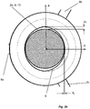
- the shape of the bearing surface 6 may be non-circular in the sense that a first distance d 1 , which is measured in a first direction in the plane and which forms a longest distance between the bearing surface 6 and a circle representing an outer envelope surface of the shaft 2 is larger than a second distance d 2 , which is measured in a second direction in the plane and which forms a shortest distance between the bearing surface 6 and the circle representing the outer envelope surface of the shaft 2, wherein the second distance d 2 is less than 70%, preferably less than 65% and more preferably less than 60% of the first distance d 1 .
- This non-circularity is provided in order to disturb the rolling effect and thereby to eliminate the vibration building up otherwise often occurring.
- the available choices of the values of the second distance d 2 may in such a case be described with the formula, 0 ⁇ d 2 ⁇ Y x d 1 , where Y is 0,7, preferably 0,65, and more preferably 0,6.
- the second distance d2 should be less than 56% of the distance d1 .
- the available choices of the values of the second distance d 2 may in such a case be described with the formula, 0 ⁇ d 2 ⁇ 0,56 x d 1 .
- the first distance d 1 may be said to be the longest distance between the bearing surface 6 and the circle representing the outer envelope surface of the shaft 2 and the second distance d 2 may be said to be the shortest distance between the bearing surface 6 and the circle representing the outer envelope surface of the shaft 2 in the same plane.
- the non-circular shape of the bearing surface 6 may at least be partly provided by the support ring 5 being tilted relative to the plane P having a normal parallel to the shaft axis L.
- the bearing surface 6 may be formed as an ellipse as seen in a projection in the plane having a normal parallel to the shaft axis L.
- the difference between the first distance d 1 and the second distance d 2 is dependent on how much the support ring 5 becomes tilted. A larger tilt gives a larger difference between the first and the second distance, d 1 and d 2 .
- the bigger the first distance d 1 is the bigger angle the support ring can be tilted.
- the support ring 5 may represent a bearing surface 6 having a circular shape in the plane having a normal parallel to the shaft axis L if not being tilted. Alternatively expressed, the support ring 5 may represent a bearing surface 6 having a circular shape in the plane having a normal parallel to the central axis C.
- the shaft support 1 may comprise a support structure 8a-c configured to extend downwardly.
- the support structure 8a-c may be attached to a bottom of a tank into which the rotatable shaft 2 is intended to extend into.
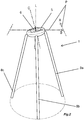
- the support structure 8a-c may comprise rods 8a-c as can be seen in e.g. figure 1 . Since support ring 5, in figure 1 , has a circular shape and is tilted, the lengths of the rods 8a-c have been adjusted into different lengths to connect to the bottom of the tank.
- the rods 8a-c are typically designed such that each rod carries the same forces while the agitator shaft 2 is rotating. They are evenly distributed on the support ring 5 and their connection points on the bottom of the tank is evenly distributed, preferably evenly distributed on a common geometrical circle, as may be seen in figure 2 .
- the support structure 8a-c may be configured to be attached centred relative to a geometrical point where the shaft axis L intersects the bottom of the tank. In the disclosed embodiment this is provided by the common geometrical circle of the connection points of the rods 8a-c having a centre point coinciding with the geometrical point where the shaft axis L intersects the bottom of the tank
- the bearing surface 6 of the shaft support 1 may extend circularly around the central geometrical axis C of the support ring 5.
- the distance from the central geometrical axis C of the support ring 5 to the bearing surface 6 may be equal in each point in a plane, having normal parallel to the central geometrical axis C, around the circular extension of the bearing surface 6.
- the radial thickness of the support ring 5 is preferably uniform as seen along the circular shape around the central geometrical axis C, as e.g. may be seen in figure 2 .
- the extension along the central geometrical axis C is preferably uniform as seen along the circular shape around the central geometrical axis C, as e.g. may be seen in figure 2 .
- the bearing surface 6 may have a convex cross-sectional shape, as seen in a radial plane extending radially from the central geometrical axis C of the support ring 5.
- the shape is convex in the sense that a central portion of the bearing surface 6, as seen along the central geometrical axis C, of the bearing surface 6 bulges inwardly towards the central geometrical axis C.
- the convex shape is preferably uniform as seen along the bearing surface 6 extending around the central geometrical axis C.
- the support ring 5 is shaped from a rod having a circular cross-section being bent into a circle. Thereby a convex bearing surface 6 is achieved in a robust and straight-forward manner.
- the bearing surface 6 may be machined to the convex cross-sectional shape.
- the bearing surface 6 may e.g. be based on a circular rod and be machined to provide a smoother surface than the surface formed by the circular rod as such.
- Such machined bearing surface 6 may e.g. have a radius of curvature being greater than the radius of the circular cross-section of the rod.
- the support ring may also be machined from a solid block such as a circular disk.
- the support ring 5 may be made of a hard material which has durable properties. This material may for instance be a metal, as well as another material with similar durable properties. It may be noted that the support ring 5 may be manufactured from one material and the bearing surface 6 may be manufactured from another material. In such a case, the bearing surface 6 may e.g. be formed of an inlay, such as an internal bushing. In such a case, the material of the bearing surface 6 is typically harder and more wear-resistant than the material from which the body of the support ring 5 is formed.
- the bearing surface 6 may be configured to allow the lower portion of the rotatable shaft 2 to slidable move up and down relatively to the bearing surface 6.
- the rotatable shaft 2 is slidable movable up and down in a longitudinal direction of the shaft axis L relative the bearing surface 6. It may in this context be noted that during normal operation, the agitator shaft 2 as such does typically not move up and down. However, the fact that the lower portion of the rotatable shaft 2 is slidable movable relative to the bearing surface 6 facilitates installation. Moreover, it makes it easy to provide the non-circularity by tilting the support ring 5 with its bearing surface 6.
- the lower portion of the agitator shaft 2 may be provided with a bushing 10.
- the bushing 10 is configured to interact with the bearing surface 6 of the shaft support 1.
- the bushing 10 may be composed of a food grade material, since the applications of an agitator 3 often is used in food industry as well as industries where there is a high demand on good hygiene.
- a food grade material must be able to be easily and efficiently cleaned.
- the material is typically not allowed to emit toxins or small pieces of material. It is also an advantage if the material is able to slide with a low friction.
- Materials which fulfill these requirements are for examples a polymer-based or a ceramic-based materials.
- the bushing 10 may be made of a material being softer than the material forming the bearing surface 6.
- friction will be accomplished. Thereby there is provided a greater tendency towards that the bushing 10 is to be replaced more often than the support ring 5. Since the bushing 10 at the lower portion of the agitator shaft 2 is comparably easy to replace, it is beneficial for the maintenance of the agitator 3 to have a bushing 10 being formed of a material being softer than the material chosen for the bearing surface 6.
- the agitator 3 may be designed such that there is a a radial play between the bearing surface 6 and the lower portion of the agitator shaft 2 as may be seen e.g. in figures 3a and 3b . If a bushing 10 is present, the agitator 3 may be designed such that there is a radial play between the bearing surface 6 and the bushing 10 at the lower portion of the agitator shaft 2. It may be noted that when the agitator shaft 2 rotates, it will typically abut somewhere on the bearing surface 6 inside the support ring 5, such that there is not a radial play around the complete circumference. However, the radial play will typically move around the inside of the support ring 5. Moreover, if the tank is emptied and cleaned, any cleaning fluid will act on the agitator shaft 2 and will typically move the agitator shaft 2 such that the cleaning fluid during the cleaning cycle will get access to all points of the bearing surface 6.
- the bearing surface 6 may define a smallest geometrical cylinder of free space along the shaft axis L.
- the smallest geometrical cylinder of free space may have a diameter being larger than the diameter of the lower portion of the agitator shaft 2. If a bushing 10 is present, the smallest geometrical cylinder of free space may have a diameter being larger than the diameter of the bushing of the lower portion of the agitator shaft 2.
- the smallest geometrical cylinder of free space has a diameter being at least 1% larger, more preferably 5% larger, than the diameter of the lower portion of the agitator shaft 2 or the bushing 10.
- the shaft support 1 may for instance have a differently designed support structure. It may e.g. have a different number of rods. It may e.g. have a ring structure interconnecting the lower ends of the rods. It may e.g. be designed as a box-structure, e.g. partly open or completely closed.
- the number of agitator blades 7 may also differ due to the application and typically dependent on the solution that should be agitating.
- the number of agitator blades may be 2, 3, 4, 5, 6 or more.
- the agitator blades 7 may further be of various shapes, sizes and material.
- the ring 17 which the agitator blades 7 are connected to could either be fixed or movable.
- the agitator blades 7 may be connected directly to the agitator shaft 2.
- the diameter of the agitator shaft 2 and/or the distribution of the agitator blades 7 may vary along the agitator shaft 2.
Landscapes
- Engineering & Computer Science (AREA)
- General Engineering & Computer Science (AREA)
- Physics & Mathematics (AREA)
- Fluid Mechanics (AREA)
- Mechanical Engineering (AREA)
- Chemical & Material Sciences (AREA)
- Chemical Kinetics & Catalysis (AREA)
- Accessories For Mixers (AREA)
- Mixers Of The Rotary Stirring Type (AREA)
Abstract
Description
- The invention relates to a shaft support for supporting a lower portion of a rotatable shaft extending downwardly along a shaft axis from a drive arrangement. The invention also relates to an agitator configured to be installed in a tank.
- Chemical and food processing operations often employ mixing tanks including a vertical agitator shaft which extends down into a tank and which carries agitator blades for agitating or mixing the product or products in the tank. The agitator shaft is typically supported or guided by a shaft support, supporting a lower end of a rotatable shaft.
- One problem often encountered is that vibrations occurs. This is often due to forces caused by radial displacement of the agitator shaft. Radial displacement is more common for long and slender agitator shafts than it is for thicker shafts. Vibrations are typically undesirable since they typically increase wear of the components and since they may have a negative impact on the function of the agitator. To address this issue of undesired vibrations, there has been presented numerous attempts to provide elaborated shaft supports.
- However, the provision of an elaborate shaft support typically has a negative impact on cleanability.
-
- In
US 6386753 there is disclosed a shaft support in a mixing vessel having a support ring with strut pairs with an inclination angle between the struts in each pair to maintaining radial support of the shaft and to resist torsional forces. The strut pair assemblies extend radially outwardly from the shaft and are attached to the vessel wall to support the bearing holder. Such a configuration is complicated to manufacture and to install. -
US 7387431 approaches the problems associated with the cleaning of a shaft support. There is disclosed a sanitary shaft support having a bearing assembly supported by legs welded to the bottom of the vessel. It is said that this shaft has the advantages of easy cleanability and easy replacement of wear parts without disturbing the rest of the agitator. However, design of the support shaft is complicated since it comprises a plurality of bushings and other ring-shaped elements interconnected to each other and it sets high demands on alignment when installing the shaft support relative to the shaft. - In
US 5618107 there is disclosed a bearing assembly in a bottom mounted shaft support for an agitator. The bearing assembly is provided with a locking mechanism having J-shaped grooves and pins interacting with the grooves. Such a design makes it difficult to clean the shaft support. In order to somewhat address the cleaning issue, the bearing assembly includes a plurality of circumferentially spaced axially extended grooves in the inner and outer peripheries, which are said to facilitate cleaning of the bearing assembly in place. - Thus, there is still room for improvements when it comes to providing a shaft support which is able to eliminate vibrations in a robust and cost-efficient manner, which is easy to install, and which is able to be easily and efficiently cleaned.
- In view of that stated above, the object of the present invention is to provide a design that adequately addresses the design criteria concerning easy installation, eliminate vibrations and being easy and efficient to clean.
- According to a first aspect this object has been achieved by a shaft support supporting a lower portion of a rotatable shaft extending downwardly along a shaft axis from a drive arrangement. The shaft support comprises:
- a support ring extending around a central geometrical axis and being configured to circumscribe the lower portion of the rotatable shaft, the support ring having an inwardly facing bearing surface configured to form a slide bearing journaling the lower portion of the rotatable shaft,
- wherein the bearing surface has a non-circular shape, as seen in a projection in a plane having a normal parallel to the shaft axis, in the sense that a first distance, which is measured in a first direction in the plane and which forms a longest distance between the bearing surface and a circle representing an outer envelope surface of the shaft is larger than a second distance, which is measured in a second direction in the plane and which forms a shortest distance between the bearing surface and the circle representing the outer envelope surface of the shaft, wherein the second distance is less than 70%, preferably less than 65% and more preferably less than 60% of the first distance of the first distance.
- The available choices of the values of the second distance d2 may in such a case be described with the formula, 0 < d2 < Y x d1, where Y is 0,7, preferably 0,65, and more preferably 0,6, where d1 is the first distance.
- Most preferably it has been found that the second distance d2 should be less than 56% of the distance d1. The available choices of the values of the second distance d2 may in such a case be described with the formula,

- According to a second aspect the above object has also been achieved by an agitator configured to be installed in a tank, the agitator comprising:
- a drive arrangement,
- an agitator shaft being provided with agitator blades and being configured to extend downwardly from the drive arrangement along a shaft axis and to be rotated about the shaft axis by the drive arrangement, and
- a shaft support, wherein the shaft support is of the kind introduced above and disclosed in more details below.
- As mentioned above, the shaft support is configured to support a lower portion of a rotatable shaft extending downwardly along a shaft axis from a drive arrangement. The drive arrangement is configured to rotate the agitator shaft about the shaft axis. Thus, the support structure and the lower portion of the rotatable shaft are configured to interact when the agitator shaft is rotating. The agitator shaft will rotate inside the support ring of the shaft support and will be journaled by the bearing surface having a non-circular shape.
- By designing the shaft support and the agitator with a bearing surface with the non-circularity as introduced above, and as disclosed in more detail below, there is provided a shaft support which counter-acts build-up of vibrations in the agitator in a robust manner. This non-circularity disturbs a rolling effect which otherwise may occur. The rolling effect occurs when the lower portion of the agitator shaft starts to roll on the curvature of the support ring instead of sliding. However, since the rolling effect in a sense makes the shaft and bearing surface to temporarily act as an internal gear, the difference in the rotation of the shaft and the rolling results in that the rolling effect is repeatedly lost, which in turn results in vibrations. Thus, the non-circularity disturbs the rolling effect which otherwise may occur and thereby counter-acts the occurrence of vibration building up otherwise often occurring. By counter-acting the vibration build-up it becomes possible to use comparably slender agitator shafts, which in turn is cost-effective and which also reduces the weight of the agitator shaft.
- Moreover, the design also provides the advantage of counter-acting vibration build up, by a shaft support which may be formed of a comparable small number of components and components that may be manufactured in a cost-efficient manner. Moreover, the robustness of the design makes it easy to install the shaft support together with the agitator.
- The lower portion of the agitator shaft may be provided with a bushing configured to interact with the bearing surface of the shaft support.
- The provision of a bushing on the lower portion of the agitator shaft may be used as an indicator where the interaction with support ring of the shaft support is intended to be formed. This may be used as a guide or a control-feature facilitating an easy and correct installation. The bushing may be configured to provide a reduced friction when sliding on the bearing surface. Moreover, the provision of a bushing may also be used to provide a suitable combination of materials of the bearing surface and the bushing. A suitable combination of materials may e.g. be selected such that is the bushing which is worn, and the bearing surface is not worn, or at least only worn to a small extent, whereby maintenance is facilitated.
- It may in this context be noted that the feature - a circle representing an outer envelope surface of the shaft - is introduced to take into account that the actual envelope surface of the lower portion of the shaft formed of the shaft as such or of the bushing may have a shape deviating from a circular shape to such an extent that it has an impact on the determination of the first and second distances. The circle representing an outer envelope surface of the shaft is in such a case typically a circle with a diameter being equal to the nominal outer diameter of the shaft or bushing.
- The non-circular shape of the bearing surface, as seen in the plane having a normal parallel to the shaft axis, may be provided by manufacturing, such as machining, the bearing surface such that it obtains a non-circular shape, such as an ellipsoid or oval shape.
- The non-circular shape of the bearing surface, as seen in the plane having a normal parallel to the shaft axis, may at least partly be provided by the support ring being tilted relative to the plane having a normal parallel to the shaft axis. By this, the bearing surface may be circular in one plane and provides an ellipse shaped bearing surface when tilted and projected down into another plane. The other plane is the plane having a normal parallel to the shaft axis when the shaft support is interacting with the agitator. It is also advantageous in that in this case, the contact point between lower portion of the shaft and the bearing surface will move around the lower portion of the shaft and will simultaneously move up and down on the lower portion due to the tilt angle of the bearing surface. This reduces the wear of the lower portion of the shaft, since the wear will over time be distributed over a cylindrical surface compared to a line contact. In the preferred embodiment, the bearing surface is circular around a central axis and the non-circularity is provided fully by the support ring being tilted relative to the plane having a normal parallel to the shaft axis.
- The bearing surface may be formed as an ellipse as seen in a projection in the plane having a normal parallel to the shaft axis.
- By this, the bearing surface may be circular in one plane and provides an ellipse shaped bearing surface when tilted and projected down into another plane. The other plane is the plane having a normal parallel to the shaft axis when the shaft support is interacting with the agitator.
- The ellipse shaped bearing, especially if provided by a circular bearing surface being tilted, provides counter-action of the vibrations without use of any additional components or advanced manufacture of the shaft support.
- The bearing surface of the shaft support may extend circularly around the central geometrical axis of the support ring. This facilitates manufacture of the bearing surface of the support ring.
- The bearing surface may have a convex cross-sectional shape, as seen in a radial plane extending radially from the central geometrical axis of the support ring, the bearing surface having a convex shape in the sense that a central portion of the bearing surface, as seen along the central geometrical axis, of the bearing surface bulges inwardly towards the central geometrical axis.
- The convex cross-sectional shape of the bearing surface provides a smooth surface without any sharp edges. The provision of a convex bearing surface is especially useful if the non-circularity is provided by tilting a circular bearing surface.
- The support ring is preferably made of metal. A support ring made of metal typically provides cost-efficient choose of material by providing a support ring which is easy to manufacture, and which typically is long-lived.
- The bearing surface may be configured to allow the lower portion of the rotatable shaft to slidably move up and down relative to the bearing surface. One advantage is that it facilitates installation.
- Moreover, it is also useful if the lower portion of the rotatable shaft is cylindrical and the bearing surface is tilted. In this case, the contact point between lower portion of the shaft and the bearing surface will move around the lower portion of the shaft and will simultaneously move up and down on the lower portion due to the tilt angle of the bearing surface. This reduces the wear of the lower portion of the shaft, since the wear will over time be distributed over a cylindrical surface compared to a line contact.
- The shaft support may comprise a support structure configured to extend downwardly and to be attached to a bottom of a tank into which the rotatable shaft is intended to extend into. By having the support structure attached to the bottom of the tank provides stability which addresses the design criteria of eliminating vibrations. It also makes it possible to provide an agitator able to blend the mixture in the entire tank since the agitator shaft with agitator blades may extend from the top of the tank down to the shaft support attached to the bottom of the tank.
- The support structure may be configured to be attached centred relative to a geometrical point where the shaft axis intersects the bottom of the tank. This facilitates installation.
- As mentioned above, the lower portion of the agitator shaft may be provided with a bushing configured to interact with the bearing surface of the shaft support.
- The bushing may be composed of polymer-based or ceramic-based material, preferable a food grade material.
- The bushing may be made of a material being softer than the material forming the bearing surface.
- By having a bushing made of a material being softer than the material of the bearing surface it is possible to make the bushing being worn out before the bearing surface.
- The agitator is preferably designed such that there is a radial play between the bearing surface and the lower portion of the agitator shaft. If there is a bushing present this would be that the agitator is preferably designed such that there is a radial play between the bearing surface and the bushing at the lower portion of the agitator shaft.
- The radial play between the bearing surface and the shaft or bushing provides spaces for easy and efficient cleaning. The radial play may be sufficiently large to make possible to see if the bearing or bushing are worn out or about to become worn out.
- The bearing surface may define a smallest geometrical cylinder of free space along the shaft axis, the smallest geometrical cylinder of free space may have a diameter being larger, preferably at least 1% larger, more preferably at least 5% larger, than the diameter of the lower portion of the agitator shaft, or the smallest geometrical cylinder of free space may have a diameter being larger than the diameter of the bushing at the lower portion of the agitator shaft if such a bushing is present. It may be noted that the diameter of the smallest geometrical cylinder of free space is the smallest distance appearing as measured between two opposing points of the bearing surface.
- The invention may also in short be said to relate to a shaft support for supporting a lower portion of a rotatable shaft of an agitator configured to be installed in a tank, the shaft support comprising a support ring with an inwardly facing bearing surface configured to form a slide bearing journaling a lower portion of the rotatable shaft, wherein the bearing surface has a non-circular shape in a plane having a normal parallel to the shaft axis.
- The invention will by way of example be described in more detail with reference to the appended schematic drawings, which shows a presently preferred embodiment of the invention.
-
Figure 1 discloses an agitator comprising a shaft provided with agitator blades, a drive arrangement and a shaft support. -
Figure 2 is a perspective view of the shaft support offigure 1 . -
Figure 3a is a top-plan view of the shaft support offigures 1 and2 . -
Figure 3b is an enlargement of part offigure 3a . -
Figure 4 is side view of the shaft support offigures 1-3 . -
Figure 5 is a cross-sectional view of a support ring of the shaft support. - In
figure 1 there is disclosed anagitator 3 configured to be installed in a tank. Theagitator 3 comprises adrive arrangement 4 and anagitator shaft 2. Theagitator shaft 2 extends downwardly from thedrive arrangement 4 along a shaft axis L down to ashaft support 1. The shaft axis L may also be referred to as a longitudinal direction L. - The
drive arrangement 4 may e.g. be a motor, such as an electrical motor, a hydraulic motor or the like. Depending upon the working range of the motor when it comes to rotational speed and torque and the intended rotational speed and torque demand of theagitator shaft 2, thedrive arrangement 3 may include a gear. Thedrive arrangement 3 may also comprise a clutch. The clutch may be used during start-up and shut-down. A clutch may also be used to release the connection between the motor and theagitator shaft 2 as a safety precaution, such as if theagitator shaft 2 becomes stuck. - The
agitator shaft 2 is provided with a plurality ofagitator blades 7. Theagitator blades 7 are distributed along the shaft axis L and are provided along at least a portion of theshaft 2, from thedrive arrangement 4 down towards theshaft support 1. Theagitator blades 7 each extend outwardly from theagitator shaft 2. In the disclosed embodiment they extend perpendicular to the shaft axis L. In the disclosed embodiment there are fouragitator blades 7 at each longitudinal position where there are provided blades. The blades are attached to aring 17 which in turn encloses and is connected to a small portion of theagitator shaft 2. Theagitator blades 7 are attached to theshaft 2 such that theblades 7 sweep around the shaft axis L when theshaft 2 is rotated by thedrive arrangement 4. The actual design and configuration may be varied in a number of different ways. - As disclosed in
figure 1 , a lower portion of therotatable shaft 2 is supported by theshaft support 1. Theshaft support 1 comprises asupport ring 5. Thesupport ring 5 extends around a central geometrical axis C. Thesupport ring 5 is configured to circumscribe the lower portion of therotatable shaft 2. Theagitator shaft 2 is configured to be inserted from the top of thesupport ring 5. Thesupport ring 5 has preferably an extension along the shaft axis L and a position as seen along the shaft axis L such that theshaft 2 extends completely through thesupport ring 5. Thesupport ring 5 is configured to be connected to a bottom or a wall, preferably the bottom, of the tank and be held in the intended position by asupport structure 8a-c. Thesupport structure 8a-c extends downwardly along the shaft axis L from thesupport ring 5. - The
support ring 5 has an inwardly facing bearingsurface 6 which is configured to form a slide bearing journaling the lower portion of therotatable shaft 2. Thus, the bearingsurface 6 of theshaft support 1 support a lower portion of theagitator shaft 2. - As shown in
figures 3a-b , the shape of the bearingsurface 6 is non-circular as seen in the projection in a plane, the plane of the paper infigures 3a and3b , having a normal parallel to the shaft axis L. The shape of the bearingsurface 6 may be non-circular in the sense that a first distance d1, which is measured in a first direction in the plane and which forms a longest distance between thebearing surface 6 and a circle representing an outer envelope surface of theshaft 2 is larger than a second distance d2, which is measured in a second direction in the plane and which forms a shortest distance between thebearing surface 6 and the circle representing the outer envelope surface of theshaft 2, wherein the second distance d2 is less than 70%, preferably less than 65% and more preferably less than 60% of the first distance d1. This non-circularity is provided in order to disturb the rolling effect and thereby to eliminate the vibration building up otherwise often occurring. - The available choices of the values of the second distance d2 may in such a case be described with the formula, 0 < d2 < Y x d1, where Y is 0,7, preferably 0,65, and more preferably 0,6.
- Most preferably it has been found that the second distance d2 should be less than 56% of the distance d1 . The available choices of the values of the second distance d2 may in such a case be described with the formula, 0 < d2 < 0,56 x d1.
- The first distance d1 may be said to be the longest distance between the
bearing surface 6 and the circle representing the outer envelope surface of theshaft 2 and the second distance d2 may be said to be the shortest distance between thebearing surface 6 and the circle representing the outer envelope surface of theshaft 2 in the same plane. - The non-circular shape of the bearing
surface 6 may at least be partly provided by thesupport ring 5 being tilted relative to the plane P having a normal parallel to the shaft axis L. The bearingsurface 6 may be formed as an ellipse as seen in a projection in the plane having a normal parallel to the shaft axis L. The difference between the first distance d1 and the second distance d2 is dependent on how much thesupport ring 5 becomes tilted. A larger tilt gives a larger difference between the first and the second distance, d1 and d2. The bigger the first distance d1 is the bigger angle the support ring can be tilted. Thesupport ring 5 may represent abearing surface 6 having a circular shape in the plane having a normal parallel to the shaft axis L if not being tilted. Alternatively expressed, thesupport ring 5 may represent abearing surface 6 having a circular shape in the plane having a normal parallel to the central axis C. - The
shaft support 1 may comprise asupport structure 8a-c configured to extend downwardly. Thesupport structure 8a-c may be attached to a bottom of a tank into which therotatable shaft 2 is intended to extend into. Thesupport structure 8a-c may compriserods 8a-c as can be seen in e.g.figure 1 . Sincesupport ring 5, infigure 1 , has a circular shape and is tilted, the lengths of therods 8a-c have been adjusted into different lengths to connect to the bottom of the tank. Therods 8a-c are typically designed such that each rod carries the same forces while theagitator shaft 2 is rotating. They are evenly distributed on thesupport ring 5 and their connection points on the bottom of the tank is evenly distributed, preferably evenly distributed on a common geometrical circle, as may be seen infigure 2 . - The
support structure 8a-c may be configured to be attached centred relative to a geometrical point where the shaft axis L intersects the bottom of the tank. In the disclosed embodiment this is provided by the common geometrical circle of the connection points of therods 8a-c having a centre point coinciding with the geometrical point where the shaft axis L intersects the bottom of the tank - The bearing
surface 6 of theshaft support 1 may extend circularly around the central geometrical axis C of thesupport ring 5. The distance from the central geometrical axis C of thesupport ring 5 to thebearing surface 6 may be equal in each point in a plane, having normal parallel to the central geometrical axis C, around the circular extension of the bearingsurface 6. The radial thickness of thesupport ring 5 is preferably uniform as seen along the circular shape around the central geometrical axis C, as e.g. may be seen infigure 2 . The extension along the central geometrical axis C is preferably uniform as seen along the circular shape around the central geometrical axis C, as e.g. may be seen infigure 2 . - As e.g. shown in
figure 5 , the bearingsurface 6 may have a convex cross-sectional shape, as seen in a radial plane extending radially from the central geometrical axis C of thesupport ring 5. The shape is convex in the sense that a central portion of the bearingsurface 6, as seen along the central geometrical axis C, of the bearingsurface 6 bulges inwardly towards the central geometrical axis C. The convex shape is preferably uniform as seen along the bearingsurface 6 extending around the central geometrical axis C. In the disclosed embodiment, thesupport ring 5 is shaped from a rod having a circular cross-section being bent into a circle. Thereby aconvex bearing surface 6 is achieved in a robust and straight-forward manner. It may be noted that the bearingsurface 6 may be machined to the convex cross-sectional shape. The bearingsurface 6 may e.g. be based on a circular rod and be machined to provide a smoother surface than the surface formed by the circular rod as such. Suchmachined bearing surface 6 may e.g. have a radius of curvature being greater than the radius of the circular cross-section of the rod. The support ring may also be machined from a solid block such as a circular disk. - The
support ring 5 may be made of a hard material which has durable properties. This material may for instance be a metal, as well as another material with similar durable properties. It may be noted that thesupport ring 5 may be manufactured from one material and thebearing surface 6 may be manufactured from another material. In such a case, the bearingsurface 6 may e.g. be formed of an inlay, such as an internal bushing. In such a case, the material of the bearingsurface 6 is typically harder and more wear-resistant than the material from which the body of thesupport ring 5 is formed. - The bearing
surface 6 may be configured to allow the lower portion of therotatable shaft 2 to slidable move up and down relatively to thebearing surface 6. Therotatable shaft 2 is slidable movable up and down in a longitudinal direction of the shaft axis L relative thebearing surface 6. It may in this context be noted that during normal operation, theagitator shaft 2 as such does typically not move up and down. However, the fact that the lower portion of therotatable shaft 2 is slidable movable relative to thebearing surface 6 facilitates installation. Moreover, it makes it easy to provide the non-circularity by tilting thesupport ring 5 with itsbearing surface 6. This is so since a tiltedsupport ring 5 results in that the point of contact moves up and down on the lower portion of thesupport shaft 2, and by allowing the lower portion of therotatable shaft 2 to be slidable movable relative to thebearing surface 6, the movement of the contact point is easily accommodated. - The lower portion of the
agitator shaft 2 may be provided with abushing 10. Thebushing 10 is configured to interact with the bearingsurface 6 of theshaft support 1. Thebushing 10 may be composed of a food grade material, since the applications of anagitator 3 often is used in food industry as well as industries where there is a high demand on good hygiene. A food grade material must be able to be easily and efficiently cleaned. The material is typically not allowed to emit toxins or small pieces of material. It is also an advantage if the material is able to slide with a low friction. Materials which fulfill these requirements are for examples a polymer-based or a ceramic-based materials. - The
bushing 10 may be made of a material being softer than the material forming thebearing surface 6. When thebushing 10 is acting on the curvature of the bearingsurface 6 friction will be accomplished. Thereby there is provided a greater tendency towards that thebushing 10 is to be replaced more often than thesupport ring 5. Since thebushing 10 at the lower portion of theagitator shaft 2 is comparably easy to replace, it is beneficial for the maintenance of theagitator 3 to have abushing 10 being formed of a material being softer than the material chosen for thebearing surface 6. - The
agitator 3 may be designed such that there is a a radial play between thebearing surface 6 and the lower portion of theagitator shaft 2 as may be seen e.g. infigures 3a and3b . If abushing 10 is present, theagitator 3 may be designed such that there is a radial play between thebearing surface 6 and thebushing 10 at the lower portion of theagitator shaft 2. It may be noted that when theagitator shaft 2 rotates, it will typically abut somewhere on thebearing surface 6 inside thesupport ring 5, such that there is not a radial play around the complete circumference. However, the radial play will typically move around the inside of thesupport ring 5. Moreover, if the tank is emptied and cleaned, any cleaning fluid will act on theagitator shaft 2 and will typically move theagitator shaft 2 such that the cleaning fluid during the cleaning cycle will get access to all points of the bearingsurface 6. - The bearing
surface 6 may define a smallest geometrical cylinder of free space along the shaft axis L. The smallest geometrical cylinder of free space may have a diameter being larger than the diameter of the lower portion of theagitator shaft 2. If abushing 10 is present, the smallest geometrical cylinder of free space may have a diameter being larger than the diameter of the bushing of the lower portion of theagitator shaft 2. Preferably, the smallest geometrical cylinder of free space has a diameter being at least 1% larger, more preferably 5% larger, than the diameter of the lower portion of theagitator shaft 2 or thebushing 10. - It is contemplated that there are numerous modifications of the embodiments described herein, which are still within the scope of the invention as defined by the appended claims.
- The
shaft support 1 may for instance have a differently designed support structure. It may e.g. have a different number of rods. It may e.g. have a ring structure interconnecting the lower ends of the rods. It may e.g. be designed as a box-structure, e.g. partly open or completely closed. - The number of
agitator blades 7 may also differ due to the application and typically dependent on the solution that should be agitating. For example, the number of agitator blades may be 2, 3, 4, 5, 6 or more. Theagitator blades 7 may further be of various shapes, sizes and material. Thering 17 which theagitator blades 7 are connected to could either be fixed or movable. Theagitator blades 7 may be connected directly to theagitator shaft 2. - The diameter of the
agitator shaft 2 and/or the distribution of theagitator blades 7 may vary along theagitator shaft 2. - Additionally, variations to the disclosed embodiments can be understood and effected by the skilled person in practicing the claimed invention, from a study of the drawings, the disclosure, and the appended claims. In the claims, the word "comprising" does not exclude other elements or steps, and the indefinite article "a" or "an" does not exclude a plurality. The mere fact that certain measures are recited in mutually different dependent claims does not indicate that a combination of these measured cannot be used to advantage.
Claims (15)
- A shaft support (1) for supporting a lower portion of a rotatable shaft (2) extending downwardly along a shaft axis (L) from a drive arrangement (4), the shaft support (1) comprising:a support ring (5) extending around a central geometrical axis (C) and being configured to circumscribe the lower portion of the rotatable shaft (2), the support ring (5) having an inwardly facing bearing surface (6) configured to form a slide bearing journaling the lower portion of the rotatable shaft (2),wherein the bearing surface (6) has a non-circular shape, as seen in a projection in a plane (P) having a normal parallel to the shaft axis (L), in the sense that a first distance (d1), which is measured in a first direction (A) in the plane (P) and which forms a longest distance between the bearing surface (6) and a circle (9) representing an outer envelope surface (2a, 10) of the shaft (2) is larger than a second distance (d2), which is measured in a second direction (B) in the plane (P) and which forms a shortest distance between the bearing surface (6) and the circle (9) representing the outer envelope surface (2a, 10) of the shaft (2), wherein the second distance (d2) is less than 70% of the first distance (di).
- The shaft support ring (5) according to claim 1, wherein the non-circular shape of the bearing surface (6), as seen in the plane (P) having a normal parallel to the shaft axis (L), is at least partly provided by the support ring (5) being tilted relative to the plane (P) having a normal parallel to the shaft axis (L).
- The shaft support (1) according to claim 1 or 2, wherein the bearing surface (6) is formed as an ellipse as seen in a projection in the plane (P) having a normal parallel to the shaft axis (L).
- The shaft support (1) according to any one of claims 1-3, wherein the bearing surface (6) extends circularly around the central geometrical axis (C) of the support ring (5).
- The shaft support (1) according to any one of claims 1-4, wherein the bearing surface (6) has a convex cross-sectional shape, as seen in a radial plane extending radially from the central geometrical axis (C) of the support ring (5), the bearing surface (6) having a convex shape in the sense that a central portion of the bearing surface (6), as seen along the central geometrical axis (C), of the bearing surface (6) bulges inwardly towards the central geometrical axis (C).
- The shaft support (1) according to any one of claims 1-5, wherein the support ring (5) is made of metal.
- The shaft support (1) according to any one of claims 1-6, wherein the bearing surface (6) is configured to allow the lower portion of the rotatable shaft (2) to slidably move up and down relative to the bearing surface (6).
- The shaft support (1) according to any one of claims 1-7, the shaft support (1) comprising a support structure (8) configured to extend downwardly and to be attached to a bottom of a tank into which the rotatable shaft (2) is intended to extend into.
- The shaft support (1) according to claim 6, wherein the support structure (8) is configured to be attached centred relative to a geometrical point where the shaft axis (L) intersects the bottom of the tank.
- An agitator (3) configured to be installed in a tank, the agitator comprising
a drive arrangement (4),
an agitator shaft (3) being provided with agitator blades (7) and being configured to extend downwardly from the drive arrangement (4) along a shaft axis (L) and to be rotated about the shaft axis (L) by the drive arrangement (4), and
a shaft support (1) according to any one of claims 1-9. - The agitator (3) according to claim 10, wherein the lower portion of the agitator shaft (2) is provided with a bushing (10) configured to interact with the bearing surface (6) of the shaft support (1).
- The agitator (3) according to claim 11, wherein the bushing (10) is composed of polymer-based or ceramic-based material, preferably a food grade material.
- The agitator (3) according to claim 11 or 12, wherein the bushing (10) is made of a material being softer than the material forming the bearing surface (6).
- The agitator (3) according to any one of claims 10-13, wherein there is a radial play between the bearing surface (6) and the lower portion of the agitator shaft (2), or a radial play between the bearing surface (6) and the bushing (10) at the lower portion of the agitator shaft (2) if such bushing (10) is present.
- The agitator according to claim 14, wherein the bearing surface (6) defines a smallest geometrical cylinder of free space along the shaft axis (L), the smallest geometrical cylinder of free space having a diameter being larger, preferably at least 1% larger, preferably at least 5% larger, than the diameter of the lower portion of the agitator shaft (L), or the smallest geometrical cylinder of free space having a diameter being larger than the diameter of the bushing (10) at the lower portion of the agitator shaft (2) if such a bushing is present.
Priority Applications (7)
| Application Number | Priority Date | Filing Date | Title |
|---|---|---|---|
| DK19215234.6T DK3834922T3 (en) | 2019-12-11 | 2019-12-11 | SHAFT BRACKET TO SUPPORT AN AGITATOR SHAFT AND AN AGITATOR |
| EP19215234.6A EP3834922B1 (en) | 2019-12-11 | 2019-12-11 | Shaft support for supporting an agitator shaft and an agitator |
| PL19215234.6T PL3834922T3 (en) | 2019-12-11 | 2019-12-11 | Shaft support for supporting an agitator shaft and an agitator |
| PCT/EP2020/085246 WO2021116162A1 (en) | 2019-12-11 | 2020-12-09 | Shaft support for supporting an agitator shaft and an agitator |
| US17/783,412 US12569818B2 (en) | 2019-12-11 | 2020-12-09 | Shaft support for supporting an agitator shaft and an agitator |
| KR1020227023153A KR102709579B1 (en) | 2019-12-11 | 2020-12-09 | Shaft support and stirrer for supporting the stirrer shaft |
| CN202080085738.6A CN114786801A (en) | 2019-12-11 | 2020-12-09 | Shaft bearing for bearing a stirrer shaft and stirrer |
Applications Claiming Priority (1)
| Application Number | Priority Date | Filing Date | Title |
|---|---|---|---|
| EP19215234.6A EP3834922B1 (en) | 2019-12-11 | 2019-12-11 | Shaft support for supporting an agitator shaft and an agitator |
Publications (2)
| Publication Number | Publication Date |
|---|---|
| EP3834922A1 true EP3834922A1 (en) | 2021-06-16 |
| EP3834922B1 EP3834922B1 (en) | 2022-06-15 |
Family
ID=68886828
Family Applications (1)
| Application Number | Title | Priority Date | Filing Date |
|---|---|---|---|
| EP19215234.6A Active EP3834922B1 (en) | 2019-12-11 | 2019-12-11 | Shaft support for supporting an agitator shaft and an agitator |
Country Status (7)
| Country | Link |
|---|---|
| US (1) | US12569818B2 (en) |
| EP (1) | EP3834922B1 (en) |
| KR (1) | KR102709579B1 (en) |
| CN (1) | CN114786801A (en) |
| DK (1) | DK3834922T3 (en) |
| PL (1) | PL3834922T3 (en) |
| WO (1) | WO2021116162A1 (en) |
Citations (9)
| Publication number | Priority date | Publication date | Assignee | Title |
|---|---|---|---|---|
| US4668107A (en) * | 1985-08-14 | 1987-05-26 | Automotive Engine Associates | Engine bearings |
| US5618107A (en) | 1996-06-07 | 1997-04-08 | A&B Process Systems Corporation | Bearing assembly for agitator shaft |
| US6386753B1 (en) | 2000-12-29 | 2002-05-14 | Spx Corporation | Support assembly and method for supporting a steady bearing |
| US7387431B2 (en) | 2005-03-28 | 2008-06-17 | Spx Corporation | Sanitary steady bearing and method |
| US20130149140A1 (en) * | 2011-12-07 | 2013-06-13 | Asia Vital Components Co., Ltd. | Bearing structure and cooling fan using same |
| EP2693017A1 (en) * | 2011-03-29 | 2014-02-05 | Mitsubishi Heavy Industries, Ltd. | Turbocharger and method for manufacturing floating bush |
| EP2998596A1 (en) * | 2013-07-31 | 2016-03-23 | Nakamura Industrial MFG. Co., Ltd | Low vibration floating metal bearing |
| EP3130812A1 (en) * | 2015-08-14 | 2017-02-15 | Siemens Aktiengesellschaft | Multi-segment sliding bearing and method for profiling the multi-segment sliding bearing |
| WO2017203880A1 (en) * | 2016-05-27 | 2017-11-30 | 株式会社Ihi | Bearing and supercharger |
Family Cites Families (13)
| Publication number | Priority date | Publication date | Assignee | Title |
|---|---|---|---|---|
| JPS5765412A (en) | 1980-10-06 | 1982-04-21 | Ebara Corp | Vibration-suppressing pad bearing |
| JPH0610945A (en) | 1992-04-27 | 1994-01-21 | Hitachi Koki Co Ltd | Dynamic pressure bearing and rotary polygon mirror device using the same |
| JPH11336744A (en) * | 1998-05-28 | 1999-12-07 | Ishikawajima Harima Heavy Ind Co Ltd | Corrugated bearing |
| JP2000161346A (en) | 1998-11-27 | 2000-06-13 | Nsk Ltd | Spindle motor |
| JP4169898B2 (en) | 2000-02-21 | 2008-10-22 | 株式会社荏原製作所 | Vertical drainage pump |
| US6868810B2 (en) | 2002-02-06 | 2005-03-22 | Honda Giken Kogyo Kabushiki Kaisha | Bearing device |
| JP4046733B2 (en) | 2004-03-15 | 2008-02-13 | 大同メタル工業株式会社 | Foil type hydrodynamic journal bearing and manufacturing method thereof. |
| KR200387525Y1 (en) | 2005-04-06 | 2005-06-17 | 주식회사 엣센텍 | Axle swings prevented agitator |
| JP3173801U (en) | 2011-12-09 | 2012-02-23 | 奇▲こう▼科技股▲ふん▼有限公司 | Bearing structure and heat dissipation fan including the same |
| CN105771847A (en) | 2014-12-25 | 2016-07-20 | 天津市豪饰地毯有限公司 | Temperature control stirring chemical reactor |
| EP3241608B1 (en) | 2016-05-02 | 2020-04-08 | Levitronix GmbH | Mixing device and disposable device for such a mixing device |
| US10557498B1 (en) | 2018-10-12 | 2020-02-11 | Borgwarner Inc. | Full-floating bearing and turbocharger including the same |
| CN109869411B (en) | 2019-04-09 | 2024-03-26 | 哈尔滨广瀚动力传动有限公司 | High-speed rotor system with elliptical bearing and four-oil-blade bearing coaxially and four-support |
-
2019
- 2019-12-11 PL PL19215234.6T patent/PL3834922T3/en unknown
- 2019-12-11 EP EP19215234.6A patent/EP3834922B1/en active Active
- 2019-12-11 DK DK19215234.6T patent/DK3834922T3/en active
-
2020
- 2020-12-09 US US17/783,412 patent/US12569818B2/en active Active
- 2020-12-09 KR KR1020227023153A patent/KR102709579B1/en active Active
- 2020-12-09 WO PCT/EP2020/085246 patent/WO2021116162A1/en not_active Ceased
- 2020-12-09 CN CN202080085738.6A patent/CN114786801A/en active Pending
Patent Citations (9)
| Publication number | Priority date | Publication date | Assignee | Title |
|---|---|---|---|---|
| US4668107A (en) * | 1985-08-14 | 1987-05-26 | Automotive Engine Associates | Engine bearings |
| US5618107A (en) | 1996-06-07 | 1997-04-08 | A&B Process Systems Corporation | Bearing assembly for agitator shaft |
| US6386753B1 (en) | 2000-12-29 | 2002-05-14 | Spx Corporation | Support assembly and method for supporting a steady bearing |
| US7387431B2 (en) | 2005-03-28 | 2008-06-17 | Spx Corporation | Sanitary steady bearing and method |
| EP2693017A1 (en) * | 2011-03-29 | 2014-02-05 | Mitsubishi Heavy Industries, Ltd. | Turbocharger and method for manufacturing floating bush |
| US20130149140A1 (en) * | 2011-12-07 | 2013-06-13 | Asia Vital Components Co., Ltd. | Bearing structure and cooling fan using same |
| EP2998596A1 (en) * | 2013-07-31 | 2016-03-23 | Nakamura Industrial MFG. Co., Ltd | Low vibration floating metal bearing |
| EP3130812A1 (en) * | 2015-08-14 | 2017-02-15 | Siemens Aktiengesellschaft | Multi-segment sliding bearing and method for profiling the multi-segment sliding bearing |
| WO2017203880A1 (en) * | 2016-05-27 | 2017-11-30 | 株式会社Ihi | Bearing and supercharger |
Also Published As
| Publication number | Publication date |
|---|---|
| US12569818B2 (en) | 2026-03-10 |
| PL3834922T3 (en) | 2022-08-01 |
| CN114786801A (en) | 2022-07-22 |
| US20230009788A1 (en) | 2023-01-12 |
| KR20220106213A (en) | 2022-07-28 |
| KR102709579B1 (en) | 2024-09-26 |
| WO2021116162A1 (en) | 2021-06-17 |
| DK3834922T3 (en) | 2022-08-22 |
| EP3834922B1 (en) | 2022-06-15 |
Similar Documents
| Publication | Publication Date | Title |
|---|---|---|
| RU2559507C2 (en) | Mixer for septic vessel | |
| US12569818B2 (en) | Shaft support for supporting an agitator shaft and an agitator | |
| US5088832A (en) | Steady bearing apparatus for the free end of the impeller shaft of a mixer | |
| EP0694695A1 (en) | Supports for rotatable housings of liquid ring pumps | |
| CN114345171A (en) | Stirring device | |
| JP3210869U (en) | Screw conveyor | |
| JP2020006338A (en) | Kneading paddle, kneader comprising the same, and method of manufacturing the same | |
| CN113164965A (en) | Bearing assembly for cone crusher | |
| CN111001174B (en) | Scraper evaporator | |
| CN215901603U (en) | Reinforced stirring device | |
| AU2012283353B2 (en) | Frame for a gyratory crusher | |
| EP1345678B1 (en) | Assembly for supporting a bearing holder, and mixing apparatus comprising such an assembly | |
| JPWO2019045042A1 (en) | Rotating crusher | |
| EP2781265A2 (en) | Gyratory crusher outer crushing shell | |
| JP4328833B2 (en) | Dewatering cake pumping device | |
| JPH07227959A (en) | Roll device | |
| CN103608112B (en) | There is the gyratory crusher of piston | |
| JP5997975B2 (en) | Flocculator | |
| CN210584539U (en) | An adjustable stirring device | |
| CN109760416A (en) | An automatic inking device for printing equipment | |
| CN114955023A (en) | Vertical powder filling mechanism and preparation method thereof and powder filling pot device | |
| CN223516227U (en) | Stirring knife and cooking machine | |
| GB1587841A (en) | Mixing and comminuting materials | |
| CN114733433B (en) | Coating proportioning equipment for producing high-barrier envelope material | |
| CN204768518U (en) | Mixer hoisting device |
Legal Events
| Date | Code | Title | Description |
|---|---|---|---|
| PUAI | Public reference made under article 153(3) epc to a published international application that has entered the european phase |
Free format text: ORIGINAL CODE: 0009012 |
|
| STAA | Information on the status of an ep patent application or granted ep patent |
Free format text: STATUS: REQUEST FOR EXAMINATION WAS MADE |
|
| 17P | Request for examination filed |
Effective date: 20191211 |
|
| AK | Designated contracting states |
Kind code of ref document: A1 Designated state(s): AL AT BE BG CH CY CZ DE DK EE ES FI FR GB GR HR HU IE IS IT LI LT LU LV MC MK MT NL NO PL PT RO RS SE SI SK SM TR |
|
| REG | Reference to a national code |
Ref country code: DE Ref legal event code: R079 Ref document number: 602019015877 Country of ref document: DE Free format text: PREVIOUS MAIN CLASS: B01F0007220000 Ipc: F16C0017020000 |
|
| GRAP | Despatch of communication of intention to grant a patent |
Free format text: ORIGINAL CODE: EPIDOSNIGR1 |
|
| STAA | Information on the status of an ep patent application or granted ep patent |
Free format text: STATUS: GRANT OF PATENT IS INTENDED |
|
| RIC1 | Information provided on ipc code assigned before grant |
Ipc: F16C 17/02 20060101AFI20220114BHEP |
|
| INTG | Intention to grant announced |
Effective date: 20220223 |
|
| GRAS | Grant fee paid |
Free format text: ORIGINAL CODE: EPIDOSNIGR3 |
|
| GRAA | (expected) grant |
Free format text: ORIGINAL CODE: 0009210 |
|
| STAA | Information on the status of an ep patent application or granted ep patent |
Free format text: STATUS: THE PATENT HAS BEEN GRANTED |
|
| AK | Designated contracting states |
Kind code of ref document: B1 Designated state(s): AL AT BE BG CH CY CZ DE DK EE ES FI FR GB GR HR HU IE IS IT LI LT LU LV MC MK MT NL NO PL PT RO RS SE SI SK SM TR |
|
| REG | Reference to a national code |
Ref country code: CH Ref legal event code: EP Ref country code: GB Ref legal event code: FG4D |
|
| REG | Reference to a national code |
Ref country code: IE Ref legal event code: FG4D |
|
| REG | Reference to a national code |
Ref country code: DE Ref legal event code: R096 Ref document number: 602019015877 Country of ref document: DE |
|
| REG | Reference to a national code |
Ref country code: AT Ref legal event code: REF Ref document number: 1498559 Country of ref document: AT Kind code of ref document: T Effective date: 20220715 |
|
| REG | Reference to a national code |
Ref country code: SE Ref legal event code: TRGR |
|
| REG | Reference to a national code |
Ref country code: DK Ref legal event code: T3 Effective date: 20220818 |
|
| REG | Reference to a national code |
Ref country code: LT Ref legal event code: MG9D |
|
| REG | Reference to a national code |
Ref country code: NL Ref legal event code: MP Effective date: 20220615 |
|
| PG25 | Lapsed in a contracting state [announced via postgrant information from national office to epo] |
Ref country code: NO Free format text: LAPSE BECAUSE OF FAILURE TO SUBMIT A TRANSLATION OF THE DESCRIPTION OR TO PAY THE FEE WITHIN THE PRESCRIBED TIME-LIMIT Effective date: 20220915 Ref country code: LT Free format text: LAPSE BECAUSE OF FAILURE TO SUBMIT A TRANSLATION OF THE DESCRIPTION OR TO PAY THE FEE WITHIN THE PRESCRIBED TIME-LIMIT Effective date: 20220615 Ref country code: HR Free format text: LAPSE BECAUSE OF FAILURE TO SUBMIT A TRANSLATION OF THE DESCRIPTION OR TO PAY THE FEE WITHIN THE PRESCRIBED TIME-LIMIT Effective date: 20220615 Ref country code: GR Free format text: LAPSE BECAUSE OF FAILURE TO SUBMIT A TRANSLATION OF THE DESCRIPTION OR TO PAY THE FEE WITHIN THE PRESCRIBED TIME-LIMIT Effective date: 20220916 Ref country code: FI Free format text: LAPSE BECAUSE OF FAILURE TO SUBMIT A TRANSLATION OF THE DESCRIPTION OR TO PAY THE FEE WITHIN THE PRESCRIBED TIME-LIMIT Effective date: 20220615 Ref country code: BG Free format text: LAPSE BECAUSE OF FAILURE TO SUBMIT A TRANSLATION OF THE DESCRIPTION OR TO PAY THE FEE WITHIN THE PRESCRIBED TIME-LIMIT Effective date: 20220915 |
|
| REG | Reference to a national code |
Ref country code: AT Ref legal event code: MK05 Ref document number: 1498559 Country of ref document: AT Kind code of ref document: T Effective date: 20220615 |
|
| PG25 | Lapsed in a contracting state [announced via postgrant information from national office to epo] |
Ref country code: RS Free format text: LAPSE BECAUSE OF FAILURE TO SUBMIT A TRANSLATION OF THE DESCRIPTION OR TO PAY THE FEE WITHIN THE PRESCRIBED TIME-LIMIT Effective date: 20220615 Ref country code: LV Free format text: LAPSE BECAUSE OF FAILURE TO SUBMIT A TRANSLATION OF THE DESCRIPTION OR TO PAY THE FEE WITHIN THE PRESCRIBED TIME-LIMIT Effective date: 20220615 |
|
| PG25 | Lapsed in a contracting state [announced via postgrant information from national office to epo] |
Ref country code: NL Free format text: LAPSE BECAUSE OF FAILURE TO SUBMIT A TRANSLATION OF THE DESCRIPTION OR TO PAY THE FEE WITHIN THE PRESCRIBED TIME-LIMIT Effective date: 20220615 |
|
| PG25 | Lapsed in a contracting state [announced via postgrant information from national office to epo] |
Ref country code: SM Free format text: LAPSE BECAUSE OF FAILURE TO SUBMIT A TRANSLATION OF THE DESCRIPTION OR TO PAY THE FEE WITHIN THE PRESCRIBED TIME-LIMIT Effective date: 20220615 Ref country code: SK Free format text: LAPSE BECAUSE OF FAILURE TO SUBMIT A TRANSLATION OF THE DESCRIPTION OR TO PAY THE FEE WITHIN THE PRESCRIBED TIME-LIMIT Effective date: 20220615 Ref country code: RO Free format text: LAPSE BECAUSE OF FAILURE TO SUBMIT A TRANSLATION OF THE DESCRIPTION OR TO PAY THE FEE WITHIN THE PRESCRIBED TIME-LIMIT Effective date: 20220615 Ref country code: PT Free format text: LAPSE BECAUSE OF FAILURE TO SUBMIT A TRANSLATION OF THE DESCRIPTION OR TO PAY THE FEE WITHIN THE PRESCRIBED TIME-LIMIT Effective date: 20221017 Ref country code: ES Free format text: LAPSE BECAUSE OF FAILURE TO SUBMIT A TRANSLATION OF THE DESCRIPTION OR TO PAY THE FEE WITHIN THE PRESCRIBED TIME-LIMIT Effective date: 20220615 Ref country code: EE Free format text: LAPSE BECAUSE OF FAILURE TO SUBMIT A TRANSLATION OF THE DESCRIPTION OR TO PAY THE FEE WITHIN THE PRESCRIBED TIME-LIMIT Effective date: 20220615 Ref country code: CZ Free format text: LAPSE BECAUSE OF FAILURE TO SUBMIT A TRANSLATION OF THE DESCRIPTION OR TO PAY THE FEE WITHIN THE PRESCRIBED TIME-LIMIT Effective date: 20220615 Ref country code: AT Free format text: LAPSE BECAUSE OF FAILURE TO SUBMIT A TRANSLATION OF THE DESCRIPTION OR TO PAY THE FEE WITHIN THE PRESCRIBED TIME-LIMIT Effective date: 20220615 |
|
| PG25 | Lapsed in a contracting state [announced via postgrant information from national office to epo] |
Ref country code: IS Free format text: LAPSE BECAUSE OF FAILURE TO SUBMIT A TRANSLATION OF THE DESCRIPTION OR TO PAY THE FEE WITHIN THE PRESCRIBED TIME-LIMIT Effective date: 20221015 |
|
| REG | Reference to a national code |
Ref country code: DE Ref legal event code: R097 Ref document number: 602019015877 Country of ref document: DE |
|
| PG25 | Lapsed in a contracting state [announced via postgrant information from national office to epo] |
Ref country code: AL Free format text: LAPSE BECAUSE OF FAILURE TO SUBMIT A TRANSLATION OF THE DESCRIPTION OR TO PAY THE FEE WITHIN THE PRESCRIBED TIME-LIMIT Effective date: 20220615 |
|
| PLBE | No opposition filed within time limit |
Free format text: ORIGINAL CODE: 0009261 |
|
| STAA | Information on the status of an ep patent application or granted ep patent |
Free format text: STATUS: NO OPPOSITION FILED WITHIN TIME LIMIT |
|
| 26N | No opposition filed |
Effective date: 20230316 |
|
| PG25 | Lapsed in a contracting state [announced via postgrant information from national office to epo] |
Ref country code: SI Free format text: LAPSE BECAUSE OF FAILURE TO SUBMIT A TRANSLATION OF THE DESCRIPTION OR TO PAY THE FEE WITHIN THE PRESCRIBED TIME-LIMIT Effective date: 20220615 |
|
| P01 | Opt-out of the competence of the unified patent court (upc) registered |
Effective date: 20230424 |
|
| REG | Reference to a national code |
Ref country code: CH Ref legal event code: PL |
|
| PG25 | Lapsed in a contracting state [announced via postgrant information from national office to epo] |
Ref country code: LU Free format text: LAPSE BECAUSE OF NON-PAYMENT OF DUE FEES Effective date: 20221211 |
|
| PG25 | Lapsed in a contracting state [announced via postgrant information from national office to epo] |
Ref country code: LI Free format text: LAPSE BECAUSE OF NON-PAYMENT OF DUE FEES Effective date: 20221231 Ref country code: IE Free format text: LAPSE BECAUSE OF NON-PAYMENT OF DUE FEES Effective date: 20221211 Ref country code: CH Free format text: LAPSE BECAUSE OF NON-PAYMENT OF DUE FEES Effective date: 20221231 |
|
| PG25 | Lapsed in a contracting state [announced via postgrant information from national office to epo] |
Ref country code: CY Free format text: LAPSE BECAUSE OF FAILURE TO SUBMIT A TRANSLATION OF THE DESCRIPTION OR TO PAY THE FEE WITHIN THE PRESCRIBED TIME-LIMIT Effective date: 20220615 |
|
| PG25 | Lapsed in a contracting state [announced via postgrant information from national office to epo] |
Ref country code: MK Free format text: LAPSE BECAUSE OF FAILURE TO SUBMIT A TRANSLATION OF THE DESCRIPTION OR TO PAY THE FEE WITHIN THE PRESCRIBED TIME-LIMIT Effective date: 20220615 Ref country code: HU Free format text: LAPSE BECAUSE OF FAILURE TO SUBMIT A TRANSLATION OF THE DESCRIPTION OR TO PAY THE FEE WITHIN THE PRESCRIBED TIME-LIMIT; INVALID AB INITIO Effective date: 20191211 |
|
| PG25 | Lapsed in a contracting state [announced via postgrant information from national office to epo] |
Ref country code: MC Free format text: LAPSE BECAUSE OF FAILURE TO SUBMIT A TRANSLATION OF THE DESCRIPTION OR TO PAY THE FEE WITHIN THE PRESCRIBED TIME-LIMIT Effective date: 20220615 |
|
| PG25 | Lapsed in a contracting state [announced via postgrant information from national office to epo] |
Ref country code: MC Free format text: LAPSE BECAUSE OF FAILURE TO SUBMIT A TRANSLATION OF THE DESCRIPTION OR TO PAY THE FEE WITHIN THE PRESCRIBED TIME-LIMIT Effective date: 20220615 |
|
| PG25 | Lapsed in a contracting state [announced via postgrant information from national office to epo] |
Ref country code: MT Free format text: LAPSE BECAUSE OF FAILURE TO SUBMIT A TRANSLATION OF THE DESCRIPTION OR TO PAY THE FEE WITHIN THE PRESCRIBED TIME-LIMIT Effective date: 20220615 |
|
| PG25 | Lapsed in a contracting state [announced via postgrant information from national office to epo] |
Ref country code: BG Free format text: LAPSE BECAUSE OF FAILURE TO SUBMIT A TRANSLATION OF THE DESCRIPTION OR TO PAY THE FEE WITHIN THE PRESCRIBED TIME-LIMIT Effective date: 20220615 |
|
| PG25 | Lapsed in a contracting state [announced via postgrant information from national office to epo] |
Ref country code: BG Free format text: LAPSE BECAUSE OF FAILURE TO SUBMIT A TRANSLATION OF THE DESCRIPTION OR TO PAY THE FEE WITHIN THE PRESCRIBED TIME-LIMIT Effective date: 20220615 |
|
| PGFP | Annual fee paid to national office [announced via postgrant information from national office to epo] |
Ref country code: PL Payment date: 20250929 Year of fee payment: 7 |
|
| PGFP | Annual fee paid to national office [announced via postgrant information from national office to epo] |
Ref country code: FR Payment date: 20250930 Year of fee payment: 7 |
|
| PG25 | Lapsed in a contracting state [announced via postgrant information from national office to epo] |
Ref country code: TR Free format text: LAPSE BECAUSE OF FAILURE TO SUBMIT A TRANSLATION OF THE DESCRIPTION OR TO PAY THE FEE WITHIN THE PRESCRIBED TIME-LIMIT Effective date: 20220615 |
|
| PGFP | Annual fee paid to national office [announced via postgrant information from national office to epo] |
Ref country code: DE Payment date: 20250930 Year of fee payment: 7 |
|
| PGFP | Annual fee paid to national office [announced via postgrant information from national office to epo] |
Ref country code: GB Payment date: 20251001 Year of fee payment: 7 |
|
| PGFP | Annual fee paid to national office [announced via postgrant information from national office to epo] |
Ref country code: DK Payment date: 20251212 Year of fee payment: 7 Ref country code: IT Payment date: 20251121 Year of fee payment: 7 |
|
| PGFP | Annual fee paid to national office [announced via postgrant information from national office to epo] |
Ref country code: BE Payment date: 20251003 Year of fee payment: 7 |
|
| PGFP | Annual fee paid to national office [announced via postgrant information from national office to epo] |
Ref country code: SE Payment date: 20251001 Year of fee payment: 7 |