EP3834779A1 - Orthopaedic surgical instrument system having an anterior-loading tibial bearing trial and associated surgical method of using the same - Google Patents
Orthopaedic surgical instrument system having an anterior-loading tibial bearing trial and associated surgical method of using the same Download PDFInfo
- Publication number
- EP3834779A1 EP3834779A1 EP20212564.7A EP20212564A EP3834779A1 EP 3834779 A1 EP3834779 A1 EP 3834779A1 EP 20212564 A EP20212564 A EP 20212564A EP 3834779 A1 EP3834779 A1 EP 3834779A1
- Authority
- EP
- European Patent Office
- Prior art keywords
- trial
- tibial
- channel
- tibial bearing
- surgical instrument
- Prior art date
- Legal status (The legal status is an assumption and is not a legal conclusion. Google has not performed a legal analysis and makes no representation as to the accuracy of the status listed.)
- Granted
Links
Images




Classifications
-
- A—HUMAN NECESSITIES
- A61—MEDICAL OR VETERINARY SCIENCE; HYGIENE
- A61F—FILTERS IMPLANTABLE INTO BLOOD VESSELS; PROSTHESES; DEVICES PROVIDING PATENCY TO, OR PREVENTING COLLAPSING OF, TUBULAR STRUCTURES OF THE BODY, e.g. STENTS; ORTHOPAEDIC, NURSING OR CONTRACEPTIVE DEVICES; FOMENTATION; TREATMENT OR PROTECTION OF EYES OR EARS; BANDAGES, DRESSINGS OR ABSORBENT PADS; FIRST-AID KITS
- A61F2/00—Filters implantable into blood vessels; Prostheses, i.e. artificial substitutes or replacements for parts of the body; Appliances for connecting them with the body; Devices providing patency to, or preventing collapsing of, tubular structures of the body, e.g. stents
- A61F2/02—Prostheses implantable into the body
- A61F2/30—Joints
- A61F2/38—Joints for elbows or knees
- A61F2/389—Tibial components
-
- A—HUMAN NECESSITIES
- A61—MEDICAL OR VETERINARY SCIENCE; HYGIENE
- A61F—FILTERS IMPLANTABLE INTO BLOOD VESSELS; PROSTHESES; DEVICES PROVIDING PATENCY TO, OR PREVENTING COLLAPSING OF, TUBULAR STRUCTURES OF THE BODY, e.g. STENTS; ORTHOPAEDIC, NURSING OR CONTRACEPTIVE DEVICES; FOMENTATION; TREATMENT OR PROTECTION OF EYES OR EARS; BANDAGES, DRESSINGS OR ABSORBENT PADS; FIRST-AID KITS
- A61F2/00—Filters implantable into blood vessels; Prostheses, i.e. artificial substitutes or replacements for parts of the body; Appliances for connecting them with the body; Devices providing patency to, or preventing collapsing of, tubular structures of the body, e.g. stents
- A61F2/02—Prostheses implantable into the body
- A61F2/30—Joints
- A61F2/46—Special tools for implanting artificial joints
- A61F2/4603—Special tools for implanting artificial joints for insertion or extraction of endoprosthetic joints or of accessories thereof
- A61F2/461—Special tools for implanting artificial joints for insertion or extraction of endoprosthetic joints or of accessories thereof of knees
-
- A—HUMAN NECESSITIES
- A61—MEDICAL OR VETERINARY SCIENCE; HYGIENE
- A61F—FILTERS IMPLANTABLE INTO BLOOD VESSELS; PROSTHESES; DEVICES PROVIDING PATENCY TO, OR PREVENTING COLLAPSING OF, TUBULAR STRUCTURES OF THE BODY, e.g. STENTS; ORTHOPAEDIC, NURSING OR CONTRACEPTIVE DEVICES; FOMENTATION; TREATMENT OR PROTECTION OF EYES OR EARS; BANDAGES, DRESSINGS OR ABSORBENT PADS; FIRST-AID KITS
- A61F2/00—Filters implantable into blood vessels; Prostheses, i.e. artificial substitutes or replacements for parts of the body; Appliances for connecting them with the body; Devices providing patency to, or preventing collapsing of, tubular structures of the body, e.g. stents
- A61F2/02—Prostheses implantable into the body
- A61F2/30—Joints
- A61F2/46—Special tools for implanting artificial joints
- A61F2/468—Testing instruments for artificial joints
-
- A—HUMAN NECESSITIES
- A61—MEDICAL OR VETERINARY SCIENCE; HYGIENE
- A61F—FILTERS IMPLANTABLE INTO BLOOD VESSELS; PROSTHESES; DEVICES PROVIDING PATENCY TO, OR PREVENTING COLLAPSING OF, TUBULAR STRUCTURES OF THE BODY, e.g. STENTS; ORTHOPAEDIC, NURSING OR CONTRACEPTIVE DEVICES; FOMENTATION; TREATMENT OR PROTECTION OF EYES OR EARS; BANDAGES, DRESSINGS OR ABSORBENT PADS; FIRST-AID KITS
- A61F2/00—Filters implantable into blood vessels; Prostheses, i.e. artificial substitutes or replacements for parts of the body; Appliances for connecting them with the body; Devices providing patency to, or preventing collapsing of, tubular structures of the body, e.g. stents
- A61F2/02—Prostheses implantable into the body
- A61F2/30—Joints
- A61F2/46—Special tools for implanting artificial joints
- A61F2/4684—Trial or dummy prostheses
-
- A—HUMAN NECESSITIES
- A61—MEDICAL OR VETERINARY SCIENCE; HYGIENE
- A61F—FILTERS IMPLANTABLE INTO BLOOD VESSELS; PROSTHESES; DEVICES PROVIDING PATENCY TO, OR PREVENTING COLLAPSING OF, TUBULAR STRUCTURES OF THE BODY, e.g. STENTS; ORTHOPAEDIC, NURSING OR CONTRACEPTIVE DEVICES; FOMENTATION; TREATMENT OR PROTECTION OF EYES OR EARS; BANDAGES, DRESSINGS OR ABSORBENT PADS; FIRST-AID KITS
- A61F2/00—Filters implantable into blood vessels; Prostheses, i.e. artificial substitutes or replacements for parts of the body; Appliances for connecting them with the body; Devices providing patency to, or preventing collapsing of, tubular structures of the body, e.g. stents
- A61F2/02—Prostheses implantable into the body
- A61F2/30—Joints
- A61F2/38—Joints for elbows or knees
- A61F2/3868—Joints for elbows or knees with sliding tibial bearing
-
- A—HUMAN NECESSITIES
- A61—MEDICAL OR VETERINARY SCIENCE; HYGIENE
- A61F—FILTERS IMPLANTABLE INTO BLOOD VESSELS; PROSTHESES; DEVICES PROVIDING PATENCY TO, OR PREVENTING COLLAPSING OF, TUBULAR STRUCTURES OF THE BODY, e.g. STENTS; ORTHOPAEDIC, NURSING OR CONTRACEPTIVE DEVICES; FOMENTATION; TREATMENT OR PROTECTION OF EYES OR EARS; BANDAGES, DRESSINGS OR ABSORBENT PADS; FIRST-AID KITS
- A61F2/00—Filters implantable into blood vessels; Prostheses, i.e. artificial substitutes or replacements for parts of the body; Appliances for connecting them with the body; Devices providing patency to, or preventing collapsing of, tubular structures of the body, e.g. stents
- A61F2/02—Prostheses implantable into the body
- A61F2/30—Joints
- A61F2/38—Joints for elbows or knees
- A61F2/3886—Joints for elbows or knees for stabilising knees against anterior or lateral dislocations
-
- A—HUMAN NECESSITIES
- A61—MEDICAL OR VETERINARY SCIENCE; HYGIENE
- A61F—FILTERS IMPLANTABLE INTO BLOOD VESSELS; PROSTHESES; DEVICES PROVIDING PATENCY TO, OR PREVENTING COLLAPSING OF, TUBULAR STRUCTURES OF THE BODY, e.g. STENTS; ORTHOPAEDIC, NURSING OR CONTRACEPTIVE DEVICES; FOMENTATION; TREATMENT OR PROTECTION OF EYES OR EARS; BANDAGES, DRESSINGS OR ABSORBENT PADS; FIRST-AID KITS
- A61F2/00—Filters implantable into blood vessels; Prostheses, i.e. artificial substitutes or replacements for parts of the body; Appliances for connecting them with the body; Devices providing patency to, or preventing collapsing of, tubular structures of the body, e.g. stents
- A61F2/02—Prostheses implantable into the body
- A61F2/30—Joints
- A61F2002/30001—Additional features of subject-matter classified in A61F2/28, A61F2/30 and subgroups thereof
- A61F2002/30316—The prosthesis having different structural features at different locations within the same prosthesis; Connections between prosthetic parts; Special structural features of bone or joint prostheses not otherwise provided for
- A61F2002/30329—Connections or couplings between prosthetic parts, e.g. between modular parts; Connecting elements
- A61F2002/30331—Connections or couplings between prosthetic parts, e.g. between modular parts; Connecting elements made by longitudinally pushing a protrusion into a complementarily-shaped recess, e.g. held by friction fit
-
- A—HUMAN NECESSITIES
- A61—MEDICAL OR VETERINARY SCIENCE; HYGIENE
- A61F—FILTERS IMPLANTABLE INTO BLOOD VESSELS; PROSTHESES; DEVICES PROVIDING PATENCY TO, OR PREVENTING COLLAPSING OF, TUBULAR STRUCTURES OF THE BODY, e.g. STENTS; ORTHOPAEDIC, NURSING OR CONTRACEPTIVE DEVICES; FOMENTATION; TREATMENT OR PROTECTION OF EYES OR EARS; BANDAGES, DRESSINGS OR ABSORBENT PADS; FIRST-AID KITS
- A61F2/00—Filters implantable into blood vessels; Prostheses, i.e. artificial substitutes or replacements for parts of the body; Appliances for connecting them with the body; Devices providing patency to, or preventing collapsing of, tubular structures of the body, e.g. stents
- A61F2/02—Prostheses implantable into the body
- A61F2/30—Joints
- A61F2002/30001—Additional features of subject-matter classified in A61F2/28, A61F2/30 and subgroups thereof
- A61F2002/30316—The prosthesis having different structural features at different locations within the same prosthesis; Connections between prosthetic parts; Special structural features of bone or joint prostheses not otherwise provided for
- A61F2002/30329—Connections or couplings between prosthetic parts, e.g. between modular parts; Connecting elements
- A61F2002/30428—Connections or couplings between prosthetic parts, e.g. between modular parts; Connecting elements made by inserting a protrusion into a slot
-
- A—HUMAN NECESSITIES
- A61—MEDICAL OR VETERINARY SCIENCE; HYGIENE
- A61F—FILTERS IMPLANTABLE INTO BLOOD VESSELS; PROSTHESES; DEVICES PROVIDING PATENCY TO, OR PREVENTING COLLAPSING OF, TUBULAR STRUCTURES OF THE BODY, e.g. STENTS; ORTHOPAEDIC, NURSING OR CONTRACEPTIVE DEVICES; FOMENTATION; TREATMENT OR PROTECTION OF EYES OR EARS; BANDAGES, DRESSINGS OR ABSORBENT PADS; FIRST-AID KITS
- A61F2/00—Filters implantable into blood vessels; Prostheses, i.e. artificial substitutes or replacements for parts of the body; Appliances for connecting them with the body; Devices providing patency to, or preventing collapsing of, tubular structures of the body, e.g. stents
- A61F2/02—Prostheses implantable into the body
- A61F2/30—Joints
- A61F2002/30001—Additional features of subject-matter classified in A61F2/28, A61F2/30 and subgroups thereof
- A61F2002/30316—The prosthesis having different structural features at different locations within the same prosthesis; Connections between prosthetic parts; Special structural features of bone or joint prostheses not otherwise provided for
- A61F2002/30329—Connections or couplings between prosthetic parts, e.g. between modular parts; Connecting elements
- A61F2002/30476—Connections or couplings between prosthetic parts, e.g. between modular parts; Connecting elements locked by an additional locking mechanism
- A61F2002/30479—Connections or couplings between prosthetic parts, e.g. between modular parts; Connecting elements locked by an additional locking mechanism using a locking ball
-
- A—HUMAN NECESSITIES
- A61—MEDICAL OR VETERINARY SCIENCE; HYGIENE
- A61F—FILTERS IMPLANTABLE INTO BLOOD VESSELS; PROSTHESES; DEVICES PROVIDING PATENCY TO, OR PREVENTING COLLAPSING OF, TUBULAR STRUCTURES OF THE BODY, e.g. STENTS; ORTHOPAEDIC, NURSING OR CONTRACEPTIVE DEVICES; FOMENTATION; TREATMENT OR PROTECTION OF EYES OR EARS; BANDAGES, DRESSINGS OR ABSORBENT PADS; FIRST-AID KITS
- A61F2/00—Filters implantable into blood vessels; Prostheses, i.e. artificial substitutes or replacements for parts of the body; Appliances for connecting them with the body; Devices providing patency to, or preventing collapsing of, tubular structures of the body, e.g. stents
- A61F2/02—Prostheses implantable into the body
- A61F2/30—Joints
- A61F2002/30001—Additional features of subject-matter classified in A61F2/28, A61F2/30 and subgroups thereof
- A61F2002/30316—The prosthesis having different structural features at different locations within the same prosthesis; Connections between prosthetic parts; Special structural features of bone or joint prostheses not otherwise provided for
- A61F2002/30329—Connections or couplings between prosthetic parts, e.g. between modular parts; Connecting elements
- A61F2002/30476—Connections or couplings between prosthetic parts, e.g. between modular parts; Connecting elements locked by an additional locking mechanism
- A61F2002/305—Snap connection
-
- A—HUMAN NECESSITIES
- A61—MEDICAL OR VETERINARY SCIENCE; HYGIENE
- A61F—FILTERS IMPLANTABLE INTO BLOOD VESSELS; PROSTHESES; DEVICES PROVIDING PATENCY TO, OR PREVENTING COLLAPSING OF, TUBULAR STRUCTURES OF THE BODY, e.g. STENTS; ORTHOPAEDIC, NURSING OR CONTRACEPTIVE DEVICES; FOMENTATION; TREATMENT OR PROTECTION OF EYES OR EARS; BANDAGES, DRESSINGS OR ABSORBENT PADS; FIRST-AID KITS
- A61F2/00—Filters implantable into blood vessels; Prostheses, i.e. artificial substitutes or replacements for parts of the body; Appliances for connecting them with the body; Devices providing patency to, or preventing collapsing of, tubular structures of the body, e.g. stents
- A61F2/02—Prostheses implantable into the body
- A61F2/30—Joints
- A61F2002/30001—Additional features of subject-matter classified in A61F2/28, A61F2/30 and subgroups thereof
- A61F2002/30316—The prosthesis having different structural features at different locations within the same prosthesis; Connections between prosthetic parts; Special structural features of bone or joint prostheses not otherwise provided for
- A61F2002/30535—Special structural features of bone or joint prostheses not otherwise provided for
- A61F2002/30604—Special structural features of bone or joint prostheses not otherwise provided for modular
- A61F2002/30607—Kits of prosthetic parts to be assembled in various combinations for forming different prostheses
Definitions
- the present disclosure relates generally to orthopaedic surgical instruments, and particularly to a tibial bearing trial for use in trialing an orthopaedic knee prosthesis.
- Joint arthroplasty is a well-known surgical procedure by which a diseased and/or damaged natural joint is replaced by a prosthetic joint.
- a prosthetic joint For example, in a total knee arthroplasty surgical procedure, a patient's natural knee joint is partially or totally replaced by a prosthetic knee joint or knee prosthesis.
- the previously-implanted knee prosthesis sometimes referred to as a "primary knee prosthesis” is surgically removed and a replacement or revision knee prosthesis is implanted.
- a typical knee prosthesis includes a tibial tray, a femoral component, and a polymer bearing (also known as an "insert") positioned between the tibial tray and the femoral component.
- the tibial tray generally includes a plate having a stem extending distally therefrom, and the femoral component generally includes a pair of spaced apart condylar elements, which include surfaces that articulate with corresponding surfaces of the polymer bearing.
- the stem of the tibial tray is configured to be implanted in a surgically-prepared medullary canal of the patient's tibia, and the femoral component is configured to be coupled to a surgically-prepared distal end of a patient's femur
- trial components may be used to size and select the components of the knee prosthesis that will replace the patient's natural joint.
- Trial components may include a femoral trial that may be used to size and select a prosthetic femoral component, a tibial tray trial that may be used to size and select a prosthetic tibial tray, and a tibial bearing trial that may be used to size and select a prosthetic tibial bearing.
- an orthopaedic surgical instrument system includes a tibial bearing trial that has an inferior surface and a superior surface opposite the inferior surface. A pair of curved bearing surfaces are formed in the superior surface.
- the tibial bearing trial also has a sidewall extending between the inferior surface and the superior surface.
- a channel is formed in the inferior surface.
- a posterior end of the channel is defined by an opening formed in a posterior section of the sidewall.
- An anterior end of the channel is defined by a rounded sidewall so as to define a round cavity.
- the medial and lateral sides of the channel are defined by a pair of deflectable flanges.
- the instrument system also includes a tibial base trial removeably coupled to the trial insert trial.
- the tibial base trial includes a plate configured to be positioned on a surgically-prepared proximal end of a patient's tibia.
- a post extends outwardly from a superior surface of the plate. The post is captured in the round cavity of the channel of the tibial bearing trial so as to allow the tibial bearing trial to rotate relative to the tibial base trial, but prevent movement of the tibial bearing trial in an inferior-superior direction relative to the tibial base trial.
- the tibial bearing trial includes a spine positioned between the pair of curved bearing surfaces.
- the tibial bearing trial may further include an elongated slot formed in its superior surface.
- the elongated slot has a common longitudinal axis with the channel, is positioned superiorly of the channel, and opens into the channel.
- the post of the tibial base trial may have an annular-shaped flange extending outwardly therefrom, with such a flange of the post being captured in the slot.
- a posterior end of the slot is defined by the opening formed in the posterior section of the sidewall.
- the slot is wider than the diameter of the round cavity of the channel.
- each of the pair of deflectable flanges has a cam lobe formed therein, with the cam lobes extending inwardly into the channel toward one another.
- the cam lobes may be separated from one another by a distance that is less than the diameter of the post of the tibial base trial.
- each of the deflectable flanges has an elongated cavity formed laterally adjacent thereto. A lateral edge of each of the deflectable flanges is urged into a corresponding one of the elongated cavities when the post of the tibial base trial contacts the cam lobes so as to urge the cam lobes away from one another.
- the tibial bearing trial may be constructed of a polymeric material.
- an orthopaedic surgical instrument in another aspect, includes a tibial bearing trial.
- the tibial bearing trial includes an inferior surface and a superior surface opposite the inferior surface.
- the superior surface has a pair of curved bearing surfaces formed therein.
- a spine is positioned between the pair of curved bearing surfaces, and a sidewall extends between the inferior surface and the superior surface.
- a channel is formed in the inferior surface, with a posterior end of the channel being defined by an opening formed in a posterior section of the sidewall.
- An anterior end of the channel is defined by a rounded sidewall so as to define a round cavity.
- the medial and lateral sides of the channel are defined by a pair of deflectable flanges.
- the tibial bearing trial may further include an elongated slot formed in its inferior surface.
- the elongated slot has a common longitudinal axis with the channel.
- the elongated slot is positioned superiorly of the channel and opens into the channel.
- a posterior end of the slot is defined by the opening formed in the posterior section of the sidewall, with the slot being wider than the diameter of the round cavity of the channel.
- each of the pair of deflectable flanges has a cam lobe formed therein, with the cam lobes extending inwardly into the channel toward one another.
- Each of the deflectable flanges has an elongated cavity formed laterally adjacent thereto. A lateral edge of each of the deflectable flanges is urged into a corresponding one of the elongated cavities when the cam lobes are contacted during installation of the tibial bearing trial onto a tibial base trial.
- the tibial bearing trial may be constructed of a polymeric material.
- a method of trialing an orthopaedic prosthetic assembly includes aligning a tibial bearing trial with a tibial base trial positioned on a proximal end of a patient's tibia, and thereafter advancing the tibial bearing trial in the anterior-to-posterior direction to move a post of the tibial base trial component into a posterior channel defined in the tibial bearing trial.
- the post of the tibial base trial is captured in the channel between a pair of deflectable flanges so as to snap-lock the tibial bearing trial to the tibial base trial such that the tibial bearing trial is permitted to rotate relative to the tibial base trial.
- the patient's joint is moved through a range of motion including extension and flexion to evaluate a configuration of the orthopaedic prosthetic assembly corresponding to the tibial base trial and the tibial bearing trial.
- the tibial bearing trial may be advanced in the posterior-to-anterior direction to detach the tibial bearing trial from tibial base trial. Thereafter, a second tibial bearing trial is selected that has a different size from the tibial bearing trial. Thereafter, the second tibial bearing trial is advanced in the anterior-to-posterior direction to move the post of the tibial base trial component into a posterior channel defined in the second tibial bearing trial.
- the post of the tibial base trial is then captured between a pair of deflectable flanges of the second tibial base trial so as to snap-lock the second tibial bearing trial to the tibial base trial such that the second tibial bearing trial is permitted to rotate relative to the tibial base trial.
- the patient's joint is moved through a range of motion including extension and flexion to evaluate a configuration of the orthopaedic prosthetic assembly corresponding to the tibial base trial and the tibial bearing trial.
- a cam lobe on each of the deflectable flanges is moved into contact with the post of the tibial base trial so as to urge the deflectable flanges laterally during advancement of the tibial bearing trial.
- the cam lobe on each of the deflectable flanges is moved out of contact with the post of the tibial base trial so as to allow the deflectable flanges to retract medially when the bearing trial snap-locks to the base trial.
- the tibial base trial has a substantially-planar superior surface
- the tibial bearing trial has a substantially-planar inferior surface.
- the posterior-most edge of the inferior surface of the tibial bearing trial remains in contact with the superior surface of the tibial base trial throughout advancement of the tibial bearing trial in the anterior-to-posterior direction to snap-lock the tibial bearing trial to the tibial base trial.
- a method of trialing an orthopaedic prosthetic assembly comprising: aligning a tibial bearing trial with a tibial base trial positioned on a proximal end of a patient's tibia; advancing the tibial bearing trial in the anterior-to-posterior direction to move a post of the tibial base trial component into a posterior channel defined in the tibial bearing trial; capturing the post of the tibial base trial in the channel between a pair of deflectable flanges so as to snap-lock the tibial bearing trial to the tibial base trial such that the tibial bearing trial is permitted to rotate relative to the tibial base trial, and moving the patient's joint through a range of motion including extension and flexion to evaluate a configuration of the orthopaedic prosthetic assembly corresponding to the tibial base trial and the tibial bearing trial.
- the method may further comprise: advancing the tibial bearing trial in the posterior-to-anterior direction to detach the tibial bearing trial from tibial base trial; selecting a second tibial bearing trial having a different size from the tibial bearing trial; advancing the second tibial bearing trial in the anterior-to-posterior direction to move the post of the tibial base trial component into a posterior channel defined in the second tibial bearing trial; capturing the post of the tibial base trial between a pair of deflectable flanges of the second tibial base trial so as to snap-lock the second tibial bearing trial to the tibial base trial such that the second tibial bearing trial is permitted to rotate relative to the tibial base trial, and moving the patient's joint through a range of motion including extension and flexion to evaluate a configuration of the orthopaedic prosthetic assembly corresponding to the tibial base trial and the tibial bearing trial.
- the method may further comprise: advancing the tibial bearing trial comprises moving a cam lobe on each of the deflectable flanges into contact with the post of the tibial base trial so as to urge the deflectable flanges laterally, and capturing the post of the tibial base trial comprises moving the cam lobe on each of the deflectable flanges out of contact with the post of the tibial base trial so as to allow the deflectable flanges to retract medially.
- the method may comprise: the tibial base trial has a substantially-planar superior surface; the tibial bearing trial has a substantially-planar inferior surface, and the posterior-most edge of the inferior surface of the tibial bearing trial remains in contact with the superior surface of the tibial base trial throughout advancement of the tibial bearing trial in the anterior-to-posterior direction to snap-lock the tibial bearing trial to the tibial base trial.
- anatomical references such as anterior, posterior, medial, lateral, superior, inferior, etcetera
- terms representing anatomical references may be used throughout the specification in reference to the orthopaedic implants or prostheses and surgical instruments described herein as well as in reference to the patient's natural anatomy.
- Such terms have well-understood meanings in both the study of anatomy and the field of orthopaedics. Use of such anatomical reference terms in the written description and claims is intended to be consistent with their well-understood meanings unless noted otherwise.
- an orthopaedic surgical instrument system 10 includes a tibial base trial 12 and a tibial bearing trial 14 configured to be selectively coupled to the tibial base trial 12.
- the tibial base trial 12 and the tibial bearing trial 14 may be utilized with a femoral component (see FIG. 9 ) to size and select a tibial prosthesis for implantation into a patient's surgically-prepared tibia.
- the femoral component may be a femoral trial component or a primary femoral component from a previous joint arthroplasty. It should be appreciated that the instrument system 10 may include a number of trial components 12, 14 of different sizes to accommodate a range of patient anatomies.
- the tibial bearing trial 14 is configured to be removably secured to the tibial base trial 12. During a surgical procedure, the surgeon may evaluate the range of motion of the patient's leg with the tibial bearing trial 14 positioned in the knee joint to assess, amongst other things, the range of motion and stability of the knee.
- the tibial bearing trial 14 is configured to be detached from the tibial base trial 12 during the surgical procedure and replaced with a tibial bearing trial of a different size to permit the surgeon to evaluate a range of possible implant sizes and select the one that provides the desired performance.
- the tibial bearing component 14 is embodied as a "mobile tibial bearing trial.”
- a mobile tibial bearing trial refers to a tibial bearing trial 14 that is permitted to rotate relative to the tibial base trial 12 when it is attached a tibial base trial component 14.
- a mobile tibial bearing trial is configured to rotate relative to the tibial base trial 12 in the anterior-posterior direction and/or the medial-lateral direction.
- the mobile bearing trial 14 is embodied as a revision trial.
- the tibial base trial 12 is configured to be positioned on a surgically-prepared proximal end of a patient's tibia.
- the base trial 12 includes a plate 20 shaped to be positioned on a proximal end of a patient's tibia.
- the plate 20 has a substantially-planar superior surface 22, an inferior surface 24, and an outer side wall 26 extending between the surfaces 22, 24.
- the outer side wall 26 has an anterior section 30 and a posterior section 32 shaped to match a proximal end of a resected tibia.
- the anterior section 30 of the side wall 26 is convexly curved
- the posterior section 32 is concavely curved. It should be appreciated that the tibial base trial 12 may be formed in a number of different sizes to accommodate tibias of various sizes.
- the tibial base trial 12 includes a captured locking bolt 40 extending in the superior-inferior direction.
- the locking bolt 40 has a threaded end 42 which extends downwardly from the inferior surface 24 of the plate 20.
- the threaded end 42 is sized to be received in a threaded bore (not shown) of a surgical instrument such as, for example, an elongated broach or stem trial component configured to be inserted in the intramedullary canal of the patient's tibia.
- the opposite end of the locking bolt 40 has a socket 44 formed therein.
- the socket 44 is configured to receive a hex-head driver (not shown).
- the plate 20 also includes a number of fastener guides 46 configured to receive a fastener, such as a fixation pin (not shown), which may be utilized to secure the tibial base trial 12 to the surgically-prepared proximal end of the patient's tibia.
- a fastener such as a fixation pin (not shown)
- the tibial base trial 12 includes a post 48 that extends outwardly in the superior direction from the superior surface 22 of the plate 20 along a longitudinal axis 50.
- the post 48 is configured to secure the tibial bearing trial 14 to the tibial base trial 12.
- the post 48 includes a stem 52 extending superiorly from the superior surface 22 of the plate 20.
- An annular-shaped flange 54 extends outwardly from a distal end of the post 48. As such, the post's flange 54 has a larger diameter than its stem 52.
- An inferior surface 56 of the flange 54 faces the superior surface 22 of the plate 20.
- a groove 58 is defined between the inferior surface 56 of the flange 54 and the superior surface 22 of the plate 20.
- a locking mechanism of the tibial bearing trial 14 is configured to engage the stem 52 of the post 48 within the groove 58.
- the tibial bearing trial 14 is configured to be selectively and removably coupled to the tibial base trial 12.
- the tibial bearing trial 14 may be anteriorly installed on, and uninstalled from, the tibial base trial 12 by moving it solely in the anterior-posterior direction without having to urge the tibial bearing trial 14 superiorly during either installation or detachment/removal thereof.
- the tibial bearing trial 14 includes a body 60 having a substantially-planar inferior surface 62 and an opposite superior surface 64.
- the inferior surface 62 of the tibial bearing trial 14 is configured to abut the superior surface 22 of the plate 20 of the tibial base trial 12.
- the superior surface 64 of the tibial bearing trial 14 includes a pair of curved bearing surfaces 66 configured to correspond to the condylar surfaces of a femoral component (see FIG. 9 ).
- a spine 70 is positioned between the curved bearing surfaces 66 and extends superiorly from the superior surface 64 of the tibial bearing trial 14.
- the tibial bearing trial 14 includes an outer sidewall 72 having an anterior section 74 that is shaped to match the anterior section 30 of the tibial base trial 12 and a posterior section 76 that is shaped to match the posterior section 32 of the tibial base trial 12.
- a channel 80 is formed in the inferior surface 62 of the tibial bearing trial 14.
- the posterior end of the channel 80 is defined by an opening 82 formed in the posterior section 76 of the bearing trial's outer sidewall 72.
- the anterior end of the channel 80 is defined by a rounded sidewall 84. In such a way, the anterior end of the channel 80 defines a round cavity 86.
- the inferior surface 62 of the tibial bearing trial 14 has a pair of deflectable flanges 88 formed therein.
- the medial and lateral sides of the channel 80 are defined by the medial edges 90 of the deflectable flanges 88.
- the channel 80 extends in the anterior/posterior direction along a longitudinal axis 92.
- the longitudinal axis 92 of the channel is orthogonal to the longitudinal axis 50 of the tibial base trial's post 48.
- the inferior surface 62 of the tibial bearing trial 14 also has an elongated slot 94 formed therein.
- the posterior end of the slot 94 is defined by an opening 96 formed in the posterior section 76 of the bearing trial's outer sidewall 72.
- the slot 94 shares a common longitudinal axis with the channel 80 and, as such, extends in anteriorly away from the opening 96 in the anterior/posterior direction along the longitudinal axis 92.
- the slot 94 is positioned superiorly of the channel 80 and opens into it along its length. As can be seen in FIGS. 2-4 , the slot 94 is wider that the channel 80, including the round cavity 86 defined in the channel's anterior end.
- the slot 94 is configured to receive the annular-shaped flange 54 of the post 48 as the post's stem 52 is received into channel 80 during installation of the tibial bearing trial 14 onto the tibial base trial 12.
- the diameter of the annular-shaped flange 54 is greater than the width of the channel 80.
- the medial edges 90 of each of the deflectable flanges 88 have a cam lobe 100 defined therein.
- the cam lobes 100 extend inwardly (i.e., medially) into the channel 80 toward one another.
- the tips 102 of the cam lobes 100 are separated from each other by a distance that is less than the diameter of the stem 52 of the post 48 of the tibial base trial 12.
- a pair of elongated cavities 104 is formed in the inferior surface 62 of the tibial bearing trial 14.
- the cavities 104 are positioned laterally adjacent to the lateral edges 106 of the deflectable flanges 88.
- the lateral edges 106 of the deflectable flanges 88 define the medial sides of the cavity 104 adjacent to it.
- the stem 52 of the base trial's post 48 is advanced into the channel 80 through the opening 82 formed in the posterior section 76 of the bearing trial's outer sidewall 72 while the annular-shaped flange 54 of the base trial's post 48 enters the slot 94 through the opening 96 formed in the posterior section 76 of the bearing trial's outer sidewall 72.
- the outer surface of the stem 52 of the base trial's post 48 advances into contact with the posterior cam surfaces 108 of the cam lobes 100 thereby causing the deflectable flanges 88 to deflect or otherwise be urged laterally away from one another.
- the deflectable flanges 88 continue to deflect as the stem 52 rides up the posterior cam surfaces 108. Once the stem 52 passes the tips 102 of the cam lobes 100, the stem 52 begins to ride down the anterior cam surfaces 110 of the cam lobes 100 thereby allowing the deflectable flanges 88 to move medially back toward one another.
- the deflectable flanges 88 are retracted/returned to their original positions thereby capturing the stem 52 of the base trial's post 48 in the round cavity 86 of the channel 80 so as to snap-lock the tibial bearing trial 14 to the tibial base trial 12.
- the bearing trial 14 is pulled or otherwise advanced in the posterior-to-anterior direction relative to the base trial 12. Doing so causes the outer surface of the stem 52 of the base trial's post 48 to be advanced into contact with the anterior cam surfaces 110 of the cam lobes 100 thereby causing the deflectable flanges 88 to deflect or otherwise be urged laterally away from one another. The deflectable flanges 88 continue to deflect as the stem 52 rides up the anterior cam surfaces 110.
- the stem 52 begins to ride down the posterior cam surfaces 108 of the cam lobes 100 thereby allowing the deflectable flanges 88 to move medially back toward one another.
- the deflectable flanges 88 are retracted/returned to their original positions thereby allowing the stem 52 of the base trial's post 48 to be advanced out of the channel 80 through the opening 82 formed in the posterior section 76 of the bearing trial's outer sidewall 72 while the annular-shaped flange 54 of the base trial's post 48 exits the slot 94 through the opening 96 formed in the posterior section 76 of the bearing trial's outer sidewall 72 so as to detach the tibial bearing trial 14 from the tibial base trial 12.
- the illustrated tibial bearing trial 14 is one of a plurality of tibial bearing trials that make a multi-piece system configured to assist the surgeon in selecting a size and configuration of the implanted tibial bearing component. As such, the surgeon is able to assemble a tibial bearing trial 14 of one size and configuration, evaluate the performance of that tibial bearing trial 14, and then replace it with a different tibial bearing trial 14 as necessary to determine intraoperatively the type and configuration of the tibial bearing component to be implanted.
- the tibial base trial 12 is illustratively formed from a metallic material such as cobalt-chromium or titanium, but may be formed from other materials, such as a ceramic material, a polymer material, a bio-engineered material, or the like.
- the tibial bearing trial 14 is illustratively formed from a polymer material such as an ultra-high molecular weight polyethylene (UHMWPE), but may be formed from other materials, such as a ceramic material, a metallic material, a bio-engineered material, or the like.
- UHMWPE ultra-high molecular weight polyethylene
- a surgeon may use the orthopaedic surgical instrument system 10 during the trialing process of a surgical procedure to implant a knee prosthesis.
- the surgeon initially resects or otherwise surgically-prepares the patient's tibia 120 to form a smooth planar surface 122 on a proximal end 124 of the tibia 120.
- the surgeon then installs the tibial base trial 12 on the resected planar surface 122 of the patient's tibia 120.
- surgeon may also perform a resection of the distal end 134 of the patient's femur 130 to surgically prepare the femur to receive a femoral trial 136 for use in a trial reduction procedure.
- surgeon may trial the tibial bearing trial 14 with the primary femoral component.
- the surgeon installs the tibial bearing trial 14 to the base trial 12 from the anterior side of the patient's tibia 120. To do so, the tibial bearing trial 14 is first aligned with the tibial base trial 12 such that the posterior-most edge of the inferior surface 62 of the bearing trial 14 is positioned on the superior surface 22 on the anterior portion of the base trial's plate 20.
- the tibial bearing trial 14 is then advanced onto the tibial base trial 12 in the anterior-to-posterior direction such that the stem 52 of the base trial's post 48 is advanced into the channel 80 through the opening 82 formed in the posterior section 76 of the bearing trial's outer sidewall 72 while the annular-shaped flange 54 of the base trial's post 48 enters the slot 94 through the opening 96 formed in the posterior section 76 of the bearing trial's outer sidewall 72.
- the stem 52 of the base trial's post 48 advances into contact with the cam lobes 100 of the bearing's trial's deflectable flanges 88 thereby causing the deflectable flanges 88 to initially deflect to allow the stem 52 to pass and thereafter retract back into their original positions thereby capturing the stem 52 of the base trial's post 48 in the round cavity 86 of the channel 80 so as to snap-lock the tibial bearing trial 14 to the tibial base trial 12.
- the bearing trial 14 is advanced solely in the anterior-to-posterior direction without having to be urged superiorly in any amount whatsoever. Specifically, the posterior-most edge of the bearing trial's inferior surface 62 remains in contact with the superior surface 22 of the base trial's plate 20 throughout installation of the tibial bearing trial 14.
- the stem 52 and the annular-shaped flange 54 of the base trial's post are positioned in the rounded anterior ends of the bearing trial's channel 80 and slot 94, respectively.
- the tibial bearing trial 14 is free to rotate relative to the tibial base trial 12 when its snap-locked thereto.
- the diameter of the annular-shaped flange 54 of the base trial's post 48 is larger than the width of the channel 80, the deflectable flanges 88 of the tibial bearing trial 14 are captured in the groove 58 defined between the inferior surface 56 of the flange 54 and the superior surface 22 of the plate 20.
- tibial bearing trial 14 is free to rotate relative to the tibial base trial 12, it is prevented from lifting off of base trial 12. That is, the tibial bearing trial 14 is prevented from moving in the inferior-superior direction when it is snap-locked to the tibial base trial 12.
- the surgeon may perform an initial trial reduction with the instrument system 10. In doing so, the surgeon uses the instrument system 10 to evaluate the stability and kinematics of the patient's femur 130 and tibia 120. To do so, the surgeon moves the patient's tibia 120 relative to the patient's femur 130 between full flexion and full extension.
- the surgeon evaluates the articulation of the femoral trial 136 (or the primary femoral component (not shown) from a previous joint arthroplasty if it is not being replaced) and the tibial bearing trial 14 to determine, amongst other things, desired contact points between the two trials, range of motion, and cam/spine engagement.
- the surgeon detaches the installed bearing trial 14 by pulling or otherwise advancing the bearing trial 14 in the posterior-to-anterior direction relative to the base trial 12. Doing so causes the stem 52 of the base trial's post 48 to be advanced into contact with the cam lobes 100 thereby causing the deflectable flanges 88 to initially deflect to allow the stem 52 to pass and thereafter retract back into their original positions thereby allowing the stem 52 of the base trial's post 48 to be advanced out of the channel 80 through the opening 82 formed in the posterior section 76 of the bearing trial's outer sidewall 72 while the annular-shaped flange 54 of the base trial's post 48 exits the slot 94 through the opening 96 formed in the posterior section 76 of the bearing trial's outer sidewall 72 so as to detach the tibial bearing trial 14 from the tibial base trial 12.
- surgeon may install a different tibial bearing trial 14 on the tibial base trial 12 in the manner described above. With the second tibial bearing trial 14 installed, the surgeon may then perform a subsequent trial reduction in the manner described above.
- the trials 12, 14 are removed from the patient's tibia 12 and the corresponding implant components are implanted in the patient's tibia 12.
Landscapes
- Health & Medical Sciences (AREA)
- Orthopedic Medicine & Surgery (AREA)
- Transplantation (AREA)
- Heart & Thoracic Surgery (AREA)
- Life Sciences & Earth Sciences (AREA)
- Cardiology (AREA)
- Engineering & Computer Science (AREA)
- Biomedical Technology (AREA)
- Physical Education & Sports Medicine (AREA)
- Vascular Medicine (AREA)
- Oral & Maxillofacial Surgery (AREA)
- Animal Behavior & Ethology (AREA)
- General Health & Medical Sciences (AREA)
- Public Health (AREA)
- Veterinary Medicine (AREA)
- Prostheses (AREA)
- Surgical Instruments (AREA)
Abstract
Description
- The present disclosure relates generally to orthopaedic surgical instruments, and particularly to a tibial bearing trial for use in trialing an orthopaedic knee prosthesis.
- Joint arthroplasty is a well-known surgical procedure by which a diseased and/or damaged natural joint is replaced by a prosthetic joint. For example, in a total knee arthroplasty surgical procedure, a patient's natural knee joint is partially or totally replaced by a prosthetic knee joint or knee prosthesis. In a revision knee surgery, the previously-implanted knee prosthesis, sometimes referred to as a "primary knee prosthesis," is surgically removed and a replacement or revision knee prosthesis is implanted. A typical knee prosthesis includes a tibial tray, a femoral component, and a polymer bearing (also known as an "insert") positioned between the tibial tray and the femoral component. The tibial tray generally includes a plate having a stem extending distally therefrom, and the femoral component generally includes a pair of spaced apart condylar elements, which include surfaces that articulate with corresponding surfaces of the polymer bearing. The stem of the tibial tray is configured to be implanted in a surgically-prepared medullary canal of the patient's tibia, and the femoral component is configured to be coupled to a surgically-prepared distal end of a patient's femur
- During joint arthroplasty, trial components may be used to size and select the components of the knee prosthesis that will replace the patient's natural joint. Trial components may include a femoral trial that may be used to size and select a prosthetic femoral component, a tibial tray trial that may be used to size and select a prosthetic tibial tray, and a tibial bearing trial that may be used to size and select a prosthetic tibial bearing.
- According to an aspect of the disclosure, an orthopaedic surgical instrument system includes a tibial bearing trial that has an inferior surface and a superior surface opposite the inferior surface. A pair of curved bearing surfaces are formed in the superior surface. The tibial bearing trial also has a sidewall extending between the inferior surface and the superior surface. A channel is formed in the inferior surface. A posterior end of the channel is defined by an opening formed in a posterior section of the sidewall. An anterior end of the channel is defined by a rounded sidewall so as to define a round cavity. The medial and lateral sides of the channel are defined by a pair of deflectable flanges. The instrument system also includes a tibial base trial removeably coupled to the trial insert trial. The tibial base trial includes a plate configured to be positioned on a surgically-prepared proximal end of a patient's tibia. A post extends outwardly from a superior surface of the plate. The post is captured in the round cavity of the channel of the tibial bearing trial so as to allow the tibial bearing trial to rotate relative to the tibial base trial, but prevent movement of the tibial bearing trial in an inferior-superior direction relative to the tibial base trial.
- In an embodiment, the tibial bearing trial includes a spine positioned between the pair of curved bearing surfaces.
- The tibial bearing trial may further include an elongated slot formed in its superior surface. The elongated slot has a common longitudinal axis with the channel, is positioned superiorly of the channel, and opens into the channel. The post of the tibial base trial may have an annular-shaped flange extending outwardly therefrom, with such a flange of the post being captured in the slot.
- In an embodiment, a posterior end of the slot is defined by the opening formed in the posterior section of the sidewall. The slot is wider than the diameter of the round cavity of the channel.
- In an embodiment, each of the pair of deflectable flanges has a cam lobe formed therein, with the cam lobes extending inwardly into the channel toward one another.
- The cam lobes may be separated from one another by a distance that is less than the diameter of the post of the tibial base trial.
- In an embodiment, each of the deflectable flanges has an elongated cavity formed laterally adjacent thereto. A lateral edge of each of the deflectable flanges is urged into a corresponding one of the elongated cavities when the post of the tibial base trial contacts the cam lobes so as to urge the cam lobes away from one another.
- The tibial bearing trial may be constructed of a polymeric material.
- In another aspect, an orthopaedic surgical instrument includes a tibial bearing trial. The tibial bearing trial includes an inferior surface and a superior surface opposite the inferior surface. The superior surface has a pair of curved bearing surfaces formed therein. A spine is positioned between the pair of curved bearing surfaces, and a sidewall extends between the inferior surface and the superior surface. A channel is formed in the inferior surface, with a posterior end of the channel being defined by an opening formed in a posterior section of the sidewall. An anterior end of the channel is defined by a rounded sidewall so as to define a round cavity. The medial and lateral sides of the channel are defined by a pair of deflectable flanges.
- The tibial bearing trial may further include an elongated slot formed in its inferior surface. The elongated slot has a common longitudinal axis with the channel. The elongated slot is positioned superiorly of the channel and opens into the channel.
- In an embodiment, a posterior end of the slot is defined by the opening formed in the posterior section of the sidewall, with the slot being wider than the diameter of the round cavity of the channel.
- In one embodiment, each of the pair of deflectable flanges has a cam lobe formed therein, with the cam lobes extending inwardly into the channel toward one another.
- Each of the deflectable flanges has an elongated cavity formed laterally adjacent thereto. A lateral edge of each of the deflectable flanges is urged into a corresponding one of the elongated cavities when the cam lobes are contacted during installation of the tibial bearing trial onto a tibial base trial.
- The tibial bearing trial may be constructed of a polymeric material.
- In another aspect, a method of trialing an orthopaedic prosthetic assembly includes aligning a tibial bearing trial with a tibial base trial positioned on a proximal end of a patient's tibia, and thereafter advancing the tibial bearing trial in the anterior-to-posterior direction to move a post of the tibial base trial component into a posterior channel defined in the tibial bearing trial. The post of the tibial base trial is captured in the channel between a pair of deflectable flanges so as to snap-lock the tibial bearing trial to the tibial base trial such that the tibial bearing trial is permitted to rotate relative to the tibial base trial. Thereafter, the patient's joint is moved through a range of motion including extension and flexion to evaluate a configuration of the orthopaedic prosthetic assembly corresponding to the tibial base trial and the tibial bearing trial.
- In an embodiment, the tibial bearing trial may be advanced in the posterior-to-anterior direction to detach the tibial bearing trial from tibial base trial. Thereafter, a second tibial bearing trial is selected that has a different size from the tibial bearing trial. Thereafter, the second tibial bearing trial is advanced in the anterior-to-posterior direction to move the post of the tibial base trial component into a posterior channel defined in the second tibial bearing trial. The post of the tibial base trial is then captured between a pair of deflectable flanges of the second tibial base trial so as to snap-lock the second tibial bearing trial to the tibial base trial such that the second tibial bearing trial is permitted to rotate relative to the tibial base trial. Thereafter, the patient's joint is moved through a range of motion including extension and flexion to evaluate a configuration of the orthopaedic prosthetic assembly corresponding to the tibial base trial and the tibial bearing trial.
- In an embodiment, a cam lobe on each of the deflectable flanges is moved into contact with the post of the tibial base trial so as to urge the deflectable flanges laterally during advancement of the tibial bearing trial. The cam lobe on each of the deflectable flanges is moved out of contact with the post of the tibial base trial so as to allow the deflectable flanges to retract medially when the bearing trial snap-locks to the base trial.
- In an embodiment, the tibial base trial has a substantially-planar superior surface, and the tibial bearing trial has a substantially-planar inferior surface. The posterior-most edge of the inferior surface of the tibial bearing trial remains in contact with the superior surface of the tibial base trial throughout advancement of the tibial bearing trial in the anterior-to-posterior direction to snap-lock the tibial bearing trial to the tibial base trial.
- In an embodiment, a method of trialing an orthopaedic prosthetic assembly, the method comprising: aligning a tibial bearing trial with a tibial base trial positioned on a proximal end of a patient's tibia; advancing the tibial bearing trial in the anterior-to-posterior direction to move a post of the tibial base trial component into a posterior channel defined in the tibial bearing trial; capturing the post of the tibial base trial in the channel between a pair of deflectable flanges so as to snap-lock the tibial bearing trial to the tibial base trial such that the tibial bearing trial is permitted to rotate relative to the tibial base trial, and moving the patient's joint through a range of motion including extension and flexion to evaluate a configuration of the orthopaedic prosthetic assembly corresponding to the tibial base trial and the tibial bearing trial.
- In an embodiment, the method may further comprise: advancing the tibial bearing trial in the posterior-to-anterior direction to detach the tibial bearing trial from tibial base trial; selecting a second tibial bearing trial having a different size from the tibial bearing trial; advancing the second tibial bearing trial in the anterior-to-posterior direction to move the post of the tibial base trial component into a posterior channel defined in the second tibial bearing trial; capturing the post of the tibial base trial between a pair of deflectable flanges of the second tibial base trial so as to snap-lock the second tibial bearing trial to the tibial base trial such that the second tibial bearing trial is permitted to rotate relative to the tibial base trial, and moving the patient's joint through a range of motion including extension and flexion to evaluate a configuration of the orthopaedic prosthetic assembly corresponding to the tibial base trial and the tibial bearing trial.
- In an embodiment, the method may further comprise: advancing the tibial bearing trial comprises moving a cam lobe on each of the deflectable flanges into contact with the post of the tibial base trial so as to urge the deflectable flanges laterally, and capturing the post of the tibial base trial comprises moving the cam lobe on each of the deflectable flanges out of contact with the post of the tibial base trial so as to allow the deflectable flanges to retract medially.
- In an embodiment, the method may comprise: the tibial base trial has a substantially-planar superior surface; the tibial bearing trial has a substantially-planar inferior surface, and the posterior-most edge of the inferior surface of the tibial bearing trial remains in contact with the superior surface of the tibial base trial throughout advancement of the tibial bearing trial in the anterior-to-posterior direction to snap-lock the tibial bearing trial to the tibial base trial.
- The detailed description particularly refers to the following figures, in which:
-
FIG. 1 is an exploded view of an orthopaedic surgical instrument system; -
FIG. 2 is a bottom perspective view of the tibial bearing trial of the orthopaedic surgical instrument system ofFIG. 1 ; -
FIG. 3 is a rear perspective view of the tibial bearing trial ofFIG. 2 ; -
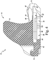
FIG. 4 is a cross-sectional view taken along the line 4-4 ofFIG. 3 , as viewed in the direction of the arrows; -
FIG. 5 is a view similar toFIG. 3 , but showing the post of tibial base trial captured in the channel of the tibial bearing trial, note the post is shown inFIG. 5 cut away from tibial base trial for clarity of description; -
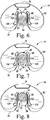
FIGS. 6-8 are diagrammatic bottom plan views of tibial bearing trial showing the post being captured in its channel so as to snap-lock the tibial bearing trial to the tibial base trial, note the post is shown cut away from tibial base trial for clarity of description inFIGS. 6-8 ; and -
FIG. 9 is an exploded perspective view showing the tibial base trial positioned on the surgically-prepared proximal end of a patient's tibia with the tibial bearing trial being installed there. - While the concepts of the present disclosure are susceptible to various modifications and alternative forms, specific exemplary embodiments thereof have been shown by way of example in the drawings and will herein be described in detail. It should be understood, however, that there is no intent to limit the concepts of the present disclosure to the particular forms disclosed, but on the contrary, the intention is to cover all modifications, equivalents, and alternatives falling within the spirit and scope of the invention as defined by the appended claims.
- Terms representing anatomical references, such as anterior, posterior, medial, lateral, superior, inferior, etcetera, may be used throughout the specification in reference to the orthopaedic implants or prostheses and surgical instruments described herein as well as in reference to the patient's natural anatomy. Such terms have well-understood meanings in both the study of anatomy and the field of orthopaedics. Use of such anatomical reference terms in the written description and claims is intended to be consistent with their well-understood meanings unless noted otherwise.
- Referring now to
FIG. 1 , an orthopaedicsurgical instrument system 10 includes atibial base trial 12 and atibial bearing trial 14 configured to be selectively coupled to thetibial base trial 12. Thetibial base trial 12 and thetibial bearing trial 14 may be utilized with a femoral component (seeFIG. 9 ) to size and select a tibial prosthesis for implantation into a patient's surgically-prepared tibia. In the illustrative embodiment, the femoral component may be a femoral trial component or a primary femoral component from a previous joint arthroplasty. It should be appreciated that theinstrument system 10 may include a number oftrial components - As described in greater detail below, the
tibial bearing trial 14 is configured to be removably secured to thetibial base trial 12. During a surgical procedure, the surgeon may evaluate the range of motion of the patient's leg with thetibial bearing trial 14 positioned in the knee joint to assess, amongst other things, the range of motion and stability of the knee. Thetibial bearing trial 14 is configured to be detached from thetibial base trial 12 during the surgical procedure and replaced with a tibial bearing trial of a different size to permit the surgeon to evaluate a range of possible implant sizes and select the one that provides the desired performance. - It should be appreciated that the
tibial bearing component 14 is embodied as a "mobile tibial bearing trial." As used herein, such a term refers to atibial bearing trial 14 that is permitted to rotate relative to thetibial base trial 12 when it is attached a tibialbase trial component 14. In other words, a mobile tibial bearing trial is configured to rotate relative to thetibial base trial 12 in the anterior-posterior direction and/or the medial-lateral direction. In the illustrative embodiment described herein, themobile bearing trial 14 is embodied as a revision trial. - The
tibial base trial 12 is configured to be positioned on a surgically-prepared proximal end of a patient's tibia. In the illustrative embodiment, thebase trial 12 includes aplate 20 shaped to be positioned on a proximal end of a patient's tibia. Theplate 20 has a substantially-planarsuperior surface 22, aninferior surface 24, and anouter side wall 26 extending between thesurfaces outer side wall 26 has ananterior section 30 and aposterior section 32 shaped to match a proximal end of a resected tibia. In the illustrative embodiment, theanterior section 30 of theside wall 26 is convexly curved, and theposterior section 32 is concavely curved. It should be appreciated that thetibial base trial 12 may be formed in a number of different sizes to accommodate tibias of various sizes. - The
tibial base trial 12 includes a captured lockingbolt 40 extending in the superior-inferior direction. The lockingbolt 40 has a threadedend 42 which extends downwardly from theinferior surface 24 of theplate 20. The threadedend 42 is sized to be received in a threaded bore (not shown) of a surgical instrument such as, for example, an elongated broach or stem trial component configured to be inserted in the intramedullary canal of the patient's tibia. The opposite end of the lockingbolt 40 has asocket 44 formed therein. Thesocket 44 is configured to receive a hex-head driver (not shown). Rotation of thesocket 44 with the hex-head driver causes rotation of the locking bolt's threadedend 42 thereby allowing thebolt 40, and hence thetibial base trial 12, to be secured to (and removed from) the elongated broach, stem trial, or other surgical instrument. Theplate 20 also includes a number of fastener guides 46 configured to receive a fastener, such as a fixation pin (not shown), which may be utilized to secure thetibial base trial 12 to the surgically-prepared proximal end of the patient's tibia. - The
tibial base trial 12 includes apost 48 that extends outwardly in the superior direction from thesuperior surface 22 of theplate 20 along alongitudinal axis 50. As will be described in more detail below, thepost 48 is configured to secure thetibial bearing trial 14 to thetibial base trial 12. Thepost 48 includes astem 52 extending superiorly from thesuperior surface 22 of theplate 20. An annular-shapedflange 54 extends outwardly from a distal end of thepost 48. As such, the post'sflange 54 has a larger diameter than itsstem 52. Aninferior surface 56 of theflange 54 faces thesuperior surface 22 of theplate 20. Agroove 58 is defined between theinferior surface 56 of theflange 54 and thesuperior surface 22 of theplate 20. As described below, a locking mechanism of thetibial bearing trial 14 is configured to engage thestem 52 of thepost 48 within thegroove 58. - As described above, the
tibial bearing trial 14 is configured to be selectively and removably coupled to thetibial base trial 12. As will be described in more detail below, thetibial bearing trial 14 may be anteriorly installed on, and uninstalled from, thetibial base trial 12 by moving it solely in the anterior-posterior direction without having to urge thetibial bearing trial 14 superiorly during either installation or detachment/removal thereof. As shown inFIG. 1 , thetibial bearing trial 14 includes abody 60 having a substantially-planarinferior surface 62 and an oppositesuperior surface 64. Theinferior surface 62 of thetibial bearing trial 14 is configured to abut thesuperior surface 22 of theplate 20 of thetibial base trial 12. Thesuperior surface 64 of thetibial bearing trial 14 includes a pair of curved bearing surfaces 66 configured to correspond to the condylar surfaces of a femoral component (seeFIG. 9 ). Aspine 70 is positioned between the curved bearing surfaces 66 and extends superiorly from thesuperior surface 64 of thetibial bearing trial 14. - The
tibial bearing trial 14 includes anouter sidewall 72 having ananterior section 74 that is shaped to match theanterior section 30 of thetibial base trial 12 and aposterior section 76 that is shaped to match theposterior section 32 of thetibial base trial 12. Referring toFIGS. 2-4 , achannel 80 is formed in theinferior surface 62 of thetibial bearing trial 14. The posterior end of thechannel 80 is defined by anopening 82 formed in theposterior section 76 of the bearing trial'souter sidewall 72. The anterior end of thechannel 80 is defined by arounded sidewall 84. In such a way, the anterior end of thechannel 80 defines around cavity 86. As can be seen inFIG. 2 , theinferior surface 62 of thetibial bearing trial 14 has a pair ofdeflectable flanges 88 formed therein. The medial and lateral sides of thechannel 80 are defined by themedial edges 90 of thedeflectable flanges 88. As can be seen inFIG. 2 , thechannel 80 extends in the anterior/posterior direction along alongitudinal axis 92. As such, thelongitudinal axis 92 of the channel is orthogonal to thelongitudinal axis 50 of the tibial base trial'spost 48. - As can be seen in
FIGS. 2-4 , theinferior surface 62 of thetibial bearing trial 14 also has an elongatedslot 94 formed therein. Like thechannel 80, the posterior end of theslot 94 is defined by anopening 96 formed in theposterior section 76 of the bearing trial'souter sidewall 72. Theslot 94 shares a common longitudinal axis with thechannel 80 and, as such, extends in anteriorly away from theopening 96 in the anterior/posterior direction along thelongitudinal axis 92. Theslot 94 is positioned superiorly of thechannel 80 and opens into it along its length. As can be seen inFIGS. 2-4 , theslot 94 is wider that thechannel 80, including theround cavity 86 defined in the channel's anterior end. As such, and as will be described in more detail below, theslot 94 is configured to receive the annular-shapedflange 54 of thepost 48 as the post'sstem 52 is received intochannel 80 during installation of thetibial bearing trial 14 onto thetibial base trial 12. As will be discussed in more detail below in regard toFIGS. 6-8 , the diameter of the annular-shapedflange 54 is greater than the width of thechannel 80. As such, thetibial bearing trial 14 is prevented from lifting off the tibial base trial 12 (i.e., lifting superiorly off the tibial base trial 12) once thetibial bearing trial 14 is installed thereto. - As shown in
FIG. 2 , themedial edges 90 of each of thedeflectable flanges 88 have acam lobe 100 defined therein. The cam lobes 100 extend inwardly (i.e., medially) into thechannel 80 toward one another. Thetips 102 of thecam lobes 100 are separated from each other by a distance that is less than the diameter of thestem 52 of thepost 48 of thetibial base trial 12. As such, during installation or detachment/removal of thetibial bearing trial 14, thestem 52 contacts thecam lobes 100 so as to deflect or otherwise urge thedeflectable flanges 88 laterally away from one another. Specifically, as can be seen inFIG. 2 , a pair ofelongated cavities 104 is formed in theinferior surface 62 of thetibial bearing trial 14. Thecavities 104 are positioned laterally adjacent to thelateral edges 106 of thedeflectable flanges 88. In such an arrangement, thelateral edges 106 of thedeflectable flanges 88 define the medial sides of thecavity 104 adjacent to it. - As can be seen in
FIGS. 5-8 , during installation of thetibial bearing trial 14 onto thetibial base trial 12, thestem 52 of the base trial'spost 48 is advanced into thechannel 80 through theopening 82 formed in theposterior section 76 of the bearing trial'souter sidewall 72 while the annular-shapedflange 54 of the base trial'spost 48 enters theslot 94 through theopening 96 formed in theposterior section 76 of the bearing trial'souter sidewall 72. As thetibial bearing trial 14 continues to be moved in the anterior-to-posterior direction, the outer surface of thestem 52 of the base trial'spost 48 advances into contact with the posterior cam surfaces 108 of thecam lobes 100 thereby causing thedeflectable flanges 88 to deflect or otherwise be urged laterally away from one another. Thedeflectable flanges 88 continue to deflect as thestem 52 rides up the posterior cam surfaces 108. Once thestem 52 passes thetips 102 of thecam lobes 100, thestem 52 begins to ride down the anterior cam surfaces 110 of thecam lobes 100 thereby allowing thedeflectable flanges 88 to move medially back toward one another. Once thestem 52 clears the anterior cam surfaces 110, thedeflectable flanges 88 are retracted/returned to their original positions thereby capturing thestem 52 of the base trial'spost 48 in theround cavity 86 of thechannel 80 so as to snap-lock thetibial bearing trial 14 to thetibial base trial 12. - To detach the
tibial bearing trial 14 to thetibial base trial 12, the bearingtrial 14 is pulled or otherwise advanced in the posterior-to-anterior direction relative to thebase trial 12. Doing so causes the outer surface of thestem 52 of the base trial'spost 48 to be advanced into contact with the anterior cam surfaces 110 of thecam lobes 100 thereby causing thedeflectable flanges 88 to deflect or otherwise be urged laterally away from one another. Thedeflectable flanges 88 continue to deflect as thestem 52 rides up the anterior cam surfaces 110. Once thestem 52 passes thetips 102 of thecam lobes 100, thestem 52 begins to ride down the posterior cam surfaces 108 of thecam lobes 100 thereby allowing thedeflectable flanges 88 to move medially back toward one another. Once thestem 52 clears the posterior cam surfaces 108, thedeflectable flanges 88 are retracted/returned to their original positions thereby allowing thestem 52 of the base trial'spost 48 to be advanced out of thechannel 80 through theopening 82 formed in theposterior section 76 of the bearing trial'souter sidewall 72 while the annular-shapedflange 54 of the base trial'spost 48 exits theslot 94 through theopening 96 formed in theposterior section 76 of the bearing trial'souter sidewall 72 so as to detach thetibial bearing trial 14 from thetibial base trial 12. - The illustrated
tibial bearing trial 14 is one of a plurality of tibial bearing trials that make a multi-piece system configured to assist the surgeon in selecting a size and configuration of the implanted tibial bearing component. As such, the surgeon is able to assemble atibial bearing trial 14 of one size and configuration, evaluate the performance of thattibial bearing trial 14, and then replace it with a differenttibial bearing trial 14 as necessary to determine intraoperatively the type and configuration of the tibial bearing component to be implanted. - The
tibial base trial 12 is illustratively formed from a metallic material such as cobalt-chromium or titanium, but may be formed from other materials, such as a ceramic material, a polymer material, a bio-engineered material, or the like. Thetibial bearing trial 14 is illustratively formed from a polymer material such as an ultra-high molecular weight polyethylene (UHMWPE), but may be formed from other materials, such as a ceramic material, a metallic material, a bio-engineered material, or the like. - Referring now to
FIG. 9 , a surgeon may use the orthopaedicsurgical instrument system 10 during the trialing process of a surgical procedure to implant a knee prosthesis. To do so, the surgeon initially resects or otherwise surgically-prepares the patient'stibia 120 to form a smoothplanar surface 122 on aproximal end 124 of thetibia 120. The surgeon then installs thetibial base trial 12 on the resectedplanar surface 122 of the patient'stibia 120. If needed, the surgeon may also perform a resection of thedistal end 134 of the patient'sfemur 130 to surgically prepare the femur to receive afemoral trial 136 for use in a trial reduction procedure. In an embodiment in which a primary femoral component (not shown) from a previous joint arthroplasty is not being replaced, the surgeon may trial thetibial bearing trial 14 with the primary femoral component. - Once the
tibial base trial 12 has been installed on the resectedplanar surface 122 of the patient'stibia 120, the surgeon installs thetibial bearing trial 14 to thebase trial 12 from the anterior side of the patient'stibia 120. To do so, thetibial bearing trial 14 is first aligned with thetibial base trial 12 such that the posterior-most edge of theinferior surface 62 of thebearing trial 14 is positioned on thesuperior surface 22 on the anterior portion of the base trial'splate 20. Thetibial bearing trial 14 is then advanced onto thetibial base trial 12 in the anterior-to-posterior direction such that thestem 52 of the base trial'spost 48 is advanced into thechannel 80 through theopening 82 formed in theposterior section 76 of the bearing trial'souter sidewall 72 while the annular-shapedflange 54 of the base trial'spost 48 enters theslot 94 through theopening 96 formed in theposterior section 76 of the bearing trial'souter sidewall 72. As thetibial bearing trial 14 continues to be moved in the anterior-to-posterior direction, thestem 52 of the base trial'spost 48 advances into contact with thecam lobes 100 of the bearing's trial'sdeflectable flanges 88 thereby causing thedeflectable flanges 88 to initially deflect to allow thestem 52 to pass and thereafter retract back into their original positions thereby capturing thestem 52 of the base trial'spost 48 in theround cavity 86 of thechannel 80 so as to snap-lock thetibial bearing trial 14 to thetibial base trial 12. - It should be appreciated that during such installation of the
tibial bearing trial 14, the bearingtrial 14 is advanced solely in the anterior-to-posterior direction without having to be urged superiorly in any amount whatsoever. Specifically, the posterior-most edge of the bearing trial'sinferior surface 62 remains in contact with thesuperior surface 22 of the base trial'splate 20 throughout installation of thetibial bearing trial 14. - It should be appreciated that when installed on the
tibial base trial 12, thestem 52 and the annular-shapedflange 54 of the base trial's post are positioned in the rounded anterior ends of the bearing trial'schannel 80 andslot 94, respectively. As such, thetibial bearing trial 14 is free to rotate relative to thetibial base trial 12 when its snap-locked thereto. However, because the diameter of the annular-shapedflange 54 of the base trial'spost 48 is larger than the width of thechannel 80, thedeflectable flanges 88 of thetibial bearing trial 14 are captured in thegroove 58 defined between theinferior surface 56 of theflange 54 and thesuperior surface 22 of theplate 20. As such, whiletibial bearing trial 14 is free to rotate relative to thetibial base trial 12, it is prevented from lifting off ofbase trial 12. That is, thetibial bearing trial 14 is prevented from moving in the inferior-superior direction when it is snap-locked to thetibial base trial 12. - Once the
tibial bearing trial 14 is snap-locked to thetibial base trial 12, the surgeon may perform an initial trial reduction with theinstrument system 10. In doing so, the surgeon uses theinstrument system 10 to evaluate the stability and kinematics of the patient'sfemur 130 andtibia 120. To do so, the surgeon moves the patient'stibia 120 relative to the patient'sfemur 130 between full flexion and full extension. During such movement of the patient's knee, the surgeon evaluates the articulation of the femoral trial 136 (or the primary femoral component (not shown) from a previous joint arthroplasty if it is not being replaced) and thetibial bearing trial 14 to determine, amongst other things, desired contact points between the two trials, range of motion, and cam/spine engagement. - If the surgeon desires to try a different size or configuration of the
tibial bearing trial 14, the surgeon detaches the installed bearingtrial 14 by pulling or otherwise advancing the bearingtrial 14 in the posterior-to-anterior direction relative to thebase trial 12. Doing so causes thestem 52 of the base trial'spost 48 to be advanced into contact with thecam lobes 100 thereby causing thedeflectable flanges 88 to initially deflect to allow thestem 52 to pass and thereafter retract back into their original positions thereby allowing thestem 52 of the base trial'spost 48 to be advanced out of thechannel 80 through theopening 82 formed in theposterior section 76 of the bearing trial'souter sidewall 72 while the annular-shapedflange 54 of the base trial'spost 48 exits theslot 94 through theopening 96 formed in theposterior section 76 of the bearing trial'souter sidewall 72 so as to detach thetibial bearing trial 14 from thetibial base trial 12. - Thereafter, the surgeon may install a different
tibial bearing trial 14 on thetibial base trial 12 in the manner described above. With the secondtibial bearing trial 14 installed, the surgeon may then perform a subsequent trial reduction in the manner described above. - Once the desired size and configuration of the
tibial base trial 12 and thetibial bearing trial 14 have been determined by the surgeon, thetrials tibia 12 and the corresponding implant components are implanted in the patient'stibia 12. - While the disclosure has been illustrated and described in detail in the drawings and foregoing description, such an illustration and description is to be considered as exemplary and not restrictive in character, it being understood that only illustrative embodiments have been shown and described and that all changes and modifications that come within the spirit of the disclosure are desired to be protected.
- There are a plurality of advantages of the present disclosure arising from the various features of the method, apparatus, and system described herein. It will be noted that alternative embodiments of the method, apparatus, and system of the present disclosure may not include all of the features described yet still benefit from at least some of the advantages of such features. Those of ordinary skill in the art may readily devise their own implementations of the method, apparatus, and system that incorporate one or more of the features of the present invention and fall within the spirit and scope of the present disclosure as defined by the appended claims.
Claims (14)
- An orthopaedic surgical instrument system, comprising:a tibial bearing trial including (i) an inferior surface, (ii) a superior surface opposite the inferior surface and having a pair of curved bearing surfaces formed therein, (iii) a sidewall extending between the inferior surface and the superior surface, and (iv) a channel formed in the inferior surface, wherein (a) a posterior end of the channel is defined by an opening formed in a posterior section of the sidewall, (b) an anterior end of the channel is defined by a rounded sidewall so as to define a round cavity, and (c) medial and lateral sides of the channel are defined by a pair of deflectable flanges, anda tibial base trial removeably coupled to the trial insert trial, the tibial base trial including (i) a plate configured to be positioned on a surgically-prepared proximal end of a patient's tibia, and (ii) a post extending outwardly from a superior surface of the plate, wherein the post is captured in the round cavity of the channel of the tibial bearing trial so as to allow the tibial bearing trial to rotate relative to the tibial base trial, but prevent movement of the tibial bearing trial in an inferior-superior direction relative to the tibial base trial.
- The orthopaedic surgical instrument system of claim 1, wherein the tibial bearing trial includes a spine positioned between the pair of curved bearing surfaces.
- The orthopaedic surgical instrument system of claim 1, wherein:the tibial bearing trial further includes an elongated slot formed therein, the elongated slot having a common longitudinal axis with the channel,the elongated slot is positioned superiorly of the channel and opens into the channel,the post of the tibial base trial has an annular-shaped flange extending outwardly therefrom, andthe flange of the post is captured in the slot.
- The orthopaedic surgical instrument system of claim 3, wherein:a posterior end of the slot is defined by the opening formed in the posterior section of the sidewall, andthe slot is wider than the diameter of the round cavity of the channel.
- The orthopaedic surgical instrument system of claim 1, wherein:each of the pair of deflectable flanges has a cam lobe formed therein, andthe cam lobes extend inwardly into the channel toward one another.
- The orthopaedic surgical instrument system of claim 5, wherein the cam lobes are separated from one another by a distance that is less than the diameter of the post of the tibial base trial.
- The orthopaedic surgical instrument system of claim 1, wherein:each of the deflectable flanges has an elongated cavity formed laterally adjacent thereto, anda lateral edge of each of the deflectable flanges is urged into a corresponding one of the elongated cavities when the post of the tibial base trial contacts the cam lobes so as to urge the cam lobes away from one another.
- The orthopaedic surgical instrument system of claim 1, wherein the tibial bearing trial is constructed of a polymeric material.
- An orthopaedic surgical instrument, comprising:
a tibial bearing trial, comprising:an inferior surface,a superior surface opposite the inferior surface and having a pair of curved bearing surfaces formed therein,a spine positioned between the pair of curved bearing surfaces,a sidewall extending between the inferior surface and the superior surface, anda channel formed in the inferior surface, wherein (i) a posterior end of the channel is defined by an opening formed in a posterior section of the sidewall, (ii) an anterior end of the channel is defined by a rounded sidewall so as to define a round cavity, and (iii) medial and lateral sides of the channel are defined by a pair of deflectable flanges. - The orthopaedic surgical instrument of claim 9, wherein:the tibial bearing trial further includes an elongated slot formed therein, the elongated slot having a common longitudinal axis with the channel, andthe elongated slot is positioned superiorly of the channel and opens into the channel.
- The orthopaedic surgical instrument of claim 10, wherein:a posterior end of the slot is defined by the opening formed in the posterior section of the sidewall, andthe slot is wider than the diameter of the round cavity of the channel.
- The orthopaedic surgical instrument of claim 9, wherein:each of the pair of deflectable flanges has a cam lobe formed therein, andthe cam lobes extend inwardly into the channel toward one another.
- The orthopaedic surgical instrument of claim 12, wherein:each of the deflectable flanges has an elongated cavity formed laterally adjacent thereto, anda lateral edge of each of the deflectable flanges is urged into a corresponding one of the elongated cavities when the cam lobes are contacted during installation of the tibial bearing trial onto a tibial base trial.
- The orthopaedic surgical instrument of claim 9, wherein the tibial bearing trial is constructed of a polymeric material.
Applications Claiming Priority (1)
| Application Number | Priority Date | Filing Date | Title |
|---|---|---|---|
| US16/707,425 US11633294B2 (en) | 2019-12-09 | 2019-12-09 | Orthopaedic surgical instrument system having an anterior-loading tibial bearing trial and associated surgical method of using the same |
Publications (2)
| Publication Number | Publication Date |
|---|---|
| EP3834779A1 true EP3834779A1 (en) | 2021-06-16 |
| EP3834779B1 EP3834779B1 (en) | 2025-03-05 |
Family
ID=73789805
Family Applications (1)
| Application Number | Title | Priority Date | Filing Date |
|---|---|---|---|
| EP20212564.7A Active EP3834779B1 (en) | 2019-12-09 | 2020-12-08 | Orthopaedic surgical instrument system having an anterior-loading tibial bearing trial and associated surgical method of using the same |
Country Status (7)
| Country | Link |
|---|---|
| US (1) | US11633294B2 (en) |
| EP (1) | EP3834779B1 (en) |
| JP (1) | JP7654392B2 (en) |
| CN (1) | CN113017933A (en) |
| AU (1) | AU2020281005B2 (en) |
| BR (1) | BR102020023864A2 (en) |
| CA (1) | CA3100418A1 (en) |
Citations (4)
| Publication number | Priority date | Publication date | Assignee | Title |
|---|---|---|---|---|
| EP1186277A2 (en) * | 1996-05-28 | 2002-03-13 | Howmedica International Inc. | Tibial element for a replacement knee prosthesis |
| EP2939615A1 (en) * | 2014-04-30 | 2015-11-04 | DePuy (Ireland) | Tibial trial system for a knee prosthesis |
| US20170049582A1 (en) * | 2015-08-19 | 2017-02-23 | Depuy Ireland Unlimited Company | Trial kit for knee prosthesis system |
| EP3545911A1 (en) * | 2018-03-27 | 2019-10-02 | DePuy Ireland Unlimited Company | Orthopaedic surgical instrument system and a method of trialing an orthopaedic prosthetic assembly |
Family Cites Families (24)
| Publication number | Priority date | Publication date | Assignee | Title |
|---|---|---|---|---|
| GB9611059D0 (en) * | 1996-05-28 | 1996-07-31 | Howmedica | Tibial element for a replacement knee prosthesis |
| GB9705172D0 (en) | 1997-03-13 | 1997-04-30 | Zimmer Limited | Evaluating the fit of an orthopaedic implant |
| US6126692A (en) * | 1998-06-25 | 2000-10-03 | New York Society For The Relief Of The Ruptured And Crippled Maintaining The Hospital For Special Surgery | Retaining mechanism for a modular tibial component of a knee prosthesis |
| US6217618B1 (en) * | 1999-10-26 | 2001-04-17 | Bristol-Myers Squibb Company | Tibial knee component with a mobile bearing |
| US20040162619A1 (en) | 2001-08-27 | 2004-08-19 | Zimmer Technology, Inc. | Tibial augments for use with knee joint prostheses, method of implanting the tibial augment, and associated tools |
| US6916324B2 (en) | 2003-02-04 | 2005-07-12 | Zimmer Technology, Inc. | Provisional orthopedic prosthesis for partially resected bone |
| WO2006088684A1 (en) | 2005-02-17 | 2006-08-24 | Zimmer Technology, Inc. | Tibial trialing assembly and method of trialing a tibial implant |
| AU2007286743B2 (en) * | 2006-08-22 | 2013-05-09 | Exactech, Inc. | System and method for adjusting the thickness of a prosthesis |
| US7691150B2 (en) | 2006-12-15 | 2010-04-06 | Zimmer Technology, Inc. | Modular plate and keel provisionals |
| US8128703B2 (en) * | 2007-09-28 | 2012-03-06 | Depuy Products, Inc. | Fixed-bearing knee prosthesis having interchangeable components |
| US7628818B2 (en) * | 2007-09-28 | 2009-12-08 | Depuy Products, Inc. | Fixed-bearing knee prosthesis having interchangeable components |
| WO2010088229A2 (en) | 2009-01-27 | 2010-08-05 | Zimmer, Inc. | Total knee implant |
| US8771280B2 (en) | 2010-03-08 | 2014-07-08 | Zimmer, Inc. | Femoral cut guide |
| WO2012018563A1 (en) * | 2010-07-24 | 2012-02-09 | Zimmer, Inc. | Tibial prosthesis |
| US8603101B2 (en) | 2010-12-17 | 2013-12-10 | Zimmer, Inc. | Provisional tibial prosthesis system |
| US9597090B2 (en) | 2010-12-17 | 2017-03-21 | Zimmer, Inc. | Cut guide attachment for use in tibial prosthesis systems |
| US8551179B2 (en) | 2011-06-16 | 2013-10-08 | Zimmer, Inc. | Femoral prosthesis system having provisional component with visual indicators |
| US20130006378A1 (en) * | 2011-06-30 | 2013-01-03 | Wogoman Thomas E | Polymer femoral trial component |
| US9814584B2 (en) * | 2011-09-28 | 2017-11-14 | Depuy Ireland Unlimited Company | Fixed-bearing knee prosthesis having a locking mechanism with a concave-to-convex mating interface |
| US20130261759A1 (en) | 2012-03-30 | 2013-10-03 | Zimmer, Inc. | Tibial prosthesis systems, kits, and methods |
| EP2849684B1 (en) | 2012-05-08 | 2016-05-25 | Zimmer, Inc. | Instruments for foot and ankle fusion |
| US9925052B2 (en) | 2013-08-30 | 2018-03-27 | Zimmer, Inc. | Method for optimizing implant designs |
| EP2918235B1 (en) | 2013-10-25 | 2017-01-04 | Zimmer, Inc. | Cut guide attachment for use in tibial prosthesis systems |
| US11020131B2 (en) | 2016-10-14 | 2021-06-01 | Zimmer, Inc. | Multi-use tool |
-
2019
- 2019-12-09 US US16/707,425 patent/US11633294B2/en active Active
-
2020
- 2020-11-23 BR BR102020023864-7A patent/BR102020023864A2/en not_active Application Discontinuation
- 2020-11-23 CA CA3100418A patent/CA3100418A1/en active Pending
- 2020-11-30 AU AU2020281005A patent/AU2020281005B2/en active Active
- 2020-12-08 JP JP2020203203A patent/JP7654392B2/en active Active
- 2020-12-08 EP EP20212564.7A patent/EP3834779B1/en active Active
- 2020-12-09 CN CN202011427703.4A patent/CN113017933A/en active Pending
Patent Citations (4)
| Publication number | Priority date | Publication date | Assignee | Title |
|---|---|---|---|---|
| EP1186277A2 (en) * | 1996-05-28 | 2002-03-13 | Howmedica International Inc. | Tibial element for a replacement knee prosthesis |
| EP2939615A1 (en) * | 2014-04-30 | 2015-11-04 | DePuy (Ireland) | Tibial trial system for a knee prosthesis |
| US20170049582A1 (en) * | 2015-08-19 | 2017-02-23 | Depuy Ireland Unlimited Company | Trial kit for knee prosthesis system |
| EP3545911A1 (en) * | 2018-03-27 | 2019-10-02 | DePuy Ireland Unlimited Company | Orthopaedic surgical instrument system and a method of trialing an orthopaedic prosthetic assembly |
Also Published As
| Publication number | Publication date |
|---|---|
| CA3100418A1 (en) | 2021-06-09 |
| AU2020281005B2 (en) | 2025-10-09 |
| US20210169664A1 (en) | 2021-06-10 |
| EP3834779B1 (en) | 2025-03-05 |
| AU2020281005A1 (en) | 2021-06-24 |
| BR102020023864A2 (en) | 2021-06-22 |
| US11633294B2 (en) | 2023-04-25 |
| JP7654392B2 (en) | 2025-04-01 |
| CN113017933A (en) | 2021-06-25 |
| JP2021090747A (en) | 2021-06-17 |
Similar Documents
| Publication | Publication Date | Title |
|---|---|---|
| EP2140838B1 (en) | Tibial bearing for a knee joint prosthesis | |
| US9132011B2 (en) | Femoral trial component | |
| EP2143403A1 (en) | Knee Prosthesis | |
| AU2019202948B2 (en) | Orthopaedic prosthetic system for a hinged knee prosthesis | |
| US11696834B2 (en) | Orthopaedic prosthetic system for a rotating hinged-knee prosthesis | |
| US11141291B2 (en) | Femoral trial components and associated orthopaedic surgical method of use | |
| US20240099859A1 (en) | Method of trialing an orthopaedic prosthetic assembly | |
| US11116641B2 (en) | Orthopaedic prosthetic system for a rotating hinged-knee prosthesis | |
| US9861485B2 (en) | Reverse knee prosthesis | |
| EP3834779B1 (en) | Orthopaedic surgical instrument system having an anterior-loading tibial bearing trial and associated surgical method of using the same | |
| EP3692951B1 (en) | Orthopaedic prosthetic system for a rotating hinged-knee prosthesis |
Legal Events
| Date | Code | Title | Description |
|---|---|---|---|
| PUAI | Public reference made under article 153(3) epc to a published international application that has entered the european phase |
Free format text: ORIGINAL CODE: 0009012 |
|
| STAA | Information on the status of an ep patent application or granted ep patent |
Free format text: STATUS: THE APPLICATION HAS BEEN PUBLISHED |
|
| AK | Designated contracting states |
Kind code of ref document: A1 Designated state(s): AL AT BE BG CH CY CZ DE DK EE ES FI FR GB GR HR HU IE IS IT LI LT LU LV MC MK MT NL NO PL PT RO RS SE SI SK SM TR |
|
| STAA | Information on the status of an ep patent application or granted ep patent |
Free format text: STATUS: REQUEST FOR EXAMINATION WAS MADE |
|
| 17P | Request for examination filed |
Effective date: 20211214 |
|
| RBV | Designated contracting states (corrected) |
Designated state(s): AL AT BE BG CH CY CZ DE DK EE ES FI FR GB GR HR HU IE IS IT LI LT LU LV MC MK MT NL NO PL PT RO RS SE SI SK SM TR |
|
| GRAP | Despatch of communication of intention to grant a patent |
Free format text: ORIGINAL CODE: EPIDOSNIGR1 |
|
| STAA | Information on the status of an ep patent application or granted ep patent |
Free format text: STATUS: GRANT OF PATENT IS INTENDED |
|
| INTG | Intention to grant announced |
Effective date: 20241008 |
|
| GRAS | Grant fee paid |
Free format text: ORIGINAL CODE: EPIDOSNIGR3 |
|
| GRAA | (expected) grant |
Free format text: ORIGINAL CODE: 0009210 |
|
| STAA | Information on the status of an ep patent application or granted ep patent |
Free format text: STATUS: THE PATENT HAS BEEN GRANTED |
|
| AK | Designated contracting states |
Kind code of ref document: B1 Designated state(s): AL AT BE BG CH CY CZ DE DK EE ES FI FR GB GR HR HU IE IS IT LI LT LU LV MC MK MT NL NO PL PT RO RS SE SI SK SM TR |
|
| REG | Reference to a national code |
Ref country code: GB Ref legal event code: FG4D |
|
| REG | Reference to a national code |
Ref country code: CH Ref legal event code: EP |
|
| REG | Reference to a national code |
Ref country code: IE Ref legal event code: FG4D |
|
| REG | Reference to a national code |
Ref country code: DE Ref legal event code: R096 Ref document number: 602020047122 Country of ref document: DE |
|
| PG25 | Lapsed in a contracting state [announced via postgrant information from national office to epo] |
Ref country code: RS Free format text: LAPSE BECAUSE OF FAILURE TO SUBMIT A TRANSLATION OF THE DESCRIPTION OR TO PAY THE FEE WITHIN THE PRESCRIBED TIME-LIMIT Effective date: 20250605 |
|
| PG25 | Lapsed in a contracting state [announced via postgrant information from national office to epo] |
Ref country code: FI Free format text: LAPSE BECAUSE OF FAILURE TO SUBMIT A TRANSLATION OF THE DESCRIPTION OR TO PAY THE FEE WITHIN THE PRESCRIBED TIME-LIMIT Effective date: 20250305 |
|
| REG | Reference to a national code |
Ref country code: NL Ref legal event code: MP Effective date: 20250305 |
|
| PG25 | Lapsed in a contracting state [announced via postgrant information from national office to epo] |
Ref country code: ES Free format text: LAPSE BECAUSE OF FAILURE TO SUBMIT A TRANSLATION OF THE DESCRIPTION OR TO PAY THE FEE WITHIN THE PRESCRIBED TIME-LIMIT Effective date: 20250305 |
|
| REG | Reference to a national code |
Ref country code: LT Ref legal event code: MG9D |
|
| PG25 | Lapsed in a contracting state [announced via postgrant information from national office to epo] |
Ref country code: NO Free format text: LAPSE BECAUSE OF FAILURE TO SUBMIT A TRANSLATION OF THE DESCRIPTION OR TO PAY THE FEE WITHIN THE PRESCRIBED TIME-LIMIT Effective date: 20250605 |
|
| PG25 | Lapsed in a contracting state [announced via postgrant information from national office to epo] |
Ref country code: HR Free format text: LAPSE BECAUSE OF FAILURE TO SUBMIT A TRANSLATION OF THE DESCRIPTION OR TO PAY THE FEE WITHIN THE PRESCRIBED TIME-LIMIT Effective date: 20250305 |
|
| PG25 | Lapsed in a contracting state [announced via postgrant information from national office to epo] |
Ref country code: LV Free format text: LAPSE BECAUSE OF FAILURE TO SUBMIT A TRANSLATION OF THE DESCRIPTION OR TO PAY THE FEE WITHIN THE PRESCRIBED TIME-LIMIT Effective date: 20250305 |
|
| PG25 | Lapsed in a contracting state [announced via postgrant information from national office to epo] |
Ref country code: GR Free format text: LAPSE BECAUSE OF FAILURE TO SUBMIT A TRANSLATION OF THE DESCRIPTION OR TO PAY THE FEE WITHIN THE PRESCRIBED TIME-LIMIT Effective date: 20250606 Ref country code: BG Free format text: LAPSE BECAUSE OF FAILURE TO SUBMIT A TRANSLATION OF THE DESCRIPTION OR TO PAY THE FEE WITHIN THE PRESCRIBED TIME-LIMIT Effective date: 20250305 |
|
| REG | Reference to a national code |
Ref country code: AT Ref legal event code: MK05 Ref document number: 1772222 Country of ref document: AT Kind code of ref document: T Effective date: 20250305 |
|
| PG25 | Lapsed in a contracting state [announced via postgrant information from national office to epo] |
Ref country code: NL Free format text: LAPSE BECAUSE OF FAILURE TO SUBMIT A TRANSLATION OF THE DESCRIPTION OR TO PAY THE FEE WITHIN THE PRESCRIBED TIME-LIMIT Effective date: 20250305 |
|
| PG25 | Lapsed in a contracting state [announced via postgrant information from national office to epo] |
Ref country code: SE Free format text: LAPSE BECAUSE OF FAILURE TO SUBMIT A TRANSLATION OF THE DESCRIPTION OR TO PAY THE FEE WITHIN THE PRESCRIBED TIME-LIMIT Effective date: 20250305 |
|
| PG25 | Lapsed in a contracting state [announced via postgrant information from national office to epo] |
Ref country code: SM Free format text: LAPSE BECAUSE OF FAILURE TO SUBMIT A TRANSLATION OF THE DESCRIPTION OR TO PAY THE FEE WITHIN THE PRESCRIBED TIME-LIMIT Effective date: 20250305 |
|
| PG25 | Lapsed in a contracting state [announced via postgrant information from national office to epo] |
Ref country code: PT Free format text: LAPSE BECAUSE OF FAILURE TO SUBMIT A TRANSLATION OF THE DESCRIPTION OR TO PAY THE FEE WITHIN THE PRESCRIBED TIME-LIMIT Effective date: 20250707 |
|
| PG25 | Lapsed in a contracting state [announced via postgrant information from national office to epo] |
Ref country code: IT Free format text: LAPSE BECAUSE OF FAILURE TO SUBMIT A TRANSLATION OF THE DESCRIPTION OR TO PAY THE FEE WITHIN THE PRESCRIBED TIME-LIMIT Effective date: 20250305 Ref country code: PL Free format text: LAPSE BECAUSE OF FAILURE TO SUBMIT A TRANSLATION OF THE DESCRIPTION OR TO PAY THE FEE WITHIN THE PRESCRIBED TIME-LIMIT Effective date: 20250305 |
|
| PG25 | Lapsed in a contracting state [announced via postgrant information from national office to epo] |
Ref country code: AT Free format text: LAPSE BECAUSE OF FAILURE TO SUBMIT A TRANSLATION OF THE DESCRIPTION OR TO PAY THE FEE WITHIN THE PRESCRIBED TIME-LIMIT Effective date: 20250305 |
|
| PG25 | Lapsed in a contracting state [announced via postgrant information from national office to epo] |
Ref country code: EE Free format text: LAPSE BECAUSE OF FAILURE TO SUBMIT A TRANSLATION OF THE DESCRIPTION OR TO PAY THE FEE WITHIN THE PRESCRIBED TIME-LIMIT Effective date: 20250305 Ref country code: CZ Free format text: LAPSE BECAUSE OF FAILURE TO SUBMIT A TRANSLATION OF THE DESCRIPTION OR TO PAY THE FEE WITHIN THE PRESCRIBED TIME-LIMIT Effective date: 20250305 |
|
| PG25 | Lapsed in a contracting state [announced via postgrant information from national office to epo] |
Ref country code: RO Free format text: LAPSE BECAUSE OF FAILURE TO SUBMIT A TRANSLATION OF THE DESCRIPTION OR TO PAY THE FEE WITHIN THE PRESCRIBED TIME-LIMIT Effective date: 20250305 |
|
| PG25 | Lapsed in a contracting state [announced via postgrant information from national office to epo] |
Ref country code: SK Free format text: LAPSE BECAUSE OF FAILURE TO SUBMIT A TRANSLATION OF THE DESCRIPTION OR TO PAY THE FEE WITHIN THE PRESCRIBED TIME-LIMIT Effective date: 20250305 |
|
| PG25 | Lapsed in a contracting state [announced via postgrant information from national office to epo] |
Ref country code: IS Free format text: LAPSE BECAUSE OF FAILURE TO SUBMIT A TRANSLATION OF THE DESCRIPTION OR TO PAY THE FEE WITHIN THE PRESCRIBED TIME-LIMIT Effective date: 20250705 |
|
| REG | Reference to a national code |
Ref country code: DE Ref legal event code: R097 Ref document number: 602020047122 Country of ref document: DE |
|
| PGFP | Annual fee paid to national office [announced via postgrant information from national office to epo] |
Ref country code: DE Payment date: 20251028 Year of fee payment: 6 |
|
| PGFP | Annual fee paid to national office [announced via postgrant information from national office to epo] |
Ref country code: GB Payment date: 20251030 Year of fee payment: 6 |
|
| PLBE | No opposition filed within time limit |
Free format text: ORIGINAL CODE: 0009261 |
|
| STAA | Information on the status of an ep patent application or granted ep patent |
Free format text: STATUS: NO OPPOSITION FILED WITHIN TIME LIMIT |
|
| PG25 | Lapsed in a contracting state [announced via postgrant information from national office to epo] |
Ref country code: DK Free format text: LAPSE BECAUSE OF FAILURE TO SUBMIT A TRANSLATION OF THE DESCRIPTION OR TO PAY THE FEE WITHIN THE PRESCRIBED TIME-LIMIT Effective date: 20250305 |
|
| REG | Reference to a national code |
Ref country code: CH Ref legal event code: L10 Free format text: ST27 STATUS EVENT CODE: U-0-0-L10-L00 (AS PROVIDED BY THE NATIONAL OFFICE) Effective date: 20260114 |
|
| 26N | No opposition filed |
Effective date: 20251208 |