EP3834664B1 - Three-section synchronous slide rail - Google Patents
Three-section synchronous slide rail Download PDFInfo
- Publication number
- EP3834664B1 EP3834664B1 EP19853059.4A EP19853059A EP3834664B1 EP 3834664 B1 EP3834664 B1 EP 3834664B1 EP 19853059 A EP19853059 A EP 19853059A EP 3834664 B1 EP3834664 B1 EP 3834664B1
- Authority
- EP
- European Patent Office
- Prior art keywords
- connector
- flexible deflector
- rope base
- flexible
- rail
- Prior art date
- Legal status (The legal status is an assumption and is not a legal conclusion. Google has not performed a legal analysis and makes no representation as to the accuracy of the status listed.)
- Active
Links
Images



Classifications
-
- F—MECHANICAL ENGINEERING; LIGHTING; HEATING; WEAPONS; BLASTING
- F16—ENGINEERING ELEMENTS AND UNITS; GENERAL MEASURES FOR PRODUCING AND MAINTAINING EFFECTIVE FUNCTIONING OF MACHINES OR INSTALLATIONS; THERMAL INSULATION IN GENERAL
- F16C—SHAFTS; FLEXIBLE SHAFTS; ELEMENTS OR CRANKSHAFT MECHANISMS; ROTARY BODIES OTHER THAN GEARING ELEMENTS; BEARINGS
- F16C29/00—Bearings for parts moving only linearly
- F16C29/008—Systems with a plurality of bearings, e.g. four carriages supporting a slide on two parallel rails
-
- A—HUMAN NECESSITIES
- A47—FURNITURE; DOMESTIC ARTICLES OR APPLIANCES; COFFEE MILLS; SPICE MILLS; SUCTION CLEANERS IN GENERAL
- A47B—TABLES; DESKS; OFFICE FURNITURE; CABINETS; DRAWERS; GENERAL DETAILS OF FURNITURE
- A47B88/00—Drawers for tables, cabinets or like furniture; Guides for drawers
- A47B88/40—Sliding drawers; Slides or guides therefor
- A47B88/44—Sequencing or synchronisation of drawer slides or functional units
- A47B88/447—Simultaneous movement of rails within drawer slides, i.e. with a coordination of movement with all rail elements moving at the same time
-
- A—HUMAN NECESSITIES
- A47—FURNITURE; DOMESTIC ARTICLES OR APPLIANCES; COFFEE MILLS; SPICE MILLS; SUCTION CLEANERS IN GENERAL
- A47B—TABLES; DESKS; OFFICE FURNITURE; CABINETS; DRAWERS; GENERAL DETAILS OF FURNITURE
- A47B88/00—Drawers for tables, cabinets or like furniture; Guides for drawers
- A47B88/40—Sliding drawers; Slides or guides therefor
- A47B88/44—Sequencing or synchronisation of drawer slides or functional units
- A47B88/45—Synchronisation of cooperating drawer slides, i.e. with a coordination of the rail movement of different drawer slides
-
- A—HUMAN NECESSITIES
- A47—FURNITURE; DOMESTIC ARTICLES OR APPLIANCES; COFFEE MILLS; SPICE MILLS; SUCTION CLEANERS IN GENERAL
- A47B—TABLES; DESKS; OFFICE FURNITURE; CABINETS; DRAWERS; GENERAL DETAILS OF FURNITURE
- A47B88/00—Drawers for tables, cabinets or like furniture; Guides for drawers
- A47B88/40—Sliding drawers; Slides or guides therefor
- A47B88/49—Sliding drawers; Slides or guides therefor with double extensible guides or parts
-
- A—HUMAN NECESSITIES
- A47—FURNITURE; DOMESTIC ARTICLES OR APPLIANCES; COFFEE MILLS; SPICE MILLS; SUCTION CLEANERS IN GENERAL
- A47B—TABLES; DESKS; OFFICE FURNITURE; CABINETS; DRAWERS; GENERAL DETAILS OF FURNITURE
- A47B88/00—Drawers for tables, cabinets or like furniture; Guides for drawers
- A47B88/40—Sliding drawers; Slides or guides therefor
- A47B88/49—Sliding drawers; Slides or guides therefor with double extensible guides or parts
- A47B88/493—Sliding drawers; Slides or guides therefor with double extensible guides or parts with rollers, ball bearings, wheels, or the like
-
- F—MECHANICAL ENGINEERING; LIGHTING; HEATING; WEAPONS; BLASTING
- F16—ENGINEERING ELEMENTS AND UNITS; GENERAL MEASURES FOR PRODUCING AND MAINTAINING EFFECTIVE FUNCTIONING OF MACHINES OR INSTALLATIONS; THERMAL INSULATION IN GENERAL
- F16C—SHAFTS; FLEXIBLE SHAFTS; ELEMENTS OR CRANKSHAFT MECHANISMS; ROTARY BODIES OTHER THAN GEARING ELEMENTS; BEARINGS
- F16C29/00—Bearings for parts moving only linearly
- F16C29/02—Sliding-contact bearings
-
- F—MECHANICAL ENGINEERING; LIGHTING; HEATING; WEAPONS; BLASTING
- F16—ENGINEERING ELEMENTS AND UNITS; GENERAL MEASURES FOR PRODUCING AND MAINTAINING EFFECTIVE FUNCTIONING OF MACHINES OR INSTALLATIONS; THERMAL INSULATION IN GENERAL
- F16C—SHAFTS; FLEXIBLE SHAFTS; ELEMENTS OR CRANKSHAFT MECHANISMS; ROTARY BODIES OTHER THAN GEARING ELEMENTS; BEARINGS
- F16C29/00—Bearings for parts moving only linearly
- F16C29/04—Ball or roller bearings
-
- A—HUMAN NECESSITIES
- A47—FURNITURE; DOMESTIC ARTICLES OR APPLIANCES; COFFEE MILLS; SPICE MILLS; SUCTION CLEANERS IN GENERAL
- A47B—TABLES; DESKS; OFFICE FURNITURE; CABINETS; DRAWERS; GENERAL DETAILS OF FURNITURE
- A47B2210/00—General construction of drawers, guides and guide devices
- A47B2210/0002—Guide construction for drawers
- A47B2210/0029—Guide bearing means
- A47B2210/0037—Rollers
-
- A—HUMAN NECESSITIES
- A47—FURNITURE; DOMESTIC ARTICLES OR APPLIANCES; COFFEE MILLS; SPICE MILLS; SUCTION CLEANERS IN GENERAL
- A47B—TABLES; DESKS; OFFICE FURNITURE; CABINETS; DRAWERS; GENERAL DETAILS OF FURNITURE
- A47B2210/00—General construction of drawers, guides and guide devices
- A47B2210/0002—Guide construction for drawers
- A47B2210/0064—Guide sequencing or synchronisation
- A47B2210/007—Three slide synchronisation
-
- A—HUMAN NECESSITIES
- A47—FURNITURE; DOMESTIC ARTICLES OR APPLIANCES; COFFEE MILLS; SPICE MILLS; SUCTION CLEANERS IN GENERAL
- A47B—TABLES; DESKS; OFFICE FURNITURE; CABINETS; DRAWERS; GENERAL DETAILS OF FURNITURE
- A47B2210/00—General construction of drawers, guides and guide devices
- A47B2210/0002—Guide construction for drawers
- A47B2210/0064—Guide sequencing or synchronisation
- A47B2210/0072—Coordinating mechanisms for sequential drawer slides, e.g. by cable
-
- A—HUMAN NECESSITIES
- A47—FURNITURE; DOMESTIC ARTICLES OR APPLIANCES; COFFEE MILLS; SPICE MILLS; SUCTION CLEANERS IN GENERAL
- A47B—TABLES; DESKS; OFFICE FURNITURE; CABINETS; DRAWERS; GENERAL DETAILS OF FURNITURE
- A47B88/00—Drawers for tables, cabinets or like furniture; Guides for drawers
- A47B88/40—Sliding drawers; Slides or guides therefor
- A47B88/437—Rollers for slides or guides
-
- F—MECHANICAL ENGINEERING; LIGHTING; HEATING; WEAPONS; BLASTING
- F16—ENGINEERING ELEMENTS AND UNITS; GENERAL MEASURES FOR PRODUCING AND MAINTAINING EFFECTIVE FUNCTIONING OF MACHINES OR INSTALLATIONS; THERMAL INSULATION IN GENERAL
- F16C—SHAFTS; FLEXIBLE SHAFTS; ELEMENTS OR CRANKSHAFT MECHANISMS; ROTARY BODIES OTHER THAN GEARING ELEMENTS; BEARINGS
- F16C2314/00—Personal or domestic articles, e.g. household appliances such as washing machines, dryers
- F16C2314/70—Furniture
- F16C2314/72—Drawers
-
- F—MECHANICAL ENGINEERING; LIGHTING; HEATING; WEAPONS; BLASTING
- F16—ENGINEERING ELEMENTS AND UNITS; GENERAL MEASURES FOR PRODUCING AND MAINTAINING EFFECTIVE FUNCTIONING OF MACHINES OR INSTALLATIONS; THERMAL INSULATION IN GENERAL
- F16C—SHAFTS; FLEXIBLE SHAFTS; ELEMENTS OR CRANKSHAFT MECHANISMS; ROTARY BODIES OTHER THAN GEARING ELEMENTS; BEARINGS
- F16C29/00—Bearings for parts moving only linearly
- F16C29/005—Guide rails or tracks for a linear bearing, i.e. adapted for movement of a carriage or bearing body there along
Definitions
- the invention relates to the technical field of slide rails, and more particular to a three-section synchronous slide rail.
- the conventional synchronous slide rail intelligently ensures that the slide rail is synchronized when the slide rail is in use, and cannot simultaneously ensure the synchronization of the middle rail during the movement.
- slide rail devices that can synchronize the synchronous movement of the intermediate slide rail have been disclosed in the field, such as a patent application with a publication number of CN105407760A , which discloses a pull-out system that can realize the synchronous movement of the middle slide rail and the movable rail; wherein at least one flexible deflection element 11 is fixed to the holder 12 and the holder 14 at the connection point 13 and the connection point 15; and the flexible deflection element 11 surrounds the deflection roller 16 provided on the middle rail 3 in the front area, wherein the deflection is approximately 180°; and the flexible deflection element 11 between the running track 2, the intermediate track 3 and the stationary track 4 can be used for sequential control to ensure that the running track 2 moves two times as fast as the intermediate track 3 and prevents slides between the tracks.
- the two pull-out guides 1 are connected to each other in the rear area after passing the flexible deflection element 11, so that the flexible deflection element 11 and the two middle rails 3 move together in the rear area, i.e., moving the running rails 2 synchronously on the two sides are realized.
- the structure is complicated, and the length of the flexible deflection element needs to be strictly matched with the length of the slide rail and the distance between the slide rails.
- the two slide rails are connected by the flexible deflection element and deflected by the flexible synchronization of the components will aggravate the wear of the flexible deflection element. It is difficult to replace the flexible deflection element, and after the installation is completed, there will be a deviation between the actual size and the theoretical size of the two slide rails. At this time, the flexible deflection element needs to be adjusted to keep it straining is more difficult.
- US2017/086584A discloses another three-section synchronous slide rail known in the state of the art.
- the present invention provides a three-section synchronous slide rail, which has a simple structure, is easy to install and replace, and has a longer service life.
- a three-section synchronous slide rail comprises: two sets of slide rail assemblies, wherein the two sets of the slide rail assemblies are respectively installed with synchronization components, the slide rail assemblies respectively comprise a fixed rail, a middle rail and a sliding rail, the synchronization components respectively comprise a flexible deflector unit and a roller provided on the middle rail, the flexible deflector unit is respectively connected with the fixed rail and the sliding rail, wherein the middle rail is further connected with a rope base, the rope base is capable of rotating on the middle rail, a first end of the flexible deflector unit is wound around a first end of the rope base and then fixed to the rope base, and a second end of the flexible deflector unit bypasses the roller, then is reversely wound on a second end of the rope base and fixed to the rope base, and a connecting rod is connected between the rope bases of the two sets of the slide rail assemblies.
- a first connector is fixedly connected with the sliding rail
- a second connector is fixedly connected with the fixed rail
- the first connector and the second connector are respectively configured to connect the flexible deflector unit.
- a spiral groove is provided on the rope base, and the flexible deflector unit is wound on the rope base along a rotation path of the spiral groove.
- the flexible deflector unit comprises a first flexible deflector, a second flexible deflector, and a third flexible deflector; wherein a first end of the first flexible deflector is fixed and wound on the rope base, and a second end of the first flexible deflector is connected to a first end of the third flexible deflector via the first connector, and a second end of the third flexible deflector is connected to a first end of the second flexible deflector through the second connector after bypassing the roller; a second end of the second flexible deflector is wound and connected on the rope base.
- Fixed grooves are provided on the openings of both ends of the spiral groove, fixed grooves are respectively provided on a middle portion of the first connector and the second connector, and the fixed grooves of the first connector and the second connector extend on both sides to form slots matching with a size of the flexible deflector unit; a first end of the first flexible deflector is installed in a first fixing groove on the rope base through a fixing block; a second end of the first flexible deflector and a first end of the third flexible deflector are installed in the fixing groove on the first connector through a fixing block; and a second end of the third flexible deflector and a first end of the second flexible deflector are installed in the fixing groove of the second connector through fixing block, and a second end of the second flexible deflector is installed in a second fixing groove of the rope base through the fixing block.
- the rope base is sheathed with a socket, the socket wraps the rope base, an opening for the flexible deflector is provided on the socket; a first hook-shaped connector is provided on a side where the socket contacts the middle rail; the first hook-shaped connector is clamped with a hole on the middle rail; a connecting protrusion is provided on a side where socket contacts the rope base; wherein protrusions are provided on the connecting protrusion, which are used for clamping with the second hook-shape connector in the groove on a side of the rope base.
- a front end of the first hook-shaped connector is provided with a thin front and a thick inclined surface, a rear end of the inclined surface is provided with a first clamping groove, and a through groove is opened in the middle of the first hook-shaped connector; front thick and rear thin inclined surfaces are provided on the protrusion, the front end of the protrusion is provided with a second clamping groove, and the front end of the second hook-shaped connector is provided with an inclined surface for matching the protrusion.
- the rope bases on both sides are rotated synchronously through the connecting rods fixedly connected to the rope base, and then the sliding rail and the middle rail are kept in synchronous movements through the function of the flexible deflector;
- the flexible deflector, the rope base and the connecting rod is capable of realizing the synchronous movement of the two sets of slide rails.
- the structure of the present invention is simple, and the installation and production are convenient; and because the flexible deflection member is wound and connected to the rope base, and then the two sets of slide rails are connected by the connecting rod, the rail assembly can be replaced separately during replacement, which is more convenient.
- the connecting rod is used as the component connecting the two sets of slide rail assemblies, which is less prone to wear and has a longer service life.
- a three-section synchronous slide rail comprising: two sets of slide rail assemblies 1a and 1b, wherein the two sets of the slide rail assemblies 1a and 1b are respectively installed with synchronization components, the slide rail assemblies 1a and 1b respectively comprise a fixed rail 2, a middle rail 3 and a sliding rail 4, the synchronization components respectively comprise a flexible deflector unit 6 and a roller 5 provided on the middle rail, wherein the flexible deflector unit 6 is respectively connected with the fixed rail 2 and the sliding rail 4, wherein the middle rail 3 is further connected with a rope base 7, the rope base 7 is capable of rotating on the middle rail 3, a first end of the flexible deflector unit 6 is wound around a first end of the rope base 7 and then fixed to the rope base 7, and a second end of the flexible deflector unit 6 bypasses the roller 5, then is reversely wound on a second end of the rope base 7 and fixed to the rope base 7, and a connecting rod 8 is connected between
- a first connector 9-1 is fixedly connected to the sliding rail 4
- a second connector 9-2 is fixedly connected to the fixed rail 2
- the first connector 9-1 and the second connector 9-2 are respectively configured to connect the first flexible deflection member 6-1 and the second flexible deflection member 6-2 which are connected with the rope base 7, and the third flexible deflection member 6-3 is in contact with the roller 5 and further connected with the first connector 9-1 and the second connector 9-2.
- a first end of the first flexible deflecting piece 6-1 is fixed and wound on the rope base 7, and a second end of the first flexible deflection piece 6-1 is connected to one end of the third flexible deflection member 6-3 via the first connector 9-1, and a second end of the third flexible deflection member 6-3 passes by the roller 5 to connect the second flexible deflection member 6-2 via the second connection member 9-2.
- a second end of the second flexible deflection member 6-2 is wound and fixedly connected to the rope base 7.
- first flexible deflection member 6-1, the second flexible deflection member 6-2, and the third flexible deflection member 6-3 are connected with fixing blocks 10
- fixing blocks 10 there may be one, two or even more than three flexible deflection members 6, and they may not be connected by connecting members, as long as the flexible deflection member 6 can be fixed to the sliding rail 4 and the fixed rail 2 in other ways.
- the rope base 7 is cylindrical and the rope base 7 is provided with a spiral groove 12, and the flexible deflection member 6 is wound around the rope base 7 according to the rotation path of the spiral groove 12; wherein a length of the flexible deflection member 6 wounded on the rope base 7 is greater than or equal to a length of the flexible deflection member 6 pulled out of the rope base 7, that is, when the flexible deflection member 6 is fully pulled out, its pulled-out section can no longer be wound around the rope base 7 and only connected to the rope base 7, and there may also be a part of the flexible deflection member 6 wounded on the rope base 7.
- outlets 12a and 12b at the two ends of the spiral groove 12 are provided with fixed grooves 11, fixing grooves 11 are respectively provided on both middle portions of first connector 9-1 and the second connector 9-2; and two sides of the fixing grooves 11 of the first connector 9-1 and the second connector 9-2 extend to form grooves 11-1 matching with the size of the flexible deflection piece 6.
- a first end of the first flexible deflector 6-1 is installed in a first fixing groove 12a on the rope base 7 through a fixing block 10; a second end of the first flexible deflector 6-1 and a first end of the third flexible deflector 6-3 are installed in the fixing groove 11 on the first connector 9-1 through a fixing block; and a second end of the third flexible deflector 6-3 and a first end of the second flexible deflector 6-2 are installed in the fixing groove 11 of the second connector 9-2 through fixing block and a second end of the second flexible deflector 6-2 is installed in a second fixing groove 12b of the rope base 7 through the fixing block 10.
- the flexible deflector is specifically a rope.
- the protrusion 10 is inserted into the fixing groove 11 by pulling the flexible deflection member 6.
- the flexible deflection member 6 shrinks, and the flexible deflection member 6 is always in a tensioned state by the pulling force of the rope.
- the flexible deflection element 6 easy to install, but the flexible deflection element 6 can be tensioned through a simple structure, and that in the actual installation process, a deviation of an actual distance and a theoretical distance between the two slide rail assemblies 1a, 1b won't affect the tightness of the flexible deflector 6 and does not need to be adjusted.
- the connecting rod 8 is clamped with the rope base 7. Specifically, as shown in Figs.
- connection 7-3 on the rope base 7 protrudes and has connecting hole 7-4.
- the connecting hole 7-4 is flat and matches with the shape of the connecting end 8-1 of the connecting rod 8.
- the connecting end 8-1 of the connecting rod 8 extends into the connecting hole 7-4, so as to be clamped with the rope base 7, so that the actual distance between the two slide rail assemblies 1a, 1b can be adjusted to adjust the distance between the connecting end 8-1 of the connecting rod 8 inserting in a connection portion 7-3 of the rope base 7 to make axial adjustment.
- rope base 7 drives the connecting rod 8 to rotate in a circumferential direction can be ensured as well.
- the rope base 7 is covered with a socket 13
- the socket 13 wraps the rope base 7
- the socket 13 is provided with a flexible deflector inlet 14 to prevent the wear of foreign objects, it can play the role of guiding and protecting the rope base 7 and the flexible deflection member 6.
- the contact side of the socket 13 and the intermediate rail 3 is provided with a first hook-shaped connecting member 13-1.
- the connector 13-1 is clamped with the hole on the middle rail 3; the contact side of the socket 13 and the rope base 7 is provided with a connecting protrusion 13-2, and the connecting protrusion 13-2 is provided with a protrusion 13-3 which is configured to clamp with the second hook-shaped connector 7-1 in the groove on the side of the rope base 7.
- the front end of the first hook-shaped connector 13-1 is provided with an inclined surface with a thin front and a thick rear surface, and the rear end of the inclined surface is provided with a first clamping groove 13-11, and through slots 13-12 are provided on a middle portion of the first hook-shaped connector 13-1, so that the first hook-shaped connector 13-1 can be easily inserted into the hole on the middle rail 3, and when it needs to be disassembled, press the upper and lower ends of the first hook-shaped connector 13-1 , it can be separated from the middle rail 3, which is easy to install and disassemble;
- the protrusion 13-3 is provided with a front thick and a rear thin slope, and the front end of the protrusion 13-3 is provided with a second clamping groove 13-21, the front end of the a second hook shaped connector 7-1 is provided with an inclined surface that matches with the protrusion 13-3, and the rear end of the inclined surface is a clamping groove, which is matched through the inclined surface of the second hook-shaped connector 7-1 and the inclined surface on the pro
- a positioning rod 7-2 is provided in the middle of the rope base 7 with a positioning block in the middle of the socket 13, which is convenient for positioning during installation.
- the connecting rod 8 fixedly connected to the rope base 7 keeps the rope bases 7 on both sides rotating synchronously, and the sliding rail and the intermediate rail are kept in synchronous movement through the function of the flexible deflector 6 to realize the fixed rail 2, the intermediate rail 3 and the sliding rail 4 on the the two sets of sliding rail assemblies 1a and 1b all move synchronously; because only the flexible deflector 6, the rope base 7 and the connecting rod 8 are needed to realize the synchronous movement of the two sets of sliding rails 1a and 1b, the structure is simple, and the installation, production, and replacement are convenient; and because the flexible deflection member 6 is wound and connected to the rope base 7 and then connected to the two sets of slide rail assemblies through the connecting rod 8, the flexible deflection member 6 or the connecting rod 8 can be replaced separately during replacement, It is more convenient, and the connecting rod 8 is used as the component connecting the two sets of slide rail assemblies 1a, 1b, which is less prone to wear and has a longer life.
Landscapes
- Engineering & Computer Science (AREA)
- General Engineering & Computer Science (AREA)
- Mechanical Engineering (AREA)
- Lift-Guide Devices, And Elevator Ropes And Cables (AREA)
- Train Traffic Observation, Control, And Security (AREA)
- Transmission Devices (AREA)
Description
- The invention relates to the technical field of slide rails, and more particular to a three-section synchronous slide rail.
- The conventional synchronous slide rail intelligently ensures that the slide rail is synchronized when the slide rail is in use, and cannot simultaneously ensure the synchronization of the middle rail during the movement.
- At present, slide rail devices that can synchronize the synchronous movement of the intermediate slide rail have been disclosed in the field, such as a patent application with a publication number of
CN105407760A , which discloses a pull-out system that can realize the synchronous movement of the middle slide rail and the movable rail; wherein at least oneflexible deflection element 11 is fixed to theholder 12 and theholder 14 at theconnection point 13 and the connection point 15; and theflexible deflection element 11 surrounds the deflection roller 16 provided on themiddle rail 3 in the front area, wherein the deflection is approximately 180°; and theflexible deflection element 11 between therunning track 2, theintermediate track 3 and thestationary track 4 can be used for sequential control to ensure that therunning track 2 moves two times as fast as theintermediate track 3 and prevents slides between the tracks. Meanwhile the two pull-out guides 1 are connected to each other in the rear area after passing theflexible deflection element 11, so that theflexible deflection element 11 and the twomiddle rails 3 move together in the rear area, i.e., moving the runningrails 2 synchronously on the two sides are realized. However, the structure is complicated, and the length of the flexible deflection element needs to be strictly matched with the length of the slide rail and the distance between the slide rails. In actual use, the two slide rails are connected by the flexible deflection element and deflected by the flexible synchronization of the components will aggravate the wear of the flexible deflection element. It is difficult to replace the flexible deflection element, and after the installation is completed, there will be a deviation between the actual size and the theoretical size of the two slide rails. At this time, the flexible deflection element needs to be adjusted to keep it straining is more difficult. -
US2017/086584A discloses another three-section synchronous slide rail known in the state of the art. - In view of the complex structure of the conventional synchronous slide rail and the easy wear of the flexible deflection element, the present invention provides a three-section synchronous slide rail, which has a simple structure, is easy to install and replace, and has a longer service life.
- The technical solution is as follows. A three-section synchronous slide rail, comprises: two sets of slide rail assemblies, wherein the two sets of the slide rail assemblies are respectively installed with synchronization components, the slide rail assemblies respectively comprise a fixed rail, a middle rail and a sliding rail, the synchronization components respectively comprise a flexible deflector unit and a roller provided on the middle rail, the flexible deflector unit is respectively connected with the fixed rail and the sliding rail, wherein the middle rail is further connected with a rope base, the rope base is capable of rotating on the middle rail, a first end of the flexible deflector unit is wound around a first end of the rope base and then fixed to the rope base, and a second end of the flexible deflector unit bypasses the roller, then is reversely wound on a second end of the rope base and fixed to the rope base, and a connecting rod is connected between the rope bases of the two sets of the slide rail assemblies.
- Further characteristics of the present invention are as follows. A first connector is fixedly connected with the sliding rail, a second connector is fixedly connected with the fixed rail, and the first connector and the second connector are respectively configured to connect the flexible deflector unit. A spiral groove is provided on the rope base, and the flexible deflector unit is wound on the rope base along a rotation path of the spiral groove. The flexible deflector unit comprises a first flexible deflector, a second flexible deflector, and a third flexible deflector;
wherein a first end of the first flexible deflector is fixed and wound on the rope base, and a second end of the first flexible deflector is connected to a first end of the third flexible deflector via the first connector, and a second end of the third flexible deflector is connected to a first end of the second flexible deflector through the second connector after bypassing the roller; a second end of the second flexible deflector is wound and connected on the rope base. - Fixed grooves are provided on the openings of both ends of the spiral groove, fixed grooves are respectively provided on a middle portion of the first connector and the second connector, and the fixed grooves of the first connector and the second connector extend on both sides to form slots matching with a size of the flexible deflector unit; a first end of the first flexible deflector is installed in a first fixing groove on the rope base through a fixing block; a second end of the first flexible deflector and a first end of the third flexible deflector are installed in the fixing groove on the first connector through a fixing block; and a second end of the third flexible deflector and a first end of the second flexible deflector are installed in the fixing groove of the second connector through fixing block, and a second end of the second flexible deflector is installed in a second fixing groove of the rope base through the fixing block. The rope base is sheathed with a socket, the socket wraps the rope base, an opening for the flexible deflector is provided on the socket; a first hook-shaped connector is provided on a side where the socket contacts the middle rail; the first hook-shaped connector is clamped with a hole on the middle rail; a connecting protrusion is provided on a side where socket contacts the rope base; wherein protrusions are provided on the connecting protrusion, which are used for clamping with the second hook-shape connector in the groove on a side of the rope base. A front end of the first hook-shaped connector is provided with a thin front and a thick inclined surface, a rear end of the inclined surface is provided with a first clamping groove, and a through groove is opened in the middle of the first hook-shaped connector; front thick and rear thin inclined surfaces are provided on the protrusion, the front end of the protrusion is provided with a second clamping groove, and the front end of the second hook-shaped connector is provided with an inclined surface for matching the protrusion.
- After adopting such a structure, the rope bases on both sides are rotated synchronously through the connecting rods fixedly connected to the rope base, and then the sliding rail and the middle rail are kept in synchronous movements through the function of the flexible deflector; The flexible deflector, the rope base and the connecting rod is capable of realizing the synchronous movement of the two sets of slide rails. The structure of the present invention is simple, and the installation and production are convenient; and because the flexible deflection member is wound and connected to the rope base, and then the two sets of slide rails are connected by the connecting rod, the rail assembly can be replaced separately during replacement, which is more convenient. Meanwhile, the connecting rod is used as the component connecting the two sets of slide rail assemblies, which is less prone to wear and has a longer service life.
-
-
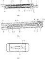
Fig. 1 is a structural diagram of a three-section synchronous slide rail according to a preferred embodiment of the present invention in a fully expanded state. -
Fig. 2 is a structural diagram of the present invention in a fully closed state. -
Fig. 3 is a partially enlarged structural view of a single-sided slide rail assembly in an expanded state. -
Fig. 4 is a single-sided slide rail assembly enlarged structural diagram in the closed state. -
Fig. 5 is a structural diagram of the connector. -
Fig. 6 is a structural diagram of a first side of the rope base. -
Fig. 7 is a structural diagram of a second side of the rope base. -
Fig. 8 is a diagram of the connection relationship between the protrusion and the flexible deflector. -
Fig. 9 is a cross-sectional view of the socket. -
Fig. 10 is a structural view of the end of the connecting rod. - The three-section synchronous slide rail shown in
Fig. 1 and Fig. 2 , a three-section synchronous slide rail, comprising: two sets ofslide rail assemblies 1a and 1b, wherein the two sets of theslide rail assemblies 1a and 1b are respectively installed with synchronization components, theslide rail assemblies 1a and 1b respectively comprise afixed rail 2, amiddle rail 3 and a slidingrail 4, the synchronization components respectively comprise aflexible deflector unit 6 and aroller 5 provided on the middle rail, wherein theflexible deflector unit 6 is respectively connected with thefixed rail 2 and the slidingrail 4, wherein themiddle rail 3 is further connected with arope base 7, therope base 7 is capable of rotating on themiddle rail 3, a first end of theflexible deflector unit 6 is wound around a first end of therope base 7 and then fixed to therope base 7, and a second end of theflexible deflector unit 6 bypasses theroller 5, then is reversely wound on a second end of therope base 7 and fixed to therope base 7, and aconnecting rod 8 is connected between therope bases 7 of the two sets of theslide rail assemblies 1a and 1b. - As shown in
Fig. 3, Fig. 4 , andFig. 8 , a first connector 9-1 is fixedly connected to the slidingrail 4, a second connector 9-2 is fixedly connected to thefixed rail 2, and the first connector 9-1 and the second connector 9-2 are respectively configured to connect the first flexible deflection member 6-1 and the second flexible deflection member 6-2 which are connected with therope base 7, and the third flexible deflection member 6-3 is in contact with theroller 5 and further connected with the first connector 9-1 and the second connector 9-2. Specifically, a first end of the first flexible deflecting piece 6-1 is fixed and wound on therope base 7, and a second end of the first flexible deflection piece 6-1 is connected to one end of the third flexible deflection member 6-3 via the first connector 9-1, and a second end of the third flexible deflection member 6-3 passes by theroller 5 to connect the second flexible deflection member 6-2 via the second connection member 9-2. A second end of the second flexible deflection member 6-2 is wound and fixedly connected to therope base 7. All ends of the first flexible deflection member 6-1, the second flexible deflection member 6-2, and the third flexible deflection member 6-3 are connected withfixing blocks 10 Of course, there may be one, two or even more than threeflexible deflection members 6, and they may not be connected by connecting members, as long as theflexible deflection member 6 can be fixed to the slidingrail 4 and thefixed rail 2 in other ways. - Further, as shown in
Figs. 5 ,6, and 7 , therope base 7 is cylindrical and therope base 7 is provided with aspiral groove 12, and theflexible deflection member 6 is wound around therope base 7 according to the rotation path of thespiral groove 12; wherein a length of theflexible deflection member 6 wounded on therope base 7 is greater than or equal to a length of theflexible deflection member 6 pulled out of therope base 7, that is, when theflexible deflection member 6 is fully pulled out, its pulled-out section can no longer be wound around therope base 7 and only connected to therope base 7, and there may also be a part of theflexible deflection member 6 wounded on therope base 7. Specifically, theoutlets spiral groove 12 are provided withfixed grooves 11,fixing grooves 11 are respectively provided on both middle portions of first connector 9-1 and the second connector 9-2; and two sides of thefixing grooves 11 of the first connector 9-1 and the second connector 9-2 extend to form grooves 11-1 matching with the size of theflexible deflection piece 6. A first end of the first flexible deflector 6-1 is installed in afirst fixing groove 12a on therope base 7 through afixing block 10; a second end of the first flexible deflector 6-1 and a first end of the third flexible deflector 6-3 are installed in thefixing groove 11 on the first connector 9-1 through a fixing block; and a second end of the third flexible deflector 6-3 and a first end of the second flexible deflector 6-2 are installed in thefixing groove 11 of the second connector 9-2 through fixing block and a second end of the second flexible deflector 6-2 is installed in asecond fixing groove 12b of therope base 7 through thefixing block 10. - The flexible deflector is specifically a rope. The
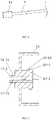
protrusion 10 is inserted into thefixing groove 11 by pulling theflexible deflection member 6. At this time, theflexible deflection member 6 shrinks, and theflexible deflection member 6 is always in a tensioned state by the pulling force of the rope. Not only is theflexible deflection element 6 easy to install, but theflexible deflection element 6 can be tensioned through a simple structure, and that in the actual installation process, a deviation of an actual distance and a theoretical distance between the twoslide rail assemblies 1a, 1b won't affect the tightness of theflexible deflector 6 and does not need to be adjusted. In addition, the connectingrod 8 is clamped with therope base 7. Specifically, as shown inFigs. 7 and10 , the connection 7-3 on therope base 7 protrudes and has connecting hole 7-4.The connecting hole 7-4 is flat and matches with the shape of the connecting end 8-1 of the connectingrod 8. The connecting end 8-1 of the connectingrod 8 extends into the connecting hole 7-4, so as to be clamped with therope base 7, so that the actual distance between the twoslide rail assemblies 1a, 1b can be adjusted to adjust the distance between the connecting end 8-1 of the connectingrod 8 inserting in a connection portion 7-3 of therope base 7 to make axial adjustment. At the same time,rope base 7 drives the connectingrod 8 to rotate in a circumferential direction can be ensured as well. - As shown in
Fig. 2 ,Fig. 4 ,Fig. 6 andFig. 9 , therope base 7 is covered with asocket 13, thesocket 13 wraps therope base 7, and thesocket 13 is provided with aflexible deflector inlet 14 to prevent the wear of foreign objects, it can play the role of guiding and protecting therope base 7 and theflexible deflection member 6. Specifically, the contact side of thesocket 13 and theintermediate rail 3 is provided with a first hook-shaped connecting member 13-1. The connector 13-1 is clamped with the hole on themiddle rail 3; the contact side of thesocket 13 and therope base 7 is provided with a connecting protrusion 13-2, and the connecting protrusion 13-2 is provided with a protrusion 13-3 which is configured to clamp with the second hook-shaped connector 7-1 in the groove on the side of therope base 7. - Further, the front end of the first hook-shaped connector 13-1 is provided with an inclined surface with a thin front and a thick rear surface, and the rear end of the inclined surface is provided with a first clamping groove 13-11, and through slots 13-12 are provided on a middle portion of the first hook-shaped connector 13-1, so that the first hook-shaped connector 13-1 can be easily inserted into the hole on the
middle rail 3, and when it needs to be disassembled, press the upper and lower ends of the first hook-shaped connector 13-1 , it can be separated from themiddle rail 3, which is easy to install and disassemble; the protrusion 13-3 is provided with a front thick and a rear thin slope, and the front end of the protrusion 13-3 is provided with a second clamping groove 13-21, the front end of the a second hook shaped connector 7-1 is provided with an inclined surface that matches with the protrusion 13-3, and the rear end of the inclined surface is a clamping groove, which is matched through the inclined surface of the second hook-shaped connector 7-1 and the inclined surface on the protrusion 13-3 during installation; the second hook-shaped connector 7-1 can be pressed into the second clamping groove 13-21 to complete the installation of thesocket 13 and therope base 7, which is very convenient. - In addition, a positioning rod 7-2 is provided in the middle of the
rope base 7 with a positioning block in the middle of thesocket 13, which is convenient for positioning during installation. - After adopting such a structure, when opened, most of the first flexible deflection member 6-1 wound on the
rope base 7 is pulled out by the pulling force of the first connecting member 9-1, and therope base 7 rotate to receive the second flexible deflector 6-2 into thespiral groove 12; when closed, the first connector 9-1 pulls the third flexible deflector 6-3, and the third flexible deflector 6-3 pulls the second connector 9-2 to pull out the second flexible deflector 6-2 which is mostly wounded on therope base 7, and therope base 7 rotates to receive the first flexible deflector 6-1 into thespiral groove 12 at the same time. The connectingrod 8 fixedly connected to therope base 7 keeps therope bases 7 on both sides rotating synchronously, and the sliding rail and the intermediate rail are kept in synchronous movement through the function of theflexible deflector 6 to realize thefixed rail 2, theintermediate rail 3 and the slidingrail 4 on the the two sets of slidingrail assemblies 1a and 1b all move synchronously; because only theflexible deflector 6, therope base 7 and the connectingrod 8 are needed to realize the synchronous movement of the two sets of slidingrails 1a and 1b, the structure is simple, and the installation, production, and replacement are convenient; and because theflexible deflection member 6 is wound and connected to therope base 7 and then connected to the two sets of slide rail assemblies through the connectingrod 8, theflexible deflection member 6 or the connectingrod 8 can be replaced separately during replacement, It is more convenient, and the connectingrod 8 is used as the component connecting the two sets ofslide rail assemblies 1a, 1b, which is less prone to wear and has a longer life. - One skilled in the art will understand that the embodiment of the present invention as shown in the drawings and described above is exemplary only and not intended to be limiting.
- It will thus be seen that the objects of the present invention have been fully and effectively accomplished. Its embodiments have been shown and described for the purposes of illustrating the functional and structural principles of the present invention and is subject to change without departure from such principles. Therefore, this invention includes all modifications encompassed within the scope of the following claims.
Claims (7)
- A three-section synchronous slide rail, comprising: two sets of slide rail (1a, 1b) assemblies, wherein the two sets of the slide rail (1a, 1b) assemblies are respectively installed with synchronization components, the slide rail (1a, 1b) assemblies respectively comprise a fixed rail (2), a middle rail (3) and a sliding rail (4), the synchronization components respectively comprise a flexible deflector unit (6) and a roller (5) provided on the middle rail (3), the flexible deflector unit (6) is respectively connected with the fixed rail (2) and the sliding rail (4), wherein the middle rail (3) is further connected with a rope base (7), the rope base (7) is capable of rotating on the middle rail (3), a first end of the flexible deflector unit (6) is wound around a first end of the rope base (7) and then fixed to the rope base. (7) and a second end of the flexible deflector unit (6) bypasses the roller (5), then is reversely wound on a second end of the rope base (7) and fixed to the rope base (7), and a connecting rod (8) is connected between the rope bases (7) of the two sets of the slide rail assemblies (1a, 1b).
- The three-section synchronous slide rail, as recited in claim 1, wherein a first connector is fixedly connected with the sliding rail, a second connector is fixedly connected with the fixed rail, and the first connector and the second connector are respectively configured to connect the flexible deflector unit.
- The three-section synchronous slide rail, as recited in claim 2, wherein a spiral groove is provided on the rope base, and the flexible deflector unit is wound on the rope base along a rotation path of the spiral groove.
- The three-section synchronous slide rail, as recited in claim 3, wherein the flexible deflector unit comprises a first flexible deflector, a second flexible deflector, and a third flexible deflector; wherein a first end of the first flexible deflector is fixed and wound on the rope base, and a second end of the first flexible deflector is connected to a first end of the third flexible deflector via the first connector, and a second end of the third flexible deflector is connected to a first end of the second flexible deflector through the second connector after bypassing the roller; a second end of the second flexible deflector is wound and connected on the rope base.
- The three-section synchronous slide rail, as recited in claim 4, wherein fixed grooves are provided on the openings of both ends of the spiral groove, fixed grooves are respectively provided on a middle portion of the first connector and the second connector, and the fixed grooves of the first connector and the second connector extend on both sides to form slots matching with a size of the flexible deflector unit; a first end of the first flexible deflector is installed in a first fixing groove on the rope base through a fixing block; a second end of the first flexible deflector and a first end of the third flexible deflector are installed in the fixing groove on the first connector through a fixing block; and a second end of the third flexible deflector and a first end of the second flexible deflector are installed in the fixing groove of the second connector through fixing block, and a second end of the second flexible deflector is installed in a second fixing groove of the rope base through the fixing block.
- The three-section synchronous slide rail, as recited in claim 1, wherein the rope base is sheathed with a socket, the socket wraps the rope base, an opening for the flexible deflector is provided on the socket; a first hook-shaped connector is provided on a side where the socket contacts the middle rail; the first hook-shaped connector is clamped with a hole on the middle rail; a connecting protrusion is provided on a side where socket contacts the rope base; wherein protrusions are provided on the connecting protrusion, which are used for clamping with the second hook-shape connector in the groove on a side of the rope base.
- The three-section synchronous slide rail, as recited in claim 6, wherein a front end of the first hook-shaped connector is provided with a thin front and a thick inclined surface, a rear end of the inclined surface is provided with a first clamping groove, and a through groove is opened in the middle of the first hook-shaped connector; thick and thin inclined surfaces are provided on the protrusion, the front end of the protrusion is provided with a second clamping groove, and the front end of the second hook-shaped connector is provided with an inclined surface for matching the protrusion.
Applications Claiming Priority (2)
| Application Number | Priority Date | Filing Date | Title |
|---|---|---|---|
| CN201810971292.1A CN108916226B (en) | 2018-08-24 | 2018-08-24 | Three-section synchronous slide rail |
| PCT/CN2019/101341 WO2020038324A1 (en) | 2018-08-24 | 2019-08-19 | Three-section synchronous slide rail |
Publications (3)
| Publication Number | Publication Date |
|---|---|
| EP3834664A1 EP3834664A1 (en) | 2021-06-16 |
| EP3834664A4 EP3834664A4 (en) | 2021-10-20 |
| EP3834664B1 true EP3834664B1 (en) | 2022-07-06 |
Family
ID=64406846
Family Applications (1)
| Application Number | Title | Priority Date | Filing Date |
|---|---|---|---|
| EP19853059.4A Active EP3834664B1 (en) | 2018-08-24 | 2019-08-19 | Three-section synchronous slide rail |
Country Status (5)
| Country | Link |
|---|---|
| US (1) | US11927216B2 (en) |
| EP (1) | EP3834664B1 (en) |
| CN (1) | CN108916226B (en) |
| MX (1) | MX2021002127A (en) |
| WO (1) | WO2020038324A1 (en) |
Families Citing this family (9)
| Publication number | Priority date | Publication date | Assignee | Title |
|---|---|---|---|---|
| CN108916226B (en) * | 2018-08-24 | 2023-08-18 | 无锡海达尔精密滑轨股份有限公司 | Three-section synchronous slide rail |
| CN109895069B (en) * | 2019-03-07 | 2024-11-26 | 江苏硕世生物科技股份有限公司 | Manipulator, transfer device, nucleic acid extraction and separation device, and sample plate transfer method |
| KR102226141B1 (en) * | 2019-03-12 | 2021-03-11 | (주)세고스 | Pull-out system |
| CN113494526A (en) * | 2020-04-07 | 2021-10-12 | 康普技术有限责任公司 | Guide rail system |
| EP3919770B1 (en) | 2020-06-05 | 2022-09-14 | Accuride International GmbH | Telescopic rail |
| CN112956846B (en) * | 2021-03-16 | 2024-08-06 | 合肥美的电冰箱有限公司 | Linear motion mechanism, drawer assembly and locker |
| CN114365913A (en) * | 2022-01-24 | 2022-04-19 | 江苏星徽精密科技有限公司 | Synchronous sliding rail driven by rope |
| CN114557557B (en) * | 2022-04-02 | 2023-07-28 | 四川大学华西第二医院 | A new type of case cabinet |
| CN121067002B (en) * | 2025-11-10 | 2026-03-27 | 江苏玖星精密科技股份有限公司 | Synchronous electric rail device |
Family Cites Families (17)
| Publication number | Priority date | Publication date | Assignee | Title |
|---|---|---|---|---|
| FR2608905B1 (en) * | 1986-12-30 | 1989-12-08 | Signaux Entr Electriques | TELESCOPIC BALL SLIDE ESPECIALLY FOR DRAWERS |
| US7686405B2 (en) * | 2005-04-20 | 2010-03-30 | True Manufacturing Co., Inc. | Self-closing sliding door assembly |
| AT506441A1 (en) * | 2008-03-07 | 2009-09-15 | Blum Gmbh Julius | MICRICULAR DRIVE WITH A DRIVE UNIT |
| DE112009001940B4 (en) * | 2008-08-07 | 2020-12-31 | Accuride International Inc. | Synchronization / stabilization system and self-moving mechanism for drawer applications |
| DE202008012100U1 (en) * | 2008-09-12 | 2010-02-11 | Paul Hettich Gmbh & Co. Kg | Synchronous guide of a push element |
| CN202229523U (en) * | 2011-08-05 | 2012-05-23 | 合肥美的荣事达电冰箱有限公司 | Slide rail assembly for refrigerator drawer and refrigerator with slide rail assembly |
| DE102012006832A1 (en) * | 2012-04-03 | 2013-10-10 | Faurecia Innenraum Systeme Gmbh | DRAWER FOR A DRAWER, DRAWER WITH AN EXTRACT AND VEHICLE WITH A DRAWER |
| DE102013113672A1 (en) * | 2013-06-14 | 2014-12-18 | Paul Hettich Gmbh & Co. Kg | pull-out system |
| DE102014107692A1 (en) * | 2014-06-02 | 2015-12-03 | Paul Hettich Gmbh & Co. Kg | pusher assembly |
| DE102014119729B4 (en) * | 2014-12-30 | 2024-04-11 | Paul Hettich Gmbh & Co. Kg | Linear guide for moving parts of furniture, household appliances or the like |
| CN106419210A (en) * | 2016-09-26 | 2017-02-22 | 无锡晶美精密滑轨有限公司 | Synchronous hidden sliding rail |
| CN106724189B (en) * | 2017-01-23 | 2022-06-10 | 无锡海达尔精密滑轨股份有限公司 | Three-section type synchronous drawer slide rail |
| CN108158249A (en) * | 2017-11-22 | 2018-06-15 | 北京理工华汇智能科技有限公司 | Automatic drawing and its control method |
| CN107811440A (en) * | 2017-11-24 | 2018-03-20 | 无锡晶美精密滑轨有限公司 | The anti-skidding gear mechanism of slide rail timing belt |
| CN208870928U (en) * | 2018-08-24 | 2019-05-17 | 无锡海达尔精密滑轨股份有限公司 | A kind of three-section type synchronous sliding track |
| CN108916226B (en) * | 2018-08-24 | 2023-08-18 | 无锡海达尔精密滑轨股份有限公司 | Three-section synchronous slide rail |
| KR102226141B1 (en) * | 2019-03-12 | 2021-03-11 | (주)세고스 | Pull-out system |
-
2018
- 2018-08-24 CN CN201810971292.1A patent/CN108916226B/en active Active
-
2019
- 2019-08-19 WO PCT/CN2019/101341 patent/WO2020038324A1/en not_active Ceased
- 2019-08-19 US US17/270,859 patent/US11927216B2/en active Active
- 2019-08-19 EP EP19853059.4A patent/EP3834664B1/en active Active
- 2019-08-19 MX MX2021002127A patent/MX2021002127A/en unknown
Also Published As
| Publication number | Publication date |
|---|---|
| EP3834664A4 (en) | 2021-10-20 |
| WO2020038324A1 (en) | 2020-02-27 |
| US11927216B2 (en) | 2024-03-12 |
| EP3834664A1 (en) | 2021-06-16 |
| US20210199155A1 (en) | 2021-07-01 |
| CN108916226B (en) | 2023-08-18 |
| CN108916226A (en) | 2018-11-30 |
| MX2021002127A (en) | 2021-07-16 |
Similar Documents
| Publication | Publication Date | Title |
|---|---|---|
| EP3834664A1 (en) | Three-section synchronous slide rail | |
| EP2564729B1 (en) | Household appliance | |
| EP3217090B1 (en) | Improved adapter for supporting and electrically connecting a lighting apparatus to an electrified track and lighting unit using the same | |
| JP7003069B2 (en) | How to install drawer elements and configuration kits, furniture and indoor fixtures for displacementably mounting drawer elements | |
| EP3176016B1 (en) | Rollo assembly | |
| CN115327199A (en) | Anti-theft electric energy meter | |
| US20090253289A1 (en) | Termination device impedance assembly | |
| CN118174208A (en) | A cable limit device for electromechanical installation for maintenance | |
| CN114759750A (en) | Forming equipment and method for flat wire stator winding | |
| TWI867104B (en) | A device and system for moving a door leaf between an open position and a close position with regard to a door opening in a wall and a method for mounting the device | |
| CN119009845B (en) | Intelligent bus duct with smooth and uniform butt joint and butt joint method thereof | |
| CN115954221B (en) | A retractable, low-wear dynamic connector | |
| CN115966417B (en) | Low-abrasion movable connector with guiding function | |
| CN210640492U (en) | Cable terminal fixing device | |
| US20250141126A1 (en) | Conductor terminal | |
| CN118508110A (en) | Wiring terminal | |
| CN216529609U (en) | Low-abrasion movable connector contact system adjusting mechanism | |
| KR101704585B1 (en) | 3 Sliding System Door | |
| CN117219379A (en) | A power insulator string hanging device with adjustable spacing | |
| CN218548352U (en) | Static contact for circuit breaker | |
| CN222146918U (en) | Switch assembly and disassembly parts of power distribution cabinet | |
| CN218919439U (en) | U-LOCK anti-loosening plug | |
| CN120784696B (en) | Assembly line overhead structure for automobile wire harness production | |
| CN222355671U (en) | A conductive ring with palladium-gold composite coating | |
| CN119651479B (en) | Cable branch structure of low-voltage complete equipment |
Legal Events
| Date | Code | Title | Description |
|---|---|---|---|
| STAA | Information on the status of an ep patent application or granted ep patent |
Free format text: STATUS: THE INTERNATIONAL PUBLICATION HAS BEEN MADE |
|
| PUAI | Public reference made under article 153(3) epc to a published international application that has entered the european phase |
Free format text: ORIGINAL CODE: 0009012 |
|
| STAA | Information on the status of an ep patent application or granted ep patent |
Free format text: STATUS: REQUEST FOR EXAMINATION WAS MADE |
|
| 17P | Request for examination filed |
Effective date: 20210312 |
|
| AK | Designated contracting states |
Kind code of ref document: A1 Designated state(s): AL AT BE BG CH CY CZ DE DK EE ES FI FR GB GR HR HU IE IS IT LI LT LU LV MC MK MT NL NO PL PT RO RS SE SI SK SM TR |
|
| A4 | Supplementary search report drawn up and despatched |
Effective date: 20210921 |
|
| RIC1 | Information provided on ipc code assigned before grant |
Ipc: A47B 88/49 20170101ALI20210915BHEP Ipc: A47B 88/447 20170101ALI20210915BHEP Ipc: A47B 88/40 20170101AFI20210915BHEP |
|
| DAV | Request for validation of the european patent (deleted) | ||
| DAX | Request for extension of the european patent (deleted) | ||
| GRAP | Despatch of communication of intention to grant a patent |
Free format text: ORIGINAL CODE: EPIDOSNIGR1 |
|
| STAA | Information on the status of an ep patent application or granted ep patent |
Free format text: STATUS: GRANT OF PATENT IS INTENDED |
|
| INTG | Intention to grant announced |
Effective date: 20220215 |
|
| GRAS | Grant fee paid |
Free format text: ORIGINAL CODE: EPIDOSNIGR3 |
|
| GRAA | (expected) grant |
Free format text: ORIGINAL CODE: 0009210 |
|
| STAA | Information on the status of an ep patent application or granted ep patent |
Free format text: STATUS: THE PATENT HAS BEEN GRANTED |
|
| AK | Designated contracting states |
Kind code of ref document: B1 Designated state(s): AL AT BE BG CH CY CZ DE DK EE ES FI FR GB GR HR HU IE IS IT LI LT LU LV MC MK MT NL NO PL PT RO RS SE SI SK SM TR |
|
| REG | Reference to a national code |
Ref country code: AT Ref legal event code: REF Ref document number: 1502224 Country of ref document: AT Kind code of ref document: T Effective date: 20220715 Ref country code: CH Ref legal event code: EP |
|
| REG | Reference to a national code |
Ref country code: DE Ref legal event code: R096 Ref document number: 602019016835 Country of ref document: DE |
|
| REG | Reference to a national code |
Ref country code: IE Ref legal event code: FG4D |
|
| REG | Reference to a national code |
Ref country code: LT Ref legal event code: MG9D |
|
| REG | Reference to a national code |
Ref country code: NL Ref legal event code: MP Effective date: 20220706 |
|
| PG25 | Lapsed in a contracting state [announced via postgrant information from national office to epo] |
Ref country code: SE Free format text: LAPSE BECAUSE OF FAILURE TO SUBMIT A TRANSLATION OF THE DESCRIPTION OR TO PAY THE FEE WITHIN THE PRESCRIBED TIME-LIMIT Effective date: 20220706 Ref country code: RS Free format text: LAPSE BECAUSE OF FAILURE TO SUBMIT A TRANSLATION OF THE DESCRIPTION OR TO PAY THE FEE WITHIN THE PRESCRIBED TIME-LIMIT Effective date: 20220706 Ref country code: PT Free format text: LAPSE BECAUSE OF FAILURE TO SUBMIT A TRANSLATION OF THE DESCRIPTION OR TO PAY THE FEE WITHIN THE PRESCRIBED TIME-LIMIT Effective date: 20221107 Ref country code: NO Free format text: LAPSE BECAUSE OF FAILURE TO SUBMIT A TRANSLATION OF THE DESCRIPTION OR TO PAY THE FEE WITHIN THE PRESCRIBED TIME-LIMIT Effective date: 20221006 Ref country code: NL Free format text: LAPSE BECAUSE OF FAILURE TO SUBMIT A TRANSLATION OF THE DESCRIPTION OR TO PAY THE FEE WITHIN THE PRESCRIBED TIME-LIMIT Effective date: 20220706 Ref country code: LV Free format text: LAPSE BECAUSE OF FAILURE TO SUBMIT A TRANSLATION OF THE DESCRIPTION OR TO PAY THE FEE WITHIN THE PRESCRIBED TIME-LIMIT Effective date: 20220706 Ref country code: LT Free format text: LAPSE BECAUSE OF FAILURE TO SUBMIT A TRANSLATION OF THE DESCRIPTION OR TO PAY THE FEE WITHIN THE PRESCRIBED TIME-LIMIT Effective date: 20220706 Ref country code: FI Free format text: LAPSE BECAUSE OF FAILURE TO SUBMIT A TRANSLATION OF THE DESCRIPTION OR TO PAY THE FEE WITHIN THE PRESCRIBED TIME-LIMIT Effective date: 20220706 Ref country code: ES Free format text: LAPSE BECAUSE OF FAILURE TO SUBMIT A TRANSLATION OF THE DESCRIPTION OR TO PAY THE FEE WITHIN THE PRESCRIBED TIME-LIMIT Effective date: 20220706 |
|
| REG | Reference to a national code |
Ref country code: AT Ref legal event code: MK05 Ref document number: 1502224 Country of ref document: AT Kind code of ref document: T Effective date: 20220706 |
|
| PG25 | Lapsed in a contracting state [announced via postgrant information from national office to epo] |
Ref country code: PL Free format text: LAPSE BECAUSE OF FAILURE TO SUBMIT A TRANSLATION OF THE DESCRIPTION OR TO PAY THE FEE WITHIN THE PRESCRIBED TIME-LIMIT Effective date: 20220706 Ref country code: IS Free format text: LAPSE BECAUSE OF FAILURE TO SUBMIT A TRANSLATION OF THE DESCRIPTION OR TO PAY THE FEE WITHIN THE PRESCRIBED TIME-LIMIT Effective date: 20221106 Ref country code: HR Free format text: LAPSE BECAUSE OF FAILURE TO SUBMIT A TRANSLATION OF THE DESCRIPTION OR TO PAY THE FEE WITHIN THE PRESCRIBED TIME-LIMIT Effective date: 20220706 Ref country code: GR Free format text: LAPSE BECAUSE OF FAILURE TO SUBMIT A TRANSLATION OF THE DESCRIPTION OR TO PAY THE FEE WITHIN THE PRESCRIBED TIME-LIMIT Effective date: 20221007 |
|
| REG | Reference to a national code |
Ref country code: CH Ref legal event code: PL |
|
| REG | Reference to a national code |
Ref country code: DE Ref legal event code: R097 Ref document number: 602019016835 Country of ref document: DE |
|
| PG25 | Lapsed in a contracting state [announced via postgrant information from national office to epo] |
Ref country code: SM Free format text: LAPSE BECAUSE OF FAILURE TO SUBMIT A TRANSLATION OF THE DESCRIPTION OR TO PAY THE FEE WITHIN THE PRESCRIBED TIME-LIMIT Effective date: 20220706 Ref country code: RO Free format text: LAPSE BECAUSE OF FAILURE TO SUBMIT A TRANSLATION OF THE DESCRIPTION OR TO PAY THE FEE WITHIN THE PRESCRIBED TIME-LIMIT Effective date: 20220706 Ref country code: MC Free format text: LAPSE BECAUSE OF FAILURE TO SUBMIT A TRANSLATION OF THE DESCRIPTION OR TO PAY THE FEE WITHIN THE PRESCRIBED TIME-LIMIT Effective date: 20220706 Ref country code: LU Free format text: LAPSE BECAUSE OF NON-PAYMENT OF DUE FEES Effective date: 20220819 Ref country code: LI Free format text: LAPSE BECAUSE OF NON-PAYMENT OF DUE FEES Effective date: 20220831 Ref country code: DK Free format text: LAPSE BECAUSE OF FAILURE TO SUBMIT A TRANSLATION OF THE DESCRIPTION OR TO PAY THE FEE WITHIN THE PRESCRIBED TIME-LIMIT Effective date: 20220706 Ref country code: CZ Free format text: LAPSE BECAUSE OF FAILURE TO SUBMIT A TRANSLATION OF THE DESCRIPTION OR TO PAY THE FEE WITHIN THE PRESCRIBED TIME-LIMIT Effective date: 20220706 Ref country code: CH Free format text: LAPSE BECAUSE OF NON-PAYMENT OF DUE FEES Effective date: 20220831 Ref country code: AT Free format text: LAPSE BECAUSE OF FAILURE TO SUBMIT A TRANSLATION OF THE DESCRIPTION OR TO PAY THE FEE WITHIN THE PRESCRIBED TIME-LIMIT Effective date: 20220706 |
|
| REG | Reference to a national code |
Ref country code: BE Ref legal event code: MM Effective date: 20220831 |
|
| PLBE | No opposition filed within time limit |
Free format text: ORIGINAL CODE: 0009261 |
|
| STAA | Information on the status of an ep patent application or granted ep patent |
Free format text: STATUS: NO OPPOSITION FILED WITHIN TIME LIMIT |
|
| PG25 | Lapsed in a contracting state [announced via postgrant information from national office to epo] |
Ref country code: SK Free format text: LAPSE BECAUSE OF FAILURE TO SUBMIT A TRANSLATION OF THE DESCRIPTION OR TO PAY THE FEE WITHIN THE PRESCRIBED TIME-LIMIT Effective date: 20220706 Ref country code: EE Free format text: LAPSE BECAUSE OF FAILURE TO SUBMIT A TRANSLATION OF THE DESCRIPTION OR TO PAY THE FEE WITHIN THE PRESCRIBED TIME-LIMIT Effective date: 20220706 |
|
| 26N | No opposition filed |
Effective date: 20230411 |
|
| PG25 | Lapsed in a contracting state [announced via postgrant information from national office to epo] |
Ref country code: AL Free format text: LAPSE BECAUSE OF FAILURE TO SUBMIT A TRANSLATION OF THE DESCRIPTION OR TO PAY THE FEE WITHIN THE PRESCRIBED TIME-LIMIT Effective date: 20220706 |
|
| PG25 | Lapsed in a contracting state [announced via postgrant information from national office to epo] |
Ref country code: IE Free format text: LAPSE BECAUSE OF NON-PAYMENT OF DUE FEES Effective date: 20220819 Ref country code: FR Free format text: LAPSE BECAUSE OF NON-PAYMENT OF DUE FEES Effective date: 20220906 |
|
| PG25 | Lapsed in a contracting state [announced via postgrant information from national office to epo] |
Ref country code: SI Free format text: LAPSE BECAUSE OF FAILURE TO SUBMIT A TRANSLATION OF THE DESCRIPTION OR TO PAY THE FEE WITHIN THE PRESCRIBED TIME-LIMIT Effective date: 20220706 |
|
| PG25 | Lapsed in a contracting state [announced via postgrant information from national office to epo] |
Ref country code: BE Free format text: LAPSE BECAUSE OF NON-PAYMENT OF DUE FEES Effective date: 20220831 |
|
| PG25 | Lapsed in a contracting state [announced via postgrant information from national office to epo] |
Ref country code: IT Free format text: LAPSE BECAUSE OF FAILURE TO SUBMIT A TRANSLATION OF THE DESCRIPTION OR TO PAY THE FEE WITHIN THE PRESCRIBED TIME-LIMIT Effective date: 20220706 |
|
| GBPC | Gb: european patent ceased through non-payment of renewal fee |
Effective date: 20230819 |
|
| PG25 | Lapsed in a contracting state [announced via postgrant information from national office to epo] |
Ref country code: CY Free format text: LAPSE BECAUSE OF FAILURE TO SUBMIT A TRANSLATION OF THE DESCRIPTION OR TO PAY THE FEE WITHIN THE PRESCRIBED TIME-LIMIT Effective date: 20220706 |
|
| PG25 | Lapsed in a contracting state [announced via postgrant information from national office to epo] |
Ref country code: MK Free format text: LAPSE BECAUSE OF FAILURE TO SUBMIT A TRANSLATION OF THE DESCRIPTION OR TO PAY THE FEE WITHIN THE PRESCRIBED TIME-LIMIT Effective date: 20220706 Ref country code: HU Free format text: LAPSE BECAUSE OF FAILURE TO SUBMIT A TRANSLATION OF THE DESCRIPTION OR TO PAY THE FEE WITHIN THE PRESCRIBED TIME-LIMIT; INVALID AB INITIO Effective date: 20190819 |
|
| PG25 | Lapsed in a contracting state [announced via postgrant information from national office to epo] |
Ref country code: GB Free format text: LAPSE BECAUSE OF NON-PAYMENT OF DUE FEES Effective date: 20230819 |
|
| PG25 | Lapsed in a contracting state [announced via postgrant information from national office to epo] |
Ref country code: GB Free format text: LAPSE BECAUSE OF NON-PAYMENT OF DUE FEES Effective date: 20230819 Ref country code: BG Free format text: LAPSE BECAUSE OF FAILURE TO SUBMIT A TRANSLATION OF THE DESCRIPTION OR TO PAY THE FEE WITHIN THE PRESCRIBED TIME-LIMIT Effective date: 20220706 |
|
| PG25 | Lapsed in a contracting state [announced via postgrant information from national office to epo] |
Ref country code: MT Free format text: LAPSE BECAUSE OF FAILURE TO SUBMIT A TRANSLATION OF THE DESCRIPTION OR TO PAY THE FEE WITHIN THE PRESCRIBED TIME-LIMIT Effective date: 20220706 |
|
| PGFP | Annual fee paid to national office [announced via postgrant information from national office to epo] |
Ref country code: DE Payment date: 20250812 Year of fee payment: 7 |
|
| PGFP | Annual fee paid to national office [announced via postgrant information from national office to epo] |
Ref country code: TR Payment date: 20250808 Year of fee payment: 7 |