EP3834649A1 - Element and slide fastener - Google Patents
Element and slide fastener Download PDFInfo
- Publication number
- EP3834649A1 EP3834649A1 EP18929776.5A EP18929776A EP3834649A1 EP 3834649 A1 EP3834649 A1 EP 3834649A1 EP 18929776 A EP18929776 A EP 18929776A EP 3834649 A1 EP3834649 A1 EP 3834649A1
- Authority
- EP
- European Patent Office
- Prior art keywords
- concave portion
- engaging concave
- engaging
- elements
- measured
- Prior art date
- Legal status (The legal status is an assumption and is not a legal conclusion. Google has not performed a legal analysis and makes no representation as to the accuracy of the status listed.)
- Granted
Links
Images





Classifications
-
- A—HUMAN NECESSITIES
- A44—HABERDASHERY; JEWELLERY
- A44B—BUTTONS, PINS, BUCKLES, SLIDE FASTENERS, OR THE LIKE
- A44B19/00—Slide fasteners
- A44B19/02—Slide fasteners with a series of separate interlocking members secured to each stringer tape
- A44B19/04—Stringers arranged edge-to-edge when fastened, e.g. abutting stringers
- A44B19/06—Stringers arranged edge-to-edge when fastened, e.g. abutting stringers with substantially rectangular members having interlocking projections and pieces
-
- A—HUMAN NECESSITIES
- A44—HABERDASHERY; JEWELLERY
- A44B—BUTTONS, PINS, BUCKLES, SLIDE FASTENERS, OR THE LIKE
- A44B19/00—Slide fasteners
- A44B19/24—Details
- A44B19/40—Connection of separate, or one-piece, interlocking members to stringer tapes; Reinforcing such connections, e.g. by stitching
- A44B19/403—Connection of separate interlocking members
Definitions
- the present invention relates to a metal element, which is configured to be engaged with or disengaged from another element by moving a slider, and to a slide fastener.
- an element in which a rib is provided on an inner surface of a front end wall of an engaging concave portion formed in an engaging head thereof in order to obtain a strong engagement strength capable of withstanding an external force, such as a crosswise force or a puncturing force (Patent Literature 1).
- Patent Literature 1 Japanese Utility Model Publication No. H1-22505
- Patent Literature 1 since the element described in Patent Literature 1 is provided with the rib on the inner surface of the front end wall of the engaging concave portion, there is a possibility that when, as shown in Fig. 7 of Patent Literature 1, an engaging convex portion of an element on one side climbs over a front end wall of an engaging concave portion of an element on the other side and then engages with the engaging concave portion, the engaging convex portion of the element on the one side interferes with a rib provided on the front end wall of the engaging concave portion of the element on the other side, thereby making a sliding property poor.
- An object of the present invention is to provide an element and a slide fastener, which have an improved puncture strength while maintaining a sliding property when engaging elements with each other.
- a maximum width Wp of the protrusion as measured on a surface and a maximum width Wbox of the engaging concave portion as measured on the surface satisfy a following equation (1): 20 % ⁇ Wp / Wbox ⁇ 55 % wherein the surface refers to a surface of the element, on which the fitting concave portion is formed.
- a maximum height Hp of the protrusion as measured from a surface and a maximum height Hbox of the engaging concave portion as measured from the surface satisfy a following equation (2): 5 % ⁇ Hp / Hbox ⁇ 15 % wherein the surface refers to a surface of the element, on which the engaging concave portion is formed.
- an allowable relative rotation angle ⁇ between the engaging convex portion and the engaging concave portion in an engaged state satisfies a following equation (3): ⁇ 20 ° ⁇ ⁇ ⁇ 20 ° wherein ⁇ is 0° when distal ends of the heads of two engaged elements are parallel with each other.
- Fig. 1 shows a slide fastener 1 in which an element 10 of the present embodiment is attached. Meanwhile, in the following embodiments, as shown in Fig. 1 , an arrow F represents a forward direction, an arrow B represents a rearward direction, an arrow L represents a left direction, and an arrow R represents a right direction.
- the slide fastener 1 illustrated in the present embodiment includes a pair of left and right fastener chains 2 including a first fastener stringer 3L, which has a plurality of first elements 10L fixed on an edge portion 5L of a first fastener tape 4L thereof, and a second fastener stringer 3R, which has a plurality of second elements 10R fixed on an edge portion 5R of a second fastener tape 4R thereof; and a first slider 7 and a second slider 8 configured to slide along the left and right elements 10L, 10R and thus to engage or disengage the left and right elements 10L, 10R with or from each other.
- the fastener chain 2 consists of a pair of fastener stringers 3L, 3R.
- the fastener stringers 3L, 3R have a pair of fastener tapes 4L, 4R and a plurality of elements 10L, 10R fixed on the respective edge portions 5L, 5R of a pair of fastener tapes 4L, 4R at a predetermined pitch.
- the elements 10L, 10R are arranged to oppose each other.
- the fastener chain 2 of the present embodiment is configured as a two-side-opening type, in which the fastener chain 2 can be opened or closed in the forward and rearward direction.
- the fastener chain 2 is not limited to the two-side opening type, but may be a one-side-opening type.
- the elements 10L, 10R of the left and right fastener chains 2 are engaged with each other by moving the first slider 7 in the forward direction as shown by the arrow F, whereas the elements 10L, 10R are disengaged from each other by moving the first slider 7 in the rearward direction as shown by the arrow B. Also, the elements 10L, 10R of the left and right fastener chains 2 are engaged with each other by moving the second slider 8 in the rearward direction as shown by the arrow B, whereas the elements 10L, 10R are disengaged from each other by moving the second slider 8 in the forward direction as shown by the arrow F.
- the forward and rearward direction is a moving direction of the slider 7 and is also a tape length direction of the fastener tapes 4L, 4R.
- the left and right direction (L-R direction) as shown by the arrows L, R is a width direction of the fastener tapes 4L, 4R and is also a direction perpendicular to the forward and rearward direction.
- the left and right direction (L-R direction) is also a direction of a rotation axis of a pull 71 of the slider 7.
- an upward and downward direction (U-D direction) not shown in the drawings, which is perpendicular to the paper surface, is a direction perpendicular to tape surfaces of the fastener tapes 4L, 4R.
- Fig. 2 shows a perspective view of the element 10 according to the first embodiment.
- Fig. 3 shows an A-A sectional view of the element 10 according to the first embodiment.
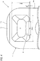
- Fig. 4 shows a view of the element 10 according to the first embodiment, as viewed from the side of an engaging concave portion 14.
- the element 10 is a metal product manufactured by press working or the like and is used in the slide fastener 1 as shown in Fig. 1 .
- the element 10 includes a head 11 configured to be engaged with another element 10 opposing thereto when the slide fastener 1 has been closed, and leg portions 12 attached to the respective edge portions 5L, 5R of the fastener tapes 4L, 4R.
- the head 11 is provided with an engaging convex portion 13 protruding from one surface thereof and an engaging concave portion 14 formed on the other surface.
- an inclined portion 15 is formed to facilitate engagement with another element 10 opposing thereto when the fastener is engaged from the side of the engaging concave portion 14.
- the inclined portion 15 is formed such that the distal end of the head 11 on the side of the engaging concave portion 14 is chamfered.
- the engaging convex portion 13 is formed to be tapered such that a circumferential length thereof becomes shorter as it further protrudes.
- the engaging concave portion 14 is formed such that the back side of the engaging convex portion 13 is hollowed. Also, the engaging concave portion 14 is formed to be tapered such that a circumferential length thereof becomes shorter as it goes inward.
- a protrusion 16 is formed on a side of the engaging concave portion 14 close to the leg portions 12. The protrusion 16 is formed to be inclined inward of the fitting concave portion 14 to correspond to the fitting concave portion 14 which is formed to be tapered.
- a maximum width Wp of the protrusion 16 as measured on the surface 10a and a maximum width Wbox of the engaging concave portion 14 as measured on the surface 10a satisfy a following equation (1).
- the surface 10a refers to a surface of the element 10, on which the fitting concave portion 14 is formed. 20 % ⁇ Wp / Wbox ⁇ 55 %
- Wp is the maximum width of the protrusion 16 as measured on the surface 10a
- Wbox is the maximum width of the engaging concave portion 14 as measured on the surface 10a.
- a maximum height Hp of the protrusion 16 as measured from the surface 10a and a maximum height Hbox of the engaging concave portion 14 as measured from the surface 10a satisfy a following equation (2).
- the surface 10a refers to a surface of the element 10, on which the fitting concave portion 14 is formed. 5 % ⁇ Hp / Hbox ⁇ 15 %
- Hp is the maximum height of the protrusion 16 as measured from the surface 10a of the engaging concave portion 14 close to the leg portions 12; and Hbox is the maximum height of the engaging concave portion 14 as measured from the surface 10a of the engaging concave portion 14 close to the leg portions 12.
- the leg portions 12 includes two leg portions 12 extending from the head 11 such that an attachment portion 17, into which the edge portion 5 of the fastener tape 4 is to be fitted, is interposed therebetween.
- the element 10 is configured to be attached to the fastener tape 4 by fitting the edge portion 5 of the fastener tape 4 into the attachment portion 17 and crimping the two leg portions 12.
- Fig. 5 shows an element row 10' according to the first embodiment.
- the element 10 is attached to the edge portion 5 of the fastener tape 4 by crimping the leg portions 12.
- the element row 10' is preferably formed by arranging a plurality of elements 10 in the same orientation at equal intervals.
- the interval between the elements 10 is preferably equal to or larger than a thickness of the leg portions 12 of the elements 10.
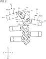
- Fig. 6 shows engagement of the elements 10 according to the first embodiment. However, in Fig. 6 , the fastener tapes 4 and the edge portions 5 thereof are omitted.
- the element rows 10L', 10R' according to the present embodiment are engaged with each other by moving the slider 7 (see Fig. 1 ) in the forward direction F and disengaged from each other by moving the slider 7 in the rearward direction B.
- the element rows 10L', 10R' of the present embodiment when a left element 10L is engaged with a right element 10R, the left element 10L and the right element 10R come close to each other and then the engaging convex portion 13L of the left element 10L comes into contact with the inclined portion 15R of the right element 10R.
- the engaging convex portion 13L of the left element 10L is guided by the inclined portion 15R of the right element 10R to be led into the engaging concave portion 14R of the right element 10R.
- the engaging convex portion 13L of the left element 10L is inserted into the engaging concave portion 14R of the right element 10R.
- the engaging convex portion 13L of the left element 10L enters the engaging concave portion 14R of the right element 10R along a surface thereof opposite to the protrusion 16R.
- the left element 10L and the right element 10R are engaged with each other.
- a right element 10R is engaged with a left element 10L, it may be deemed such that the left and right sides are in reverse. This operation is repeated for the left elements 10L and the right elements 10R, thereby achieving engagement of the element rows 10L', 10R'.
- the protrusion 16R does not interfere with the engaging convex portion 13L, thereby the slider 7 can smoothly slide and also the element rows 10L', 10R' can be accurately engaged with each other.
- Fig. 7 shows the engaging convex portion 13 and the engaging concave portion 14 rotated relative to each other while the elements 10 according to the first embodiment are engaged with each other.
- Fig. 8 shows an enlarged sectional view of the engaging convex portion and the engaging concave portion shown in Fig. 7 .
- the left element 10L and the right element 10R according to the present embodiment are formed to be rotatable relative to each other by a predetermined angle in an engaged state. As shown in Fig. 7 , an allowable relative rotation angle ⁇ satisfies a following equation (3). ⁇ 30 ° ⁇ ⁇ ⁇ 30 °
- ⁇ is 0° when the distal ends 11a of the heads of the two engaged elements 10 are parallel with each other.
- the slide fastener 1 in which these elements 10 are attached can be easily deformed and thus can be used for many types of products.
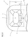
- Fig. 9 shows a view of the element 10 according to a second embodiment, as viewed from the side of an engaging concave portion 14.
- a width Wp of the protrusions 16 is a distance from the left side of the left protrusion 16 on the surface 10a to the right side of the right protrusion 16 on the surface 10a.
- a maximum width Wp of the protrusions 16 as measured on the surface 10a and a maximum width Wbox of the engaging concave portion 14 as measured on the surface 10a satisfy the above equation (1).
- a maximum height Hp of the protrusions 16 as measured from the surface 10a and a maximum height Hbox of the engaging concave portion 14 as measured from the surface 10a satisfy the above equation (2).
- a width Wp of the protrusions 16 is a distance from the left side of the most left protrusion 16 on the surface 10a to the right side of the most right protrusion 16 on the surface 10a.
- a height Hp of the protrusions 16 is a height of the protrusions 16 at both ends as measured from the surface 10a.
- the element 10 according to the present embodiment may be provided with a protruding portion on a side of the engaging concave portion 14 close to the distal end 11a, in addition to the side of the engaging concave portion 14 close to the leg portions 12.
- the element 10 includes the head 11 having the engaging convex portion 13 protruding from one surface thereof and the engaging concave portion 14 formed on the back side of the engaging convex portion 13 on the other surface; and the pair of leg portions 12 extending from the head 11, wherein the protrusion 16 is formed on the side of the engaging concave portion 14 close to the leg portions 12 to protrude inward of the engaging concave portion 14. Therefore, it is possible to improve the puncture strength while maintaining the sliding property when engaging the elements 10 with each other.
- a maximum width Wp of the protrusion 16 as measured on the surface 10a and a maximum width Wbox of the engaging concave portion 14 as measured on the surface 10a satisfy the following equation (1). 20 % ⁇ Wp / Wbox ⁇ 55 %
- the surface 10a refers to a surface of the element 10, on which the fitting concave portion 14 is formed.
- a maximum height Hp of the protrusion 16 as measured from the surface 10a and a maximum height Hbox of the engaging concave portion 14 as measured from the surface 10a satisfy the following equation (2). 5 % ⁇ Hp / Hbox ⁇ 15 %
- the surface 10a refers to a surface of the element 10, on which the engaging concave portion 14 is formed.
- an allowable relative rotation angle ⁇ between the engaging convex portion 13 and the engaging concave portion 14 in the engaged state satisfies the following equation (3). ⁇ 20 ° ⁇ ⁇ ⁇ 20 °
- ⁇ is 0° when the distal ends 11a of the heads of the two engaged elements 10 are parallel with each other.
- the slide fastener 1 employing the element 10 can be easily deformed and thus can be used for many types of products.
- the slide fastener 1 includes the pair of fastener tapes 2; the plurality of the above-described elements 10 each fixed on the pair of fastener tapes 2; and the slider 7 configured to engage or disengage the elements 10 with or from each other when the elements 10 pass therethrough. Therefore, according to the slide fastener 1, it is possible to improve the puncture strength while maintaining the sliding property when engaging the elements 10 with each other.
Landscapes
- Slide Fasteners (AREA)
Abstract
Description
- The present invention relates to a metal element, which is configured to be engaged with or disengaged from another element by moving a slider, and to a slide fastener.
- Conventionally, an element is disclosed, in which a rib is provided on an inner surface of a front end wall of an engaging concave portion formed in an engaging head thereof in order to obtain a strong engagement strength capable of withstanding an external force, such as a crosswise force or a puncturing force (Patent Literature 1).
- Patent Literature 1: Japanese Utility Model Publication No.
H1-22505 - However, since the element described in Patent Literature 1 is provided with the rib on the inner surface of the front end wall of the engaging concave portion, there is a possibility that when, as shown in
Fig. 7 of Patent Literature 1, an engaging convex portion of an element on one side climbs over a front end wall of an engaging concave portion of an element on the other side and then engages with the engaging concave portion, the engaging convex portion of the element on the one side interferes with a rib provided on the front end wall of the engaging concave portion of the element on the other side, thereby making a sliding property poor. - An object of the present invention is to provide an element and a slide fastener, which have an improved puncture strength while maintaining a sliding property when engaging elements with each other.
- An element according to one embodiment of the present invention includes:
- a head having an engaging convex portion protruding from one surface thereof and an engaging concave portion formed on a back side of the engaging convex portion on the other surface; and
- a pair of leg portions extending from the head,
- wherein a protrusion is formed on a side of the engaging concave portion close to the leg portions to protrude inward of the engaging concave portion.
- In the element according to one embodiment of the present invention,
a maximum width Wp of the protrusion as measured on a surface and a maximum width Wbox of the engaging concave portion as measured on the surface satisfy a following equation (1):
- In the element according to one embodiment of the present invention,
a maximum height Hp of the protrusion as measured from a surface and a maximum height Hbox of the engaging concave portion as measured from the surface satisfy a following equation (2):
- In the element according to one embodiment of the present invention,
an allowable relative rotation angle α between the engaging convex portion and the engaging concave portion in an engaged state satisfies a following equation (3):
- A slide fastener according to one embodiment of the present invention includes:
- a pair of fastener tapes;
- a plurality of the above-described elements each fixed on the pair of fastener tapes; and
- a slider configured to engage or disengage the elements with or from each other when the elements pass therethrough.
- In the element and the slide fastener according to one embodiment of the present invention, it is possible to improve a puncture strength while maintaining the sliding property when engaging elements with each other.
-
-
Fig. 1 shows a slide fastener in which an element of the present embodiment is attached. -
Fig. 2 shows a perspective view of an element according to a first embodiment. -
Fig. 3 shows a sectional view of the element according to the first embodiment. -
Fig. 4 shows a view of the element according to the first embodiment, as viewed from the side of an engaging concave portion. -
Fig. 5 shows an element row according to the first embodiment. -
Fig. 6 shows engagement of elements according to the first embodiment. -
Fig. 7 shows an engaging convex portion and an engaging concave portion rotated relative to each other in a state where the elements according to the first embodiment are engaged with each other. -
Fig. 8 shows an enlarged sectional view of the engaging convex portion and the engaging concave portion shown inFig. 7 . -
Fig. 9 shows a view of an element according to a second embodiment, as viewed from the side of an engaging concave portion. - Hereinafter, an
element 10 and a slide fastener 1 according to embodiments of the present invention will be described in detail with reference to the accompanying drawings. -
Fig. 1 shows a slide fastener 1 in which anelement 10 of the present embodiment is attached. Meanwhile, in the following embodiments, as shown inFig. 1 , an arrow F represents a forward direction, an arrow B represents a rearward direction, an arrow L represents a left direction, and an arrow R represents a right direction. - The slide fastener 1 illustrated in the present embodiment includes a pair of left and
right fastener chains 2 including afirst fastener stringer 3L, which has a plurality offirst elements 10L fixed on anedge portion 5L of afirst fastener tape 4L thereof, and asecond fastener stringer 3R, which has a plurality ofsecond elements 10R fixed on anedge portion 5R of asecond fastener tape 4R thereof; and afirst slider 7 and asecond slider 8 configured to slide along the left andright elements right elements - The
fastener chain 2 consists of a pair offastener stringers fastener stringers fastener tapes elements respective edge portions fastener tapes elements - Also, the
first slider 7 and thesecond slider 8 are inserted through each of theelements fastener chain 2 of the present embodiment is configured as a two-side-opening type, in which thefastener chain 2 can be opened or closed in the forward and rearward direction. On the other hand, thefastener chain 2 is not limited to the two-side opening type, but may be a one-side-opening type. - In the slide fastener 1 shown in
Fig. 1 , theelements right fastener chains 2 are engaged with each other by moving thefirst slider 7 in the forward direction as shown by the arrow F, whereas theelements first slider 7 in the rearward direction as shown by the arrow B. Also, theelements right fastener chains 2 are engaged with each other by moving thesecond slider 8 in the rearward direction as shown by the arrow B, whereas theelements second slider 8 in the forward direction as shown by the arrow F. - Herein, the forward and rearward direction (F-B direction) is a moving direction of the
slider 7 and is also a tape length direction of thefastener tapes fastener tapes pull 71 of theslider 7. In addition, an upward and downward direction (U-D direction) not shown in the drawings, which is perpendicular to the paper surface, is a direction perpendicular to tape surfaces of thefastener tapes -
Fig. 2 shows a perspective view of theelement 10 according to the first embodiment.Fig. 3 shows an A-A sectional view of theelement 10 according to the first embodiment.Fig. 4 shows a view of theelement 10 according to the first embodiment, as viewed from the side of an engagingconcave portion 14. - The
element 10 is a metal product manufactured by press working or the like and is used in the slide fastener 1 as shown inFig. 1 . Theelement 10 includes ahead 11 configured to be engaged with anotherelement 10 opposing thereto when the slide fastener 1 has been closed, andleg portions 12 attached to therespective edge portions fastener tapes - The
head 11 is provided with anengaging convex portion 13 protruding from one surface thereof and an engagingconcave portion 14 formed on the other surface. On asurface 10a of adistal end 11a of thehead 11, aninclined portion 15 is formed to facilitate engagement with anotherelement 10 opposing thereto when the fastener is engaged from the side of the engagingconcave portion 14. Theinclined portion 15 is formed such that the distal end of thehead 11 on the side of the engagingconcave portion 14 is chamfered. - The engaging
convex portion 13 is formed to be tapered such that a circumferential length thereof becomes shorter as it further protrudes. The engagingconcave portion 14 is formed such that the back side of the engagingconvex portion 13 is hollowed. Also, the engagingconcave portion 14 is formed to be tapered such that a circumferential length thereof becomes shorter as it goes inward. Aprotrusion 16 is formed on a side of the engagingconcave portion 14 close to theleg portions 12. Theprotrusion 16 is formed to be inclined inward of the fittingconcave portion 14 to correspond to the fittingconcave portion 14 which is formed to be tapered. - A maximum width Wp of the
protrusion 16 as measured on thesurface 10a and a maximum width Wbox of the engagingconcave portion 14 as measured on thesurface 10a satisfy a following equation (1). Here, thesurface 10a refers to a surface of theelement 10, on which the fittingconcave portion 14 is formed.
- Here, Wp is the maximum width of the
protrusion 16 as measured on thesurface 10a, and Wbox is the maximum width of the engagingconcave portion 14 as measured on thesurface 10a. - Further, a maximum height Hp of the
protrusion 16 as measured from thesurface 10a and a maximum height Hbox of the engagingconcave portion 14 as measured from thesurface 10a satisfy a following equation (2). Here, thesurface 10a refers to a surface of theelement 10, on which the fittingconcave portion 14 is formed.
- Here, Hp is the maximum height of the
protrusion 16 as measured from thesurface 10a of the engagingconcave portion 14 close to theleg portions 12; and Hbox is the maximum height of the engagingconcave portion 14 as measured from thesurface 10a of the engagingconcave portion 14 close to theleg portions 12. - Further, it is more preferable that following equations (1') and (2') are satisfied.


- The
leg portions 12 includes twoleg portions 12 extending from thehead 11 such that anattachment portion 17, into which theedge portion 5 of thefastener tape 4 is to be fitted, is interposed therebetween. Theelement 10 is configured to be attached to thefastener tape 4 by fitting theedge portion 5 of thefastener tape 4 into theattachment portion 17 and crimping the twoleg portions 12. -
Fig. 5 shows an element row 10' according to the first embodiment. - As shown in
Fig. 5 , theelement 10 is attached to theedge portion 5 of thefastener tape 4 by crimping theleg portions 12. The element row 10' is preferably formed by arranging a plurality ofelements 10 in the same orientation at equal intervals. The interval between theelements 10 is preferably equal to or larger than a thickness of theleg portions 12 of theelements 10. -
Fig. 6 shows engagement of theelements 10 according to the first embodiment. However, inFig. 6 , thefastener tapes 4 and theedge portions 5 thereof are omitted. - The
element rows 10L', 10R' according to the present embodiment are engaged with each other by moving the slider 7 (seeFig. 1 ) in the forward direction F and disengaged from each other by moving theslider 7 in the rearward direction B. In theelement rows 10L', 10R' of the present embodiment, when aleft element 10L is engaged with aright element 10R, theleft element 10L and theright element 10R come close to each other and then the engagingconvex portion 13L of theleft element 10L comes into contact with theinclined portion 15R of theright element 10R. The engagingconvex portion 13L of theleft element 10L is guided by theinclined portion 15R of theright element 10R to be led into the engagingconcave portion 14R of theright element 10R. - Thereafter, the engaging
convex portion 13L of theleft element 10L is inserted into the engagingconcave portion 14R of theright element 10R. The engagingconvex portion 13L of theleft element 10L enters the engagingconcave portion 14R of theright element 10R along a surface thereof opposite to theprotrusion 16R. Finally, theleft element 10L and theright element 10R are engaged with each other. On the other hand, when aright element 10R is engaged with aleft element 10L, it may be deemed such that the left and right sides are in reverse. This operation is repeated for theleft elements 10L and theright elements 10R, thereby achieving engagement of theelement rows 10L', 10R'. - Since the engaging
convex portion 13L of theleft element 10L enters the engagingconcave portion 14R of theright element 10R along a surface thereof opposite to theprotrusion 16R, theprotrusion 16R does not interfere with the engagingconvex portion 13L, thereby theslider 7 can smoothly slide and also theelement rows 10L', 10R' can be accurately engaged with each other. -
Fig. 7 shows the engagingconvex portion 13 and the engagingconcave portion 14 rotated relative to each other while theelements 10 according to the first embodiment are engaged with each other.Fig. 8 shows an enlarged sectional view of the engaging convex portion and the engaging concave portion shown inFig. 7 . - The
left element 10L and theright element 10R according to the present embodiment are formed to be rotatable relative to each other by a predetermined angle in an engaged state. As shown inFig. 7 , an allowable relative rotation angle α satisfies a following equation (3).
- Here, α is 0° when the distal ends 11a of the heads of the two engaged
elements 10 are parallel with each other. - Also, it is preferable that a following equation (3') is satisfied, and it is more preferable that a following equation (3") is satisfied.


- Since the
left element 10L and theright element 10R can be rotated relative to each other up to the allowable angle, the slide fastener 1 in which theseelements 10 are attached can be easily deformed and thus can be used for many types of products. - When a puncturing force is applied to the
left element 10L and theright element 10R in the engaged state, theleft element 10L and theright element 10R rotate relative to each other to intersect with each other as shown inFig. 7 . When the allowable relative rotation angle is increased, the engagingconcave portion 14L and theprotrusion 16L of theleft element 10L come into contact with the engagingconvex portion 13R of theright element 10R, thereby withstanding the puncturing force. For example, as compared with a case where there is no protrusion, a puncture strength is increased by up to 20%. -
Fig. 9 shows a view of theelement 10 according to a second embodiment, as viewed from the side of an engagingconcave portion 14. - In the
element 10 of the second embodiment, twoprotrusions 16 are formed in the engagingconcave portion 14 to be spaced from each other. In this case, a width Wp of theprotrusions 16 is a distance from the left side of theleft protrusion 16 on thesurface 10a to the right side of theright protrusion 16 on thesurface 10a. A maximum width Wp of theprotrusions 16 as measured on thesurface 10a and a maximum width Wbox of the engagingconcave portion 14 as measured on thesurface 10a satisfy the above equation (1). Also, a maximum height Hp of theprotrusions 16 as measured from thesurface 10a and a maximum height Hbox of the engagingconcave portion 14 as measured from thesurface 10a satisfy the above equation (2). - Further, even if the
protrusions 16 are formed to be spaced from each other, the relative rotation angle with respect to the engagingconvex portion 13 does not change and thus the above equation (3) is satisfied. In addition, it is more preferable that the above equations (1') and (2') are satisfied. Alternatively, three ormore protrusions 16 may be provided. In this case, a width Wp of theprotrusions 16 is a distance from the left side of the mostleft protrusion 16 on thesurface 10a to the right side of the mostright protrusion 16 on thesurface 10a. Further, in this case, a height Hp of theprotrusions 16 is a height of theprotrusions 16 at both ends as measured from thesurface 10a. - Alternatively, the
element 10 according to the present embodiment may be provided with a protruding portion on a side of the engagingconcave portion 14 close to thedistal end 11a, in addition to the side of the engagingconcave portion 14 close to theleg portions 12. - As described above, the
element 10 according to the present embodiment includes thehead 11 having the engagingconvex portion 13 protruding from one surface thereof and the engagingconcave portion 14 formed on the back side of the engagingconvex portion 13 on the other surface; and the pair ofleg portions 12 extending from thehead 11, wherein theprotrusion 16 is formed on the side of the engagingconcave portion 14 close to theleg portions 12 to protrude inward of the engagingconcave portion 14. Therefore, it is possible to improve the puncture strength while maintaining the sliding property when engaging theelements 10 with each other. - Also, in the
element 10 according to the present embodiment, a maximum width Wp of theprotrusion 16 as measured on thesurface 10a and a maximum width Wbox of the engagingconcave portion 14 as measured on thesurface 10a satisfy the following equation (1).
- Here, the
surface 10a refers to a surface of theelement 10, on which the fittingconcave portion 14 is formed. - Therefore, it is possible to further improve the puncture strength while maintaining the sliding property when engaging the
elements 10 with each other. - Further, in the
element 10 according to the present embodiment, a maximum height Hp of theprotrusion 16 as measured from thesurface 10a and a maximum height Hbox of the engagingconcave portion 14 as measured from thesurface 10a satisfy the following equation (2).
- Here, the
surface 10a refers to a surface of theelement 10, on which the engagingconcave portion 14 is formed. - Therefore, it is possible to further improve the puncture strength while maintaining the sliding property when engaging the
elements 10 with each other. - Also, in the
element 10 according to the present embodiment, an allowable relative rotation angle α between the engagingconvex portion 13 and the engagingconcave portion 14 in the engaged state satisfies the following equation (3).
- Here, α is 0° when the distal ends 11a of the heads of the two engaged
elements 10 are parallel with each other. - Therefore, the slide fastener 1 employing the
element 10 can be easily deformed and thus can be used for many types of products. - Further, the slide fastener 1 according to the present embodiment includes the pair of
fastener tapes 2; the plurality of the above-describedelements 10 each fixed on the pair offastener tapes 2; and theslider 7 configured to engage or disengage theelements 10 with or from each other when theelements 10 pass therethrough. Therefore, according to the slide fastener 1, it is possible to improve the puncture strength while maintaining the sliding property when engaging theelements 10 with each other. - Although various embodiments of the present invention have been described, the present invention is not limited to the foregoing embodiments, and accordingly, any other embodiments constructed by appropriately combining configurations of the foregoing embodiments are intended to be encompassed by the scope of the invention.
-
- 1: Slide fastener
- 2: Fastener chain
- 3 (3L, 3R): Fastener stringer
- 4 (4L, 4R): Fastener tape
- 5 (5L, 5R): Edge portion
- 7: First slider
- 8: Second slider
- 10 (10L, 10R): Element
- 11: Head
- 12: Leg portion
- 13: Engaging convex portion
- 14: Engaging concave portion
- 15: Inclined portion
- 16: Protrusion
- 17: Attachment portion
Claims (5)
- An element (10), comprising:a head (11) having an engaging convex portion (13) protruding from one surface thereof and an engaging concave portion (14) formed on a back side of the engaging convex portion (13) on the other surface; anda pair of leg portions (12) extending from the head (11),wherein a protrusion (16) is formed on a side of the engaging concave portion (14) close to the leg portions (12) to protrude inward of the engaging concave portion (14).
- The element (10) according to claim 1, wherein a maximum width (Wp) of the protrusion (16) as measured on a surface (10a) and a maximum width (Wbox) of the engaging concave portion (14) as measured on the surface (10a) satisfy a following equation (1):

- The element (10) according to claim 1 or 2, wherein a maximum height (Hp) of the protrusion (16) as measured from a surface (10a) and a maximum height (Hbox) of the engaging concave portion (14) as measured from the surface (10a) satisfy a following equation (2):

- The element (10) according to any one of claims 1 to 3, wherein an allowable relative rotation angle (α) between the engaging convex portion (13) and the engaging concave portion (14) in an engaged state satisfies a following equation (3):

- A slide fastener (1), comprising:a pair of fastener tapes (2);a plurality of the elements (10) according to any one of claims 1 to 4, each fixed on the pair of fastener tapes (2); andat least one slider (7) configured to engage or disengage the elements (10) with or from each other when the elements (10) pass therethrough.
Applications Claiming Priority (1)
| Application Number | Priority Date | Filing Date | Title |
|---|---|---|---|
| PCT/JP2018/029458 WO2020031239A1 (en) | 2018-08-06 | 2018-08-06 | Element and slide fastener |
Publications (3)
| Publication Number | Publication Date |
|---|---|
| EP3834649A1 true EP3834649A1 (en) | 2021-06-16 |
| EP3834649A4 EP3834649A4 (en) | 2022-03-23 |
| EP3834649B1 EP3834649B1 (en) | 2026-03-04 |
Family
ID=69188887
Family Applications (1)
| Application Number | Title | Priority Date | Filing Date |
|---|---|---|---|
| EP18929776.5A Active EP3834649B1 (en) | 2018-08-06 | 2018-08-06 | Element and slide fastener |
Country Status (6)
| Country | Link |
|---|---|
| US (1) | US11324290B2 (en) |
| EP (1) | EP3834649B1 (en) |
| JP (1) | JP7083025B2 (en) |
| CN (1) | CN112543602B (en) |
| TW (1) | TWI677300B (en) |
| WO (1) | WO2020031239A1 (en) |
Families Citing this family (2)
| Publication number | Priority date | Publication date | Assignee | Title |
|---|---|---|---|---|
| WO2021199203A1 (en) * | 2020-03-30 | 2021-10-07 | Ykk株式会社 | Slide fastener and design method thereof |
| USD1033275S1 (en) * | 2021-12-16 | 2024-07-02 | Dongguan Lexiang Hardware & Zipper Products Co., Ltd | Zipper grain tooth |
Family Cites Families (29)
| Publication number | Priority date | Publication date | Assignee | Title |
|---|---|---|---|---|
| US1610839A (en) * | 1924-11-25 | 1926-12-14 | Winterhalter Martin | Fastening for wearing apparel and the like |
| US1692196A (en) * | 1926-03-25 | 1928-11-20 | Mishawaka Rubber & Woolen Mfg | Slider-operated fastener |
| US1745116A (en) * | 1926-07-24 | 1930-01-28 | Shoe Hardware Company | Multiple fastening device |
| BE355045A (en) * | 1928-10-18 | 1928-11-30 | Improvements in chain clasps | |
| US1864614A (en) * | 1929-09-16 | 1932-06-28 | Lion Fastener Inc | Separable fastener |
| US2067735A (en) * | 1932-12-01 | 1937-01-12 | Waldes Kohinoor Inc | Interlocking fastener structure |
| US2353106A (en) * | 1941-11-11 | 1944-07-04 | Winterhalter Martin | Separable fastener |
| US2628400A (en) * | 1949-10-06 | 1953-02-17 | Scovill Manufacturing Co | Slide fastener |
| US2731671A (en) * | 1951-06-06 | 1956-01-24 | Waldes Kohinoor Inc | Method of manufacturing plastic slide fasteners |
| US2727290A (en) * | 1952-02-23 | 1955-12-20 | Planas Alberto Camprubi | Fastening elements for sliding fasteners of the invisible type |
| US4236683A (en) * | 1976-05-24 | 1980-12-02 | Textron Inc. | Coupling element for slide fastener and method of manufacture |
| DE2942009C2 (en) * | 1979-10-17 | 1984-04-19 | Optilon W. Erich Heilmann GmbH, 6330 Cham | Zipper |
| DK396084A (en) | 1984-08-17 | 1986-02-18 | Bostik Ab | CLAIM |
| JPS6152912A (en) | 1984-08-24 | 1986-03-15 | Ishikawajima Harima Heavy Ind Co Ltd | Roll axle box device of rolling mill |
| JPH0122505Y2 (en) * | 1984-09-14 | 1989-07-05 | ||
| JPH022505U (en) | 1988-06-16 | 1990-01-09 | ||
| JP2803739B2 (en) * | 1993-01-29 | 1998-09-24 | ワイケイケイ株式会社 | Working teeth and method of forming teeth for slide fastener |
| JP4731509B2 (en) * | 2007-03-02 | 2011-07-27 | Ykk株式会社 | Teeth for slide fasteners and slide fasteners |
| JP4749389B2 (en) * | 2007-06-20 | 2011-08-17 | Ykk株式会社 | Double-sided tooth for slide fastener |
| DE602008005212D1 (en) * | 2007-07-10 | 2011-04-14 | Ykk Corp | Metallic, double-sided element and zipper |
| CN102006797B (en) * | 2008-04-14 | 2012-07-04 | Ykk株式会社 | Metallic one-side teeth and two-way slide fastener |
| TWI396513B (en) * | 2009-04-15 | 2013-05-21 | Ykk Corp | Metal single-sided chain teeth and left and right double-open zipper |
| KR101356301B1 (en) * | 2010-04-28 | 2014-01-28 | 와이케이케이 가부시끼가이샤 | Metal double-sided tooth and slide fastener |
| US20130133161A1 (en) * | 2010-08-12 | 2013-05-30 | Ykk Corporation | Slide Fastener |
| US20120036685A1 (en) * | 2010-08-13 | 2012-02-16 | Wang Ching-Tsun | Metal Tooth For Zipper |
| BR112014001025B1 (en) * | 2011-08-24 | 2021-07-27 | Ykk Corporation | CLOSING ELEMENT |
| JP6161708B2 (en) * | 2013-09-09 | 2017-07-12 | Ykk株式会社 | Fastener chain, slide fastener, and fastener element manufacturing method |
| CN203986428U (en) * | 2014-07-18 | 2014-12-10 | 垦青(浙江)拉链有限公司 | A kind of metal punching slide fastener |
| US10918171B2 (en) * | 2016-07-26 | 2021-02-16 | Ykk Corporation | Copper alloy fastener element and slide fastener |
-
2018
- 2018-08-06 JP JP2020535353A patent/JP7083025B2/en active Active
- 2018-08-06 CN CN201880096423.4A patent/CN112543602B/en active Active
- 2018-08-06 EP EP18929776.5A patent/EP3834649B1/en active Active
- 2018-08-06 US US17/265,477 patent/US11324290B2/en active Active
- 2018-08-06 WO PCT/JP2018/029458 patent/WO2020031239A1/en not_active Ceased
-
2019
- 2019-01-17 TW TW108101796A patent/TWI677300B/en active
Also Published As
| Publication number | Publication date |
|---|---|
| WO2020031239A1 (en) | 2020-02-13 |
| CN112543602B (en) | 2023-05-09 |
| JPWO2020031239A1 (en) | 2021-08-02 |
| US20210307458A1 (en) | 2021-10-07 |
| EP3834649A4 (en) | 2022-03-23 |
| EP3834649B1 (en) | 2026-03-04 |
| CN112543602A (en) | 2021-03-23 |
| TWI677300B (en) | 2019-11-21 |
| US11324290B2 (en) | 2022-05-10 |
| TW202007302A (en) | 2020-02-16 |
| JP7083025B2 (en) | 2022-06-09 |
Similar Documents
| Publication | Publication Date | Title |
|---|---|---|
| US7346965B2 (en) | Side release buckle | |
| US20160324273A1 (en) | Slide Fastener | |
| EP2436488A1 (en) | Plier | |
| US9968166B2 (en) | Slider cover for slide fastener | |
| TWI645799B (en) | Zipper | |
| EP3834649B1 (en) | Element and slide fastener | |
| US11199244B2 (en) | String stopper | |
| EP2705768A2 (en) | Slide fastener | |
| US20170127771A1 (en) | Slide-Fastener Opener, and Slide Fastener | |
| KR100786000B1 (en) | A slide fastener | |
| US6681455B2 (en) | Airtight waterproof slide fastener | |
| WO2017134811A1 (en) | Buckle | |
| TWI620526B (en) | Slider cover of slide fastener and slider set | |
| JP2008068110A (en) | Slide fastener with bottom fastener for slide fastener and slide fastener | |
| US20050193528A1 (en) | Reverse-separating device for slide fasterner | |
| WO2015033475A1 (en) | Fastener chain, slide fastener, and fastener element manufacturing method | |
| CN116113343B (en) | Fastener element and fastener element tape | |
| US20050076483A1 (en) | Low-profile heavy-duty buckle | |
| US20170135445A1 (en) | Fastener Chain Element and Fastener Chain | |
| KR102189452B1 (en) | Slider and slide fastener | |
| CN115884699B (en) | zipper | |
| TWI536925B (en) | Zipper with slider | |
| WO2014207840A1 (en) | Slide-fastener-use chain cap and slide fastener chain | |
| JP6982093B2 (en) | Slider for slide fastener | |
| US20210086592A1 (en) | Hook assemblies |
Legal Events
| Date | Code | Title | Description |
|---|---|---|---|
| STAA | Information on the status of an ep patent application or granted ep patent |
Free format text: STATUS: THE INTERNATIONAL PUBLICATION HAS BEEN MADE |
|
| PUAI | Public reference made under article 153(3) epc to a published international application that has entered the european phase |
Free format text: ORIGINAL CODE: 0009012 |
|
| STAA | Information on the status of an ep patent application or granted ep patent |
Free format text: STATUS: REQUEST FOR EXAMINATION WAS MADE |
|
| 17P | Request for examination filed |
Effective date: 20210204 |
|
| AK | Designated contracting states |
Kind code of ref document: A1 Designated state(s): AL AT BE BG CH CY CZ DE DK EE ES FI FR GB GR HR HU IE IS IT LI LT LU LV MC MK MT NL NO PL PT RO RS SE SI SK SM TR |
|
| DAV | Request for validation of the european patent (deleted) | ||
| DAX | Request for extension of the european patent (deleted) | ||
| A4 | Supplementary search report drawn up and despatched |
Effective date: 20220217 |
|
| RIC1 | Information provided on ipc code assigned before grant |
Ipc: A44B 19/06 20060101AFI20220211BHEP |
|
| STAA | Information on the status of an ep patent application or granted ep patent |
Free format text: STATUS: EXAMINATION IS IN PROGRESS |
|
| 17Q | First examination report despatched |
Effective date: 20240410 |
|
| GRAP | Despatch of communication of intention to grant a patent |
Free format text: ORIGINAL CODE: EPIDOSNIGR1 |
|
| STAA | Information on the status of an ep patent application or granted ep patent |
Free format text: STATUS: GRANT OF PATENT IS INTENDED |
|
| INTG | Intention to grant announced |
Effective date: 20251002 |
|
| GRAS | Grant fee paid |
Free format text: ORIGINAL CODE: EPIDOSNIGR3 |
|
| GRAA | (expected) grant |
Free format text: ORIGINAL CODE: 0009210 |
|
| STAA | Information on the status of an ep patent application or granted ep patent |
Free format text: STATUS: THE PATENT HAS BEEN GRANTED |
|
| AK | Designated contracting states |
Kind code of ref document: B1 Designated state(s): AL AT BE BG CH CY CZ DE DK EE ES FI FR GB GR HR HU IE IS IT LI LT LU LV MC MK MT NL NO PL PT RO RS SE SI SK SM TR |
|
| REG | Reference to a national code |
Ref country code: CH Ref legal event code: F10 Free format text: ST27 STATUS EVENT CODE: U-0-0-F10-F00 (AS PROVIDED BY THE NATIONAL OFFICE) Effective date: 20260304 Ref country code: GB Ref legal event code: FG4D |
|
| REG | Reference to a national code |
Ref country code: DE Ref legal event code: R096 Ref document number: 602018089639 Country of ref document: DE |
|
| REG | Reference to a national code |
Ref country code: IE Ref legal event code: FG4D |
|
| PG25 | Lapsed in a contracting state [announced via postgrant information from national office to epo] |
Ref country code: RS Free format text: LAPSE BECAUSE OF FAILURE TO SUBMIT A TRANSLATION OF THE DESCRIPTION OR TO PAY THE FEE WITHIN THE PRESCRIBED TIME-LIMIT Effective date: 20260604 |
|
| PG25 | Lapsed in a contracting state [announced via postgrant information from national office to epo] |
Ref country code: ES Free format text: LAPSE BECAUSE OF FAILURE TO SUBMIT A TRANSLATION OF THE DESCRIPTION OR TO PAY THE FEE WITHIN THE PRESCRIBED TIME-LIMIT Effective date: 20260304 |
|
| REG | Reference to a national code |
Ref country code: NL Ref legal event code: MP Effective date: 20260304 |
|
| PG25 | Lapsed in a contracting state [announced via postgrant information from national office to epo] |
Ref country code: PL Free format text: LAPSE BECAUSE OF FAILURE TO SUBMIT A TRANSLATION OF THE DESCRIPTION OR TO PAY THE FEE WITHIN THE PRESCRIBED TIME-LIMIT Effective date: 20260304 |
|
| PG25 | Lapsed in a contracting state [announced via postgrant information from national office to epo] |
Ref country code: GR Free format text: LAPSE BECAUSE OF FAILURE TO SUBMIT A TRANSLATION OF THE DESCRIPTION OR TO PAY THE FEE WITHIN THE PRESCRIBED TIME-LIMIT Effective date: 20260605 |
|
| REG | Reference to a national code |
Ref country code: LT Ref legal event code: MG9D |
|
| PG25 | Lapsed in a contracting state [announced via postgrant information from national office to epo] |
Ref country code: LT Free format text: LAPSE BECAUSE OF FAILURE TO SUBMIT A TRANSLATION OF THE DESCRIPTION OR TO PAY THE FEE WITHIN THE PRESCRIBED TIME-LIMIT Effective date: 20260304 |
|
| PG25 | Lapsed in a contracting state [announced via postgrant information from national office to epo] |
Ref country code: NO Free format text: LAPSE BECAUSE OF FAILURE TO SUBMIT A TRANSLATION OF THE DESCRIPTION OR TO PAY THE FEE WITHIN THE PRESCRIBED TIME-LIMIT Effective date: 20260604 |
|
| PG25 | Lapsed in a contracting state [announced via postgrant information from national office to epo] |
Ref country code: SE Free format text: LAPSE BECAUSE OF FAILURE TO SUBMIT A TRANSLATION OF THE DESCRIPTION OR TO PAY THE FEE WITHIN THE PRESCRIBED TIME-LIMIT Effective date: 20260304 Ref country code: FI Free format text: LAPSE BECAUSE OF FAILURE TO SUBMIT A TRANSLATION OF THE DESCRIPTION OR TO PAY THE FEE WITHIN THE PRESCRIBED TIME-LIMIT Effective date: 20260304 |
|
| PG25 | Lapsed in a contracting state [announced via postgrant information from national office to epo] |
Ref country code: HR Free format text: LAPSE BECAUSE OF FAILURE TO SUBMIT A TRANSLATION OF THE DESCRIPTION OR TO PAY THE FEE WITHIN THE PRESCRIBED TIME-LIMIT Effective date: 20260304 |
|
| PG25 | Lapsed in a contracting state [announced via postgrant information from national office to epo] |
Ref country code: LV Free format text: LAPSE BECAUSE OF FAILURE TO SUBMIT A TRANSLATION OF THE DESCRIPTION OR TO PAY THE FEE WITHIN THE PRESCRIBED TIME-LIMIT Effective date: 20260304 |
|
| PG25 | Lapsed in a contracting state [announced via postgrant information from national office to epo] |
Ref country code: BG Free format text: LAPSE BECAUSE OF FAILURE TO SUBMIT A TRANSLATION OF THE DESCRIPTION OR TO PAY THE FEE WITHIN THE PRESCRIBED TIME-LIMIT Effective date: 20260304 |