EP3834644B1 - Improved shin guard and related manufacturing process - Google Patents
Improved shin guard and related manufacturing process Download PDFInfo
- Publication number
- EP3834644B1 EP3834644B1 EP20209919.8A EP20209919A EP3834644B1 EP 3834644 B1 EP3834644 B1 EP 3834644B1 EP 20209919 A EP20209919 A EP 20209919A EP 3834644 B1 EP3834644 B1 EP 3834644B1
- Authority
- EP
- European Patent Office
- Prior art keywords
- shin guard
- shin
- module
- guard module
- protective element
- Prior art date
- Legal status (The legal status is an assumption and is not a legal conclusion. Google has not performed a legal analysis and makes no representation as to the accuracy of the status listed.)
- Active
Links
Images


Classifications
-
- A—HUMAN NECESSITIES
- A41—WEARING APPAREL
- A41D—OUTERWEAR; PROTECTIVE GARMENTS; ACCESSORIES
- A41D13/00—Professional, industrial or sporting protective garments, e.g. surgeons' gowns or garments protecting against blows or punches
- A41D13/05—Professional, industrial or sporting protective garments, e.g. surgeons' gowns or garments protecting against blows or punches protecting only a particular body part
- A41D13/0543—Legs
-
- A—HUMAN NECESSITIES
- A41—WEARING APPAREL
- A41D—OUTERWEAR; PROTECTIVE GARMENTS; ACCESSORIES
- A41D13/00—Professional, industrial or sporting protective garments, e.g. surgeons' gowns or garments protecting against blows or punches
- A41D13/015—Professional, industrial or sporting protective garments, e.g. surgeons' gowns or garments protecting against blows or punches with shock-absorbing means
- A41D13/0153—Professional, industrial or sporting protective garments, e.g. surgeons' gowns or garments protecting against blows or punches with shock-absorbing means having hinged or separable parts
-
- A—HUMAN NECESSITIES
- A63—SPORTS; GAMES; AMUSEMENTS
- A63B—APPARATUS FOR PHYSICAL TRAINING, GYMNASTICS, SWIMMING, CLIMBING, OR FENCING; BALL GAMES; TRAINING EQUIPMENT
- A63B71/00—Games or sports accessories not covered in groups A63B1/00 - A63B69/00
- A63B71/08—Body-protectors for players or sportsmen, i.e. body-protecting accessories affording protection of body parts against blows or collisions
- A63B71/12—Body-protectors for players or sportsmen, i.e. body-protecting accessories affording protection of body parts against blows or collisions for the body or the legs, e.g. for the shoulders
- A63B71/1225—Body-protectors for players or sportsmen, i.e. body-protecting accessories affording protection of body parts against blows or collisions for the body or the legs, e.g. for the shoulders for the legs, e.g. thighs, knees, ankles, feet
-
- A—HUMAN NECESSITIES
- A63—SPORTS; GAMES; AMUSEMENTS
- A63B—APPARATUS FOR PHYSICAL TRAINING, GYMNASTICS, SWIMMING, CLIMBING, OR FENCING; BALL GAMES; TRAINING EQUIPMENT
- A63B71/00—Games or sports accessories not covered in groups A63B1/00 - A63B69/00
- A63B71/06—Indicating or scoring devices for games or players, or for other sports activities
- A63B2071/0694—Visual indication, e.g. Indicia
-
- A—HUMAN NECESSITIES
- A63—SPORTS; GAMES; AMUSEMENTS
- A63B—APPARATUS FOR PHYSICAL TRAINING, GYMNASTICS, SWIMMING, CLIMBING, OR FENCING; BALL GAMES; TRAINING EQUIPMENT
- A63B71/00—Games or sports accessories not covered in groups A63B1/00 - A63B69/00
- A63B71/08—Body-protectors for players or sportsmen, i.e. body-protecting accessories affording protection of body parts against blows or collisions
- A63B71/12—Body-protectors for players or sportsmen, i.e. body-protecting accessories affording protection of body parts against blows or collisions for the body or the legs, e.g. for the shoulders
- A63B71/1225—Body-protectors for players or sportsmen, i.e. body-protecting accessories affording protection of body parts against blows or collisions for the body or the legs, e.g. for the shoulders for the legs, e.g. thighs, knees, ankles, feet
- A63B2071/1258—Body-protectors for players or sportsmen, i.e. body-protecting accessories affording protection of body parts against blows or collisions for the body or the legs, e.g. for the shoulders for the legs, e.g. thighs, knees, ankles, feet for the shin, e.g. shin guards
-
- A—HUMAN NECESSITIES
- A63—SPORTS; GAMES; AMUSEMENTS
- A63B—APPARATUS FOR PHYSICAL TRAINING, GYMNASTICS, SWIMMING, CLIMBING, OR FENCING; BALL GAMES; TRAINING EQUIPMENT
- A63B2208/00—Characteristics or parameters related to the user or player
- A63B2208/12—Characteristics or parameters related to the user or player specially adapted for children
-
- A—HUMAN NECESSITIES
- A63—SPORTS; GAMES; AMUSEMENTS
- A63B—APPARATUS FOR PHYSICAL TRAINING, GYMNASTICS, SWIMMING, CLIMBING, OR FENCING; BALL GAMES; TRAINING EQUIPMENT
- A63B2209/00—Characteristics of used materials
-
- A—HUMAN NECESSITIES
- A63—SPORTS; GAMES; AMUSEMENTS
- A63B—APPARATUS FOR PHYSICAL TRAINING, GYMNASTICS, SWIMMING, CLIMBING, OR FENCING; BALL GAMES; TRAINING EQUIPMENT
- A63B2209/00—Characteristics of used materials
- A63B2209/10—Characteristics of used materials with adhesive type surfaces, i.e. hook and loop-type fastener
-
- A—HUMAN NECESSITIES
- A63—SPORTS; GAMES; AMUSEMENTS
- A63B—APPARATUS FOR PHYSICAL TRAINING, GYMNASTICS, SWIMMING, CLIMBING, OR FENCING; BALL GAMES; TRAINING EQUIPMENT
- A63B2210/00—Space saving
- A63B2210/50—Size reducing arrangements for stowing or transport
-
- A—HUMAN NECESSITIES
- A63—SPORTS; GAMES; AMUSEMENTS
- A63B—APPARATUS FOR PHYSICAL TRAINING, GYMNASTICS, SWIMMING, CLIMBING, OR FENCING; BALL GAMES; TRAINING EQUIPMENT
- A63B2225/00—Miscellaneous features of sport apparatus, devices or equipment
- A63B2225/09—Adjustable dimensions
- A63B2225/096—Adjustable dimensions automatically adjusted according to anthropometric data of the user
Definitions
- the present invention relates to a shin guard.
- the invention also relates to a process for making a shin guard.
- the invention can find advantageous application in the sports sector and in particular in sports where shin guards are usually employed.
- sports are football, five-a-side football, hockey, baseball, cricket, American football and the like.
- shin guards are generally used to protect the shins of users (athletes or not) during the practice of sports where an impact could cause trauma or even serious consequences on the lower limbs of users. Examples of such shin guards can be found in documents of known art US4627108 , US5732411 and US5829055 .
- shin guards comprise a one-piece protective shield; such shin guards can be inserted in special socks in correspondence with a suited pocket. Basically, in order to use these shin guards, the user must wear special socks too; this can be uncomfortable in certain sports. Moreover, if these socks are not available, these shin guards become substantially unusable.
- shin guards also comprise an external one-piece protective shield and an internal rubber lining apt to come into contact, when the shin guards are in use, with the shins of the user.
- Such shin guards can be secured to the lower limbs by means of proper strap bands, which are usually mutually fastened to the height of the calf of the user.
- Some shin guards also have an anklet that can be worn by the user and that ensures a more stable positioning of the shin guard on the lower limb of the user, preventing annoying upward and downward movements of the shin guard when it is in use.
- shin guards turn out to be awkward to wear and do not guarantee the necessary comfort to users.
- the known types of shin guards do not fit optimally, so that, not adhering perfectly to the shin of the user, they rub on the skin of the user, thus causing annoying irritations and even injuries.
- Document US6,065,152 which discloses the preamble of claim 1, discloses a shin guard divided into a central pad and a pair of lateral pads, intended to protect the user's shin from frontal impacts and from external impacts and internal impacts respectively.
- the internal lateral pad has a reduced extension with respect to the external lateral pad.
- Each pad of the shin guard comprises an outer layer of mesh material, an inner layer of resilient foam material and an intermediate layer of rigid material.
- a flexible joint engages the separation zone between two adjacent portions of the shin guard, being stitched by means of seams to the edges of the outer and inner layers.
- Document US2017/0217126A1 discloses a foam structure that includes a plurality of hexagonal columnar elements, separated from each other by an interspace increasing air permeability.
- Each columnar element comprises an upper layer and a lower layer both in foam material and an intermediate piece whose opposite faces adhere to the upper layer and to the lower layer respectively.
- the intermediate pieces are connected with each other by means of connecting segments crossing the interstices between the columnar elements. In order to better withstand to external forces and vibrations, the intermediate pieces and the connecting segments are formed integrally.
- the object of the present invention is therefore to solve at least one of the drawbacks and/or limitations of the previous solutions.
- a first object of the present invention is to provide a shin guard that can be worn comfortably by a user and at the same time provide excellent protection to a shin of a user.
- the present invention aims to provide a shin guard that, by ensuring optimal fit at all times, can prevent the onset of irritation and even injury to the user.
- shin guard which can guarantee adequate performance even at low or high temperatures, maintaining in particular its breathability and its impact resistance.
- the present invention is functional to allow customization also in the aesthetic rendering of the shin guard.
- a shin guard by a process of making a shin guard, by a use of a shin guard and by a kit.
- the numerical reference 1 overall indicates a shin guard according to the present invention.
- the shin guard 1 is of the modular type. As will be seen in greater detail below, the modularity of the shin guard 1 allows it to adapt to the various shin conformations of a plurality of users. In other words, the modularity of the shin guard 1 allows it to be used by a plurality of users; therefore, the shin guard 1 of the modular type has a wide range of possible uses.
- the shin guard 1 of the modular type comprises shin guard modules 2, 3, 4.
- the shin guard 1 comprises at least a first shin guard module 2 and a second shin guard module 3.
- Each shin guard module 2, 3, 4 is configured to protect, when the shin guard is in use, a portion of a shin of a user.
- the accompanying figures illustrate embodiments of the shin guard 1 comprising a first shin guard module 2, a second shin guard module 3 and a third shin guard module 4.
- the number of shin guard modules 2, 3, 4 can be greater than three.
- each shin guard module 2, 3, 4 can have a smaller width than the width of shin guard modules 2, 3, 4 of a shin guard 1 having a minor number of shin guard modules 2, 3, 4; this allows, for example, to cover and protect one same surface of the shin of a user (same surface of the shin with respect to the surface protected by a shin guard having a smaller number of shin guard modules 2, 3, 4) through a different number of shin guard modules 2, 3, 4.
- the shin guard 1 allows to cover and protect a larger area of the shin of a user (greater surface of the shin with respect to the surface protected by a shin guard having a smaller number of shin guard modules 2, 3, 4).
- the first shin guard module is substantially a central shin guard module 2 and the second shin guard module and the third shin guard module are lateral shin guard modules 3, 4 opposite to each other with respect to the central shin guard module 2.
- the central shin guard module 2 and the lateral shin guard modules 3, 4 are configured to be facing, covering and protecting, when in use, respectively a longitudinal central portion and longitudinal lateral portions of the shin of a user.
- the shin guard modules 2, 3, 4 can have an overall conformation complementing one another, for example a respective overall conformation which allows the shin guard 1 to have a greater width in correspondence of its upper end when compared to the width which it exhibits in correspondence of its own lower end.
- the upper end and lower end of the shin guard 1 are intended to be respectively positioned, when the shin guard 1 is in use and with reference to body parts of the user, in correspondence of an upper part of the shin close to the knee of the user and in correspondence of a lower part of the shin close to the ankle of the user.
- the upper end and the lower end of the shin guard are defined with reference to the orientation that the shin guard 1 assumes in its operative configuration; in this regard, see figures 1, 2 and 3 .
- a shin guard 1 is described below, whose modules 2, 3, 4 have a conformation complementary to one another.
- the central shin guard module 2 can have a tapered conformation which tapers from one end to the other of the central shin guard module 2, while the lateral shin guards modules 3, 4 can be symmetric to one another in their conformation, with a substantially constant width for a prevailing length of the lateral shin guard module 3, 4.
- the width of the lateral shin guard modules 3, 4 is smaller if compared to an average width of the central shin guard module 2. Being the lateral shin guard modules 3, 4 located at the same distance from the sides of the central shin guard module 2, the lateral shin guard modules 3, 4 are thus shaped to allow the shin guard 1 to have at its upper end a greater width than the width it exhibits in correspondence of its lower end.
- a shin guard module 2, 3, 4 is described below.
- the technical features of the shin guard module 2, 3, 4 and the related components that will be described with reference to a shin guard module 2, 3, 4 are applicable, except where otherwise indicated, to each shin guard module 2, 3, 4 of the shin guard 1.
- the shin guard module 2, 3, 4 comprises at least one protective element 5.
- the protective element 5 substantially acts as a shield configured to dampen and/or absorb forces deriving from any possible impacts that can occur on the shin guard module 2, 3, 4 when the shin guard 1 is in use, and thus protects at least one portion of the shin of the user.
- the protective element 5 has an elongated conformation defined along a longitudinal direction. Having an elongated conformation allows the protective element 5 to cover and protect, when the shin guard 1 is in use, a predominant portion or entirely the respective longitudinal portion of a shin of a user.
- the protective element 5 develops longitudinally between a first end portion 5a and a second end portion 5b and has a central portion 5c interposed between the first end portion 5a and the second end portion 5b.
- the protective element 5 has longitudinal edges 6 extending longitudinally and transversal edges 7, extending transversely with respect to the longitudinal edges 6.
- the transversal edges 7 can be at least partially arched.
- the protective element 5 with elongated conformation has a greater length than its own width; the length of the protective element 5 can be defined as the distance between longitudinally opposed transversal edges 7, while the width of the protective element 5 can be defined in correspondence of a longitudinal center line of the protective element 5 (half-length of the protective element 5) as the distance between the opposite longitudinal edges 6.
- the length of the protective element 5 can be at least equal to the double or triple width of the protective element 5.
- the protective element 5 can have an at least partially concave profile (see figure 4 ), which allows the protective element 5 to adapt, when the shin guard 1 is in use, to the conformation of the respective longitudinal portion of the shin of a user.
- Each protective element 5 can advantageously comprise at least one seat 8a, 8b, 8c.
- the seat 8a, 8b, 8c can develop transversely with respect to the longitudinal direction along which the elongated conformation of the protective element 5 develops.
- the seat 8a, 8b, 8c of the protective element 5 of the central shin guard module 2 can extend unbrokenly across opposite transversal edges 7 substantially separated by an entire width of the protective element 5, while the seat 8a, 8b, 8c of the protective elements 5 of the lateral shin guard modules 3, 4 can develop for a portion of the width of the protective element 1 adjacent to the central shin guard module 3, 4.
- Respective seats 8a, 8b, 8c of the central protective elements 2 and lateral protective elements 3, 4 can be aligned to each other in correspondence of a corresponding portion of the respective protective element 2, 3, 4.
- each protective element 5 preferably comprises at least two seats 8a, 8b, 8c longitudinally spaced apart from each other, for example arranged in correspondence of different portions (first end portion 5a, second end portion 5b and central portion 5c) of the protective element 5.
- figure 4 shows protective elements 5, each provided with three seats 8a, 8b, 8c longitudinally spaced apart from each other; essentially, each protective element 5 has a first seat 8a defined in correspondence of the first end portion 5a, a second seat 8b defined in correspondence of the central portion 5c and a third seat 8c defined in correspondence of the second end portion 5b.
- Figure 4 shows three protective elements 5, one for each of the shin guard modules 2, 3, 4, configured to form, when the shin guard 1 is in use, three seat bands longitudinally spaced apart from each other wherein each band comprises a respective seat 8a, 8b, 8c of each protective element 5 arranged in correspondence of a corresponding portion of the protective elements 5.
- a first seat band is defined in correspondence of the first end portions 5a and comprises the first seats 8a of the protective elements 5 of the shin guard modules 2, 3, 4
- a second seat band is defined in correspondence of the central portions 5c and comprises the second seats 8b of the protective elements 5 of the shin guard modules 2, 3, 4
- a third seat band is defined in correspondence of the second end portions 5b and comprises the third seats 8c of the protective elements 5 of the shin guard modules 2, 3, 4.
- Each protective element 5 is preferably monolithic.
- Each protective element 5 is preferably made of material whose rigidity is such that it allows the protective element 5 to damper and/or absorb forces deriving from impacts that can occur when the shin guard 1 is in use without plastically deforming and without breaking.
- each protective element 5 can be made in plastic or polymeric material; for example, each protective element 5 can be made of polyamide, such as nylon.
- each protective element 5 can be made of metallic material, such as aluminum, steel or titanium.
- each protective element 5 can be made of leather.
- each protective element 5 can be partially made of plastic or polymeric material and partially of metallic material or the shin guard 1 can provide at least one protective element 5 in plastic or polymeric material and at least one protective element 5 made of metallic material so as to differentiate the rigidity of portions of at least one protective element 5 or of the protective elements 5 of the shin guard 1, for example depending on the operating position of the protective elements 5 or of portions thereof with respect to the shin of the user.
- each protective element 5 can have a thickness between 1 and 5 mm, in particular between 2 and 3 mm. Preferably, each protective element 5 can have a thickness substantially equal to 2.5 mm. Providing a thickness within the thickness ranges described above allows to minimize the material without compromising its impact resistance and therefore allows the protective element 5 to be light and resistant at the same time.
- the shin guard module 2, 3, 4 further comprises at least one padding element 9.
- the padding element 9 is engaged to the protective element 5; the padding element 9 and the protective element 5 can be engaged either directly or by the interposition of a further component.
- the padding element 9 is intended to be interposed, when the shin guard is in use, between the protective element 5 and the shin of the user.
- the padding element 9 is configured to let the user wear the shin guard 1 comfortably, preventing the shin from coming into direct contact with the protective element 5.
- the padding element 9 is made of material with lower rigidity than the rigidity of the material of the protective element 5. The material of the padding element 9 can deform when in contact with the shin of the user.
- the padding element 9 has plan dimensions equal to or corresponding to or comparable to the plan dimensions of the protective element 5.
- the plan dimensions of the padding element 9 have dimensions, such as length and width, substantially equal or corresponding or comparable to the respective dimensions, such as length and width, of the protective element 5 to which the padding element 9 is joined.
- Such plan dimensions of the padding element 9 allow it, when manufacturing a single module of shin guards 2, 3, 4, to be joined to the respective protective element 5 in correspondence of a prevalent portion of its surface, without it protruding from the plan dimensions of the protective element 9.
- the padding element 9 comprises a padding cushion 9a and a coating 9b matched together.
- the padding cushion 9a is joined to a respective protective element 5 and is interposed between the coating 9b and the protective element 5.
- the padding cushion 9a is made of material configured to absorb and dampen forces deriving from impacts; providing at least one padding cushion 9a in such material allows the respective shin guard module 2, 3, 4, and consequently shin guard 1, when in use, to protect the shin of the user from impacts.
- the padding cushion 9a can be made of elastically deformable material, for example in rubber or plastic or polymeric material.
- the padding cushion 9a can be of ethylene octane (EPDM).
- EPDM ethylene octane
- the padding cushion 9a can be made of washable material, for example it can be water washed at a temperature close to or equal to 40°C or dry cleaned.
- the padding cushion 9a can be in breathable and water resistant material and, in addition or in alternative, sweat resistant.
- the material of the padding cushion 9a can also be impermeable, for example to water and sweat.
- the padding cushion 9a can be attached in such a way that a portion thereof is recessed with respect to edges of the protective element 5 to which the padding cushion 9a is attached and one further portion thereof protrudes with respect to these edges.
- the padding cushion can have a thickness between 2 mm and 10 mm, in particular between 4 mm and 8 mm.
- the thickness of the padding cushion can be substantially equal to 6 mm, of which about 2 mm can be recessed with respect to edges 6, 7 of the protective element 5 to which the padding cushion 9a is matched and about 4 mm can protrude from the edges 6, 7 of the protective element 5.
- the padding cushion 9a and the coating 9b can be joined by using adhesive material such as glue or double-sided tape.
- the coating 9b When the shin guard 1 is in use, the coating 9b is intended to face the shin of the user and to come into contact with it. Similarly to the padding cushion, the coating can be in washable material.
- the coating can be in polymeric material, such as polyurethane.
- the coating 9b can have a thickness between 0.5 mm and 2 mm, in particular between 0.6 mm and 1.4 mm. Preferably, the coating 9b can have a thickness substantially equal to 0.8 mm.
- the shin guard module 2, 3, 4 can further comprise at least one shell 10.
- the shell 10 can be integrated or coupled or couplable to the protective element 5.
- Figure 6 shows three shells 10, each of which can be coupled to the protective element 5 of the first shin guard module 2, of the second shin guard module 3 and of the third shin guard module 4 respectively, in correspondence of a surface of the respective protective element 5 opposite with respect to the surface of the protective element 5 in correspondence of which the padding cushion 9a of the padding element 9 is engaged.
- the shell 10 can be permanently coupled to the respective protective element 5, for example by adhesive material such as glue or double-sided tape or by welding, or it can be removably coupled to the respective protective element 5.
- the shell 10 can be removably coupled to the respective protective element 5
- the shell 10 can be coupled to the respective protective element 5 if necessary, for example to increase its rigidity, and can be removed from the respective protective element 5 if necessary.
- the shell 10 is configured to stiffen the respective shin guard module 2, 3, 4.
- the shell 10 can be made of the same material with respect to the protective element 5 or can be made of material having higher rigidity than the material of the protective element 5.
- the shell 10 can have similar characteristics in terms of materials and thickness to what previously described for the protective element 5.
- the shell 10 is preferably monolithic.
- the shell 10 is preferably made of material whose rigidity is such that it allows the shell 10 to dampen and/or absorb forces deriving from impacts that can occur when the shin guard is in use, without plastically deforming and without breaking.
- each shell 10 can be made in plastic or polymeric material; for example, each shell 10 can be made of polyamide, such as nylon.
- each shell 10 can be made of metallic material, such as aluminum, steel or titanium.
- each shell 10 can be partially in plastic or polymeric material and partially in metal material or the shin guard 1 can provide at least a shell 10 in plastic or polymeric material and at least a shell 10 in metallic material so as to differentiate the rigidity of portions of at least one shell 10 or the shells 10 of the shin guard 1, for example depending on the operative position of the shells 10 or portions thereof with respect to the shin of the user.
- Providing at least one of the aforementioned plastic, polymeric or metal materials allows the shell 10 to be light and at the same time resistant to impacts that can occur when shin guard 1 is in use.
- Each shell 10 can have a thickness between 1 and 5 mm, in particular between 2 and 3 mm.
- the shell 10 can have a thickness substantially equal to 2.5 mm. Expecting a thickness within the thickness ranges described above allows to minimize the material without compromising its resistance to impacts and therefore allows the shell 10 to be light and resistant at the same time.
- the outermost component of the shin guard 1, which can be the shell 10 in the examples of the shin guard 1 which provide the shell 10 or the protective element 5 in the examples of the shin guard 1 which do not provide the shell 10, can also be personalized or customized, for example by selecting and adding coats of arms, symbols, letters or specific chromatic applications.
- the shin guard 1 further comprises an articulation skeleton 11.
- the articulation skeleton 11 is made of flexible or swivel material and is engaged at least to the first shin guard module 2 and to the second shin guard module 3 in correspondence of respective surfaces.
- the articulated skeleton 11 is also engaged to the third shin guard module 5 (see for example figure 3 ) or to further shin guard modules.
- the articulation skeleton 11 is configured to allow relative movement between the first shin guard module 2 and the second shin guard module 3 and also the movement of the third shin guard module 4 as regards the first and the second shin guard module 2, 3 or further shin guard modules.
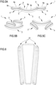
- the articulation skeleton 11 is configured to assume a plurality of configurations obtainable by means of relative angular movement between the shin guard modules 2, 3, 4 (in this regard, see figures 5A, 5B and 5C ). Being in flexible or swivel material, the articulation skeleton 11 allows the shin guard 1 to adapt optimally to the shape of the shin of the user in such a way as to prevent the creation of space between the shin guard 1 and the shin, avoiding the movement of the shin guard 1, which would create actually unwanted sliding between the shin guard 1 and the shin, irritating the skin and annoying the user.
- the articulation skeleton 11 is advantageously made of elastic material.
- the articulation skeleton 11 is made of elastically deformable material, since providing elastically deformable material allows the articulation skeleton 11 to deform reversibly and to move, therefore, the shin guard modules 2, 3, 4 reversibly.
- the articulation skeleton 11 can be made of at least partially or predominantly rubbery material.
- the articulation skeleton 11 is configured to angularly move the first, the second and the third shin guard module 2, 3, 4 with respect to each other; thus, the articulation skeleton 11 allows to provide flexibility and adaptability of use to the shin guard 1.
- figure 5A where the shin guard 1 is in an open configuration wherein the second and third shin guard modules 3, 4 are unfolded with respect to the first shin guard module 2 to form a concavity of the shin guard 1 configured to accommodate, when in use, the shin of the user
- figure 5B where the second and third shin guard modules 3, 4 are folded over the first shin guard module 2 to form a kinked configuration of the shin guard 1
- figure 5C where the second and third shin guard modules 3, 4 are unfolded even further with respect to the open configuration of figure 5A to define a fully open configuration.
- the open configuration of figure 5A is an intermediate configuration between the kinked configuration of figure 5B and the fully open configuration of figure 5C .
- the open configuration of figure 5A can be obtained by unfolding, starting from the kinked configuration of figure 5B , the second and third shin guard module 3, 4 moving away from the first shin guard module 2 and the fully open configuration shown in figure 5C can be obtained by unfolding even further, starting from the open configuration of figure 5A , the second and the third shin guard module 3, 4 with respect to the first shin guard module 2.
- the open configuration of figure 5A can be obtained by folding, starting from the fully open configuration of figure 5C , the second and third shin guard module 3, 4 towards the first shin guard module 2, and the kinked configuration of figure 5B can be obtained by folding even further, starting from the configuration of figure 5A , the second and the third shin guard module 3, 4 towards the first shin guard module 2 until at least one of the second and third shin guard module 3, 4 stops against the first shin guard module 2.
- the articulation skeleton 11 can be constituted by the assembly of a plurality of single elements separated from each other or, alternatively, by a single-piece element, which can reproduce a more complex geometry.
- the articulation skeleton 11 comprises at least one coupling band 12', 12", 12′′′ which connects to each other at least the first and the second shin guard module 2, 3. Devising at least one coupling band 12', 12", 12′′′ allows to provide an articulated constraint to the shin guard 1 aimed at improving the shape adaptability of the shin guard 1, optimizing the relative movement between the shin guard modules 2, 3, 4.
- a coupling band 12', 12", 12′′′ is described, connecting the first, the second and third shin guard modules 2, 3, 4.
- the coupling band 12', 12", 12′′′ is configured for connecting further shin guard modules 1 together.
- the coupling band 12', 12", 12′′′ allows to engage the padding elements 9 to the respective protective elements 5.
- the coupling band 12', 12", 12′′′ comprises a first coupling portion 12a, a second coupling portion 12b and a third coupling portion 12c; the first coupling portion 12a is interposed between the second coupling portion 12b and the third coupling portion 12c.
- the first coupling portion 12a can be defined in correspondence of a central portion of the coupling band 12', 12", 12′′′ while the second and third coupling portions 12b, 12c can be defined in correspondence of opposite ends of the coupling band 12', 12", 12'".
- the first coupling portion 12a is advantageously housed in correspondence of the seat 8b of the protective element 5 of the first shin guard module 2 and engages the padding element 9 of the first shin guard module 2 to the protective element 5 of the first shin guard module 2.
- the second and third coupling portions 12b, 12c can be housed respectively in correspondence of the seats 8a, 8c of the protective elements 5 of second shin guard module 3 and of the third shin guard module 4 and engage the padding element of the second shin guard module 3 and of the third shin guard module 4 respectively to the protective element 5 of the second shin guard module 3 and the third shin guard module 4.
- Each coupling band 12', 12", 12′′′ further comprises at least one connector 12d connecting to each other coupling portions 12a, 12b, 12c adjacent to the coupling band 12', 12", 12′′′.
- Each connector 12d can be separated with respect to the coupling portions 12a, 12b, 12c of the coupling band 12', 12", 12′′′ or can be integrated with the coupling portions 12a, 12b, 12c of the coupling band 12', 12", 12′′′.
- each coupling band 12', 12", 12′′′ is monolithic (meaning that coupling portions 12a, 12b, 12c of the same coupling band 12', 12", 12′′′ are part of a single piece) and each connector 12d integrated with the coupling portions 12a, 12b, 12c of the coupling band 12', 12", 12′′′ and is formed by a portion of the coupling band 12', 12", 12′′′ interposed between the adjacent coupling portions 12a, 12b, 12c.
- the width of the connectors 12d is a reduced width compared to the prevailing width of the coupling bands 12', 12", 12'", so as to improve the articulation between the shin guard modules 2, 3, 4.
- each coupling band 12', 12", 12′′′ is monolithic (made up of a respective piece), distinct and separated from the other coupling bands 12', 12", 12′′′ (see figure 3 ). Instead, in the second example all the coupling bands 12', 12", 12′′′ are part of a single monolithic articulation skeleton 11 (see figure 4 ).
- the articulation skeleton 11 can comprise at least a first coupling band 12' and a second coupling band 12", each of which may be of the type described above.
- the first coupling band 12' and the second coupling band 12" are spaced apart and are engaged, by means of the aforementioned coupling portions 12a, 12b, 12c, to each protective element 5 of said shin guard modules 2, 3, 4, by means of the respective coupling portions 12a, 12b, 12c, in correspondence of respective portions of the same protective element 5 longitudinally spaced apart.
- the first coupling band 12' and the second coupling band 12" can be engaged to the respective protective elements 5 in correspondence of two of the central portion 5c, the first end portion 5a and the second end portion 5c.
- Providing at least one first coupling band 12' and at least a second coupling band 12" engaged in correspondence of respective portions of the same protective element 5 longitudinally spaced apart allows to provide two articulated constraints designed to optimally control the articulation performance of the shin guard 1, optimizing the relative movement between shin guards modules 2, 3, 4.
- the first coupling band 12' can be engaged to the protective elements 5 in correspondence of one of the first and the second end portion 5a, 5b and the second coupling band 12" can be engaged in correspondence of the central portion 5c of the protective element 5 (see figures 3 and 4 ), while in another example the first coupling band 12' is engaged to the protective elements 5 in correspondence of the first end portion 5a and the second coupling band 12" is engaged to the protective elements 5 in correspondence of the second end portion 5b or vice versa.
- the articulation skeleton 11 also comprises further coupling bands 12"'.
- the articulation skeleton 11 can comprise at least a third coupling band 12′′′ of the previously described type.
- the first coupling band 12', the second coupling band 12" and the third coupling band 12′′′ are engaged to the protective elements 5 in correspondence of respective seats bands.
- the first coupling band 12' can be engaged in correspondence of the seats band defined in correspondence of the first end portion 5a of the protective elements 5
- the second coupling band 12" can be engaged in correspondence of the seats band defined in correspondence of the central portion 5 of the protective elements
- the third coupling band 12′′′ can be engaged in correspondence of the seats band defined in correspondence of the second end portion 5b of the protective elements 5; in this regard, see figures 3 and 4 .
- Providing a first coupling band 12', a second coupling band 12" and a third coupling band 12′′′ engaged as just described to the protective elements 5 allows to provide three articulated constraints aimed at controlling optimally the articulation performances of the shin guard 1, optimizing the relative movement between shin guard modules 2, 3, 4.
- the coupling bands 12', 12", 12′′′ are engaged in correspondence of seats 8a, 8b 8c, of the protective elements 5, so as to arrange the shin guard modules 2, 3, 4 to form a gap 13 between them.
- a respective gap 13 is formed between adjacent individual shin guard modules 2, 3, 4; between the first shin guard module 2 and the second shin guard module 3 a gap 13 is formed and between the first shin guard module 2 and the third shin guard module 4 another gap 13 is formed.
- gaps 13 preferably have one same characteristic dimension, such as a width of the gap 13, which can be defined as the distance between the outer facing longitudinal edges 6 of the shin guard modules 2, 3, 4.
- the connectors 12d of the coupling bands 12', 12", 12′′′ develop over the gaps and allow, by moving at least one shin guard module 2, 3, 4, to angularly offset the shin guards modules 2, 3, 4 with respect to one another.
- the connectors 12d functionally act as hinges and allow angular movement by rotation of the shin guards modules 2, 3, 4 with respect to one another.
- the first example illustrated in the accompanying figures illustrates an articulation skeleton 11 comprising three coupling bands 12', 12", 12′′′ distinct and separated from each other, while the second example comprises an articulation skeleton 11 of the monolithic type, wherein the coupling bands 12', 12", 12′′′ are connected to each other (see figure 4 ).
- the articulation skeleton 11 can comprise a body 11a. As shown in figure 4 , the body 11a connects the first coupling band 12', the second coupling band 12" and the third coupling band 12′′′.
- the body 11a develops substantially parallel to at least one protective element 5 along a longitudinal direction and transversely to the first coupling band 12', to the second coupling band 12" and to the third coupling band 12".
- the body 11a is preferably joined to the protective element 5 of the first shin guard module 2. As shown in figure 4 , the body 11a has a smaller width than a width of the protective element 5 of the central shin guard module 2.
- connection seats 77a and 77b are advantageously obtained on the protective element 5, departing without solution of continuity between the seats 8a, 8b, 8c, so that the assembly of seats on the protective element 5 displays a geometry corresponding to the geometry of the articulation skeleton 11.
- the shin guards 1 according to the present invention can be provided in various sizes. Specific sizes can be obtained, for example, according to the target user for whom the shin guard 1 is conceived.
- the shin guards 1 can be provided in three different sizes (for example one child size, one adult size and one women size); such sizes can differ in the characteristic dimensions of the shin guard modules 2, 3, 4 and its components (such as the protective elements 5 and the padding elements 9).
- the number of coupling bands 12', 12", 12′′′ or the distance between coupling bands 12', 12", 12′′′ can vary.
- the shin guards 1 can be provided in various versions. Versions can be provided, for example, depending on the sport for which the shin guard is conceived. For example, the shin guards 1 can be provided in a football version, in a hockey version, in a baseball version, in a cricket version, and so on.
- These versions can differ in at least one of the following: characteristic dimensions of the shin guard modules 2, 3, 4 and their components (such as the protective elements 5 and the padding elements 9), constituent materials of the shin guard modules 2, 3, 4 and related components, such as constituent materials of the protective elements 5, of the padding elements 9 and, if present, of the shells 10, the possible presence of a shell 10, or similar considerations related to the peculiarity of each sport and the foreseeable intensity of possible impacts that the shin of the user may suffer when practicing a particular sport.
- the present disclosure further provides a use of the shin guard 1 previously described.
- the use of the shin guard 1 is intended to protect a shin of a user.
- the use of shin guard 1 can be made in the sports sector, for example in sports such as football, hockey, baseball, cricket and the like. It is understood that the use of the shin guard 1 can be made in any activity, sport or discipline in which the shin of a user can be impacted.
- the use of the shin guard 1 can provide to secure a shin guard 1 to a shin of a user or to secure a pair of shin guards 1, each to a respective shin of the user.
- the use of the shin guard 1 can also provide to adapt, for example by the user, at least one shin guard 1 to the conformation of the respective shin on which it is worn.
- the adaptation of at least one shin guard 1 to the conformation of the shin is carried out by relative movement of the first shin guard module 2 and of the second shin guard module 3 and, optionally and where provided, of the third shin guard module 4.
- the relative movement between shin guard modules 2, 3, 4 is of angular type and provides to angularly offset the shin guard modules 2, 3, 4.
- the adaptation of at least one shin guard 1 to the shape of the shin provides, in addition to the relative movement between shin guard modules 2, 3, 4, also the movement of at least one of the first shin guard module 2, the second shin guard module 3 and, optionally and where provided, the third shin guard module 4 with respect to the shin of the user.
- the present disclosure also relates to a kit comprising a pair of shin guards 1 of the type described above.
- the pair of shin guards 1 comprise a first shin guard 1 of the modular type and a second shin guard 1 of the modular type configured to be secured, when in use, to a respective shin of a user.
- the present disclosure also relates to a manufacturing process of a shin guard 1 of the type described above.
- the process provides to arrange shin guard modules 2, 3, 4 of the type described above, and in particular at least a first shin guard module 2, a second shin guard module 3 and also a third shin guard module 4.
- the step of arranging each shin guard module 2, 3, 4 provides to arrange a shin guard module 2, 3, 4 comprising at least a protective element 5 of the type previously described.
- Each shin guard module 2, 3, 4 further comprises a padding element 9, of the type previously described, engaged to the protective element 5.
- Each protective element 5 can be made by arranging sheet material and obtaining, for example by blanking the sheet material, a protective element 5.
- each protective element 5 can be made by molding plastic or polymeric material or by melting metallic material.
- the plastic or polymeric or metallic material can be in accordance with what previously described.
- Each padding element 9 can be arranged through engagement between a padding cushion 9a and a respective coating 9b, both of the type described above; such engagement can be made by means of adhesive material, such as glue or double-sided tape.
- the step of arranging each shin guard module 2, 3, 4 can provide to join the padding element 9 to the protective element 5 by using adhesive material, such as glue or double-sided tape.
- the engagement of the padding element 9 to the protective element 5 provides to join the padding cushion 9a to the protective element 5 so that the padding cushion 9a is interposed between the protective element 5 and the coating 9b.
- the method also provides to arrange an articulation skeleton 11 of the type described above.
- the procedure provides to engage the articulation skeleton 11 with the protective elements 5 of the first shin guard module 2, the second shin guard module 3 and, where provided, the third shin guard module 4.
- the step of engaging the articulation skeleton 11 is preferably carried out prior to the step that provides to engage, for each shin guard module 2, 3, 4, the respective padding element 9 to the respective protective element 5.
- the articulation skeleton 11 is engaged to the protective elements 5 and subsequently the padding elements 9 are engaged to the respective protective elements 5.
- the articulation skeleton 11 of the shin guard 1 is interposed between the protective elements 5 and the respective padding elements 9.
- the connection of the articulation skeleton 11 to the shin guard modules 2, 3, 4 provides to engage the coupling portions in correspondence of the respective seats 8a, 8b, 8c, in accordance to what was previously described.
- engaging the articulation skeleton 11 to the shin guard modules 2, 3, 4 also provides for engaging the body 11a to the protective element 5 of the first shin guard module 2.
- Providing an articulation skeleton 11 equipped with a body 11a engaged to the coupling bands 12', 12", 12′′′ allows to engage the articulation skeleton 11 to the protective elements 5 by means of a single coupling operation.
- the method can further provide to arrange at least one shell 10 and to couple, in a removable or non-removable way, the shell 10 to the protective element 5 of a shin guard module 2, 3, 4, such as the central shin guard module 2.
- the process can also provide for arranging additional shells 10 and to couple, in a removable or non-removable way, each shell 10 to the protective element 5 of a respective shin guard module 2, 3, 4.
- Coupling a shell 10 to a protective element 5 of a shin guard module 2, 3, 4 provides to engage the shell 10 in correspondence of a surface of the protective element 5 which is opposite to the surface of the protective element 5 in correspondence of which the padding element 9 is engaged, in such a way that the protective element 5 is interposed between the shell 10 and the padding element 9.
- the present invention allows to obtain a shin guard 1 which appears to be adaptable to a plurality of possible different conformations of the shin of a user.
- the invention allows to obtain a shin guard 1 adaptable to the shin of a plurality of users. Therefore, the invention provides a shin guard 1 that can be worn by a plurality of users.
- the invention presents a shin guard 1 that is light and at the same time robust and capable to dampen and/or absorb forces deriving from impacts and therefore able to protect effectively, when in use, the shin of a user.
- the total weight of protective element 5 and padding element 9 can be between 40 and 50 grams, in particular equal to about 46 grams.
- the present invention also provides a shin guard 1 which can be comfortably worn by a plurality of users.
- the shin guard 1 according to the invention can be worn by a user by offering optimal freedom of movement to users, who may not even notice that they are wearing it.
- the shin guard 1 is capable, by means of the articulation skeleton 11, to adapt optimally to the conformation of the shin of the user in such a way that prevents the creation of space between the shin guard 1 and the shin, avoiding the movement of the shin guard 1, a movement which, if present, would in fact create an unwanted sliding between shin guard 1 and the shin, which would cause annoying irritation of the skin of the user.
- the invention therefore provides a shin guard 1 which is comfortable to wear and does not irritate the skin of the user.
- the present invention fully achieves its purpose to provide a shin guard that always ensures an optimal fit and consequently prevents the onset of irritation and injuries to those who wear this shin guard.
- the modular configuration of the shin guard maximizes the adaptability of the shin guard to the shape of the shin of the user.
Landscapes
- Health & Medical Sciences (AREA)
- General Health & Medical Sciences (AREA)
- Physical Education & Sports Medicine (AREA)
- Engineering & Computer Science (AREA)
- Textile Engineering (AREA)
- Professional, Industrial, Or Sporting Protective Garments (AREA)
Description
- The present invention relates to a shin guard.
- The invention also relates to a process for making a shin guard.
- The invention can find advantageous application in the sports sector and in particular in sports where shin guards are usually employed. Examples of such sports are football, five-a-side football, hockey, baseball, cricket, American football and the like.
- It is known that shin guards are generally used to protect the shins of users (athletes or not) during the practice of sports where an impact could cause trauma or even serious consequences on the lower limbs of users. Examples of such shin guards can be found in documents of known art
US4627108 ,US5732411 andUS5829055 . - Known types of shin guards comprise a one-piece protective shield; such shin guards can be inserted in special socks in correspondence with a suited pocket. Basically, in order to use these shin guards, the user must wear special socks too; this can be uncomfortable in certain sports. Moreover, if these socks are not available, these shin guards become substantially unusable.
- Known types of shin guards also comprise an external one-piece protective shield and an internal rubber lining apt to come into contact, when the shin guards are in use, with the shins of the user. Such shin guards can be secured to the lower limbs by means of proper strap bands, which are usually mutually fastened to the height of the calf of the user.
- Some shin guards also have an anklet that can be worn by the user and that ensures a more stable positioning of the shin guard on the lower limb of the user, preventing annoying upward and downward movements of the shin guard when it is in use.
- The known types of shin guards turn out to be awkward to wear and do not guarantee the necessary comfort to users. In particular, the known types of shin guards do not fit optimally, so that, not adhering perfectly to the shin of the user, they rub on the skin of the user, thus causing annoying irritations and even injuries.
- Document
US6,065,152 , which discloses the preamble ofclaim 1, discloses a shin guard divided into a central pad and a pair of lateral pads, intended to protect the user's shin from frontal impacts and from external impacts and internal impacts respectively. The internal lateral pad has a reduced extension with respect to the external lateral pad. Each pad of the shin guard comprises an outer layer of mesh material, an inner layer of resilient foam material and an intermediate layer of rigid material. A flexible joint engages the separation zone between two adjacent portions of the shin guard, being stitched by means of seams to the edges of the outer and inner layers. - Document
US2017/0217126A1 discloses a foam structure that includes a plurality of hexagonal columnar elements, separated from each other by an interspace increasing air permeability. Each columnar element comprises an upper layer and a lower layer both in foam material and an intermediate piece whose opposite faces adhere to the upper layer and to the lower layer respectively. The intermediate pieces are connected with each other by means of connecting segments crossing the interstices between the columnar elements. In order to better withstand to external forces and vibrations, the intermediate pieces and the connecting segments are formed integrally. - The object of the present invention is therefore to solve at least one of the drawbacks and/or limitations of the previous solutions.
- A first object of the present invention is to provide a shin guard that can be worn comfortably by a user and at the same time provide excellent protection to a shin of a user.
- In particular, the present invention aims to provide a shin guard that, by ensuring optimal fit at all times, can prevent the onset of irritation and even injury to the user.
- It is also an object of the present invention to provide a shin guard that can be used by a plurality of users.
- It is an additional object of the present invention to provide a shin guard that is both light and strong, so that it can be worn by a user with a high comfort and may ensure at the same time an effective protection from impacts.
- It is also an object of the present invention to provide a simple and efficient process of making a shin guard.
- Furthermore, it is an object of the invention to provide a shin guard which can guarantee adequate performance even at low or high temperatures, maintaining in particular its breathability and its impact resistance.
- Furthermore, the present invention is functional to allow customization also in the aesthetic rendering of the shin guard.
- The objects described above with reference to a shin guard and the process of making a shin guard are shared by a use of a shin guard and a kit.
- These and other objects, which will become clearer from the following description, are substantially achieved by a shin guard, by a process of making a shin guard, by a use of a shin guard and by a kit.
- Some embodiments and some aspects of the invention as defined by the claims, will be hereafter described with reference to the accompanying drawings, provided only for explanatory and therefore non-limiting purposes, wherein:
-
figure 1 is a front view of a shin guard according to a first embodiment of the present invention, -
figure 2 is a rear view of the shin guard offigure 1 , -
figure 3 illustrates a shin guard during a step of the manufacturing process of the shin guard according to the first embodiment of the present invention, this step being in particular preliminary to the connection of the padding elements with the respective protective elements, which are illustrated in a rear view, -
figure 4 shows an exploded view of a shin guard according to a second embodiment of the present invention, -
figures 5A, 5B and 5C are views of possible configurations of the shin guard that can be assumed both by a shin guard according to the first embodiment of the present invention, and by a shin guard in accordance with the second embodiment of the present invention, -
figure 6 is a view of shells which can be engaged from the front to respective protective elements of a shin guard according to the first or second embodiment of the present invention. - In the present detailed description corresponding illustrated parts in various figures are indicated with the same numerical references. The figures could illustrate the object of the invention by means of not-to-scale representations; therefore, parts and components illustrated in the figures relating to the object of the invention could concern only schematic representations. In the context of this description, the use of terms such as "above", "upper", "higher", "below", "lower", "on the side", "side", "laterally", "horizontal", "horizontally", "vertical", "vertically", "front", "frontally", "rear", "posteriorly" and similar refer, unless otherwise specified, to at least one spatial orientation that normally the object of the invention can adopt in operating conditions or in conditions of use. In this regard, see the attached figures illustrating at least one possible spatial orientation of the object of the invention; in particular, see
figures 1, 2 and3 illustrating the vertical spatial orientation that a shin guard in accordance to the invention can assume when in use. - Hereinbelow are some definitions that can be used to understand of the present invention:
- the term "shin guard" indicates an item, for example a technical and/or sport item, or a device configured to protect a shin of a user from possible impacts,
- the expression "shin guard module" indicates a modular element of the shin guard. Each shin guard module can comprise assembled components and/or components that can be assembled. Optionally, the shin guard modules can differ from each other due to their shape; for example, adjacent shin guard modules can be complementary in shape.
- In the attached figures, the
numerical reference 1 overall indicates a shin guard according to the present invention. - The
shin guard 1 is of the modular type. As will be seen in greater detail below, the modularity of theshin guard 1 allows it to adapt to the various shin conformations of a plurality of users. In other words, the modularity of theshin guard 1 allows it to be used by a plurality of users; therefore, theshin guard 1 of the modular type has a wide range of possible uses. - The
shin guard 1 of the modular type comprisesshin guard modules shin guard 1 comprises at least a firstshin guard module 2 and a secondshin guard module 3. Eachshin guard module shin guard 1 comprising a firstshin guard module 2, a secondshin guard module 3 and a thirdshin guard module 4. The number ofshin guard modules shin guard modules shin guard 1 to the shin of a user increases too; this is possible because, as will be seen in greater detail below, theshin guard modules shin guard modules shin guard module shin guard modules shin guard 1 having a minor number ofshin guard modules shin guard modules shin guard modules shin guard modules shin guard 1 allows to cover and protect a larger area of the shin of a user (greater surface of the shin with respect to the surface protected by a shin guard having a smaller number ofshin guard modules - In the embodiments illustrated in the attached figures, the first shin guard module is substantially a central
shin guard module 2 and the second shin guard module and the third shin guard module are lateralshin guard modules shin guard module 2. The centralshin guard module 2 and the lateralshin guard modules shin guard modules shin guard 1 to have a greater width in correspondence of its upper end when compared to the width which it exhibits in correspondence of its own lower end. The upper end and lower end of theshin guard 1 are intended to be respectively positioned, when theshin guard 1 is in use and with reference to body parts of the user, in correspondence of an upper part of the shin close to the knee of the user and in correspondence of a lower part of the shin close to the ankle of the user. The upper end and the lower end of the shin guard are defined with reference to the orientation that theshin guard 1 assumes in its operative configuration; in this regard, seefigures 1, 2 and3 . Ashin guard 1 is described below, whosemodules shin guard module 2 can have a tapered conformation which tapers from one end to the other of the centralshin guard module 2, while the lateralshin guards modules shin guard module shin guard modules shin guard module 2. Being the lateralshin guard modules shin guard module 2, the lateralshin guard modules shin guard 1 to have at its upper end a greater width than the width it exhibits in correspondence of its lower end. - A
shin guard module shin guard module shin guard module shin guard module shin guard 1. - The
shin guard module protective element 5. Theprotective element 5 substantially acts as a shield configured to dampen and/or absorb forces deriving from any possible impacts that can occur on theshin guard module shin guard 1 is in use, and thus protects at least one portion of the shin of the user. As illustrated in the attached figures, theprotective element 5 has an elongated conformation defined along a longitudinal direction. Having an elongated conformation allows theprotective element 5 to cover and protect, when theshin guard 1 is in use, a predominant portion or entirely the respective longitudinal portion of a shin of a user. Theprotective element 5 develops longitudinally between afirst end portion 5a and asecond end portion 5b and has acentral portion 5c interposed between thefirst end portion 5a and thesecond end portion 5b. Theprotective element 5 haslongitudinal edges 6 extending longitudinally andtransversal edges 7, extending transversely with respect to thelongitudinal edges 6. Thetransversal edges 7 can be at least partially arched. Theprotective element 5 with elongated conformation has a greater length than its own width; the length of theprotective element 5 can be defined as the distance between longitudinally opposedtransversal edges 7, while the width of theprotective element 5 can be defined in correspondence of a longitudinal center line of the protective element 5 (half-length of the protective element 5) as the distance between the oppositelongitudinal edges 6. For example, the length of theprotective element 5 can be at least equal to the double or triple width of theprotective element 5. Theprotective element 5 can have an at least partially concave profile (seefigure 4 ), which allows theprotective element 5 to adapt, when theshin guard 1 is in use, to the conformation of the respective longitudinal portion of the shin of a user. Eachprotective element 5 can advantageously comprise at least oneseat seat protective element 5 develops. As shown in the attached figures, theseat protective element 5 of the centralshin guard module 2 can extend unbrokenly across oppositetransversal edges 7 substantially separated by an entire width of theprotective element 5, while theseat protective elements 5 of the lateralshin guard modules protective element 1 adjacent to the centralshin guard module Respective seats protective elements 2 and lateralprotective elements protective element - See
figure 4 , from which it can be noted that theseats connection seats seats protective element 5 preferably comprises at least twoseats first end portion 5a,second end portion 5b andcentral portion 5c) of theprotective element 5. In this regard,figure 4 showsprotective elements 5, each provided with threeseats protective element 5 has afirst seat 8a defined in correspondence of thefirst end portion 5a, asecond seat 8b defined in correspondence of thecentral portion 5c and athird seat 8c defined in correspondence of thesecond end portion 5b.Figure 4 shows threeprotective elements 5, one for each of theshin guard modules shin guard 1 is in use, three seat bands longitudinally spaced apart from each other wherein each band comprises arespective seat protective element 5 arranged in correspondence of a corresponding portion of theprotective elements 5. In particular, a first seat band is defined in correspondence of thefirst end portions 5a and comprises thefirst seats 8a of theprotective elements 5 of theshin guard modules central portions 5c and comprises thesecond seats 8b of theprotective elements 5 of theshin guard modules second end portions 5b and comprises thethird seats 8c of theprotective elements 5 of theshin guard modules - Each
protective element 5 is preferably monolithic. Eachprotective element 5 is preferably made of material whose rigidity is such that it allows theprotective element 5 to damper and/or absorb forces deriving from impacts that can occur when theshin guard 1 is in use without plastically deforming and without breaking. - In one example, each
protective element 5 can be made in plastic or polymeric material; for example, eachprotective element 5 can be made of polyamide, such as nylon. In an alternative example, eachprotective element 5 can be made of metallic material, such as aluminum, steel or titanium. In another alternative example, eachprotective element 5 can be made of leather. In further examples eachprotective element 5 can be partially made of plastic or polymeric material and partially of metallic material or theshin guard 1 can provide at least oneprotective element 5 in plastic or polymeric material and at least oneprotective element 5 made of metallic material so as to differentiate the rigidity of portions of at least oneprotective element 5 or of theprotective elements 5 of theshin guard 1, for example depending on the operating position of theprotective elements 5 or of portions thereof with respect to the shin of the user. Providing at least one of the aforementioned plastic, polymeric, metallic or leather materials allows theprotective element 5 to be light and at the same time resistant to impacts that can occur when theshin guard 1 is in use. Eachprotective element 5 can have a thickness between 1 and 5 mm, in particular between 2 and 3 mm. Preferably, eachprotective element 5 can have a thickness substantially equal to 2.5 mm. Providing a thickness within the thickness ranges described above allows to minimize the material without compromising its impact resistance and therefore allows theprotective element 5 to be light and resistant at the same time. - The
shin guard module padding element 9. Thepadding element 9 is engaged to theprotective element 5; thepadding element 9 and theprotective element 5 can be engaged either directly or by the interposition of a further component. Thepadding element 9 is intended to be interposed, when the shin guard is in use, between theprotective element 5 and the shin of the user. Thepadding element 9 is configured to let the user wear theshin guard 1 comfortably, preventing the shin from coming into direct contact with theprotective element 5. Thepadding element 9 is made of material with lower rigidity than the rigidity of the material of theprotective element 5. The material of thepadding element 9 can deform when in contact with the shin of the user. Thepadding element 9 has plan dimensions equal to or corresponding to or comparable to the plan dimensions of theprotective element 5. The plan dimensions of thepadding element 9 have dimensions, such as length and width, substantially equal or corresponding or comparable to the respective dimensions, such as length and width, of theprotective element 5 to which thepadding element 9 is joined. Such plan dimensions of thepadding element 9 allow it, when manufacturing a single module ofshin guards protective element 5 in correspondence of a prevalent portion of its surface, without it protruding from the plan dimensions of theprotective element 9. - The
padding element 9 comprises apadding cushion 9a and acoating 9b matched together. Thepadding cushion 9a is joined to a respectiveprotective element 5 and is interposed between thecoating 9b and theprotective element 5. Thepadding cushion 9a is made of material configured to absorb and dampen forces deriving from impacts; providing at least onepadding cushion 9a in such material allows the respectiveshin guard module shin guard 1, when in use, to protect the shin of the user from impacts. - For example, the
padding cushion 9a can be made of elastically deformable material, for example in rubber or plastic or polymeric material. In a possible example, thepadding cushion 9a can be of ethylene octane (EPDM). Thepadding cushion 9a can be made of washable material, for example it can be water washed at a temperature close to or equal to 40°C or dry cleaned. Thepadding cushion 9a can be in breathable and water resistant material and, in addition or in alternative, sweat resistant. The material of thepadding cushion 9a can also be impermeable, for example to water and sweat. Thepadding cushion 9a can be attached in such a way that a portion thereof is recessed with respect to edges of theprotective element 5 to which thepadding cushion 9a is attached and one further portion thereof protrudes with respect to these edges. The padding cushion can have a thickness between 2 mm and 10 mm, in particular between 4 mm and 8 mm. Preferably, the thickness of the padding cushion can be substantially equal to 6 mm, of which about 2 mm can be recessed with respect toedges protective element 5 to which thepadding cushion 9a is matched and about 4 mm can protrude from theedges protective element 5. Thepadding cushion 9a and thecoating 9b can be joined by using adhesive material such as glue or double-sided tape. When theshin guard 1 is in use, thecoating 9b is intended to face the shin of the user and to come into contact with it. Similarly to the padding cushion, the coating can be in washable material. The coating can be in polymeric material, such as polyurethane. Thecoating 9b can have a thickness between 0.5 mm and 2 mm, in particular between 0.6 mm and 1.4 mm. Preferably, thecoating 9b can have a thickness substantially equal to 0.8 mm. - The
shin guard module shell 10. Theshell 10 can be integrated or coupled or couplable to theprotective element 5.Figure 6 shows threeshells 10, each of which can be coupled to theprotective element 5 of the firstshin guard module 2, of the secondshin guard module 3 and of the thirdshin guard module 4 respectively, in correspondence of a surface of the respectiveprotective element 5 opposite with respect to the surface of theprotective element 5 in correspondence of which thepadding cushion 9a of thepadding element 9 is engaged. Theshell 10 can be permanently coupled to the respectiveprotective element 5, for example by adhesive material such as glue or double-sided tape or by welding, or it can be removably coupled to the respectiveprotective element 5. - In the example wherein the
shell 10 can be removably coupled to the respectiveprotective element 5, theshell 10 can be coupled to the respectiveprotective element 5 if necessary, for example to increase its rigidity, and can be removed from the respectiveprotective element 5 if necessary. - The
shell 10 is configured to stiffen the respectiveshin guard module shell 10 can be made of the same material with respect to theprotective element 5 or can be made of material having higher rigidity than the material of theprotective element 5. Furthermore, theshell 10 can have similar characteristics in terms of materials and thickness to what previously described for theprotective element 5. Theshell 10 is preferably monolithic. Theshell 10 is preferably made of material whose rigidity is such that it allows theshell 10 to dampen and/or absorb forces deriving from impacts that can occur when the shin guard is in use, without plastically deforming and without breaking. In one example, eachshell 10 can be made in plastic or polymeric material; for example, eachshell 10 can be made of polyamide, such as nylon. In an alternative example, eachshell 10 can be made of metallic material, such as aluminum, steel or titanium. In further examples, eachshell 10 can be partially in plastic or polymeric material and partially in metal material or theshin guard 1 can provide at least ashell 10 in plastic or polymeric material and at least ashell 10 in metallic material so as to differentiate the rigidity of portions of at least oneshell 10 or theshells 10 of theshin guard 1, for example depending on the operative position of theshells 10 or portions thereof with respect to the shin of the user. Providing at least one of the aforementioned plastic, polymeric or metal materials allows theshell 10 to be light and at the same time resistant to impacts that can occur whenshin guard 1 is in use. Eachshell 10 can have a thickness between 1 and 5 mm, in particular between 2 and 3 mm. Preferably, theshell 10 can have a thickness substantially equal to 2.5 mm. Expecting a thickness within the thickness ranges described above allows to minimize the material without compromising its resistance to impacts and therefore allows theshell 10 to be light and resistant at the same time. - In order to optimize the user experience, the outermost component of the
shin guard 1, which can be theshell 10 in the examples of theshin guard 1 which provide theshell 10 or theprotective element 5 in the examples of theshin guard 1 which do not provide theshell 10, can also be personalized or customized, for example by selecting and adding coats of arms, symbols, letters or specific chromatic applications. - The
shin guard 1 further comprises anarticulation skeleton 11. Thearticulation skeleton 11 is made of flexible or swivel material and is engaged at least to the firstshin guard module 2 and to the secondshin guard module 3 in correspondence of respective surfaces. The articulatedskeleton 11 is also engaged to the third shin guard module 5 (see for examplefigure 3 ) or to further shin guard modules. Being in flexible or swivel material, thearticulation skeleton 11 is configured to allow relative movement between the firstshin guard module 2 and the secondshin guard module 3 and also the movement of the thirdshin guard module 4 as regards the first and the secondshin guard module articulation skeleton 11 is configured to assume a plurality of configurations obtainable by means of relative angular movement between theshin guard modules figures 5A, 5B and 5C ). Being in flexible or swivel material, thearticulation skeleton 11 allows theshin guard 1 to adapt optimally to the shape of the shin of the user in such a way as to prevent the creation of space between theshin guard 1 and the shin, avoiding the movement of theshin guard 1, which would create actually unwanted sliding between theshin guard 1 and the shin, irritating the skin and annoying the user. - The
articulation skeleton 11 is advantageously made of elastic material. Preferably, thearticulation skeleton 11 is made of elastically deformable material, since providing elastically deformable material allows thearticulation skeleton 11 to deform reversibly and to move, therefore, theshin guard modules articulation skeleton 11 can be made of at least partially or predominantly rubbery material. - In the examples of the
shin guard 1 illustrated in the attached figures, thearticulation skeleton 11 is configured to angularly move the first, the second and the thirdshin guard module articulation skeleton 11 allows to provide flexibility and adaptability of use to theshin guard 1. In this regard, see:figure 5A where theshin guard 1 is in an open configuration wherein the second and thirdshin guard modules shin guard module 2 to form a concavity of theshin guard 1 configured to accommodate, when in use, the shin of the user,figure 5B where the second and thirdshin guard modules shin guard module 2 to form a kinked configuration of theshin guard 1 andfigure 5C where the second and thirdshin guard modules figure 5A to define a fully open configuration. Basically, the open configuration offigure 5A is an intermediate configuration between the kinked configuration offigure 5B and the fully open configuration offigure 5C . The open configuration offigure 5A can be obtained by unfolding, starting from the kinked configuration offigure 5B , the second and thirdshin guard module shin guard module 2 and the fully open configuration shown infigure 5C can be obtained by unfolding even further, starting from the open configuration offigure 5A , the second and the thirdshin guard module shin guard module 2. Conversely, the open configuration offigure 5A can be obtained by folding, starting from the fully open configuration offigure 5C , the second and thirdshin guard module shin guard module 2, and the kinked configuration offigure 5B can be obtained by folding even further, starting from the configuration offigure 5A , the second and the thirdshin guard module shin guard module 2 until at least one of the second and thirdshin guard module shin guard module 2. - The
articulation skeleton 11 can be constituted by the assembly of a plurality of single elements separated from each other or, alternatively, by a single-piece element, which can reproduce a more complex geometry. Thearticulation skeleton 11 comprises at least onecoupling band 12', 12", 12‴ which connects to each other at least the first and the secondshin guard module coupling band 12', 12", 12‴ allows to provide an articulated constraint to theshin guard 1 aimed at improving the shape adaptability of theshin guard 1, optimizing the relative movement between theshin guard modules - Hereinafter, a
coupling band 12', 12", 12‴ is described, connecting the first, the second and thirdshin guard modules figure 3 , wherein thearticulation skeleton 11 is assembled to theshin guard modules figure 4 , wherein thearticulation skeleton 11 is in exploded view with respect toprotective elements 5 andpadding elements 9. In alternative examples, thecoupling band 12', 12", 12‴ is configured for connecting furthershin guard modules 1 together. Besides connecting theshin guard modules coupling band 12', 12", 12‴ allows to engage thepadding elements 9 to the respectiveprotective elements 5. Thecoupling band 12', 12", 12‴ comprises afirst coupling portion 12a, asecond coupling portion 12b and athird coupling portion 12c; thefirst coupling portion 12a is interposed between thesecond coupling portion 12b and thethird coupling portion 12c. Thefirst coupling portion 12a can be defined in correspondence of a central portion of thecoupling band 12', 12", 12‴ while the second andthird coupling portions coupling band 12', 12", 12'". Thefirst coupling portion 12a is advantageously housed in correspondence of theseat 8b of theprotective element 5 of the firstshin guard module 2 and engages thepadding element 9 of the firstshin guard module 2 to theprotective element 5 of the firstshin guard module 2. Similarly, the second andthird coupling portions seats protective elements 5 of secondshin guard module 3 and of the thirdshin guard module 4 and engage the padding element of the secondshin guard module 3 and of the thirdshin guard module 4 respectively to theprotective element 5 of the secondshin guard module 3 and the thirdshin guard module 4. It is worth noting how the presence ofseats coupling bands 12', 12", 12‴) shall not be considered as an essential characteristic of the present disclosure, since thecoupling bands 12', 12", 12‴ could alternatively be applied (for example by gluing) to one surface of theprotective element 5 devoid of suitable housing means for thecoupling bands 12', 12", 12‴. - Each
coupling band 12', 12", 12‴ further comprises at least oneconnector 12d connecting to eachother coupling portions coupling band 12', 12", 12‴. Eachconnector 12d can be separated with respect to thecoupling portions coupling band 12', 12", 12‴ or can be integrated with thecoupling portions coupling band 12', 12", 12‴. In the figures, eachcoupling band 12', 12", 12‴ is monolithic (meaning thatcoupling portions same coupling band 12', 12", 12‴ are part of a single piece) and eachconnector 12d integrated with thecoupling portions coupling band 12', 12", 12‴ and is formed by a portion of thecoupling band 12', 12", 12‴ interposed between theadjacent coupling portions connectors 12d is a reduced width compared to the prevailing width of thecoupling bands 12', 12", 12'", so as to improve the articulation between theshin guard modules - In the first example, each
coupling band 12', 12", 12‴ is monolithic (made up of a respective piece), distinct and separated from theother coupling bands 12', 12", 12‴ (seefigure 3 ). Instead, in the second example all thecoupling bands 12', 12", 12‴ are part of a single monolithic articulation skeleton 11 (seefigure 4 ). - The
articulation skeleton 11 can comprise at least a first coupling band 12' and asecond coupling band 12", each of which may be of the type described above. The first coupling band 12' and thesecond coupling band 12" are spaced apart and are engaged, by means of theaforementioned coupling portions protective element 5 of saidshin guard modules respective coupling portions protective element 5 longitudinally spaced apart. For example, the first coupling band 12' and thesecond coupling band 12" can be engaged to the respectiveprotective elements 5 in correspondence of two of thecentral portion 5c, thefirst end portion 5a and thesecond end portion 5c. Providing at least one first coupling band 12' and at least asecond coupling band 12" engaged in correspondence of respective portions of the sameprotective element 5 longitudinally spaced apart allows to provide two articulated constraints designed to optimally control the articulation performance of theshin guard 1, optimizing the relative movement betweenshin guards modules protective elements 5 in correspondence of one of the first and thesecond end portion second coupling band 12" can be engaged in correspondence of thecentral portion 5c of the protective element 5 (seefigures 3 and 4 ), while in another example the first coupling band 12' is engaged to theprotective elements 5 in correspondence of thefirst end portion 5a and thesecond coupling band 12" is engaged to theprotective elements 5 in correspondence of thesecond end portion 5b or vice versa. Optionally, thearticulation skeleton 11 also comprisesfurther coupling bands 12"'. For example, as illustrated in the examples offigure 3 and figure 4 , thearticulation skeleton 11 can comprise at least athird coupling band 12‴ of the previously described type. The first coupling band 12', thesecond coupling band 12" and thethird coupling band 12‴ are engaged to theprotective elements 5 in correspondence of respective seats bands. By way of example, the first coupling band 12' can be engaged in correspondence of the seats band defined in correspondence of thefirst end portion 5a of theprotective elements 5, thesecond coupling band 12" can be engaged in correspondence of the seats band defined in correspondence of thecentral portion 5 of the protective elements and thethird coupling band 12‴ can be engaged in correspondence of the seats band defined in correspondence of thesecond end portion 5b of theprotective elements 5; in this regard, seefigures 3 and 4 . Providing a first coupling band 12', asecond coupling band 12" and athird coupling band 12‴ engaged as just described to theprotective elements 5 allows to provide three articulated constraints aimed at controlling optimally the articulation performances of theshin guard 1, optimizing the relative movement betweenshin guard modules - The
coupling bands 12', 12", 12‴ are engaged in correspondence ofseats 8b 8c, of theprotective elements 5, so as to arrange theshin guard modules gap 13 between them. As illustrated in the annexed figures, arespective gap 13 is formed between adjacent individualshin guard modules shin guard module 2 and the second shin guard module 3 agap 13 is formed and between the firstshin guard module 2 and the thirdshin guard module 4 anothergap 13 is formed.Such gaps 13 preferably have one same characteristic dimension, such as a width of thegap 13, which can be defined as the distance between the outer facinglongitudinal edges 6 of theshin guard modules gaps 13, in addition to providing the adequate separation betweenshin guard modules shin guard 1 is in use, cooperates in keeping the skin of the user at least partially or substantially dry from sweat. Theconnectors 12d of thecoupling bands 12', 12", 12‴ develop over the gaps and allow, by moving at least oneshin guard module shin guards modules connectors 12d functionally act as hinges and allow angular movement by rotation of theshin guards modules - Providing
such gaps 13, in correspondence of which a portion of theconnector 12d is arranged (seefigure 1 ), also allows to move theshin guard modules - As previously introduced, the first example illustrated in the accompanying figures (see
figure 3 in particular) illustrates anarticulation skeleton 11 comprising threecoupling bands 12', 12", 12‴ distinct and separated from each other, while the second example comprises anarticulation skeleton 11 of the monolithic type, wherein thecoupling bands 12', 12", 12‴ are connected to each other (seefigure 4 ). In order to connect thecoupling bands 12', 12", 12‴, thearticulation skeleton 11 can comprise abody 11a. As shown infigure 4 , thebody 11a connects the first coupling band 12', thesecond coupling band 12" and thethird coupling band 12‴. Thebody 11a develops substantially parallel to at least oneprotective element 5 along a longitudinal direction and transversely to the first coupling band 12', to thesecond coupling band 12" and to thethird coupling band 12". Thebody 11a is preferably joined to theprotective element 5 of the firstshin guard module 2. As shown infigure 4 , thebody 11a has a smaller width than a width of theprotective element 5 of the centralshin guard module 2. - In order to improve the housing of the
articulation skeleton 11 when comprising thebody 11a,connection seats protective element 5, departing without solution of continuity between theseats protective element 5 displays a geometry corresponding to the geometry of thearticulation skeleton 11. - As regards the geometry of the
articulation skeleton 11, it is evident that what is described herein and/or what is represented in the attached figures (in particular infigure 4 ) is to be understood as a possible example and not as a limitation. It can in fact be hypothesized that further bodies (of analogous configuration to thebody 11a) can join theportions 12b and/or theportions 12c. It can then further be provided that thearticulation skeleton 11 has a significantly different geometry, for example ring shaped, serpentine shaped, and so on. - The
shin guards 1 according to the present invention can be provided in various sizes. Specific sizes can be obtained, for example, according to the target user for whom theshin guard 1 is conceived. For example, theshin guards 1 can be provided in three different sizes (for example one child size, one adult size and one women size); such sizes can differ in the characteristic dimensions of theshin guard modules protective elements 5 and the padding elements 9). According to the size of theshin guard 1, the number ofcoupling bands 12', 12", 12‴ or the distance betweencoupling bands 12', 12", 12‴ can vary. - Furthermore, the
shin guards 1 can be provided in various versions. Versions can be provided, for example, depending on the sport for which the shin guard is conceived. For example, theshin guards 1 can be provided in a football version, in a hockey version, in a baseball version, in a cricket version, and so on. These versions can differ in at least one of the following: characteristic dimensions of theshin guard modules protective elements 5 and the padding elements 9), constituent materials of theshin guard modules protective elements 5, of thepadding elements 9 and, if present, of theshells 10, the possible presence of ashell 10, or similar considerations related to the peculiarity of each sport and the foreseeable intensity of possible impacts that the shin of the user may suffer when practicing a particular sport. - The present disclosure further provides a use of the
shin guard 1 previously described. The use of theshin guard 1 is intended to protect a shin of a user. The use ofshin guard 1 can be made in the sports sector, for example in sports such as football, hockey, baseball, cricket and the like. It is understood that the use of theshin guard 1 can be made in any activity, sport or discipline in which the shin of a user can be impacted. The use of theshin guard 1 can provide to secure ashin guard 1 to a shin of a user or to secure a pair ofshin guards 1, each to a respective shin of the user. The use of theshin guard 1 can also provide to adapt, for example by the user, at least oneshin guard 1 to the conformation of the respective shin on which it is worn. The adaptation of at least oneshin guard 1 to the conformation of the shin is carried out by relative movement of the firstshin guard module 2 and of the secondshin guard module 3 and, optionally and where provided, of the thirdshin guard module 4. The relative movement betweenshin guard modules shin guard modules shin guard 1 to the shape of the shin provides, in addition to the relative movement betweenshin guard modules shin guard module 2, the secondshin guard module 3 and, optionally and where provided, the thirdshin guard module 4 with respect to the shin of the user. - The present disclosure also relates to a kit comprising a pair of
shin guards 1 of the type described above. The pair ofshin guards 1 comprise afirst shin guard 1 of the modular type and asecond shin guard 1 of the modular type configured to be secured, when in use, to a respective shin of a user. - The present disclosure also relates to a manufacturing process of a
shin guard 1 of the type described above. The process provides to arrangeshin guard modules shin guard module 2, a secondshin guard module 3 and also a thirdshin guard module 4. The step of arranging eachshin guard module shin guard module protective element 5 of the type previously described. Eachshin guard module padding element 9, of the type previously described, engaged to theprotective element 5. Eachprotective element 5 can be made by arranging sheet material and obtaining, for example by blanking the sheet material, aprotective element 5. The sheet material can be in plastic or polymeric material or metallic material or leather. In alternative examples, eachprotective element 5 can be made by molding plastic or polymeric material or by melting metallic material. The plastic or polymeric or metallic material can be in accordance with what previously described. Eachpadding element 9 can be arranged through engagement between apadding cushion 9a and arespective coating 9b, both of the type described above; such engagement can be made by means of adhesive material, such as glue or double-sided tape. The step of arranging eachshin guard module padding element 9 to theprotective element 5 by using adhesive material, such as glue or double-sided tape. For eachshin guard module padding element 9 to theprotective element 5 provides to join thepadding cushion 9a to theprotective element 5 so that thepadding cushion 9a is interposed between theprotective element 5 and thecoating 9b. - The method also provides to arrange an
articulation skeleton 11 of the type described above. The procedure provides to engage thearticulation skeleton 11 with theprotective elements 5 of the firstshin guard module 2, the secondshin guard module 3 and, where provided, the thirdshin guard module 4. In the example providing apadding element 9 for eachshin guard module articulation skeleton 11 is preferably carried out prior to the step that provides to engage, for eachshin guard module respective padding element 9 to the respectiveprotective element 5. According to such example, thearticulation skeleton 11 is engaged to theprotective elements 5 and subsequently thepadding elements 9 are engaged to the respectiveprotective elements 5. Thus, at the end of the assembly, for eachshin guard module protective element 5, of thearticulation skeleton 11 and of therespective padding element 9, thearticulation skeleton 11 of theshin guard 1 is interposed between theprotective elements 5 and therespective padding elements 9. The connection of thearticulation skeleton 11 to theshin guard modules respective seats articulation skeleton 11 is provided with abody 11a, engaging thearticulation skeleton 11 to theshin guard modules body 11a to theprotective element 5 of the firstshin guard module 2. Providing anarticulation skeleton 11 equipped with abody 11a engaged to thecoupling bands 12', 12", 12‴ allows to engage thearticulation skeleton 11 to theprotective elements 5 by means of a single coupling operation. - Optionally, the method can further provide to arrange at least one
shell 10 and to couple, in a removable or non-removable way, theshell 10 to theprotective element 5 of ashin guard module shin guard module 2. The process can also provide for arrangingadditional shells 10 and to couple, in a removable or non-removable way, eachshell 10 to theprotective element 5 of a respectiveshin guard module shell 10 to aprotective element 5 of ashin guard module shell 10 in correspondence of a surface of theprotective element 5 which is opposite to the surface of theprotective element 5 in correspondence of which thepadding element 9 is engaged, in such a way that theprotective element 5 is interposed between theshell 10 and thepadding element 9. - As regards the production process of the
shin guard 1, it is easily understood that having a one-piece articulation skeleton 11 (such as for example the skeleton represented infigure 4 ) determines appreciable advantages both as regards the speed of this production process (having a lower number of components to be assembled), both as regards the precision in positioning of thecoupling bands 12', 12", 12‴ (being perfectly spaced within the articulation skeleton 11). - The present invention allows to obtain a
shin guard 1 which appears to be adaptable to a plurality of possible different conformations of the shin of a user. - The invention allows to obtain a
shin guard 1 adaptable to the shin of a plurality of users. Therefore, the invention provides ashin guard 1 that can be worn by a plurality of users. The invention presents ashin guard 1 that is light and at the same time robust and capable to dampen and/or absorb forces deriving from impacts and therefore able to protect effectively, when in use, the shin of a user. In order to provide a lightness span of theshin guard 1 according to the invention, in the example wherein theprotective element 5 is made of polyamide such as nylon, thepadding cushion 9a is in ethylene octane and thecoating 9b is in polyurethane, the total weight ofprotective element 5 andpadding element 9 can be between 40 and 50 grams, in particular equal to about 46 grams. - The present invention also provides a
shin guard 1 which can be comfortably worn by a plurality of users. - Being light and comfortable, the
shin guard 1 according to the invention can be worn by a user by offering optimal freedom of movement to users, who may not even notice that they are wearing it. - The
shin guard 1 according to the invention is capable, by means of thearticulation skeleton 11, to adapt optimally to the conformation of the shin of the user in such a way that prevents the creation of space between theshin guard 1 and the shin, avoiding the movement of theshin guard 1, a movement which, if present, would in fact create an unwanted sliding betweenshin guard 1 and the shin, which would cause annoying irritation of the skin of the user. - The invention therefore provides a
shin guard 1 which is comfortable to wear and does not irritate the skin of the user. - These advantages described with reference to the
shin guard 1 are also shared by the process of making theshin guard 1, the use of theshin guard 1 and the kit in accordance with the present disclosure. - It should be emphasized that the present invention fully achieves its purpose to provide a shin guard that always ensures an optimal fit and consequently prevents the onset of irritation and injuries to those who wear this shin guard. In fact, the modular configuration of the shin guard maximizes the adaptability of the shin guard to the shape of the shin of the user.
Claims (15)
- Shin guard (1) comprising:- a first shin guard module (2) and a second shin guard module (3), adjacent to each other, each shin guard module (2, 3) being specifically configured to protect and/or cover, under normal-use condition of the shin guard (1), a portion of a shin of a user, each shin guard module comprising a protective element (5) having an elongated conformation and a padding element (9) intended to be interposed, under normal-use condition of the shin guard (1), between the protective element (5) and the shin of the user, and- an articulation skeleton (11) in flexible material engaged to the first shin guard module (2) and to the second shin guard module (3) and configured to allow a relative movement between the first shin guard module (2) and the second shin guard module (3) and- a third shin guard module (4), the first shin guard module (2) being interposed between the second shin guard module (3) and the third shin guard module (4),characterised in that the padding element (9) is engaged to the protective element (5) andin that the articulation skeleton (11) is engaged also to the third shin guard module (4), the articulation skeleton (11) being further configured to allow a relative movement between the third shin guard module (4) and the first shin guard module (2).
- Shin guard (1) according to claim 1, wherein the protective element (5) has an at least partially concave profile.
- Shin guard (1) according to claim 1 or to claim 2, wherein the padding element (9) comprises a padding cushion (9a) and a coating (9b) coupled to the padding cushion (9a), the padding cushion (9a) being interposed between the coating (9b) and the protective element (5), the coating (9b) being intended to be facing and/or to come into contact with the shin of the user under normal-use condition of the shin guard (1).
- Shin guard (1) according to anyone of the previous claims, wherein each shin guard module also comprises a shell (10) which can be integrated or coupled to the protective element (5), the shell (10) being configured to stiffen the respective shin guard module, the protective element (5) being interposed between the shell (10) and the padding element (9) in coupling conditions of the shell (10), coats of arms and/or symbols and/or alphanumeric characters and/or chromatic applications being in particular apt to be applied to the shell (10) in order to obtain a customization of said shin guard (1).
- Shin guard (1) according to anyone of the previous claims, wherein the articulation skeleton (11) comprises a first coupling element (12a) and a second coupling element (12b) configured to be engaged respectively to the first shin guard module (2) and to the second shin guard module (3).
- Shin guard (1) according to claim 5, wherein each protective element (5) comprises at least one seat housing a corresponding coupling element (12a, 12b, 12c) of the articulation skeleton (11), said at least one seat of the protective element of the first shin guard module (2) housing the first coupling element and said at least one seat of the protective element of the second shin guard module (3) housing the second coupling element.
- Shin guard according to claim 5 or to claim 6, wherein the articulation skeleton (11) comprises at least one coupling band (12', 12", 12‴) extending transversely with respect to each protective element, the first coupling element being defined by a first coupling portion of said at least one coupling band and the second coupling element being defined by a second coupling portion of said at least one coupling band.
- Shin guard (1) according to claim 7, wherein the articulation skeleton (11) comprises at least a first coupling band (12') and a second coupling band (12") spaced from each other, each coupling band (12', 12") being engaged to each protective element of said shin guard modules, for example by means of respective coupling portions (12a, 12b), in correspondence with respective portions of the same protective element longitudinally spaced apart.
- Shin guard (1) according to claim 8, wherein said articulation skeleton (11) comprises at least one connection portion (11a) developing between said first coupling band and said second coupling band.
- Shin guard (1) according to any one of the preceding claims, wherein the first shin guard module (2) and the second shin guard module (3) are spaced from each other by a gap (13).
- Shin guard (1) according to claim 10, wherein the first shin guard module (2) and the third shin guard module (4) are also spaced from each other by a gap.
- Shin guard (1) according to any one of the preceding claims, wherein the first shin guard module (2) and the second shin guard module (3) are configured to be angularly offset from each other by means of the articulation skeleton (11).
- Shin guard (1) according to any one of the preceding claims, wherein said articulation skeleton (11) has a substantially symmetrical configuration.
- Shin guard (1) according to claim 13, wherein the shin guard (1) is substantially symmetrical overall.
- Process for making a shin guard (1), comprising the steps of:- arranging at least a first shin guard module (2) and a second shin guard module (3),- arranging an articulation skeleton (11) swivelled and/or in flexible material,- engaging the articulation skeleton (11) to the first shin guard module (2) and to the second shin guard module (3),wherein the step of arranging at least a first shin guard module (2) and a second shin guard module (3) comprises arranging, for each shin guard module a protective element (5) having an elongated conformation and a padding element (9) engaged to the protective element (5),wherein the step of arranging at least a first shin guard module (2) and a second shin guard module (3) also involves arranging a third shin guard module (4) andwherein the step of engaging the articulation skeleton (11) to the first shin guard module (2) and to the second shin guard module (3) involves engaging the articulation skeleton (11) to the first shin guard module (2), to the second shin guard module (3) and to the third shin guard module (4) in correspondence of respective surfaces.
Applications Claiming Priority (1)
| Application Number | Priority Date | Filing Date | Title |
|---|---|---|---|
| IT102019000023970A IT201900023970A1 (en) | 2019-12-13 | 2019-12-13 | IMPROVED SHIN GUARDS AND RELEVANT REALIZATION PROCEDURE |
Publications (2)
| Publication Number | Publication Date |
|---|---|
| EP3834644A1 EP3834644A1 (en) | 2021-06-16 |
| EP3834644B1 true EP3834644B1 (en) | 2024-06-05 |
Family
ID=70155043
Family Applications (1)
| Application Number | Title | Priority Date | Filing Date |
|---|---|---|---|
| EP20209919.8A Active EP3834644B1 (en) | 2019-12-13 | 2020-11-25 | Improved shin guard and related manufacturing process |
Country Status (2)
| Country | Link |
|---|---|
| EP (1) | EP3834644B1 (en) |
| IT (1) | IT201900023970A1 (en) |
Family Cites Families (6)
| Publication number | Priority date | Publication date | Assignee | Title |
|---|---|---|---|---|
| FI70123C (en) | 1983-12-29 | 1986-09-15 | Yoko Team Oy | KNAE- OCH BENSKYDD |
| US5732411A (en) | 1996-04-04 | 1998-03-31 | Trace Athletic Corporation | Adjustable guard for the lower leg and shin |
| US6065152A (en) * | 1996-04-19 | 2000-05-23 | Adidas-Salomon Ag | Athletic shin guard |
| US5829055A (en) | 1996-04-23 | 1998-11-03 | Rawlings Sporting Goods Company, Inc. | Protective leg guards |
| US7937768B2 (en) * | 2007-10-18 | 2011-05-10 | Nike, Inc. | Flexible shin guard |
| TWM549692U (en) * | 2016-01-30 | 2017-10-01 | chang-xin Wu | Connection type foam block |
-
2019
- 2019-12-13 IT IT102019000023970A patent/IT201900023970A1/en unknown
-
2020
- 2020-11-25 EP EP20209919.8A patent/EP3834644B1/en active Active
Also Published As
| Publication number | Publication date |
|---|---|
| EP3834644A1 (en) | 2021-06-16 |
| IT201900023970A1 (en) | 2021-06-13 |
Similar Documents
| Publication | Publication Date | Title |
|---|---|---|
| US6427695B1 (en) | Back protection shield | |
| US7237270B2 (en) | Removable garment protective assembly | |
| US10092044B2 (en) | Protective garment with separate inner and outer shells | |
| US11850501B2 (en) | Protective apparatus with grooves | |
| US20030046747A1 (en) | Energy absorbing protective device that protects areas of articulation | |
| US20130269075A1 (en) | Conformable device for protecting a joint area of the human body | |
| JP2008520848A (en) | Protective device | |
| US20130000025A1 (en) | Seat pad for cycling garment | |
| EP0876772B1 (en) | Wrist guard | |
| US6374409B1 (en) | Accessory providing protection against falls in sports such as in-line skating | |
| US7523508B2 (en) | Hockey pants | |
| EP3439757B1 (en) | Discrete shoulder sleeve for a shoulder-pad system | |
| EP2768332B1 (en) | Neck collar | |
| WO2016138036A1 (en) | Anatomically adaptive joint protector | |
| TW201737977A (en) | Two-piece articulating chest protector with stretchable hinge | |
| US11179260B2 (en) | Knee brace devices, systems and methods | |
| US20040103466A1 (en) | High strength impact resistant knee protector | |
| EP3834644A1 (en) | Improved shin guard and related manufacturing process | |
| US20240365892A1 (en) | Knee brace | |
| WO1990014807A1 (en) | Improvements relating to joint support devices | |
| JP3188936B2 (en) | Sports buttocks protector | |
| CA2517311C (en) | Hockey pants | |
| AU2004202183A1 (en) | Joint protector |
Legal Events
| Date | Code | Title | Description |
|---|---|---|---|
| PUAI | Public reference made under article 153(3) epc to a published international application that has entered the european phase |
Free format text: ORIGINAL CODE: 0009012 |
|
| STAA | Information on the status of an ep patent application or granted ep patent |
Free format text: STATUS: THE APPLICATION HAS BEEN PUBLISHED |
|
| AK | Designated contracting states |
Kind code of ref document: A1 Designated state(s): AL AT BE BG CH CY CZ DE DK EE ES FI FR GB GR HR HU IE IS IT LI LT LU LV MC MK MT NL NO PL PT RO RS SE SI SK SM TR |
|
| STAA | Information on the status of an ep patent application or granted ep patent |
Free format text: STATUS: REQUEST FOR EXAMINATION WAS MADE |
|
| 17P | Request for examination filed |
Effective date: 20211216 |
|
| RBV | Designated contracting states (corrected) |
Designated state(s): AL AT BE BG CH CY CZ DE DK EE ES FI FR GB GR HR HU IE IS IT LI LT LU LV MC MK MT NL NO PL PT RO RS SE SI SK SM TR |
|
| RIC1 | Information provided on ipc code assigned before grant |
Ipc: A41D 13/05 20060101ALI20230315BHEP Ipc: A63B 71/12 20060101ALI20230315BHEP Ipc: A63B 71/06 20060101ALI20230315BHEP Ipc: A41D 13/015 20060101AFI20230315BHEP |
|
| GRAP | Despatch of communication of intention to grant a patent |
Free format text: ORIGINAL CODE: EPIDOSNIGR1 |
|
| STAA | Information on the status of an ep patent application or granted ep patent |
Free format text: STATUS: GRANT OF PATENT IS INTENDED |
|
| INTG | Intention to grant announced |
Effective date: 20230517 |
|
| P01 | Opt-out of the competence of the unified patent court (upc) registered |
Effective date: 20230519 |
|
| GRAJ | Information related to disapproval of communication of intention to grant by the applicant or resumption of examination proceedings by the epo deleted |
Free format text: ORIGINAL CODE: EPIDOSDIGR1 |
|
| STAA | Information on the status of an ep patent application or granted ep patent |
Free format text: STATUS: REQUEST FOR EXAMINATION WAS MADE |
|
| INTC | Intention to grant announced (deleted) | ||
| GRAP | Despatch of communication of intention to grant a patent |
Free format text: ORIGINAL CODE: EPIDOSNIGR1 |
|
| STAA | Information on the status of an ep patent application or granted ep patent |
Free format text: STATUS: GRANT OF PATENT IS INTENDED |
|
| INTG | Intention to grant announced |
Effective date: 20240116 |
|
| GRAS | Grant fee paid |
Free format text: ORIGINAL CODE: EPIDOSNIGR3 |
|
| GRAA | (expected) grant |
Free format text: ORIGINAL CODE: 0009210 |
|
| STAA | Information on the status of an ep patent application or granted ep patent |
Free format text: STATUS: THE PATENT HAS BEEN GRANTED |
|
| AK | Designated contracting states |
Kind code of ref document: B1 Designated state(s): AL AT BE BG CH CY CZ DE DK EE ES FI FR GB GR HR HU IE IS IT LI LT LU LV MC MK MT NL NO PL PT RO RS SE SI SK SM TR |
|
| REG | Reference to a national code |
Ref country code: CH Ref legal event code: EP |
|
| REG | Reference to a national code |
Ref country code: DE Ref legal event code: R096 Ref document number: 602020031910 Country of ref document: DE |
|
| REG | Reference to a national code |
Ref country code: IE Ref legal event code: FG4D |
|
| REG | Reference to a national code |
Ref country code: LT Ref legal event code: MG9D |
|
| PG25 | Lapsed in a contracting state [announced via postgrant information from national office to epo] |
Ref country code: BG Free format text: LAPSE BECAUSE OF FAILURE TO SUBMIT A TRANSLATION OF THE DESCRIPTION OR TO PAY THE FEE WITHIN THE PRESCRIBED TIME-LIMIT Effective date: 20240605 |
|
| REG | Reference to a national code |
Ref country code: NL Ref legal event code: MP Effective date: 20240605 |
|
| PG25 | Lapsed in a contracting state [announced via postgrant information from national office to epo] |
Ref country code: FI Free format text: LAPSE BECAUSE OF FAILURE TO SUBMIT A TRANSLATION OF THE DESCRIPTION OR TO PAY THE FEE WITHIN THE PRESCRIBED TIME-LIMIT Effective date: 20240605 Ref country code: HR Free format text: LAPSE BECAUSE OF FAILURE TO SUBMIT A TRANSLATION OF THE DESCRIPTION OR TO PAY THE FEE WITHIN THE PRESCRIBED TIME-LIMIT Effective date: 20240605 |
|
| PG25 | Lapsed in a contracting state [announced via postgrant information from national office to epo] |
Ref country code: GR Free format text: LAPSE BECAUSE OF FAILURE TO SUBMIT A TRANSLATION OF THE DESCRIPTION OR TO PAY THE FEE WITHIN THE PRESCRIBED TIME-LIMIT Effective date: 20240906 |
|
| PG25 | Lapsed in a contracting state [announced via postgrant information from national office to epo] |
Ref country code: ES Free format text: LAPSE BECAUSE OF FAILURE TO SUBMIT A TRANSLATION OF THE DESCRIPTION OR TO PAY THE FEE WITHIN THE PRESCRIBED TIME-LIMIT Effective date: 20240605 |
|
| PG25 | Lapsed in a contracting state [announced via postgrant information from national office to epo] |
Ref country code: LV Free format text: LAPSE BECAUSE OF FAILURE TO SUBMIT A TRANSLATION OF THE DESCRIPTION OR TO PAY THE FEE WITHIN THE PRESCRIBED TIME-LIMIT Effective date: 20240605 |
|
| PG25 | Lapsed in a contracting state [announced via postgrant information from national office to epo] |
Ref country code: NO Free format text: LAPSE BECAUSE OF FAILURE TO SUBMIT A TRANSLATION OF THE DESCRIPTION OR TO PAY THE FEE WITHIN THE PRESCRIBED TIME-LIMIT Effective date: 20240905 Ref country code: LV Free format text: LAPSE BECAUSE OF FAILURE TO SUBMIT A TRANSLATION OF THE DESCRIPTION OR TO PAY THE FEE WITHIN THE PRESCRIBED TIME-LIMIT Effective date: 20240605 Ref country code: HR Free format text: LAPSE BECAUSE OF FAILURE TO SUBMIT A TRANSLATION OF THE DESCRIPTION OR TO PAY THE FEE WITHIN THE PRESCRIBED TIME-LIMIT Effective date: 20240605 Ref country code: GR Free format text: LAPSE BECAUSE OF FAILURE TO SUBMIT A TRANSLATION OF THE DESCRIPTION OR TO PAY THE FEE WITHIN THE PRESCRIBED TIME-LIMIT Effective date: 20240906 Ref country code: FI Free format text: LAPSE BECAUSE OF FAILURE TO SUBMIT A TRANSLATION OF THE DESCRIPTION OR TO PAY THE FEE WITHIN THE PRESCRIBED TIME-LIMIT Effective date: 20240605 Ref country code: ES Free format text: LAPSE BECAUSE OF FAILURE TO SUBMIT A TRANSLATION OF THE DESCRIPTION OR TO PAY THE FEE WITHIN THE PRESCRIBED TIME-LIMIT Effective date: 20240605 Ref country code: BG Free format text: LAPSE BECAUSE OF FAILURE TO SUBMIT A TRANSLATION OF THE DESCRIPTION OR TO PAY THE FEE WITHIN THE PRESCRIBED TIME-LIMIT Effective date: 20240605 Ref country code: RS Free format text: LAPSE BECAUSE OF FAILURE TO SUBMIT A TRANSLATION OF THE DESCRIPTION OR TO PAY THE FEE WITHIN THE PRESCRIBED TIME-LIMIT Effective date: 20240905 |
|
| PG25 | Lapsed in a contracting state [announced via postgrant information from national office to epo] |
Ref country code: NL Free format text: LAPSE BECAUSE OF FAILURE TO SUBMIT A TRANSLATION OF THE DESCRIPTION OR TO PAY THE FEE WITHIN THE PRESCRIBED TIME-LIMIT Effective date: 20240605 |
|
| REG | Reference to a national code |
Ref country code: AT Ref legal event code: MK05 Ref document number: 1691757 Country of ref document: AT Kind code of ref document: T Effective date: 20240605 |
|
| PG25 | Lapsed in a contracting state [announced via postgrant information from national office to epo] |
Ref country code: NL Free format text: LAPSE BECAUSE OF FAILURE TO SUBMIT A TRANSLATION OF THE DESCRIPTION OR TO PAY THE FEE WITHIN THE PRESCRIBED TIME-LIMIT Effective date: 20240605 |
|
| PG25 | Lapsed in a contracting state [announced via postgrant information from national office to epo] |
Ref country code: PT Free format text: LAPSE BECAUSE OF FAILURE TO SUBMIT A TRANSLATION OF THE DESCRIPTION OR TO PAY THE FEE WITHIN THE PRESCRIBED TIME-LIMIT Effective date: 20241007 |
|
| PG25 | Lapsed in a contracting state [announced via postgrant information from national office to epo] |
Ref country code: PT Free format text: LAPSE BECAUSE OF FAILURE TO SUBMIT A TRANSLATION OF THE DESCRIPTION OR TO PAY THE FEE WITHIN THE PRESCRIBED TIME-LIMIT Effective date: 20241007 |
|
| PG25 | Lapsed in a contracting state [announced via postgrant information from national office to epo] |
Ref country code: PL Free format text: LAPSE BECAUSE OF FAILURE TO SUBMIT A TRANSLATION OF THE DESCRIPTION OR TO PAY THE FEE WITHIN THE PRESCRIBED TIME-LIMIT Effective date: 20240605 |
|
| PG25 | Lapsed in a contracting state [announced via postgrant information from national office to epo] |
Ref country code: EE Free format text: LAPSE BECAUSE OF FAILURE TO SUBMIT A TRANSLATION OF THE DESCRIPTION OR TO PAY THE FEE WITHIN THE PRESCRIBED TIME-LIMIT Effective date: 20240605 |
|
| PG25 | Lapsed in a contracting state [announced via postgrant information from national office to epo] |
Ref country code: AT Free format text: LAPSE BECAUSE OF FAILURE TO SUBMIT A TRANSLATION OF THE DESCRIPTION OR TO PAY THE FEE WITHIN THE PRESCRIBED TIME-LIMIT Effective date: 20240605 Ref country code: IS Free format text: LAPSE BECAUSE OF FAILURE TO SUBMIT A TRANSLATION OF THE DESCRIPTION OR TO PAY THE FEE WITHIN THE PRESCRIBED TIME-LIMIT Effective date: 20241005 |
|
| PG25 | Lapsed in a contracting state [announced via postgrant information from national office to epo] |
Ref country code: CZ Free format text: LAPSE BECAUSE OF FAILURE TO SUBMIT A TRANSLATION OF THE DESCRIPTION OR TO PAY THE FEE WITHIN THE PRESCRIBED TIME-LIMIT Effective date: 20240605 |
|
| PG25 | Lapsed in a contracting state [announced via postgrant information from national office to epo] |
Ref country code: RO Free format text: LAPSE BECAUSE OF FAILURE TO SUBMIT A TRANSLATION OF THE DESCRIPTION OR TO PAY THE FEE WITHIN THE PRESCRIBED TIME-LIMIT Effective date: 20240605 Ref country code: SK Free format text: LAPSE BECAUSE OF FAILURE TO SUBMIT A TRANSLATION OF THE DESCRIPTION OR TO PAY THE FEE WITHIN THE PRESCRIBED TIME-LIMIT Effective date: 20240605 |
|
| PG25 | Lapsed in a contracting state [announced via postgrant information from national office to epo] |
Ref country code: SM Free format text: LAPSE BECAUSE OF FAILURE TO SUBMIT A TRANSLATION OF THE DESCRIPTION OR TO PAY THE FEE WITHIN THE PRESCRIBED TIME-LIMIT Effective date: 20240605 |
|
| PG25 | Lapsed in a contracting state [announced via postgrant information from national office to epo] |
Ref country code: SM Free format text: LAPSE BECAUSE OF FAILURE TO SUBMIT A TRANSLATION OF THE DESCRIPTION OR TO PAY THE FEE WITHIN THE PRESCRIBED TIME-LIMIT Effective date: 20240605 Ref country code: SK Free format text: LAPSE BECAUSE OF FAILURE TO SUBMIT A TRANSLATION OF THE DESCRIPTION OR TO PAY THE FEE WITHIN THE PRESCRIBED TIME-LIMIT Effective date: 20240605 Ref country code: RO Free format text: LAPSE BECAUSE OF FAILURE TO SUBMIT A TRANSLATION OF THE DESCRIPTION OR TO PAY THE FEE WITHIN THE PRESCRIBED TIME-LIMIT Effective date: 20240605 Ref country code: PL Free format text: LAPSE BECAUSE OF FAILURE TO SUBMIT A TRANSLATION OF THE DESCRIPTION OR TO PAY THE FEE WITHIN THE PRESCRIBED TIME-LIMIT Effective date: 20240605 Ref country code: IS Free format text: LAPSE BECAUSE OF FAILURE TO SUBMIT A TRANSLATION OF THE DESCRIPTION OR TO PAY THE FEE WITHIN THE PRESCRIBED TIME-LIMIT Effective date: 20241005 Ref country code: EE Free format text: LAPSE BECAUSE OF FAILURE TO SUBMIT A TRANSLATION OF THE DESCRIPTION OR TO PAY THE FEE WITHIN THE PRESCRIBED TIME-LIMIT Effective date: 20240605 Ref country code: CZ Free format text: LAPSE BECAUSE OF FAILURE TO SUBMIT A TRANSLATION OF THE DESCRIPTION OR TO PAY THE FEE WITHIN THE PRESCRIBED TIME-LIMIT Effective date: 20240605 Ref country code: AT Free format text: LAPSE BECAUSE OF FAILURE TO SUBMIT A TRANSLATION OF THE DESCRIPTION OR TO PAY THE FEE WITHIN THE PRESCRIBED TIME-LIMIT Effective date: 20240605 |
|
| PG25 | Lapsed in a contracting state [announced via postgrant information from national office to epo] |
Ref country code: IT Free format text: LAPSE BECAUSE OF FAILURE TO SUBMIT A TRANSLATION OF THE DESCRIPTION OR TO PAY THE FEE WITHIN THE PRESCRIBED TIME-LIMIT Effective date: 20240605 |
|
| REG | Reference to a national code |
Ref country code: DE Ref legal event code: R097 Ref document number: 602020031910 Country of ref document: DE |
|
| PLBE | No opposition filed within time limit |
Free format text: ORIGINAL CODE: 0009261 |
|
| STAA | Information on the status of an ep patent application or granted ep patent |
Free format text: STATUS: NO OPPOSITION FILED WITHIN TIME LIMIT |
|
| PG25 | Lapsed in a contracting state [announced via postgrant information from national office to epo] |
Ref country code: DK Free format text: LAPSE BECAUSE OF FAILURE TO SUBMIT A TRANSLATION OF THE DESCRIPTION OR TO PAY THE FEE WITHIN THE PRESCRIBED TIME-LIMIT Effective date: 20240605 |
|
| 26N | No opposition filed |
Effective date: 20250306 |
|
| REG | Reference to a national code |
Ref country code: CH Ref legal event code: PL |
|
| PG25 | Lapsed in a contracting state [announced via postgrant information from national office to epo] |
Ref country code: MC Free format text: LAPSE BECAUSE OF FAILURE TO SUBMIT A TRANSLATION OF THE DESCRIPTION OR TO PAY THE FEE WITHIN THE PRESCRIBED TIME-LIMIT Effective date: 20240605 |
|
| PG25 | Lapsed in a contracting state [announced via postgrant information from national office to epo] |
Ref country code: LU Free format text: LAPSE BECAUSE OF NON-PAYMENT OF DUE FEES Effective date: 20241125 |
|
| REG | Reference to a national code |
Ref country code: CH Ref legal event code: PL |
|
| PG25 | Lapsed in a contracting state [announced via postgrant information from national office to epo] |
Ref country code: CH Free format text: LAPSE BECAUSE OF NON-PAYMENT OF DUE FEES Effective date: 20241130 |
|
| REG | Reference to a national code |
Ref country code: BE Ref legal event code: MM Effective date: 20241130 |
|
| PG25 | Lapsed in a contracting state [announced via postgrant information from national office to epo] |
Ref country code: SE Free format text: LAPSE BECAUSE OF FAILURE TO SUBMIT A TRANSLATION OF THE DESCRIPTION OR TO PAY THE FEE WITHIN THE PRESCRIBED TIME-LIMIT Effective date: 20240605 |
|
| PG25 | Lapsed in a contracting state [announced via postgrant information from national office to epo] |
Ref country code: BE Free format text: LAPSE BECAUSE OF NON-PAYMENT OF DUE FEES Effective date: 20241130 |
|
| PG25 | Lapsed in a contracting state [announced via postgrant information from national office to epo] |
Ref country code: IE Free format text: LAPSE BECAUSE OF NON-PAYMENT OF DUE FEES Effective date: 20241125 |
|
| PGFP | Annual fee paid to national office [announced via postgrant information from national office to epo] |
Ref country code: DE Payment date: 20251126 Year of fee payment: 6 |
|
| PGFP | Annual fee paid to national office [announced via postgrant information from national office to epo] |
Ref country code: GB Payment date: 20251125 Year of fee payment: 6 |
|
| PGFP | Annual fee paid to national office [announced via postgrant information from national office to epo] |
Ref country code: FR Payment date: 20251124 Year of fee payment: 6 |
|
| PG25 | Lapsed in a contracting state [announced via postgrant information from national office to epo] |
Ref country code: HU Free format text: LAPSE BECAUSE OF FAILURE TO SUBMIT A TRANSLATION OF THE DESCRIPTION OR TO PAY THE FEE WITHIN THE PRESCRIBED TIME-LIMIT; INVALID AB INITIO Effective date: 20201125 |
|
| PG25 | Lapsed in a contracting state [announced via postgrant information from national office to epo] |
Ref country code: CY Free format text: LAPSE BECAUSE OF FAILURE TO SUBMIT A TRANSLATION OF THE DESCRIPTION OR TO PAY THE FEE WITHIN THE PRESCRIBED TIME-LIMIT; INVALID AB INITIO Effective date: 20201125 |