EP3834604A1 - System and method for determining parameters associated with bale charges formed within a pre-compression chamber of an agricultural baler - Google Patents
System and method for determining parameters associated with bale charges formed within a pre-compression chamber of an agricultural baler Download PDFInfo
- Publication number
- EP3834604A1 EP3834604A1 EP20212861.7A EP20212861A EP3834604A1 EP 3834604 A1 EP3834604 A1 EP 3834604A1 EP 20212861 A EP20212861 A EP 20212861A EP 3834604 A1 EP3834604 A1 EP 3834604A1
- Authority
- EP
- European Patent Office
- Prior art keywords
- compression chamber
- charge
- bale
- microwave signals
- crop material
- Prior art date
- Legal status (The legal status is an assumption and is not a legal conclusion. Google has not performed a legal analysis and makes no representation as to the accuracy of the status listed.)
- Granted
Links
Images


Classifications
-
- A—HUMAN NECESSITIES
- A01—AGRICULTURE; FORESTRY; ANIMAL HUSBANDRY; HUNTING; TRAPPING; FISHING
- A01F—PROCESSING OF HARVESTED PRODUCE; HAY OR STRAW PRESSES; DEVICES FOR STORING AGRICULTURAL OR HORTICULTURAL PRODUCE
- A01F15/00—Baling presses for straw, hay or the like
- A01F15/08—Details
- A01F15/0825—Regulating or controlling density or shape of the bale
-
- A—HUMAN NECESSITIES
- A01—AGRICULTURE; FORESTRY; ANIMAL HUSBANDRY; HUNTING; TRAPPING; FISHING
- A01F—PROCESSING OF HARVESTED PRODUCE; HAY OR STRAW PRESSES; DEVICES FOR STORING AGRICULTURAL OR HORTICULTURAL PRODUCE
- A01F15/00—Baling presses for straw, hay or the like
- A01F15/08—Details
- A01F15/10—Feeding devices for the crop material e.g. precompression devices
-
- A—HUMAN NECESSITIES
- A01—AGRICULTURE; FORESTRY; ANIMAL HUSBANDRY; HUNTING; TRAPPING; FISHING
- A01F—PROCESSING OF HARVESTED PRODUCE; HAY OR STRAW PRESSES; DEVICES FOR STORING AGRICULTURAL OR HORTICULTURAL PRODUCE
- A01F15/00—Baling presses for straw, hay or the like
- A01F15/08—Details
- A01F15/10—Feeding devices for the crop material e.g. precompression devices
- A01F15/101—Feeding at right angles to the compression stroke
-
- G—PHYSICS
- G01—MEASURING; TESTING
- G01N—INVESTIGATING OR ANALYSING MATERIALS BY DETERMINING THEIR CHEMICAL OR PHYSICAL PROPERTIES
- G01N22/00—Investigating or analysing materials by the use of microwaves or radio waves, i.e. electromagnetic waves with a wavelength of one millimetre or more
- G01N22/04—Investigating moisture content
-
- A—HUMAN NECESSITIES
- A01—AGRICULTURE; FORESTRY; ANIMAL HUSBANDRY; HUNTING; TRAPPING; FISHING
- A01F—PROCESSING OF HARVESTED PRODUCE; HAY OR STRAW PRESSES; DEVICES FOR STORING AGRICULTURAL OR HORTICULTURAL PRODUCE
- A01F15/00—Baling presses for straw, hay or the like
- A01F15/08—Details
- A01F15/10—Feeding devices for the crop material e.g. precompression devices
- A01F15/101—Feeding at right angles to the compression stroke
- A01F2015/102—Feeding at right angles to the compression stroke the pressing chamber is fed from the bottom side
-
- A—HUMAN NECESSITIES
- A01—AGRICULTURE; FORESTRY; ANIMAL HUSBANDRY; HUNTING; TRAPPING; FISHING
- A01F—PROCESSING OF HARVESTED PRODUCE; HAY OR STRAW PRESSES; DEVICES FOR STORING AGRICULTURAL OR HORTICULTURAL PRODUCE
- A01F15/00—Baling presses for straw, hay or the like
- A01F15/08—Details
- A01F15/10—Feeding devices for the crop material e.g. precompression devices
- A01F15/101—Feeding at right angles to the compression stroke
- A01F2015/103—Feeding at right angles to the compression stroke the pressing chamber is fed from a lateral side
-
- A—HUMAN NECESSITIES
- A01—AGRICULTURE; FORESTRY; ANIMAL HUSBANDRY; HUNTING; TRAPPING; FISHING
- A01F—PROCESSING OF HARVESTED PRODUCE; HAY OR STRAW PRESSES; DEVICES FOR STORING AGRICULTURAL OR HORTICULTURAL PRODUCE
- A01F15/00—Baling presses for straw, hay or the like
- A01F15/08—Details
- A01F15/10—Feeding devices for the crop material e.g. precompression devices
- A01F15/101—Feeding at right angles to the compression stroke
- A01F2015/105—Feeding at right angles to the compression stroke the pressing chamber is fed from the top side
Definitions
- the present subject matter relates generally to agricultural balers, and, more particularly, to systems and methods for estimating or determining one or more parameters associated with a charge of crop material or "bale charge" located within a pre-compression chamber of an agricultural baler, such as by estimating or determining the extent to which the pre-compression chamber is filled with the crop material forming the bale charge and/or by estimating or determining one or more properties of the bale charge (e.g., moisture content and/or density).
- properties of the bale charge e.g., moisture content and/or density
- Agricultural balers are used to consolidate and package crop material to facilitate storage and handling of the crop material for later use.
- a mower-conditioner is typically used to cut and condition the crop material for windrow drying in the sun.
- an agricultural combine discharges non-grain crop material from the rear of the combine (such as wheat or oat straw), which is subsequently picked up by the baler.
- the cut crop material is typically raked and dried, and a baler, such as a large square baler or round baler, straddles the windrows and travels along the windrows to pick up the crop material and form it into bales.
- a pickup unit at the front of the baler gathers the cut and windrowed crop material from the ground.
- a packer unit is used to move the crop material from the pickup unit to a duct or pre-compression chamber.
- the packer unit is typically configured to form a wad or charge of crop material within the pre-compression chamber, which is then transferred to a main baling chamber.
- a plunger compresses the charges of crop material to form a bale and, at the same time, gradually advances the bale toward the outlet of the baling chamber.
- balers include mechanical fin sensors located at the inlet of the pre-compression chamber to allow the degree of fullness (or "filling degree") of the pre-compression chamber to be estimated.
- mechanical fin sensors only provide an indication of the filling degree at the inlet of the pre-compression chamber.
- instances often arise in which the area around the chamber inlet is quite full with crop material, but the portions of the pre-compression chamber that are further away from the inlet (e.g., at or adjacent to the outlet) have a significantly lower filling degree.
- the mechanical fin sensors will indicate that the pre-compression chamber is completely full, thereby leading to the existing charge of crop material being transferred to main baling chamber.
- Such non-uniformly filled bale charges result in bales being formed within the main baling chamber that are not uniform in density and/or that do not exhibit the desired shape.
- the mechanical fin sensors correspond to contact-based sensors, such conventional sensors tend to modify the flow of crop material within the pre-compression chamber, which can lead to non-uniform filling of the chamber.
- the present subject matter is directed to a method for determining parameters associated with bale charges formed within agricultural balers.
- the method includes transmitting microwave signals through a charge of crop material located within a pre-compression chamber of an agricultural baler or into a wall of the pre-compression chamber. Additionally, the method includes determining, with one or more computing devices, at least one wave-related property associated with the microwave signals as transmitted through the charge of crop material or into the wall of the pre-compression chamber, and estimating, with the one or more computing devices, a filling degree of at least a portion of the pre-compression chamber based at least in part on the at least one wave-related property associated with the microwave signals.
- the present subject matter is directed to a system for determining parameters associated with bale charges formed within an agricultural bale.
- the system includes a pre-compression chamber of the agricultural baler, and a transmitter configured to transmit microwave signals through a charge crop material located within the pre-compression chamber or into a wall of the pre-compression chamber.
- the system includes a controller configured to determine at least one wave-related property associated with the microwave signals as transmitted through the charge of crop material or into the wall of the pre-compression chamber, and estimate a filling degree of at least a portion of the pre-compression chamber based at least in part on the at least one wave-related property associated with the microwave signals.
- the present subject matter is directed to systems and methods for determining parameters associated with charges of crop material or "bale charges" formed within an agricultural baler.
- the disclosed system and method utilizes a microwave-based sensor assembly to transmit microwave signals through a bale charge disposed within a pre-compression chamber of an agricultural baler.
- the microwave signals transmitted through the bale charge can then be detected (e.g., by a receiver antenna of the sensor assembly) to allow one or more wave-related properties of the microwave signals to be determined, such as the wave attenuation and/or the phase angle of the microwave signals following transmission through the bale charge.
- the wave-related properties may then be used to determine one or more parameters associated with the bale charge.
- a transmitter probe may be used to transmit microwave signals into a wall(s) of the pre-compression chamber to excite an electromagnetic resonance within the chamber.
- the transmitter probe (or a separate sensor probe) may then be used to determine one or more wave-related properties associated with the electromagnetic resonance (e.g., the resonant frequency of the chamber, a shift in the resonant frequency of the chamber, a quality factor variation, etc.)
- the data collected in association with the transmitted microwave signals may be used to determine or estimate the extent to which the pre-compression chamber is filled with crop material (i.e., the "filling degree" of the pre-compression chamber).
- the wave attenuation of the microwave signals transmitted through the charge of crop material located within the pre-compression chamber may be correlated to the filling degree of the pre-compression chamber.
- the filling degree of the pre-compression chamber may be estimated or inferred. This information may then be used to control related aspects of the baling process.
- the operation of an associated stuffer assembly may be controlled to cause the bale charge formed within the pre-compression chamber to be pushed from the chamber into the main baling chamber of the baler to allow a bale to be formed therein.
- the data collected in association with the transmitted microwave signals may also be used to determine or estimate one or more properties of the current bale charge being formed within the pre-compression chamber. For instance, by determining the phase angle of microwave signals transmitted through a given bale charge at two different frequencies, the phase angle differential or displacement between the two frequencies can be calculated, which may then be used to determine the dielectric properties associated with the bale charge (e.g., the real and imaginary parts of the dielectric constant associated with the bale). Similarly, by determining the resonant frequency shift and the quality factor of the cavity based on the excitation of the electromagnetic resonance, the dielectric properties associated with the bale charge (e.g., the real and imaginary parts of the dielectric constant associated with the bale) may be determined or estimated. Such dielectric properties may allow one or more related bale charge properties to be calculated, such as the moisture content of the bale charge and/or the density of the bale charge.
- the dielectric properties associated with the bale charge e.g., the real and imaginary parts of the dielectric constant associated with
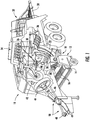
- FIGS. 1 and 2 illustrate differing views of one embodiment of an agricultural baler 10 in accordance with aspects of the present subject matter.
- FIG. 1 illustrates a perspective, partially cut-away view of one embodiment of an agricultural baler 10.
- FIG. 2 illustrates a schematic, internal view of the baler components that allow for the two-stages of crop compression within the baler 10.
- the baler 10 is a configured as a rectangular baler.
- the baler 10 may have any other suitable baler configuration.
- the baler 10 is configured to operate using a two-stage feeding system for intaking crop material and forming a bale therefrom.
- crop material is lifted from windrows into the baler 10 using a pickup unit 12.
- the pickup unit 12 includes a rotating pickup roll 14 with tines 16 which move the crop rearward toward a packer unit 18.
- An optional pair of stub augers (one of which is shown, but not numbered) is positioned above the pickup roll 14 to move the crop material laterally inward.
- the packer unit 18 includes packer tines 20 which push the crop into an inlet 21 ( FIG. 2 ) of a pre-compression chamber 22 to form a wad or charge of crop material.
- the packer tines 20 intertwine the crop together and pack the crop within the pre-compression chamber 22, with the pre-compression chamber 22 and the packer tines 20 generally functioning as the first stage of crop compression within the baler 10.
- a stuffer assembly 24 moves the charge of crop material through an outlet 23 ( FIG. 2 ) of the pre-compression chamber 22 to a main baling chamber 26 of the baler 10.
- the stuffer assembly 24 includes stuffer forks 28 which thrust the bale charge 80 directly in front of a plunger 30, which reciprocates back and forth relative to the baling chamber 26 to compress the charge of crop material 80 into a bale 82.
- the stuffer forks 28 are returned to their original stationary state after the bale charge 80 has been moved into the baling chamber 26.
- the plunger 30 compresses the charges of crop material to form a bale 82 and, at the same time, gradually advances the bale 82 towards an outlet 32 of the baling chamber 26.
- the baling chamber 26 and the plunger 30 generally function as the second stage if crop compression within the baler 10.
- the stuffer forks 28 of the stuffer assembly 26 may generally be configured to be actuated relative to the pre-compression chamber 22 using any suitable actuation means known in the art.
- the stuffer assembly 26 includes a first stuffer actuator 52 (e.g., a hydraulic cylinder or motor) coupled to the stuffer forks 28 and a second stuffer actuator 54 (e.g., a hydraulic cylinder or motor) coupled to the first stuffer actuator 52 via a lever 56.
- the stuffer forks 28 may be moved or actuated relative to the pre-compression chamber 22 to allow a charge of crop material to be formed therein and to also permit the charge of crop material to be pushed upwardly into the main baling chamber 26.
- the stuffer forks 28 are shown in FIG. 2 at a loading position 58 (indicated by the solid lines) at which the stuffer forks 28 essentially cover or close the outlet 23 of the pre-compression chamber 22, thereby allowing crop material entering the chamber 22 via the chamber inlet 21 to be compressed therein.
- the first stuffer actuator 52 may be initially retracted to move the stuffer forks 28 away from the chamber outlet 23 (e.g., in direction A), which then allows the first stuffer actuator 52 (and, thus, the stuffer forks 28 coupled thereto) to be pivoted downwardly (e.g., in pivot direction B) via retraction of the second stuffer actuator 54.
- the first stuffer actuator 52 can then be extended to actuate the stuffer forks 28 outwardly again towards the pre-compression chamber 22 (e.g., in direction C) to the charging position 60 (indicated by the dashed lines).
- the second stuffer actuator 54 can be extended to pivot the stuffer forks 28 upwardly (e.g., in pivot direction D), thereby allowing the stuffer forks 28 to sweep upwardly along a curved path following the curved shape of the pre-compression chamber 22 to push the charge of crop material through the chamber outlet 23 and into the baling chamber 26.
- the process can be repeated to allow a new charge of material to be compressed within the pre-compression chamber 22 and subsequently pushed into the main baling chamber 26 via actuation of the stuffer forks 28.
- the plunger 30 may be configured to be actuated relative to the baling chamber 26 using any suitable reciprocation or actuation means known in the art.
- the plunger 30 is connected via a crank arm 40 to a gear box 42.
- the gear box 42 is driven by a flywheel 44, which, in turn, is connected via a drive shaft 46 with a power take-off (PTO) coupler 48.
- the PTO coupler 48 is detachably connected with the PTO spline at the rear of the associated traction unit, such as a tractor (not shown).
- the PTO coupler 48, the drive shaft 46, and the flywheel 44 collectively define a portion of a driveline 50, which provides rotative power to the gearbox 42.
- the flywheel 44 has a sufficient mass to carry the plunger 30 through a compression stroke as power is applied to the drive shaft 46 by the traction unit (not shown).
- knotters 34 can be actuated which wrap and tie twine around the bale while it is still in the baling chamber 26. Needles 36 ( FIG. 1 ) are used to bring the lower twine up to the knotters 34 and the tying process takes place. The twine is cut and the formed bale is ejected from a discharge chute 38 ( FIG. 1 ) of the baler as a new bale is being formed within the baling chamber 26.
- a sensor assembly (indicated by dashed lines 102 in FIG. 2 ) may be provided in operative association with the pre-compression chamber 22 for sensing or detecting one or more parameters associated with the bale charge 80 being formed therein.
- the sensor assembly 102 may, in one embodiment, correspond to a microwave-based sensor assembly configured to transmit microwave signals through each bale charge 80 being formed within the pre-compression chamber 22 (or through a wall(s) of the chamber 22 itself).
- the detected properties of the microwave signals transmitted through each bale charge 80 may then be used at least in part to estimate or infer one or more parameters associated with the charge of crop material located within the pre-compression chamber 22, such as the extent to which the pre-compression chamber 22 is filled with crop material forming the bale charge 82 (i.e., the "filling degree") and/or one or more properties of the bale charge 80 (e.g., the moisture content and/or the density of the bale charge 80).
- the sensor assembly 102 is generally located within or adjacent to the pre-compression-chamber 22, such as by mounting components of the sensor assembly 102 to a wall(s) of the pre-compression chamber 22. As a result, the sensor assembly 102 may be used to detect parameters associated with the bale charge 80 being formed within the chamber 22. However, in other embodiments, the sensor assembly 102 may be positioned at any other suitable location within the baler 10 and/or may be mounted or coupled to any other suitable component of the baler 10 that allows the sensor assembly 102 to generally function as described herein.
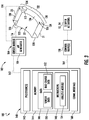
- FIG. 3 a schematic view of one embodiment of a system 100 for monitoring or determining one or more parameters associated with a charge of crop material or "bale charge" formed within a pre-compression chamber of an agricultural baler is illustrated in accordance with aspects of the present subject matter.
- the system 100 will generally be described herein with reference to baler 10 described above with reference to FIGS. 1 and 2 .
- the disclosed system 100 may generally be utilized with any baler have any suitable baler configuration to monitor one or more bale properties of a bale formed therein.
- the system 100 may include a microwave-based sensor assembly 102 configured to both generate microwave signals for transmission through a bale charge located within a pre-compression chamber of an agricultural baler (e.g., pre-compression chamber 22 of FIGS. 1 and 2 ) and subsequently receive or detect the microwave signals following transmission through the bale charge.
- the sensor assembly 102 includes a sensor module 104 having a microwave generator 106 associated therewith for generating microwave output signals.
- the microwave generator 106 may be configured to generate microwave signals at one or more frequencies for transmission through a charge of crop material location within the pre-compression chamber 22.
- the sensor module 104 may also include further components for processing and/or analyzing the microwave signals generated by the microwave generator 106 and/or the signals detected by or received back at the sensor module 104.
- the sensor module 104 may include a power divider, a directional coupler, and/or any other suitable components typically included within a radio-frequency (RF) box.
- RF radio-frequency
- the sensor assembly 102 includes both a first antenna 110 (hereinafter referred to as the "transmitter antenna”) and a second antenna 112 (hereinafter referred as the “receiver antenna”) communicatively coupled to the sensor module 104 (e.g., via communicative links 114, 116), with the transmitter antenna 110 being configured to transmit the microwave signals generated by the microwave generator 106 through the current bale charge located within the pre-compression chamber 22 and the receiver antenna 112 being configured to receive the microwave signals transmitted through the bale charge by the transmitter antenna 110.
- the sensor assembly 102 only includes a single pair of antennas 110, 112 for transmitting and receiving microwave signals.
- the sensor assembly 102 may include any other suitable number of antenna pairs for transmitting and receiving microwave signals, such as two or more antenna pairs.
- the sensor assembly 102 may include various pairs of antennas 110, 112 spaced apart along the length of the pre-compression chamber 22.
- the transmitter antennas 110 of the antenna pairs may be configured to be communicatively coupled to a common microwave generator (e.g., the microwave generator 106 shown in FIG. 3 ) or to respective microwave generators forming part of the sensor module 104 (or of respective sensor modules).
- the transmitter and receiver antennas 110, 112 are configured to be positioned along opposite sides of the bale charge being formed within the baler 10, thereby allowing microwave signals to be transmitted from one side of the bale charge and received on the other side of the bale charge.
- the transmitter and receiver antennas 110, 112 may be positioned along opposite sides of the pre-compression chamber 22 such that microwave signals can be transmitted through the bale charge being formed therein.
- the transmitter antenna 110 is coupled or positioned relative to or otherwise provided in operative association with a first sidewall 120 defining a first side 122 of the pre-compression chamber, while the receiver antenna 112 is coupled or positioned relative to or otherwise provided in operative association with an opposed second sidewall 124 defining an opposite, second side 126 of the pre-compression chamber 22.
- the transmitter antenna 110 may be used to transmit microwave signals from the first side 122 of the pre-compression chamber 22 through the bale charge for receipt by the receiver antenna 112 at the opposed second side 126 of the pre-compression chamber 22.
- the microwave signals may be transmitted through the entire lateral width of the bale charge (e.g., as indicated by width 128 in FIG. 3 ).
- the transmitter and receiver antennas 110, 112 may be configured to be positioned relative to the pre-compression chamber 22 so as to be located closer to the chamber outlet 23 than the chamber inlet 21.
- the pre-compression chamber 22 may include a lower region 130, a central region 132, and an upper region 134, with the lower region 132 extending along the length of the pre-compression chamber 22 from the chamber inlet 21 to the central region 132 and the upper region 134 extending along the length of the pre-compression chamber 22 from the central region 132 to the chamber outlet 23.
- the central region 132 may be defined across a central portion of the length of the pre-compression chamber 22 centered about a centerpoint 136 of the arc length of the chamber 22.
- the central region 132 may, for example, corresponds to a centrally located one-third of the length of the pre-compression chamber 22, while the lower and upper regions 130, 134 correspond to the remaining lower and upper one-thirds, respectively, of the length of the pre-compression chamber 22.
- the transmitter and receiver antennas 110, 112 are positioned within the upper region 134 of the pre-compression chamber 22 adjacent to the chamber outlet 23.
- the microwave signals transmitted and received by the antennas 110, 112 may be used, for example, to determine the filling degree of the upper region 134 of the pre-compression chamber 22 (i.e., the extent to which the upper region 134 is filled with crop material forming the current bale charge), which may provide an indication of the overall filling degree of the pre-compression chamber 22.
- the transmitter and receiver antennas 110, 112 may be disposed at any other suitable location relative to the pre-compression chamber 22 that allows the antennas 110, 112 to generally function as described herein.
- the antennas 110, 112 may be positioned along the top and bottom sides of the pre-compression chamber 22 such that microwave signals are transmitted through the current bale charge along its height.
- the antennas 110, 112 may be installed relative to the pre-compression chamber 22 at various different locations along its length.
- the system 100 may also include one or more processor-based or computing devices for receiving and subsequently processing the microwave-based data generated by the sensor assembly 102.
- the system 100 includes a controller 140 communicatively coupled to one or more components of the sensor assembly 102 (e.g., the sensor module 104) for receiving microwave-based data from the sensor assembly 102 associated with the microwave signals transmitted through the bale charge located within the pre-compression chamber 22 and subsequently detected by the receiver transmitter 112.
- the controller 140 may be configured to analyze the microwave-based data received from the sensor assembly 102 to determine one or more wave-related properties of the microwave signals received by the receiver transmitter 112, such as the wave attenuation and the phase angle of the microwave signals transmitted through a charge of crop material and received at the receiver transmitter 112. As will be described below, by determining such wave-related properties for the microwave signals transmitted through a charge of crop material, the controller 140 may be configured to determine or estimate one or more properties associated with the bale charge, such as the filling degree of the bale charge within the pre-compression chamber and/or one or more bale charge properties (e.g., moisture content and/or density).
- bale charge such as the filling degree of the bale charge within the pre-compression chamber and/or one or more bale charge properties (e.g., moisture content and/or density).
- the controller 140 may correspond to any suitable processor-based device(s), such as a computing device or any combination of computing devices.
- the controller 140 may generally include one or more processor(s) 142 and associated memory devices 144 configured to perform a variety of computer-implemented functions (e.g., performing the methods, steps, algorithms, calculations and the like disclosed herein).
- processor refers not only to integrated circuits referred to in the art as being included in a computer, but also refers to a controller, a microcontroller, a microcomputer, a programmable logic controller (PLC), an application specific integrated circuit, and other programmable circuits.
- PLC programmable logic controller
- the memory 144 may generally comprise memory element(s) including, but not limited to, computer readable medium (e.g., random access memory (RAM)), computer readable non-volatile medium (e.g., a flash memory), a floppy disk, a compact disc-read only memory (CD-ROM), a magneto-optical disk (MOD), a digital versatile disc (DVD) and/or other suitable memory elements.
- RAM random access memory
- RAM computer readable non-volatile medium
- CD-ROM compact disc-read only memory
- MOD magneto-optical disk
- DVD digital versatile disc
- Such memory 144 may generally be configured to store information accessible to the processor(s) 142, including data 146 that can be retrieved, manipulated, created and/or stored by the processor(s) 142 and instructions 148 that can be executed by the processor(s) 142.
- the data 146 may be stored in one or more databases.
- the memory 144 may include a sensor database 150 for storing data received from one or more sensors of the disclosed system 100.
- the microwave-based data received from the microwave sensor assembly 102 may be stored within the sensor database 150.
- suitable data derived from the microwave-based data may also be stored within the sensor database 150.
- data associated with any wave-related properties of the microwave signals received by the receiver transmitter 112 may be stored within the sensor database 150, such as by storing the wave attenuation and the phase angle of the microwave signals transmitted through each bale charge within the sensor database 150
- the memory 144 may include a bale charge database 152 for storing information related to one or more parameters associated with each bale charge being analyzed using the disclosure system 100. For instance, as indicated above, by analyzing the wave-related properties for the microwave signals transmitted through a bale charge located within the pre-compression chamber 22, the extent to which the pre-compression chamber 22 is filled with crop material (i.e., the "filling degree" of the chamber 22) may be estimated or inferred.
- the wave-related properties for the microwave signals transmitted through each bale charge may also be used to determine the dielectric properties of the associated bale charge (e.g., the real and imaginary parts of the dielectric constant), which can then be used to estimate or infer one or more other properties for the bale charge, such as the moisture content of the bale charge and/or the density of the bale charge.
- the various parameters determined in association with each bale charge may be stored within the bale charge database 152.
- the instructions 148 stored within the memory 144 of the controller 140 may be executed by the processor(s) 142 to implement a data analysis module 154.
- the data analysis module 154 may be configured to analyze the data received from any sensors of the disclosed system 100.
- the data analysis module 154 may be configured to analyze the microwave-based data received from the microwave sensor assembly 102 to determine one or more wave-related properties of the microwave signals transmitted through each bale charge and subsequently received by the receiver antenna 112.
- the data analysis module 154 may be configured to compare the amplitude of the microwave signal received at the receiver antenna 112 to the original amplitude of the microwave signal transmitted from the transmitter antenna 110 to determine the reduction in amplitude of the signal as it was transmitted through the bale charge (i.e., the wave attenuation).
- the data analysis module 154 may be configured to analyze the microwave-based data to determine the phase angle of the microwave signal received at the receiver antenna 112 (e.g.., using known signal analysis techniques).
- the system 100 may be used to transmit microwave signals through each bale charge being analyzed at two or more different frequencies.
- the data analysis module 154 may, for example, be configured to calculate the wave attenuation and phase angle associated with the microwave signals transmitted through the bale charge at each frequency.
- the data analysis module 154 may also be configured to determine one or more parameters associated with each bale charge being analyzed. Specifically, in several embodiments, the data analysis module 154 may be configured to determine such parameters based on the wave-related properties of the microwave signals transmitted through the bale charge, such as the wave attenuation and phase angle at each frequency. For instance, the wave attenuation of the microwave signals transmitted through each bale charge may be analyzed to estimate or infer the filling degree of the pre-compression chamber 22. Specifically, as the portion of the pre-compression chamber 22 through which the microwave signals are being transmitted fills with crop material, the attenuation of the microwave signals will increase.
- the degree to which the surrounding portion of the pre-compression chamber 22 is filled with crop material can be determined. For instance, a look-up table or similar relationship may be established that correlates the wave attenuation with a fill percentage associated with the filling degree of the pre-compression chamber 22, with the fill percentage increasing with increases in the wave attenuation.
- a wave attenuation of a given amount would be expected when the filling degree of the surrounding portion of the pre-compression chamber 22 is 25% full, while a wave attenuation of a larger amount would be expected when the filling degree of the surrounding portion of the pre-compression chamber 22 is 75% full.
- the positioning of the antennas 110, 112 may allow the data analysis module 154 to directly determine the filling degree of the adjacent portion of the pre-compression chamber 22, such as the filling degree of the upper region 134 of the pre-compression chamber 22.
- the data analysis module 154 may also be configured to estimate or infer the overall filling degree or fullness of the entire pre-compression chamber 22.
- the lower and central regions 130, 132 of the pre-compression chamber 22 tend to fill-up first with crop material, with the upper region 134 of the pre-compression chamber 22 typically being the last portion of the pre-compression chamber 22 to fill with crop material.
- a given threshold associated with a full or substantially filled chamber e.g., as determined based on the microwave signals transmitted and received by the antennas 110, 112
- the upper region 134 of the pre-compression chamber 22 may be determined to be full or to otherwise exhibit a maximum filling degree when the wave attenuation of the microwave signals transmitted through the bale charge is equal to or exceeds a predetermined maximum attenuation threshold.
- the data analysis module 154 determines that the wave attenuation is equal to or exceeds the predetermined threshold (and, thus, the upper region 134 of the pre-compression chamber 22 is full of crop material)
- the filling degree or fullness of each respective region 130, 132, 134 of the pre-compression chamber 22 may be determined. For instance, as will be described below with reference to FIG. 4 , multiple pairs of antennas 110, 112 may be spaced apart along the length of the pre-compression chamber 22 to allow the filling degree or fullness of the chamber 22 to be determined at various different locations.
- the data analysis module 154 may also be configured to determine one or more bale charge properties associated with each bale charge being analyzed based on the wave-related properties of the microwave signals transmitted through the bale charge. Specifically, in several embodiments, the data analysis module 154 may be configured to calculate the dielectric properties associated with the bale charge being analyzed based on both the phase angle displacement of the microwave signals transmitted through the bale charge at two or more different frequencies and the wave attenuation of the microwave signals. Such dielectric properties may then be used to estimate or infer one or more additional properties associated with the bale charge, such as the moisture content or the density of the bale charge.
- the data analysis module 154 may, instead, form part of and/or may be configured to be executed by a separate processor-based device, such as a separate computing device.
- the data analysis module 154 (as included within or executed by the separate processor-based device) may be communicatively coupled to the controller 140 such that data may be transmitted between such devices, such as data received and/or generated by the data analysis module 154.
- the controller 140 may be configured to actively control the operation of one or more components of the disclosed system 100.
- the controller 140 may be communicatively coupled to one or more control valves 158 for regulating the supply of hydraulic fluid to the actuators 52, 54 of the stuffer assembly 24.
- the controller 140 may be configured to actively control the operation of the stuffer assembly 24, thereby allowing the controller 140 to regulate when the current bale charge being formed within the pre-compression 22 is delivered to the main baling chamber 26.
- the controller 140 may be configured to actively monitor the filling degree of a given region of the pre-compression chamber 22 (e.g., the upper region 134) and/or the overall filling degree of the of the pre-compression chamber 22 to determine when such filling degree exceed a given filling degree or fullness threshold. Once it is determined that the monitored filling degree is equal to or exceeds the desired threshold, the stuffer forks 28 may be actuated (via control of the operation of the stuffer actuators 52, 54) to push the bale charge from the pre-compression chamber 22 and into the main baling chamber 26.
- the stuffer forks 28 may be actuated (via control of the operation of the stuffer actuators 52, 54) to push the bale charge from the pre-compression chamber 22 and into the main baling chamber 26.
- the controller 140 may also be configured to actively control the operation of the microwave generator 106 of the sensor assembly 102.
- the controller 140 may be configured to control the operation of the microwave generator 106 such that microwave signals of a given frequency (or microwave signals at differing frequencies) are transmitted through each bale charge being analyzed.
- the controller 140 may be configured to control the operation of the microwave generator 106 such that a first microwave signal is initially transmitted through the current bale charge at a first frequency (e.g., 2GHz) and then a second microwave signal is transmitted through the bale charge at a second frequency (e.g., 4GHz) that differs from the first frequency.
- a first frequency e.g., 2GHz
- a second microwave signal is transmitted through the bale charge at a second frequency (e.g., 4GHz) that differs from the first frequency.
- the controller 140 may also include a communications interface 160 to provide a means for the controller 140 to communicate with any of the various other system components described herein.
- a communications interface 160 to provide a means for the controller 140 to communicate with any of the various other system components described herein.
- one or more respective communicative links or interfaces 162 e.g., one or more data buses
- one or more respective communicative links or interfaces 164 may be provided between the communications interface 160 and the control valve(s) 158 to allow control signals to be transmitted from the controller 140 to the valve(s) 158 for controlling the operation of the stuffer actuators 52, 54.
- the dielectric properties of the bale charge may be determined.
- the real part of the dielectric constant may be determined as a function of the differential or displacement of the phase angles of the microwave signals at differing frequencies. For instance, both the phase angle differential between two microwave signals transmitted at differing frequencies through a bale charge and the real part of the dielectric constant of such bale charge can be expressed as a function of the velocity of the wave through the bale charge.
- ⁇ ⁇ corresponds to the phase angle displacement or differential between the phase angles ( ⁇ p) detected for a microwave signal transmitted through a bale charge at a first frequency ( f 1 ) and a microwave signal transmitted through the bale charge at a second frequency ( f 2 )
- ⁇ f corresponds to the differential or difference between the first frequency ( f 1 ) and the second frequency ( f 2 )
- d corresponds to the distance between the microwave transmitter 110 and the microwave receiver 112 (e.g., the width 128 of the bale charge)
- v corresponds to the velocity of the microwave signals through the bale charge
- c corresponds to the speed of light
- ⁇ ' corresponds to the real part of the dielectric constant associated with the bale charge.
- the real part of the dielectric constant associated with the bale charge can be calculated.
- the real part of the dielectric constant can then be used to calculate the imaginary part of the dielectric constant associated with the bale charge based on the determined wave attenuation for one of the microwave signals.
- values for both the moisture content of the bale charge and the density of the bale charge may be calculated.
- a direct correlation e.g., a quadratic relationship
- a direct correlation e.g., a linear relationship
- the system controller 140 may calculate both a moisture content value and a density value for each bale charge being analyzed within the pre-compression chamber 22. Such moisture/density values may then be stored within the controller's memory 144 as described above (e.g., with the bale charge database 152).
- the correlation or relationship between the dielectric properties and the bale charge moisture content and between the dielectric properties and the bale charge density may be stored within the controller 140 in any suitable form that allows the controller 140 to calculate the corresponding moisture content and density values for the bale charge being analyzed.
- such correlations or relationships may be stored as mathematical formulas or expressions or may be stored as suitable look-up tables within the controller's memory 144.
- the relevant correlations or relationships may be established via routine experimentation. For instance, experimental trials may be conducted with various bale charges of known moisture content and density to establish the desired correlations or relationships between the dielectric properties and the bale charge moisture/density.
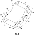
- FIG. 4 a partial, schematic view of another embodiment of the system 100 described above with reference to FIG. 3 is illustrated in accordance with aspects of the present subject matter, particularly illustrating an example sensor arrangement suitable for use within the disclosed system 100.
- FIG. 4 illustrates an embodiment of the system 100 that includes several pairs of transmitter/receiver antennas 110, 112 spaced apart from one another along the length of pre-compression chamber 22 between its inlet 21 and its outlet 23.
- a first pair of transmitter/receiver antennas 110A, 112A are positioned on opposed sides of the pre-compression chamber 22 so as to allow microwave signals to be transmitted through the crop material contained within the upper region 134 of the pre-compression chamber 22.
- second and third pairs of transmitter/receiver antennas 110B, 112B, 110C, 112C are positioned on opposed sides of the pre-compression chamber 22 so as to allow microwave signals to be transmitted through the crop material contained within the central and lower regions 132, 130 of the pre-compression chamber 22, respectively.
- the illustrated sensor arrangement may allow for the filling degree or fullness of each region 130, 132, 134 of the pre-compression chamber 22 to be determined, which, in turn, may allow for the overall filling degree or fullness of the pre-compression chamber 22 to be estimated or inferred with a greater degree of confidence.
- the illustrated sensor arrangement may also allow for various datapoints to be collected along the length of the pre-compression chamber 22 that are related to the moisture content and/or the density of the bale charge being formed within the chamber 22. Such measurements may then, for example, be averaged to determine an average moisture content and/or average density of the current bale charge located within the pre-compression chamber 22.
- any other suitable sensor arrangement may be utilized within the disclosed system 100 in accordance with aspects of the present subject matter, including any combination of the pairs of antennas 110, 112.
- the system 100 may include only the upper and central pairs of antennas 110A, 112A, 110B, 112B, or only the upper and lower pairs of antennas 110A, 112A, 110C, 112C, or only the central and lower pairs of antennas 110B, 112B, 110C, 112C.
- the system 100 may include only the central pair of antennas 110B, 112B or only the lower pair of antennas 110C, 112C.
- FIG. 5 another embodiment of the system 100 described above with reference to FIG. 3 is illustrated in accordance with aspects of the present subject matter.
- the system includes many of the same or similar components as that described above with reference to FIG. 3 , such as the microwave generator 106 and the controller 140.
- the system 100 shown in FIG. 5 unlike the embodiment of the system 100 described above that includes a pair of antennas 110, 112 configured to transmit microwave signals though a bale charge located within the pre-compression chamber 22 and subsequently receive such signals as transmitted through the bale charge, the system 100 shown in FIG.
- the pre-compression chamber 22 may be configured to function as a resonant cavity and, thus, may allow an electromagnetic resonance to excited within the chamber 22 via transmission of the microwave signal(s), with the resulting resonant frequency and its quality factor differing depending on the extent to which the pre-compression chamber is filled with crop material (e.g., with the shifts being due to the dielectric properties of the crop material inside the chamber).
- the real and imaginary part of the dielectric constant can be determined and thus, for example, the filling degree of the pre-compression chamber may be estimated or determined.
- the resonant frequency shift associated with the electromagnetic resonance within the chamber 22 when excited by a microwave signal of a given input frequency may be measured by the transmitter probe 180, itself.
- the transmitter probe 180 may be configured to measure or detect the amount of power absorbed by the pre-compression chamber when exciting the electromagnetic resonance with the microwave signals, which is directly indicative of the resonant frequency shift and the quality factor within the pre-compression chamber.
- a secondary sensor probe 182 may be used to measure the resonant frequency at a different location along the pre-compression chamber (e.g., the opposed sidewall 124). The resonant frequency 182 measured by the secondary sensor probe 182 may then be used to determine the resonant frequency shift associated with the electromagnetic resonance within the chamber 22.
- the quality factor associated with the electromagnetic resonance within the chamber 22 may generally be determined as a function of the resonant frequency and the resonant width (e.g., the ratio of the resonant frequency to the resonant width), with the resonant width being defined as the full width at half maximum power (i.e., the width of the resonance at half the maximum value of the measured power).
- the "resonant cavity” technique may also be used to determine or estimate one or more properties of the current bale charge being formed within the pre-compression chamber 22. For instance, by determining the resonant frequency shift and the quality factor associated with the electromagnetic resonance excited within the chamber 22 via the transmission of microwave signals through or into a wall(s) of the chamber, the dielectric properties associated with the bale charge (e.g., the real and imaginary parts of the dielectric constant associated with the bale) may be determined or estimated. Such dielectric properties may allow one or more related bale charge properties to be calculated, such as the moisture content of the bale charge and/or the density of the bale charge.
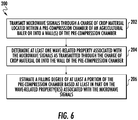
- FIG. 6 a flow diagram of one embodiment of a method 200 for determining one or more parameters associated with a bale charge located within a pre-compression chamber of an agricultural baler is illustrated in accordance with aspects of the present subject matter.
- the method 200 will be described herein with reference to the baler 10 and the embodiments of the system 100 described above with reference to FIGS. 1-5 .
- the disclosed method 200 may generally be implemented with any agricultural baler having any suitable baler configuration and/or any system having any suitable system configuration.
- FIG. 6 depicts steps performed in a particular order for purposes of illustration and discussion, the methods discussed herein are not limited to any particular order or arrangement.
- steps of the methods disclosed herein can be omitted, rearranged, combined, and/or adapted in various ways without deviating from the scope of the present disclosure.
- the method 200 includes transmitting microwave signals through a charge of crop material located within a pre-compression chamber of an agricultural baler or into a wall(s) of the pre-compression chamber.
- a microwave sensor assembly 102 may be used to generate microwave signals for transmission through a bale charge to be analyzed, such as the current bale charge being formed within the pre-compression chamber 22 of the baler 10.
- the generated microwave signals may be transmitted through the bale charge via a transmitter antenna 110 of the sensor assembly 102 and subsequently received via a receiver antenna 112 of the sensor assembly 102.
- the generated microwave signals may be transmitted into a wall(s) of the pre-compression chamber 22 to excite an electromagnetic resonance within the chamber 22.
- the method 200 includes determining at least one wave-related property associated with the microwave signals as transmitted through the charge of crop material or into the wall of the pre-compression chamber.
- the controller 140 may be configured to analyze the microwave-based data received from the sensor assembly 102 to determine one or more wave-related properties associated with the microwave signals detected by the receiver antenna 112, such as the phase angle and wave attenuation of each signal transmitted through the bale charge and subsequently received by the receiver antenna 112 of the sensor assembly 104.
- the controller 140 may be configured to determine one or more wave-related properties associated within the transmission of the microwave signals through the pre-compression chamber wall(s), such as the resonant frequency shift and the quality factor of the chamber 22 following excitation thereof.
- the method 200 includes estimating a filling degree of at least a portion of the pre-compression chamber based at least in part on the at least one wave-related property associated with the microwave signals.
- the controller 140 may be configured to determine the filling degree of a given region of the pre-compression chamber 22 and/or the entire pre-compression chamber 22. Such a determination may, for instance, be made based on the wave attenuation of the microwave signals transmitted though the bale charge located within the pre-compression chamber or the resonant frequency shift within the pre-compression chamber 22 following excitation thereof.
- a look-up table or other relationship may be established that correlates the wave attenuation of the microwave signals (or the resonant frequency shift and/or the quality factor) to the filling degree of the pre-compression chamber 22.
- the controller 140 may determine when the pre-compression chamber 22 is full or substantially full (e.g., by comparing the determined filling degree to a predetermined filling degree or fullness threshold).
- the controller 140 may actively control the operation of the stuffer assembly 24 to push the current bale charge from the pre-compression chamber 22 and into the main baling chamber 26. However, if it is, instead, determined that the current filling degree of the bale charge is less than the predetermined filling degree threshold (thereby indicating that the pre-compression chamber 22 is not full or substantially full), the controller 140 may delay actuating the stuffer assembly 24 to allow additional crop material to be supplied into pre-compression chamber 22.
- the steps of the method 200 are performed by the controller 140 upon loading and executing software code or instructions which are tangibly stored on a tangible computer readable medium, such as on a magnetic medium, e.g., a computer hard drive, an optical medium, e.g., an optical disc, solid-state memory, e.g., flash memory, or other storage media known in the art.
- a tangible computer readable medium such as on a magnetic medium, e.g., a computer hard drive, an optical medium, e.g., an optical disc, solid-state memory, e.g., flash memory, or other storage media known in the art.
- any of the functionality performed by the controller 140 described herein, such as the method 200 is implemented in software code or instructions which are tangibly stored on a tangible computer readable medium.
- the controller 140 loads the software code or instructions via a direct interface with the computer readable medium or via a wired and/or wireless network. Upon loading and executing such software code or instructions by the controller 140, the controller 140
- software code or “code” used herein refers to any instructions or set of instructions that influence the operation of a computer or controller. They may exist in a computer-executable form, such as machine code, which is the set of instructions and data directly executed by a computer's central processing unit or by a controller, a human-understandable form, such as source code, which may be compiled in order to be executed by a computer's central processing unit or by a controller, or an intermediate form, such as object code, which is produced by a compiler.
- the term "software code” or “code” also includes any human-understandable computer instructions or set of instructions, e.g., a script, that may be executed on the fly with the aid of an interpreter executed by a computer's central processing unit or by a controller.
Landscapes
- Life Sciences & Earth Sciences (AREA)
- Environmental Sciences (AREA)
- Physics & Mathematics (AREA)
- Electromagnetism (AREA)
- Health & Medical Sciences (AREA)
- Chemical & Material Sciences (AREA)
- Analytical Chemistry (AREA)
- Biochemistry (AREA)
- General Health & Medical Sciences (AREA)
- General Physics & Mathematics (AREA)
- Immunology (AREA)
- Pathology (AREA)
- Auxiliary Devices For And Details Of Packaging Control (AREA)
- Management, Administration, Business Operations System, And Electronic Commerce (AREA)
Abstract
Description
- The present subject matter relates generally to agricultural balers, and, more particularly, to systems and methods for estimating or determining one or more parameters associated with a charge of crop material or "bale charge" located within a pre-compression chamber of an agricultural baler, such as by estimating or determining the extent to which the pre-compression chamber is filled with the crop material forming the bale charge and/or by estimating or determining one or more properties of the bale charge (e.g., moisture content and/or density).
- Agricultural balers are used to consolidate and package crop material to facilitate storage and handling of the crop material for later use. In the case of hay, a mower-conditioner is typically used to cut and condition the crop material for windrow drying in the sun. In the case of straw, an agricultural combine discharges non-grain crop material from the rear of the combine (such as wheat or oat straw), which is subsequently picked up by the baler. The cut crop material is typically raked and dried, and a baler, such as a large square baler or round baler, straddles the windrows and travels along the windrows to pick up the crop material and form it into bales. For instance, on a large square baler, a pickup unit at the front of the baler gathers the cut and windrowed crop material from the ground. A packer unit is used to move the crop material from the pickup unit to a duct or pre-compression chamber. For example, the packer unit is typically configured to form a wad or charge of crop material within the pre-compression chamber, which is then transferred to a main baling chamber. Within the main baling chamber, a plunger compresses the charges of crop material to form a bale and, at the same time, gradually advances the bale toward the outlet of the baling chamber.
- Currently, many agricultural balers include mechanical fin sensors located at the inlet of the pre-compression chamber to allow the degree of fullness (or "filling degree") of the pre-compression chamber to be estimated. However, such mechanical fin sensors only provide an indication of the filling degree at the inlet of the pre-compression chamber. Unfortunately, given the manner in which crop material is packed or compressed into the pre-compression chamber, instances often arise in which the area around the chamber inlet is quite full with crop material, but the portions of the pre-compression chamber that are further away from the inlet (e.g., at or adjacent to the outlet) have a significantly lower filling degree. In such instances, the mechanical fin sensors will indicate that the pre-compression chamber is completely full, thereby leading to the existing charge of crop material being transferred to main baling chamber. Such non-uniformly filled bale charges result in bales being formed within the main baling chamber that are not uniform in density and/or that do not exhibit the desired shape. Moreover, since the mechanical fin sensors correspond to contact-based sensors, such conventional sensors tend to modify the flow of crop material within the pre-compression chamber, which can lead to non-uniform filling of the chamber.
- Accordingly, improved systems and related methods for determining one or more parameters associated with a charge of crop material located within a pre-compression chamber of an agricultural baler would be welcomed in the technology.
- Aspects and advantages of the invention will be set forth in part in the following description, or may be obvious from the description, or may be learned through practice of the invention.
- In one aspect, the present subject matter is directed to a method for determining parameters associated with bale charges formed within agricultural balers. The method includes transmitting microwave signals through a charge of crop material located within a pre-compression chamber of an agricultural baler or into a wall of the pre-compression chamber. Additionally, the method includes determining, with one or more computing devices, at least one wave-related property associated with the microwave signals as transmitted through the charge of crop material or into the wall of the pre-compression chamber, and estimating, with the one or more computing devices, a filling degree of at least a portion of the pre-compression chamber based at least in part on the at least one wave-related property associated with the microwave signals.
- In another aspect, the present subject matter is directed to a system for determining parameters associated with bale charges formed within an agricultural bale. The system includes a pre-compression chamber of the agricultural baler, and a transmitter configured to transmit microwave signals through a charge crop material located within the pre-compression chamber or into a wall of the pre-compression chamber. In addition, the system includes a controller configured to determine at least one wave-related property associated with the microwave signals as transmitted through the charge of crop material or into the wall of the pre-compression chamber, and estimate a filling degree of at least a portion of the pre-compression chamber based at least in part on the at least one wave-related property associated with the microwave signals.
- These and other features, aspects and advantages of the present invention will become better understood with reference to the following description and appended claims. The accompanying drawings, which are incorporated in and constitute a part of this specification, illustrate embodiments of the invention and, together with the description, serve to explain the principles of the invention.
- A full and enabling disclosure of the present invention, including the best mode thereof, directed to one of ordinary skill in the art, is set forth in the specification, which makes reference to the appended figures, in which:
-
FIG. 1 illustrates a perspective, partially cut-away view of one embodiment of an agricultural baler in accordance with aspects of the present subject matter; -
FIG. 2 illustrates a schematic, internal view of a pre-compression chamber and a main baling chamber of the baler shown inFIG. 1 , particularly illustrating a microwave sensor assembly provided in operative association with the pre-compression chamber of the baler in accordance with aspects of the present subject matter; -
FIG. 3 illustrates a schematic view of one embodiment of a system for determining one or more parameters of a charge of crop material formed within a pre-compression chamber of an agricultural baler in accordance with aspects of the present subject matter; -
FIG. 4 illustrates a schematic view of another embodiment of a sensor arrangement suitable for use within one embodiment of the system shown inFIG. 3 in accordance with aspects of the present subject matter; -
FIG. 5 illustrates a schematic view of a further embodiment of a sensor arrangement suitable for use within one embodiment of the system shown inFIG. 3 in accordance with aspects of the present subject matter; and -
FIG. 6 illustrates a flow diagram of one embodiment of a method for determining one or more parameters of a charge of crop material formed within a pre-compression chamber of an agricultural baler in accordance with aspects of the present subject matter. - Reference now will be made in detail to embodiments of the invention, one or more examples of which are illustrated in the drawings. Each example is provided by way of explanation of the invention, not limitation of the invention. In fact, it will be apparent to those skilled in the art that various modifications and variations can be made in the present invention without departing from the scope or spirit of the invention. For instance, features illustrated or described as part of one embodiment can be used with another embodiment to yield a still further embodiment. Thus, it is intended that the present invention covers such modifications and variations as come within the scope of the appended claims and their equivalents.
- In general, the present subject matter is directed to systems and methods for determining parameters associated with charges of crop material or "bale charges" formed within an agricultural baler. Specifically, in several embodiments, the disclosed system and method utilizes a microwave-based sensor assembly to transmit microwave signals through a bale charge disposed within a pre-compression chamber of an agricultural baler. The microwave signals transmitted through the bale charge can then be detected (e.g., by a receiver antenna of the sensor assembly) to allow one or more wave-related properties of the microwave signals to be determined, such as the wave attenuation and/or the phase angle of the microwave signals following transmission through the bale charge. The wave-related properties may then be used to determine one or more parameters associated with the bale charge. Alternatively, a transmitter probe may be used to transmit microwave signals into a wall(s) of the pre-compression chamber to excite an electromagnetic resonance within the chamber. The transmitter probe (or a separate sensor probe) may then be used to determine one or more wave-related properties associated with the electromagnetic resonance (e.g., the resonant frequency of the chamber, a shift in the resonant frequency of the chamber, a quality factor variation, etc.)
- In several embodiments, the data collected in association with the transmitted microwave signals may be used to determine or estimate the extent to which the pre-compression chamber is filled with crop material (i.e., the "filling degree" of the pre-compression chamber). For instance, in one embodiment, the wave attenuation of the microwave signals transmitted through the charge of crop material located within the pre-compression chamber may be correlated to the filling degree of the pre-compression chamber. Thus, by determining the wave attenuation of the microwave signals, the filling degree of the pre-compression chamber may be estimated or inferred. This information may then be used to control related aspects of the baling process. For instance, when the determined filling degree is indicative of the pre-compression chamber being fully or substantially full, the operation of an associated stuffer assembly may be controlled to cause the bale charge formed within the pre-compression chamber to be pushed from the chamber into the main baling chamber of the baler to allow a bale to be formed therein.
- Moreover, the data collected in association with the transmitted microwave signals may also be used to determine or estimate one or more properties of the current bale charge being formed within the pre-compression chamber. For instance, by determining the phase angle of microwave signals transmitted through a given bale charge at two different frequencies, the phase angle differential or displacement between the two frequencies can be calculated, which may then be used to determine the dielectric properties associated with the bale charge (e.g., the real and imaginary parts of the dielectric constant associated with the bale). Similarly, by determining the resonant frequency shift and the quality factor of the cavity based on the excitation of the electromagnetic resonance, the dielectric properties associated with the bale charge (e.g., the real and imaginary parts of the dielectric constant associated with the bale) may be determined or estimated. Such dielectric properties may allow one or more related bale charge properties to be calculated, such as the moisture content of the bale charge and/or the density of the bale charge.
- Referring now to the drawings,
FIGS. 1 and2 illustrate differing views of one embodiment of anagricultural baler 10 in accordance with aspects of the present subject matter. Specifically,FIG. 1 illustrates a perspective, partially cut-away view of one embodiment of anagricultural baler 10. Additionally,FIG. 2 illustrates a schematic, internal view of the baler components that allow for the two-stages of crop compression within thebaler 10. In the illustrated embodiment, thebaler 10 is a configured as a rectangular baler. However, it should be appreciated that, in other embodiments, thebaler 10 may have any other suitable baler configuration. - As particularly shown in
FIG. 1 , thebaler 10 is configured to operate using a two-stage feeding system for intaking crop material and forming a bale therefrom. Specifically, crop material is lifted from windrows into thebaler 10 using apickup unit 12. In one embodiment, thepickup unit 12 includes a rotatingpickup roll 14 withtines 16 which move the crop rearward toward apacker unit 18. An optional pair of stub augers (one of which is shown, but not numbered) is positioned above thepickup roll 14 to move the crop material laterally inward. Additionally, thepacker unit 18 includespacker tines 20 which push the crop into an inlet 21 (FIG. 2 ) of apre-compression chamber 22 to form a wad or charge of crop material. Specifically, thepacker tines 20 intertwine the crop together and pack the crop within thepre-compression chamber 22, with thepre-compression chamber 22 and thepacker tines 20 generally functioning as the first stage of crop compression within thebaler 10. - Once a sufficient charge of crop material or "bale charge" 80 (
FIG. 2 ) has been formed within thepre-compression chamber 22, astuffer assembly 24 moves the charge of crop material through an outlet 23 (FIG. 2 ) of thepre-compression chamber 22 to amain baling chamber 26 of thebaler 10. As particularly shown inFIG. 2 , thestuffer assembly 24 includesstuffer forks 28 which thrust thebale charge 80 directly in front of aplunger 30, which reciprocates back and forth relative to the balingchamber 26 to compress the charge ofcrop material 80 into abale 82. Thestuffer forks 28 are returned to their original stationary state after thebale charge 80 has been moved into the balingchamber 26. Theplunger 30 compresses the charges of crop material to form abale 82 and, at the same time, gradually advances thebale 82 towards anoutlet 32 of the balingchamber 26. The balingchamber 26 and theplunger 30 generally function as the second stage if crop compression within thebaler 10. - It should be appreciated that the
stuffer forks 28 of thestuffer assembly 26 may generally be configured to be actuated relative to thepre-compression chamber 22 using any suitable actuation means known in the art. For instance, in the embodiment shown inFIG. 2 , thestuffer assembly 26 includes a first stuffer actuator 52 (e.g., a hydraulic cylinder or motor) coupled to thestuffer forks 28 and a second stuffer actuator 54 (e.g., a hydraulic cylinder or motor) coupled to thefirst stuffer actuator 52 via alever 56. In such an embodiment, by controlling the extension/retraction of thestuffer actuators stuffer forks 28 may be moved or actuated relative to thepre-compression chamber 22 to allow a charge of crop material to be formed therein and to also permit the charge of crop material to be pushed upwardly into themain baling chamber 26. - For instance, the
stuffer forks 28 are shown inFIG. 2 at a loading position 58 (indicated by the solid lines) at which thestuffer forks 28 essentially cover or close theoutlet 23 of thepre-compression chamber 22, thereby allowing crop material entering thechamber 22 via thechamber inlet 21 to be compressed therein. Once a sufficient charge of crop material has been compressed into thechamber 22, thefirst stuffer actuator 52 may be initially retracted to move thestuffer forks 28 away from the chamber outlet 23 (e.g., in direction A), which then allows the first stuffer actuator 52 (and, thus, thestuffer forks 28 coupled thereto) to be pivoted downwardly (e.g., in pivot direction B) via retraction of thesecond stuffer actuator 54. Once thestuffer forks 28 have been pivoted downwardly to their lowermost position, thefirst stuffer actuator 52 can then be extended to actuate thestuffer forks 28 outwardly again towards the pre-compression chamber 22 (e.g., in direction C) to the charging position 60 (indicated by the dashed lines). Thereafter, with thefirst stuffer actuator 52 maintained at the extended position, thesecond stuffer actuator 54 can be extended to pivot thestuffer forks 28 upwardly (e.g., in pivot direction D), thereby allowing thestuffer forks 28 to sweep upwardly along a curved path following the curved shape of thepre-compression chamber 22 to push the charge of crop material through thechamber outlet 23 and into the balingchamber 26. With thestuffer forks 28 back to theloading position 58, the process can be repeated to allow a new charge of material to be compressed within thepre-compression chamber 22 and subsequently pushed into themain baling chamber 26 via actuation of thestuffer forks 28. - It should also be appreciated that the
plunger 30 may be configured to be actuated relative to the balingchamber 26 using any suitable reciprocation or actuation means known in the art. For instance, in the embodiment shown inFIG. 1 , theplunger 30 is connected via acrank arm 40 to agear box 42. Thegear box 42 is driven by aflywheel 44, which, in turn, is connected via adrive shaft 46 with a power take-off (PTO)coupler 48. ThePTO coupler 48 is detachably connected with the PTO spline at the rear of the associated traction unit, such as a tractor (not shown). ThePTO coupler 48, thedrive shaft 46, and theflywheel 44 collectively define a portion of adriveline 50, which provides rotative power to thegearbox 42. Theflywheel 44 has a sufficient mass to carry theplunger 30 through a compression stroke as power is applied to thedrive shaft 46 by the traction unit (not shown). - When a formed
bale 82 reaches a predetermined size within the baling chamber 26 (e.g., as determined via a suitable measurement device, such as a star wheel), knotters 34 (FIG. 1 ) can be actuated which wrap and tie twine around the bale while it is still in the balingchamber 26. Needles 36 (FIG. 1 ) are used to bring the lower twine up to theknotters 34 and the tying process takes place. The twine is cut and the formed bale is ejected from a discharge chute 38 (FIG. 1 ) of the baler as a new bale is being formed within the balingchamber 26. - Additionally, as will be described in greater detail below, in several embodiments, a sensor assembly (indicated by dashed
lines 102 inFIG. 2 ) may be provided in operative association with thepre-compression chamber 22 for sensing or detecting one or more parameters associated with thebale charge 80 being formed therein. Specifically, in accordance with aspects of the present subject matter, thesensor assembly 102 may, in one embodiment, correspond to a microwave-based sensor assembly configured to transmit microwave signals through eachbale charge 80 being formed within the pre-compression chamber 22 (or through a wall(s) of thechamber 22 itself). The detected properties of the microwave signals transmitted through each bale charge 80 (or the wall(s) of the chamber 22) may then be used at least in part to estimate or infer one or more parameters associated with the charge of crop material located within thepre-compression chamber 22, such as the extent to which thepre-compression chamber 22 is filled with crop material forming the bale charge 82 (i.e., the "filling degree") and/or one or more properties of the bale charge 80 (e.g., the moisture content and/or the density of the bale charge 80). - As shown in
FIG. 2 , thesensor assembly 102 is generally located within or adjacent to the pre-compression-chamber 22, such as by mounting components of thesensor assembly 102 to a wall(s) of thepre-compression chamber 22. As a result, thesensor assembly 102 may be used to detect parameters associated with thebale charge 80 being formed within thechamber 22. However, in other embodiments, thesensor assembly 102 may be positioned at any other suitable location within thebaler 10 and/or may be mounted or coupled to any other suitable component of thebaler 10 that allows thesensor assembly 102 to generally function as described herein. - Referring now to
FIG. 3 , a schematic view of one embodiment of asystem 100 for monitoring or determining one or more parameters associated with a charge of crop material or "bale charge" formed within a pre-compression chamber of an agricultural baler is illustrated in accordance with aspects of the present subject matter. For purposes of description, thesystem 100 will generally be described herein with reference tobaler 10 described above with reference toFIGS. 1 and2 . However, it should be appreciated that the disclosedsystem 100 may generally be utilized with any baler have any suitable baler configuration to monitor one or more bale properties of a bale formed therein. - In several embodiments, the
system 100 may include a microwave-basedsensor assembly 102 configured to both generate microwave signals for transmission through a bale charge located within a pre-compression chamber of an agricultural baler (e.g.,pre-compression chamber 22 ofFIGS. 1 and2 ) and subsequently receive or detect the microwave signals following transmission through the bale charge. For instance, as shown inFIG. 3 , thesensor assembly 102 includes asensor module 104 having amicrowave generator 106 associated therewith for generating microwave output signals. Specifically, in accordance with aspects of the present subject matter, themicrowave generator 106 may be configured to generate microwave signals at one or more frequencies for transmission through a charge of crop material location within thepre-compression chamber 22. It should be appreciated that thesensor module 104 may also include further components for processing and/or analyzing the microwave signals generated by themicrowave generator 106 and/or the signals detected by or received back at thesensor module 104. For instance, in one embodiment, thesensor module 104 may include a power divider, a directional coupler, and/or any other suitable components typically included within a radio-frequency (RF) box. - In addition, the
sensor assembly 102 includes both a first antenna 110 (hereinafter referred to as the "transmitter antenna") and a second antenna 112 (hereinafter referred as the "receiver antenna") communicatively coupled to the sensor module 104 (e.g., viacommunicative links 114, 116), with thetransmitter antenna 110 being configured to transmit the microwave signals generated by themicrowave generator 106 through the current bale charge located within thepre-compression chamber 22 and thereceiver antenna 112 being configured to receive the microwave signals transmitted through the bale charge by thetransmitter antenna 110. In the illustrated embodiment, thesensor assembly 102 only includes a single pair ofantennas sensor assembly 102 may include any other suitable number of antenna pairs for transmitting and receiving microwave signals, such as two or more antenna pairs. For instance, as will be described below with reference toFIG. 4 , thesensor assembly 102 may include various pairs ofantennas pre-compression chamber 22. In such an embodiment, thetransmitter antennas 110 of the antenna pairs may be configured to be communicatively coupled to a common microwave generator (e.g., themicrowave generator 106 shown inFIG. 3 ) or to respective microwave generators forming part of the sensor module 104 (or of respective sensor modules). - In several embodiments, the transmitter and
receiver antennas baler 10, thereby allowing microwave signals to be transmitted from one side of the bale charge and received on the other side of the bale charge. Specifically, in one embodiment, the transmitter andreceiver antennas pre-compression chamber 22 such that microwave signals can be transmitted through the bale charge being formed therein. For instance, as shown in the illustrated embodiment, thetransmitter antenna 110 is coupled or positioned relative to or otherwise provided in operative association with afirst sidewall 120 defining afirst side 122 of the pre-compression chamber, while thereceiver antenna 112 is coupled or positioned relative to or otherwise provided in operative association with an opposedsecond sidewall 124 defining an opposite,second side 126 of thepre-compression chamber 22. In such an embodiment, as a bale charge is being formed within thepre-compression chamber 22, thetransmitter antenna 110 may be used to transmit microwave signals from thefirst side 122 of thepre-compression chamber 22 through the bale charge for receipt by thereceiver antenna 112 at the opposedsecond side 126 of thepre-compression chamber 22. As a result, the microwave signals may be transmitted through the entire lateral width of the bale charge (e.g., as indicated bywidth 128 inFIG. 3 ). - Additionally, in several embodiments, the transmitter and
receiver antennas pre-compression chamber 22 so as to be located closer to thechamber outlet 23 than thechamber inlet 21. For example, in one embodiment, thepre-compression chamber 22 may include alower region 130, acentral region 132, and anupper region 134, with thelower region 132 extending along the length of thepre-compression chamber 22 from thechamber inlet 21 to thecentral region 132 and theupper region 134 extending along the length of thepre-compression chamber 22 from thecentral region 132 to thechamber outlet 23. In such an embodiment, thecentral region 132 may be defined across a central portion of the length of thepre-compression chamber 22 centered about acenterpoint 136 of the arc length of thechamber 22. Thecentral region 132 may, for example, corresponds to a centrally located one-third of the length of thepre-compression chamber 22, while the lower andupper regions pre-compression chamber 22. As shown inFIG. 3 , in one embodiment, the transmitter andreceiver antennas upper region 134 of thepre-compression chamber 22 adjacent to thechamber outlet 23. As such, the microwave signals transmitted and received by theantennas upper region 134 of the pre-compression chamber 22 (i.e., the extent to which theupper region 134 is filled with crop material forming the current bale charge), which may provide an indication of the overall filling degree of thepre-compression chamber 22. - It should be appreciated that, in other embodiments, the transmitter and
receiver antennas pre-compression chamber 22 that allows theantennas lateral sides pre-compression chamber 22, theantennas pre-compression chamber 22 such that microwave signals are transmitted through the current bale charge along its height. Alternatively, as will be described below with reference toFIG. 4 , theantennas pre-compression chamber 22 at various different locations along its length. - Moreover, in several embodiments, the
system 100 may also include one or more processor-based or computing devices for receiving and subsequently processing the microwave-based data generated by thesensor assembly 102. For instance, as shown inFIG. 3 , thesystem 100 includes acontroller 140 communicatively coupled to one or more components of the sensor assembly 102 (e.g., the sensor module 104) for receiving microwave-based data from thesensor assembly 102 associated with the microwave signals transmitted through the bale charge located within thepre-compression chamber 22 and subsequently detected by thereceiver transmitter 112. In such an embodiment, thecontroller 140 may be configured to analyze the microwave-based data received from thesensor assembly 102 to determine one or more wave-related properties of the microwave signals received by thereceiver transmitter 112, such as the wave attenuation and the phase angle of the microwave signals transmitted through a charge of crop material and received at thereceiver transmitter 112. As will be described below, by determining such wave-related properties for the microwave signals transmitted through a charge of crop material, thecontroller 140 may be configured to determine or estimate one or more properties associated with the bale charge, such as the filling degree of the bale charge within the pre-compression chamber and/or one or more bale charge properties (e.g., moisture content and/or density). - In general, the
controller 140 may correspond to any suitable processor-based device(s), such as a computing device or any combination of computing devices. Thus, as shown inFIG. 3 , thecontroller 140 may generally include one or more processor(s) 142 and associatedmemory devices 144 configured to perform a variety of computer-implemented functions (e.g., performing the methods, steps, algorithms, calculations and the like disclosed herein). As used herein, the term "processor" refers not only to integrated circuits referred to in the art as being included in a computer, but also refers to a controller, a microcontroller, a microcomputer, a programmable logic controller (PLC), an application specific integrated circuit, and other programmable circuits. Additionally, thememory 144 may generally comprise memory element(s) including, but not limited to, computer readable medium (e.g., random access memory (RAM)), computer readable non-volatile medium (e.g., a flash memory), a floppy disk, a compact disc-read only memory (CD-ROM), a magneto-optical disk (MOD), a digital versatile disc (DVD) and/or other suitable memory elements.Such memory 144 may generally be configured to store information accessible to the processor(s) 142, includingdata 146 that can be retrieved, manipulated, created and/or stored by the processor(s) 142 andinstructions 148 that can be executed by the processor(s) 142. - In several embodiments, the
data 146 may be stored in one or more databases. For example, thememory 144 may include asensor database 150 for storing data received from one or more sensors of the disclosedsystem 100. For example, in one embodiment, the microwave-based data received from themicrowave sensor assembly 102 may be stored within thesensor database 150. Additionally, suitable data derived from the microwave-based data may also be stored within thesensor database 150. For instance, in one embodiment, data associated with any wave-related properties of the microwave signals received by thereceiver transmitter 112 may be stored within thesensor database 150, such as by storing the wave attenuation and the phase angle of the microwave signals transmitted through each bale charge within thesensor database 150 - Additionally, as shown in
FIG. 3 , thememory 144 may include abale charge database 152 for storing information related to one or more parameters associated with each bale charge being analyzed using thedisclosure system 100. For instance, as indicated above, by analyzing the wave-related properties for the microwave signals transmitted through a bale charge located within thepre-compression chamber 22, the extent to which thepre-compression chamber 22 is filled with crop material (i.e., the "filling degree" of the chamber 22) may be estimated or inferred. Additionally, as will be described below, the wave-related properties for the microwave signals transmitted through each bale charge may also be used to determine the dielectric properties of the associated bale charge (e.g., the real and imaginary parts of the dielectric constant), which can then be used to estimate or infer one or more other properties for the bale charge, such as the moisture content of the bale charge and/or the density of the bale charge. In such embodiments, the various parameters determined in association with each bale charge may be stored within thebale charge database 152. - Referring still to
FIG. 3 , in several embodiments, theinstructions 148 stored within thememory 144 of thecontroller 140 may be executed by the processor(s) 142 to implement adata analysis module 154. In general, thedata analysis module 154 may be configured to analyze the data received from any sensors of the disclosedsystem 100. Specifically, in several embodiments, thedata analysis module 154 may be configured to analyze the microwave-based data received from themicrowave sensor assembly 102 to determine one or more wave-related properties of the microwave signals transmitted through each bale charge and subsequently received by thereceiver antenna 112. For instance, in one embodiment, thedata analysis module 154 may be configured to compare the amplitude of the microwave signal received at thereceiver antenna 112 to the original amplitude of the microwave signal transmitted from thetransmitter antenna 110 to determine the reduction in amplitude of the signal as it was transmitted through the bale charge (i.e., the wave attenuation). In addition to the wave attenuation, thedata analysis module 154 may be configured to analyze the microwave-based data to determine the phase angle of the microwave signal received at the receiver antenna 112 (e.g.., using known signal analysis techniques). As will be described below, in one embodiment, thesystem 100 may be used to transmit microwave signals through each bale charge being analyzed at two or more different frequencies. Thus, it should be appreciated that thedata analysis module 154 may, for example, be configured to calculate the wave attenuation and phase angle associated with the microwave signals transmitted through the bale charge at each frequency. - Moreover, in several embodiments, the
data analysis module 154 may also be configured to determine one or more parameters associated with each bale charge being analyzed. Specifically, in several embodiments, thedata analysis module 154 may be configured to determine such parameters based on the wave-related properties of the microwave signals transmitted through the bale charge, such as the wave attenuation and phase angle at each frequency. For instance, the wave attenuation of the microwave signals transmitted through each bale charge may be analyzed to estimate or infer the filling degree of thepre-compression chamber 22. Specifically, as the portion of thepre-compression chamber 22 through which the microwave signals are being transmitted fills with crop material, the attenuation of the microwave signals will increase. Thus, by analyzing the wave attenuation, the degree to which the surrounding portion of thepre-compression chamber 22 is filled with crop material can be determined. For instance, a look-up table or similar relationship may be established that correlates the wave attenuation with a fill percentage associated with the filling degree of thepre-compression chamber 22, with the fill percentage increasing with increases in the wave attenuation. In such an embodiment, a wave attenuation of a given amount would be expected when the filling degree of the surrounding portion of thepre-compression chamber 22 is 25% full, while a wave attenuation of a larger amount would be expected when the filling degree of the surrounding portion of thepre-compression chamber 22 is 75% full. - In the illustrated embodiment, the positioning of the
antennas data analysis module 154 to directly determine the filling degree of the adjacent portion of thepre-compression chamber 22, such as the filling degree of theupper region 134 of thepre-compression chamber 22. However, by determining the filling degree of theupper region 134 of thepre-compression chamber 22, thedata analysis module 154 may also be configured to estimate or infer the overall filling degree or fullness of the entirepre-compression chamber 22. Specifically, given the manner in which crop material is loaded into thepre-compression chamber 22, the lower andcentral regions pre-compression chamber 22 tend to fill-up first with crop material, with theupper region 134 of thepre-compression chamber 22 typically being the last portion of thepre-compression chamber 22 to fill with crop material. Thus, when the filling degree of theupper region 134 of thepre-compression chamber 22 exceeds a given threshold associated with a full or substantially filled chamber (e.g., as determined based on the microwave signals transmitted and received by theantennas 110, 112), it may be inferred or estimated that the remainder of the pre-compression chamberr22 is also full or substantially filled with crop material. For instance, in one embodiment, theupper region 134 of thepre-compression chamber 22 may be determined to be full or to otherwise exhibit a maximum filling degree when the wave attenuation of the microwave signals transmitted through the bale charge is equal to or exceeds a predetermined maximum attenuation threshold. In such an embodiment, when thedata analysis module 154 determines that the wave attenuation is equal to or exceeds the predetermined threshold (and, thus, theupper region 134 of thepre-compression chamber 22 is full of crop material), it may also be inferred or estimated that the remainder of thepre-compression chamber 22 is similarly full of crop material. - It should be appreciated that, as an alternative to estimating or inferring the overall filling degree or fullness of the
pre-compression chamber 22 based on the filling degree of a specific region of the chamber 22 (e.g., the upper region 134), the filling degree or fullness of eachrespective region pre-compression chamber 22 may be determined. For instance, as will be described below with reference toFIG. 4 , multiple pairs ofantennas pre-compression chamber 22 to allow the filling degree or fullness of thechamber 22 to be determined at various different locations. - Moreover, as will be described in greater detail below, the
data analysis module 154 may also be configured to determine one or more bale charge properties associated with each bale charge being analyzed based on the wave-related properties of the microwave signals transmitted through the bale charge. Specifically, in several embodiments, thedata analysis module 154 may be configured to calculate the dielectric properties associated with the bale charge being analyzed based on both the phase angle displacement of the microwave signals transmitted through the bale charge at two or more different frequencies and the wave attenuation of the microwave signals. Such dielectric properties may then be used to estimate or infer one or more additional properties associated with the bale charge, such as the moisture content or the density of the bale charge. - It should be appreciated that, although the
data analysis module 154 is generally described herein as forming an integral portion of or otherwise being executed by thecontroller 140, thedata analysis module 154 may, instead, form part of and/or may be configured to be executed by a separate processor-based device, such as a separate computing device. In such an embodiment, the data analysis module 154 (as included within or executed by the separate processor-based device) may be communicatively coupled to thecontroller 140 such that data may be transmitted between such devices, such as data received and/or generated by thedata analysis module 154. - Additionally, it should be appreciated that, in several embodiments, the
controller 140 may be configured to actively control the operation of one or more components of the disclosedsystem 100. For instance, in one embodiment, thecontroller 140 may be communicatively coupled to one ormore control valves 158 for regulating the supply of hydraulic fluid to theactuators stuffer assembly 24. As such, thecontroller 140 may be configured to actively control the operation of thestuffer assembly 24, thereby allowing thecontroller 140 to regulate when the current bale charge being formed within thepre-compression 22 is delivered to themain baling chamber 26. For example, thecontroller 140 may be configured to actively monitor the filling degree of a given region of the pre-compression chamber 22 (e.g., the upper region 134) and/or the overall filling degree of the of thepre-compression chamber 22 to determine when such filling degree exceed a given filling degree or fullness threshold. Once it is determined that the monitored filling degree is equal to or exceeds the desired threshold, thestuffer forks 28 may be actuated (via control of the operation of thestuffer actuators 52, 54) to push the bale charge from thepre-compression chamber 22 and into themain baling chamber 26. - In several embodiments, the
controller 140 may also be configured to actively control the operation of themicrowave generator 106 of thesensor assembly 102. For instance, thecontroller 140 may be configured to control the operation of themicrowave generator 106 such that microwave signals of a given frequency (or microwave signals at differing frequencies) are transmitted through each bale charge being analyzed. Specifically, in one embodiment, thecontroller 140 may be configured to control the operation of themicrowave generator 106 such that a first microwave signal is initially transmitted through the current bale charge at a first frequency (e.g., 2GHz) and then a second microwave signal is transmitted through the bale charge at a second frequency (e.g., 4GHz) that differs from the first frequency. As will be described below, by transmitting microwave signals through the bale charge at the differing frequencies, microwave-based data may be collected at each frequency, thereby allowing one or more desired properties of the bale charge to be determined in accordance with aspects of the present subject matter. - Moreover, as shown in
FIG. 3 , thecontroller 140 may also include acommunications interface 160 to provide a means for thecontroller 140 to communicate with any of the various other system components described herein. For instance, one or more respective communicative links or interfaces 162 (e.g., one or more data buses) may be provided between thecommunications interface 160 and thesensor assembly 102 to allow microwave-based data to be transmitted from thesensor assembly 102 to thecontroller 140 and/or to allow thecontroller 140 to transmit control signals to thesensor assembly 102 for controlling the operation of themicrowave generator 106. Similarly, one or more respective communicative links or interfaces 164 (e.g., one or more data buses) may be provided between thecommunications interface 160 and the control valve(s) 158 to allow control signals to be transmitted from thecontroller 140 to the valve(s) 158 for controlling the operation of thestuffer actuators - As indicated above, by determining the wave-related properties of the microwave signals transmitted through a bale charge located within the
pre-compression chamber 22, the dielectric properties of the bale charge may be determined. Specifically, the real part of the dielectric constant may be determined as a function of the differential or displacement of the phase angles of the microwave signals at differing frequencies. For instance, both the phase angle differential between two microwave signals transmitted at differing frequencies through a bale charge and the real part of the dielectric constant of such bale charge can be expressed as a function of the velocity of the wave through the bale charge. Such expressions are provided below as Equations 1 and 2:

microwave transmitter 110 and the microwave receiver 112 (e.g., thewidth 128 of the bale charge), v corresponds to the velocity of the microwave signals through the bale charge, c corresponds to the speed of light, and ε' corresponds to the real part of the dielectric constant associated with the bale charge. - By substituting the right side of Equation 2 (i.e., the speed of light (c) divided by the square root of the real part of the dielectric constant (ε')) into Equation 1 for the wave velocity (v), the phase angle differential (Δϕ) and the real part of the dielectric constant (ε') can be expressed as a function of each other within a single mathematical relationship. For example, by solving the resulting equation for the real part of the dielectric constant (ε'), such dielectric property can be expressed as a function of the phase angle differential (Δϕ) and the frequency differential (Δf) (Equation 3):

- Thus, by detecting the phase angle of a microwave signal transmitted through a bale charge at two known frequencies, the real part of the dielectric constant associated with the bale charge can be calculated. The real part of the dielectric constant can then be used to calculate the imaginary part of the dielectric constant associated with the bale charge based on the determined wave attenuation for one of the microwave signals. For instance, the imaginary part of the dielectric constant for the bale charge can be calculated using the following expression (Equation 4):

width 128 of the bale charge), and ε' corresponds to the real part of the dielectric constant associated with the bale charge. - Based on the determined dielectric properties associated with the bale charge, values for both the moisture content of the bale charge and the density of the bale charge may be calculated. Specifically, as is generally understood by those of ordinary skill in the art, a direct correlation (e.g., a quadratic relationship) may be established between the dielectric properties associated with the bale charge and the moisture content within the bale charge. Similarly, as is generally understood by those of ordinary skill in the art, a direct correlation (e.g., a linear relationship) may be established between the dielectric properties associated with the bale charge and the density of the bale charge. Thus, by determining the associated dielectric properties, the system controller 140 (e.g., the data analysis module 154) may calculate both a moisture content value and a density value for each bale charge being analyzed within the
pre-compression chamber 22. Such moisture/density values may then be stored within the controller'smemory 144 as described above (e.g., with the bale charge database 152). - It should be appreciated that the correlation or relationship between the dielectric properties and the bale charge moisture content and between the dielectric properties and the bale charge density may be stored within the
controller 140 in any suitable form that allows thecontroller 140 to calculate the corresponding moisture content and density values for the bale charge being analyzed. For instance, such correlations or relationships may be stored as mathematical formulas or expressions or may be stored as suitable look-up tables within the controller'smemory 144. Additionally, it should be appreciated that the relevant correlations or relationships may be established via routine experimentation. For instance, experimental trials may be conducted with various bale charges of known moisture content and density to establish the desired correlations or relationships between the dielectric properties and the bale charge moisture/density. - Referring now to
FIG. 4 , a partial, schematic view of another embodiment of thesystem 100 described above with reference toFIG. 3 is illustrated in accordance with aspects of the present subject matter, particularly illustrating an example sensor arrangement suitable for use within the disclosedsystem 100. Specifically,FIG. 4 illustrates an embodiment of thesystem 100 that includes several pairs of transmitter/receiver antennas pre-compression chamber 22 between itsinlet 21 and itsoutlet 23. - For example, as shown in
FIG. 4 , a first pair of transmitter/receiver antennas pre-compression chamber 22 so as to allow microwave signals to be transmitted through the crop material contained within theupper region 134 of thepre-compression chamber 22. Additionally, second and third pairs of transmitter/receiver antennas pre-compression chamber 22 so as to allow microwave signals to be transmitted through the crop material contained within the central andlower regions pre-compression chamber 22, respectively. As a result, the illustrated sensor arrangement may allow for the filling degree or fullness of eachregion pre-compression chamber 22 to be determined, which, in turn, may allow for the overall filling degree or fullness of thepre-compression chamber 22 to be estimated or inferred with a greater degree of confidence. Moreover, the illustrated sensor arrangement may also allow for various datapoints to be collected along the length of thepre-compression chamber 22 that are related to the moisture content and/or the density of the bale charge being formed within thechamber 22. Such measurements may then, for example, be averaged to determine an average moisture content and/or average density of the current bale charge located within thepre-compression chamber 22. - It should be appreciated that, in other embodiments, any other suitable sensor arrangement may be utilized within the disclosed
system 100 in accordance with aspects of the present subject matter, including any combination of the pairs ofantennas system 100 may include only the upper and central pairs ofantennas antennas antennas system 100 may include only the central pair ofantennas antennas 110C, 112C. - Referring now to
FIG. 5 , another embodiment of thesystem 100 described above with reference toFIG. 3 is illustrated in accordance with aspects of the present subject matter. As shown, the system includes many of the same or similar components as that described above with reference toFIG. 3 , such as themicrowave generator 106 and thecontroller 140. However, unlike the embodiment of thesystem 100 described above that includes a pair ofantennas pre-compression chamber 22 and subsequently receive such signals as transmitted through the bale charge, thesystem 100 shown inFIG. 5 includes atransmitter probe 180 coupled to themicrowave generator 106 that is configured to transmit a microwave signal(s) through or into an adjacent wall of the pre-compression chamber 22 (e.g., the adjacent sidewall 120) in order to excite an electromagnetic resonance within thechamber 22. Specifically, in several embodiments, thepre-compression chamber 22 may be configured to function as a resonant cavity and, thus, may allow an electromagnetic resonance to excited within thechamber 22 via transmission of the microwave signal(s), with the resulting resonant frequency and its quality factor differing depending on the extent to which the pre-compression chamber is filled with crop material (e.g., with the shifts being due to the dielectric properties of the crop material inside the chamber). As such, by determining the resonant frequency shift and the quality factor associated with the electromagnetic resonance within thechamber 22 when excited by a microwave signal of a given input frequency, the real and imaginary part of the dielectric constant can be determined and thus, for example, the filling degree of the pre-compression chamber may be estimated or determined. - In one embodiment, the resonant frequency shift associated with the electromagnetic resonance within the
chamber 22 when excited by a microwave signal of a given input frequency may be measured by thetransmitter probe 180, itself. For instance, thetransmitter probe 180 may be configured to measure or detect the amount of power absorbed by the pre-compression chamber when exciting the electromagnetic resonance with the microwave signals, which is directly indicative of the resonant frequency shift and the quality factor within the pre-compression chamber. Alternatively, as shown inFIG. 5 , asecondary sensor probe 182 may be used to measure the resonant frequency at a different location along the pre-compression chamber (e.g., the opposed sidewall 124). Theresonant frequency 182 measured by thesecondary sensor probe 182 may then be used to determine the resonant frequency shift associated with the electromagnetic resonance within thechamber 22. - It should be appreciated that the quality factor associated with the electromagnetic resonance within the
chamber 22 may generally be determined as a function of the resonant frequency and the resonant width (e.g., the ratio of the resonant frequency to the resonant width), with the resonant width being defined as the full width at half maximum power (i.e., the width of the resonance at half the maximum value of the measured power). For instance, in one embodiment, the quality factor may be expressed according to the following relationship (Equation 5):
chamber 22, fr corresponds to the resonant frequency associated with the electromagnetic resonance, and Δf corresponds to the resonant width associated with the electromagnetic resonance. - It should also be appreciated that, in addition to determining the filling degree of the pre-compression chamber, the "resonant cavity" technique may also be used to determine or estimate one or more properties of the current bale charge being formed within the
pre-compression chamber 22. For instance, by determining the resonant frequency shift and the quality factor associated with the electromagnetic resonance excited within thechamber 22 via the transmission of microwave signals through or into a wall(s) of the chamber, the dielectric properties associated with the bale charge (e.g., the real and imaginary parts of the dielectric constant associated with the bale) may be determined or estimated. Such dielectric properties may allow one or more related bale charge properties to be calculated, such as the moisture content of the bale charge and/or the density of the bale charge. - Referring now to
FIG. 6 , a flow diagram of one embodiment of amethod 200 for determining one or more parameters associated with a bale charge located within a pre-compression chamber of an agricultural baler is illustrated in accordance with aspects of the present subject matter. In general, themethod 200 will be described herein with reference to thebaler 10 and the embodiments of thesystem 100 described above with reference toFIGS. 1-5 . However, it should be appreciated by those of ordinary skill in the art that the disclosedmethod 200 may generally be implemented with any agricultural baler having any suitable baler configuration and/or any system having any suitable system configuration. In addition, althoughFIG. 6 depicts steps performed in a particular order for purposes of illustration and discussion, the methods discussed herein are not limited to any particular order or arrangement. One skilled in the art, using the disclosures provided herein, will appreciate that various steps of the methods disclosed herein can be omitted, rearranged, combined, and/or adapted in various ways without deviating from the scope of the present disclosure. - As shown in
FIG. 6 , at 202, themethod 200 includes transmitting microwave signals through a charge of crop material located within a pre-compression chamber of an agricultural baler or into a wall(s) of the pre-compression chamber. Specifically, as indicated above, amicrowave sensor assembly 102 may be used to generate microwave signals for transmission through a bale charge to be analyzed, such as the current bale charge being formed within thepre-compression chamber 22 of thebaler 10. For instance, the generated microwave signals may be transmitted through the bale charge via atransmitter antenna 110 of thesensor assembly 102 and subsequently received via areceiver antenna 112 of thesensor assembly 102. Alternatively, the generated microwave signals may be transmitted into a wall(s) of thepre-compression chamber 22 to excite an electromagnetic resonance within thechamber 22. - Additionally, at 204, the
method 200 includes determining at least one wave-related property associated with the microwave signals as transmitted through the charge of crop material or into the wall of the pre-compression chamber. Specifically, as indicated above, thecontroller 140 may be configured to analyze the microwave-based data received from thesensor assembly 102 to determine one or more wave-related properties associated with the microwave signals detected by thereceiver antenna 112, such as the phase angle and wave attenuation of each signal transmitted through the bale charge and subsequently received by thereceiver antenna 112 of thesensor assembly 104. Alternatively, thecontroller 140 may be configured to determine one or more wave-related properties associated within the transmission of the microwave signals through the pre-compression chamber wall(s), such as the resonant frequency shift and the quality factor of thechamber 22 following excitation thereof. - Moreover, at 206, the
method 200 includes estimating a filling degree of at least a portion of the pre-compression chamber based at least in part on the at least one wave-related property associated with the microwave signals. For example, as indicated above, thecontroller 140 may be configured to determine the filling degree of a given region of thepre-compression chamber 22 and/or the entirepre-compression chamber 22. Such a determination may, for instance, be made based on the wave attenuation of the microwave signals transmitted though the bale charge located within the pre-compression chamber or the resonant frequency shift within thepre-compression chamber 22 following excitation thereof. For instance, a look-up table or other relationship may be established that correlates the wave attenuation of the microwave signals (or the resonant frequency shift and/or the quality factor) to the filling degree of thepre-compression chamber 22. In this regard, by estimating the filling degree of thepre-compression chamber 22, thecontroller 140 may determine when thepre-compression chamber 22 is full or substantially full (e.g., by comparing the determined filling degree to a predetermined filling degree or fullness threshold). In the event that the determined filling degree is equal to or exceeds the predetermined threshold (thereby indicating that thepre-compression chamber 22 is full or substantially full), thecontroller 140 may actively control the operation of thestuffer assembly 24 to push the current bale charge from thepre-compression chamber 22 and into themain baling chamber 26. However, if it is, instead, determined that the current filling degree of the bale charge is less than the predetermined filling degree threshold (thereby indicating that thepre-compression chamber 22 is not full or substantially full), thecontroller 140 may delay actuating thestuffer assembly 24 to allow additional crop material to be supplied intopre-compression chamber 22. - It is to be understood that the steps of the
method 200 are performed by thecontroller 140 upon loading and executing software code or instructions which are tangibly stored on a tangible computer readable medium, such as on a magnetic medium, e.g., a computer hard drive, an optical medium, e.g., an optical disc, solid-state memory, e.g., flash memory, or other storage media known in the art. Thus, any of the functionality performed by thecontroller 140 described herein, such as themethod 200, is implemented in software code or instructions which are tangibly stored on a tangible computer readable medium. Thecontroller 140 loads the software code or instructions via a direct interface with the computer readable medium or via a wired and/or wireless network. Upon loading and executing such software code or instructions by thecontroller 140, thecontroller 140 may perform any of the functionality of thecontroller 140 described herein, including any steps of themethod 200 described herein. - The term "software code" or "code" used herein refers to any instructions or set of instructions that influence the operation of a computer or controller. They may exist in a computer-executable form, such as machine code, which is the set of instructions and data directly executed by a computer's central processing unit or by a controller, a human-understandable form, such as source code, which may be compiled in order to be executed by a computer's central processing unit or by a controller, or an intermediate form, such as object code, which is produced by a compiler. As used herein, the term "software code" or "code" also includes any human-understandable computer instructions or set of instructions, e.g., a script, that may be executed on the fly with the aid of an interpreter executed by a computer's central processing unit or by a controller.
- This written description uses examples to disclose the invention, including the best mode, and also to enable any person skilled in the art to practice the invention, including making and using any devices or systems and performing any incorporated methods. The patentable scope of the invention is defined by the claims, and may include other examples that occur to those skilled in the art. Such other examples are intended to be within the scope of the claims if they include structural elements that do not differ from the literal language of the claims, or if they include equivalent structural elements with insubstantial differences from the literal languages of the claims.
Claims (15)
- A method (200) for determining parameters associated with bale charges (80) formed within agricultural balers (10), the method (200) being characterized by:transmitting microwave signals through a charge of crop material (80) located within a pre-compression chamber (22) of an agricultural baler (10) or into a wall (120) of the pre-compression chamber (22);determining, with one or more computing devices (140), at least one wave-related property associated with the microwave signals as transmitted through the charge of crop material (80) or into the wall (120) of the pre-compression chamber (22); andestimating, with the one or more computing devices (140), a filling degree of at least a portion of the pre-compression chamber (22) based at least in part on the at least one wave-related property associated with the microwave signals.
- The method (200) as in claim 1, wherein transmitting the microwave signals comprises transmitting the microwave signals through the charge of crop material (80) located within the pre-compression chamber (20), the method further comprising receiving the microwave signals as transmitted through the charge of crop material (80).
- The method (200) as in claim 2, wherein determining the at least one wave-related property comprises determining at least one of a wave attenuation or a phase angle differential associated with the microwave signals as transmitted through the charge of crop material (80).
- The method (200) as in claim 2, wherein determining the at least one wave-related property comprises determining a wave attenuation associated with the microwave signals as transmitted through the charge of crop material (80) and further comprising comparing the wave attenuation to a predetermined attenuation threshold, wherein estimating the filling degree of the at least a portion of the pre-compression chamber (22) comprises identifying that the pre-compression chamber (22) is substantially full when the wave attenuation is equal to or exceeds the predetermined attenuation threshold.
- The method (200) as in claim 1, wherein transmitting the microwave signals comprises transmitting the microwave signals into the wall (120) of the pre-compression chamber (22) to excite an electromagnetic resonance within the pre-compression chamber (22).
- The method (200) as in claim 5, wherein determining the at least one wave-related property comprises determining at least one of a resonant frequency shift or a quality factor associated with the electromagnetic resonance.
- The method (200) as in any preceding claim, further comprising:comparing the estimated filling degree of the at least a portion of the pre-compression chamber (22) to a predetermined filling degree threshold; andidentifying that the pre-compression chamber (22) is substantially full when the estimated filling degree is at or above the predetermined filling degree threshold.
- The method (200) as in any preceding claim, further comprising determining a bale charge property of the charge of crop material (80) located within the pre-compression chamber (22) based at least in part on the at least one wave-related property.
- A system (100) for determining parameters associated with bale charges (80) formed within an agricultural baler (10), the system (100) including a pre-compression chamber (22) of the agricultural baler (10), the system (100) being characterized by:a transmitter (110, 180) configured to transmit microwave signals through a charge crop material (80) located within the pre-compression chamber (22) or into a wall (120) of the pre-compression chamber (22); anda controller (140) configured to:determine at least one wave-related property associated with the microwave signals as transmitted through the charge of crop material (80) or into the wall (120) of the pre-compression chamber (22); andestimate a filling degree of at least a portion of the pre-compression chamber (22) based at least in part on the at least one wave-related property associated with the microwave signals.
- The system (100) as in claim 9, wherein the transmitter (110, 180) comprises a transmitter antenna (110) configured to transmit the microwave signals through the charge of crop material (80) and further comprising a receiver antenna (112) configured to receive the microwave signals as transmitted through the charge of crop material (80), the receiver antenna (112) being communicatively coupled to the controller (140).
- The system (100) as in claim 10, wherein the transmitter antenna (110) and the receiver antenna (112) are positioned along opposed sides of the pre-compression chamber (22) such that microwave signals transmitted by the transmitter antenna (110) pass through the charge of crop material (80) prior to being received by the receiver transmitter (112).
- The system (100) as in claims 10 or 11, wherein the controller (140) is configured to determine at least one of a wave attenuation or a phase angle differential associated with the microwave signals as transmitted through the charge of crop material (80).
- The system (100) as in claim 12, wherein the controller (140) is further configured to compare the wave attenuation to a predetermined attenuation threshold and identify that the pre-compression chamber (22) is substantially full when the wave attenuation is equal to or exceeds the predetermined attenuation threshold.
- The system (100) as in claim 9, wherein transmitter (110, 180) comprises a transmitter probe (180) configured to transmit the microwave signals into the wall (120) of the pre-compression chamber (22) to excite an electromagnetic resonance within the pre-compression chamber (22).
- The system (100) as in claim 14, wherein the at least one wave-related property comprises at least one of a resonant frequency shift or a quality factor associated with the electromagnetic resonance.
Applications Claiming Priority (1)
| Application Number | Priority Date | Filing Date | Title |
|---|---|---|---|
| IT102019000023520A IT201900023520A1 (en) | 2019-12-10 | 2019-12-10 | SYSTEM AND METHOD FOR DETERMINING PARAMETERS ASSOCIATED WITH BALE LOADS FORMED IN A PRECOMPRESSION CHAMBER OF AN AGRICULTURAL PACKER |
Publications (2)
| Publication Number | Publication Date |
|---|---|
| EP3834604A1 true EP3834604A1 (en) | 2021-06-16 |
| EP3834604B1 EP3834604B1 (en) | 2023-08-09 |
Family
ID=69904089
Family Applications (1)
| Application Number | Title | Priority Date | Filing Date |
|---|---|---|---|
| EP20212861.7A Active EP3834604B1 (en) | 2019-12-10 | 2020-12-09 | System and method for determining parameters associated with bale charges formed within a pre-compression chamber of an agricultural baler |
Country Status (3)
| Country | Link |
|---|---|
| US (1) | US11553651B2 (en) |
| EP (1) | EP3834604B1 (en) |
| IT (1) | IT201900023520A1 (en) |
Cited By (2)
| Publication number | Priority date | Publication date | Assignee | Title |
|---|---|---|---|---|
| EP4201193A1 (en) * | 2021-12-22 | 2023-06-28 | CNH Industrial Belgium N.V. | Stuffer assembly for an agricultural baler |
| EP4397170A1 (en) * | 2023-01-05 | 2024-07-10 | Deere & Company | Large square baler with controllable feeder system |
Families Citing this family (1)
| Publication number | Priority date | Publication date | Assignee | Title |
|---|---|---|---|---|
| IT201900022422A1 (en) * | 2019-11-28 | 2021-05-28 | Cnh Ind Italia Spa | SYSTEM AND METHOD FOR DETERMINING THE BALE PROPERTIES OF A COLLECTED MATERIAL BALE USING A MICRO-WAVE-BASED DETECTION |
Citations (3)
| Publication number | Priority date | Publication date | Assignee | Title |
|---|---|---|---|---|
| US20130167739A1 (en) * | 2011-12-28 | 2013-07-04 | Agco Corporation | Stuffer chute fill indicator |
| US20130319263A1 (en) * | 2012-05-31 | 2013-12-05 | Jeffrey S. Roberts | Device and method for measuring the moisture of hay in the pre-compression chamber of a rectangular baler |
| US20180332773A1 (en) * | 2017-05-18 | 2018-11-22 | Jeffrey S. Roberts | Device and method for measuring the properties of hay using near infrared spectroscopy on a large square baler |
Family Cites Families (2)
| Publication number | Priority date | Publication date | Assignee | Title |
|---|---|---|---|---|
| NL1041042B1 (en) | 2014-11-11 | 2016-10-06 | Beheermaatschappij Schuitemaker B V | Loader wagon system and method for collecting halm material and measuring contents of the collected halm material. |
| US10542679B2 (en) * | 2015-03-24 | 2020-01-28 | Animal Health International, Inc. | Device and method for tracking and marking baled forage material |
-
2019
- 2019-12-10 IT IT102019000023520A patent/IT201900023520A1/en unknown
-
2020
- 2020-12-04 US US17/112,554 patent/US11553651B2/en active Active
- 2020-12-09 EP EP20212861.7A patent/EP3834604B1/en active Active
Patent Citations (3)
| Publication number | Priority date | Publication date | Assignee | Title |
|---|---|---|---|---|
| US20130167739A1 (en) * | 2011-12-28 | 2013-07-04 | Agco Corporation | Stuffer chute fill indicator |
| US20130319263A1 (en) * | 2012-05-31 | 2013-12-05 | Jeffrey S. Roberts | Device and method for measuring the moisture of hay in the pre-compression chamber of a rectangular baler |
| US20180332773A1 (en) * | 2017-05-18 | 2018-11-22 | Jeffrey S. Roberts | Device and method for measuring the properties of hay using near infrared spectroscopy on a large square baler |
Cited By (3)
| Publication number | Priority date | Publication date | Assignee | Title |
|---|---|---|---|---|
| EP4201193A1 (en) * | 2021-12-22 | 2023-06-28 | CNH Industrial Belgium N.V. | Stuffer assembly for an agricultural baler |
| US12250908B2 (en) | 2021-12-22 | 2025-03-18 | Cnh Industrial America Llc | Stuffer assembly for an agricultural baler |
| EP4397170A1 (en) * | 2023-01-05 | 2024-07-10 | Deere & Company | Large square baler with controllable feeder system |
Also Published As
| Publication number | Publication date |
|---|---|
| US20210169010A1 (en) | 2021-06-10 |
| US11553651B2 (en) | 2023-01-17 |
| IT201900023520A1 (en) | 2021-06-10 |
| EP3834604B1 (en) | 2023-08-09 |
Similar Documents
| Publication | Publication Date | Title |
|---|---|---|
| EP3834604B1 (en) | System and method for determining parameters associated with bale charges formed within a pre-compression chamber of an agricultural baler | |
| US9101092B2 (en) | Square baler comprising a control system | |
| US6546705B2 (en) | Method and apparatus for controlling a tractor/baler combination | |
| US8596194B2 (en) | Method and apparatus for determining fraction of hay at different moisture levels | |
| EP3003006B1 (en) | Signal processing method of a bale chamber load signal | |
| EP3827662B1 (en) | System and method for determining bale properties of a crop material bale using microwave-based sensing | |
| US10827686B2 (en) | Agricultural system with a square baler controlled via a continuously variable transmission | |
| US9010240B2 (en) | Square balers | |
| EP3726958B1 (en) | Baler with nir sensor in plunger face | |
| EP2816889B1 (en) | Multi-mode control system for rectangular baler and related method | |
| EP2458967B1 (en) | A baler with a friction sensor | |
| US20070245704A1 (en) | Yield monitor system | |
| US10426097B2 (en) | Agricultural baler with startup mode | |
| EP3834603B1 (en) | System and method for estimating the length of a crop material bale during bale formation | |
| US10165730B2 (en) | Method of operating an agricultural baler | |
| US20220167560A1 (en) | Laden weight estimation using rfid tagged bales | |
| US20150373919A1 (en) | Improvements in Square Balers | |
| US20220015298A1 (en) | System and method for estimating or predicting the life state of components in an agricultural baler | |
| WO2024141829A1 (en) | Agricultural baler | |
| EP4289257A1 (en) | Agricultural baler with flake prediction for bale length control | |
| WO2024261567A1 (en) | Agricultural baler |
Legal Events
| Date | Code | Title | Description |
|---|---|---|---|
| PUAI | Public reference made under article 153(3) epc to a published international application that has entered the european phase |
Free format text: ORIGINAL CODE: 0009012 |
|
| STAA | Information on the status of an ep patent application or granted ep patent |
Free format text: STATUS: THE APPLICATION HAS BEEN PUBLISHED |
|
| AK | Designated contracting states |
Kind code of ref document: A1 Designated state(s): AL AT BE BG CH CY CZ DE DK EE ES FI FR GB GR HR HU IE IS IT LI LT LU LV MC MK MT NL NO PL PT RO RS SE SI SK SM TR |
|
| STAA | Information on the status of an ep patent application or granted ep patent |
Free format text: STATUS: REQUEST FOR EXAMINATION WAS MADE |
|
| 17P | Request for examination filed |
Effective date: 20211216 |
|
| RBV | Designated contracting states (corrected) |
Designated state(s): AL AT BE BG CH CY CZ DE DK EE ES FI FR GB GR HR HU IE IS IT LI LT LU LV MC MK MT NL NO PL PT RO RS SE SI SK SM TR |
|
| GRAP | Despatch of communication of intention to grant a patent |
Free format text: ORIGINAL CODE: EPIDOSNIGR1 |
|
| STAA | Information on the status of an ep patent application or granted ep patent |
Free format text: STATUS: GRANT OF PATENT IS INTENDED |
|
| INTG | Intention to grant announced |
Effective date: 20230127 |
|
| GRAS | Grant fee paid |
Free format text: ORIGINAL CODE: EPIDOSNIGR3 |
|
| RAP3 | Party data changed (applicant data changed or rights of an application transferred) |
Owner name: CNH INDUSTRIAL ITALIA S.P.A. |
|
| GRAA | (expected) grant |
Free format text: ORIGINAL CODE: 0009210 |
|
| STAA | Information on the status of an ep patent application or granted ep patent |
Free format text: STATUS: THE PATENT HAS BEEN GRANTED |
|
| AK | Designated contracting states |
Kind code of ref document: B1 Designated state(s): AL AT BE BG CH CY CZ DE DK EE ES FI FR GB GR HR HU IE IS IT LI LT LU LV MC MK MT NL NO PL PT RO RS SE SI SK SM TR |
|
| REG | Reference to a national code |
Ref country code: GB Ref legal event code: FG4D |
|
| REG | Reference to a national code |
Ref country code: CH Ref legal event code: EP |
|
| REG | Reference to a national code |
Ref country code: IE Ref legal event code: FG4D |
|
| REG | Reference to a national code |
Ref country code: DE Ref legal event code: R096 Ref document number: 602020015347 Country of ref document: DE |
|
| REG | Reference to a national code |
Ref country code: LT Ref legal event code: MG9D |
|
| REG | Reference to a national code |
Ref country code: NL Ref legal event code: MP Effective date: 20230809 |
|
| REG | Reference to a national code |
Ref country code: AT Ref legal event code: MK05 Ref document number: 1596383 Country of ref document: AT Kind code of ref document: T Effective date: 20230809 |
|
| PG25 | Lapsed in a contracting state [announced via postgrant information from national office to epo] |
Ref country code: GR Free format text: LAPSE BECAUSE OF FAILURE TO SUBMIT A TRANSLATION OF THE DESCRIPTION OR TO PAY THE FEE WITHIN THE PRESCRIBED TIME-LIMIT Effective date: 20231110 |
|
| PG25 | Lapsed in a contracting state [announced via postgrant information from national office to epo] |
Ref country code: IS Free format text: LAPSE BECAUSE OF FAILURE TO SUBMIT A TRANSLATION OF THE DESCRIPTION OR TO PAY THE FEE WITHIN THE PRESCRIBED TIME-LIMIT Effective date: 20231209 |
|
| PG25 | Lapsed in a contracting state [announced via postgrant information from national office to epo] |
Ref country code: SE Free format text: LAPSE BECAUSE OF FAILURE TO SUBMIT A TRANSLATION OF THE DESCRIPTION OR TO PAY THE FEE WITHIN THE PRESCRIBED TIME-LIMIT Effective date: 20230809 Ref country code: RS Free format text: LAPSE BECAUSE OF FAILURE TO SUBMIT A TRANSLATION OF THE DESCRIPTION OR TO PAY THE FEE WITHIN THE PRESCRIBED TIME-LIMIT Effective date: 20230809 Ref country code: PT Free format text: LAPSE BECAUSE OF FAILURE TO SUBMIT A TRANSLATION OF THE DESCRIPTION OR TO PAY THE FEE WITHIN THE PRESCRIBED TIME-LIMIT Effective date: 20231211 Ref country code: NO Free format text: LAPSE BECAUSE OF FAILURE TO SUBMIT A TRANSLATION OF THE DESCRIPTION OR TO PAY THE FEE WITHIN THE PRESCRIBED TIME-LIMIT Effective date: 20231109 Ref country code: NL Free format text: LAPSE BECAUSE OF FAILURE TO SUBMIT A TRANSLATION OF THE DESCRIPTION OR TO PAY THE FEE WITHIN THE PRESCRIBED TIME-LIMIT Effective date: 20230809 Ref country code: LV Free format text: LAPSE BECAUSE OF FAILURE TO SUBMIT A TRANSLATION OF THE DESCRIPTION OR TO PAY THE FEE WITHIN THE PRESCRIBED TIME-LIMIT Effective date: 20230809 Ref country code: LT Free format text: LAPSE BECAUSE OF FAILURE TO SUBMIT A TRANSLATION OF THE DESCRIPTION OR TO PAY THE FEE WITHIN THE PRESCRIBED TIME-LIMIT Effective date: 20230809 Ref country code: IS Free format text: LAPSE BECAUSE OF FAILURE TO SUBMIT A TRANSLATION OF THE DESCRIPTION OR TO PAY THE FEE WITHIN THE PRESCRIBED TIME-LIMIT Effective date: 20231209 Ref country code: HR Free format text: LAPSE BECAUSE OF FAILURE TO SUBMIT A TRANSLATION OF THE DESCRIPTION OR TO PAY THE FEE WITHIN THE PRESCRIBED TIME-LIMIT Effective date: 20230809 Ref country code: GR Free format text: LAPSE BECAUSE OF FAILURE TO SUBMIT A TRANSLATION OF THE DESCRIPTION OR TO PAY THE FEE WITHIN THE PRESCRIBED TIME-LIMIT Effective date: 20231110 Ref country code: FI Free format text: LAPSE BECAUSE OF FAILURE TO SUBMIT A TRANSLATION OF THE DESCRIPTION OR TO PAY THE FEE WITHIN THE PRESCRIBED TIME-LIMIT Effective date: 20230809 Ref country code: AT Free format text: LAPSE BECAUSE OF FAILURE TO SUBMIT A TRANSLATION OF THE DESCRIPTION OR TO PAY THE FEE WITHIN THE PRESCRIBED TIME-LIMIT Effective date: 20230809 |
|
| PG25 | Lapsed in a contracting state [announced via postgrant information from national office to epo] |
Ref country code: PL Free format text: LAPSE BECAUSE OF FAILURE TO SUBMIT A TRANSLATION OF THE DESCRIPTION OR TO PAY THE FEE WITHIN THE PRESCRIBED TIME-LIMIT Effective date: 20230809 |
|
| PG25 | Lapsed in a contracting state [announced via postgrant information from national office to epo] |
Ref country code: ES Free format text: LAPSE BECAUSE OF FAILURE TO SUBMIT A TRANSLATION OF THE DESCRIPTION OR TO PAY THE FEE WITHIN THE PRESCRIBED TIME-LIMIT Effective date: 20230809 |
|
| PG25 | Lapsed in a contracting state [announced via postgrant information from national office to epo] |
Ref country code: SM Free format text: LAPSE BECAUSE OF FAILURE TO SUBMIT A TRANSLATION OF THE DESCRIPTION OR TO PAY THE FEE WITHIN THE PRESCRIBED TIME-LIMIT Effective date: 20230809 Ref country code: RO Free format text: LAPSE BECAUSE OF FAILURE TO SUBMIT A TRANSLATION OF THE DESCRIPTION OR TO PAY THE FEE WITHIN THE PRESCRIBED TIME-LIMIT Effective date: 20230809 Ref country code: ES Free format text: LAPSE BECAUSE OF FAILURE TO SUBMIT A TRANSLATION OF THE DESCRIPTION OR TO PAY THE FEE WITHIN THE PRESCRIBED TIME-LIMIT Effective date: 20230809 Ref country code: EE Free format text: LAPSE BECAUSE OF FAILURE TO SUBMIT A TRANSLATION OF THE DESCRIPTION OR TO PAY THE FEE WITHIN THE PRESCRIBED TIME-LIMIT Effective date: 20230809 Ref country code: DK Free format text: LAPSE BECAUSE OF FAILURE TO SUBMIT A TRANSLATION OF THE DESCRIPTION OR TO PAY THE FEE WITHIN THE PRESCRIBED TIME-LIMIT Effective date: 20230809 Ref country code: CZ Free format text: LAPSE BECAUSE OF FAILURE TO SUBMIT A TRANSLATION OF THE DESCRIPTION OR TO PAY THE FEE WITHIN THE PRESCRIBED TIME-LIMIT Effective date: 20230809 Ref country code: SK Free format text: LAPSE BECAUSE OF FAILURE TO SUBMIT A TRANSLATION OF THE DESCRIPTION OR TO PAY THE FEE WITHIN THE PRESCRIBED TIME-LIMIT Effective date: 20230809 |
|
| REG | Reference to a national code |
Ref country code: DE Ref legal event code: R097 Ref document number: 602020015347 Country of ref document: DE |
|
| PLBE | No opposition filed within time limit |
Free format text: ORIGINAL CODE: 0009261 |
|
| STAA | Information on the status of an ep patent application or granted ep patent |
Free format text: STATUS: NO OPPOSITION FILED WITHIN TIME LIMIT |
|
| 26N | No opposition filed |
Effective date: 20240513 |
|
| PG25 | Lapsed in a contracting state [announced via postgrant information from national office to epo] |
Ref country code: SI Free format text: LAPSE BECAUSE OF FAILURE TO SUBMIT A TRANSLATION OF THE DESCRIPTION OR TO PAY THE FEE WITHIN THE PRESCRIBED TIME-LIMIT Effective date: 20230809 |
|
| REG | Reference to a national code |
Ref country code: CH Ref legal event code: PL |
|
| PG25 | Lapsed in a contracting state [announced via postgrant information from national office to epo] |
Ref country code: LU Free format text: LAPSE BECAUSE OF NON-PAYMENT OF DUE FEES Effective date: 20231209 |
|
| PG25 | Lapsed in a contracting state [announced via postgrant information from national office to epo] |
Ref country code: MC Free format text: LAPSE BECAUSE OF FAILURE TO SUBMIT A TRANSLATION OF THE DESCRIPTION OR TO PAY THE FEE WITHIN THE PRESCRIBED TIME-LIMIT Effective date: 20230809 |
|
| REG | Reference to a national code |
Ref country code: BE Ref legal event code: MM Effective date: 20231231 |
|
| PG25 | Lapsed in a contracting state [announced via postgrant information from national office to epo] |
Ref country code: MC Free format text: LAPSE BECAUSE OF FAILURE TO SUBMIT A TRANSLATION OF THE DESCRIPTION OR TO PAY THE FEE WITHIN THE PRESCRIBED TIME-LIMIT Effective date: 20230809 Ref country code: LU Free format text: LAPSE BECAUSE OF NON-PAYMENT OF DUE FEES Effective date: 20231209 |
|
| REG | Reference to a national code |
Ref country code: IE Ref legal event code: MM4A |
|
| PG25 | Lapsed in a contracting state [announced via postgrant information from national office to epo] |
Ref country code: IE Free format text: LAPSE BECAUSE OF NON-PAYMENT OF DUE FEES Effective date: 20231209 |
|
| PG25 | Lapsed in a contracting state [announced via postgrant information from national office to epo] |
Ref country code: BE Free format text: LAPSE BECAUSE OF NON-PAYMENT OF DUE FEES Effective date: 20231231 |
|
| PG25 | Lapsed in a contracting state [announced via postgrant information from national office to epo] |
Ref country code: CH Free format text: LAPSE BECAUSE OF NON-PAYMENT OF DUE FEES Effective date: 20231231 |
|
| PG25 | Lapsed in a contracting state [announced via postgrant information from national office to epo] |
Ref country code: IE Free format text: LAPSE BECAUSE OF NON-PAYMENT OF DUE FEES Effective date: 20231209 Ref country code: CH Free format text: LAPSE BECAUSE OF NON-PAYMENT OF DUE FEES Effective date: 20231231 Ref country code: BE Free format text: LAPSE BECAUSE OF NON-PAYMENT OF DUE FEES Effective date: 20231231 |
|
| PG25 | Lapsed in a contracting state [announced via postgrant information from national office to epo] |
Ref country code: BG Free format text: LAPSE BECAUSE OF FAILURE TO SUBMIT A TRANSLATION OF THE DESCRIPTION OR TO PAY THE FEE WITHIN THE PRESCRIBED TIME-LIMIT Effective date: 20230809 |
|
| PG25 | Lapsed in a contracting state [announced via postgrant information from national office to epo] |
Ref country code: BG Free format text: LAPSE BECAUSE OF FAILURE TO SUBMIT A TRANSLATION OF THE DESCRIPTION OR TO PAY THE FEE WITHIN THE PRESCRIBED TIME-LIMIT Effective date: 20230809 |
|
| PG25 | Lapsed in a contracting state [announced via postgrant information from national office to epo] |
Ref country code: CY Free format text: LAPSE BECAUSE OF FAILURE TO SUBMIT A TRANSLATION OF THE DESCRIPTION OR TO PAY THE FEE WITHIN THE PRESCRIBED TIME-LIMIT; INVALID AB INITIO Effective date: 20201209 |
|
| PG25 | Lapsed in a contracting state [announced via postgrant information from national office to epo] |
Ref country code: HU Free format text: LAPSE BECAUSE OF FAILURE TO SUBMIT A TRANSLATION OF THE DESCRIPTION OR TO PAY THE FEE WITHIN THE PRESCRIBED TIME-LIMIT; INVALID AB INITIO Effective date: 20201209 |
|
| PG25 | Lapsed in a contracting state [announced via postgrant information from national office to epo] |
Ref country code: TR Free format text: LAPSE BECAUSE OF FAILURE TO SUBMIT A TRANSLATION OF THE DESCRIPTION OR TO PAY THE FEE WITHIN THE PRESCRIBED TIME-LIMIT Effective date: 20230809 |
|
| PGFP | Annual fee paid to national office [announced via postgrant information from national office to epo] |
Ref country code: GB Payment date: 20251223 Year of fee payment: 6 |
|
| PGFP | Annual fee paid to national office [announced via postgrant information from national office to epo] |
Ref country code: IT Payment date: 20251218 Year of fee payment: 6 |
|
| PGFP | Annual fee paid to national office [announced via postgrant information from national office to epo] |
Ref country code: FR Payment date: 20251223 Year of fee payment: 6 |
|
| PGFP | Annual fee paid to national office [announced via postgrant information from national office to epo] |
Ref country code: DE Payment date: 20251229 Year of fee payment: 6 |