EP3834441B1 - Compressive sensing method and edge node of distributed computing networks - Google Patents
Compressive sensing method and edge node of distributed computing networks Download PDFInfo
- Publication number
- EP3834441B1 EP3834441B1 EP19748532.9A EP19748532A EP3834441B1 EP 3834441 B1 EP3834441 B1 EP 3834441B1 EP 19748532 A EP19748532 A EP 19748532A EP 3834441 B1 EP3834441 B1 EP 3834441B1
- Authority
- EP
- European Patent Office
- Prior art keywords
- data signal
- signal
- edge node
- compressed data
- distributed computing
- Prior art date
- Legal status (The legal status is an assumption and is not a legal conclusion. Google has not performed a legal analysis and makes no representation as to the accuracy of the status listed.)
- Active
Links
Images

Classifications
-
- H—ELECTRICITY
- H03—ELECTRONIC CIRCUITRY
- H03M—CODING; DECODING; CODE CONVERSION IN GENERAL
- H03M7/00—Conversion of a code where information is represented by a given sequence or number of digits to a code where the same, similar or subset of information is represented by a different sequence or number of digits
- H03M7/30—Compression; Expansion; Suppression of unnecessary data, e.g. redundancy reduction
- H03M7/3059—Digital compression and data reduction techniques where the original information is represented by a subset or similar information, e.g. lossy compression
- H03M7/3062—Compressive sampling or sensing
-
- H—ELECTRICITY
- H04—ELECTRIC COMMUNICATION TECHNIQUE
- H04W—WIRELESS COMMUNICATION NETWORKS
- H04W4/00—Services specially adapted for wireless communication networks; Facilities therefor
- H04W4/18—Information format or content conversion, e.g. adaptation by the network of the transmitted or received information for the purpose of wireless delivery to users or terminals
-
- G—PHYSICS
- G06—COMPUTING OR CALCULATING; COUNTING
- G06F—ELECTRIC DIGITAL DATA PROCESSING
- G06F7/00—Methods or arrangements for processing data by operating upon the order or content of the data handled
- G06F7/58—Random or pseudo-random number generators
- G06F7/588—Random number generators, i.e. based on natural stochastic processes
-
- H—ELECTRICITY
- H04—ELECTRIC COMMUNICATION TECHNIQUE
- H04L—TRANSMISSION OF DIGITAL INFORMATION, e.g. TELEGRAPHIC COMMUNICATION
- H04L67/00—Network arrangements or protocols for supporting network services or applications
- H04L67/01—Protocols
- H04L67/10—Protocols in which an application is distributed across nodes in the network
-
- H—ELECTRICITY
- H04—ELECTRIC COMMUNICATION TECHNIQUE
- H04Q—SELECTING
- H04Q9/00—Arrangements in telecontrol or telemetry systems for selectively calling a substation from a main station, in which substation desired apparatus is selected for applying a control signal thereto or for obtaining measured values therefrom
-
- H—ELECTRICITY
- H04—ELECTRIC COMMUNICATION TECHNIQUE
- H04W—WIRELESS COMMUNICATION NETWORKS
- H04W4/00—Services specially adapted for wireless communication networks; Facilities therefor
- H04W4/30—Services specially adapted for particular environments, situations or purposes
- H04W4/38—Services specially adapted for particular environments, situations or purposes for collecting sensor information
Definitions
- the present disclosure is directed generally to distributed computing systems, and more particularly to enabling compressive sensing at the sensor-enabled edge nodes of distributed computing systems.
- the edge nodes of these systems include sensors and communication modules that enable the system as a whole to more effectively, efficiently, and/or automatically react to dynamic changes in the relevant environment (e.g., home, office, warehouse, etc.).
- one typical characteristic of these systems is the limited availability of computation resources at the edge nodes (e.g., at the luminaires in a connected lighting system) and the low power bandwidth with which the nodes of the system are interconnected.
- One method to address the constraints imposed by the limited resources of a connected system includes compressive sensing in which the raw collected sensor data is compressed at the edge, and then transferred to centralized or designated network infrastructure, such as a local server or the cloud, for decompression and analysis.
- centralized or designated network infrastructure such as a local server or the cloud
- WO2017007546 purports to describe an apparatus and method for data compression using compressive sensiing in a wearable device. It purports to describe a machine-readable storage media having instructions stored thereon that when executed cause one or more processors to perform an operation comprising: receiving an input signal from a sensor, converting the input signal to a digital stream, and symmetrically paddong on either ends of the digital signal stream a portion of the digital signal stream to form a padded digital stream.
- EP2369748 purports to describe configuring a sensor chasis to remotely receive a set of parameters for compressively sampling an input signal and compressively sampling the input signal using a compressive sampling protocol based on the received parameters.
- the purported compressive sampling protocal is dynamically determined for achieving a desired sampling performance.
- the present disclosure is directed to a method for providing compressive sensing and to an edge node of distributed computing networks.
- Various embodiments and implementations herein are directed to data compression and reconstruction methods in which data is first collected by the sensor(s) of one or more edge nodes of a distributed computing network.
- a signal energy indicator is computed, which represents or corresponds to energy distortion in the data signal, such as variance, entropy, norm, etc.
- Compression parameters such as sampling frequency, window length, etc. can be determined as a function of (e.g., proportional to) the signal energy indictors.
- a preferred window length and/or sampling frequency of the compression is determined and parameterized by increasing the length of the window and decreasing the sampling frequency for signals of lower energy.
- the signal energy indictor can be automatically updated to variably adjust to changing conditions.
- the compressed data signal can be decompressed based on a compression scheme selected using the energy content in the original data signal. In this way, the system can autonomously alter the characteristics of compression and decompression to variably react to changing needs while maintaining accuracy and minimizing the required transmission bandwidth and computing resources.
- a method for compressive sensing executed by an edge node of a distributed computing network is provided.
- an edge node for a distributed computing network is provided.
- the present disclosure describes various embodiments of providing compressive sensing using edge nodes of a distributed computing network. More generally, Applicant has recognized and appreciated that it would be beneficial to provide a sensor-enabled edge node that is configured to adaptively adjust compression characteristics based on a signal energy indicator that is determined as an estimate or quantification of energy distortion in the raw data signal collected by the sensors of the edge node.
- a particular goal of utilization of certain embodiments of the present disclosure is to improve the reconstruction accuracy of compressed data, particularly with respect to data compressed by resource-limited edge nodes.
- various embodiments and implementations are directed to data compression and reconstruction methods in which data is first collected by the sensor(s) of one or more edge nodes of a distributed computing network.
- a signal energy indicator is computed, which represents or corresponds to energy distortion in the data signal, such as variance, entropy, norm, etc.
- Compression parameters such as sampling frequency, window length, etc. can be determined as a function of (e.g., proportional to) the signal energy indictors.
- a preferred window length and/or sampling frequency of the compression is determined and parameterized by increasing the length of the window and decreasing the sampling frequency for signals of lower energy.
- the signal energy indictor can be automatically updated to variably adjust to changing conditions thereby causing a corresponding adjustment to the window length and sampling frequency of the compression scheme.
- the compressed data signal can be decompressed based on a compression scheme selected based on the energy content in the original data signal. In this way, the system can autonomously alter the characteristics of compression and decompression to variably react to changing needs while maintaining accuracy and minimizing the required transmission bandwidth and computing resources.
- FIG. 1 a distributed computing network or system 10 having a plurality of edge nodes 12 is provided.
- FIG. 1 illustrates the computing system 10 as a connected lighting system, with the edge nodes 12 provided as luminaires.
- any other connected or “smart" computing system may be utilized, e.g., building control systems such as for automating heating, cooling, ventilation, security, noise suppression, etc., or other computing systems such as inventory tracking systems, Internet of Things systems, etc.
- each of the edge nodes 12 includes a sensor 14 (or multiple sensors) configured to collect data related to one or more parameters pertaining to the surrounding environment and/or diagnostic data pertaining to the sensor 14, a controller 15 configured to control operation of the respective edge node 12, and a communication interface or module 16 that enables data communication between the edge nodes 12 and/or with other nodes or devices.
- a sensor 14 or multiple sensors
- controller 15 configured to control operation of the respective edge node 12
- a communication interface or module 16 that enables data communication between the edge nodes 12 and/or with other nodes or devices.
- centralized node as used herein is intended to broadly refer to any designated network or processing equipment. Examples include a gateway 18, a server 20 (e.g., local network server), and a cloud computing implementation 22 (alternatively, the "cloud 22").
- the centralized nodes generally provide additional computing resources for higher level processing needs, control operation of the system 10, enable certain features of the system 10, facilitate network traffic, etc.
- the system 10 may include one or both of the server 20 and the cloud 22, which separately and/or together provide centralized computing resources for the system 10.
- the central server 20 and/or the cloud 22 can be included to decompress and/or analyze the data collected by the sensors 14 and compressed at the edge nodes 12 as discussed in more detail herein.
- each of the edge nodes 12, the gateway 18, the server 20, and/or the cloud 22 may include suitable hardware and software to embody and enable the structure, features, and functionality disclosed herein.
- each of the gateway 18, the server 20, and the cloud 22 may include sensors, controllers, and communication modules akin to (e.g., but having more computational resources than) those described with respect to the edge nodes 12.
- Any such controllers may be, or include, a processor, memory, algorithm, or other hardware or software component.
- Processors may take any suitable form, such as a microcontroller, plural microcontrollers, circuitry, a single processor, or plural processors configured to execute software instructions.
- memory e.g., for the controllers 15
- RAM random access memory
- ROM read only memory
- HDD hard disk drive
- SSD solid state drive
- Memory may be used by a processor for the temporary storage of data during its operation.
- Communication modules as referred to herein (e.g., the communication modules 16) are arranged to enable communication between the components of the system 10.
- the communication module may be or include any module, device, or means capable of enabling the transmission and/or reception of a wired or wireless communication signal, e.g., a transmitter, receiver, transceiver, antenna, etc., utilizing technologies that include, but are not limited to Wi-Fi (e.g., IEEE 802.11), Bluetooth, cellular, Ethernet, Zigbee, etc.
- Wi-Fi e.g., IEEE 802.11
- Bluetooth e.g., Bluetooth
- cellular e.g., Ethernet
- Zigbee e.g., Zigbee
- the sensors 14 can be configured to collect any desired or selected data parameter related to the local environment, such as motion detection (e.g., radiated infrared energy), temperature, humidity, ambient noise level, ambient light level, etc. Additionally, the sensors 14 can also be configured to collect diagnostic data pertaining to the health and/or performance of the sensor 14.
- the system 10 may be arranged to utilize this data to automate or make more efficient certain features or functionality of its components, such as the edge nodes 12.
- the sensors 14 may be motion detection sensors that enable the system 10 to automatically turn lights on upon detection of movement and/or to turn off lights after a preset period of time elapses in which movement is not detected.
- Those of ordinary skill in the art will recognize other types of distributed computing systems and collected data that can be utilized to facilitate operation of these other systems.
- the system 10 may be equipped with algorithms related to artificial intelligence, machine learning, artificial neural networks, etc. in order to enable advance decision making analytics and determination, such as context awareness, activity, event, or scene recognition, etc., based on the collected data.
- one or more algorithms may be utilized (e.g., by the server 20 and/or the cloud 22) to process the data collected by the sensors 14 to attempt to make a higher level determination or probabilistic guess as to a corresponding activity or scenario based on that data.
- collected motion detection data may be analyzed to estimate a number of occupants in one or more designated areas.
- motion detection data only indicates detected motion
- the data can be analyzed for patterns that the algorithm learns, or is trained to, recognize or correlate to a corresponding event (or a likelihood of the corresponding event occurring), such as occupant count.
- a corresponding event or a likelihood of the corresponding event occurring
- higher levels of detected motion in a concentrated area may be interpreted as or correlated to a larger estimated occupant count. It is to be appreciated that this is merely one example and many other possibilities of higher level determinations made from collected sensor data will be appreciable to those of ordinary skill in the art.
- the edge nodes 12 are configured to compress the raw data collected by the sensors 14 by taking samples adaptively and/or across varying time-windows, based on the assessed signal energy of the data signal for the corresponding time window.
- sampling adaptively and across varying time-windows leads to significant improvements in the recovery accuracy of the decompression algorithm, which in particular enables compressive sensing to be feasible for deployment on low power or limited bandwidth communication networks (e.g., Zigbee).
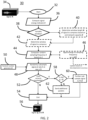
- a method 30 according to one embodiment for compressing raw collected data is shown in FIG. 2 .
- the method may be implemented by the edge nodes 12 to create a smaller sized data package that can be more efficiently transmitted over limited bandwidth to a centralized processing node such as the server 20 and/or the cloud 22.
- a centralized processing node such as the server 20 and/or the cloud 22.
- the method 30 starts at step 32 in which an input signal 34 is received in the form of a raw data signal, also indicated as a signal X. That is, the signal X (and/or the input 34) may be generated from the data collected by the relevant sensors (e.g., one or more of the sensors 14) and sent to a controller (e.g., the controller 15) of the edge node.
- a signal energy indicator (E) is determined (e.g., by the controller 15 of the corresponding edge node 12).
- the signal energy indicator ⁇ refers to one or more selected values or parameters that indicate or correspond to energy distortion in the data signal.
- parameters that can be used as, or for determining, the signal energy indicator ⁇ include variance, entropy, norm, etc., although it is to be appreciated that any other statistical or mathematical parameter that directly or indirectly identifies, quantifies, or represents the energy of the signal may be utilized, e.g., by detecting changes, variability, or fluctuations in the raw data signal.
- the parameters such as variance, entropy, norm, etc., can be calculated according to any mathematical and/or statistical methodology known or discovered in the art.
- one or more compression characteristics such as sampling frequency, sampling window length, etc. may be determined based on the signal energy indicator.
- variable window compression refers to the entire period of time (the window) over which data is to be collected for creating the final transmitted compressed data package. If it is desired to variably set the size of the window, then the method proceeds to step 40 in which the window length (N) is determined based on the signal energy indicator E, the network capacity ( ⁇ ), etc. For example, if the network capacity ⁇ indicates limited bandwidth or other resources in the network, then the window length N may be shorter than for higher bandwidth networks. Similarly, if the signal energy indicator ⁇ indicates a high degree of information content of which variance is an indicator (e.g., signal is changing frequently), then the system may set the window length N shorter to ensure the changes in the collected data sufficiently captured after the data is compressed.
- the signal energy indicator ⁇ indicates a high degree of information content of which variance is an indicator (e.g., signal is changing frequently)
- the system may set the window length N shorter to ensure the changes in the collected data sufficiently captured after the data is compressed.
- step 38 may proceed directly to step 42, e.g., utilizing a default value for the window length N and/or a previously selected/determined value for the window length N (e.g., from a previous iteration or cycle of the method 30).
- a sampling frequency ( ⁇ ) is determined based on the signal energy indicator E.
- the system may determine the sampling frequency ⁇ in proportion to the signal energy indicator E, with values of the signal energy indicator E indicating higher variability in the collected data signal X resulting in a faster sampling frequency ⁇ .
- faster sampling speeds are selected so that volatility in the collected data signal X is not lost after compression.
- the sampling frequency can be slowed down if the raw data signal isn't changing much.
- the sampling frequency ⁇ may vary widely depending on the requirements of the system. For example, the sampling frequency ⁇ may be once every few seconds, minutes, hours, etc., multiple times each second, minute, hour, etc., hundreds of times a second, or more.
- the relationship between signal energy indicator E and the sampling frequency ⁇ may be determined via a preset function or algorithm.
- the variables of the function may be set and updated over time based on the resulting accuracy of the decompression of the data compressed in accordance with the equation.
- each of the edge nodes 12 may have a table stored in memory, which enables the edge node 12, e.g., via the controller 15, to look up values for the sampling frequency ⁇ , the window length N, etc., corresponding to the computed value of the signal energy indicator E.
- the collected data signal X is subsampled based on the sampling frequency ⁇ .
- a random number generator 50 may be included to create random numbers G, from which the subsampling is randomly performed.
- the random numbers can be used as the indices for the subsampling.
- the random number generator 50 can be arranged according to any desired implementation, e.g., a software algorithm. Additionally, it is to be appreciated that "random" is not intended to mean truly random, and can include pseudo-random or other values.
- the random number generator 50 may be a seedable random number generator, such that the same values for G can be later created during decompression by another node running the same algorithm as the random number generator 50, thereby avoiding the need to separate transmit a dictionary of the indices.
- Subsampling the signal X in step 48 results in a compressed signal X.
- step 52 it may be determined whether a fixed network bandwidth is to be used. If not, then the method 30 can terminate at step 54, which results in an output 56, e.g., the compressed signal X and the window length N, as applicable, which are output regardless of size. Alternatively, if a fixed network bandwidth is to be imposed, then step 52 may proceed to step 58 at which it is determined whether the size of the compressed signal X is greater than that permitted by the network capacity ⁇ . If the compressed signal X is still too large, the compressed signal X can be further subsampled at step 60, e.g., akin to the step 48, and provided to the output 56.
- step 60 e.g., akin to the step 48
- step 58 determines that the compressed signal X is less than the network capacity ⁇
- step 62 either the compressed signal X is provided to the output 56 or the compressed signal X is augmented with additional data samples or packets. For example, additional samples may be taken from the raw data signal within the window as determined at step 42, or additional packets can be generated on data gathered outside of the window. The compressed signal X, with or without any additional packets, may then be provided to the output 56.
- the method 30 may repeat and iterate multiple successive times, e.g., the method 30 may be implemented continuously.
- the signal energy indicator ⁇ can be updated on a periodic basis and continuously updated over time in response to the collected data signal X.
- the collected data signal X may likewise be collected continuously, which may include a constant stream of data, discrete successive pulses (with or without pauses between each), etc.
- distributed systems such as the system 10 that operate in accordance with the method 30 can dynamically react (e.g., in real-time) to changing conditions as indicated by the data signal X collected by the sensors 14.
- the system 10 can automatically and dynamically change the sampling parameters (e.g., sampling frequency ⁇ , window length N, etc.) to enable more accurate reconstruction of the resulting compressed signal X.
- the system 10 can automatically and dynamically change the sampling parameters to reduce the computational resources and bandwidth requirements, thereby increasing operational efficiency in the system 10.
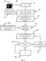
- a method 70 for decompressing the compressed data signal X is shown in FIG. 3 , which may be implemented by a centralized node, such as the gateway 18, the server 20, and/or the cloud 22.
- the method starts at step 72 at which at least a compressed data signal X is received, e.g., the output 56 from the method 30.
- the indices of the compressed data signal are retrieved based on the random numbers (G) generated by the random number generator 50. That is, as discussed above, the random number generator 50 may be a seedable random number generator, with instances of the same algorithm installed on both the edge nodes 12 and the centralized node that performs the decompression.
- the energy of the original raw data signal X is estimated based on the size of the compressed data signal X with respect to the raw data signal X.
- the output 56 may include the energy signal indictor E, which is provided to the centralized node in lieu of or in addition to the step 76.
- the decompression scheme P for solving the reconstruction problem may include solving the primal dual optimization, basis pursuit, the L1-Norm optimization problem, the linear approximation problem, any dictionary learning completion scheme, total variation compression scheme, Principal Components Analysis (PCA), smoothing, etc.
- each decompression scheme P may correspond to different values of estimated energy and/or other known parameters of the type of data compressed (sensor modality), signal window length, etc.
- decompression can be implemented via a default or preset decompression scheme.
- the compressed data signal X is recovered using a decompression algorithm corresponding to the selected decompression scheme P, resulting in a recovered data signal X P .
- a suitable basis representation to accompany decompression scheme P can also be identified. For example, signals of higher energy content can be decompressed with a different kind of basis function compared to lower energy or large signal windows.
Landscapes
- Engineering & Computer Science (AREA)
- Theoretical Computer Science (AREA)
- Computer Networks & Wireless Communication (AREA)
- Signal Processing (AREA)
- General Physics & Mathematics (AREA)
- Physics & Mathematics (AREA)
- Computational Mathematics (AREA)
- Mathematical Analysis (AREA)
- Mathematical Optimization (AREA)
- Pure & Applied Mathematics (AREA)
- General Engineering & Computer Science (AREA)
- Mobile Radio Communication Systems (AREA)
- Arrangements For Transmission Of Measured Signals (AREA)
- Compression, Expansion, Code Conversion, And Decoders (AREA)
Description
- The present disclosure is directed generally to distributed computing systems, and more particularly to enabling compressive sensing at the sensor-enabled edge nodes of distributed computing systems.
- There is an on-going trend in many industries to communicably connect together an increasingly large number of different devices that were traditionally non-connected. Examples include home and building control systems, such as connected lighting systems, inventory tracking systems, the "internet of things", and/or other "smart" or "connected" systems. Typically, the edge nodes of these systems (e.g., the luminaires in a connected lighting system) include sensors and communication modules that enable the system as a whole to more effectively, efficiently, and/or automatically react to dynamic changes in the relevant environment (e.g., home, office, warehouse, etc.). In order to make these systems feasible (e.g., economical), one typical characteristic of these systems is the limited availability of computation resources at the edge nodes (e.g., at the luminaires in a connected lighting system) and the low power bandwidth with which the nodes of the system are interconnected.
- One method to address the constraints imposed by the limited resources of a connected system includes compressive sensing in which the raw collected sensor data is compressed at the edge, and then transferred to centralized or designated network infrastructure, such as a local server or the cloud, for decompression and analysis. However, as data is increasingly compressed (e.g., in order to be timely compressed and transferred over the limited bandwidth and computational resources at the edge nodes), there is a corresponding degradation in the accuracy of the data after decompression.
- Accordingly, there is a continued need in the art for systems and methods to facilitate more timely, accurate, and efficient analysis of sensor data collected at resource-constrained edges nodes of distributed computing systems.
-
WO2017007546 purports to describe an apparatus and method for data compression using compressive sensiing in a wearable device. It purports to describe a machine-readable storage media having instructions stored thereon that when executed cause one or more processors to perform an operation comprising: receiving an input signal from a sensor, converting the input signal to a digital stream, and symmetrically paddong on either ends of the digital signal stream a portion of the digital signal stream to form a padded digital stream. -
EP2369748 purports to describe configuring a sensor chasis to remotely receive a set of parameters for compressively sampling an input signal and compressively sampling the input signal using a compressive sampling protocol based on the received parameters. The purported compressive sampling protocal is dynamically determined for achieving a desired sampling performance. - The present disclosure is directed to a method for providing compressive sensing and to an edge node of distributed computing networks. Various embodiments and implementations herein are directed to data compression and reconstruction methods in which data is first collected by the sensor(s) of one or more edge nodes of a distributed computing network. A signal energy indicator is computed, which represents or corresponds to energy distortion in the data signal, such as variance, entropy, norm, etc. Compression parameters such as sampling frequency, window length, etc. can be determined as a function of (e.g., proportional to) the signal energy indictors.
- Based on the assessed signal energy indicator, a preferred window length and/or sampling frequency of the compression is determined and parameterized by increasing the length of the window and decreasing the sampling frequency for signals of lower energy. The signal energy indictor can be automatically updated to variably adjust to changing conditions. Additionally, the compressed data signal can be decompressed based on a compression scheme selected using the energy content in the original data signal. In this way, the system can autonomously alter the characteristics of compression and decompression to variably react to changing needs while maintaining accuracy and minimizing the required transmission bandwidth and computing resources.
- All examples and features mentioned below can be combined in any technically possible way.
- Generally, in one aspect, a method for compressive sensing executed by an edge node of a distributed computing network is provided.
- Generally, in another aspect, an edge node for a distributed computing network is provided.
- It should be appreciated that all combinations of the foregoing concepts and additional concepts discussed in greater detail below (provided such concepts are not mutually inconsistent) are contemplated as being part of the inventive subject matter disclosed herein. In particular, all combinations of claimed subject matter appearing at the end of this disclosure are contemplated as being part of the inventive subject matter disclosed herein.
- In the drawings, like reference characters generally refer to the same parts throughout the different views. Also, the drawings are not necessarily to scale, emphasis instead generally being placed upon illustrating the principles of the invention.
-
FIG. 1 schematically illustrates a distributed computing system having a plurality of edge nodes according to one embodiment disclosed herein. -
FIG. 2 is a flow chart illustrating a method of compressing data with an edge node according to one embodiment disclosed herein. -
FIG. 3 is a flow chart illustrating a method of decompressing a compressed data signal according to one embodiment disclosed herein. - The present disclosure describes various embodiments of providing compressive sensing using edge nodes of a distributed computing network. More generally, Applicant has recognized and appreciated that it would be beneficial to provide a sensor-enabled edge node that is configured to adaptively adjust compression characteristics based on a signal energy indicator that is determined as an estimate or quantification of energy distortion in the raw data signal collected by the sensors of the edge node. A particular goal of utilization of certain embodiments of the present disclosure is to improve the reconstruction accuracy of compressed data, particularly with respect to data compressed by resource-limited edge nodes.
- In view of the foregoing, various embodiments and implementations are directed to data compression and reconstruction methods in which data is first collected by the sensor(s) of one or more edge nodes of a distributed computing network. A signal energy indicator is computed, which represents or corresponds to energy distortion in the data signal, such as variance, entropy, norm, etc. Compression parameters such as sampling frequency, window length, etc. can be determined as a function of (e.g., proportional to) the signal energy indictors.
- Based on the assessed signal energy indicator, a preferred window length and/or sampling frequency of the compression is determined and parameterized by increasing the length of the window and decreasing the sampling frequency for signals of lower energy. The signal energy indictor can be automatically updated to variably adjust to changing conditions thereby causing a corresponding adjustment to the window length and sampling frequency of the compression scheme. Additionally, the compressed data signal can be decompressed based on a compression scheme selected based on the energy content in the original data signal. In this way, the system can autonomously alter the characteristics of compression and decompression to variably react to changing needs while maintaining accuracy and minimizing the required transmission bandwidth and computing resources.
- Referring to
FIG. 1 , in one embodiment, a distributed computing network orsystem 10 having a plurality ofedge nodes 12 is provided. In particular,FIG. 1 illustrates thecomputing system 10 as a connected lighting system, with theedge nodes 12 provided as luminaires. However, it is to be appreciated that any other connected or "smart" computing system may be utilized, e.g., building control systems such as for automating heating, cooling, ventilation, security, noise suppression, etc., or other computing systems such as inventory tracking systems, Internet of Things systems, etc. At a minimum, each of theedge nodes 12 includes a sensor 14 (or multiple sensors) configured to collect data related to one or more parameters pertaining to the surrounding environment and/or diagnostic data pertaining to thesensor 14, acontroller 15 configured to control operation of therespective edge node 12, and a communication interface ormodule 16 that enables data communication between theedge nodes 12 and/or with other nodes or devices. - The term "centralized node" as used herein is intended to broadly refer to any designated network or processing equipment. Examples include a
gateway 18, a server 20 (e.g., local network server), and a cloud computing implementation 22 (alternatively, the "cloud 22"). Thus, the centralized nodes generally provide additional computing resources for higher level processing needs, control operation of thesystem 10, enable certain features of thesystem 10, facilitate network traffic, etc. It is to be appreciated that thesystem 10 may include one or both of theserver 20 and thecloud 22, which separately and/or together provide centralized computing resources for thesystem 10. For example, thecentral server 20 and/or thecloud 22 can be included to decompress and/or analyze the data collected by thesensors 14 and compressed at theedge nodes 12 as discussed in more detail herein. - It is to be appreciated that each of the
edge nodes 12, thegateway 18, theserver 20, and/or thecloud 22 may include suitable hardware and software to embody and enable the structure, features, and functionality disclosed herein. For example, each of thegateway 18, theserver 20, and thecloud 22 may include sensors, controllers, and communication modules akin to (e.g., but having more computational resources than) those described with respect to theedge nodes 12. Any such controllers may be, or include, a processor, memory, algorithm, or other hardware or software component. - Processors (e.g., for the controllers 15) may take any suitable form, such as a microcontroller, plural microcontrollers, circuitry, a single processor, or plural processors configured to execute software instructions. Similarly, memory (e.g., for the controllers 15) may take any suitable form or forms, including a volatile memory, such as random access memory (RAM), or non-volatile memory such as read only memory (ROM), flash memory, a hard disk drive (HDD), a solid state drive (SSD), or other data storage media. Memory may be used by a processor for the temporary storage of data during its operation. Data and software, such as the algorithms or software necessary to perform the methods and provide the features and functionality discussed herein, as well as an operating system, firmware, or other application, may be installed in memory. Communication modules as referred to herein (e.g., the communication modules 16) are arranged to enable communication between the components of the
system 10. The communication module may be or include any module, device, or means capable of enabling the transmission and/or reception of a wired or wireless communication signal, e.g., a transmitter, receiver, transceiver, antenna, etc., utilizing technologies that include, but are not limited to Wi-Fi (e.g., IEEE 802.11), Bluetooth, cellular, Ethernet, Zigbee, etc. As discussed herein, of particular note are the more relatively low-power or resource constrained technologies, such as Zigbee. - The
sensors 14 can be configured to collect any desired or selected data parameter related to the local environment, such as motion detection (e.g., radiated infrared energy), temperature, humidity, ambient noise level, ambient light level, etc. Additionally, thesensors 14 can also be configured to collect diagnostic data pertaining to the health and/or performance of thesensor 14. Thesystem 10 may be arranged to utilize this data to automate or make more efficient certain features or functionality of its components, such as theedge nodes 12. For example, referring back to an embodiment in which thesystem 10 is a connected lighting system, thesensors 14 may be motion detection sensors that enable thesystem 10 to automatically turn lights on upon detection of movement and/or to turn off lights after a preset period of time elapses in which movement is not detected. Those of ordinary skill in the art will recognize other types of distributed computing systems and collected data that can be utilized to facilitate operation of these other systems. - It is also to be appreciated that the
system 10 may be equipped with algorithms related to artificial intelligence, machine learning, artificial neural networks, etc. in order to enable advance decision making analytics and determination, such as context awareness, activity, event, or scene recognition, etc., based on the collected data. In one example, one or more algorithms may be utilized (e.g., by theserver 20 and/or the cloud 22) to process the data collected by thesensors 14 to attempt to make a higher level determination or probabilistic guess as to a corresponding activity or scenario based on that data. For example, collected motion detection data may be analyzed to estimate a number of occupants in one or more designated areas. While motion detection data only indicates detected motion, the data can be analyzed for patterns that the algorithm learns, or is trained to, recognize or correlate to a corresponding event (or a likelihood of the corresponding event occurring), such as occupant count. For example, higher levels of detected motion in a concentrated area may be interpreted as or correlated to a larger estimated occupant count. It is to be appreciated that this is merely one example and many other possibilities of higher level determinations made from collected sensor data will be appreciable to those of ordinary skill in the art. - In accordance with embodiments disclosed herein, and as discussed in more detail below, the edge nodes 12 (e.g., via the controllers 15) are configured to compress the raw data collected by the
sensors 14 by taking samples adaptively and/or across varying time-windows, based on the assessed signal energy of the data signal for the corresponding time window. Advantageously, sampling adaptively and across varying time-windows leads to significant improvements in the recovery accuracy of the decompression algorithm, which in particular enables compressive sensing to be feasible for deployment on low power or limited bandwidth communication networks (e.g., Zigbee). - A
method 30 according to one embodiment for compressing raw collected data is shown inFIG. 2 . For example, the method may be implemented by theedge nodes 12 to create a smaller sized data package that can be more efficiently transmitted over limited bandwidth to a centralized processing node such as theserver 20 and/or thecloud 22. It is noted that while generally all steps in the disclosed methods (including the method 30) can be supplemented, replaced, removed, altered, or reordered from the illustrated arrangement, those considered to be more highly optional are outlined by dotted lines in the FIGS. - The
method 30 starts atstep 32 in which aninput signal 34 is received in the form of a raw data signal, also indicated as a signal X. That is, the signal X (and/or the input 34) may be generated from the data collected by the relevant sensors (e.g., one or more of the sensors 14) and sent to a controller (e.g., the controller 15) of the edge node. Atstep 36, a signal energy indicator (E) is determined (e.g., by thecontroller 15 of the corresponding edge node 12). The signal energy indicator ε refers to one or more selected values or parameters that indicate or correspond to energy distortion in the data signal. Examples of parameters that can be used as, or for determining, the signal energy indicator ε include variance, entropy, norm, etc., although it is to be appreciated that any other statistical or mathematical parameter that directly or indirectly identifies, quantifies, or represents the energy of the signal may be utilized, e.g., by detecting changes, variability, or fluctuations in the raw data signal. Those of ordinary skill in the art will appreciate that the parameters such as variance, entropy, norm, etc., can be calculated according to any mathematical and/or statistical methodology known or discovered in the art. As discussed in more detail below, one or more compression characteristics, such as sampling frequency, sampling window length, etc. may be determined based on the signal energy indicator. - At
step 38 it is determined whether variable window compression is desired. For example, this refers to the entire period of time (the window) over which data is to be collected for creating the final transmitted compressed data package. If it is desired to variably set the size of the window, then the method proceeds to step 40 in which the window length (N) is determined based on the signal energy indicator E, the network capacity (Ø), etc. For example, if the network capacity Ø indicates limited bandwidth or other resources in the network, then the window length N may be shorter than for higher bandwidth networks. Similarly, if the signal energy indicator ε indicates a high degree of information content of which variance is an indicator (e.g., signal is changing frequently), then the system may set the window length N shorter to ensure the changes in the collected data sufficiently captured after the data is compressed. The preferred window is then set atstep 42. If a variable window size is not desired, then step 38 may proceed directly to step 42, e.g., utilizing a default value for the window length N and/or a previously selected/determined value for the window length N (e.g., from a previous iteration or cycle of the method 30). - At
step 44, a sampling frequency (δ) is determined based on the signal energy indicator E. For example, the system may determine the sampling frequency δ in proportion to the signal energy indicator E, with values of the signal energy indicator E indicating higher variability in the collected data signal X resulting in a faster sampling frequency δ. In other words, faster sampling speeds are selected so that volatility in the collected data signal X is not lost after compression. Similarly, the sampling frequency can be slowed down if the raw data signal isn't changing much. The sampling frequency δ may vary widely depending on the requirements of the system. For example, the sampling frequency δ may be once every few seconds, minutes, hours, etc., multiple times each second, minute, hour, etc., hundreds of times a second, or more. - The relationship between signal energy indicator E and the sampling frequency δ may be determined via a preset function or algorithm. To this end, the
method 30 includes astep 46 in one embodiment in which the sampling frequency δ is determined via an estimation e.g. using such an equation as µ = cεδ, where c is weighting coefficient which can be learned or fixed and µ is an indicator of the data signal size. The variables of the function may be set and updated over time based on the resulting accuracy of the decompression of the data compressed in accordance with the equation. Those of ordinary skill in the art will recognize that this is one example and that based on the disclosure herein other equations can be utilized to determine the sampling frequency δ from the signal energy indicator E. For example, each of theedge nodes 12 may have a table stored in memory, which enables theedge node 12, e.g., via thecontroller 15, to look up values for the sampling frequency δ, the window length N, etc., corresponding to the computed value of the signal energy indicator E. - At
step 48, the collected data signal X is subsampled based on the sampling frequency δ. For example, arandom number generator 50 may be included to create random numbers G, from which the subsampling is randomly performed. For example, the random numbers can be used as the indices for the subsampling. Therandom number generator 50 can be arranged according to any desired implementation, e.g., a software algorithm. Additionally, it is to be appreciated that "random" is not intended to mean truly random, and can include pseudo-random or other values. As will be appreciated in view of the below-discussion regarding decompression, therandom number generator 50 may be a seedable random number generator, such that the same values for G can be later created during decompression by another node running the same algorithm as therandom number generator 50, thereby avoiding the need to separate transmit a dictionary of the indices. Subsampling the signal X instep 48 results in a compressed signal X. - At
step 52, it may be determined whether a fixed network bandwidth is to be used. If not, then themethod 30 can terminate atstep 54, which results in anoutput 56, e.g., the compressed signal X and the window length N, as applicable, which are output regardless of size. Alternatively, if a fixed network bandwidth is to be imposed, then step 52 may proceed to step 58 at which it is determined whether the size of the compressed signal X is greater than that permitted by the network capacity Ø. If the compressed signal X is still too large, the compressed signal X can be further subsampled atstep 60, e.g., akin to thestep 48, and provided to theoutput 56. Ifstep 58 determines that the compressed signal X is less than the network capacity Ø, then atstep 62 either the compressed signal X is provided to theoutput 56 or the compressed signal X is augmented with additional data samples or packets. For example, additional samples may be taken from the raw data signal within the window as determined atstep 42, or additional packets can be generated on data gathered outside of the window. The compressed signal X, with or without any additional packets, may then be provided to theoutput 56. - As discussed herein, the
method 30 may repeat and iterate multiple successive times, e.g., themethod 30 may be implemented continuously. For example, the signal energy indicator ε can be updated on a periodic basis and continuously updated over time in response to the collected data signal X. The collected data signal X may likewise be collected continuously, which may include a constant stream of data, discrete successive pulses (with or without pauses between each), etc. In any case, distributed systems such as thesystem 10 that operate in accordance with themethod 30 can dynamically react (e.g., in real-time) to changing conditions as indicated by the data signal X collected by thesensors 14. For example, as the signal energy indicator E indicates more energy in the data signal X collected by thesensors 14, thesystem 10 can automatically and dynamically change the sampling parameters (e.g., sampling frequency δ, window length N, etc.) to enable more accurate reconstruction of the resulting compressed signal X. Similarly, as the signal energy indicator E indicates less energy in the data signal X collected by thesensors 14, thesystem 10 can automatically and dynamically change the sampling parameters to reduce the computational resources and bandwidth requirements, thereby increasing operational efficiency in thesystem 10. - A
method 70 for decompressing the compressed data signal X is shown inFIG. 3 , which may be implemented by a centralized node, such as thegateway 18, theserver 20, and/or thecloud 22. The method starts atstep 72 at which at least a compressed data signal X is received, e.g., theoutput 56 from themethod 30. Atstep 74, the indices of the compressed data signal are retrieved based on the random numbers (G) generated by therandom number generator 50. That is, as discussed above, therandom number generator 50 may be a seedable random number generator, with instances of the same algorithm installed on both theedge nodes 12 and the centralized node that performs the decompression. - At
step 76, the energy of the original raw data signal X is estimated based on the size of the compressed data signal X with respect to the raw data signal X. In one embodiment, theoutput 56 may include the energy signal indictor E, which is provided to the centralized node in lieu of or in addition to thestep 76. Atstep 78, it can be determined whether it is desired to select a preferred compression scheme based on the estimated energy fromstep 76. If so, then at astep 80, a decompression scheme (P) may be provided. For example, the decompression scheme P for solving the reconstruction problem may include solving the primal dual optimization, basis pursuit, the L1-Norm optimization problem, the linear approximation problem, any dictionary learning completion scheme, total variation compression scheme, Principal Components Analysis (PCA), smoothing, etc. For example, each decompression scheme P may correspond to different values of estimated energy and/or other known parameters of the type of data compressed (sensor modality), signal window length, etc. Alternatively in lieu of thesteps - At
step 82, the compressed data signal X is recovered using a decompression algorithm corresponding to the selected decompression scheme P, resulting in a recovered data signal XP. A suitable basis representation to accompany decompression scheme P can also be identified. For example, signals of higher energy content can be decompressed with a different kind of basis function compared to lower energy or large signal windows. Atstep 84, it is determined whether any new or additional packets have been sent by the edge node 12 (e.g., via the step 62). If yes, atstep 86 any improvements in XP with respect to the additional packets can be determined as the method is returned to step 82 for decompression of the additional packets. If new packets are not received or available, then themethod 70 may terminate atstep 88 with the recovered data signal XP as an output. - While several inventive embodiments have been described and illustrated herein, those of ordinary skill in the art will readily envision a variety of other means and/or structures for performing the function and/or obtaining the results and/or one or more of the advantages described herein, and each of such variations and/or modifications is deemed to be within the scope of the inventive embodiments described herein. More generally, those skilled in the art will readily appreciate that all parameters, dimensions, materials, and configurations described herein are meant to be exemplary and that the actual parameters, dimensions, materials, and/or configurations will depend upon the specific application or applications for which the inventive teachings is/are used. Those skilled in the art will recognize, or be able to ascertain using no more than routine experimentation, many equivalents to the specific inventive embodiments described herein. It is, therefore, to be understood that the foregoing embodiments are presented by way of example only and that, within the scope of the appended claims and equivalents thereto, inventive embodiments may be practiced otherwise than as specifically described and claimed. Inventive embodiments of the present disclosure are directed to each individual feature, system, article, material, kit, and/or method described herein. In addition, any combination of two or more such features, systems, articles, materials, kits, and/or methods, if such features, systems, articles, materials, kits, and/or methods are not mutually inconsistent, is included within the inventive scope of the present disclosure. The invention is defined by the appended claims.
- The phrase "and/or," as used herein in the specification and in the claims, should be understood to mean "either or both" of the elements so conjoined, i.e., elements that are conjunctively present in some cases and disjunctively present in other cases. Multiple elements listed with "and/or" should be construed in the same fashion, i.e., "one or more" of the elements so conjoined. Other elements may optionally be present other than the elements specifically identified by the "and/or" clause, whether related or unrelated to those elements specifically identified. As used herein in the specification and in the claims, "or" should be understood to have the same meaning as "and/or" as defined above.
- It should also be understood that, unless clearly indicated to the contrary, in the method claimed herein that include more than one step or act, the order of the steps or acts of the method is not necessarily limited to the order in which the steps or acts of the method are recited.
Claims (11)
- A method for compressive sensing executed by an edge node (12) of a resource-constrained distributed computing network (10), wherein the edge node is provided with a fixed network capacity (Ø) the method comprising:collecting (32) a raw data signal (X) continuously by a sensor (14) of the edge node of the resource-constrained distributed computing network;dynamically updating (36) a signal energy indicator (Σ) that quantifies a variance in the raw data signal;determining (40, 42, 44) one or more compression characteristics as a function of the signal energy indicator as the signal energy indicator is updated;subsampling (48) the raw data signal in accordance with current values of the one or more compression characteristics to create a compressed data signal (X);comparing a size of the compressed data signal to the fixed network capacity (Ø) and further subsampling the compressed data signal to further compress the compressed data signal to fit the fixed network capacity if the size is greater than that permitted by the fixed network capacity; andtransmitting an output (56) that includes the compressed data signal to a centralized node (18, 20, 22) of the resource-constrained distributed computing network.
- The method of claim 1, wherein the one or more compression characteristics includes a sampling frequency (δ), a signal window length (N), or a combination including at least one of the foregoing.
- The method of claim 2, wherein the signal window length is also determined based on the fixed network capacity (Ø) of the distributed computing network available to the edge node.
- The method of claim 2, wherein the subsampling includes at least one of randomly subsampling and randomly down-sampling the raw data signal with respect to the sampling frequency.
- The method of claim 4, further comprising generating random numbers with a random number generator (50) and utilizing the random numbers as indices for the at least one of subsampling and down-sampling.
- The method of claim 5, wherein the random number generator is a seedable random number generator, such that the random numbers can be recreated by seeding a second instance of the random number generator at the centralized node during decompression of the compressed data signal.
- The method of claim 6, further comprising sending additional samples or packets from the raw data signal if the size of the compressed data signal is less than that permitted by the fixed network capacity.
- An edge node (12) for a resource-constrained distributed computing network (10), wherein the edge node (12) is provided with a fixed network capacity (Ø), the edge node (12) comprising:a communication module (16) configured to enable data communication over the resource-constrained distributed computing network;a sensor (14) configured to continuously collect a raw data signal (X) related to one or more parameters of an environment local to the edge node; anda controller (15) configured to:receive the raw data signal;dynamically update a signal energy indicator (Σ) that quantifies a variance in the raw data signal;determine one or more compression characteristics as a function of the signal energy indicator as the signal energy indicator is updated;subsample the raw data signal in accordance with current values of the one or more compression characteristics to create a compressed data signal (X);compare a size of the compressed data signal to the fixed network capacity (Ø) and further subsample the compressed data signal to further compress the compressed data signal to fit the fixed network capacity if the size is greater than that permitted by the fixed network capacity; andtransmit an output (56) that includes the compressed data signal to a centralized node (18, 20, 22) on the resource-constrained distributed computing network.
- The edge node of claim 8, wherein the edge node comprises a luminaire.
- The edge node of claim 9, wherein the sensor is a motion detection sensor.
- A system (10) including the edge node of claim 8 and a centralized node, wherein the centralized node is a gateway (18), a server (20), a cloud computing implementation (22), or a combination including at least one of the foregoing.
Applications Claiming Priority (3)
| Application Number | Priority Date | Filing Date | Title |
|---|---|---|---|
| US201862715472P | 2018-08-07 | 2018-08-07 | |
| EP18190723 | 2018-08-24 | ||
| PCT/EP2019/070592 WO2020030488A1 (en) | 2018-08-07 | 2019-07-31 | Compressive sensing systems and methods using edge nodes of distributed computing networks |
Publications (2)
| Publication Number | Publication Date |
|---|---|
| EP3834441A1 EP3834441A1 (en) | 2021-06-16 |
| EP3834441B1 true EP3834441B1 (en) | 2023-10-04 |
Family
ID=67513525
Family Applications (1)
| Application Number | Title | Priority Date | Filing Date |
|---|---|---|---|
| EP19748532.9A Active EP3834441B1 (en) | 2018-08-07 | 2019-07-31 | Compressive sensing method and edge node of distributed computing networks |
Country Status (5)
| Country | Link |
|---|---|
| US (1) | US11496150B2 (en) |
| EP (1) | EP3834441B1 (en) |
| JP (1) | JP7413352B2 (en) |
| CN (1) | CN112534842B (en) |
| WO (1) | WO2020030488A1 (en) |
Families Citing this family (2)
| Publication number | Priority date | Publication date | Assignee | Title |
|---|---|---|---|---|
| CN113641684B (en) * | 2021-10-18 | 2022-01-25 | 上海英哈科技有限公司 | IoT big data processing device and method |
| CN118118553B (en) * | 2024-04-30 | 2024-08-20 | 南京中科智慧生态科技有限公司 | Intelligent sensor data caching method and system based on edge calculation |
Family Cites Families (27)
| Publication number | Priority date | Publication date | Assignee | Title |
|---|---|---|---|---|
| US4546342A (en) | 1983-12-14 | 1985-10-08 | Digital Recording Research Limited Partnership | Data compression method and apparatus |
| JP3141450B2 (en) | 1991-09-30 | 2001-03-05 | ソニー株式会社 | Audio signal processing method |
| GB9625661D0 (en) * | 1996-12-11 | 1997-01-29 | Hewlett Packard Co | A method and apparatus for compression of electronic ink |
| CA2566638A1 (en) * | 2003-05-13 | 2004-11-25 | Medical Insight A/S | Method and system for remote and adaptive visualization of graphical image data |
| FR2898757A1 (en) * | 2006-03-14 | 2007-09-21 | Canon Kk | METHOD AND DEVICE FOR ADAPTING A TIME FREQUENCY OF A SEQUENCE OF VIDEO IMAGES |
| US7558685B2 (en) * | 2006-11-29 | 2009-07-07 | Samplify Systems, Inc. | Frequency resolution using compression |
| US7554467B2 (en) * | 2007-07-31 | 2009-06-30 | Novell, Inc. | Network content in dictionary-based (DE)compression |
| US7930436B1 (en) * | 2009-03-09 | 2011-04-19 | Znosko Dmitry Y | System and method for dynamically adjusting data compression parameters |
| US20110231155A1 (en) | 2010-03-22 | 2011-09-22 | General Electric Company | Dynamically configurable sensor chassis |
| KR20120062551A (en) * | 2010-12-06 | 2012-06-14 | 한국전자통신연구원 | Device and method for transmitting digital video, device and method for receiving digital video, system transmitting and receiving digital video |
| WO2013006697A2 (en) * | 2011-07-05 | 2013-01-10 | Massachusetts Institute Of Technology | Energy-efficient time-stampless adaptive nonuniform sampling |
| CN102340667B (en) * | 2011-09-16 | 2013-06-12 | 沈阳航空航天大学 | Distributed image transmission method oriented to wireless multimedia sensor network |
| JP5670860B2 (en) | 2011-10-25 | 2015-02-18 | 日本電信電話株式会社 | Signal processing system and signal processing method |
| CN102833000B (en) * | 2012-08-14 | 2015-06-17 | 电信科学技术研究院 | Method and equipment for data transmission |
| CN102821303B (en) * | 2012-08-31 | 2016-06-29 | 哈尔滨工程大学 | A kind of Pixel-level video information network real-time graded compression transmitting method |
| CN103347268B (en) * | 2013-06-05 | 2016-03-30 | 杭州电子科技大学 | Based on the self-adapting compressing reconstructing method of energy efficiency observation in cognitive sensor network |
| US9788721B2 (en) * | 2014-07-22 | 2017-10-17 | Biobit, Inc. | Low-power activity monitoring |
| EP3189310B1 (en) | 2014-09-04 | 2018-10-03 | PCMS Holdings, Inc. | System and method for sensor node localization and sensor network organization based on contextual event detection |
| CN104598735A (en) * | 2015-01-23 | 2015-05-06 | 四川大学 | Time-varying homotopy algorithm based on L1 homotopy recovery algorithm |
| US10015272B2 (en) * | 2015-03-12 | 2018-07-03 | Intel Corporation | Method and apparatus for compaction of data received over a network |
| JP6873914B2 (en) | 2015-07-03 | 2021-05-19 | インテル・コーポレーション | Devices and methods for data compression in wearable devices |
| CN105120469B (en) * | 2015-07-06 | 2016-09-07 | 湘潭大学 | The low information density method of data capture of quality scalable based on compressed sensing |
| US9496894B1 (en) * | 2015-10-21 | 2016-11-15 | GE Lighting Solutions, LLC | System and method for data compression over a communication network |
| CN105676222B (en) * | 2015-10-30 | 2018-09-21 | 中国人民解放军空军工程大学 | A kind of data of synthetic aperture radar self-adapting compressing and method for fast reconstruction |
| WO2017114579A1 (en) | 2015-12-30 | 2017-07-06 | Teraki Gmbh | Method and system for obtaining and storing sensor data |
| US10435869B2 (en) * | 2016-12-22 | 2019-10-08 | Navilas Solutions, Inc. | Spatial-temporal compression of sensing data for sensor network |
| US10149131B2 (en) * | 2017-01-24 | 2018-12-04 | Intel Corporation | Compressive sensing for power efficient data aggregation in a wireless sensor network |
-
2019
- 2019-07-31 JP JP2021506533A patent/JP7413352B2/en active Active
- 2019-07-31 CN CN201980052244.5A patent/CN112534842B/en active Active
- 2019-07-31 WO PCT/EP2019/070592 patent/WO2020030488A1/en not_active Ceased
- 2019-07-31 US US17/266,766 patent/US11496150B2/en active Active
- 2019-07-31 EP EP19748532.9A patent/EP3834441B1/en active Active
Also Published As
| Publication number | Publication date |
|---|---|
| CN112534842B (en) | 2024-05-28 |
| US11496150B2 (en) | 2022-11-08 |
| JP7413352B2 (en) | 2024-01-15 |
| EP3834441A1 (en) | 2021-06-16 |
| CN112534842A (en) | 2021-03-19 |
| WO2020030488A1 (en) | 2020-02-13 |
| US20210314001A1 (en) | 2021-10-07 |
| JP2021533667A (en) | 2021-12-02 |
Similar Documents
| Publication | Publication Date | Title |
|---|---|---|
| US11108575B2 (en) | Training models for IOT devices | |
| US11412574B2 (en) | Split predictions for IoT devices | |
| US20140184273A1 (en) | Energy-Efficient Time-Stampless Adaptive Nonuniform Sampling | |
| US20220178978A1 (en) | Compressing information in an end node using an autoencoder neural network | |
| US11799983B2 (en) | Ranking internet of things (IoT) data based on IoT analytics services | |
| US11496150B2 (en) | Compressive sensing systems and methods using edge nodes of distributed computing networks | |
| US20190392292A1 (en) | Method and system for optimizing event prediction in data systems | |
| Charalampidis et al. | Rate-adaptive compressive sensing for iot applications | |
| CN117579101A (en) | Control method and system of carrier communication module | |
| Kadhum Idrees et al. | SZ4IoT: an adaptive lightweight lossy compression algorithm for diverse IoT devices and data types: SK Idrees et al. | |
| CN112534427B (en) | System and method for compressing sensor data using clustering and shape matching in edge nodes of a distributed computing network | |
| US11050858B2 (en) | Programmable data router | |
| JP2021533667A5 (en) | ||
| CN119629172A (en) | A switch control method and system for Internet of Things based on edge computing | |
| EP3659321B1 (en) | Tiered data processing for iot device clusters | |
| WO2020030527A1 (en) | Systems and methods for optimizing compression and reconstruction of sensor data in distributed computing networks | |
| Frederiksen et al. | Link-Aware Energy-Frugal Continual Learning for Fault Detection in IoT Networks | |
| Press et al. | DSP: a deep learning based approach to extend the lifetime of wireless sensor networks | |
| CN120389910B (en) | Abnormal traffic detection network training method, abnormal traffic detection method and device | |
| CN114448599B (en) | Intrusion detection method and system | |
| CN120724218B (en) | Electromechanical point detection equipment fault diagnosis method based on deep neural network | |
| CN119575040A (en) | A method and device for collecting test data of electric power equipment based on multi-source data fusion | |
| Firos | Semantic Based Emotional Voice Coding Using Feed Forward Artificial Neural Network for Smart Home Devices | |
| CN121037459A (en) | A method and system for adaptive compression and transmission of multi-source heterogeneous data based on DRL | |
| KR20240020061A (en) | Cloud volume analysis using deep learning-based sky image and automatic cloud data collection device for confirming the existence of the sun and method using the same |
Legal Events
| Date | Code | Title | Description |
|---|---|---|---|
| STAA | Information on the status of an ep patent application or granted ep patent |
Free format text: STATUS: UNKNOWN |
|
| STAA | Information on the status of an ep patent application or granted ep patent |
Free format text: STATUS: THE INTERNATIONAL PUBLICATION HAS BEEN MADE |
|
| PUAI | Public reference made under article 153(3) epc to a published international application that has entered the european phase |
Free format text: ORIGINAL CODE: 0009012 |
|
| STAA | Information on the status of an ep patent application or granted ep patent |
Free format text: STATUS: REQUEST FOR EXAMINATION WAS MADE |
|
| 17P | Request for examination filed |
Effective date: 20210309 |
|
| AK | Designated contracting states |
Kind code of ref document: A1 Designated state(s): AL AT BE BG CH CY CZ DE DK EE ES FI FR GB GR HR HU IE IS IT LI LT LU LV MC MK MT NL NO PL PT RO RS SE SI SK SM TR |
|
| DAV | Request for validation of the european patent (deleted) | ||
| DAX | Request for extension of the european patent (deleted) | ||
| STAA | Information on the status of an ep patent application or granted ep patent |
Free format text: STATUS: EXAMINATION IS IN PROGRESS |
|
| 17Q | First examination report despatched |
Effective date: 20221115 |
|
| REG | Reference to a national code |
Ref country code: DE Ref country code: DE Ref legal event code: R079 Ref document number: 602019038644 Country of ref document: DE Free format text: PREVIOUS MAIN CLASS: H04W0004700000 Ipc: H04W0004180000 |
|
| GRAP | Despatch of communication of intention to grant a patent |
Free format text: ORIGINAL CODE: EPIDOSNIGR1 |
|
| STAA | Information on the status of an ep patent application or granted ep patent |
Free format text: STATUS: GRANT OF PATENT IS INTENDED |
|
| RIC1 | Information provided on ipc code assigned before grant |
Ipc: H03M 7/30 20060101ALI20230404BHEP Ipc: H04W 4/38 20180101ALI20230404BHEP Ipc: H04W 4/18 20090101AFI20230404BHEP |
|
| INTG | Intention to grant announced |
Effective date: 20230503 |
|
| P01 | Opt-out of the competence of the unified patent court (upc) registered |
Effective date: 20230530 |
|
| GRAS | Grant fee paid |
Free format text: ORIGINAL CODE: EPIDOSNIGR3 |
|
| GRAA | (expected) grant |
Free format text: ORIGINAL CODE: 0009210 |
|
| STAA | Information on the status of an ep patent application or granted ep patent |
Free format text: STATUS: THE PATENT HAS BEEN GRANTED |
|
| AK | Designated contracting states |
Kind code of ref document: B1 Designated state(s): AL AT BE BG CH CY CZ DE DK EE ES FI FR GB GR HR HU IE IS IT LI LT LU LV MC MK MT NL NO PL PT RO RS SE SI SK SM TR |
|
| REG | Reference to a national code |
Ref country code: GB Ref legal event code: FG4D |
|
| REG | Reference to a national code |
Ref country code: CH Ref legal event code: EP |
|
| REG | Reference to a national code |
Ref country code: DE Ref legal event code: R096 Ref document number: 602019038644 Country of ref document: DE |
|
| REG | Reference to a national code |
Ref country code: IE Ref legal event code: FG4D |
|
| REG | Reference to a national code |
Ref country code: LT Ref legal event code: MG9D |
|
| REG | Reference to a national code |
Ref country code: NL Ref legal event code: MP Effective date: 20231004 |
|
| REG | Reference to a national code |
Ref country code: AT Ref legal event code: MK05 Ref document number: 1619070 Country of ref document: AT Kind code of ref document: T Effective date: 20231004 |
|
| PG25 | Lapsed in a contracting state [announced via postgrant information from national office to epo] |
Ref country code: NL Free format text: LAPSE BECAUSE OF FAILURE TO SUBMIT A TRANSLATION OF THE DESCRIPTION OR TO PAY THE FEE WITHIN THE PRESCRIBED TIME-LIMIT Effective date: 20231004 |
|
| PG25 | Lapsed in a contracting state [announced via postgrant information from national office to epo] |
Ref country code: GR Free format text: LAPSE BECAUSE OF FAILURE TO SUBMIT A TRANSLATION OF THE DESCRIPTION OR TO PAY THE FEE WITHIN THE PRESCRIBED TIME-LIMIT Effective date: 20240105 |
|
| PG25 | Lapsed in a contracting state [announced via postgrant information from national office to epo] |
Ref country code: IS Free format text: LAPSE BECAUSE OF FAILURE TO SUBMIT A TRANSLATION OF THE DESCRIPTION OR TO PAY THE FEE WITHIN THE PRESCRIBED TIME-LIMIT Effective date: 20240204 |
|
| PG25 | Lapsed in a contracting state [announced via postgrant information from national office to epo] |
Ref country code: LT Free format text: LAPSE BECAUSE OF FAILURE TO SUBMIT A TRANSLATION OF THE DESCRIPTION OR TO PAY THE FEE WITHIN THE PRESCRIBED TIME-LIMIT Effective date: 20231004 |
|
| PG25 | Lapsed in a contracting state [announced via postgrant information from national office to epo] |
Ref country code: AT Free format text: LAPSE BECAUSE OF FAILURE TO SUBMIT A TRANSLATION OF THE DESCRIPTION OR TO PAY THE FEE WITHIN THE PRESCRIBED TIME-LIMIT Effective date: 20231004 |
|
| PG25 | Lapsed in a contracting state [announced via postgrant information from national office to epo] |
Ref country code: ES Free format text: LAPSE BECAUSE OF FAILURE TO SUBMIT A TRANSLATION OF THE DESCRIPTION OR TO PAY THE FEE WITHIN THE PRESCRIBED TIME-LIMIT Effective date: 20231004 |
|
| PG25 | Lapsed in a contracting state [announced via postgrant information from national office to epo] |
Ref country code: LT Free format text: LAPSE BECAUSE OF FAILURE TO SUBMIT A TRANSLATION OF THE DESCRIPTION OR TO PAY THE FEE WITHIN THE PRESCRIBED TIME-LIMIT Effective date: 20231004 Ref country code: IS Free format text: LAPSE BECAUSE OF FAILURE TO SUBMIT A TRANSLATION OF THE DESCRIPTION OR TO PAY THE FEE WITHIN THE PRESCRIBED TIME-LIMIT Effective date: 20240204 Ref country code: GR Free format text: LAPSE BECAUSE OF FAILURE TO SUBMIT A TRANSLATION OF THE DESCRIPTION OR TO PAY THE FEE WITHIN THE PRESCRIBED TIME-LIMIT Effective date: 20240105 Ref country code: ES Free format text: LAPSE BECAUSE OF FAILURE TO SUBMIT A TRANSLATION OF THE DESCRIPTION OR TO PAY THE FEE WITHIN THE PRESCRIBED TIME-LIMIT Effective date: 20231004 Ref country code: BG Free format text: LAPSE BECAUSE OF FAILURE TO SUBMIT A TRANSLATION OF THE DESCRIPTION OR TO PAY THE FEE WITHIN THE PRESCRIBED TIME-LIMIT Effective date: 20240104 Ref country code: AT Free format text: LAPSE BECAUSE OF FAILURE TO SUBMIT A TRANSLATION OF THE DESCRIPTION OR TO PAY THE FEE WITHIN THE PRESCRIBED TIME-LIMIT Effective date: 20231004 Ref country code: PT Free format text: LAPSE BECAUSE OF FAILURE TO SUBMIT A TRANSLATION OF THE DESCRIPTION OR TO PAY THE FEE WITHIN THE PRESCRIBED TIME-LIMIT Effective date: 20240205 |
|
| PG25 | Lapsed in a contracting state [announced via postgrant information from national office to epo] |
Ref country code: SE Free format text: LAPSE BECAUSE OF FAILURE TO SUBMIT A TRANSLATION OF THE DESCRIPTION OR TO PAY THE FEE WITHIN THE PRESCRIBED TIME-LIMIT Effective date: 20231004 Ref country code: RS Free format text: LAPSE BECAUSE OF FAILURE TO SUBMIT A TRANSLATION OF THE DESCRIPTION OR TO PAY THE FEE WITHIN THE PRESCRIBED TIME-LIMIT Effective date: 20231004 Ref country code: PL Free format text: LAPSE BECAUSE OF FAILURE TO SUBMIT A TRANSLATION OF THE DESCRIPTION OR TO PAY THE FEE WITHIN THE PRESCRIBED TIME-LIMIT Effective date: 20231004 Ref country code: NO Free format text: LAPSE BECAUSE OF FAILURE TO SUBMIT A TRANSLATION OF THE DESCRIPTION OR TO PAY THE FEE WITHIN THE PRESCRIBED TIME-LIMIT Effective date: 20240104 Ref country code: LV Free format text: LAPSE BECAUSE OF FAILURE TO SUBMIT A TRANSLATION OF THE DESCRIPTION OR TO PAY THE FEE WITHIN THE PRESCRIBED TIME-LIMIT Effective date: 20231004 Ref country code: HR Free format text: LAPSE BECAUSE OF FAILURE TO SUBMIT A TRANSLATION OF THE DESCRIPTION OR TO PAY THE FEE WITHIN THE PRESCRIBED TIME-LIMIT Effective date: 20231004 |
|
| REG | Reference to a national code |
Ref country code: DE Ref legal event code: R097 Ref document number: 602019038644 Country of ref document: DE |
|
| PG25 | Lapsed in a contracting state [announced via postgrant information from national office to epo] |
Ref country code: DK Free format text: LAPSE BECAUSE OF FAILURE TO SUBMIT A TRANSLATION OF THE DESCRIPTION OR TO PAY THE FEE WITHIN THE PRESCRIBED TIME-LIMIT Effective date: 20231004 |
|
| PG25 | Lapsed in a contracting state [announced via postgrant information from national office to epo] |
Ref country code: CZ Free format text: LAPSE BECAUSE OF FAILURE TO SUBMIT A TRANSLATION OF THE DESCRIPTION OR TO PAY THE FEE WITHIN THE PRESCRIBED TIME-LIMIT Effective date: 20231004 |
|
| PG25 | Lapsed in a contracting state [announced via postgrant information from national office to epo] |
Ref country code: SK Free format text: LAPSE BECAUSE OF FAILURE TO SUBMIT A TRANSLATION OF THE DESCRIPTION OR TO PAY THE FEE WITHIN THE PRESCRIBED TIME-LIMIT Effective date: 20231004 |
|
| PG25 | Lapsed in a contracting state [announced via postgrant information from national office to epo] |
Ref country code: SM Free format text: LAPSE BECAUSE OF FAILURE TO SUBMIT A TRANSLATION OF THE DESCRIPTION OR TO PAY THE FEE WITHIN THE PRESCRIBED TIME-LIMIT Effective date: 20231004 Ref country code: SK Free format text: LAPSE BECAUSE OF FAILURE TO SUBMIT A TRANSLATION OF THE DESCRIPTION OR TO PAY THE FEE WITHIN THE PRESCRIBED TIME-LIMIT Effective date: 20231004 Ref country code: RO Free format text: LAPSE BECAUSE OF FAILURE TO SUBMIT A TRANSLATION OF THE DESCRIPTION OR TO PAY THE FEE WITHIN THE PRESCRIBED TIME-LIMIT Effective date: 20231004 Ref country code: IT Free format text: LAPSE BECAUSE OF FAILURE TO SUBMIT A TRANSLATION OF THE DESCRIPTION OR TO PAY THE FEE WITHIN THE PRESCRIBED TIME-LIMIT Effective date: 20231004 Ref country code: EE Free format text: LAPSE BECAUSE OF FAILURE TO SUBMIT A TRANSLATION OF THE DESCRIPTION OR TO PAY THE FEE WITHIN THE PRESCRIBED TIME-LIMIT Effective date: 20231004 Ref country code: DK Free format text: LAPSE BECAUSE OF FAILURE TO SUBMIT A TRANSLATION OF THE DESCRIPTION OR TO PAY THE FEE WITHIN THE PRESCRIBED TIME-LIMIT Effective date: 20231004 Ref country code: CZ Free format text: LAPSE BECAUSE OF FAILURE TO SUBMIT A TRANSLATION OF THE DESCRIPTION OR TO PAY THE FEE WITHIN THE PRESCRIBED TIME-LIMIT Effective date: 20231004 |
|
| PLBE | No opposition filed within time limit |
Free format text: ORIGINAL CODE: 0009261 |
|
| STAA | Information on the status of an ep patent application or granted ep patent |
Free format text: STATUS: NO OPPOSITION FILED WITHIN TIME LIMIT |
|
| 26N | No opposition filed |
Effective date: 20240705 |
|
| PG25 | Lapsed in a contracting state [announced via postgrant information from national office to epo] |
Ref country code: SI Free format text: LAPSE BECAUSE OF FAILURE TO SUBMIT A TRANSLATION OF THE DESCRIPTION OR TO PAY THE FEE WITHIN THE PRESCRIBED TIME-LIMIT Effective date: 20231004 |
|
| PG25 | Lapsed in a contracting state [announced via postgrant information from national office to epo] |
Ref country code: SI Free format text: LAPSE BECAUSE OF FAILURE TO SUBMIT A TRANSLATION OF THE DESCRIPTION OR TO PAY THE FEE WITHIN THE PRESCRIBED TIME-LIMIT Effective date: 20231004 |
|
| PG25 | Lapsed in a contracting state [announced via postgrant information from national office to epo] |
Ref country code: MC Free format text: LAPSE BECAUSE OF FAILURE TO SUBMIT A TRANSLATION OF THE DESCRIPTION OR TO PAY THE FEE WITHIN THE PRESCRIBED TIME-LIMIT Effective date: 20231004 |
|
| REG | Reference to a national code |
Ref country code: CH Ref legal event code: PL |
|
| PG25 | Lapsed in a contracting state [announced via postgrant information from national office to epo] |
Ref country code: LU Free format text: LAPSE BECAUSE OF NON-PAYMENT OF DUE FEES Effective date: 20240731 |
|
| PG25 | Lapsed in a contracting state [announced via postgrant information from national office to epo] |
Ref country code: LU Free format text: LAPSE BECAUSE OF NON-PAYMENT OF DUE FEES Effective date: 20240731 |
|
| PG25 | Lapsed in a contracting state [announced via postgrant information from national office to epo] |
Ref country code: BE Free format text: LAPSE BECAUSE OF NON-PAYMENT OF DUE FEES Effective date: 20240731 Ref country code: CH Free format text: LAPSE BECAUSE OF NON-PAYMENT OF DUE FEES Effective date: 20240731 |
|
| REG | Reference to a national code |
Ref country code: BE Ref legal event code: MM Effective date: 20240731 |
|
| PG25 | Lapsed in a contracting state [announced via postgrant information from national office to epo] |
Ref country code: IE Free format text: LAPSE BECAUSE OF NON-PAYMENT OF DUE FEES Effective date: 20240731 |
|
| PG25 | Lapsed in a contracting state [announced via postgrant information from national office to epo] |
Ref country code: FI Free format text: LAPSE BECAUSE OF FAILURE TO SUBMIT A TRANSLATION OF THE DESCRIPTION OR TO PAY THE FEE WITHIN THE PRESCRIBED TIME-LIMIT Effective date: 20231004 |
|
| PGFP | Annual fee paid to national office [announced via postgrant information from national office to epo] |
Ref country code: DE Payment date: 20250926 Year of fee payment: 7 |
|
| PGFP | Annual fee paid to national office [announced via postgrant information from national office to epo] |
Ref country code: GB Payment date: 20250722 Year of fee payment: 7 |
|
| PGFP | Annual fee paid to national office [announced via postgrant information from national office to epo] |
Ref country code: FR Payment date: 20250725 Year of fee payment: 7 |
|
| PG25 | Lapsed in a contracting state [announced via postgrant information from national office to epo] |
Ref country code: CY Free format text: LAPSE BECAUSE OF FAILURE TO SUBMIT A TRANSLATION OF THE DESCRIPTION OR TO PAY THE FEE WITHIN THE PRESCRIBED TIME-LIMIT; INVALID AB INITIO Effective date: 20190731 |
|
| PG25 | Lapsed in a contracting state [announced via postgrant information from national office to epo] |
Ref country code: HU Free format text: LAPSE BECAUSE OF FAILURE TO SUBMIT A TRANSLATION OF THE DESCRIPTION OR TO PAY THE FEE WITHIN THE PRESCRIBED TIME-LIMIT; INVALID AB INITIO Effective date: 20190731 |
|
| PG25 | Lapsed in a contracting state [announced via postgrant information from national office to epo] |
Ref country code: TR Free format text: LAPSE BECAUSE OF FAILURE TO SUBMIT A TRANSLATION OF THE DESCRIPTION OR TO PAY THE FEE WITHIN THE PRESCRIBED TIME-LIMIT Effective date: 20231004 |