EP3834379B1 - Inter-slice sharing in 5g core networks - Google Patents
Inter-slice sharing in 5g core networks Download PDFInfo
- Publication number
- EP3834379B1 EP3834379B1 EP18769070.6A EP18769070A EP3834379B1 EP 3834379 B1 EP3834379 B1 EP 3834379B1 EP 18769070 A EP18769070 A EP 18769070A EP 3834379 B1 EP3834379 B1 EP 3834379B1
- Authority
- EP
- European Patent Office
- Prior art keywords
- nsi
- network
- communication
- communication entity
- virtual switch
- Prior art date
- Legal status (The legal status is an assumption and is not a legal conclusion. Google has not performed a legal analysis and makes no representation as to the accuracy of the status listed.)
- Active
Links
Images


Classifications
-
- H—ELECTRICITY
- H04—ELECTRIC COMMUNICATION TECHNIQUE
- H04L—TRANSMISSION OF DIGITAL INFORMATION, e.g. TELEGRAPHIC COMMUNICATION
- H04L45/00—Routing or path finding of packets in data switching networks
-
- G—PHYSICS
- G06—COMPUTING OR CALCULATING; COUNTING
- G06F—ELECTRIC DIGITAL DATA PROCESSING
- G06F9/00—Arrangements for program control, e.g. control units
- G06F9/06—Arrangements for program control, e.g. control units using stored programs, i.e. using an internal store of processing equipment to receive or retain programs
- G06F9/44—Arrangements for executing specific programs
- G06F9/455—Emulation; Interpretation; Software simulation, e.g. virtualisation or emulation of application or operating system execution engines
- G06F9/45533—Hypervisors; Virtual machine monitors
- G06F9/45558—Hypervisor-specific management and integration aspects
-
- H—ELECTRICITY
- H04—ELECTRIC COMMUNICATION TECHNIQUE
- H04W—WIRELESS COMMUNICATION NETWORKS
- H04W40/00—Communication routing or communication path finding
- H04W40/24—Connectivity information management, e.g. connectivity discovery or connectivity update
- H04W40/32—Connectivity information management, e.g. connectivity discovery or connectivity update for defining a routing cluster membership
-
- H—ELECTRICITY
- H04—ELECTRIC COMMUNICATION TECHNIQUE
- H04W—WIRELESS COMMUNICATION NETWORKS
- H04W76/00—Connection management
- H04W76/10—Connection setup
- H04W76/12—Setup of transport tunnels
-
- G—PHYSICS
- G06—COMPUTING OR CALCULATING; COUNTING
- G06F—ELECTRIC DIGITAL DATA PROCESSING
- G06F9/00—Arrangements for program control, e.g. control units
- G06F9/06—Arrangements for program control, e.g. control units using stored programs, i.e. using an internal store of processing equipment to receive or retain programs
- G06F9/44—Arrangements for executing specific programs
- G06F9/455—Emulation; Interpretation; Software simulation, e.g. virtualisation or emulation of application or operating system execution engines
- G06F9/45533—Hypervisors; Virtual machine monitors
- G06F9/45558—Hypervisor-specific management and integration aspects
- G06F2009/45595—Network integration; Enabling network access in virtual machine instances
-
- H—ELECTRICITY
- H04—ELECTRIC COMMUNICATION TECHNIQUE
- H04W—WIRELESS COMMUNICATION NETWORKS
- H04W84/00—Network topologies
- H04W84/02—Hierarchically pre-organised networks, e.g. paging networks, cellular networks, WLAN [Wireless Local Area Network] or WLL [Wireless Local Loop]
- H04W84/04—Large scale networks; Deep hierarchical networks
- H04W84/042—Public Land Mobile systems, e.g. cellular systems
Definitions
- the present disclosure relates to the field of telecommunications. More specifically, the present disclosure relates to devices, systems and methods for inter-slice sharing in communication networks, in particular 5G core networks.
- 5G networks The next generation of mobile networks, i.e. 5G networks, is expected to support many new types of services and connections between various devices such as cars, wearables, sensors and actuators from both private and industrial environments.
- the new types of services and connections usually imply very distinct service requests on latency, data rate and so on, which naturally ask for different treatments and thereby pose challenges to the control of 5G networks.
- SDN Software-Defined Networking
- NFV Network Function Virtualization
- NFs network functions
- SDN's features remotely programmed
- an NSI is an end-to-end networking capability for providing services.
- inter-slice sharing shall support two sharing cases.
- the first case is that a specific network function (NF) within one NSI can be shared with or used by another NSI.
- the second case is that a subset of an NSI can be shared or used to compose another NSI.
- the latter case is a generalized case of the former one because a subset of an NSI includes multiple NFs.
- such a feature/functionality contradicts the spirit of slicing the network.
- slicing network resource advocates to split resources, rather than to share. This introduces a technical challenge for network slicing technology. Since network slicing technology is still in development and carrier grade solutions do not exist, two possible candidates have been proposed as the solution for inter-slice sharing.
- the first solution is from 3GPP technical specifications.
- 3GPP SA2 a service-based architecture (SBA) is proposed as the main architectural framework for the coming 5G.
- SBA defines a modularized service model where NF communications happen over a service-based interface (SBI) bus, instead of dedicated point-to-point wired connections between hardware devices.
- SBI service-based interface
- the SBI bus decouples NFs and reference points that every NF has to associate.
- network services can be provided via NF composition by chaining any required NFs.
- One NF instance can be shared and associated with other NFs.
- NF sharing is supported, it is unclear how the SBA/SBI bus will support inter-slice NF sharing where NFs belonging to different NSls should not be visible as normal NFs.
- VPC Virtual private cloud
- a cloud resource provider provision computing resource in the cloud datacenter based on the request of a tenant.
- the provisioned resource is logically dedicated for that particular tenant and it is guaranteed according to the submitted order from the tenant, which is similar to network slicing scenario.
- Such a portion of provisioned resource is called as a VPC.
- cloud infrastructure one tenant may have multiple VPC instances, where they may be deployed in the same datacenter or geographically across different datacenters. In either case, the tenant may want its VPCs can form a whole private network that communicate with each other (e.g. private IP addressing).
- VPC peering does not support overlapped addresses in the peered VPCs. Overlapped addresses can be avoided when planning, but peering two NSIs may not be able to plan when requesting the two NSIs. In other words, it is possible that initially the two NSIs were planned individually (thus possibly having overlapped private addresses on individual NSIs), and due to later on requirement, we have to peer the two NSIs. In this case, completely re-allocating addresses will be difficult because this may suspend and will have to stop the running services.
- VPC peering is more like a routing table modification at the cloud datacenter layer.
- VPC peering is always connected to a gateway router that is either physical or virtual. If a VPC needs to access external, the gateway is configured to behave as a NAT, otherwise all traffics are internally routable.
- routing policies will be modified so that the traffic from either VPC can get through. If necessary, a direct path can be established as well.
- security policies have to be added, because, otherwise, two VPCs are connected as one domain. This, however, cannot fulfill the inter-slice NF sharing requirement.
- US 2018/077023 relates to method and apparatus for network slicing.
- implementations of the disclosure provide a new interconnectivity technique for inter-slice sharing scenarios, which provide for point-to-point sharing when needed, while preserving slice isolation.
- implementations of the disclosure not only push to a finer interconnecting granularity, but also take service layer requirements into considerations in addition to basic transport layer connectivity, thereby offering a two-layer interconnecting scheme.
- Implementations of the disclosure preserve the isolation where network interfaces will be created in dedicated networking namespaces, tunneling ports will be created at NSI gateway nodes, and the new interface and the tunneling port will be linked together so as to establish an end-to-end (E2E) path between target entities.
- E2E end-to-end
- isolation at the service layer is met by adding rules when building the E2E path at the transport layer.
- complex sharing scenarios e.g. sub-slice sharing
- implementations of the disclosure can be implemented in a very efficient way.
- a disclosure in connection with a described method may also hold true for a corresponding device or system configured to perform the method and vice versa.
- a corresponding device may include one or a plurality of units, e.g. functional units, to perform the described one or plurality of method steps (e.g. one unit performing the one or plurality of steps, or a plurality of units each performing one or more of the plurality of steps), even if such one or more units are not explicitly described or illustrated in the figures.
- a specific apparatus is described based on one or a plurality of units, e.g.
- a corresponding method may include one step to perform the functionality of the one or plurality of units (e.g. one step performing the functionality of the one or plurality of units, or a plurality of steps each performing the functionality of one or more of the plurality of units), even if such one or plurality of steps are not explicitly described or illustrated in the figures. Further, it is understood that the features of the various exemplary implementations and/or aspects described herein may be combined with each other, unless specifically noted otherwise.
- implementations of the disclosure provide devices, systems and methods for implementing inter-slice peering communications, i.e. inter-slice sharing. Implementations of the disclosure provide solutions to two conflicting goals, where, on the one hand, such an inter-slice sharing (or peering) should be fine-grained and flexible enough and, on the other hand, the isolation of individual network slice instances (NSIs) is still preserved. Furthermore, implementations of the disclosure provide for service layer peering, where even if inter-slice transport layer communication is possible, a specific service requirement is also taken care of. As will be appreciated from the following detailed description, implementations of the disclosure can be easily deployed and automatized without introducing complex human interventions. In the following implementations of the disclosure will be described in a bottom-up manner.
- implementations of the disclosure are based on the following ideas for handling inter-slice transport layer sharing. Since an NSI is a logically isolated resource, any NF of the NSI is also isolated from and invisible to the external world. In order to peer two NFs contained in two different NSIs, implementations of the disclosure establish a path, which is isolated as well. Implementations of the disclosure create an end-to-end (E2E) path consisting of newly added interfaces and necessary tunneling connections between the two NSIs. According to implementations of the disclosure those additional interfaces, in particular ports, will be in a separate network namespace, which is invisible to the other NFs in the NSI the target NF is located in.
- E2E end-to-end
- implementations of the disclosure do not make the two NSIs fully visible to each other. Instead, according to implementations of the disclosure special tunneling ports will be created on the gateway nodes where the NSI is NATed to the external world, and the special tunneling ports will link to the corresponding interfaces added on the target NF. Moreover, according to implementations of the disclosure such a respective tunneling port will take QoS requirements into considerations, in order to fulfill the inter-slice sharing service level agreements (SLAs). According to implementations of the disclosure, such a path can be unidirectional if the new interfaces and/or the tunneling ports are configured to be unidirectional.
- SLAs inter-slice sharing service level agreements
- NFs in two different NSIs can send and receive messages between each other.
- a communication capability will be further refined if particular restrictions are defined.
- Restrictions normally interpret the requirements from concrete business procedures.
- For the connected two NFs at two NSIs a possible implementation is that though the two NFs can exchange information, only one of them is allowed to further propagate the received/observed information, while the other NF is the last consumer. According to implementations of the disclosure these restrictions can be realized when creating the new interfaces, where special rules will be added.
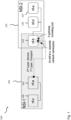
- figure 1 illustrates a high-level architecture of a communication network 100 illustrating inter-slice sharing concepts implemented by implementations of the disclosure.
- the communication network 100 is a 5G network.
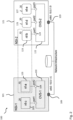
- the communication network 100 shown in figure 1 comprise two network slices or slices instances 101 and 121, referred to as NSI-1 and NSI-2. These two NSIs 102, 121 are isolated and invisible to each other in the sense that in both of these individual NSIs 102, 121 network functions (NFs), such as the NFs 103, 105, 123, 125 and 127 shown in figures 1 and 2 , have their own private network addresses and are interconnected by provisioned and private virtual links.
- NFs network functions
- one or multiple NFs of an NSI 101, 121 may be instantiated on the same host node so that those NFs may share the same interface for communications.
- the interface shared by the NFs can be referred to as a communication entity, in particular a virtual switch or gateway. More specifically, the virtual switch here is not the gateway of the whole NSI but an architecture view in virtualization. Alternatively, an NSI 101, 121 may not have a common gateway but a logical (virtual) private network, where any node of the private network can have a gateway to access the external world.
- implementations of the disclosure provide solutions to a unidirectional point-to-point inter-slice sharing problem where an NF (e.g. nf-b 123) from NSI-2 121 will have to be shared with an NF (e.g. nf-a 103) in NSI-1 101.
- the "unidirectional" requirement here means that NSI-2:nf-b, i.e. the NF nf-b 123 of NSI-2 121, is shared with NSI-1 only, while no NF from NSI-1 101 will be part of, i.e. shared with NSI-2 121.
- the two interested or target NFs 103, 123 are hosted on different nodes, i.e. each of them is associated with its own communication entity, i.e. virtual switch or gateway, namely NSI-1:gw 102 and NSI-2:gw 122, respectively.
- the two NSIs 101, 121 can have the same private network address domain.
- every NF has an IP address from 192.168.10.x subnet.
- implementations of the disclosure make use of a dedicated network namespace so that an interface inside of the namespace can have an overlapping address.
- NSI-2:nf-b 123 will create a new network namespace called ns:nf-b:NSI-1, preserved for inter-slice sharing with NSI-1:nf-a 103.
- a local network pipe with two endpoints (interfaces) 126, 128 is created at the local host node.
- the main purpose of the local path with the endpoints 126, 128 is to move to the dedicated network namespace (i.e. ns:nf-b:NSI-1) so that it becomes invisible to its current NSI domain and avoids address conflicts with other NFs.
- a network device such as a network management device or entity, is configured to operate the network function 123 of the first network slice NSI-2 121, wherein the network device is configured to establish an end-to-end isolated path from the network function 123 of NSI-2 121 to the network function 103 of NSI-1.
- the network device can be a management layer entity, which can be implemented in various ways.
- a management entity could be logically centralized management layer entity. It could also be implemented using a multi-controller realization.
- NSI-2 121 defines a first network namespace and NSI-2 101 defines a second network namespace, wherein the network device is configured to provide a first interface 126, 128 in NSI-2 121 in a third network namespace for establishing the end-to-end isolated path from NF1 123 of NSI-2 121 to NF2 103 of NSI-1 101.
- NSI-2 121 comprises the first communication entity, in particular virtual switch 122 in the first network namespace, wherein the network function 123 is connected with the first communication entity, in particular virtual switch 122 by a second interface, in particular port 124, wherein NSI-1 101 comprises the second communication entity, in particular virtual switch 102 in the second network namespace and wherein the network function 103 is connected with the second communication entity, in particular virtual switch 102 by a third interface, in particular port 104, wherein the network device is configured to provide the first interface, in particular two ports 126, 128, between the network function 123 and the first communication entity, in particular virtual switch 122 in the third network namespace different to the first network namespace and the second network namespace for establishing at least a portion of the end-to-end isolated path from the network function 123 of NSI-2 121 to the network function 103 of NSI-1 101.
- the network management device is configured to provide the first interface, in particular the ports 126, 128 in the third network namespace between the network function 123 and the first communication entity, in particular virtual switch 122 by providing the ports 126, 128 between the network function 123 and the first communication entity, in particular virtual switch 122 in the first network namespace and assigning the ports 126, 128 to the third network namespace.
- the next step implemented by implementations of the disclosure is to interconnect the target or interested NF (i.e. NSI-2:nf-b 123) with the NF 103 in the other NSI (i.e. NSI-1:nf-a 103).
- the IP addresses of the two hosts can be in different domains as well, but routing capability can be assumed between the two hosts.
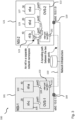
- the path 110 is a tunneling path 110, which can mimic a LAN visibility for the two NFs 103, 123. More specifically, as already mentioned above, two tunneling ports 111, 131 can be created on the two communication entities, e.g. virtual switches 102, 122, respectively.
- the network management device is further configured to provide the communication tunnel 110 from the first communication tunnel port 131 of the first communication entity, in particular virtual switch 122 to the second communication tunnel port 111 of the second communication entity, in particular virtual switch 102.
- the two tunneling ports 111, 131 can be vxlan tunneling ports 111, 131. If Open Virtual Switch (OVS) is used for providing the communication entities 102, 122 implemented as virtual switches 102, 122, the tunneling path 110 can be created on the local host by the following commands:
- OVS Open Virtual Switch
- each vxlan port 111, 131 encapsulates and sends local IP packets with the host address.
- the corresponding vxlan port 111, 131 decapsulates the received packet header and forwards to corresponding receivers by using original private addresses, as illustrated in figure 3 .
- implementations of the disclosure configure forwarding policies 113, 133 implemented on the respective communication entities, in particular virtual switches 102, 122 and link the interested NF 123 to the created tunneling port 131.
- a local network pipe with the endpoints 126, 128 links the NF 123 to the communication entity, in particular virtual switch 122 (and one endpoint of the pipe link has a separated network namespace).
- forwarding policies 113, 133 are provided and/or configured on the communication entities, in particular virtual switches 102, 122 for establishing the last piece of the E2E path between the NFs 103, 123.
- the network management device is further configured to provide and/or adjust the one or more forwarding rules or policies 133 defined in a forwarding table of the first communication entity, in particular virtual switch 122 and/or one or more forwarding rules or policies 113 defined in a forwarding table of the second communication entity, in particular virtual switch 102.
- the network management device is configured to adjust the one or more forwarding rules 133 of the forwarding table of the first communication entity, in particular virtual switch 122 in such a way that a data packet received by the first communication entity, in particular virtual switch 122 from the network function 123 via the two ports 126, 128 is forwarded to the first communication tunnel port 131.
- the network management device is configured to adjust the one or more forwarding rules 113 of the forwarding table of the second communication entity, in particular virtual switch 102 in such a way that a data packet received by the second communication entity, in particular virtual switch 102 from the second communication tunnel port 111 is forwarded to the network function 103.
- the forwarding policies 113, 133 can be as follows: Concerning the communication entity, in particular virtual switch 122 of NSI-2 121, for all packets, which are received from NSI-2:nf-b 123 (i.e. via port4 128 in the figures) and supposed to be shared with NSI-1:nf-a 103, the communiation entity, in particular virtual switch 122 is configured to tag the packets with an NSI identifier (i.e. an identifier of NSI-1 101 in this case) and forward these to the vxlan port 131. For all packets received from the vxlan port 131 (i.e. coming via the tunneling path 110 from NSI-1:nf-a 103), the vxlan port 131 decapsulates these packets and forwards the same to port4 128, in case their destination address is NSI-2:nf-b 123.
- an NSI identifier i.e. an identifier of NSI-1 101 in this case
- those forwarding policies 133 can be translated into the following forwarding rules of a forwarding or flow table:
- NSI-2:nf-b 123 is shared with NSI-1 101, in particular NSI-1:nf-a 103 only. This is because, NSI-2:nf-b 123 has been assigned a legal address in NSI-1 101 and it is directly linked to NSI-1 101 through the new interface (in a dedicated network namespace), the vxlan port 131 as well as the new forwarding rules 133.
- implementations of the disclosure add corresponding forwarding rules to allow data traffic going through.
- no NF originally from NSI-1 101 is aware of NSI-2 121 still.
- the above configuration procedures can be used as an atomic procedure so that more complex scenarios can be composed.
- an NSI such as the NSIs 101, 121 illustrated in the figures
- the inter-slice sharing scenario can go far beyond the best-effort transport layer interconnectivity.
- certain types of requirements can still be related to the transport layer, such as bandwidth and latency.
- other types of requirements are often related to the business service flow, such as mutual authentications, certificate exchange and policy control.
- These different types of requirements can be handled by the network slice management plane, in particular an entity 140 illustrated in figure 5 . More specifically, the network slice management plane 140 can be implemented to realize the different requirements across multiple NSIs.
- this interface can be either a dedicated management port of each NSI 101, 121, or can reuse an existing data plane interface, depending on the implementation of the management plane channel.
- these configurations can be applied. This can happen at the newly added interfaces 126, 128 and/or the communication entities, in particular virtual switches 102, 122, looking for an appropriate path for the inter-slice sharing, and even possible adjustments on the deployed NSIs 101, 121, if necessary, as illustrated in figure 5 .
- service layer considerations are not implemented as a one-shot configuration, but rather using a feedback loop procedure, which constantly checks whether any requirement cannot be met.
- the network management device is further configured to perform one or more transport layer adjustments on the basis of one or more service layer requirements, wherein the one or more transport layer adjustments can include adjusting the one or both of the two ports 126, 128 providing the first interface, adjusting one or more of the forwarding rules 133 defined in the forwarding table of the first communication entity, in particular virtual switch 122, adjusting one or more of the forwarding rules 113 defined by the forwarding table of the second communication entity, in particular virtual switch 102, and/or adjusting the communication tunnel 110, such as the hops, from the first communication tunnel port 131 of the first communication entity, in particular virtual switch 122 to the second communication tunnel port 111 of the second communication entity, in particular virtual switch 102.
- the one or more transport layer adjustments can include adjusting the one or both of the two ports 126, 128 providing the first interface, adjusting one or more of the forwarding rules 133 defined in the forwarding table of the first communication entity, in particular virtual switch 122, adjusting one or more of the forwarding rules 113 defined by the forward
- the disclosed system, apparatus, and method may be implemented in other manners.
- the described apparatus implementation is merely exemplary.
- the unit division is merely logical function division and may be other division in actual implementation.
- a plurality of units or components may be combined or integrated into another system, or some features may be ignored or not performed.
- the displayed or discussed mutual couplings or direct couplings or communication connections may be implemented by using some interfaces.
- the indirect couplings or communication connections between the apparatuses or units may be implemented in electronic, mechanical, or other forms.
- the units described as separate parts may or may not be physically separate, and parts displayed as units may or may not be physical units, may be located in one position, or may be distributed on a plurality of network units. Some or all of the units may be selected according to actual needs to achieve the objectives of the solutions of the implementations.
Landscapes
- Engineering & Computer Science (AREA)
- Computer Networks & Wireless Communication (AREA)
- Signal Processing (AREA)
- Software Systems (AREA)
- Theoretical Computer Science (AREA)
- Physics & Mathematics (AREA)
- General Engineering & Computer Science (AREA)
- General Physics & Mathematics (AREA)
- Data Exchanges In Wide-Area Networks (AREA)
Description
- Generally, the present disclosure relates to the field of telecommunications. More specifically, the present disclosure relates to devices, systems and methods for inter-slice sharing in communication networks, in particular 5G core networks.
- The next generation of mobile networks, i.e. 5G networks, is expected to support many new types of services and connections between various devices such as cars, wearables, sensors and actuators from both private and industrial environments. The new types of services and connections usually imply very distinct service requests on latency, data rate and so on, which naturally ask for different treatments and thereby pose challenges to the control of 5G networks.
- In particular, supporting various new types of services has a deep impact on the core network architecture. In today's mobile networks, services mainly refer to the access of portable devices in human hands for data and voice services only. Core networks can apply basically the same treatment to portable devices following the best-effort principle. Hence, those services are predictable and how to respond them can be well preplanned. With various new service requests, however, service patterns will become quite heterogeneous. Consequently, service requests to a 5G network are difficult to predict. A proper way to meet the requirements is to agilely respond to any incoming services in a dynamic way.
- Efficiently responding to distinct and unpredictable service requests is not an easy task. Administratively pre-planning approaches with static network deployment do not work. Recently, Software-Defined Networking (SDN) and Network Function Virtualization (NFV) have been proposed as the two key enablers to realize a flexible and programmable network infrastructure. The idea behind SDN is to abstract everything as a flow and to move the complexity of flow treatment to a logically centralized element called SDN Controller (SDNC). Hence, the SDN view reduces all network elements to "dumb" flow treatment devices, which are only responsible for flow processing. With these concepts, SDN fuses all management and control plane (CP) intelligence at the SDNC. In return, the common abstraction and the locally available data simplify the development of network control and management applications. NFV further turns existing network functions, which were mainly implemented by dedicated and specialized hardware before, into virtualized function modules that can be easily deployed or removed as needed.
- With this two enabling technologies, responding to new service requests becomes much easier than before given that any network functions (NFs) can be deployed/allocated on-demand (NFV's features) and forwarding behaviors of them can be remotely programmed (SDN's features), just like installing and running a computer program.
- In the upcoming 5G era, services provided via mobile networks will not be limited to human communications and basic internet connections. Rather, it is expected that there will be an increasingly large number of services of vertical industries that will be provided through the wireless mobile network. The legacy best-effort quality-of-service (QoS) is however incapable of supporting heterogeneous services. For example, an ultra-low latency connectivity is required by eHealth services if a medical robot has to be precisely operated in real time for remote surgery. Another example is that a virtual reality (VR) live broadcast will need high throughput bandwidth and meanwhile low latency interactions in order to provide immersive entertainment experiences. Hence, 5G networks will have to guarantee various service level agreements (SLAs) for different customers but share the same physical infrastructure.
- An approach to meet these different requirements is, firstly, a virtualization of the physical infrastructure as clouds using the SDN and NFV technologies mentioned above, whereby the physical infrastructure is converted to be fully programmable. Secondly, resource isolations are emphasized in order to provide performance guarantees. These two proposals generate a new technical concept, called network slicing, where multiple network tenants will have their own network resources that are isolated from each other and SLA-guaranteed. Such a portion of isolated network resources for one tenant is a virtualized logical network accommodated in the shared infrastructure, called a network slice instance (NSI). Highlighted as a key technology, in an NSI, its configurations and features (called slice type) are customized for particular customers. According to the current 3GPP SA2 definitions, an NSI is an end-to-end networking capability for providing services.
- In addition to highlighting features on customizations and resource isolations of the forthcoming network slicing technology, inter-slice sharing has been proposed, which poses technical challenges while is less considered so far. According to a current 3GPP definition, inter-slice sharing shall support two sharing cases. The first case is that a specific network function (NF) within one NSI can be shared with or used by another NSI. The second case is that a subset of an NSI can be shared or used to compose another NSI. Note that the latter case is a generalized case of the former one because a subset of an NSI includes multiple NFs. However, such a feature/functionality contradicts the spirit of slicing the network. In other words, slicing network resource advocates to split resources, rather than to share. This introduces a technical challenge for network slicing technology. Since network slicing technology is still in development and carrier grade solutions do not exist, two possible candidates have been proposed as the solution for inter-slice sharing.
- The first solution is from 3GPP technical specifications. In 3GPP SA2, a service-based architecture (SBA) is proposed as the main architectural framework for the coming 5G. Different from the previous generations, SBA defines a modularized service model where NF communications happen over a service-based interface (SBI) bus, instead of dedicated point-to-point wired connections between hardware devices. The SBI bus decouples NFs and reference points that every NF has to associate. Based on SBA/SBI bus, network services can be provided via NF composition by chaining any required NFs. One NF instance can be shared and associated with other NFs. Although NF sharing is supported, it is unclear how the SBA/SBI bus will support inter-slice NF sharing where NFs belonging to different NSls should not be visible as normal NFs.
- Given a virtualized environment settings, it is natural to think whether existing solutions from cloud computing can be used. Virtual private cloud (VPC) peering proposed for interconnecting two virtual data centers seems to be an appropriate choice. A cloud resource provider provision computing resource in the cloud datacenter based on the request of a tenant. The provisioned resource is logically dedicated for that particular tenant and it is guaranteed according to the submitted order from the tenant, which is similar to network slicing scenario. Such a portion of provisioned resource is called as a VPC. In cloud infrastructure, one tenant may have multiple VPC instances, where they may be deployed in the same datacenter or geographically across different datacenters. In either case, the tenant may want its VPCs can form a whole private network that communicate with each other (e.g. private IP addressing). Therefore, the cloud infrastructure has to be able to establish such kind of interconnections, which is called VPC peering. However, as will be explained in more detail below, VPC peering cannot be trivially used as a solution for inter-slice sharing. First of all, VPC peering does not support overlapped addresses in the peered VPCs. Overlapped addresses can be avoided when planning, but peering two NSIs may not be able to plan when requesting the two NSIs. In other words, it is possible that initially the two NSIs were planned individually (thus possibly having overlapped private addresses on individual NSIs), and due to later on requirement, we have to peer the two NSIs. In this case, completely re-allocating addresses will be difficult because this may suspend and will have to stop the running services.
- Secondly, between two VPCs, only one peering connection is supported. VPC peering is more like a routing table modification at the cloud datacenter layer. When a VPC is created, it is always connected to a gateway router that is either physical or virtual. If a VPC needs to access external, the gateway is configured to behave as a NAT, otherwise all traffics are internally routable. When VPC peering is needed, on the two gateway nodes, routing policies will be modified so that the traffic from either VPC can get through. If necessary, a direct path can be established as well. However, in current cloud platforms, only one such a connection can be established, and in case of a partial visibility (e.g. some VMs should be still private), security policies have to be added, because, otherwise, two VPCs are connected as one domain. This, however, cannot fulfill the inter-slice NF sharing requirement.
- Thus, there is still a need for devices, systems and methods for providing inter-slice NF sharing, in particular in 5G core networks.
-
US 2018/077023 relates to method and apparatus for network slicing. - The invention has been defined in the independent claims. Further specific technical features have been defined in the dependent claims.
- Generally, implementations of the disclosure provide a new interconnectivity technique for inter-slice sharing scenarios, which provide for point-to-point sharing when needed, while preserving slice isolation.
- Comparing with existing peering techniques (i.e. SBI Bus and VPC peering), implementations of the disclosure not only push to a finer interconnecting granularity, but also take service layer requirements into considerations in addition to basic transport layer connectivity, thereby offering a two-layer interconnecting scheme. Implementations of the disclosure preserve the isolation where network interfaces will be created in dedicated networking namespaces, tunneling ports will be created at NSI gateway nodes, and the new interface and the tunneling port will be linked together so as to establish an end-to-end (E2E) path between target entities. According to implementations of the disclosure isolation at the service layer is met by adding rules when building the E2E path at the transport layer. Based on the atomic inter-slice sharing operations implemented by implementations of the disclosure, complex sharing scenarios (e.g. sub-slice sharing) can be composed as well. With smart implementation strategies implementations of the disclosure can be implemented in a very efficient way.
- Details of one or more implementations are set forth in the accompanying drawings and the description below. Other features, objects, and advantages will be apparent from the description, drawings, and claims.
- In the following implementations of the disclosure are described in more detail with reference to the attached figures and drawings, in which:
- Fig. 1
- is a high-level block diagram of a network architecture illustrating inter-slice sharing concepts implemented by implementations of the disclosure;
- Fig. 2
- is a block diagram showing a network architecture for implementing inter-slice sharing concepts according to implementations of the disclosure;
- Fig. 3
- is a block diagram showing the network architecture of
figure 2 further including interfaces and a tunneling path implementing inter-slice sharing concepts according to implementations of the disclosure; - Fig. 4
- is a block diagram showing the network architecture of
figure 3 further including flow rule configuration tables implementing inter-slice sharing concepts according to implementations of the disclosure; and - Fig. 5
- is a block diagram showing the network architecture of
figure 4 further including a management entity for service layer policy control according to implementations of the disclosure. - In the following identical reference signs refer to identical or at least functionally equivalent features.
- To make the objectives, technical solutions, and advantages of this invention clearer, the following further describes various implementations in detail with reference to the accompanying drawings. The implementations described below are not all claimed, they are included to help understanding the context of the invention. While the description refers to various implementations, the embodiments of the invention are those which comprise at least all the features of an independent claim. Any implementation which does not fall within the scope of the claims does not form part of the invention, but rather included as an illustrative example that is useful for understanding the invention.
- In the following description, reference is made to the accompanying figures, which form part of the disclosure, and which show, by way of illustration, specific aspects of implementations of the disclosure or specific aspects in which implementations of the present disclosure may be used. It is understood that implementations of the disclosure may be used in other aspects and comprise structural or logical changes not depicted in the figures.
- For instance, it is understood that a disclosure in connection with a described method may also hold true for a corresponding device or system configured to perform the method and vice versa. For example, if one or a plurality of specific method steps are described, a corresponding device may include one or a plurality of units, e.g. functional units, to perform the described one or plurality of method steps (e.g. one unit performing the one or plurality of steps, or a plurality of units each performing one or more of the plurality of steps), even if such one or more units are not explicitly described or illustrated in the figures. On the other hand, for example, if a specific apparatus is described based on one or a plurality of units, e.g. functional units, a corresponding method may include one step to perform the functionality of the one or plurality of units (e.g. one step performing the functionality of the one or plurality of units, or a plurality of steps each performing the functionality of one or more of the plurality of units), even if such one or plurality of steps are not explicitly described or illustrated in the figures. Further, it is understood that the features of the various exemplary implementations and/or aspects described herein may be combined with each other, unless specifically noted otherwise.
- As will be described in more detail further below, implementations of the disclosure provide devices, systems and methods for implementing inter-slice peering communications, i.e. inter-slice sharing. Implementations of the disclosure provide solutions to two conflicting goals, where, on the one hand, such an inter-slice sharing (or peering) should be fine-grained and flexible enough and, on the other hand, the isolation of individual network slice instances (NSIs) is still preserved. Furthermore, implementations of the disclosure provide for service layer peering, where even if inter-slice transport layer communication is possible, a specific service requirement is also taken care of. As will be appreciated from the following detailed description, implementations of the disclosure can be easily deployed and automatized without introducing complex human interventions. In the following implementations of the disclosure will be described in a bottom-up manner.
- Generally, at the level of the transport layer implementations of the disclosure are based on the following ideas for handling inter-slice transport layer sharing. Since an NSI is a logically isolated resource, any NF of the NSI is also isolated from and invisible to the external world. In order to peer two NFs contained in two different NSIs, implementations of the disclosure establish a path, which is isolated as well. Implementations of the disclosure create an end-to-end (E2E) path consisting of newly added interfaces and necessary tunneling connections between the two NSIs. According to implementations of the disclosure those additional interfaces, in particular ports, will be in a separate network namespace, which is invisible to the other NFs in the NSI the target NF is located in. Moreover, implementations of the disclosure do not make the two NSIs fully visible to each other. Instead, according to implementations of the disclosure special tunneling ports will be created on the gateway nodes where the NSI is NATed to the external world, and the special tunneling ports will link to the corresponding interfaces added on the target NF. Moreover, according to implementations of the disclosure such a respective tunneling port will take QoS requirements into considerations, in order to fulfill the inter-slice sharing service level agreements (SLAs). According to implementations of the disclosure, such a path can be unidirectional if the new interfaces and/or the tunneling ports are configured to be unidirectional.
- At the level of the service layer implementations of the disclosure are based on the following ideas for handling inter-slice service layer connectivity. Based on the connectivity provided by the transport layer, NFs in two different NSIs can send and receive messages between each other. At the service layer, such a communication capability will be further refined if particular restrictions are defined. Restrictions normally interpret the requirements from concrete business procedures. For the connected two NFs at two NSIs, a possible implementation is that though the two NFs can exchange information, only one of them is allowed to further propagate the received/observed information, while the other NF is the last consumer. According to implementations of the disclosure these restrictions can be realized when creating the new interfaces, where special rules will be added.
- More specifically,
figure 1 illustrates a high-level architecture of acommunication network 100 illustrating inter-slice sharing concepts implemented by implementations of the disclosure. With the two-layer considerations for inter-slice sharing mentioned above communications between any specific NFs are under full control. Additionally, based on this atomic operations, more complicated scenarios can be composed, thus fulfilling any possible combinations of NF or sub-slice NFs sharing. In an implementation, thecommunication network 100 is a 5G network. - The
communication network 100 shown infigure 1 comprise two network slices orslices instances NSIs individual NSIs NFs figures 1 and2 , have their own private network addresses and are interconnected by provisioned and private virtual links. In an implementation, one or multiple NFs of anNSI NSI - Under further reference to
figure 2 , implementations of the disclosure provide solutions to a unidirectional point-to-point inter-slice sharing problem where an NF (e.g. nf-b 123) from NSI-2 121 will have to be shared with an NF (e.g. nf-a 103) in NSI-1 101. The "unidirectional" requirement here means that NSI-2:nf-b, i.e. the NF nf-b 123 of NSI-2 121, is shared with NSI-1 only, while no NF from NSI-1 101 will be part of, i.e. shared with NSI-2 121. In order to avoid trivial cases, it is assumed that the two interested or targetNFs gw 102 and NSI-2:gw 122, respectively. In an implementation, the twoNSIs figure 1 , every NF has an IP address from 192.168.10.x subnet. This illustrates one key difference to the conventional VPC peering scenario, where the peered VPCs must have non-overlapping addresses, which requires substantial pre-planning. Nevertheless, a conventional VPC peering solution cannot be applied in this case, because it causes address re-allocation for the deployedNSIs - For providing inter-slice sharing at the transport layer, while keeping the respective addresses unchanged, implementations of the disclosure make use of a dedicated network namespace so that an interface inside of the namespace can have an overlapping address. As shown in the exemplary implementations of
figures 1 and2 and under further reference tofigure 3 , NSI-2:nf-b 123 will create a new network namespace called ns:nf-b:NSI-1, preserved for inter-slice sharing with NSI-1:nf-a 103. Thereafter, in an implementation, a local network pipe with two endpoints (interfaces) 126, 128 is created at the local host node. For one endpoint, it is added to anew port 128 created on the communication entity, in particular virtual switch orgateway 122, and for the other endpoint, it is assigned with an IP address that is legal in the domain of NSI-1 101. According to implementations of the disclosure, the main purpose of the local path with theendpoints - Thus, a network device, such as a network management device or entity, is configured to operate the
network function 123 of the first network slice NSI-2 121, wherein the network device is configured to establish an end-to-end isolated path from thenetwork function 123 of NSI-2 121 to thenetwork function 103 of NSI-1. In an implementation, the network device can be a management layer entity, which can be implemented in various ways. For example, such a management entity could be logically centralized management layer entity. It could also be implemented using a multi-controller realization. - As already described above, in an implementation, NSI-2 121 defines a first network namespace and NSI-2 101 defines a second network namespace, wherein the network device is configured to provide a
first interface NF1 123 of NSI-2 121 toNF2 103 of NSI-1 101. - In an implementation, NSI-2 121 comprises the first communication entity, in particular
virtual switch 122 in the first network namespace, wherein thenetwork function 123 is connected with the first communication entity, in particularvirtual switch 122 by a second interface, inparticular port 124, wherein NSI-1 101 comprises the second communication entity, in particularvirtual switch 102 in the second network namespace and wherein thenetwork function 103 is connected with the second communication entity, in particularvirtual switch 102 by a third interface, inparticular port 104, wherein the network device is configured to provide the first interface, in particular twoports network function 123 and the first communication entity, in particularvirtual switch 122 in the third network namespace different to the first network namespace and the second network namespace for establishing at least a portion of the end-to-end isolated path from thenetwork function 123 of NSI-2 121 to thenetwork function 103 of NSI-1 101. - In an implementation, the network management device is configured to provide the first interface, in particular the
ports network function 123 and the first communication entity, in particularvirtual switch 122 by providing theports network function 123 and the first communication entity, in particularvirtual switch 122 in the first network namespace and assigning theports - After creating the local link and assigning addresses, the next step implemented by implementations of the disclosure is to interconnect the target or interested NF (i.e. NSI-2:nf-b 123) with the
NF 103 in the other NSI (i.e. NSI-1:nf-a 103). Technically, this requires having adedicated path 110 between two host nodes. In the exemplary implementation shown in the figures, NSI-1:nf-a 103 is hosted on anode 109 with its IP address H1=10.0.1.5 and NSI-2:nf-b 123 is hosted on anode 129 with its IP address H2=10.0.1.9. According to implementations of the disclosure, the IP addresses of the two hosts can be in different domains as well, but routing capability can be assumed between the two hosts. According to an implementation, thepath 110 is atunneling path 110, which can mimic a LAN visibility for the twoNFs ports virtual switches - Thus, in an implementation, the network management device is further configured to provide the
communication tunnel 110 from the firstcommunication tunnel port 131 of the first communication entity, in particularvirtual switch 122 to the secondcommunication tunnel port 111 of the second communication entity, in particularvirtual switch 102. - In an implementation, the two tunneling
ports vxlan tunneling ports communication entities virtual switches tunneling path 110 can be created on the local host by the following commands:
# for NSI-1:gw 102:
$ ovs-vsctl add-port OVS-1 vxlan --set interface vxlan type=vxlan options:remote_ip=10.0.1.9,
options:key=flow options:dst_port=8472
# for NSI-2:gw 122:
$ ovs-vsctl add-port OVS-2 vxlan --set interface vxlan type=vxlan options:remote_ip=10.0.1.5,
options:key=flow options:dst_port=8472
Concerning the communication entity, in particular
- table=0, in_port=4, actions=set_field:NSI-1->tun_id, resubmit(,1)
- table=0, resubmit(,1)
- table=1, tun_id=NSI-1, ip_dst=192.168.10.40, action=output:4
- table=1, tun_id=NSI-1, ip_dst=192.168.10.10, actions=output:vxlan
- table=0, in_port=1, actions=set_field:NSI-1->tun_id, resubmit(,1)
- table=0, resubmit(,1)
- table=1, tun_id=NSI-1, ip_dst=192.168.10.10, action=output:1
- table=1, tun_id=NSI-1, ip_dst=192.168.10.40, action=output:vxlan
Claims (13)
- A network device configured to operate a network function, NF1, (123) of a first network slice, NSI-2 (121), wherein the network device is configured to establish an end-to-end path from NF1 (123) of NSI-2 (121) to a network function, NF2, (103) of a second network slice, NSI-1 (101), the network device being characterised by:the network device is configured to provide a first interface (126, 128) in NSI-2 (121) in a third network namespace between NF1 (123) and a first communication entity;wherein, NSI-2 defines a first network namespace in NSI-2 and NSI-1 defines a second network namespace, wherein NSI-2 (121) comprises the first communication entity in the first network namespace and wherein NF1 (123) is connected with the first communication entity by a second interface (124), wherein NSI-1 (101) comprises a second communication entity in the second network namespace and wherein NF2 (103) is connected with the second communication entity by a third interface (104);the network device is further configured to provide a communication tunnel (110) between NSI-2 (121) and NSI-1 (101), whereby the network device is configured to provide the communication tunnel (110) from a first communication tunnel port (131) of a first communication entity NSI-2 (121) to a second communication tunnel port (111) of a second communication entity; andthe network device is configured to provide and/or adjust one or more forwarding rules in NSI-2 (121) and/or one or more forwarding rules in NSI-1 (101).
- The network device of claim 1, wherein the network device is configured to provide the first interface (126, 128) in the third network namespace between NF1 (123) and the first communication entity, in particular virtual switch (122) by providing the first interface (126, 128) between NF1 (123) and the first communication entity, in particular virtual switch (122) in the first network namespace and assigning the first interface (126, 128) to the third network namespace.
- The network device of claim 1 or 2, wherein the network device is configured to provide the first interface (126, 128) in the third network namespace between NF1 (123) and the first communication entity, in particular virtual switch (122) by further providing a port (128) for NF1 (123) on the first communication entity, in particular virtual switch (122).
- The network device of claim 3, wherein the network device is configured to provide the first communication tunnel port (131) such that the first communication tunnel port (131) is configured to encapsulate and send packets with a host address to the second communication tunnel port (111).
- The network device of claim 3 or 4, wherein the network device is configured to provide the second communication tunnel port (111) such that the second communication tunnel port (111) is configured to decapsulate packets received from the first communication tunnel port (131).
- The network device of claim 1, wherein the network device is further configured to provide and/or adjust the one or more forwarding rules (133) of a forwarding table of a first communication entity, in particular virtual switch (122) of NSI-2 (121) and/or the one or more forwarding rules (113) of a forwarding table of a second communication entity, in particular virtual switch (102) of NSI-1 (101).
- The network device of claim 6, wherein the network device is configured to provide and/or adjust the one or more forwarding rules (133) of the forwarding table of the first communication entity, in particular virtual switch (122) in such a way that a packet received by the first communication entity, in particular virtual switch (122) from NF1 (123) via a first interface (126, 128) between NF1 (123) and the first communication entity, in particular virtual switch (122) is forwarded to a first communication tunnel port (131) of the first communication entity, in particular virtual switch (122).
- The network device of claim 6 or 7, wherein the network device is configured to provide and/or adjust the one or more forwarding rules (113) of the forwarding table of the second communication entity, in particular virtual switch (102) in such a way that a packet received by the second communication entity, in particular virtual switch (102) from a second communication tunnel port (111) of the second communication entity, in particular virtual switch (102) is forwarded to NF2 (103).
- The network device of any one of the preceding claims, wherein the network device is further configured to perform one or more transport layer adjustments on the basis of one or more service layer requirements for establishing the end-to-end isolated path from NF1 (123) of NSI-2 (121) to NF2 (103) of NSI-1 (101);
wherein the one or more transport layer adjustments include adjusting a first interface (126, 128) between NF1 (123) and a first communication entity, in particular virtual switch (122) of NSI-2 (121), one or more forwarding rules (133) of a forwarding table of the first communication entity, in particular virtual switch (122), one or more forwarding rules (113) of a forwarding table of a second communication entity, in particular virtual switch (102) of NSI-1 (101), and/or a communication tunnel (110) from a first communication tunnel port (131) of the first communication entity, in particular virtual switch (122) to a second communication tunnel port (111) of the second communication entity, in particular virtual switch (102). - A method of operating a network function, NF1, (123) of a first network slice, NSI-2, (121), wherein the method comprises the step of establishing an end-to-end path from NF1 (123) of NSI-2 (121) to a network function, NF2, (103) of a second network slice, NSI-1 (101), the method being performed by a network device and being characterised in that it comprises:providing a first interface (126, 128) in NSI-2 (121) in a third network namespace between NF1(123) and a first communication entity;wherein, NSI-2 defines a first network namespace in NSI-2 and NSI-1 defines a second network namespace, wherein NSI-2 (121) comprises the first communication entity in the first network namespace and wherein NF1 (123) is connected with the first communication entity by a second interface (124), wherein NSI-1 (101) comprises a second communication entity in the second network namespace and wherein NF2 (103) is connected with the second communication entity by a third interface (104);providing a communication tunnel (110) between NSI-2 (121) and NSI-1 (101), comprises: providing the communication tunnel (110) from a first communication tunnel port (131) of a first communication entity NSI-2 (121) to a second communication tunnel port (111) of a second communication entity; andproviding and/or adjusting one or more forwarding rules in NSI-2 (121) and/or one or more forwarding rules in NSI-1 (101).
- The method of claim 10, wherein the method further comprises:
providing and/or adjusting the one or more forwarding rules (133) of a forwarding table of a first communication entity, in particular virtual switch (122) of NSI-2 (121) and/or the one or more forwarding rules (113) of a forwarding table of a second communication entity, in particular virtual switch (102) of NSI-1 (101). - The network device of claim 11, wherein providing and/or adjusting the one or more forwarding rules (133) of the forwarding table of the first communication entity comprises: providing and/or adjusting the one or more forwarding rules (133) of the forwarding table of the first communication entity in such a way that a packet received by the first communication entity, in particular virtual switch (122) from NF1 (123) via a first interface (126, 128) between NF1 (123) and the first communication entity, in particular virtual switch (122) is forwarded to a first communication tunnel port (131) of the first communication entity, in particular virtual switch (122).
- A communication network (100) comprising:a first network slice, NSI-2, (121) with a network function, NF1, (123);a second network slice, NSI-1, (101) with a network function, NF2, (103); andthe network device of any one of claims 1 to 9.
Applications Claiming Priority (1)
| Application Number | Priority Date | Filing Date | Title |
|---|---|---|---|
| PCT/EP2018/073142 WO2020043275A1 (en) | 2018-08-28 | 2018-08-28 | Inter-slice sharing in 5g core networks |
Publications (2)
| Publication Number | Publication Date |
|---|---|
| EP3834379A1 EP3834379A1 (en) | 2021-06-16 |
| EP3834379B1 true EP3834379B1 (en) | 2023-07-12 |
Family
ID=63557414
Family Applications (1)
| Application Number | Title | Priority Date | Filing Date |
|---|---|---|---|
| EP18769070.6A Active EP3834379B1 (en) | 2018-08-28 | 2018-08-28 | Inter-slice sharing in 5g core networks |
Country Status (4)
| Country | Link |
|---|---|
| US (1) | US12069559B2 (en) |
| EP (1) | EP3834379B1 (en) |
| CN (1) | CN112602292B (en) |
| WO (1) | WO2020043275A1 (en) |
Families Citing this family (8)
| Publication number | Priority date | Publication date | Assignee | Title |
|---|---|---|---|---|
| US11620151B2 (en) * | 2020-09-22 | 2023-04-04 | Red Hat, Inc. | Flow rule installation latency testing in software defined networks |
| CN114666304B (en) * | 2020-12-07 | 2024-11-01 | 中兴通讯股份有限公司 | Message processing, sending method, terminal, communication equipment and computer storage medium |
| US11838273B2 (en) | 2021-03-29 | 2023-12-05 | Amazon Technologies, Inc. | Extending cloud-based virtual private networks to radio-based networks |
| US11411833B1 (en) * | 2021-04-23 | 2022-08-09 | Vmware, Inc. | Methods and apparatus to model and verify a hybrid network |
| CN116527639A (en) * | 2022-01-24 | 2023-08-01 | 华为云计算技术有限公司 | Address space recommending method and device and related equipment |
| CN116155837B (en) * | 2022-11-16 | 2024-07-30 | 天翼云科技有限公司 | A message forwarding method for a virtual switch |
| US20240289157A1 (en) * | 2023-02-23 | 2024-08-29 | VMware LLC | User interface for health monitoring of multi-service system |
| WO2026090951A1 (en) * | 2024-10-30 | 2026-05-07 | 北京小米移动软件有限公司 | Ip address management method and apparatus, device, system, storage medium, and program product |
Family Cites Families (6)
| Publication number | Priority date | Publication date | Assignee | Title |
|---|---|---|---|---|
| US20170164212A1 (en) | 2015-09-29 | 2017-06-08 | Telefonaktiebolaget L M Ericsson (Publ) | Network slice management |
| US10129108B2 (en) | 2015-11-13 | 2018-11-13 | Huawei Technologies Co., Ltd. | System and methods for network management and orchestration for network slicing |
| US10411964B2 (en) * | 2016-09-09 | 2019-09-10 | Huawei Technologies Co., Ltd. | Method and apparatus for network slicing |
| CN108023757B (en) * | 2016-11-03 | 2020-04-28 | 华为技术有限公司 | Method, apparatus and system for managing network slice instances |
| CN108270823B (en) * | 2016-12-30 | 2022-02-22 | 华为技术有限公司 | Service providing method, device and system |
| EP4642084A3 (en) * | 2017-12-08 | 2026-01-14 | Comcast Cable Communications, LLC | User plane function selection for isolated network slice |
-
2018
- 2018-08-28 EP EP18769070.6A patent/EP3834379B1/en active Active
- 2018-08-28 CN CN201880096584.3A patent/CN112602292B/en active Active
- 2018-08-28 WO PCT/EP2018/073142 patent/WO2020043275A1/en not_active Ceased
-
2021
- 2021-02-24 US US17/183,799 patent/US12069559B2/en active Active
Also Published As
| Publication number | Publication date |
|---|---|
| CN112602292A (en) | 2021-04-02 |
| EP3834379A1 (en) | 2021-06-16 |
| CN112602292B (en) | 2022-06-14 |
| US12069559B2 (en) | 2024-08-20 |
| WO2020043275A1 (en) | 2020-03-05 |
| US20210204191A1 (en) | 2021-07-01 |
Similar Documents
| Publication | Publication Date | Title |
|---|---|---|
| US12069559B2 (en) | Inter-slice sharing in 5G core networks | |
| Bakshi | Considerations for software defined networking (SDN): Approaches and use cases | |
| EP3096490B1 (en) | Method for realizing network virtualization and related device and communication system | |
| US10033622B2 (en) | Controller-based dynamic routing in a software defined network environment | |
| JP6477864B2 (en) | Control device, control method and program | |
| EP2806601A1 (en) | Tunnels between virtual machines | |
| CN109155799A (en) | The subnet extension communicated via layer three | |
| WO2016107418A1 (en) | Allocation method, apparatus and system for cloud network communication path | |
| KR20120052981A (en) | Method and system for deploying at least one virtual network on the fly and on demand | |
| WO2016159192A1 (en) | Control device, control method, and program | |
| CN112385194B (en) | Stateful packet transfer between remote networks | |
| CN108574613B (en) | Layer 2 interworking method and device for SDN data center | |
| CN112671811B (en) | Network access method and equipment | |
| CN113039752B (en) | Network node and method for supporting a service-based architecture | |
| CN108965091B (en) | Network element management method and system based on VXLAN tunnel | |
| JP5063726B2 (en) | Configuration control method for virtual node device | |
| WO2016159057A1 (en) | Control device, control method, and program | |
| Šeremet et al. | Evolving IP/MPLS network in order to meet 5G requirements | |
| Kim et al. | SDN-based orchestration for interworking cloud and transport networks | |
| WO2020108772A1 (en) | Cross-region network slicing peering for 5g networks | |
| KR20180105375A (en) | Method for inter-cloud virtual networking over packet optical transport network | |
| LEHOCINE et al. | VINEMA: Towards automated management of virtual networks in SDN infrastructures | |
| EP4274197B1 (en) | Data communication managing component and method for performing guaranteed performance data communication | |
| Granelli et al. | Realizing network slicing | |
| WO2017169947A1 (en) | Operation device, communication system, and update method |
Legal Events
| Date | Code | Title | Description |
|---|---|---|---|
| STAA | Information on the status of an ep patent application or granted ep patent |
Free format text: STATUS: UNKNOWN |
|
| STAA | Information on the status of an ep patent application or granted ep patent |
Free format text: STATUS: THE INTERNATIONAL PUBLICATION HAS BEEN MADE |
|
| PUAI | Public reference made under article 153(3) epc to a published international application that has entered the european phase |
Free format text: ORIGINAL CODE: 0009012 |
|
| STAA | Information on the status of an ep patent application or granted ep patent |
Free format text: STATUS: REQUEST FOR EXAMINATION WAS MADE |
|
| 17P | Request for examination filed |
Effective date: 20210312 |
|
| AK | Designated contracting states |
Kind code of ref document: A1 Designated state(s): AL AT BE BG CH CY CZ DE DK EE ES FI FR GB GR HR HU IE IS IT LI LT LU LV MC MK MT NL NO PL PT RO RS SE SI SK SM TR |
|
| DAV | Request for validation of the european patent (deleted) | ||
| DAX | Request for extension of the european patent (deleted) | ||
| GRAP | Despatch of communication of intention to grant a patent |
Free format text: ORIGINAL CODE: EPIDOSNIGR1 |
|
| STAA | Information on the status of an ep patent application or granted ep patent |
Free format text: STATUS: GRANT OF PATENT IS INTENDED |
|
| RIC1 | Information provided on ipc code assigned before grant |
Ipc: H04W 84/04 20090101ALN20230113BHEP Ipc: H04L 12/46 20060101AFI20230113BHEP |
|
| INTG | Intention to grant announced |
Effective date: 20230214 |
|
| GRAS | Grant fee paid |
Free format text: ORIGINAL CODE: EPIDOSNIGR3 |
|
| GRAA | (expected) grant |
Free format text: ORIGINAL CODE: 0009210 |
|
| STAA | Information on the status of an ep patent application or granted ep patent |
Free format text: STATUS: THE PATENT HAS BEEN GRANTED |
|
| AK | Designated contracting states |
Kind code of ref document: B1 Designated state(s): AL AT BE BG CH CY CZ DE DK EE ES FI FR GB GR HR HU IE IS IT LI LT LU LV MC MK MT NL NO PL PT RO RS SE SI SK SM TR |
|
| REG | Reference to a national code |
Ref country code: CH Ref legal event code: EP |
|
| REG | Reference to a national code |
Ref country code: DE Ref legal event code: R096 Ref document number: 602018053237 Country of ref document: DE |
|
| REG | Reference to a national code |
Ref country code: IE Ref legal event code: FG4D |
|
| P01 | Opt-out of the competence of the unified patent court (upc) registered |
Effective date: 20230727 |
|
| REG | Reference to a national code |
Ref country code: LT Ref legal event code: MG9D |
|
| REG | Reference to a national code |
Ref country code: NL Ref legal event code: MP Effective date: 20230712 |
|
| REG | Reference to a national code |
Ref country code: AT Ref legal event code: MK05 Ref document number: 1588271 Country of ref document: AT Kind code of ref document: T Effective date: 20230712 |
|
| PG25 | Lapsed in a contracting state [announced via postgrant information from national office to epo] |
Ref country code: NL Free format text: LAPSE BECAUSE OF FAILURE TO SUBMIT A TRANSLATION OF THE DESCRIPTION OR TO PAY THE FEE WITHIN THE PRESCRIBED TIME-LIMIT Effective date: 20230712 |
|
| PG25 | Lapsed in a contracting state [announced via postgrant information from national office to epo] |
Ref country code: GR Free format text: LAPSE BECAUSE OF FAILURE TO SUBMIT A TRANSLATION OF THE DESCRIPTION OR TO PAY THE FEE WITHIN THE PRESCRIBED TIME-LIMIT Effective date: 20231013 |
|
| PG25 | Lapsed in a contracting state [announced via postgrant information from national office to epo] |
Ref country code: ES Free format text: LAPSE BECAUSE OF FAILURE TO SUBMIT A TRANSLATION OF THE DESCRIPTION OR TO PAY THE FEE WITHIN THE PRESCRIBED TIME-LIMIT Effective date: 20230712 |
|
| PG25 | Lapsed in a contracting state [announced via postgrant information from national office to epo] |
Ref country code: IS Free format text: LAPSE BECAUSE OF FAILURE TO SUBMIT A TRANSLATION OF THE DESCRIPTION OR TO PAY THE FEE WITHIN THE PRESCRIBED TIME-LIMIT Effective date: 20231112 |
|
| PG25 | Lapsed in a contracting state [announced via postgrant information from national office to epo] |
Ref country code: SE Free format text: LAPSE BECAUSE OF FAILURE TO SUBMIT A TRANSLATION OF THE DESCRIPTION OR TO PAY THE FEE WITHIN THE PRESCRIBED TIME-LIMIT Effective date: 20230712 Ref country code: RS Free format text: LAPSE BECAUSE OF FAILURE TO SUBMIT A TRANSLATION OF THE DESCRIPTION OR TO PAY THE FEE WITHIN THE PRESCRIBED TIME-LIMIT Effective date: 20230712 Ref country code: PT Free format text: LAPSE BECAUSE OF FAILURE TO SUBMIT A TRANSLATION OF THE DESCRIPTION OR TO PAY THE FEE WITHIN THE PRESCRIBED TIME-LIMIT Effective date: 20231113 Ref country code: NO Free format text: LAPSE BECAUSE OF FAILURE TO SUBMIT A TRANSLATION OF THE DESCRIPTION OR TO PAY THE FEE WITHIN THE PRESCRIBED TIME-LIMIT Effective date: 20231012 Ref country code: LV Free format text: LAPSE BECAUSE OF FAILURE TO SUBMIT A TRANSLATION OF THE DESCRIPTION OR TO PAY THE FEE WITHIN THE PRESCRIBED TIME-LIMIT Effective date: 20230712 Ref country code: LT Free format text: LAPSE BECAUSE OF FAILURE TO SUBMIT A TRANSLATION OF THE DESCRIPTION OR TO PAY THE FEE WITHIN THE PRESCRIBED TIME-LIMIT Effective date: 20230712 Ref country code: IS Free format text: LAPSE BECAUSE OF FAILURE TO SUBMIT A TRANSLATION OF THE DESCRIPTION OR TO PAY THE FEE WITHIN THE PRESCRIBED TIME-LIMIT Effective date: 20231112 Ref country code: HR Free format text: LAPSE BECAUSE OF FAILURE TO SUBMIT A TRANSLATION OF THE DESCRIPTION OR TO PAY THE FEE WITHIN THE PRESCRIBED TIME-LIMIT Effective date: 20230712 Ref country code: GR Free format text: LAPSE BECAUSE OF FAILURE TO SUBMIT A TRANSLATION OF THE DESCRIPTION OR TO PAY THE FEE WITHIN THE PRESCRIBED TIME-LIMIT Effective date: 20231013 Ref country code: FI Free format text: LAPSE BECAUSE OF FAILURE TO SUBMIT A TRANSLATION OF THE DESCRIPTION OR TO PAY THE FEE WITHIN THE PRESCRIBED TIME-LIMIT Effective date: 20230712 Ref country code: ES Free format text: LAPSE BECAUSE OF FAILURE TO SUBMIT A TRANSLATION OF THE DESCRIPTION OR TO PAY THE FEE WITHIN THE PRESCRIBED TIME-LIMIT Effective date: 20230712 Ref country code: AT Free format text: LAPSE BECAUSE OF FAILURE TO SUBMIT A TRANSLATION OF THE DESCRIPTION OR TO PAY THE FEE WITHIN THE PRESCRIBED TIME-LIMIT Effective date: 20230712 |
|
| PG25 | Lapsed in a contracting state [announced via postgrant information from national office to epo] |
Ref country code: PL Free format text: LAPSE BECAUSE OF FAILURE TO SUBMIT A TRANSLATION OF THE DESCRIPTION OR TO PAY THE FEE WITHIN THE PRESCRIBED TIME-LIMIT Effective date: 20230712 |
|
| REG | Reference to a national code |
Ref country code: CH Ref legal event code: PL |
|
| REG | Reference to a national code |
Ref country code: DE Ref legal event code: R097 Ref document number: 602018053237 Country of ref document: DE |
|
| PG25 | Lapsed in a contracting state [announced via postgrant information from national office to epo] |
Ref country code: LU Free format text: LAPSE BECAUSE OF NON-PAYMENT OF DUE FEES Effective date: 20230828 |
|
| PG25 | Lapsed in a contracting state [announced via postgrant information from national office to epo] |
Ref country code: SM Free format text: LAPSE BECAUSE OF FAILURE TO SUBMIT A TRANSLATION OF THE DESCRIPTION OR TO PAY THE FEE WITHIN THE PRESCRIBED TIME-LIMIT Effective date: 20230712 Ref country code: RO Free format text: LAPSE BECAUSE OF FAILURE TO SUBMIT A TRANSLATION OF THE DESCRIPTION OR TO PAY THE FEE WITHIN THE PRESCRIBED TIME-LIMIT Effective date: 20230712 Ref country code: LU Free format text: LAPSE BECAUSE OF NON-PAYMENT OF DUE FEES Effective date: 20230828 Ref country code: EE Free format text: LAPSE BECAUSE OF FAILURE TO SUBMIT A TRANSLATION OF THE DESCRIPTION OR TO PAY THE FEE WITHIN THE PRESCRIBED TIME-LIMIT Effective date: 20230712 Ref country code: DK Free format text: LAPSE BECAUSE OF FAILURE TO SUBMIT A TRANSLATION OF THE DESCRIPTION OR TO PAY THE FEE WITHIN THE PRESCRIBED TIME-LIMIT Effective date: 20230712 Ref country code: CZ Free format text: LAPSE BECAUSE OF FAILURE TO SUBMIT A TRANSLATION OF THE DESCRIPTION OR TO PAY THE FEE WITHIN THE PRESCRIBED TIME-LIMIT Effective date: 20230712 Ref country code: SK Free format text: LAPSE BECAUSE OF FAILURE TO SUBMIT A TRANSLATION OF THE DESCRIPTION OR TO PAY THE FEE WITHIN THE PRESCRIBED TIME-LIMIT Effective date: 20230712 Ref country code: MC Free format text: LAPSE BECAUSE OF FAILURE TO SUBMIT A TRANSLATION OF THE DESCRIPTION OR TO PAY THE FEE WITHIN THE PRESCRIBED TIME-LIMIT Effective date: 20230712 Ref country code: CH Free format text: LAPSE BECAUSE OF NON-PAYMENT OF DUE FEES Effective date: 20230831 |
|
| REG | Reference to a national code |
Ref country code: BE Ref legal event code: MM Effective date: 20230831 |
|
| PLBE | No opposition filed within time limit |
Free format text: ORIGINAL CODE: 0009261 |
|
| STAA | Information on the status of an ep patent application or granted ep patent |
Free format text: STATUS: NO OPPOSITION FILED WITHIN TIME LIMIT |
|
| REG | Reference to a national code |
Ref country code: IE Ref legal event code: MM4A |
|
| PG25 | Lapsed in a contracting state [announced via postgrant information from national office to epo] |
Ref country code: IT Free format text: LAPSE BECAUSE OF FAILURE TO SUBMIT A TRANSLATION OF THE DESCRIPTION OR TO PAY THE FEE WITHIN THE PRESCRIBED TIME-LIMIT Effective date: 20230712 |
|
| 26N | No opposition filed |
Effective date: 20240415 |
|
| PG25 | Lapsed in a contracting state [announced via postgrant information from national office to epo] |
Ref country code: IE Free format text: LAPSE BECAUSE OF NON-PAYMENT OF DUE FEES Effective date: 20230828 |
|
| PG25 | Lapsed in a contracting state [announced via postgrant information from national office to epo] |
Ref country code: IE Free format text: LAPSE BECAUSE OF NON-PAYMENT OF DUE FEES Effective date: 20230828 Ref country code: FR Free format text: LAPSE BECAUSE OF NON-PAYMENT OF DUE FEES Effective date: 20230912 Ref country code: SI Free format text: LAPSE BECAUSE OF FAILURE TO SUBMIT A TRANSLATION OF THE DESCRIPTION OR TO PAY THE FEE WITHIN THE PRESCRIBED TIME-LIMIT Effective date: 20230712 |
|
| PG25 | Lapsed in a contracting state [announced via postgrant information from national office to epo] |
Ref country code: BE Free format text: LAPSE BECAUSE OF NON-PAYMENT OF DUE FEES Effective date: 20230831 |
|
| PG25 | Lapsed in a contracting state [announced via postgrant information from national office to epo] |
Ref country code: BG Free format text: LAPSE BECAUSE OF FAILURE TO SUBMIT A TRANSLATION OF THE DESCRIPTION OR TO PAY THE FEE WITHIN THE PRESCRIBED TIME-LIMIT Effective date: 20230712 |
|
| PG25 | Lapsed in a contracting state [announced via postgrant information from national office to epo] |
Ref country code: BG Free format text: LAPSE BECAUSE OF FAILURE TO SUBMIT A TRANSLATION OF THE DESCRIPTION OR TO PAY THE FEE WITHIN THE PRESCRIBED TIME-LIMIT Effective date: 20230712 |
|
| PG25 | Lapsed in a contracting state [announced via postgrant information from national office to epo] |
Ref country code: CY Free format text: LAPSE BECAUSE OF FAILURE TO SUBMIT A TRANSLATION OF THE DESCRIPTION OR TO PAY THE FEE WITHIN THE PRESCRIBED TIME-LIMIT; INVALID AB INITIO Effective date: 20180828 |
|
| PG25 | Lapsed in a contracting state [announced via postgrant information from national office to epo] |
Ref country code: HU Free format text: LAPSE BECAUSE OF FAILURE TO SUBMIT A TRANSLATION OF THE DESCRIPTION OR TO PAY THE FEE WITHIN THE PRESCRIBED TIME-LIMIT; INVALID AB INITIO Effective date: 20180828 |
|
| PGFP | Annual fee paid to national office [announced via postgrant information from national office to epo] |
Ref country code: DE Payment date: 20250702 Year of fee payment: 8 |
|
| PGFP | Annual fee paid to national office [announced via postgrant information from national office to epo] |
Ref country code: GB Payment date: 20250703 Year of fee payment: 8 |
|
| PG25 | Lapsed in a contracting state [announced via postgrant information from national office to epo] |
Ref country code: TR Free format text: LAPSE BECAUSE OF FAILURE TO SUBMIT A TRANSLATION OF THE DESCRIPTION OR TO PAY THE FEE WITHIN THE PRESCRIBED TIME-LIMIT Effective date: 20230712 |