EP3833426B1 - Systems for applying anti-tachycardia pacing using subcutaneous implantable cardioverter-defibrillators - Google Patents
Systems for applying anti-tachycardia pacing using subcutaneous implantable cardioverter-defibrillators Download PDFInfo
- Publication number
- EP3833426B1 EP3833426B1 EP19755751.5A EP19755751A EP3833426B1 EP 3833426 B1 EP3833426 B1 EP 3833426B1 EP 19755751 A EP19755751 A EP 19755751A EP 3833426 B1 EP3833426 B1 EP 3833426B1
- Authority
- EP
- European Patent Office
- Prior art keywords
- sicd
- conductive lead
- coil electrode
- electrode
- atp
- Prior art date
- Legal status (The legal status is an assumption and is not a legal conclusion. Google has not performed a legal analysis and makes no representation as to the accuracy of the status listed.)
- Active
Links
Images




Classifications
-
- A—HUMAN NECESSITIES
- A61—MEDICAL OR VETERINARY SCIENCE; HYGIENE
- A61N—ELECTROTHERAPY; MAGNETOTHERAPY; RADIATION THERAPY; ULTRASOUND THERAPY
- A61N1/00—Electrotherapy; Circuits therefor
- A61N1/18—Applying electric currents by contact electrodes
- A61N1/32—Applying electric currents by contact electrodes alternating or intermittent currents
- A61N1/36—Applying electric currents by contact electrodes alternating or intermittent currents for stimulation
- A61N1/362—Heart stimulators
- A61N1/3621—Heart stimulators for treating or preventing abnormally high heart rate
-
- A—HUMAN NECESSITIES
- A61—MEDICAL OR VETERINARY SCIENCE; HYGIENE
- A61N—ELECTROTHERAPY; MAGNETOTHERAPY; RADIATION THERAPY; ULTRASOUND THERAPY
- A61N1/00—Electrotherapy; Circuits therefor
- A61N1/18—Applying electric currents by contact electrodes
- A61N1/32—Applying electric currents by contact electrodes alternating or intermittent currents
- A61N1/38—Applying electric currents by contact electrodes alternating or intermittent currents for producing shock effects
- A61N1/39—Heart defibrillators
- A61N1/3956—Implantable devices for applying electric shocks to the heart, e.g. for cardioversion
- A61N1/3962—Implantable devices for applying electric shocks to the heart, e.g. for cardioversion in combination with another heart therapy
- A61N1/39622—Pacing therapy
-
- A—HUMAN NECESSITIES
- A61—MEDICAL OR VETERINARY SCIENCE; HYGIENE
- A61N—ELECTROTHERAPY; MAGNETOTHERAPY; RADIATION THERAPY; ULTRASOUND THERAPY
- A61N1/00—Electrotherapy; Circuits therefor
- A61N1/02—Details
- A61N1/04—Electrodes
- A61N1/05—Electrodes for implantation or insertion into the body, e.g. heart electrode
- A61N1/0587—Epicardial electrode systems; Endocardial electrodes piercing the pericardium
-
- A—HUMAN NECESSITIES
- A61—MEDICAL OR VETERINARY SCIENCE; HYGIENE
- A61N—ELECTROTHERAPY; MAGNETOTHERAPY; RADIATION THERAPY; ULTRASOUND THERAPY
- A61N1/00—Electrotherapy; Circuits therefor
- A61N1/18—Applying electric currents by contact electrodes
- A61N1/32—Applying electric currents by contact electrodes alternating or intermittent currents
- A61N1/36—Applying electric currents by contact electrodes alternating or intermittent currents for stimulation
- A61N1/362—Heart stimulators
- A61N1/3621—Heart stimulators for treating or preventing abnormally high heart rate
- A61N1/3622—Heart stimulators for treating or preventing abnormally high heart rate comprising two or more electrodes co-operating with different heart regions
-
- A—HUMAN NECESSITIES
- A61—MEDICAL OR VETERINARY SCIENCE; HYGIENE
- A61N—ELECTROTHERAPY; MAGNETOTHERAPY; RADIATION THERAPY; ULTRASOUND THERAPY
- A61N1/00—Electrotherapy; Circuits therefor
- A61N1/18—Applying electric currents by contact electrodes
- A61N1/32—Applying electric currents by contact electrodes alternating or intermittent currents
- A61N1/36—Applying electric currents by contact electrodes alternating or intermittent currents for stimulation
- A61N1/362—Heart stimulators
- A61N1/365—Heart stimulators controlled by a physiological parameter, e.g. heart potential
- A61N1/36507—Heart stimulators controlled by a physiological parameter, e.g. heart potential controlled by gradient or slope of the heart potential
-
- A—HUMAN NECESSITIES
- A61—MEDICAL OR VETERINARY SCIENCE; HYGIENE
- A61N—ELECTROTHERAPY; MAGNETOTHERAPY; RADIATION THERAPY; ULTRASOUND THERAPY
- A61N1/00—Electrotherapy; Circuits therefor
- A61N1/18—Applying electric currents by contact electrodes
- A61N1/32—Applying electric currents by contact electrodes alternating or intermittent currents
- A61N1/36—Applying electric currents by contact electrodes alternating or intermittent currents for stimulation
- A61N1/362—Heart stimulators
- A61N1/365—Heart stimulators controlled by a physiological parameter, e.g. heart potential
- A61N1/36514—Heart stimulators controlled by a physiological parameter, e.g. heart potential controlled by a physiological quantity other than heart potential, e.g. blood pressure
- A61N1/36542—Heart stimulators controlled by a physiological parameter, e.g. heart potential controlled by a physiological quantity other than heart potential, e.g. blood pressure controlled by body motion, e.g. acceleration
-
- A—HUMAN NECESSITIES
- A61—MEDICAL OR VETERINARY SCIENCE; HYGIENE
- A61N—ELECTROTHERAPY; MAGNETOTHERAPY; RADIATION THERAPY; ULTRASOUND THERAPY
- A61N1/00—Electrotherapy; Circuits therefor
- A61N1/18—Applying electric currents by contact electrodes
- A61N1/32—Applying electric currents by contact electrodes alternating or intermittent currents
- A61N1/36—Applying electric currents by contact electrodes alternating or intermittent currents for stimulation
- A61N1/372—Arrangements in connection with the implantation of stimulators
- A61N1/375—Constructional arrangements, e.g. casings
- A61N1/3756—Casings with electrodes thereon, e.g. leadless stimulators
-
- A—HUMAN NECESSITIES
- A61—MEDICAL OR VETERINARY SCIENCE; HYGIENE
- A61N—ELECTROTHERAPY; MAGNETOTHERAPY; RADIATION THERAPY; ULTRASOUND THERAPY
- A61N1/00—Electrotherapy; Circuits therefor
- A61N1/18—Applying electric currents by contact electrodes
- A61N1/32—Applying electric currents by contact electrodes alternating or intermittent currents
- A61N1/36—Applying electric currents by contact electrodes alternating or intermittent currents for stimulation
- A61N1/362—Heart stimulators
- A61N1/37—Monitoring; Protecting
- A61N1/371—Capture, i.e. successful stimulation
Definitions
- the present disclosure relates generally to pacing therapy, and more particularly to applying anti-tachycardia pacing using a subcutaneous implantable cardioverter-defibrillator.
- Heart failure is a debilitating, end-stage disease in which abnormal function of the heart leads to inadequate blood flow to fulfill the needs of the body's tissues.
- the heart loses propulsive power because the cardiac muscle loses capacity to stretch and contract.
- the ventricles do not adequately fill with blood between heartbeats, and the valves regulating blood flow may develop leaks, allowing regurgitation or backflow of blood.
- the impairment of arterial circulation deprives vital organs of oxygen and nutrients. Fatigue, weakness, and inability to carry out daily tasks may result.
- Not all HF patients suffer debilitating symptoms immediately. Some may live actively for years. Yet, with few exceptions, the disease is relentlessly progressive. As HF progresses, it tends to become increasingly difficult to manage.
- Heart failure may result in patients experiencing ventricular arrhythmias, such as ventricular tachycardia (VT).
- VT may be treated by ablation and/or pacing.
- Subcutaneous implantable cardioverter-defibrillators are a type of implantable cardiac device (ICD) generally used in patients who do not require cardiac pacing. This pacing limitation, however, prevents a potentially large pool of patients from getting an SICD. Although it has been suggested that leadless pacemakers may be used in conjunction with SICDs to support the needs of patients who require pacing, leadless pacemakers require an additional implantation procedure and may be relatively expensive.
- US 2015/0306410 discloses implantable medical electrical leads having electrodes arranged such that a defibrillation coil electrode and a pace/sense electrode are concurrently positioned substantially over the ventricle when implanted.
- the leads include an elongated lead body having a distal portion and a proximal end, a connector at the proximal end of the lead body, a defibrillation electrode located along the distal portion of the lead body.
- the defibrillation electrode includes a first electrode segment and a second electrode segment proximal to the first electrode segment by a distance.
- the leads may include at least one pace/sense electrode located between the first defibrillation electrode segment and the second defibrillation electrode segment.
- US 2018/0071531 discloses devices and methods for single therapy pulse (STP) therapy for tacharrythmia.
- STP single therapy pulse
- the STP therapy can be delivered from a far-field position to allow a "global" capture approach to pacing. Due to the global capture in STP, a series of pulses, which is indicative of conventional anti-tachycardia pacing (ATP) delivered by transvenous systems, becomes unnecessary.
- ATP anti-tachycardia pacing
- the present disclosure is directed to a subcutaneous implantable cardioverter-defibrillator (SICD) implantable in a subject.
- the SICD includes a case including a controller, and at least one conductive lead extending from the case, the at least one conductive lead including a plurality of coil electrodes, wherein the SICD is configured, via the controller, to apply anti-tachycardia pacing (ATP) to the subject using the at least one conductive lead.
- ATP anti-tachycardia pacing
- the present disclosure is directed to a method of assembling a subcutaneous implantable cardioverter-defibrillator (SICD).
- the method includes coupling at least one conductive lead to a case, the at least one conductive lead including a plurality of coil electrodes.
- the method further includes installing a controller in the case, the controller configured to cause the SICD to apply anti-tachycardia pacing (ATP) to the subject using the at least one conductive lead.
- ATP anti-tachycardia pacing
- the systems and methods described herein facilitate treating ventricular tachycardia (VT) by applying anti-tachycardia pacing (ATP) using a subcutaneous implantable cardioverter-defibrillator (SICD). That is, as described herein, the electrodes of an SICD may be used to treat patients that experience occasional VT. In some embodiments, the electrodes of the SICD may also be used to apply high voltage (HV) therapy.
- VT ventricular tachycardia
- ATP anti-tachycardia pacing
- SICD subcutaneous implantable cardioverter-defibrillator
- FIGS. 1-3 are schematic diagrams of different embodiments of an exemplary subcutaneous implantable cardioverter defibrillator (SICD) system that may be used to apply ATP to facilitate treating VT.
- the embodiments shown in FIGS. 1-3 have been demonstrated, using computer modeling, to have relatively low defibrillation thresholds (DFTs) (i.e., the minimum amount of energy needed to return the heart to normal rhythm from cardiac dysrhythmia).
- DFTs defibrillation thresholds
- J Joules
- the defibrillation electrodes in these SICD systems may be adapted to perform subcutaneous ATP.
- linear defibrillation coils are divided into two portions (e.g., halves) to perform ATP from each partial coil or to perform combined ATP.
- the delivery of the ATP (and sensing of the subsequent evoked response, etc.) is controlled by a controller (e.g., a microprocessor) installed in the case of these SICD systems.
- ATP may be performed using pulses having an amplitude corresponding to a relatively small supra-threshold margin (e.g., approximately 1.2 times the DFT) at relatively large pulse widths (e.g., from approximately 4 to 40 milliseconds (ms)). These pulses may be minimized to reduce skeletal muscle stimulation in the subject. For example, pulses in the 20 to 200 milliamp (mA) range may be driven into a 50 ohm ( ⁇ ) load using only approximately 2 to 10 volts (V).
- mA milliamp
- V ohm
- larger pacing pulses may be used to capture more of the subject's heart, which may increase the probability of a single ATP pulse (or relatively few ATP pulses) terminating VT. This facilitates treating VT without using high voltage defibrillation pulses.
- FIG. 1 is a schematic diagram of one embodiment of an exemplary SICD system 100 that may be used to terminate VT in a heart 101 of a subject 103.
- SICD system 100 includes a case 102, a first conductive lead 104, and a second conductive lead 106 extending from case 102.
- First conductive lead 104 includes a first coil electrode 108 and a second coil electrode 110.
- second conductive lead 106 includes a third coil electrode 112 and a fourth coil electrode 114.
- First coil electrode 108 and second coil electrode 110 may be, for example, portions (e.g., halves) of a single linear defibrillation coil on first conductive lead 104.
- Third coil electrode 112 and fourth coil electrode 114 may similarly be portions (e.g., halves) of a single linear defibrillation coil on second conductive lead 106.
- first coil electrode 108 and second coil electrode 110 are anterior of heart 101, and second conductive lead 106 wraps around a side of the patient such that fourth coil electrode 114 is posterior of heart 101. Further, first coil electrode 108 and second coil electrode 110 are oriented generally orthogonally to fourth coil electrode 114.
- the case and coils of SICD system 100 may have any suitable position and orientation. For example, in some embodiments, first coil electrode 108 is positioned closer to case 102, and second coil electrode 110 is positioned approximately where first coil electrode is shown in FIG. 1 .
- first coil electrode 108, second coil electrode 110, third coil electrode 112, and fourth coil electrode 114 are all included on a single lead that beings at case 102, runs along the sternum, turns when proximate the xiphoid process, and wraps around to the side and back to place the coil electrodes in positions similar to those shown in FIG. 1 .
- ATP may be achieved using first coil electrode 108, second coil electrode 110, or a combination of first coil electrode 108 and second coil electrode 110.
- an evoked response may be detected using other combinations of the coils of SICD system 100.
- Table 1 lists several example pacing vectors and paced evoked response sensing electrode combinations. The numbers listed in Table 1 correspond to the part numbers of the components.
- the electrode combination that provides a smallest accelerometer signal (e.g., detected using an accelerometer in case 102) is used for ATP (i.e., that combination is automatically selected by the controller). This facilitates reducing unnecessary skeletal muscle stimulation.
- SICD system 100 may automatically analyze (using the controller) which electrode combination detects the largest evoked response and automatically use this combination for evoked response detection. Further, if no evoked response is detected, the amplitude of the ATP pulses may be increased.
- Table 2 lists several example electrode configurations for biphasic defibrillation pulse delivery with low DFT. Further, Table 2 lists corresponding electrode combinations for dual vector sensing. TABLE 2 Defibrillation Shocking Discrimination Sensing (Dual Vector) (102 and 108 and 110) to (112 and 114) 108 to 110 (112 and 114) to 102 (102 and 108 and 110) to (112 and 114) 108 to 102 (112 and 114) to 102 (102 and 108 and 110) to (112 and 114) 110 to 102 (112 and 114) to 102 (102 and 108 and 110) to (112 and 114) 110 to (112 and 114) (112 and 114) (112 and 114) (112 and 114) to 102 (102 and 108 and 110) to (112 and 114) 108 to (112 and 114) (112 and 114) to 102 (102 and 108 and 110) to (112 and 114) 108 to (112 and 114) (112 and 114) to 102
- sensing vectors that provide a largest R-wave and/or a largest R-wave to T-wave ratio may be automatically selected to reduce the probability of under-sensing R-waves and over-sensing T-waves.
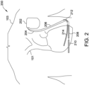
- FIG. 2 is a schematic diagram of another embodiment of an exemplary SICD system 200 that may be used to terminate VT in heart 101 of subject 103.
- SICD system 200 includes a case 202, a first conductive lead 204, and a second conductive lead 206 extending from case 202.
- First conductive lead 204 includes a first coil electrode 208 and a second coil electrode 210.
- second conductive lead 206 includes a third coil electrode 212 and a fourth coil electrode 214.
- First coil electrode 208 and second coil electrode 210 may be, for example, portions (e.g., halves) of a single linear defibrillation coil on first conductive lead 204.
- Third coil electrode 212 and fourth coil electrode 214 may similarly be portions (e.g., halves) of a single linear defibrillation coil on second conductive lead 206.
- first coil electrode 208 and second coil electrode 210 are anterior of heart 101, and second conductive lead 206 wraps around a side of the patient such that fourth coil electrode 214 is posterior of heart 101. Further, first coil electrode 208 and second coil electrode 210 are oriented generally parallel to fourth coil electrode 214.
- the case and coils of SICD system 200 may have any suitable position and orientation.
- case 202 may be located in a mid-axillary position, on the left side of the subject, similar to the position of case 302 (shown in FIG. 3 ).
- ATP may be achieved using first coil electrode 208, second coil electrode 210, or a combination of first coil electrode 208 and second coil electrode 210.
- evoked response may be detected using other combinations of the coils of SICD system 200.
- Table 3 lists several example pacing vectors and paced evoked response sensing electrode combinations. The numbers listed in Table 3 correspond to the part numbers of the components.
- the electrode combination that provides a smallest accelerometer signal (e.g., detected using an accelerometer in case 202) is used for ATP. This facilitates reducing unnecessary skeletal muscle stimulation. Further, in some embodiments, SICD system 200 may automatically analyze which electrode combination detects the largest evoked response and automatically use this combination for evoked response detection. Further, if no evoked response is detected, the amplitude of the ATP pulses may be increased.
- Table 4 lists several example electrode configurations for biphasic defibrillation pulse delivery with low DFT. Further, Table 4 lists corresponding electrode combinations for dual vector sensing. TABLE 4 Defibrillation Shocking Discrimination Sensing (Dual Vector) (214 and 210 and 208) to 202 208 to 210 214 to 202 (214 and 210 and 208) to 202 208 to 202 214 to 202 (214 and 210 and 208) to 202 210 to 202 214 to 202 (214 and 210 and 208) to 202 210 to 214 208 to 214 (214 and 210 and 208) to 202 210 to 202 208 to 214 (214 and 210 and 208) to 202 210 to 202 208 to 214 (214 and 210 and 208) to 202 208 to 202 210 to 214 (214 and 210 and 208) to 202 208 to 202 210 to 214 (214 and 210 and 208) to 202 208 to 202 210 to 214 to
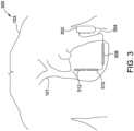
- FIG. 3 is a schematic diagram of another embodiment of an exemplary SICD system 300 that may be used to terminate VT in heart 101 of subject 103.
- SICD system 300 includes a case 302 and a first conductive lead 304 extending from case 302.
- First conductive lead 304 includes a first coil electrode 308, a second coil electrode 310, and a third coil electrode 312.
- First coil electrode 308, second coil electrode 310, and third coil electrode 312 may be, for example, portions (e.g., thirds) of a single linear defibrillation coil on first conductive lead 304.
- first coil electrode 308, second coil electrode 310, and third coil electrode 312 are anterior of heart 101. Further, first coil electrode 208 is oriented generally parallel to second coil electrode 310 and third coil electrode 312. Alternatively, the case and coils of SICD system 300 may have any suitable position and orientation. For example, in some embodiments, first coil electrode 308 may be segmented into two separate coils.
- ATP may be achieved using first coil electrode 308, second coil electrode 310, third coil electrode 312, or a combination of at least two of first coil electrode 308, second coil electrode 310, third coil electrode 312.
- evoked response may be detected using other combinations of the coils of SICD system 300.
- Table 5 lists several example pacing vectors and paced evoked response sensing electrode combinations. The numbers listed in Table 5 correspond to the part numbers of the components. TABLE 5 Pacing (Cathode to Anode) Paced Evoked Response Sensing Electrode Combinations 308 to 302 310 to 312 310 to 302 308 to 312 312 to 302 308 to 310
- the electrode combination that provides a smallest accelerometer signal (e.g., detected using an accelerometer in case 302) is used for ATP. This facilitates reducing unnecessary skeletal muscle stimulation. Further, in some embodiments, SICD system 300 may automatically analyze which electrode combination detects the largest evoked response and automatically use this combination for evoked response detection. Further, if no evoked response is detected, the amplitude of the ATP pulses may be increased.
- Table 6 lists several example electrode configurations for biphasic defibrillation pulse delivery with low DFT. Further, Table 6 lists corresponding electrode combinations for dual vector sensing. TABLE 6 Defibrillation Shocking Discrimination Sensing (Dual Vector) (308 and 310 and 312) to 302 310 to 312 308 to 302 (308 and 310 and 312) to 302 310 to 302 308 to 312 (308 and 310 and 312) to 302 308 to 302 310 to 312 (308 and 310 and 312) to 302 312 to 302 308 to 310 to 310 to 310 to 310 to 312 (308 and 310 and 312) to 302 312 to 302 308 to 310
- FIG. 4 is a circuit diagram of one embodiment of signal processing circuitry 400 including a sense amplifier 402.
- Signal processing circuitry 400 may be included within a case, such as cases 102, 202, and 302 (shown in FIGS. 1-3 ).
- sense amplifier 402 includes a first input 404 connected to a sensing electrode 405 and a second input 406 connected to a reference electrode 407. Further, a first input switch 410 is connected between first input 404 and sensing electrode 405, and a second input switch 414 is connected between second input 406 and reference electrode 407. In this embodiment, sensing electrode 405 and reference electrode 407 are different from a pacing electrode to prevent a pacing polarization artifact from obscuring the sensed evoked response.
- An output 420 of sense amplifier 402 is coupled to an analog to digital converter 422 via a resistor 424, an output switch 426, and a capacitor 428.
- first input switch 410, second input switch 414, and output switch 426 are opened (e.g., using the controller).
- Capacitor 428 acts as a sample and hold element, retaining the measured EKG level just prior to pacing.
- first input switch 410, second input switch 414, and output switch 426 are closed (e.g., using the controller), and sensing resumes.
- the digitized output signal is analyzed for an evoked response by determining if the derivative of the signal exceeds a negative or positive threshold (e.g., ⁇ 0.01 mV/ms) in a predetermined time period (e.g., 175 ms after the pacing pulse).
- a negative or positive threshold e.g., ⁇ 0.01 mV/ms
- a predetermined time period e.g., 175 ms after the pacing pulse.
- FIG. 5 is a trace of an example EKG 500 captured using signal processing circuitry 400 (shown in FIG. 4 ).
- EKG 500 includes paced QRS complexes 521 and 522.
- Pacing pulses 524 and 526 mark the onset of blanking, resulting in flat segments 528 and 529 following pacing pulses 524 and 526.
- Sudden sharp downward transitions 530 and 531 mark the end of the blanking, and occur during a mid-region of paced QRS complexes 521 and 522.
- the derivative of subsequent rapid upward deflections 535 and 537 can be processed to verify capture.
- EKG 500 further includes native QRS complexes 540 and 542 that were detected and thus inhibited pacing. Further, EKG 500 includes a pacing pulse 544 that is not followed by an evoked response. Thus, EKG 500 subsequently includes a native QRS 547 that emerges as a result of the loss of capture of pacing pulse 544.
- FIG. 6 is a flowchart of an algorithm 600 for providing ATP therapy to extinguish VT with a minimal number of pacing pulses.
- Algorithm 600 may be implemented, for example, using SICD systems 100, 200, and 300. Specifically, algorithm may be performed by the controller (e.g., a microprocessor) included in cases 102, 202, and 302. Algorithm 600 starts at block 602. Initially, in this embodiment, a percentage, Z, of a cycle length, CL, is set at 82%. The cycle length is defined as the time interval between subsequent R waves. Alternatively, Z may be set to any suitable value.
- At block 604 is determined whether at least 3 of 4 VT events satisfy certain criteria. Alternatively, other ratios may be used (e.g., 12 of 16 events). If the cycle length is greater than 320 ms (indicating a sinus rhythm) for at least 3 of 4 events, flow proceeds to block 606, and no action is taken. If the cycle length is less than 240 ms (indicating ventricular fibrillation (VF)) for at least 3 of 4 events, flow proceeds to block 608, and a defibrillating shock is delivered.
- 320 ms indicating a sinus rhythm
- VF ventricular fibrillation
- cycle length is greater than or equal to 240 ms and less than or equal to 320 ms (indicating VT) for at least 3 of 4 events.
- flow proceeds to block 610, and a single ATP pulse is delivered at Z (i.e., 82%) of the cycle length following the last event.
- block 612 it is determined whether capture is achieved based on the evoked response and/or extension of the cycle length. If capture is achieved, flow proceeds to block 614 and subsequently to block 616, where it is determined whether Z is less than 75%. If Z is not less than 75%, flow proceeds to block 618, at which point the amplitude of subsequent ATP pulses is increased (e.g., by 20%), and Z is reduced by 6%, before flow returns to block 602.
- a predetermined number of ATP pulses e.g., 4 to 5 pulses
- a predetermined number of ATP pulses e.g., 3 to 8 pulses
- flow proceeds to block 630 and subsequently to block 632, where it is determined whether Z is less than 100%. If Z is less than 100%, flow proceeds to block 634, at which point the amplitude of subsequent ATP pulses is increased (e.g., by 20%), and Z is increased by 6% (although keeping Z below 100%), before flow returns to block 604.
- a predetermined number of ATP pulses e.g., 4 to 5 pulses
- a predetermined number of ATP pulses e.g., 3 to 8 pulses
- discomfort from the applied ATP may be reduced using several techniques.
- the amplitude of the ATP pulses can be minimized by performing capture verification using the evoked response.
- the paced evoked response may be analyzed to perform capture verification and to determine the capture threshold (which may be, e.g., approximately 30 to 80 mA).
- the coil electrodes may be coated with a non-polarizable coating to reduce polarization, so that immediate sensing after pacing is possible.
- the sense amplifier can be blanked during pacing, and a sample and hold circuit (e.g., a capacitor) can be used to hold the ECG voltage during pacing to facilitate detecting the evoked response. If the evoked response is not detected, the ATP pulse amplitude may be increased on subsequent pulses until capture is achieved and verified from the evoked response.
- a sample and hold circuit e.g., a capacitor
- monophasic cathodic pulses are delivered instead of biphasic pulses.
- Monophasic cathode pulses have lower thresholds, and may be less noxious to the subject.
- a learning mode is implemented that is capable of recognizing a pulse regiment that is effective in achieving VT termination, and using that pulse regiment in terminate subsequent future arrhythmias. For example, if the VT has a cycle length of 300 ms, and is terminated by a 50 mA pulse at 93% of the cycle length, then the next time arrhythmia occurs, a 50 mA pulse is applied at 93% of the cycle length. Similarly, if the VT has a cycle length of 270 ms, and is terminated by a 80 mA pulse at 88% of the cycle length, then the next time arrhythmia occurs, a 80 mA pulse is applied at 88% of the cycle length.
- a predetermined (and programmable) number of ATP pulses are applied to attempt VT termination before shocking is implemented.
- an algorithm may be used to provide cardioversion with a predetermined number of ATP attempts.
- an in-line pacing electrode coil may be positioned over a point of maximum impulse (e.g., a V3 lead location) or in a parasternal location.
- the anode that does not provide the pacing may be the case or a larger electrode than the pacing electrode.
- the entire shocking electrode may be used to perform ATP, allowing for multisite pacing that may improve ATP efficacy in many patients.
- the shocking electrode may be divided into multiple segments, as described above. In such cases, pacing may be achieved using either segment individually or both segments combined. Further, the electrode combination that provides the lowest pacing threshold may be automatically selected using a capture verification algorithm that measures the pacing threshold.
- the segmented pacing electrode acts as one shocking electrode.
- Optimizing the pacing electrode size i.e., length
- each segment may have a length from approximately 3 to 6 centimeters (cm).
- a short coil segment is utilized for a first one or more rounds of ATP, allowing for adjustment of cycle length and/or pacing output in each consecutive ATP round.
- two or more coil segments are electrically coupled for delivering a second one or more rounds of ATP.
- the first one or more rounds elicit less skeletal muscle and/or diaphragmatic contraction
- the second one or more rounds more aggressively attempt to capture ventricular myocardium to penetrate into the VT circuit, with less regard for skeletal muscle and/or diaphragmatic contraction.
- a time optimization of ATP pulse delivery is controlled to coincide with spatial optimization.
- Spatial optimization may be controlled largely by selection of one or more stimulating electrodes. Specifically, the smaller the electrode and the closer to the myocardium, the more the electrode behaves like a point stimulator. In contrast, the larger the electrode and the further from the myocardium, the more the electrode behaves like a field stimulator. Field stimulation, at a tissue level, may result in multiple coordinated yet spatially distributed stimulation capture locations.
- first ATP attempt uses a single short coil segment at a low-to-moderate stimulation amplitude. This would be expected to result in a virtual point stimulation.
- modulation of timing with regard to cycle length can be performed (e.g., as described in associated with FIG. 6 ).
- subsequent ATP use one or more coil segments with larger dimensions than the coil segment of the first ATP attempt. Because of the larger size, the excitation at the same total energy will achieve stimulation that is more like field stimulation, which is more spatially diverse. Thus, when switching to a larger electrode, the Z value may be increased. Similarly, when switching to a larger coil length to reduce energy delivered (e.g., to avoid excessive stimulation of skeletal muscle), the Z value may be decreased accordingly.
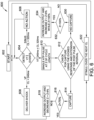
- FIG. 7 is a flowchart of an algorithm 700 for providing ATP therapy to extinguish VT that incorporates a learning mode.
- Algorithm 700 may be implemented, for example, using SICD systems 100, 200, and 300. Specifically, algorithm may be performed by the controller (e.g., a microprocessor) included in cases 102, 202, and 302. Further algorithm 700 may be implemented in combination with algorithm 600 (shown in FIG. 6 ).
- the controller e.g., a microprocessor
- ATP is applied using a particular vector and stimulation parameters
- An SICD implantable in a subject includes a case including a controller, and at least one conductive lead extending from the case.
- the at least one conductive lead includes a plurality of coil electrodes, wherein the SICD is configured, via the controller, to apply anti-tachycardia pacing (ATP) to the subject using the at least one conductive lead.
- the electrodes of the SICD may also be used to apply high voltage (HV) therapy.
Landscapes
- Health & Medical Sciences (AREA)
- Cardiology (AREA)
- Heart & Thoracic Surgery (AREA)
- Life Sciences & Earth Sciences (AREA)
- General Health & Medical Sciences (AREA)
- Engineering & Computer Science (AREA)
- Biomedical Technology (AREA)
- Nuclear Medicine, Radiotherapy & Molecular Imaging (AREA)
- Radiology & Medical Imaging (AREA)
- Animal Behavior & Ethology (AREA)
- Public Health (AREA)
- Veterinary Medicine (AREA)
- Biophysics (AREA)
- Physiology (AREA)
- Hematology (AREA)
- Electrotherapy Devices (AREA)
Description
- The present disclosure relates generally to pacing therapy, and more particularly to applying anti-tachycardia pacing using a subcutaneous implantable cardioverter-defibrillator.
- Heart failure (HF) is a debilitating, end-stage disease in which abnormal function of the heart leads to inadequate blood flow to fulfill the needs of the body's tissues. Typically, the heart loses propulsive power because the cardiac muscle loses capacity to stretch and contract. Often, the ventricles do not adequately fill with blood between heartbeats, and the valves regulating blood flow may develop leaks, allowing regurgitation or backflow of blood. The impairment of arterial circulation deprives vital organs of oxygen and nutrients. Fatigue, weakness, and inability to carry out daily tasks may result. Not all HF patients suffer debilitating symptoms immediately. Some may live actively for years. Yet, with few exceptions, the disease is relentlessly progressive. As HF progresses, it tends to become increasingly difficult to manage.
- Heart failure may result in patients experiencing ventricular arrhythmias, such as ventricular tachycardia (VT). VT may be treated by ablation and/or pacing.
- Subcutaneous implantable cardioverter-defibrillators (SICDs) are a type of implantable cardiac device (ICD) generally used in patients who do not require cardiac pacing. This pacing limitation, however, prevents a potentially large pool of patients from getting an SICD. Although it has been suggested that leadless pacemakers may be used in conjunction with SICDs to support the needs of patients who require pacing, leadless pacemakers require an additional implantation procedure and may be relatively expensive.
- Accordingly, it would be desirable to provide an SICD capable of treating VT by applying pacing.
-
US 2015/0306410 discloses implantable medical electrical leads having electrodes arranged such that a defibrillation coil electrode and a pace/sense electrode are concurrently positioned substantially over the ventricle when implanted. The leads include an elongated lead body having a distal portion and a proximal end, a connector at the proximal end of the lead body, a defibrillation electrode located along the distal portion of the lead body. The defibrillation electrode includes a first electrode segment and a second electrode segment proximal to the first electrode segment by a distance. The leads may include at least one pace/sense electrode located between the first defibrillation electrode segment and the second defibrillation electrode segment. -
US 2018/0071531 discloses devices and methods for single therapy pulse (STP) therapy for tacharrythmia. The STP therapy can be delivered from a far-field position to allow a "global" capture approach to pacing. Due to the global capture in STP, a series of pulses, which is indicative of conventional anti-tachycardia pacing (ATP) delivered by transvenous systems, becomes unnecessary. One to four pulses at most are needed for STP, and after delivery of the one to four pulses, therapy delivery can be interrupted to determine whether the previously delivered therapy has been successful. - In one embodiment, the present disclosure is directed to a subcutaneous implantable cardioverter-defibrillator (SICD) implantable in a subject. The SICD includes a case including a controller, and at least one conductive lead extending from the case, the at least one conductive lead including a plurality of coil electrodes, wherein the SICD is configured, via the controller, to apply anti-tachycardia pacing (ATP) to the subject using the at least one conductive lead.
- In another embodiment, the present disclosure is directed to a method of assembling a subcutaneous implantable cardioverter-defibrillator (SICD). The method includes coupling at least one conductive lead to a case, the at least one conductive lead including a plurality of coil electrodes. The method further includes installing a controller in the case, the controller configured to cause the SICD to apply anti-tachycardia pacing (ATP) to the subject using the at least one conductive lead.
- The foregoing and other aspects, features, details, utilities and advantages of the present disclosure will be apparent from reading the following description and claims, and from reviewing the accompanying drawings.
-
-
FIG. 1 is a schematic diagram of one embodiment of an exemplary SICD system that may be used to terminate VT in a heart of a subject. -
FIG. 2 is a schematic diagram of one embodiment of an exemplary SICD system that may be used to terminate VT in a heart of a subject. -
FIG. 3 is a schematic diagram of one embodiment of an exemplary SICD system that may be used to terminate VT in a heart of a subject. -
FIG. 4 is a circuit diagram of one embodiment of signal processing circuitry including a sense amplifier. -
FIG. 5 is a trace of an example EKG captured using the signal processing circuitry shown inFIG. 4 . -
FIG. 6 is a flowchart of an algorithm for providing ATP therapy to extinguish VT with a minimal number of pacing pulses. -
FIG. 7 is a flowchart of an algorithm for providing ATP therapy to extinguish VT that incorporates a learning mode. - Corresponding reference characters indicate corresponding parts throughout the several views of the drawings.
- The systems and methods described herein facilitate treating ventricular tachycardia (VT) by applying anti-tachycardia pacing (ATP) using a subcutaneous implantable cardioverter-defibrillator (SICD). That is, as described herein, the electrodes of an SICD may be used to treat patients that experience occasional VT. In some embodiments, the electrodes of the SICD may also be used to apply high voltage (HV) therapy.
-
FIGS. 1-3 are schematic diagrams of different embodiments of an exemplary subcutaneous implantable cardioverter defibrillator (SICD) system that may be used to apply ATP to facilitate treating VT. The embodiments shown inFIGS. 1-3 have been demonstrated, using computer modeling, to have relatively low defibrillation thresholds (DFTs) (i.e., the minimum amount of energy needed to return the heart to normal rhythm from cardiac dysrhythmia). For example, the embodiments shown inFIGS. 1-3 may have DFTs from approximately 16 to 18 Joules (J). As described herein, the defibrillation electrodes in these SICD systems may be adapted to perform subcutaneous ATP. In some embodiments, linear defibrillation coils are divided into two portions (e.g., halves) to perform ATP from each partial coil or to perform combined ATP. The delivery of the ATP (and sensing of the subsequent evoked response, etc.) is controlled by a controller (e.g., a microprocessor) installed in the case of these SICD systems. - In the embodiments described herein, ATP may be performed using pulses having an amplitude corresponding to a relatively small supra-threshold margin (e.g., approximately 1.2 times the DFT) at relatively large pulse widths (e.g., from approximately 4 to 40 milliseconds (ms)). These pulses may be minimized to reduce skeletal muscle stimulation in the subject. For example, pulses in the 20 to 200 milliamp (mA) range may be driven into a 50 ohm (Ω) load using only approximately 2 to 10 volts (V).
- In some embodiments, larger pacing pulses may be used to capture more of the subject's heart, which may increase the probability of a single ATP pulse (or relatively few ATP pulses) terminating VT. This facilitates treating VT without using high voltage defibrillation pulses.
- In the following description, with respect to the embodiments shown in
FIGS. 1-3 , several possible vectors (i.e., electrode combinations) for subcutaneous ATP are recommended, along with non-pacing electrode combinations that may be used for detecting the evoked response. However, those of skill in the art will appreciate that the pacing and evoked response electrode combinations identified herein are merely examples, and that other vectors and combinations may be used within the spirit and scope of the disclosure. -
FIG. 1 is a schematic diagram of one embodiment of anexemplary SICD system 100 that may be used to terminate VT in aheart 101 of asubject 103.SICD system 100 includes acase 102, a firstconductive lead 104, and a secondconductive lead 106 extending fromcase 102. Firstconductive lead 104 includes afirst coil electrode 108 and asecond coil electrode 110. Further, secondconductive lead 106 includes athird coil electrode 112 and afourth coil electrode 114.First coil electrode 108 andsecond coil electrode 110 may be, for example, portions (e.g., halves) of a single linear defibrillation coil on firstconductive lead 104.Third coil electrode 112 andfourth coil electrode 114 may similarly be portions (e.g., halves) of a single linear defibrillation coil on secondconductive lead 106. - In this embodiment,
first coil electrode 108 andsecond coil electrode 110 are anterior ofheart 101, and secondconductive lead 106 wraps around a side of the patient such thatfourth coil electrode 114 is posterior ofheart 101. Further,first coil electrode 108 andsecond coil electrode 110 are oriented generally orthogonally tofourth coil electrode 114. Alternatively, the case and coils ofSICD system 100 may have any suitable position and orientation. For example, in some embodiments,first coil electrode 108 is positioned closer tocase 102, andsecond coil electrode 110 is positioned approximately where first coil electrode is shown inFIG. 1 . In yet another embodiment,first coil electrode 108,second coil electrode 110,third coil electrode 112, andfourth coil electrode 114 are all included on a single lead that beings atcase 102, runs along the sternum, turns when proximate the xiphoid process, and wraps around to the side and back to place the coil electrodes in positions similar to those shown inFIG. 1 . - In this embodiment, ATP may be achieved using
first coil electrode 108,second coil electrode 110, or a combination offirst coil electrode 108 andsecond coil electrode 110. Further, an evoked response may be detected using other combinations of the coils ofSICD system 100. For example, the following Table 1 lists several example pacing vectors and paced evoked response sensing electrode combinations. The numbers listed in Table 1 correspond to the part numbers of the components.TABLE 1 Pacing (Cathode to Anode) Paced Evoked Response Sensing Electrode Combinations 110 to 102 108 to (112 and/or 114) 108 to 102 110 to (112 and/or 114) 110 to (112 and 114) 108 to 102 108 to (112 and 114) 110 to 102 108 to 110 102 to (112 and 114) 110 to 108 102 to (112 and 114) - In some embodiments, the electrode combination that provides a smallest accelerometer signal (e.g., detected using an accelerometer in case 102) is used for ATP (i.e., that combination is automatically selected by the controller). This facilitates reducing unnecessary skeletal muscle stimulation. Further, in some embodiments,
SICD system 100 may automatically analyze (using the controller) which electrode combination detects the largest evoked response and automatically use this combination for evoked response detection. Further, if no evoked response is detected, the amplitude of the ATP pulses may be increased. - The following Table 2 lists several example electrode configurations for biphasic defibrillation pulse delivery with low DFT. Further, Table 2 lists corresponding electrode combinations for dual vector sensing.
TABLE 2 Defibrillation Shocking Discrimination Sensing (Dual Vector) (102 and 108 and 110) to (112 and 114) 108 to 110 (112 and 114) to 102 (102 and 108 and 110) to (112 and 114) 108 to 102 (112 and 114) to 102 (102 and 108 and 110) to (112 and 114) 110 to 102 (112 and 114) to 102 (102 and 108 and 110) to (112 and 114) 110 to (112 and 114) (112 and 114) to 102 (102 and 108 and 110) to (112 and 114) 108 to (112 and 114) (112 and 114) to 102 - Because myopotentials may be generated by skeletal muscle contraction on one vector and not the other, a cross-correlation is performed between the two sensing vectors to increase the signal to noise ratio in such situations. See, for example,
U.S. Patent No. 7,970,473 , andU.S. Patent No. 7,447,540 . Further, in some embodiments, sensing vectors that provide a largest R-wave and/or a largest R-wave to T-wave ratio may be automatically selected to reduce the probability of under-sensing R-waves and over-sensing T-waves. -
FIG. 2 is a schematic diagram of another embodiment of anexemplary SICD system 200 that may be used to terminate VT inheart 101 ofsubject 103.SICD system 200 includes acase 202, a firstconductive lead 204, and a secondconductive lead 206 extending fromcase 202. Firstconductive lead 204 includes afirst coil electrode 208 and asecond coil electrode 210. Further, secondconductive lead 206 includes athird coil electrode 212 and afourth coil electrode 214.First coil electrode 208 andsecond coil electrode 210 may be, for example, portions (e.g., halves) of a single linear defibrillation coil on firstconductive lead 204.Third coil electrode 212 andfourth coil electrode 214 may similarly be portions (e.g., halves) of a single linear defibrillation coil on secondconductive lead 206. - In this embodiment,
first coil electrode 208 andsecond coil electrode 210 are anterior ofheart 101, and secondconductive lead 206 wraps around a side of the patient such thatfourth coil electrode 214 is posterior ofheart 101. Further,first coil electrode 208 andsecond coil electrode 210 are oriented generally parallel tofourth coil electrode 214. Alternatively, the case and coils ofSICD system 200 may have any suitable position and orientation. For example, in some embodiments,case 202 may be located in a mid-axillary position, on the left side of the subject, similar to the position of case 302 (shown inFIG. 3 ). - In this embodiment, ATP may be achieved using
first coil electrode 208,second coil electrode 210, or a combination offirst coil electrode 208 andsecond coil electrode 210. Further, evoked response may be detected using other combinations of the coils ofSICD system 200. For example, the following Table 3 lists several example pacing vectors and paced evoked response sensing electrode combinations. The numbers listed in Table 3 correspond to the part numbers of the components.TABLE 3 Pacing (Cathode to Anode) Paced Evoked Response Sensing Electrode Combinations 210 to 202 208 to (212 and/or 214) 208 to 202 210 to (212 and/or 214) 210 to (212 and 214) 208 to 202 208 to (212 and 214) 210 to 202 208 to 214 202 to 212 210 to 212 202 to 214 - As with
SICD system 100, in some embodiments, the electrode combination that provides a smallest accelerometer signal (e.g., detected using an accelerometer in case 202) is used for ATP. This facilitates reducing unnecessary skeletal muscle stimulation. Further, in some embodiments,SICD system 200 may automatically analyze which electrode combination detects the largest evoked response and automatically use this combination for evoked response detection. Further, if no evoked response is detected, the amplitude of the ATP pulses may be increased. - The following Table 4 lists several example electrode configurations for biphasic defibrillation pulse delivery with low DFT. Further, Table 4 lists corresponding electrode combinations for dual vector sensing.
TABLE 4 Defibrillation Shocking Discrimination Sensing (Dual Vector) (214 and 210 and 208) to 202 208 to 210 214 to 202 (214 and 210 and 208) to 202 208 to 202 214 to 202 (214 and 210 and 208) to 202 210 to 202 214 to 202 (214 and 210 and 208) to 202 210 to 214 208 to 214 (214 and 210 and 208) to 202 210 to 202 208 to 214 (214 and 210 and 208) to 202 208 to 202 210 to 214 -
FIG. 3 is a schematic diagram of another embodiment of anexemplary SICD system 300 that may be used to terminate VT inheart 101 ofsubject 103.SICD system 300 includes acase 302 and a firstconductive lead 304 extending fromcase 302. Firstconductive lead 304 includes afirst coil electrode 308, asecond coil electrode 310, and athird coil electrode 312.First coil electrode 308,second coil electrode 310, andthird coil electrode 312 may be, for example, portions (e.g., thirds) of a single linear defibrillation coil on firstconductive lead 304. - In this embodiment,
first coil electrode 308,second coil electrode 310, andthird coil electrode 312 are anterior ofheart 101. Further,first coil electrode 208 is oriented generally parallel tosecond coil electrode 310 andthird coil electrode 312. Alternatively, the case and coils ofSICD system 300 may have any suitable position and orientation. For example, in some embodiments,first coil electrode 308 may be segmented into two separate coils. - In this embodiment, ATP may be achieved using
first coil electrode 308,second coil electrode 310,third coil electrode 312, or a combination of at least two offirst coil electrode 308,second coil electrode 310,third coil electrode 312. Further, evoked response may be detected using other combinations of the coils ofSICD system 300. For example, the following Table 5 lists several example pacing vectors and paced evoked response sensing electrode combinations. The numbers listed in Table 5 correspond to the part numbers of the components.TABLE 5 Pacing (Cathode to Anode) Paced Evoked Response Sensing Electrode Combinations 308 to 302 310 to 312 310 to 302 308 to 312 312 to 302 308 to 310 - As with
SICD system 100, in some embodiments, the electrode combination that provides a smallest accelerometer signal (e.g., detected using an accelerometer in case 302) is used for ATP. This facilitates reducing unnecessary skeletal muscle stimulation. Further, in some embodiments,SICD system 300 may automatically analyze which electrode combination detects the largest evoked response and automatically use this combination for evoked response detection. Further, if no evoked response is detected, the amplitude of the ATP pulses may be increased. - The following Table 6 lists several example electrode configurations for biphasic defibrillation pulse delivery with low DFT. Further, Table 6 lists corresponding electrode combinations for dual vector sensing.
TABLE 6 Defibrillation Shocking Discrimination Sensing (Dual Vector) (308 and 310 and 312) to 302 310 to 312 308 to 302 (308 and 310 and 312) to 302 310 to 302 308 to 312 (308 and 310 and 312) to 302 308 to 302 310 to 312 (308 and 310 and 312) to 302 312 to 302 308 to 310 - When applying ATP using a SICD system (such as
SICD systems FIG. 4 is a circuit diagram of one embodiment ofsignal processing circuitry 400 including asense amplifier 402.Signal processing circuitry 400 may be included within a case, such ascases FIGS. 1-3 ). - As shown in
FIG. 4 ,sense amplifier 402 includes afirst input 404 connected to asensing electrode 405 and asecond input 406 connected to areference electrode 407. Further, afirst input switch 410 is connected betweenfirst input 404 andsensing electrode 405, and asecond input switch 414 is connected betweensecond input 406 andreference electrode 407. In this embodiment, sensingelectrode 405 andreference electrode 407 are different from a pacing electrode to prevent a pacing polarization artifact from obscuring the sensed evoked response. Anoutput 420 ofsense amplifier 402 is coupled to an analog todigital converter 422 via aresistor 424, anoutput switch 426, and acapacitor 428. - Just prior to delivering an ATP pulse (e.g., 1 ms before delivering an ATP pulse),
first input switch 410,second input switch 414, andoutput switch 426 are opened (e.g., using the controller).Capacitor 428 acts as a sample and hold element, retaining the measured EKG level just prior to pacing. After the pacing pulse is delivered (e.g., approximately 5 to 20 ms later),first input switch 410,second input switch 414, andoutput switch 426 are closed (e.g., using the controller), and sensing resumes. In this embodiment, the digitized output signal is analyzed for an evoked response by determining if the derivative of the signal exceeds a negative or positive threshold (e.g., ± 0.01 mV/ms) in a predetermined time period (e.g., 175 ms after the pacing pulse). -
FIG. 5 is a trace of anexample EKG 500 captured using signal processing circuitry 400 (shown inFIG. 4 ).EKG 500 includes pacedQRS complexes pulses flat segments pacing pulses downward transitions paced QRS complexes upward deflections - As shown in
FIG. 5 ,EKG 500 further includesnative QRS complexes EKG 500 includes a pacingpulse 544 that is not followed by an evoked response. Thus,EKG 500 subsequently includes anative QRS 547 that emerges as a result of the loss of capture of pacingpulse 544. -
FIG. 6 is a flowchart of analgorithm 600 for providing ATP therapy to extinguish VT with a minimal number of pacing pulses.Algorithm 600 may be implemented, for example, usingSICD systems cases Algorithm 600 starts atblock 602. Initially, in this embodiment, a percentage, Z, of a cycle length, CL, is set at 82%. The cycle length is defined as the time interval between subsequent R waves. Alternatively, Z may be set to any suitable value. - At
block 604, is determined whether at least 3 of 4 VT events satisfy certain criteria. Alternatively, other ratios may be used (e.g., 12 of 16 events). If the cycle length is greater than 320 ms (indicating a sinus rhythm) for at least 3 of 4 events, flow proceeds to block 606, and no action is taken. If the cycle length is less than 240 ms (indicating ventricular fibrillation (VF)) for at least 3 of 4 events, flow proceeds to block 608, and a defibrillating shock is delivered. If, however, the cycle length is greater than or equal to 240 ms and less than or equal to 320 ms (indicating VT) for at least 3 of 4 events, flow proceeds to block 610, and a single ATP pulse is delivered at Z (i.e., 82%) of the cycle length following the last event. - Subsequently, at
block 612, it is determined whether capture is achieved based on the evoked response and/or extension of the cycle length. If capture is achieved, flow proceeds to block 614 and subsequently to block 616, where it is determined whether Z is less than 75%. If Z is not less than 75%, flow proceeds to block 618, at which point the amplitude of subsequent ATP pulses is increased (e.g., by 20%), and Z is reduced by 6%, before flow returns to block 602. If Z is less than 75%, flow proceeds to block 622, and i) a predetermined number of ATP pulses (e.g., 4 to 5 pulses) are applied over the next cycle length at equally spaced intervals or, alternatively, ii) a predetermined number of ATP pulses (e.g., 3 to 8 pulses) are delivered at 88% of the cycle length. - At
block 612, if capture is not achieved, flow proceeds to block 630 and subsequently to block 632, where it is determined whether Z is less than 100%. If Z is less than 100%, flow proceeds to block 634, at which point the amplitude of subsequent ATP pulses is increased (e.g., by 20%), and Z is increased by 6% (although keeping Z below 100%), before flow returns to block 604. If Z is not less than 100%, flow proceeds to block 622, and i) a predetermined number of ATP pulses (e.g., 4 to 5 pulses) are applied over the next cycle length at equally spaced intervals or, alternatively, ii) a predetermined number of ATP pulses (e.g., 3 to 8 pulses) are delivered at 88% of the cycle length in an attempt to achieve capture. - In the systems and methods described herein, discomfort from the applied ATP may be reduced using several techniques.
- For example, in some embodiments, the amplitude of the ATP pulses can be minimized by performing capture verification using the evoked response. For example, the paced evoked response may be analyzed to perform capture verification and to determine the capture threshold (which may be, e.g., approximately 30 to 80 mA). Further, the coil electrodes may be coated with a non-polarizable coating to reduce polarization, so that immediate sensing after pacing is possible.
- Further, as described above, the sense amplifier can be blanked during pacing, and a sample and hold circuit (e.g., a capacitor) can be used to hold the ECG voltage during pacing to facilitate detecting the evoked response. If the evoked response is not detected, the ATP pulse amplitude may be increased on subsequent pulses until capture is achieved and verified from the evoked response.
- Further, in some embodiments, monophasic cathodic pulses are delivered instead of biphasic pulses. Monophasic cathode pulses have lower thresholds, and may be less noxious to the subject.
- In addition, in some embodiments, a learning mode is implemented that is capable of recognizing a pulse regiment that is effective in achieving VT termination, and using that pulse regiment in terminate subsequent future arrhythmias. For example, if the VT has a cycle length of 300 ms, and is terminated by a 50 mA pulse at 93% of the cycle length, then the next time arrhythmia occurs, a 50 mA pulse is applied at 93% of the cycle length. Similarly, if the VT has a cycle length of 270 ms, and is terminated by a 80 mA pulse at 88% of the cycle length, then the next time arrhythmia occurs, a 80 mA pulse is applied at 88% of the cycle length.
- In some embodiments, a predetermined (and programmable) number of ATP pulses are applied to attempt VT termination before shocking is implemented. Alternatively, an algorithm may be used to provide cardioversion with a predetermined number of ATP attempts.
- Further, in some embodiments, an in-line pacing electrode coil may be positioned over a point of maximum impulse (e.g., a V3 lead location) or in a parasternal location. The anode that does not provide the pacing may be the case or a larger electrode than the pacing electrode. In some embodiments, the entire shocking electrode may be used to perform ATP, allowing for multisite pacing that may improve ATP efficacy in many patients. Alternatively, the shocking electrode may be divided into multiple segments, as described above. In such cases, pacing may be achieved using either segment individually or both segments combined. Further, the electrode combination that provides the lowest pacing threshold may be automatically selected using a capture verification algorithm that measures the pacing threshold. For defibrillation, the segmented pacing electrode acts as one shocking electrode. Optimizing the pacing electrode size (i.e., length) may facilitate minimizing skeletal muscle stimulation while achieving adequate length for capture. For example, each segment may have a length from approximately 3 to 6 centimeters (cm).
- In addition, in some embodiments, a short coil segment is utilized for a first one or more rounds of ATP, allowing for adjustment of cycle length and/or pacing output in each consecutive ATP round. In case of failure in the first one or more rounds to terminate the VT, two or more coil segments are electrically coupled for delivering a second one or more rounds of ATP. In this scheme, the first one or more rounds elicit less skeletal muscle and/or diaphragmatic contraction, while the second one or more rounds more aggressively attempt to capture ventricular myocardium to penetrate into the VT circuit, with less regard for skeletal muscle and/or diaphragmatic contraction.
- In some embodiments, a time optimization of ATP pulse delivery is controlled to coincide with spatial optimization. Spatial optimization may be controlled largely by selection of one or more stimulating electrodes. Specifically, the smaller the electrode and the closer to the myocardium, the more the electrode behaves like a point stimulator. In contrast, the larger the electrode and the further from the myocardium, the more the electrode behaves like a field stimulator. Field stimulation, at a tissue level, may result in multiple coordinated yet spatially distributed stimulation capture locations.
- For example, suppose a first ATP attempt uses a single short coil segment at a low-to-moderate stimulation amplitude. This would be expected to result in a virtual point stimulation. If the first ATP attempt fails to terminate the VT, modulation of timing with regard to cycle length can be performed (e.g., as described in associated with
FIG. 6 ). In some embodiments, subsequent ATP use one or more coil segments with larger dimensions than the coil segment of the first ATP attempt. Because of the larger size, the excitation at the same total energy will achieve stimulation that is more like field stimulation, which is more spatially diverse. Thus, when switching to a larger electrode, the Z value may be increased. Similarly, when switching to a larger coil length to reduce energy delivered (e.g., to avoid excessive stimulation of skeletal muscle), the Z value may be decreased accordingly. - For example,
FIG. 7 is a flowchart of analgorithm 700 for providing ATP therapy to extinguish VT that incorporates a learning mode.Algorithm 700 may be implemented, for example, usingSICD systems cases Further algorithm 700 may be implemented in combination with algorithm 600 (shown inFIG. 6 ). - At
block 702, after ATP is applied using a particular vector and stimulation parameters, it is determined whether the ATP was successful in terminating VT. If the ATP was successful, flow proceeds to block 704, and the vector and stimulation parameters that were used in the ATP are recorded (i.e., stored) with an indication that the vector and stimulation parameters successfully terminated VT. Then, for future episodes, the recorded vector and stimulation parameters that previously resulted in terminating VT can be retrieved, and ATP is again applied using that same vector and stimulation parameters. - If, however, at
block 702, the ATP was not successful, flow proceeds to block 706, and the vector and stimulation parameters are recorded with an indication that they were unsuccessful. Then, atblock 708, at least one of the vector and the stimulation parameters are modified and ATP is applied again. Flow then returns to block 702 to determine whether this ATP was successful. - Accordingly, the systems and methods described herein facilitate applying anti-tachycardia pacing ATP to treat VT using subcutaneous implantable cardioverter-defibrillators SICDs. An SICD implantable in a subject includes a case including a controller, and at least one conductive lead extending from the case. The at least one conductive lead includes a plurality of coil electrodes, wherein the SICD is configured, via the controller, to apply anti-tachycardia pacing (ATP) to the subject using the at least one conductive lead. Further, those of skill in the art will appreciate that, in some embodiments, the electrodes of the SICD (and the electrode configurations described herein) may also be used to apply high voltage (HV) therapy.
- All directional references (e.g., upper, lower, upward, downward, left, right, leftward, rightward, top, bottom, above, below, vertical, horizontal, clockwise, and counterclockwise) are only used for identification purposes to aid the reader's understanding of the present disclosure, and do not create limitations, particularly as to the position, orientation, or use of the disclosure. Joinder references (e.g., attached, coupled, connected, and the like) are to be construed broadly and may include intermediate members between a connection of elements and relative movement between elements. As such, joinder references do not necessarily infer that two elements are directly connected and in fixed relation to each other. It is intended that all matter contained in the above description or shown in the accompanying drawings shall be interpreted as illustrative only and not limiting.
- When introducing elements of the present disclosure or the preferred embodiment(s) thereof, the articles "a", "an", "the", and "said" are intended to mean that there are one or more of the elements. The terms "comprising", "including", and "having" are intended to be inclusive and mean that there may be additional elements other than the listed elements.
Claims (15)
- A subcutaneous implantable cardioverter-defibrillator (SICD) (100; 200; 300) implantable in a subject (103) comprising:a case (102; 202; 302) comprising a controller; andat least one conductive lead (104, 106; 204, 206; 304) extending from the case (102; 202; 302), the at least one conductive lead (104, 106; 204, 206; 304) comprising a plurality of coil electrodes (108, 110, 112, 114; 208, 210, 212, 214; 308, 310, 312), wherein the SICD (100; 200; 300) is configured, via the controller, to apply anti-tachycardia pacing (ATP) to the subject (103) using the at least one conductive lead (104, 106; 204, 206; 304), characterized in that the controller is configured to select an electrode combination for applying the ATP based on at least one of i) an accelerometer signal and ii) a previously detected evoked response.
- The SICD of claim 1, wherein the SICD (100; 200; 300) is configured to apply anti-tachycardia pacing (ATP) by delivering pacing pulses having an amplitude from approximately 20 to 200 milliamps and a pulse width from approximately 4 to 40 milliseconds.
- The SICD of claim 1 or 2, wherein the at least one conductive lead (104, 106; 204, 206) comprises a first conductive lead (104; 204) and a second conductive lead (106; 206), the first conductive lead (104; 204) comprising a first coil electrode (108; 208) and a second coil electrode (110; 210), and the second conductive lead (106; 206) comprising a third coil electrode (112; 212) and a fourth coil electrode (114; 214).
- The SICD of claim 3, wherein to apply ATP, the SICD (100; 200) is configured to deliver pacing pulses from one of the first coil electrode (108; 208) and a second coil electrode (110; 210) to the case (102; 202).
- The SICD of claim 3 or 4, wherein the first coil electrode (108; 208) and the second coil electrode (110; 210) are portions of a single linear defibrillation coil.
- The SICD of any one of the claims 3 to 5, wherein the SICD (100; 200) is configured to be implanted such that the first and second coil electrodes (108, 110; 208, 210) are anterior of the subject's heart (101), and the fourth coil electrode (114; 214) is posterior of the subject's heart (101).
- The SICD of any of the claims 1 to 6, wherein the SICD (100; 200; 300) comprises an accelerometer in the case (102, 202, 302) and the controller is configured to select an electrode combination for applying the ATP that provides a smallest accelerometer signal detected using the accelerometer.
- The SICD of any one of the claims 1 to 7, wherein the at least one conductive lead (304) comprises a single conductive lead (304) comprising a first coil electrode (308), a second coil electrode (310), and a third coil electrode (312).
- The SICD of any one of the claims 1 to 8, wherein the case (102; 202; 302) further comprises signal processing circuitry (400) comprising a sense amplifier (402) and a plurality of switches (410, 414), and wherein the controller is configured to open the plurality of switches (410, 414) prior to delivery of a pacing pulse to prevent sensing of pacing pulse artifacts.
- The SICD of any one of the claims 1 to 9, wherein the controller is configured to cause ATP pulses to be delivered at a predetermined percentage of a cycle length, and wherein the controller is configured to adjust at least one of an output intensity and the predetermined percentage for subsequent pulses based at least in part on whether capture is achieved.
- A method of assembling a subcutaneous implantable cardioverter-defibrillator (SICD) (100; 200; 300), the method comprising:coupling at least one conductive lead (104, 106; 204, 206; 304) to a case (102; 202; 302), the at least one conductive lead (104, 106; 204, 206; 304) including a plurality of coil electrodes (108, 110, 112, 114; 208, 210, 212, 214; 308, 310, 312); andinstalling a controller in the case (102; 202; 302), the controller configured tocause the SICD (100; 200; 300) to apply anti-tachycardia pacing (ATP) to the subject using the at least one conductive lead (104, 106; 204, 206; 304), characterized in that to cause the SICD (100; 200; 300) to apply ATP, the controller is configured to select an electrode combination for applying the ATP based on at least one of i) an accelerometer signal and ii) a previously detected evoked response.
- The method of claim 11, wherein coupling at least one conductive lead (104, 106; 204, 206) to a case (102; 202) comprises coupling a first conductive lead (104; 204) and a second conductive lead (106; 206) to the case (102; 202), the first conductive lead (104; 204) including a first coil electrode (108; 208) and a second coil electrode (110; 210), and the second conductive lead (106; 206) including a third coil electrode (112; 212) and a fourth coil electrode (114; 214).
- The method of claim 12, wherein the first coil electrode (108; 208) and the second coil electrode (110; 210) are portions of a single linear defibrillation coil.
- The method of any one of the claims 11 to 13, wherein coupling at least one conductive lead (304) to a case (302) comprises coupling a single conductive lead (304) to the case (302), the single conductive lead (304) including a first coil electrode (308), a second coil electrode (310), and a third coil electrode (312).
- The method of any one of the claims 11 to 14, further comprising installing signal processing circuitry (400) in the case (102; 202; 302), the signal processing circuitry (400) including a sense amplifier (402) and a plurality of switches (410, 414), wherein the controller is further configured to open the plurality of switches (410, 414) prior to delivery of a pacing pulse to prevent sensing of pacing pulse artifacts.
Applications Claiming Priority (2)
| Application Number | Priority Date | Filing Date | Title |
|---|---|---|---|
| US16/057,605 US11951319B2 (en) | 2018-08-07 | 2018-08-07 | Systems and methods for applying anti-tachycardia pacing using subcutaneous implantable cardioverter-defibrillators |
| PCT/US2019/045243 WO2020033367A1 (en) | 2018-08-07 | 2019-08-06 | Systems and methods for applying anti-tachycardia pacing using subcutaneous implantable cardioverter-defibrillators |
Publications (2)
| Publication Number | Publication Date |
|---|---|
| EP3833426A1 EP3833426A1 (en) | 2021-06-16 |
| EP3833426B1 true EP3833426B1 (en) | 2024-10-30 |
Family
ID=67660829
Family Applications (1)
| Application Number | Title | Priority Date | Filing Date |
|---|---|---|---|
| EP19755751.5A Active EP3833426B1 (en) | 2018-08-07 | 2019-08-06 | Systems for applying anti-tachycardia pacing using subcutaneous implantable cardioverter-defibrillators |
Country Status (4)
| Country | Link |
|---|---|
| US (2) | US11951319B2 (en) |
| EP (1) | EP3833426B1 (en) |
| CN (1) | CN112533665B (en) |
| WO (1) | WO2020033367A1 (en) |
Families Citing this family (1)
| Publication number | Priority date | Publication date | Assignee | Title |
|---|---|---|---|---|
| CN117241857A (en) * | 2021-04-06 | 2023-12-15 | 脉冲动力公司 | Devices and methods for antitachycardia pacing |
Citations (1)
| Publication number | Priority date | Publication date | Assignee | Title |
|---|---|---|---|---|
| US7596410B1 (en) * | 2006-04-28 | 2009-09-29 | Pacesetter, Inc. | Tiered antitachycardia pacing and pre-pulsing therapy |
Family Cites Families (26)
| Publication number | Priority date | Publication date | Assignee | Title |
|---|---|---|---|---|
| US6879856B2 (en) * | 2000-03-21 | 2005-04-12 | Medtronic, Inc. | Method and apparatus for detection and treatment of tachycardia and fibrillation |
| US7149575B2 (en) | 2000-09-18 | 2006-12-12 | Cameron Health, Inc. | Subcutaneous cardiac stimulator device having an anteriorly positioned electrode |
| US6647292B1 (en) * | 2000-09-18 | 2003-11-11 | Cameron Health | Unitary subcutaneous only implantable cardioverter-defibrillator and optional pacer |
| US7069080B2 (en) * | 2000-09-18 | 2006-06-27 | Cameron Health, Inc. | Active housing and subcutaneous electrode cardioversion/defibrillating system |
| US6892094B2 (en) * | 2002-04-30 | 2005-05-10 | Medtronic, Inc. | Combined anti-tachycardia pacing (ATP) and high voltage therapy for treating ventricular arrhythmias |
| US7130681B2 (en) | 2003-05-09 | 2006-10-31 | Medtronic, Inc. | Use of accelerometer signal to augment ventricular arrhythmia detection |
| US7447540B1 (en) | 2004-11-24 | 2008-11-04 | Pacesetter, Inc. | Systems and methods for detection of VT and VF from remote sensing electrodes |
| US7515960B2 (en) * | 2005-03-31 | 2009-04-07 | Medtronic, Inc. | Method and apparatus to terminate ventricular tachycardia via pacing |
| US8478399B2 (en) * | 2006-01-31 | 2013-07-02 | Paul J. Degroot | Method and apparatus for controlling arrhythmia detection and treatment based on patient posture |
| US8209013B2 (en) * | 2006-09-14 | 2012-06-26 | Cardiac Pacemakers, Inc. | Therapeutic electrical stimulation that avoids undesirable activation |
| US9037239B2 (en) * | 2007-08-07 | 2015-05-19 | Cardiac Pacemakers, Inc. | Method and apparatus to perform electrode combination selection |
| US8718764B2 (en) * | 2008-09-16 | 2014-05-06 | Cardiac Pacemakers, Inc. | Cardiac function management integrating cardiac contractility modulation |
| US9031647B2 (en) * | 2010-11-18 | 2015-05-12 | Cardiac Pacemakers, Inc. | Guidewire and signal analyzer for pacing site optimization |
| US9849291B2 (en) * | 2011-06-09 | 2017-12-26 | Cameron Health, Inc. | Antitachycardia pacing pulse from a subcutaneous defibrillator |
| US8868178B2 (en) * | 2012-12-11 | 2014-10-21 | Galvani, Ltd. | Arrhythmia electrotherapy device and method with provisions for mitigating patient discomfort |
| US8744572B1 (en) * | 2013-01-31 | 2014-06-03 | Medronic, Inc. | Systems and methods for leadless pacing and shock therapy |
| US9950155B2 (en) * | 2013-03-15 | 2018-04-24 | Medtronic, Inc. | Identify insulation breach using electrograms |
| US10556117B2 (en) | 2013-05-06 | 2020-02-11 | Medtronic, Inc. | Implantable cardioverter-defibrillator (ICD) system including substernal pacing lead |
| US10004907B2 (en) * | 2014-02-21 | 2018-06-26 | Pacesetter, Inc. | Automatic capture verification within leadless implantable medical devices |
| US20150306375A1 (en) | 2014-04-25 | 2015-10-29 | Medtronic, Inc. | Implantable extravascular electrical stimulation lead having improved sensing and pacing capability |
| EP3174459B1 (en) * | 2014-07-29 | 2019-09-04 | Cardioflow Technologies, LLC | Systems to optimize anti-tachycardial pacing (atp) |
| US9636512B2 (en) * | 2014-11-05 | 2017-05-02 | Medtronic, Inc. | Implantable cardioverter-defibrillator (ICD) system having multiple common polarity extravascular defibrillation electrodes |
| US10765858B2 (en) * | 2014-11-05 | 2020-09-08 | Medtronic, Inc. | Extravascular lead designs for optimized pacing and sensing having segmented, partially electrically insulated defibrillation coils |
| US11027132B2 (en) * | 2016-03-16 | 2021-06-08 | Medtronic, Inc. | Synchronization of anti-tachycardia pacing in an extra-cardiovascular implantable system |
| US10201710B2 (en) * | 2016-04-28 | 2019-02-12 | Medtronic, Inc. | Latency-based adaptation of anti-tachyarrhythmia pacing therapy |
| CN110446529B (en) * | 2017-03-20 | 2023-06-09 | 心脏起搏器股份公司 | Implantable medical device |
-
2018
- 2018-08-07 US US16/057,605 patent/US11951319B2/en active Active
-
2019
- 2019-08-06 WO PCT/US2019/045243 patent/WO2020033367A1/en not_active Ceased
- 2019-08-06 EP EP19755751.5A patent/EP3833426B1/en active Active
- 2019-08-06 CN CN201980051591.6A patent/CN112533665B/en active Active
-
2024
- 2024-03-01 US US18/593,724 patent/US20240198119A1/en active Pending
Patent Citations (1)
| Publication number | Priority date | Publication date | Assignee | Title |
|---|---|---|---|---|
| US7596410B1 (en) * | 2006-04-28 | 2009-09-29 | Pacesetter, Inc. | Tiered antitachycardia pacing and pre-pulsing therapy |
Also Published As
| Publication number | Publication date |
|---|---|
| EP3833426A1 (en) | 2021-06-16 |
| WO2020033367A1 (en) | 2020-02-13 |
| US20200046991A1 (en) | 2020-02-13 |
| US11951319B2 (en) | 2024-04-09 |
| CN112533665B (en) | 2024-05-14 |
| US20240198119A1 (en) | 2024-06-20 |
| CN112533665A (en) | 2021-03-19 |
Similar Documents
| Publication | Publication Date | Title |
|---|---|---|
| US5978705A (en) | Method and apparatus for treating cardiac arrhythmia using auxiliary pulse | |
| US8447398B2 (en) | Subcutaneous implantable cardioverter-defibrillator placement methods | |
| US8644926B2 (en) | Subcutaneous defibrillator implantation | |
| US6275730B1 (en) | Method and apparatus for treating cardiac arrythmia | |
| US4727877A (en) | Method and apparatus for low energy endocardial defibrillation | |
| US20220409884A1 (en) | Subcutaneous implantable defibrillator with epicardial lead for resynchronization therapy | |
| EP0661078A2 (en) | Cardiac defibrillation lead having defibrillation and atrial sensing electrodes | |
| CN114984455B (en) | Systems, devices, and methods for synchronizing antitachycardia pacing in extra-cardiac implantable systems. | |
| US10130818B2 (en) | Method and apparatus for detecetion of intrinsic depolarization following high energy cardiac electrical stimulation | |
| JP2005523786A (en) | Implantable automatic defibrillator with subcutaneous electrode | |
| US20240198119A1 (en) | Systems and methods for applying anti-tachycardia pacing using subcutaneous implantable cardioverter-defibrillators | |
| US11642540B2 (en) | Implantable medical systems and methods for intercostal lead implant | |
| US7596410B1 (en) | Tiered antitachycardia pacing and pre-pulsing therapy | |
| US7751887B1 (en) | Tiered antitachycardia pacing and pre-pulsing therapy | |
| US20050131475A1 (en) | Precordial-superior vena cava electrode arrangement for an implantable cardioverter defibrillator | |
| US20030074027A1 (en) | Method and apparatus for termination of cardiac tachyarrhythmias | |
| WO2001017610A1 (en) | Method and apparatus for treating cardiac arrhythmia |
Legal Events
| Date | Code | Title | Description |
|---|---|---|---|
| STAA | Information on the status of an ep patent application or granted ep patent |
Free format text: STATUS: UNKNOWN |
|
| STAA | Information on the status of an ep patent application or granted ep patent |
Free format text: STATUS: THE INTERNATIONAL PUBLICATION HAS BEEN MADE |
|
| PUAI | Public reference made under article 153(3) epc to a published international application that has entered the european phase |
Free format text: ORIGINAL CODE: 0009012 |
|
| STAA | Information on the status of an ep patent application or granted ep patent |
Free format text: STATUS: REQUEST FOR EXAMINATION WAS MADE |
|
| 17P | Request for examination filed |
Effective date: 20210113 |
|
| AK | Designated contracting states |
Kind code of ref document: A1 Designated state(s): AL AT BE BG CH CY CZ DE DK EE ES FI FR GB GR HR HU IE IS IT LI LT LU LV MC MK MT NL NO PL PT RO RS SE SI SK SM TR |
|
| DAV | Request for validation of the european patent (deleted) | ||
| DAX | Request for extension of the european patent (deleted) | ||
| P01 | Opt-out of the competence of the unified patent court (upc) registered |
Effective date: 20230616 |
|
| RAP3 | Party data changed (applicant data changed or rights of an application transferred) |
Owner name: PACESETTER, INC. |
|
| GRAJ | Information related to disapproval of communication of intention to grant by the applicant or resumption of examination proceedings by the epo deleted |
Free format text: ORIGINAL CODE: EPIDOSDIGR1 |
|
| STAA | Information on the status of an ep patent application or granted ep patent |
Free format text: STATUS: GRANT OF PATENT IS INTENDED |
|
| PUAG | Search results despatched under rule 164(2) epc together with communication from examining division |
Free format text: ORIGINAL CODE: 0009017 |
|
| GRAP | Despatch of communication of intention to grant a patent |
Free format text: ORIGINAL CODE: EPIDOSNIGR1 |
|
| RIC1 | Information provided on ipc code assigned before grant |
Ipc: A61N 1/37 20060101ALI20240718BHEP Ipc: A61N 1/365 20060101ALI20240718BHEP Ipc: A61N 1/362 20060101AFI20240718BHEP |
|
| B565 | Issuance of search results under rule 164(2) epc |
Effective date: 20240731 |
|
| INTG | Intention to grant announced |
Effective date: 20240731 |
|
| RIC1 | Information provided on ipc code assigned before grant |
Ipc: A61N 1/37 20060101ALI20240723BHEP Ipc: A61N 1/365 20060101ALI20240723BHEP Ipc: A61N 1/362 20060101AFI20240723BHEP |
|
| GRAS | Grant fee paid |
Free format text: ORIGINAL CODE: EPIDOSNIGR3 |
|
| GRAA | (expected) grant |
Free format text: ORIGINAL CODE: 0009210 |
|
| STAA | Information on the status of an ep patent application or granted ep patent |
Free format text: STATUS: THE PATENT HAS BEEN GRANTED |
|
| AK | Designated contracting states |
Kind code of ref document: B1 Designated state(s): AL AT BE BG CH CY CZ DE DK EE ES FI FR GB GR HR HU IE IS IT LI LT LU LV MC MK MT NL NO PL PT RO RS SE SI SK SM TR |
|
| REG | Reference to a national code |
Ref country code: GB Ref legal event code: FG4D |
|
| REG | Reference to a national code |
Ref country code: CH Ref legal event code: EP |
|
| REG | Reference to a national code |
Ref country code: IE Ref legal event code: FG4D |
|
| REG | Reference to a national code |
Ref country code: DE Ref legal event code: R096 Ref document number: 602019061143 Country of ref document: DE |
|
| REG | Reference to a national code |
Ref country code: LT Ref legal event code: MG9D |
|
| REG | Reference to a national code |
Ref country code: NL Ref legal event code: MP Effective date: 20241030 |
|
| PG25 | Lapsed in a contracting state [announced via postgrant information from national office to epo] |
Ref country code: IS Free format text: LAPSE BECAUSE OF FAILURE TO SUBMIT A TRANSLATION OF THE DESCRIPTION OR TO PAY THE FEE WITHIN THE PRESCRIBED TIME-LIMIT Effective date: 20250228 Ref country code: HR Free format text: LAPSE BECAUSE OF FAILURE TO SUBMIT A TRANSLATION OF THE DESCRIPTION OR TO PAY THE FEE WITHIN THE PRESCRIBED TIME-LIMIT Effective date: 20241030 Ref country code: PT Free format text: LAPSE BECAUSE OF FAILURE TO SUBMIT A TRANSLATION OF THE DESCRIPTION OR TO PAY THE FEE WITHIN THE PRESCRIBED TIME-LIMIT Effective date: 20250228 |
|
| PG25 | Lapsed in a contracting state [announced via postgrant information from national office to epo] |
Ref country code: FI Free format text: LAPSE BECAUSE OF FAILURE TO SUBMIT A TRANSLATION OF THE DESCRIPTION OR TO PAY THE FEE WITHIN THE PRESCRIBED TIME-LIMIT Effective date: 20241030 Ref country code: NL Free format text: LAPSE BECAUSE OF FAILURE TO SUBMIT A TRANSLATION OF THE DESCRIPTION OR TO PAY THE FEE WITHIN THE PRESCRIBED TIME-LIMIT Effective date: 20241030 |
|
| REG | Reference to a national code |
Ref country code: AT Ref legal event code: MK05 Ref document number: 1736343 Country of ref document: AT Kind code of ref document: T Effective date: 20241030 |
|
| PG25 | Lapsed in a contracting state [announced via postgrant information from national office to epo] |
Ref country code: BG Free format text: LAPSE BECAUSE OF FAILURE TO SUBMIT A TRANSLATION OF THE DESCRIPTION OR TO PAY THE FEE WITHIN THE PRESCRIBED TIME-LIMIT Effective date: 20241030 |
|
| PG25 | Lapsed in a contracting state [announced via postgrant information from national office to epo] |
Ref country code: ES Free format text: LAPSE BECAUSE OF FAILURE TO SUBMIT A TRANSLATION OF THE DESCRIPTION OR TO PAY THE FEE WITHIN THE PRESCRIBED TIME-LIMIT Effective date: 20241030 |
|
| PG25 | Lapsed in a contracting state [announced via postgrant information from national office to epo] |
Ref country code: NO Free format text: LAPSE BECAUSE OF FAILURE TO SUBMIT A TRANSLATION OF THE DESCRIPTION OR TO PAY THE FEE WITHIN THE PRESCRIBED TIME-LIMIT Effective date: 20250130 |
|
| PG25 | Lapsed in a contracting state [announced via postgrant information from national office to epo] |
Ref country code: AT Free format text: LAPSE BECAUSE OF FAILURE TO SUBMIT A TRANSLATION OF THE DESCRIPTION OR TO PAY THE FEE WITHIN THE PRESCRIBED TIME-LIMIT Effective date: 20241030 Ref country code: LV Free format text: LAPSE BECAUSE OF FAILURE TO SUBMIT A TRANSLATION OF THE DESCRIPTION OR TO PAY THE FEE WITHIN THE PRESCRIBED TIME-LIMIT Effective date: 20241030 Ref country code: GR Free format text: LAPSE BECAUSE OF FAILURE TO SUBMIT A TRANSLATION OF THE DESCRIPTION OR TO PAY THE FEE WITHIN THE PRESCRIBED TIME-LIMIT Effective date: 20250131 |
|
| PG25 | Lapsed in a contracting state [announced via postgrant information from national office to epo] |
Ref country code: PL Free format text: LAPSE BECAUSE OF FAILURE TO SUBMIT A TRANSLATION OF THE DESCRIPTION OR TO PAY THE FEE WITHIN THE PRESCRIBED TIME-LIMIT Effective date: 20241030 |
|
| PG25 | Lapsed in a contracting state [announced via postgrant information from national office to epo] |
Ref country code: RS Free format text: LAPSE BECAUSE OF FAILURE TO SUBMIT A TRANSLATION OF THE DESCRIPTION OR TO PAY THE FEE WITHIN THE PRESCRIBED TIME-LIMIT Effective date: 20250130 |
|
| PG25 | Lapsed in a contracting state [announced via postgrant information from national office to epo] |
Ref country code: SM Free format text: LAPSE BECAUSE OF FAILURE TO SUBMIT A TRANSLATION OF THE DESCRIPTION OR TO PAY THE FEE WITHIN THE PRESCRIBED TIME-LIMIT Effective date: 20241030 |
|
| PG25 | Lapsed in a contracting state [announced via postgrant information from national office to epo] |
Ref country code: DK Free format text: LAPSE BECAUSE OF FAILURE TO SUBMIT A TRANSLATION OF THE DESCRIPTION OR TO PAY THE FEE WITHIN THE PRESCRIBED TIME-LIMIT Effective date: 20241030 |
|
| PG25 | Lapsed in a contracting state [announced via postgrant information from national office to epo] |
Ref country code: EE Free format text: LAPSE BECAUSE OF FAILURE TO SUBMIT A TRANSLATION OF THE DESCRIPTION OR TO PAY THE FEE WITHIN THE PRESCRIBED TIME-LIMIT Effective date: 20241030 |
|
| PG25 | Lapsed in a contracting state [announced via postgrant information from national office to epo] |
Ref country code: RO Free format text: LAPSE BECAUSE OF FAILURE TO SUBMIT A TRANSLATION OF THE DESCRIPTION OR TO PAY THE FEE WITHIN THE PRESCRIBED TIME-LIMIT Effective date: 20241030 |
|
| PG25 | Lapsed in a contracting state [announced via postgrant information from national office to epo] |
Ref country code: SK Free format text: LAPSE BECAUSE OF FAILURE TO SUBMIT A TRANSLATION OF THE DESCRIPTION OR TO PAY THE FEE WITHIN THE PRESCRIBED TIME-LIMIT Effective date: 20241030 |
|
| PG25 | Lapsed in a contracting state [announced via postgrant information from national office to epo] |
Ref country code: CZ Free format text: LAPSE BECAUSE OF FAILURE TO SUBMIT A TRANSLATION OF THE DESCRIPTION OR TO PAY THE FEE WITHIN THE PRESCRIBED TIME-LIMIT Effective date: 20241030 |
|
| REG | Reference to a national code |
Ref country code: DE Ref legal event code: R097 Ref document number: 602019061143 Country of ref document: DE |
|
| PLBE | No opposition filed within time limit |
Free format text: ORIGINAL CODE: 0009261 |
|
| STAA | Information on the status of an ep patent application or granted ep patent |
Free format text: STATUS: NO OPPOSITION FILED WITHIN TIME LIMIT |
|
| PG25 | Lapsed in a contracting state [announced via postgrant information from national office to epo] |
Ref country code: SE Free format text: LAPSE BECAUSE OF FAILURE TO SUBMIT A TRANSLATION OF THE DESCRIPTION OR TO PAY THE FEE WITHIN THE PRESCRIBED TIME-LIMIT Effective date: 20241030 |
|
| 26N | No opposition filed |
Effective date: 20250731 |
|
| PGFP | Annual fee paid to national office [announced via postgrant information from national office to epo] |
Ref country code: DE Payment date: 20250709 Year of fee payment: 7 |
|
| PGFP | Annual fee paid to national office [announced via postgrant information from national office to epo] |
Ref country code: IT Payment date: 20250811 Year of fee payment: 7 |
|
| PGFP | Annual fee paid to national office [announced via postgrant information from national office to epo] |
Ref country code: FR Payment date: 20250709 Year of fee payment: 7 |
|
| PGFP | Annual fee paid to national office [announced via postgrant information from national office to epo] |
Ref country code: CH Payment date: 20250901 Year of fee payment: 7 |
|
| PGFP | Annual fee paid to national office [announced via postgrant information from national office to epo] |
Ref country code: IE Payment date: 20250709 Year of fee payment: 7 |
|
| PG25 | Lapsed in a contracting state [announced via postgrant information from national office to epo] |
Ref country code: MC Free format text: LAPSE BECAUSE OF FAILURE TO SUBMIT A TRANSLATION OF THE DESCRIPTION OR TO PAY THE FEE WITHIN THE PRESCRIBED TIME-LIMIT Effective date: 20241030 |
|
| PG25 | Lapsed in a contracting state [announced via postgrant information from national office to epo] |
Ref country code: LU Free format text: LAPSE BECAUSE OF NON-PAYMENT OF DUE FEES Effective date: 20250806 |
|
| GBPC | Gb: european patent ceased through non-payment of renewal fee |
Effective date: 20250806 |