EP3833227B1 - Easily insertable cup support - Google Patents
Easily insertable cup support Download PDFInfo
- Publication number
- EP3833227B1 EP3833227B1 EP19752486.1A EP19752486A EP3833227B1 EP 3833227 B1 EP3833227 B1 EP 3833227B1 EP 19752486 A EP19752486 A EP 19752486A EP 3833227 B1 EP3833227 B1 EP 3833227B1
- Authority
- EP
- European Patent Office
- Prior art keywords
- connection
- machine
- receiver
- beverage
- connecting part
- Prior art date
- Legal status (The legal status is an assumption and is not a legal conclusion. Google has not performed a legal analysis and makes no representation as to the accuracy of the status listed.)
- Active
Links
Images
Classifications
-
- A—HUMAN NECESSITIES
- A47—FURNITURE; DOMESTIC ARTICLES OR APPLIANCES; COFFEE MILLS; SPICE MILLS; SUCTION CLEANERS IN GENERAL
- A47J—KITCHEN EQUIPMENT; COFFEE MILLS; SPICE MILLS; APPARATUS FOR MAKING BEVERAGES
- A47J31/00—Apparatus for making beverages
- A47J31/44—Parts or details or accessories of beverage-making apparatus
- A47J31/4403—Constructional details
- A47J31/441—Warming devices or supports for beverage containers
- A47J31/4425—Supports for beverage containers when filled or while being filled
- A47J31/4428—Supports for beverage containers when filled or while being filled with a drip-tray underneath
-
- A—HUMAN NECESSITIES
- A47—FURNITURE; DOMESTIC ARTICLES OR APPLIANCES; COFFEE MILLS; SPICE MILLS; SUCTION CLEANERS IN GENERAL
- A47J—KITCHEN EQUIPMENT; COFFEE MILLS; SPICE MILLS; APPARATUS FOR MAKING BEVERAGES
- A47J31/00—Apparatus for making beverages
- A47J31/40—Beverage-making apparatus with dispensing means for adding a measured quantity of ingredients, e.g. coffee, water, sugar, cocoa, milk, tea
- A47J31/407—Beverage-making apparatus with dispensing means for adding a measured quantity of ingredients, e.g. coffee, water, sugar, cocoa, milk, tea with ingredient-containing cartridges; Cartridge-perforating means
-
- A—HUMAN NECESSITIES
- A47—FURNITURE; DOMESTIC ARTICLES OR APPLIANCES; COFFEE MILLS; SPICE MILLS; SUCTION CLEANERS IN GENERAL
- A47J—KITCHEN EQUIPMENT; COFFEE MILLS; SPICE MILLS; APPARATUS FOR MAKING BEVERAGES
- A47J31/00—Apparatus for making beverages
- A47J31/44—Parts or details or accessories of beverage-making apparatus
- A47J31/4403—Constructional details
-
- A—HUMAN NECESSITIES
- A47—FURNITURE; DOMESTIC ARTICLES OR APPLIANCES; COFFEE MILLS; SPICE MILLS; SUCTION CLEANERS IN GENERAL
- A47J—KITCHEN EQUIPMENT; COFFEE MILLS; SPICE MILLS; APPARATUS FOR MAKING BEVERAGES
- A47J31/00—Apparatus for making beverages
- A47J31/44—Parts or details or accessories of beverage-making apparatus
- A47J31/4482—Details allowing to adapt the beverage-making apparatus to the size of the brewing vessel or the beverage container, e.g. with adjustable support for the beverage container or adjustable hot water outlet
-
- A—HUMAN NECESSITIES
- A47—FURNITURE; DOMESTIC ARTICLES OR APPLIANCES; COFFEE MILLS; SPICE MILLS; SUCTION CLEANERS IN GENERAL
- A47J—KITCHEN EQUIPMENT; COFFEE MILLS; SPICE MILLS; APPARATUS FOR MAKING BEVERAGES
- A47J31/00—Apparatus for making beverages
- A47J31/44—Parts or details or accessories of beverage-making apparatus
- A47J31/46—Dispensing spouts, pumps, drain valves or like liquid transporting devices
Definitions
- the field of the invention pertains to beverage dispensing machines having a beverage outlet, a service unit and a movable cup support.
- the beverage preparation machine uses receptacles of an ingredient of the beverage to be prepared, in particular to machine is arranged to prepare the beverage by circulation of a liquid into the ingredient receptacle and centrifugation thereof, typically to brew the beverage in the ingredient receptacle and extract the beverage therefrom.
- a "beverage” is meant to include any human-consumable liquid substance, such as tea, coffee, hot or cold chocolate, milk, soup, baby food, etc...
- a "receptacle” is meant to include any container such as a packaging for containing a pre-portioned beverage ingredient, e.g. a flavouring ingredient, the packaging forming an enclosure, e.g. a capsule, of any material, in particular an airtight or pervious material, porous or non-porous material, e.g. plastic, aluminium, recyclable and/or biodegradable packagings, and of any shape and structure, including soft pods or rigid cartridges for containing the ingredient.
- Certain beverage preparation machines use capsules containing ingredients to be extracted or to be dissolved; for other machines, the ingredients are stored and dosed automatically in the machine or else are added at the time of preparation of the drink.
- filling means that include a pump for liquid, usually water, which pumps the liquid from a source of water that is cold or indeed heated through heating means, such as a heating resistor, a thermoblock or the like, a brewing unit in which an ingredient is brewed with water or a mixing unit in which ingredients are mixed together, and a beverage outlet for dispensing the prepared beverage.
- heating means such as a heating resistor, a thermoblock or the like
- a brewing unit in which an ingredient is brewed with water or a mixing unit in which ingredients are mixed together
- beverage outlet for dispensing the prepared beverage are disclosed in US 2,715,868 , 5,392,694 , 5,943,472 , 5,992,298 , 6,554,588 , WO 2006/032599 , WO 2009/024500 , WO 2009/150030 and WO 2010/006953 .
- the beverage outlet is located above a grid for supporting a cup or other recipient under the outlet and for the passage of possible drops from the beverage outlet or other spills into a collector tray located under the grid.
- Examples of such machines are disclosed in EP 0 549 887 , EP 1 440 639 , EP 1 731 065 , EP 1 867 260 , US 5,161,455 , US 5,353,692 , WO 2009/074557 , WO 2009/074559 , WO 2009/135869 , WO 2011/154492 , WO 2012/007313 , WO 2013/186339 , WO 2016/096705 , WO 2016/096706 , WO 2016/096707 , WO 2016/156364 , WO 2016/156367 and WO 2016/156368 .
- a machine for dispensing a beverage comprising a machine body and a recipient support disconnectably connectable to the machine body is known from EP3213662A1 .
- An object of the invention is to provide a solution encountered with prior art configurations or at least an alternative to the prior art configurations.
- a preferred object of the invention is to provide a beverage dispensing machine with an ergonomic cup support.
- Another preferred object of the invention is to provide a beverage dispensing machine with a cup support that can be assembled and disassembled from a machine's counterpart in a simple manner.
- a further preferred object of the invention is to provide a beverage dispensing machine with a cup support that can be easily manufactured.
- the invention thus relates to a machine for dispensing a beverage, such as a beverage prepared from a receptacle containing a beverage ingredient, as defined in claim 1.
- the beverage preparation typically includes the mixing of a plurality of beverage ingredients, e.g. water and milk powder, and/or the infusion of a beverage ingredient, such as an infusion of ground coffee or tea with water.
- a beverage ingredient such as an infusion of ground coffee or tea with water.
- One or more of such ingredients may be supplied in loose and/or agglomerate powder form and/or in liquid form, e.g. in a concentrate form.
- a carrier or dilution liquid, e.g. water may be mixed with such ingredient to form the beverage.
- a predetermined amount of beverage is formed and dispensed on user-request, which corresponds to a serving.
- the volume of such a serving may be in the range of 25 to 200 ml or up to 300 or 400 ml, e.g. the volume for filling a cup or mug, depending on the type of beverage.
- Formed and dispensed beverages may be selected from ristrettos, espressos, lungos, cappuccinos, café latte, americano coffees, teas, etc...
- a coffee machine may be configured for dispensing espressos, e.g. an adjustable volume of 20 to 60 ml per serving, and/or for dispensing lungos, e.g. a volume in the range of 70 to 150 ml per serving.
- the machine includes: a beverage outlet that is located above a dispensing area; a machine body or frame having a first connecting part and bearing the beverage outlet; and a recipient support having a second connecting part and a support member held, directly or indirectly, by the second connecting part.
- the machine includes an external housing having an external front face.
- the housing may have at least one of: one or more external lateral side faces; an external rear face; an external top face; and an external bottom face.
- the beverage outlet may be located on the external front face.
- Suitable advanced beverage outlet configurations are for instance disclosed in WO 2006/050769 , WO 2012/072758 , WO 2013/127907 , EP2014186738.2 , EP2014195048.5 , EP14195067.5 , EP2017208722.3 , EP2017208727.2 and EP2017208731.4 .
- drop management is optional.
- a simple machine outlet of the type disclosed in US8091469 or WO 2009/074550 can be used.
- the second connecting part is disconnectably connectable to the first connecting part so that the support member extends into the dispensing area to support a beverage user-recipient, e.g. a cup or a mug, under the beverage outlet.
- a beverage user-recipient e.g. a cup or a mug
- the first connecting part and the second connecting part have a connection member and a connection receiver arrangement, e.g. a plug and socket arrangement, for disconnectably connecting the parts such that: the first connecting part forms a connection member and the second connecting part forms a connection receiver; or the first connecting part forms a connection receiver and the second connecting part forms a connection member.
- a connection receiver arrangement e.g. a plug and socket arrangement
- the first connecting part may include one or more connection receivers, the second connecting part including a corresponding number of matching connection members.
- the second connecting part may include one or more connection receivers, the first connecting part including a corresponding number of matching connection members.
- the first connecting part may include a combination of connection member(s) and receiver(s), the second connecting part including a corresponding combination of matching connection receiver(s) and member(s).
- connection member are inserted in the connection receiver when the first and second connecting parts are connected, the connection member being removed from the connection receiver along a removal direction when the first and second connecting parts are disconnected.
- connection member projects into the connection receiver when the first and second connecting parts are connected.
- the removal direction has an upwardly directed vertical component when such machine is in position to dispense said beverage.
- the machine is placed with a machine bottom on an external generally horizontal support surface.
- the recipient support can be automatically secured to the machine body or frame by gravity (under its own weight) and even further secured by the effect of the weight of a beverage user-recipient on the recipient support.
- Such a configuration can be beneficial, particularly during beverage preparation, if the machine vibrates so as to prevent or inhibit undesired disconnection of the recipient support from the machine body or frame due to vibrations.
- the connecting parts may be magnetically constrained in the connected state.
- the connecting parts are fitted with a pair of magnetic field-generating elements, or with a magnetic field-generating element and a ferromagnetic element.
- the magnetic field-generating element can have an electromagnet element or a permanent magnet element, e.g. made of at least one of iron, nickel, cobalt, rare earth metals, e.g. lanthanide, and alloys and oxides containing such metals as well as polymers (e.g. plastics) carrying such elements and components.
- an electromagnet element or a permanent magnet element e.g. made of at least one of iron, nickel, cobalt, rare earth metals, e.g. lanthanide, and alloys and oxides containing such metals as well as polymers (e.g. plastics) carrying such elements and components.
- the ferromagnetic element may be made of at least one of Co, Fe, Fe 2 O 3 , FeOFe 2 O 3 , NiOFe 2 O 3 , CuOFe 2 O 3 , MgO Fe 2 O 3 , Nd 2 Fe 14 B, Mn, Bi, Ni, MnSb, MnOFe 2 O 3 , Y 3 Fe 5 O 12 , CrO 2 , MnAs, Gd, Dy, EuO, Cu 2 MnAl, Cu 2 MnIn, Cu 2 MnSn, Ni 2 MnAl, Ni 2 MnIn, Ni 2 MnSn, Ni 2 MnSb, Ni 2 MnGa, Co 2 MnAl, Co 2 MnSi, Co 2 MnGa, Co 2 MnGe, SmCo 5 , Sm 2 Co 17 , Pd 2 MnAl, Pd 2 MnIn, Pd 2 MnSn, Pd 2 MnSb, Co 2 FeSi, Fe 3 Si, Fe
- the upwardly directed vertical component of the removal direction can be opposite to a vertical component of a force exercised by the beverage user-recipient on the support member when placed thereon under the beverage outlet.
- connection member can be in the shape generally of a rod or a bar extending along the removal direction when the first and second connecting parts are connected.
- the connection receiver may have a corresponding shape such that the connection member can be slid in an out of the connection receiver.
- connection receiver and/or the connection member can have a connection approaching extremity, such as an insertion aperture of the connection receiver or a free end of the connection member, that allows for a mechanical positioning play between the connection member and the connection receiver when approaching each other at insertion.
- a connection approaching extremity such as an insertion aperture of the connection receiver or a free end of the connection member, that allows for a mechanical positioning play between the connection member and the connection receiver when approaching each other at insertion.
- the approaching extremity is tapered or flared, e.g. rounded or bevelled, to facilitate insertion (e.g. by allowing self-positioning) of the connection member into the connection receiver.
- the receiver connection approaching extremity may be flared and the member connection approaching extremity may be tapered.
- connection approaching extremity can be asymmetric to provide a mechanical positioning play only on an extremity play portion generally opposite to an extremity urging portion against which a main urging force is exercised by the first connecting part on the second connecting part when the second connecting part is connected to the first connecting part.
- the first connecting part may exercise a first main urging force at the connection approaching extremity and a second main urging force at an extremity opposite thereto.
- connection member and the connection receiver are secured in a cantilever manner by gravity force of the support member when such machine is in position to dispense the beverage: a or the above free end of the connection member in the connection receiver is urged down by the connection receiver and a or the insertion aperture of the connection receiver urges up a or the above extremity in the connection receiver of the connection member opposite the free end.
- Such urging of the connection member at spaced apart positions of the connection member by the support member under the effect of gravity can be used to secure the connection member in the connection receiver.
- the greater the force that is exercised on the connection support the more the connection member may be secured.
- Such increase of force may typically be achieved by increasing the weight of the support member or by placing weight (e.g. a beverage user-recipient) on the support member.
- connection member opposite the free end can be further urged by gravity force of the beverage user-recipient placed on the support member.
- connection receiver and/or the connection member can have a or the above connection approaching extremity, such as a or the above insertion aperture of the connection receiver or a or the above free end of the connection member, that allows for a mechanical positioning play between the connection member and the connection receiver at insertion.
- the approaching extremity can be tapered or flared, e.g. rounded or bevelled, to facilitate insertion of the connection member into the connection receiver. For instance, the receiver connection approaching extremity is flared and the member connection approaching extremity is tapered.
- connection member within the connection receiver can have a convex shape or the connection receiver around the connection member can have a concave shape.
- the connection member and the connection receiver can be connectable together by a hook-free connection.
- connection member may have a shape extending all along within the connection receiver generally straight or arched along the removal direction when the first and second connecting parts are connected.
- connection receiver may have a corresponding shape.
- connection member can be inserted into the connection receiver without change of direction or at least without any abrupt change of direction, i.e. inserted at a straight or moderately curved direction, e.g. with a radius of at least 2 cm, such as in the range of 2.5 to 100 cm, for instance 3 to 50 cm, for example 4 to 25 cm or 5 to 15 cm.
- connection member and connection receiver may be configured such that no abrupt change of direction is expected from a user connecting or disconnecting the first and second connecting parts. For instance, no exclusively rotational movement centred on any of the connecting parts is expected from a user connecting or disconnecting the first and second connection parts.
- connection member and the connection receiver may cooperate along a plain or roller bearing interface to connect and disconnect the member and the receiver.
- connection member and the connection receiver may be clamped together when the first and second parts are connected together.
- the support member can have a recipient placement surface for placing the recipient thereon under the beverage outlet and the removal direction can be angled away upwardly from a horizontal direction by an angle in a range of 5 to 80 deg. such as 10 to 60 deg., for instance 15 to 45 deg., e.g. 25 to 35 deg., when the first and second connecting parts are connected and such machine is in position to dispense the beverage.
- the machine body or frame may have a plurality of first connecting parts that are vertically spaced apart for allowing the recipient support to be connected via its second connection part selectively at different corresponding heights under the beverage outlet.
- the recipient support is placed closely under the beverage outlet for supporting short cups under the beverage outlet or is placed remotely under the beverage outlet for supporting high cups under the beverage outlet.
- the machine may have a foot configured for placing a mug under the beverage outlet when the recipient support is not connected to the machine body or frame. For instance, the mug is placed in front of the machine's foot under the beverage outlet or the mug is placed on a static machine platform forming a foot under the beverage outlet.
- the recipient support may have a drop collection arrangement for collecting drops from the support member.
- the collecting arrangement may form a liquid reservoir for accumulating drops or a drain channel for evacuating drops e.g. to a service unit of such machine.
- the collecting arrangement can form a member that is separable from the support member or that is integral with the support member.
- the collecting arrangement may form a member that is integral with the second connecting part.
- the collecting arrangement can be configured to collect drops draining via openings of the support member.
- the machine may include a control unit, such as a unit comprising a user-interface, for controlling active machine parts, such as the machine parts for preparing the beverage, e.g. a pump and/or a thermal conditioner.
- the control unit may be connected to one or more sensors for sensing at least one characteristic selected from characteristics of fluid system, the heater and/or cooler, the pump, a liquid tank, an ingredient collector, a flow of the liquid (e.g. by a flowmeter), a pressure of the liquid and a temperature of the liquid.
- the user-interface when present, may be used for setting at least one parameter relating to beverage preparation, power management and machine servicing.
- beverage preparation parameters may relate to the beverage volumes, beverage temperatures as well as preparation sequences, such as beverages made of different phases such as more or less separate coffee and milk phases, e.g. cappuccinos and latte machiattos.
- the user-interface may be of the type disclosed in WO 2015/096998 .
- the machine can have an ingredient supply arrangement, such as a liquid source, e.g. a water tank and/or a connector to a water supply line.
- a liquid source e.g. a water tank and/or a connector to a water supply line.
- the source may be a liquid reservoir. Further details on suitable reservoirs are for example disclosed in WO2007/135136 , WO 2010/128109 , WO 2011/083103 , WO 2011/089210 and EP 2 228 633 .
- the machine may be directly connected to a water supply line, e.g. as disclosed in WO 2016/005349 , WO 2016/005350 , WO 2016/005348 and WO 2016/005351 .
- the machine may have a waste material collector, such as a waste ingredient collector and/or a waste ingredient receptacle collector.
- a waste material collector such as a waste ingredient collector and/or a waste ingredient receptacle collector.
- the machine body or frame may have a seat for removably receiving the waste material collector.
- collectors are disclosed in disclosed in EP 1 731 065 , EP 1 867 260 , WO 2009/013778 , WO 2009/074559 , WO 2009/135869 , WO 2010/128109 , WO 2011/086087 , WO 2011/086088 and EP2018156589.6 .
- the machine can have a fluid circuit, such as a circuit for guiding a fluid, e.g. water, from a liquid source to the beverage outlet.
- a fluid circuit such as a circuit for guiding a fluid, e.g. water, from a liquid source to the beverage outlet. Examples of fluid circuits are disclosed in WO 2009/074550 and WO 2009/130099 .
- the fluid circuit may include one or more of:
- Such ingredient mixing unit can be arranged for mixing liquid from the source with a flavouring ingredient, e.g. a flavouring ingredient supplied within the receptacle into the mixing unit, such as a unit for mixing the liquid with the flavouring ingredient by rotational forces, for example by rotating the mixing unit when containing the liquid and the flavouring ingredient.
- a flavouring ingredient e.g. a flavouring ingredient supplied within the receptacle into the mixing unit, such as a unit for mixing the liquid with the flavouring ingredient by rotational forces, for example by rotating the mixing unit when containing the liquid and the flavouring ingredient.
- fluid circuit including a thermal conditioner and/or a pump are disclosed in EP 1 253 844 , EP 1 380 243 and EP 1 809 151 , WO 2009/074550 , WO 2009/130099 , WO 2009/150030 , WO 2010/108700 , WO 2011/107574 and WO 2013/098173 .
- such receptacles may have a body containing an ingredient and a peripherally projecting flange, e.g. a body in the shape of a cup and a lid covering the mouth of the cup and extending beyond the mouth to form the peripherally projecting flange.
- the machine is configured to prepare a beverage by circulating a liquid into such receptacle and centrifugally driving such receptacle.
- the receptacle may be held in the ingredient mixing unit by a holder, e.g. of the above ingredient mixing unit.
- the ingredient mixing unit may be of a centrifugal type, e.g. as disclosed in EP 2 000 062 , EP 2 155 020 , EP 2 152 128 , WO 2008/148646 , WO 2009/106175 , WO 2009/106589 , WO 2010/026045 , WO 2010/026053 , WO 2010/066736 , WO 2008/148650 , WO 2008/148834 , WO 2010/066705 , WO 2010/063644 , WO 2011/023711 , WO 2017/046294 and WO 2017/202746 .
- the machine incorporates one or more of the features disclosed in WO 2014/096122 or WO 2014/096123 .
- the receptacle holder is typically associated with a beverage collection and dispensing system, e.g. as disclosed in WO 2009/106175 and WO 2010/089329 .
- the beverage preparation machine can be an in-home or out of home machine.
- the machine may be a coffee, tea, chocolate, cacao, milk, soup, baby food, etc... preparation machine.
- the machine may be arranged for preparing within a or the above ingredient mixing unit, a beverage by passing hot or cold water or another liquid through a receptacle containing an ingredient, such as a flavoring ingredient, of the beverage to be prepared, such as ground coffee or tea or chocolate or cacao or milk powder.
- the relative orientation of the machine typically relate to the orientation of operation of the machine, e.g. on top of a table, with the machine's outlet in front of a user for naturally operating the machine to dispense a beverage.
- FIGS 1 to 6 illustrate an exemplary embodiment of a machine 1 according to the invention and parts thereof.
- machine 1 is in position for dispensing a beverage 2.
- beverage 2 may be prepared from a receptacle containing a beverage ingredient and/or from loose beverage ingredient(s).
- Machine 1 has a beverage outlet 3 that is located above a dispensing area 4.
- Machine 1 includes a body or frame 5 having a first connecting part 51 and bearing beverage outlet 3.
- Machine 1 comprises a recipient support 6 having a second connecting part 61 and a support member 62 held, directly or indirectly, by second connecting part 61.
- Second connecting part 61 is disconnectably connectable to first connecting part 51 so that support member 62 extends into dispensing area 4 to support a beverage user-recipient 7 under beverage outlet 3.
- First connecting part 51 and second connecting part 61 have a connection member and a connection receiver arrangement, e.g. a plug and socket arrangement, for disconnectably connecting parts 51,61 such that: the first connecting part forms a connection member and the second connecting part forms a connection receiver; and/or first connecting part 51 forms a connection receiver and second connecting part 61 forms a connection member.
- connection member is inserted in the connection receiver when first and second connecting parts 51,61 are connected ( Figs 3 to 6 ).
- the connection member is removed from the connection receiver along a removal direction 51' when the first and second connecting parts 51,61 are disconnected ( Figs 1 and 4 ).
- Removal direction 51' has an upwardly directed vertical component 51" when such machine is in position to dispense beverage 2 ( Fig. 4 and 5 ).
- machine 1 is placed with a machine bottom 50 on an external generally horizontal support surface 8 ( Fig. 6 ).
- Upwardly directed vertical component 51" of removal direction 51' can be opposite to a vertical component of a force 71 exercised by user-recipient 7 on support member 62 when placed thereon under beverage outlet 3 ( Fig. 4 ).
- connection member can be in the shape generally of a rod or a bar extending along removal direction 51' when first and second connecting parts 51,61 are connected.
- the connection receiver can have a corresponding shape such that the connection member can be slid in an out of the receiver ( Figs 1 to 4 ).
- connection receiver and/or the connection member can have a connection approaching extremity 51a,61a, such as an insertion aperture 51a of the connection receiver or a free end 61a of the connection member, that allows for a mechanical positioning play between the connection member and the connection receiver when approaching each other at insertion ( Figs 1, 2 and 5 ).
- Approaching extremity 51a,61a may be tapered or flared, e.g. rounded or bevelled, to facilitate insertion of the connection member into the connection receiver ( Fig. 5 ).
- the receiver connection approaching extremity 51a may be flared and the member connection approaching extremity 61a may be tapered ( Fig. 5 ).
- Connection approaching extremity 51a,61a can be asymmetric to provide a mechanical positioning play only on an extremity play portion 51b,61b generally opposite to an extremity urging portion 51c,61c against which a main urging force 51′′′,51 ⁇ is exercised by first connecting part 51 on second connecting part 61 when second connecting part 61 is connected to first connecting part 51 ( Fig. 5 ).
- First connecting part 51 may exercise a first main urging force 51′′′ at connection approaching extremity 61a and a second main urging force 51"" at an extremity opposite thereto ( Fig. 5 ).
- connection member and the connection receiver can be secured in a cantilever manner by gravity force of support member 62 when such machine 1 is in position to dispense beverage 2: a or the above free end 61a of the connection member in the connection receiver is urged down (see arrow 51′′′ in Fig. 5 ) by the connection receiver and a or the above insertion aperture 51a of the connection receiver urges up (see arrow 51"" in Fig. 5 ) a or the extremity in the connection receiver of the connection member opposite free end 61a.
- Free end 61a and the extremity of the connection member opposite free end 61a can be further urged by gravity force 71 of beverage user-recipient 7 placed on support member 62.
- connection receiver and/or the connection member may have a or the above connection approaching extremity 51a,61a, such as a or the above insertion aperture 51a of the connection receiver or a or the above free end 61a of the connection member, that allows for a mechanical positioning play between the connection member and the connection receiver at insertion.
- approaching extremity 51a,61a is tapered or flared, e.g. rounded or bevelled, to facilitate insertion of the connection member into the connection receiver.
- the receiver connection approaching extremity 51a is flared and the member connection approaching extremity 61a is tapered.
- connection member within the connection receiver may have a convex shape and/or the connection receiver around the connection member may have a concave shape, the connection member and the connection receiver being for instance connectable together by a hook-free connection.
- connection member can have a shape extending all along within the connection receiver generally straight or arched along removal direction 51' when first and second connecting parts 51,61 are connected.
- the connection receiver may have a corresponding shape.
- connection member and the connection receiver may cooperate along a plain or roller bearing interface to connect and disconnect the member and the receiver.
- connection member and the connection receiver may be clamped together when first and second parts 51,61 are connected together.
- Support member 62 may have a recipient placement surface 62' for placing recipient 7 thereon under beverage outlet 3.
- Removal direction 51' can be angled away upwardly from a horizontal direction by an angle ⁇ in a range of 5 to 80 deg. such as 10 to 60 deg., for instance 15 to 45 deg., e.g. 25 to 35 deg., when first and second connecting parts 51,61 are connected and such machine 1 is in position to dispense beverage 2. See Figs 4 and 5 .
- Machine body or frame 5 can have a plurality of first connecting parts 51 that are vertically spaced apart for allowing recipient support 6 to be connected via its second connecting part 61 selectively at different corresponding heights under beverage outlet 3 ( Figs 1 to 3 ).
- recipient support 6 has a drop collection arrangement 63 for collecting drops from support member 62. See Fig. 4 .
- Collecting arrangement 63 may form a liquid reservoir for accumulating drops or a drain channel for evacuating drops e.g. to a service unit of machine 1.
- Collecting arrangement 63 can form a member that is separable from support member 62 or that is integral with the support member.
- Collecting arrangement 63 may form a member that is integral with second connecting part 61.
- Collecting arrangement 63 can be configured to collect drops draining via openings 62" of support member 62.
- Machine 1 may include one or more of: a control unit, such as a unit comprising a user-interface, for controlling active machine parts; an ingredient supply arrangement, such as a liquid source, e.g. a water tank 10 and/or a connector to a water supply line; a waste material collector 11, such as a waste ingredient collector and/or a waste ingredient receptacle collector; a fluid circuit, such as a circuit for guiding a fluid, e.g. water, from a liquid source 10 to the beverage outlet 3.
- a control unit such as a unit comprising a user-interface, for controlling active machine parts
- an ingredient supply arrangement such as a liquid source, e.g. a water tank 10 and/or a connector to a water supply line
- a waste material collector 11 such as a waste ingredient collector and/or a waste ingredient receptacle collector
- a fluid circuit such as a circuit for guiding a fluid, e.g. water, from a liquid source 10 to the beverage outlet
- Fluid circuit may incorporate a thermal conditioner, e.g. a heater and/or a cooler.
- Fluid circuit may include a pump, e.g. a solenoid pump or a membrane pump or a peristaltic pump, such as a low pressure pump e.g. operating within a range of 1 to 5 bar, such as 1.5 to 3 bar.
- Such fluid circuit may include an ingredient mixing unit 12 for producing beverage 2 and delivering such beverage 2 to beverage outlet 3.
- mixing unit 12 is configured for mixing liquid from source 10 with a flavouring ingredient, e.g. a flavouring ingredient supplied within a or the above receptacle into mixing unit 12.
- Mixing unit 12 may be arranged for mixing the liquid with the flavouring ingredient by rotational forces, e.g. by rotating mixing unit 12 when containing the liquid and the flavouring ingredient.
Landscapes
- Engineering & Computer Science (AREA)
- Food Science & Technology (AREA)
- Physics & Mathematics (AREA)
- Thermal Sciences (AREA)
- Devices For Dispensing Beverages (AREA)
- Apparatus For Making Beverages (AREA)
Description
- The field of the invention pertains to beverage dispensing machines having a beverage outlet, a service unit and a movable cup support. For instance, the beverage preparation machine uses receptacles of an ingredient of the beverage to be prepared, in particular to machine is arranged to prepare the beverage by circulation of a liquid into the ingredient receptacle and centrifugation thereof, typically to brew the beverage in the ingredient receptacle and extract the beverage therefrom.
- For the purpose of the present description, a "beverage" is meant to include any human-consumable liquid substance, such as tea, coffee, hot or cold chocolate, milk, soup, baby food, etc... A "receptacle" is meant to include any container such as a packaging for containing a pre-portioned beverage ingredient, e.g. a flavouring ingredient, the packaging forming an enclosure, e.g. a capsule, of any material, in particular an airtight or pervious material, porous or non-porous material, e.g. plastic, aluminium, recyclable and/or biodegradable packagings, and of any shape and structure, including soft pods or rigid cartridges for containing the ingredient.
- Certain beverage preparation machines use capsules containing ingredients to be extracted or to be dissolved; for other machines, the ingredients are stored and dosed automatically in the machine or else are added at the time of preparation of the drink.
- Most beverage machines possess within a housing: filling means that include a pump for liquid, usually water, which pumps the liquid from a source of water that is cold or indeed heated through heating means, such as a heating resistor, a thermoblock or the like, a brewing unit in which an ingredient is brewed with water or a mixing unit in which ingredients are mixed together, and a beverage outlet for dispensing the prepared beverage. Examples of fluid circuits are disclosed in
US 2,715,868 ,5,392,694 ,5,943,472 ,5,992,298 ,6,554,588 ,WO 2006/032599 ,WO 2009/024500 ,WO 2009/150030 andWO 2010/006953 . - Usually, the beverage outlet is located above a grid for supporting a cup or other recipient under the outlet and for the passage of possible drops from the beverage outlet or other spills into a collector tray located under the grid. Examples of such machines are disclosed in
EP 0 549 887 ,EP 1 440 639EP 1 731 065EP 1 867 260US 5,161,455 ,US 5,353,692 ,WO 2009/074557 ,WO 2009/074559 ,WO 2009/135869 ,WO 2011/154492 ,WO 2012/007313 ,WO 2013/186339 ,WO 2016/096705 ,WO 2016/096706 ,WO 2016/096707 ,WO 2016/156364 ,WO 2016/156367 andWO 2016/156368 . - A machine for dispensing a beverage comprising a machine body and a recipient support disconnectably connectable to the machine body is known from
EP3213662A1 . - An object of the invention is to provide a solution encountered with prior art configurations or at least an alternative to the prior art configurations.
- A preferred object of the invention is to provide a beverage dispensing machine with an ergonomic cup support.
- Another preferred object of the invention is to provide a beverage dispensing machine with a cup support that can be assembled and disassembled from a machine's counterpart in a simple manner.
- A further preferred object of the invention is to provide a beverage dispensing machine with a cup support that can be easily manufactured.
- One or more of this objects can be achieved by a machine in accordance with
claim 1. - The invention thus relates to a machine for dispensing a beverage, such as a beverage prepared from a receptacle containing a beverage ingredient, as defined in
claim 1. - The beverage preparation typically includes the mixing of a plurality of beverage ingredients, e.g. water and milk powder, and/or the infusion of a beverage ingredient, such as an infusion of ground coffee or tea with water. One or more of such ingredients may be supplied in loose and/or agglomerate powder form and/or in liquid form, e.g. in a concentrate form. A carrier or dilution liquid, e.g. water, may be mixed with such ingredient to form the beverage.
- For instance, a predetermined amount of beverage is formed and dispensed on user-request, which corresponds to a serving. The volume of such a serving may be in the range of 25 to 200 ml or up to 300 or 400 ml, e.g. the volume for filling a cup or mug, depending on the type of beverage. Formed and dispensed beverages may be selected from ristrettos, espressos, lungos, cappuccinos, café latte, americano coffees, teas, etc... A coffee machine may be configured for dispensing espressos, e.g. an adjustable volume of 20 to 60 ml per serving, and/or for dispensing lungos, e.g. a volume in the range of 70 to 150 ml per serving.
- The machine includes: a beverage outlet that is located above a dispensing area; a machine body or frame having a first connecting part and bearing the beverage outlet; and a recipient support having a second connecting part and a support member held, directly or indirectly, by the second connecting part.
- Typically, the machine includes an external housing having an external front face. The housing may have at least one of: one or more external lateral side faces; an external rear face; an external top face; and an external bottom face. The beverage outlet may be located on the external front face.
- Suitable advanced beverage outlet configurations, that include drop management arrangements, are for instance disclosed in
WO 2006/050769 ,WO 2012/072758 ,WO 2013/127907 ,EP2014186738.2 EP2014195048.5 EP14195067.5 EP2017208722.3 EP2017208727.2 EP2017208731.4 US8091469 orWO 2009/074550 can be used. - The second connecting part is disconnectably connectable to the first connecting part so that the support member extends into the dispensing area to support a beverage user-recipient, e.g. a cup or a mug, under the beverage outlet.
- The first connecting part and the second connecting part have a connection member and a connection receiver arrangement, e.g. a plug and socket arrangement, for disconnectably connecting the parts such that: the first connecting part forms a connection member and the second connecting part forms a connection receiver; or the first connecting part forms a connection receiver and the second connecting part forms a connection member.
- The first connecting part may include one or more connection receivers, the second connecting part including a corresponding number of matching connection members.
- The second connecting part may include one or more connection receivers, the first connecting part including a corresponding number of matching connection members.
- The first connecting part may include a combination of connection member(s) and receiver(s), the second connecting part including a corresponding combination of matching connection receiver(s) and member(s).
- The connection member are inserted in the connection receiver when the first and second connecting parts are connected, the connection member being removed from the connection receiver along a removal direction when the first and second connecting parts are disconnected.
- Typically, the connection member projects into the connection receiver when the first and second connecting parts are connected.
- The removal direction has an upwardly directed vertical component when such machine is in position to dispense said beverage. Typically, in such a position, the machine is placed with a machine bottom on an external generally horizontal support surface.
- Hence, the recipient support can be automatically secured to the machine body or frame by gravity (under its own weight) and even further secured by the effect of the weight of a beverage user-recipient on the recipient support. Such a configuration can be beneficial, particularly during beverage preparation, if the machine vibrates so as to prevent or inhibit undesired disconnection of the recipient support from the machine body or frame due to vibrations.
- To further secure the connection member in the connection receiver, the connecting parts may be magnetically constrained in the connected state. For instance, the connecting parts are fitted with a pair of magnetic field-generating elements, or with a magnetic field-generating element and a ferromagnetic element.
- The magnetic field-generating element can have an electromagnet element or a permanent magnet element, e.g. made of at least one of iron, nickel, cobalt, rare earth metals, e.g. lanthanide, and alloys and oxides containing such metals as well as polymers (e.g. plastics) carrying such elements and components.
- The ferromagnetic element may be made of at least one of Co, Fe, Fe2O3, FeOFe2O3, NiOFe2O3, CuOFe2O3, MgO Fe2O3, Nd2Fe14B, Mn, Bi, Ni, MnSb, MnOFe2O3, Y3Fe5O12, CrO2, MnAs, Gd, Dy, EuO, Cu2MnAl, Cu2MnIn, Cu2MnSn, Ni2MnAl, Ni2MnIn, Ni2MnSn, Ni2MnSb, Ni2MnGa, Co2MnAl, Co2MnSi, Co2MnGa, Co2MnGe, SmCo5, Sm2Co17, Pd2MnAl, Pd2MnIn, Pd2MnSn, Pd2MnSb, Co2FeSi, Fe3Si, Fe2VAl, Mn2VGa and Co2FeGe.
- The upwardly directed vertical component of the removal direction can be opposite to a vertical component of a force exercised by the beverage user-recipient on the support member when placed thereon under the beverage outlet.
- The connection member can be in the shape generally of a rod or a bar extending along the removal direction when the first and second connecting parts are connected. The connection receiver may have a corresponding shape such that the connection member can be slid in an out of the connection receiver.
- The connection receiver and/or the connection member can have a connection approaching extremity, such as an insertion aperture of the connection receiver or a free end of the connection member, that allows for a mechanical positioning play between the connection member and the connection receiver when approaching each other at insertion. For instance the approaching extremity is tapered or flared, e.g. rounded or bevelled, to facilitate insertion (e.g. by allowing self-positioning) of the connection member into the connection receiver. The receiver connection approaching extremity may be flared and the member connection approaching extremity may be tapered.
- The connection approaching extremity can be asymmetric to provide a mechanical positioning play only on an extremity play portion generally opposite to an extremity urging portion against which a main urging force is exercised by the first connecting part on the second connecting part when the second connecting part is connected to the first connecting part. The first connecting part may exercise a first main urging force at the connection approaching extremity and a second main urging force at an extremity opposite thereto.
- The connection member and the connection receiver are secured in a cantilever manner by gravity force of the support member when such machine is in position to dispense the beverage: a or the above free end of the connection member in the connection receiver is urged down by the connection receiver and a or the insertion aperture of the connection receiver urges up a or the above extremity in the connection receiver of the connection member opposite the free end. Such urging of the connection member at spaced apart positions of the connection member by the support member under the effect of gravity can be used to secure the connection member in the connection receiver. The greater the force that is exercised on the connection support, the more the connection member may be secured. Such increase of force may typically be achieved by increasing the weight of the support member or by placing weight (e.g. a beverage user-recipient) on the support member.
- The free end and the extremity of the connection member opposite the free end can be further urged by gravity force of the beverage user-recipient placed on the support member.
- The connection receiver and/or the connection member can have a or the above connection approaching extremity, such as a or the above insertion aperture of the connection receiver or a or the above free end of the connection member, that allows for a mechanical positioning play between the connection member and the connection receiver at insertion. The approaching extremity can be tapered or flared, e.g. rounded or bevelled, to facilitate insertion of the connection member into the connection receiver. For instance, the receiver connection approaching extremity is flared and the member connection approaching extremity is tapered.
- In vertical cross-section extending along the removal direction, the connection member within the connection receiver can have a convex shape or the connection receiver around the connection member can have a concave shape. The connection member and the connection receiver can be connectable together by a hook-free connection.
- The connection member may have a shape extending all along within the connection receiver generally straight or arched along the removal direction when the first and second connecting parts are connected. The connection receiver may have a corresponding shape.
- The connection member can be inserted into the connection receiver without change of direction or at least without any abrupt change of direction, i.e. inserted at a straight or moderately curved direction, e.g. with a radius of at least 2 cm, such as in the range of 2.5 to 100 cm, for
instance 3 to 50 cm, for example 4 to 25 cm or 5 to 15 cm. - The connection member and connection receiver may be configured such that no abrupt change of direction is expected from a user connecting or disconnecting the first and second connecting parts. For instance, no exclusively rotational movement centred on any of the connecting parts is expected from a user connecting or disconnecting the first and second connection parts.
- The connection member and the connection receiver may cooperate along a plain or roller bearing interface to connect and disconnect the member and the receiver.
- The connection member and the connection receiver may be clamped together when the first and second parts are connected together.
- The support member can have a recipient placement surface for placing the recipient thereon under the beverage outlet and the removal direction can be angled away upwardly from a horizontal direction by an angle in a range of 5 to 80 deg. such as 10 to 60 deg., for instance 15 to 45 deg., e.g. 25 to 35 deg., when the first and second connecting parts are connected and such machine is in position to dispense the beverage.
- The machine body or frame may have a plurality of first connecting parts that are vertically spaced apart for allowing the recipient support to be connected via its second connection part selectively at different corresponding heights under the beverage outlet. For example, the recipient support is placed closely under the beverage outlet for supporting short cups under the beverage outlet or is placed remotely under the beverage outlet for supporting high cups under the beverage outlet.
- The machine may have a foot configured for placing a mug under the beverage outlet when the recipient support is not connected to the machine body or frame. For instance, the mug is placed in front of the machine's foot under the beverage outlet or the mug is placed on a static machine platform forming a foot under the beverage outlet.
- The recipient support may have a drop collection arrangement for collecting drops from the support member.
- The collecting arrangement may form a liquid reservoir for accumulating drops or a drain channel for evacuating drops e.g. to a service unit of such machine.
- The collecting arrangement can form a member that is separable from the support member or that is integral with the support member.
- The collecting arrangement may form a member that is integral with the second connecting part.
- The collecting arrangement can be configured to collect drops draining via openings of the support member.
- The machine may include a control unit, such as a unit comprising a user-interface, for controlling active machine parts, such as the machine parts for preparing the beverage, e.g. a pump and/or a thermal conditioner. The control unit may be connected to one or more sensors for sensing at least one characteristic selected from characteristics of fluid system, the heater and/or cooler, the pump, a liquid tank, an ingredient collector, a flow of the liquid (e.g. by a flowmeter), a pressure of the liquid and a temperature of the liquid.
- The user-interface, when present, may be used for setting at least one parameter relating to beverage preparation, power management and machine servicing. Such beverage preparation parameters may relate to the beverage volumes, beverage temperatures as well as preparation sequences, such as beverages made of different phases such as more or less separate coffee and milk phases, e.g. cappuccinos and latte machiattos. The user-interface may be of the type disclosed in
WO 2015/096998 . - The machine can have an ingredient supply arrangement, such as a liquid source, e.g. a water tank and/or a connector to a water supply line.
- The source may be a liquid reservoir. Further details on suitable reservoirs are for example disclosed in
WO2007/135136 ,WO 2010/128109 ,WO 2011/083103 ,WO 2011/089210 andEP 2 228 633 . - The machine may be directly connected to a water supply line, e.g. as disclosed in
WO 2016/005349 ,WO 2016/005350 ,WO 2016/005348 andWO 2016/005351 . - The machine may have a waste material collector, such as a waste ingredient collector and/or a waste ingredient receptacle collector. The machine body or frame may have a seat for removably receiving the waste material collector.
- Examples of collectors are disclosed in disclosed in
EP 1 731 065EP 1 867 260WO 2009/013778 ,WO 2009/074559 ,WO 2009/135869 ,WO 2010/128109 ,WO 2011/086087 ,WO 2011/086088 andEP2018156589.6 - The machine can have a fluid circuit, such as a circuit for guiding a fluid, e.g. water, from a liquid source to the beverage outlet. Examples of fluid circuits are disclosed in
WO 2009/074550 andWO 2009/130099 . - The fluid circuit may include one or more of:
- a thermal conditioner, e.g. a heater and/or a cooler, e.g. in-line heater and/or cooler for thermally conditioning a flow of liquid circulated to the beverage outlet or a batch heater and/or cooler for circulating thermally conditioned liquid from the batch heater and/or cooler to the beverage outlet;
- a pump, e.g. a solenoid pump or a membrane pump or a peristaltic pump, such as a low pressure pump e.g. operating within a range of 1 to 5 bar, such as 1.5 to 3 bar; and
- an ingredient mixing unit for producing the beverage and delivering such beverage to the beverage outlet.
- Such ingredient mixing unit can be arranged for mixing liquid from the source with a flavouring ingredient, e.g. a flavouring ingredient supplied within the receptacle into the mixing unit, such as a unit for mixing the liquid with the flavouring ingredient by rotational forces, for example by rotating the mixing unit when containing the liquid and the flavouring ingredient.
- Examples of fluid circuit including a thermal conditioner and/or a pump are disclosed in
EP 1 253 844EP 1 380 243EP 1 809 151WO 2009/074550 ,WO 2009/130099 ,WO 2009/150030 ,WO 2010/108700 ,WO 2011/107574 andWO 2013/098173 . - When the machine is configured to process ingredient receptacles, such receptacles may have a body containing an ingredient and a peripherally projecting flange, e.g. a body in the shape of a cup and a lid covering the mouth of the cup and extending beyond the mouth to form the peripherally projecting flange. For instance, the machine is configured to prepare a beverage by circulating a liquid into such receptacle and centrifugally driving such receptacle.
- The receptacle may be held in the ingredient mixing unit by a holder, e.g. of the above ingredient mixing unit. The ingredient mixing unit may be of a centrifugal type, e.g. as disclosed in
EP 2 000 062 ,EP 2 155 020 ,EP 2 152 128 ,WO 2008/148646 ,WO 2009/106175 ,WO 2009/106589 ,WO 2010/026045 ,WO 2010/026053 ,WO 2010/066736 ,WO 2008/148650 ,WO 2008/148834 ,WO 2010/066705 ,WO 2010/063644 ,WO 2011/023711 ,WO 2017/046294 andWO 2017/202746 . - For instance, the machine incorporates one or more of the features disclosed in
WO 2014/096122 orWO 2014/096123 . - Moreover, the receptacle holder is typically associated with a beverage collection and dispensing system, e.g. as disclosed in
WO 2009/106175 andWO 2010/089329 . - The beverage preparation machine can be an in-home or out of home machine. The machine may be a coffee, tea, chocolate, cacao, milk, soup, baby food, etc... preparation machine. The machine may be arranged for preparing within a or the above ingredient mixing unit, a beverage by passing hot or cold water or another liquid through a receptacle containing an ingredient, such as a flavoring ingredient, of the beverage to be prepared, such as ground coffee or tea or chocolate or cacao or milk powder.
- In the context of the present disclosure, the relative orientation of the machine, e.g. references to the machine's top, front, bottom, side, rear, etc., unless specified otherwise, typically relate to the orientation of operation of the machine, e.g. on top of a table, with the machine's outlet in front of a user for naturally operating the machine to dispense a beverage.
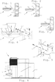
- The invention will now be described with reference to the schematic drawings, wherein:
-
Figures 1 to 3 illustrate a connection sequence of a machine body or frame with a first connection part and a recipient support with a second connection part of a machine according to the invention; -
Figure 4 illustrates in greater details the recipient support connected to the machine body or frame in the state shown inFig. 3 ; -
Figure 5 illustrates in greater details the connection between the recipient support and the machine body or frame shown inFig. 4 ; and -
Figure 6 illustrates the machine according to the invention with the machine body or frame and the recipient support shown inFigs 3 to 5 . -
Figures 1 to 6 illustrate an exemplary embodiment of amachine 1 according to the invention and parts thereof. InFig. 6 ,machine 1 is in position for dispensing a beverage 2. - In
such machine 1, beverage 2 may be prepared from a receptacle containing a beverage ingredient and/or from loose beverage ingredient(s). -
Machine 1 has abeverage outlet 3 that is located above a dispensingarea 4.Machine 1 includes a body orframe 5 having a first connectingpart 51 and bearingbeverage outlet 3.Machine 1 comprises arecipient support 6 having a second connectingpart 61 and asupport member 62 held, directly or indirectly, by second connectingpart 61. - Second connecting
part 61 is disconnectably connectable to first connectingpart 51 so thatsupport member 62 extends into dispensingarea 4 to support a beverage user-recipient 7 underbeverage outlet 3. First connectingpart 51 and second connectingpart 61 have a connection member and a connection receiver arrangement, e.g. a plug and socket arrangement, for disconnectably connectingparts part 51 forms a connection receiver and second connectingpart 61 forms a connection member. - The connection member is inserted in the connection receiver when first and second connecting
parts Figs 3 to 6 ). The connection member is removed from the connection receiver along a removal direction 51' when the first and second connectingparts Figs 1 and 4 ). - Removal direction 51' has an upwardly directed
vertical component 51" when such machine is in position to dispense beverage 2 (Fig. 4 and 5 ). Typically, in such a position,machine 1 is placed with a machine bottom 50 on an external generally horizontal support surface 8 (Fig. 6 ). - Upwardly directed
vertical component 51" of removal direction 51' can be opposite to a vertical component of aforce 71 exercised by user-recipient 7 onsupport member 62 when placed thereon under beverage outlet 3 (Fig. 4 ). - The connection member can be in the shape generally of a rod or a bar extending along removal direction 51' when first and second connecting
parts Figs 1 to 4 ). - The connection receiver and/or the connection member can have a
connection approaching extremity insertion aperture 51a of the connection receiver or afree end 61a of the connection member, that allows for a mechanical positioning play between the connection member and the connection receiver when approaching each other at insertion (Figs 1, 2 and 5 ). Approachingextremity Fig. 5 ). The receiverconnection approaching extremity 51a may be flared and the memberconnection approaching extremity 61a may be tapered (Fig. 5 ). -
Connection approaching extremity extremity play portion extremity urging portion main urging force 51‴,51ʺʺ is exercised by first connectingpart 51 on second connectingpart 61 when second connectingpart 61 is connected to first connecting part 51 (Fig. 5 ). First connectingpart 51 may exercise a first main urgingforce 51‴ atconnection approaching extremity 61a and a second main urgingforce 51"" at an extremity opposite thereto (Fig. 5 ). - The connection member and the connection receiver can be secured in a cantilever manner by gravity force of
support member 62 whensuch machine 1 is in position to dispense beverage 2: a or the abovefree end 61a of the connection member in the connection receiver is urged down (seearrow 51‴ inFig. 5 ) by the connection receiver and a or theabove insertion aperture 51a of the connection receiver urges up (seearrow 51"" inFig. 5 ) a or the extremity in the connection receiver of the connection member oppositefree end 61a. -
Free end 61a and the extremity of the connection member oppositefree end 61a can be further urged bygravity force 71 of beverage user-recipient 7 placed onsupport member 62. - The connection receiver and/or the connection member may have a or the above
connection approaching extremity above insertion aperture 51a of the connection receiver or a or the abovefree end 61a of the connection member, that allows for a mechanical positioning play between the connection member and the connection receiver at insertion. For example, approachingextremity connection approaching extremity 51a is flared and the memberconnection approaching extremity 61a is tapered. - In vertical cross-section extending along removal direction 51', the connection member within the connection receiver may have a convex shape and/or the connection receiver around the connection member may have a concave shape, the connection member and the connection receiver being for instance connectable together by a hook-free connection.
- The connection member can have a shape extending all along within the connection receiver generally straight or arched along removal direction 51' when first and second connecting
parts - The connection member and the connection receiver may cooperate along a plain or roller bearing interface to connect and disconnect the member and the receiver.
- The connection member and the connection receiver may be clamped together when first and
second parts -
Support member 62 may have a recipient placement surface 62' for placingrecipient 7 thereon underbeverage outlet 3. Removal direction 51' can be angled away upwardly from a horizontal direction by an angle α in a range of 5 to 80 deg. such as 10 to 60 deg., for instance 15 to 45 deg., e.g. 25 to 35 deg., when first and second connectingparts such machine 1 is in position to dispense beverage 2. SeeFigs 4 and 5 . - Machine body or
frame 5 can have a plurality of first connectingparts 51 that are vertically spaced apart for allowingrecipient support 6 to be connected via its second connectingpart 61 selectively at different corresponding heights under beverage outlet 3 (Figs 1 to 3 ). - For example,
recipient support 6 has adrop collection arrangement 63 for collecting drops fromsupport member 62. SeeFig. 4 . - Collecting
arrangement 63 may form a liquid reservoir for accumulating drops or a drain channel for evacuating drops e.g. to a service unit ofmachine 1. - Collecting
arrangement 63 can form a member that is separable fromsupport member 62 or that is integral with the support member. - Collecting
arrangement 63 may form a member that is integral with second connectingpart 61. - Collecting
arrangement 63 can be configured to collect drops draining viaopenings 62" ofsupport member 62. -
Machine 1 may include one or more of: a control unit, such as a unit comprising a user-interface, for controlling active machine parts; an ingredient supply arrangement, such as a liquid source, e.g. awater tank 10 and/or a connector to a water supply line; awaste material collector 11, such as a waste ingredient collector and/or a waste ingredient receptacle collector; a fluid circuit, such as a circuit for guiding a fluid, e.g. water, from aliquid source 10 to thebeverage outlet 3. - Such fluid circuit may incorporate a thermal conditioner, e.g. a heater and/or a cooler. Fluid circuit may include a pump, e.g. a solenoid pump or a membrane pump or a peristaltic pump, such as a low pressure pump e.g. operating within a range of 1 to 5 bar, such as 1.5 to 3 bar.
- Such fluid circuit may include an
ingredient mixing unit 12 for producing beverage 2 and delivering such beverage 2 tobeverage outlet 3. For example, mixingunit 12 is configured for mixing liquid fromsource 10 with a flavouring ingredient, e.g. a flavouring ingredient supplied within a or the above receptacle into mixingunit 12. Mixingunit 12 may be arranged for mixing the liquid with the flavouring ingredient by rotational forces, e.g. by rotating mixingunit 12 when containing the liquid and the flavouring ingredient.
Claims (15)
- A machine (1) for dispensing a beverage (2), such as a beverage prepared from a receptacle containing a beverage ingredient, comprising:- a beverage outlet (3) that is located above a dispensing area (4);- a machine body or frame (5) having a first connecting part (51) and bearing the beverage outlet (3); and- a recipient support (6) having a second connecting part (61) and a support member (62) held, directly or indirectly, by the second connecting part (61),the second connecting part (61) being disconnectably connectable to the first connecting part (51) so that the support member (62) extends into the dispensing area (4) to support a beverage user-recipient (7) under the beverage outlet (3), the first connecting part (51) and the second connecting part (61) having a connection member and a connection receiver arrangement, e.g. forming a plug and socket arrangement, for disconnectably connecting the parts (51,61) such that:- the first connecting part forms a connection member and the second connecting part forms a connection receiver; or- the first connecting part (51) forms a connection receiver and the second connecting part (61) forms a connection member,the connection member being inserted in the connection receiver when the first and second connecting parts (51,61) are connected, the connection member being removed from the connection receiver along a removal direction (51') when the first and second connecting parts (51,61) are disconnected,the removal direction (51') having an upwardly directed vertical component (51'') when such machine (1) is in position to dispense said beverage (2), such as placed with a machine bottom (50) on an external generally horizontal support surface (8),wherein, by gravity force of the support member (62) when such machine (1) is in position to dispense said beverage (2), a free end (61a) of the connection member in the connection receiver is urged down (51‴) by the connection receiver,characterised in that, by said gravity force of the support member (62), an insertion aperture (51a) of the connection receiver urges up (51"") an extremity in the connection receiver of the connection member opposite the free end (61a), whereby the connection member and the connection receiver are secured in a cantilever manner.
- The machine of claim 1, wherein the upwardly directed vertical component (51") of the removal direction (51') is opposite to a vertical component of a force (71) exercised by said user-recipient (7) on the support member (62) when placed thereon under the beverage outlet (3).
- The machine of any preceding claim, wherein:- the connection member is in the shape generally of a rod or a bar extending along the removal direction (51') when the first and second connecting parts (51,61) are connected; and- the connection receiver has a corresponding shape such that the connection member can be slid in an out of the connection receiver.
- The machine of any preceding claim, wherein the connection receiver and/or the connection member has a connection approaching extremity (51a,61a), such as a or said insertion aperture (51a) of the connection receiver or a or said free end (61a) of the connection member, that allows for a mechanical positioning play between the connection member and the connection receiver when approaching each other at insertion, for instance the approaching extremity (51a,61a) being tapered or flared, e.g. rounded or bevelled, to facilitate insertion of the connection member into the connection receiver, optionally the receiver connection approaching extremity (51a) being flared and the member connection approaching extremity (61a) being tapered.
- The machine of claim 4, wherein the connection approaching extremity (51a, 61a) is asymmetric to provide a mechanical positioning play only on an extremity play portion (51b,61b) generally opposite to an extremity urging portion (51c,61c) against which a main urging force (51‴,51ʺʺ) is exercised by the first connecting part (51) on the second connecting part (61) when the second connecting part (61) is connected to the first connecting part (51).
- The machine of claim 5, wherein the first connecting part (51) exercises a first main urging force (51‴) at the connection approaching extremity (61a) and a second main urging force (51"") at an extremity opposite thereto.
- The machine of any preceding claim, wherein a or said free end (61a) and the extremity of the connection member opposite the free end (61a) are further urged by gravity force (71) of said beverage user-recipient (7) placed on the support member (62).
- The machine of any one of claims 3 to 7, wherein the connection receiver and/or the connection member has a or said connection approaching extremity (51a,61a), such as a or said insertion aperture (51a) of the connection receiver or a or said free end (61a) of the connection member, that allows for a mechanical positioning play between the connection member and the connection receiver at insertion, for instance the approaching extremity (51a,61a) being tapered or flared, e.g. rounded or bevelled, to facilitate insertion of the connection member into the connection receiver, optionally the receiver connection approaching extremity (51a) being flared and the member connection approaching extremity (61a) being tapered.
- The machine of any preceding claim, wherein, in vertical cross-section extending along the removal direction (51'), the connection member within the connection receiver has a convex shape or the connection receiver around the connection member has a concave shape, the connection member and the connection receiver being for instance connectable together by a hook-free connection.
- The machine of any preceding claim, wherein the connection member has a shape extending all along within the connection receiver generally straight or arched along the removal direction (51') when the first and second connecting parts (51,61) are connected, optionally the connection receiver having a corresponding shape.
- The machine of any preceding claim, wherein the connection member and the connection receiver:- cooperate along a plain or roller bearing interface to connect and disconnect the member and the receiver; and/or- are clamped together when the first and second parts (51,61) are connected together.
- The machine of any preceding claim, wherein the support member (62) has a recipient placement surface (62') for placing said recipient (7) thereon under the beverage outlet (3) and wherein the removal direction (51') is angled away upwardly from a horizontal direction by an angle (α) in a range of 5 to 80 deg. such as 10 to 60 deg., for instance 15 to 45 deg., e.g. 25 to 35 deg., when the first and second connecting parts (51,61) are connected and such machine (1) is in position to dispense said beverage (2).
- The machine of any preceding claim, wherein the machine body or frame (5) has a plurality of first connecting parts (51) that are vertically spaced apart for allowing the recipient support (6) to be connected via its second connecting part (61) selectively at different corresponding heights under the beverage outlet (3) .
- The machine of any preceding claim, wherein the recipient support (6) has a drop collection arrangement (63) for collecting drops from the support member (62), optionally the collecting arrangement (63):- forming a liquid reservoir for accumulating drops or a drain channel for evacuating drops e.g. to a service unit of such machine (1);- forming a member that is separable from the support member (62) or that is integral with the support member;- forming a member that is integral with the second connecting part (61); and/or- being configured to collect drops draining via openings (62") of the support member (62).
- The machine of any preceding claim, which comprises one or more of: a control unit, such as a unit comprising a user-interface, for controlling active machine parts; an ingredient supply arrangement, such as a liquid source, e.g. a water tank (10) and/or a connector to a water supply line; a waste material collector (11), such as a waste ingredient collector and/or a waste ingredient receptacle collector; a fluid circuit, such as a circuit for guiding a fluid, e.g. water, from a liquid source (10) to the beverage outlet (3) via one or more of:- a thermal conditioner, e.g. a heater and/or a cooler;- a pump, e.g. a solenoid pump or a membrane pump or a peristaltic pump, such as a low pressure pump e.g. operating within a range of 1 to 5 bar, such as 1.5 to 3 bar; and- an ingredient mixing unit (12) for producing said beverage (2) and delivering such beverage (2) to the beverage outlet (3), for instance a unit for mixing liquid from the source (10) with a flavouring ingredient, e.g. a flavouring ingredient supplied within said receptacle into the mixing unit (12), such as a unit (12) for mixing the liquid with the flavouring ingredient by rotational forces, e.g. by rotating the mixing unit (12) when containing the liquid and the flavouring ingredient.
Applications Claiming Priority (2)
| Application Number | Priority Date | Filing Date | Title |
|---|---|---|---|
| EP18188315 | 2018-08-09 | ||
| PCT/EP2019/071324 WO2020030740A1 (en) | 2018-08-09 | 2019-08-08 | Easily insertable cup support |
Publications (2)
| Publication Number | Publication Date |
|---|---|
| EP3833227A1 EP3833227A1 (en) | 2021-06-16 |
| EP3833227B1 true EP3833227B1 (en) | 2024-11-13 |
Family
ID=63207656
Family Applications (1)
| Application Number | Title | Priority Date | Filing Date |
|---|---|---|---|
| EP19752486.1A Active EP3833227B1 (en) | 2018-08-09 | 2019-08-08 | Easily insertable cup support |
Country Status (9)
| Country | Link |
|---|---|
| US (1) | US12070150B2 (en) |
| EP (1) | EP3833227B1 (en) |
| JP (1) | JP7504867B2 (en) |
| CN (1) | CN112512390B (en) |
| AU (1) | AU2019318450B2 (en) |
| CA (1) | CA3108829A1 (en) |
| ES (1) | ES3003917T3 (en) |
| PT (1) | PT3833227T (en) |
| WO (1) | WO2020030740A1 (en) |
Families Citing this family (5)
| Publication number | Priority date | Publication date | Assignee | Title |
|---|---|---|---|---|
| US11608259B2 (en) * | 2018-08-27 | 2023-03-21 | LNJ Group, LLC | Beverage dispensing machine and pouch for use with beverage dispensing machine |
| US20240245255A1 (en) * | 2021-05-26 | 2024-07-25 | Breville Pty Limited | Coffee machine and milk texturing device |
| EP4412496A1 (en) | 2021-10-08 | 2024-08-14 | Société des Produits Nestlé S.A. | Beverage preparation machine with simple ergonomic opening-closure |
| EP4415588A1 (en) | 2021-10-13 | 2024-08-21 | Société des Produits Nestlé S.A. | Ergonomic beverage machine |
| GB202209989D0 (en) * | 2022-07-07 | 2022-08-24 | Schaal Marc | Container-based system for preparing and dispensing a custom beverage |
Citations (2)
| Publication number | Priority date | Publication date | Assignee | Title |
|---|---|---|---|---|
| DE202012006928U1 (en) * | 2012-07-18 | 2012-08-23 | Eugster/Frismag Ag | Beverage preparation device, in particular espresso machine, with a height-adjustable collecting container carrier |
| EP2323523B1 (en) * | 2008-09-17 | 2012-10-10 | BSH Bosch und Siemens Hausgeräte GmbH | Holder device |
Family Cites Families (81)
| Publication number | Priority date | Publication date | Assignee | Title |
|---|---|---|---|---|
| US2715868A (en) | 1951-11-23 | 1955-08-23 | Internat Coffee Corp | Coffee extracting and dispensing apparatus |
| US5161455A (en) | 1991-05-15 | 1992-11-10 | Bunn-O-Matic Corporation | Combination coffee and tea brewer |
| IT1252633B (en) | 1991-12-05 | 1995-06-19 | Gianmauro Zani | COMPACT COFFEE MACHINE FOR ESPRESSO COFFEE AND HOT WATER FALL COFFEE FOR FILTRATION OTHERWISE KNOWN AS AMERICAN COFFEE. |
| DE4234746A1 (en) | 1992-10-15 | 1994-04-21 | Braun Ag | Pump for household appliances |
| US5353692A (en) | 1993-09-29 | 1994-10-11 | Unidynamics Corporation | Hot beverage brewing apparatus |
| FR2721381B1 (en) | 1994-06-20 | 1996-08-02 | Seb Sa | Device for producing hot water or steam. |
| AU713251B2 (en) | 1995-12-28 | 1999-11-25 | Creaholic S.A. | Coffee machine |
| IT246634Y1 (en) | 1999-04-09 | 2002-04-09 | Ulka Srl | COMPOSITE PISTON FOR VIBRATION PUMP |
| US6459854B1 (en) | 2000-01-24 | 2002-10-01 | Nestec S.A. | Process and module for heating liquid |
| DE60227248D1 (en) | 2002-07-12 | 2008-08-07 | Nestec Sa | Device for heating a liquid |
| GB2397503B (en) | 2003-01-24 | 2005-03-02 | Kraft Foods R & D Inc | Machine for the preparation of beverages |
| NL1023023C2 (en) * | 2003-03-26 | 2004-09-30 | Bravilor Holding Bv | Device for preparing hot water. |
| EP1634520A1 (en) | 2004-09-13 | 2006-03-15 | Nestec S.A. | Device and method for heating a liquid |
| DE102004046435A1 (en) | 2004-09-24 | 2006-04-27 | BSH Bosch und Siemens Hausgeräte GmbH | Coffee machine and pump holder for a coffee machine |
| PL1656863T3 (en) | 2004-11-11 | 2011-07-29 | Nestec Sa | Self-cleaning mixing head for producing a milk-based mixture and beverage production machines comprising such a mixing head |
| EP1943931B1 (en) | 2005-06-07 | 2009-08-26 | Nestec S.A. | Froth dispenser with milk vessel, disposable nozzle and drip tray device for recipients of different heights |
| ATE474488T1 (en) * | 2005-12-15 | 2010-08-15 | Koninkl Philips Electronics Nv | DRINK PREPARATION MACHINE WITH A LIQUID LEVEL SENSOR |
| ATE442798T1 (en) | 2006-05-24 | 2009-10-15 | Nestec Sa | BREWING DEVICE FOR CAPSULES WITH CLOSING MECHANISM WITH VARIABLE GEAR RATIO |
| DE602006014521D1 (en) | 2006-06-16 | 2010-07-08 | Nestec Sa | Vending machine with support system and drip catcher for containers of different sizes |
| AU2008258543B2 (en) | 2007-06-05 | 2014-04-10 | Société des Produits Nestlé S.A. | Capsule and method for preparing a food liquid by centrifugation |
| DE602007008213D1 (en) | 2007-06-05 | 2010-09-16 | Nestec Sa | Process for making a beverage or liquid food and system using brewing centrifugal force |
| ATE503408T1 (en) | 2007-06-05 | 2011-04-15 | Nestec Sa | CAPSULE SYSTEM, DEVICE AND METHOD FOR PRODUCING A LIQUID FOOD IN A CONTAINER USING CENTRIFUGATION |
| PT2152607E (en) | 2007-06-05 | 2012-02-03 | Nestec Sa | Single-use capsule for preparing a food liquid by centrifugation |
| EP2155019B1 (en) | 2007-06-05 | 2011-04-06 | Nestec S.A. | Method for preparing a beverage or liquid food |
| ITFI20070172A1 (en) | 2007-07-24 | 2009-01-25 | Saeco Ipr Ltd | "A SUPPORT FOR CUPS OR OTHER CONTAINERS IN DRINK MACHINES" |
| EP2027798A1 (en) | 2007-08-20 | 2009-02-25 | Nestec S.A. | Beverage production module and method for operating a beverage production module |
| WO2009074559A1 (en) | 2007-12-12 | 2009-06-18 | Nestec S.A. | Used capsule or pod receptacle for liquid food or beverage machines |
| EP2070454B1 (en) | 2007-12-12 | 2015-07-15 | Nestec S.A. | Beverage production machines comprising a plurality of core units |
| WO2009106589A1 (en) | 2008-02-26 | 2009-09-03 | Mann+Hummel Gmbh | Multiple bellow-type filter with increased efficiency |
| CN101959445B (en) | 2008-02-29 | 2014-02-26 | 雀巢产品技术援助有限公司 | Apparatus and method for preparing a beverage by centrifugation |
| JP2011518015A (en) | 2008-04-22 | 2011-06-23 | ネステク ソシエテ アノニム | Module assembly for beverage production equipment |
| ES2430589T3 (en) | 2008-05-07 | 2013-11-21 | Nestec S.A. | Capsule collector used for beverage preparation device |
| JP5457436B2 (en) | 2008-05-28 | 2014-04-02 | ネステク ソシエテ アノニム | Pump for liquid beverage preparation equipment |
| DK2317898T3 (en) | 2008-07-14 | 2012-10-15 | Nestec Sa | WATER CIRCULATION SYSTEM FOR A DRINK PREPARATION DEVICE |
| RU2492788C2 (en) | 2008-09-02 | 2013-09-20 | Нестек С.А. | Controllable device for preparation of beverages using centrifugal forces |
| EP2330953B1 (en) | 2008-09-02 | 2015-06-03 | Nestec S.A. | Method for preparing a food liquid contained in a capsule by centrifugation and system adapted for such method |
| US8962048B2 (en) | 2008-12-03 | 2015-02-24 | Nestec S.A. | Capsule for the preparation of a beverage by centrifugation |
| CN102245066B (en) | 2008-12-09 | 2014-01-15 | 雀巢产品技术援助有限公司 | Liquid food preparation system for preparing a liquid food by centrifugation |
| KR101648233B1 (en) | 2008-12-09 | 2016-08-12 | 네스텍 소시에테아노님 | Capsule for preparing a beverage by centrifugation in a beverage preparation device and device adapted therefore |
| JP5643771B2 (en) | 2009-02-06 | 2014-12-17 | ネステク ソシエテ アノニム | Apparatus and method using centrifugal separation and heat loss compensation means for liquid extraction |
| EP2228633B1 (en) | 2009-03-10 | 2017-07-05 | Nestec S.A. | Optical level detector for a beverage machine |
| PT2410894E (en) | 2009-03-23 | 2014-05-02 | Nestec Sa | Pump mount in a beverage preparation machine |
| BRPI1011187A2 (en) | 2009-05-06 | 2016-03-15 | Nestec Sa | beverage machines with simplified assistance. |
| IN2012DN00761A (en) | 2009-08-28 | 2015-05-22 | Nestec Sa | |
| US9084511B2 (en) * | 2009-10-22 | 2015-07-21 | Bunn-O-Matic Corporation | Flexible spray head |
| WO2011083103A2 (en) | 2010-01-06 | 2011-07-14 | Nestec S.A. | Vibration proof water tank of a beverage machine |
| PL2523587T3 (en) | 2010-01-15 | 2014-03-31 | Nestec Sa | Ergonomic service unit for beverage preparation machines |
| PT2523586E (en) | 2010-01-15 | 2014-09-09 | Nestec Sa | Ergonomic ingredient holder and service unit coordination |
| PT2525693E (en) | 2010-01-21 | 2014-07-16 | Nestec Sa | Beverage machine with removable liquid supply reservoir |
| JP2011167469A (en) * | 2010-02-22 | 2011-09-01 | Makoto Takagi | Coffee extractor and coffee extraction method |
| US20120328456A1 (en) | 2010-03-05 | 2012-12-27 | Nestec S.A. | Reduction of pump nuisance |
| BR112012031401A2 (en) | 2010-06-09 | 2016-11-08 | Nestec Sa | ergonomic beverage machine service arrangement |
| CN103002783B (en) | 2010-07-12 | 2016-08-17 | 雀巢产品技术援助有限公司 | Firm cup supporting member for beverage machine |
| EP2645914B1 (en) | 2010-12-01 | 2016-07-13 | Nestec S.A. | Beverage preparation machine with drop collector |
| EP2474254A1 (en) | 2011-01-07 | 2012-07-11 | Nestec S.A. | Modular beverage dispensing system |
| EP2790554A2 (en) * | 2011-12-12 | 2014-10-22 | Nestec S.A. | Drip tray for beverages dispenser |
| DE202011052332U1 (en) * | 2011-12-16 | 2013-03-19 | Wik Far East Ltd. | Storage container for storing a liquid food, such as milk |
| PT2797465E (en) | 2011-12-30 | 2015-10-06 | Nestec Sa | A multi-system beverage machine |
| EP2633789A1 (en) | 2012-02-28 | 2013-09-04 | Nestec S.A. | Beverage preparation machine with drop management |
| IN2014DN10125A (en) | 2012-06-15 | 2015-08-21 | Nestec Sa | |
| US10010210B2 (en) | 2012-12-20 | 2018-07-03 | Nestec S.A. | Double ramp for closing a receptacle holder |
| WO2014096122A1 (en) | 2012-12-20 | 2014-06-26 | Nestec S.A. | Variable transmission for closing a receptacle holder |
| DE102013010110A1 (en) | 2013-06-18 | 2014-12-18 | Beem Blitz-Elektro-Erzeugnisse Manufaktur Handels-Gmbh | coffee machine |
| US10231573B2 (en) | 2013-12-23 | 2019-03-19 | Nestec S.A. | Simple ergonomic user-interface for a beverage machine |
| PT3166456T (en) | 2014-07-09 | 2019-01-11 | Nestle Sa | Accessory for supplying automatically a beverage machine with liquid from a distribution network |
| ES2875040T3 (en) | 2014-07-09 | 2021-11-08 | Nestle Sa | Coupling of a device to connect a beverage machine to a distribution network |
| WO2016005350A1 (en) | 2014-07-09 | 2016-01-14 | Nestec S.A. | Device for connecting a beverage machine to a distribution network with safe monitoring |
| PT3166455T (en) | 2014-07-09 | 2020-11-20 | Nestle Sa | Device for connecting a beverage machine to a distribution network with safe flow interruption |
| US11241115B2 (en) | 2014-12-18 | 2022-02-08 | Societe Des Produits Nestle S.A. | Beverage machine with slidingly connectable cup-support |
| ES2777548T3 (en) | 2014-12-18 | 2020-08-05 | Société des Produits Nestlé SA | Self-positioning cup holder beverage machine |
| CN107105930B (en) | 2014-12-18 | 2021-09-07 | 雀巢产品有限公司 | Removable Cup Support Platform on Collector Receiver |
| US9844293B2 (en) * | 2015-03-06 | 2017-12-19 | Spectrum Brands, Inc. | Apparatus for dispensing beverages |
| CN107405022B (en) * | 2015-03-09 | 2019-11-15 | 雀巢产品有限公司 | Automated fluid injection head for beverage preparation equipment |
| ES2812774T3 (en) | 2015-04-02 | 2021-03-18 | Nestle Sa | Sliding cup holder |
| WO2016156368A1 (en) | 2015-04-02 | 2016-10-06 | Nestec S.A. | Locking cup support |
| ES2970243T3 (en) | 2015-04-02 | 2024-05-27 | Nestle Sa | deep machine |
| EP3349620B1 (en) | 2015-09-18 | 2021-01-06 | Société des Produits Nestlé S.A. | Removal of a capsule from a capsule holder |
| EP3213662A1 (en) * | 2016-03-02 | 2017-09-06 | Nestec S.A. | Beverage machine |
| US10939780B2 (en) * | 2016-03-17 | 2021-03-09 | Eugster / Frismag Ag | Beverage preparation device and operating method |
| CN105686642B (en) * | 2016-04-22 | 2019-01-29 | 施钟毓 | Coffee machine equipments with more storehouse capsule seats |
| EP3463004B1 (en) | 2016-05-23 | 2023-11-22 | Société des Produits Nestlé S.A. | Removal of a capsule from a capsule holder |
-
2019
- 2019-08-08 JP JP2021505960A patent/JP7504867B2/en active Active
- 2019-08-08 ES ES19752486T patent/ES3003917T3/en active Active
- 2019-08-08 CN CN201980047132.0A patent/CN112512390B/en active Active
- 2019-08-08 CA CA3108829A patent/CA3108829A1/en active Pending
- 2019-08-08 WO PCT/EP2019/071324 patent/WO2020030740A1/en not_active Ceased
- 2019-08-08 PT PT197524861T patent/PT3833227T/en unknown
- 2019-08-08 AU AU2019318450A patent/AU2019318450B2/en active Active
- 2019-08-08 US US17/266,199 patent/US12070150B2/en active Active
- 2019-08-08 EP EP19752486.1A patent/EP3833227B1/en active Active
Patent Citations (2)
| Publication number | Priority date | Publication date | Assignee | Title |
|---|---|---|---|---|
| EP2323523B1 (en) * | 2008-09-17 | 2012-10-10 | BSH Bosch und Siemens Hausgeräte GmbH | Holder device |
| DE202012006928U1 (en) * | 2012-07-18 | 2012-08-23 | Eugster/Frismag Ag | Beverage preparation device, in particular espresso machine, with a height-adjustable collecting container carrier |
Also Published As
| Publication number | Publication date |
|---|---|
| US12070150B2 (en) | 2024-08-27 |
| ES3003917T3 (en) | 2025-03-11 |
| EP3833227A1 (en) | 2021-06-16 |
| JP2021532921A (en) | 2021-12-02 |
| JP7504867B2 (en) | 2024-06-24 |
| CN112512390A (en) | 2021-03-16 |
| CA3108829A1 (en) | 2020-02-13 |
| US20210251419A1 (en) | 2021-08-19 |
| PT3833227T (en) | 2025-01-16 |
| CN112512390B (en) | 2023-08-25 |
| AU2019318450B2 (en) | 2024-11-21 |
| WO2020030740A1 (en) | 2020-02-13 |
| AU2019318450A1 (en) | 2021-01-07 |
Similar Documents
| Publication | Publication Date | Title |
|---|---|---|
| US12070150B2 (en) | Easily insertable cup support | |
| US9675205B2 (en) | Beverage machine for short and tall cups | |
| EP3232875B1 (en) | Beverage machine with slidingly connectable cup-support | |
| EP2861109B1 (en) | Beverage machine with vibration inhibitor | |
| EP3232877B1 (en) | Beverage machine with self-positioning cup-support | |
| EP2802245B1 (en) | Beverage machine with a removable module | |
| US11272805B2 (en) | Removable cup support platform on collector receptacle | |
| US10939779B2 (en) | Shallow machine | |
| EP4076107A1 (en) | Beverage machine with actuated water supply valve | |
| RU2799353C2 (en) | Insertable cup rack | |
| US20230027842A1 (en) | Beverage machine with separable beverage processing unit | |
| WO2021122494A1 (en) | Beverage machine with simple water driving |
Legal Events
| Date | Code | Title | Description |
|---|---|---|---|
| STAA | Information on the status of an ep patent application or granted ep patent |
Free format text: STATUS: UNKNOWN |
|
| STAA | Information on the status of an ep patent application or granted ep patent |
Free format text: STATUS: THE INTERNATIONAL PUBLICATION HAS BEEN MADE |
|
| PUAI | Public reference made under article 153(3) epc to a published international application that has entered the european phase |
Free format text: ORIGINAL CODE: 0009012 |
|
| STAA | Information on the status of an ep patent application or granted ep patent |
Free format text: STATUS: REQUEST FOR EXAMINATION WAS MADE |
|
| 17P | Request for examination filed |
Effective date: 20210309 |
|
| AK | Designated contracting states |
Kind code of ref document: A1 Designated state(s): AL AT BE BG CH CY CZ DE DK EE ES FI FR GB GR HR HU IE IS IT LI LT LU LV MC MK MT NL NO PL PT RO RS SE SI SK SM TR |
|
| DAV | Request for validation of the european patent (deleted) | ||
| DAX | Request for extension of the european patent (deleted) | ||
| P01 | Opt-out of the competence of the unified patent court (upc) registered |
Effective date: 20230527 |
|
| GRAP | Despatch of communication of intention to grant a patent |
Free format text: ORIGINAL CODE: EPIDOSNIGR1 |
|
| STAA | Information on the status of an ep patent application or granted ep patent |
Free format text: STATUS: GRANT OF PATENT IS INTENDED |
|
| INTG | Intention to grant announced |
Effective date: 20240611 |
|
| GRAS | Grant fee paid |
Free format text: ORIGINAL CODE: EPIDOSNIGR3 |
|
| GRAA | (expected) grant |
Free format text: ORIGINAL CODE: 0009210 |
|
| STAA | Information on the status of an ep patent application or granted ep patent |
Free format text: STATUS: THE PATENT HAS BEEN GRANTED |
|
| AK | Designated contracting states |
Kind code of ref document: B1 Designated state(s): AL AT BE BG CH CY CZ DE DK EE ES FI FR GB GR HR HU IE IS IT LI LT LU LV MC MK MT NL NO PL PT RO RS SE SI SK SM TR |
|
| REG | Reference to a national code |
Ref country code: GB Ref legal event code: FG4D |
|
| REG | Reference to a national code |
Ref country code: CH Ref legal event code: EP |
|
| REG | Reference to a national code |
Ref country code: IE Ref legal event code: FG4D |
|
| REG | Reference to a national code |
Ref country code: DE Ref legal event code: R096 Ref document number: 602019061945 Country of ref document: DE |
|
| REG | Reference to a national code |
Ref country code: PT Ref legal event code: SC4A Ref document number: 3833227 Country of ref document: PT Date of ref document: 20250116 Kind code of ref document: T Free format text: AVAILABILITY OF NATIONAL TRANSLATION Effective date: 20250110 |
|
| REG | Reference to a national code |
Ref country code: NL Ref legal event code: FP |
|
| REG | Reference to a national code |
Ref country code: LT Ref legal event code: MG9D |
|
| REG | Reference to a national code |
Ref country code: ES Ref legal event code: FG2A Ref document number: 3003917 Country of ref document: ES Kind code of ref document: T3 Effective date: 20250311 |
|
| PG25 | Lapsed in a contracting state [announced via postgrant information from national office to epo] |
Ref country code: IS Free format text: LAPSE BECAUSE OF FAILURE TO SUBMIT A TRANSLATION OF THE DESCRIPTION OR TO PAY THE FEE WITHIN THE PRESCRIBED TIME-LIMIT Effective date: 20250313 Ref country code: HR Free format text: LAPSE BECAUSE OF FAILURE TO SUBMIT A TRANSLATION OF THE DESCRIPTION OR TO PAY THE FEE WITHIN THE PRESCRIBED TIME-LIMIT Effective date: 20241113 |
|
| PG25 | Lapsed in a contracting state [announced via postgrant information from national office to epo] |
Ref country code: FI Free format text: LAPSE BECAUSE OF FAILURE TO SUBMIT A TRANSLATION OF THE DESCRIPTION OR TO PAY THE FEE WITHIN THE PRESCRIBED TIME-LIMIT Effective date: 20241113 |
|
| PG25 | Lapsed in a contracting state [announced via postgrant information from national office to epo] |
Ref country code: BG Free format text: LAPSE BECAUSE OF FAILURE TO SUBMIT A TRANSLATION OF THE DESCRIPTION OR TO PAY THE FEE WITHIN THE PRESCRIBED TIME-LIMIT Effective date: 20241113 |
|
| PG25 | Lapsed in a contracting state [announced via postgrant information from national office to epo] |
Ref country code: NO Free format text: LAPSE BECAUSE OF FAILURE TO SUBMIT A TRANSLATION OF THE DESCRIPTION OR TO PAY THE FEE WITHIN THE PRESCRIBED TIME-LIMIT Effective date: 20250213 |
|
| PG25 | Lapsed in a contracting state [announced via postgrant information from national office to epo] |
Ref country code: GR Free format text: LAPSE BECAUSE OF FAILURE TO SUBMIT A TRANSLATION OF THE DESCRIPTION OR TO PAY THE FEE WITHIN THE PRESCRIBED TIME-LIMIT Effective date: 20250214 Ref country code: LV Free format text: LAPSE BECAUSE OF FAILURE TO SUBMIT A TRANSLATION OF THE DESCRIPTION OR TO PAY THE FEE WITHIN THE PRESCRIBED TIME-LIMIT Effective date: 20241113 |
|
| PG25 | Lapsed in a contracting state [announced via postgrant information from national office to epo] |
Ref country code: PL Free format text: LAPSE BECAUSE OF FAILURE TO SUBMIT A TRANSLATION OF THE DESCRIPTION OR TO PAY THE FEE WITHIN THE PRESCRIBED TIME-LIMIT Effective date: 20241113 |
|
| PG25 | Lapsed in a contracting state [announced via postgrant information from national office to epo] |
Ref country code: RS Free format text: LAPSE BECAUSE OF FAILURE TO SUBMIT A TRANSLATION OF THE DESCRIPTION OR TO PAY THE FEE WITHIN THE PRESCRIBED TIME-LIMIT Effective date: 20250213 |
|
| PG25 | Lapsed in a contracting state [announced via postgrant information from national office to epo] |
Ref country code: SM Free format text: LAPSE BECAUSE OF FAILURE TO SUBMIT A TRANSLATION OF THE DESCRIPTION OR TO PAY THE FEE WITHIN THE PRESCRIBED TIME-LIMIT Effective date: 20241113 |
|
| PG25 | Lapsed in a contracting state [announced via postgrant information from national office to epo] |
Ref country code: DK Free format text: LAPSE BECAUSE OF FAILURE TO SUBMIT A TRANSLATION OF THE DESCRIPTION OR TO PAY THE FEE WITHIN THE PRESCRIBED TIME-LIMIT Effective date: 20241113 |
|
| PG25 | Lapsed in a contracting state [announced via postgrant information from national office to epo] |
Ref country code: EE Free format text: LAPSE BECAUSE OF FAILURE TO SUBMIT A TRANSLATION OF THE DESCRIPTION OR TO PAY THE FEE WITHIN THE PRESCRIBED TIME-LIMIT Effective date: 20241113 |
|
| PG25 | Lapsed in a contracting state [announced via postgrant information from national office to epo] |
Ref country code: RO Free format text: LAPSE BECAUSE OF FAILURE TO SUBMIT A TRANSLATION OF THE DESCRIPTION OR TO PAY THE FEE WITHIN THE PRESCRIBED TIME-LIMIT Effective date: 20241113 |
|
| PG25 | Lapsed in a contracting state [announced via postgrant information from national office to epo] |
Ref country code: SK Free format text: LAPSE BECAUSE OF FAILURE TO SUBMIT A TRANSLATION OF THE DESCRIPTION OR TO PAY THE FEE WITHIN THE PRESCRIBED TIME-LIMIT Effective date: 20241113 |
|
| PG25 | Lapsed in a contracting state [announced via postgrant information from national office to epo] |
Ref country code: CZ Free format text: LAPSE BECAUSE OF FAILURE TO SUBMIT A TRANSLATION OF THE DESCRIPTION OR TO PAY THE FEE WITHIN THE PRESCRIBED TIME-LIMIT Effective date: 20241113 |
|
| REG | Reference to a national code |
Ref country code: DE Ref legal event code: R097 Ref document number: 602019061945 Country of ref document: DE |
|
| PGFP | Annual fee paid to national office [announced via postgrant information from national office to epo] |
Ref country code: NL Payment date: 20250704 Year of fee payment: 7 |
|
| PG25 | Lapsed in a contracting state [announced via postgrant information from national office to epo] |
Ref country code: SE Free format text: LAPSE BECAUSE OF FAILURE TO SUBMIT A TRANSLATION OF THE DESCRIPTION OR TO PAY THE FEE WITHIN THE PRESCRIBED TIME-LIMIT Effective date: 20241113 |
|
| PLBE | No opposition filed within time limit |
Free format text: ORIGINAL CODE: 0009261 |
|
| STAA | Information on the status of an ep patent application or granted ep patent |
Free format text: STATUS: NO OPPOSITION FILED WITHIN TIME LIMIT |
|
| PGFP | Annual fee paid to national office [announced via postgrant information from national office to epo] |
Ref country code: PT Payment date: 20250807 Year of fee payment: 7 Ref country code: ES Payment date: 20250905 Year of fee payment: 7 |
|
| PGFP | Annual fee paid to national office [announced via postgrant information from national office to epo] |
Ref country code: DE Payment date: 20250702 Year of fee payment: 7 |
|
| PGFP | Annual fee paid to national office [announced via postgrant information from national office to epo] |
Ref country code: IT Payment date: 20250722 Year of fee payment: 7 |
|
| PGFP | Annual fee paid to national office [announced via postgrant information from national office to epo] |
Ref country code: BE Payment date: 20250703 Year of fee payment: 7 Ref country code: GB Payment date: 20250703 Year of fee payment: 7 |
|
| PGFP | Annual fee paid to national office [announced via postgrant information from national office to epo] |
Ref country code: FR Payment date: 20250703 Year of fee payment: 7 Ref country code: AT Payment date: 20250725 Year of fee payment: 7 |
|
| PGFP | Annual fee paid to national office [announced via postgrant information from national office to epo] |
Ref country code: CH Payment date: 20250901 Year of fee payment: 7 |
|
| 26N | No opposition filed |
Effective date: 20250814 |
|
| REG | Reference to a national code |
Ref country code: AT Ref legal event code: UEP Ref document number: 1740956 Country of ref document: AT Kind code of ref document: T Effective date: 20241113 |
|
| PG25 | Lapsed in a contracting state [announced via postgrant information from national office to epo] |
Ref country code: MC Free format text: LAPSE BECAUSE OF FAILURE TO SUBMIT A TRANSLATION OF THE DESCRIPTION OR TO PAY THE FEE WITHIN THE PRESCRIBED TIME-LIMIT Effective date: 20241113 |
|
| PG25 | Lapsed in a contracting state [announced via postgrant information from national office to epo] |
Ref country code: LU Free format text: LAPSE BECAUSE OF NON-PAYMENT OF DUE FEES Effective date: 20250808 |