EP3832998A1 - Vehicle-mounted camera - Google Patents
Vehicle-mounted camera Download PDFInfo
- Publication number
- EP3832998A1 EP3832998A1 EP19844820.1A EP19844820A EP3832998A1 EP 3832998 A1 EP3832998 A1 EP 3832998A1 EP 19844820 A EP19844820 A EP 19844820A EP 3832998 A1 EP3832998 A1 EP 3832998A1
- Authority
- EP
- European Patent Office
- Prior art keywords
- plate
- face plate
- face
- shield
- onboard camera
- Prior art date
- Legal status (The legal status is an assumption and is not a legal conclusion. Google has not performed a legal analysis and makes no representation as to the accuracy of the status listed.)
- Granted
Links
Images










Classifications
-
- G—PHYSICS
- G03—PHOTOGRAPHY; CINEMATOGRAPHY; ANALOGOUS TECHNIQUES USING WAVES OTHER THAN OPTICAL WAVES; ELECTROGRAPHY; HOLOGRAPHY
- G03B—APPARATUS OR ARRANGEMENTS FOR TAKING PHOTOGRAPHS OR FOR PROJECTING OR VIEWING THEM; APPARATUS OR ARRANGEMENTS EMPLOYING ANALOGOUS TECHNIQUES USING WAVES OTHER THAN OPTICAL WAVES; ACCESSORIES THEREFOR
- G03B17/00—Details of cameras or camera bodies; Accessories therefor
- G03B17/02—Bodies
-
- H—ELECTRICITY
- H04—ELECTRIC COMMUNICATION TECHNIQUE
- H04N—PICTORIAL COMMUNICATION, e.g. TELEVISION
- H04N23/00—Cameras or camera modules comprising electronic image sensors; Control thereof
- H04N23/57—Mechanical or electrical details of cameras or camera modules specially adapted for being embedded in other devices
-
- G—PHYSICS
- G03—PHOTOGRAPHY; CINEMATOGRAPHY; ANALOGOUS TECHNIQUES USING WAVES OTHER THAN OPTICAL WAVES; ELECTROGRAPHY; HOLOGRAPHY
- G03B—APPARATUS OR ARRANGEMENTS FOR TAKING PHOTOGRAPHS OR FOR PROJECTING OR VIEWING THEM; APPARATUS OR ARRANGEMENTS EMPLOYING ANALOGOUS TECHNIQUES USING WAVES OTHER THAN OPTICAL WAVES; ACCESSORIES THEREFOR
- G03B11/00—Filters or other obturators specially adapted for photographic purposes
- G03B11/04—Hoods or caps for eliminating unwanted light from lenses, viewfinders or focusing aids
- G03B11/045—Lens hoods or shields
-
- G—PHYSICS
- G03—PHOTOGRAPHY; CINEMATOGRAPHY; ANALOGOUS TECHNIQUES USING WAVES OTHER THAN OPTICAL WAVES; ELECTROGRAPHY; HOLOGRAPHY
- G03B—APPARATUS OR ARRANGEMENTS FOR TAKING PHOTOGRAPHS OR FOR PROJECTING OR VIEWING THEM; APPARATUS OR ARRANGEMENTS EMPLOYING ANALOGOUS TECHNIQUES USING WAVES OTHER THAN OPTICAL WAVES; ACCESSORIES THEREFOR
- G03B17/00—Details of cameras or camera bodies; Accessories therefor
- G03B17/56—Accessories
-
- G—PHYSICS
- G03—PHOTOGRAPHY; CINEMATOGRAPHY; ANALOGOUS TECHNIQUES USING WAVES OTHER THAN OPTICAL WAVES; ELECTROGRAPHY; HOLOGRAPHY
- G03B—APPARATUS OR ARRANGEMENTS FOR TAKING PHOTOGRAPHS OR FOR PROJECTING OR VIEWING THEM; APPARATUS OR ARRANGEMENTS EMPLOYING ANALOGOUS TECHNIQUES USING WAVES OTHER THAN OPTICAL WAVES; ACCESSORIES THEREFOR
- G03B17/00—Details of cameras or camera bodies; Accessories therefor
- G03B17/56—Accessories
- G03B17/561—Support related camera accessories
-
- H—ELECTRICITY
- H04—ELECTRIC COMMUNICATION TECHNIQUE
- H04N—PICTORIAL COMMUNICATION, e.g. TELEVISION
- H04N23/00—Cameras or camera modules comprising electronic image sensors; Control thereof
- H04N23/50—Constructional details
- H04N23/51—Housings
-
- H—ELECTRICITY
- H04—ELECTRIC COMMUNICATION TECHNIQUE
- H04N—PICTORIAL COMMUNICATION, e.g. TELEVISION
- H04N23/00—Cameras or camera modules comprising electronic image sensors; Control thereof
- H04N23/50—Constructional details
- H04N23/52—Elements optimising image sensor operation, e.g. for electromagnetic interference [EMI] protection or temperature control by heat transfer or cooling elements
-
- H—ELECTRICITY
- H05—ELECTRIC TECHNIQUES NOT OTHERWISE PROVIDED FOR
- H05K—PRINTED CIRCUITS; CASINGS OR CONSTRUCTIONAL DETAILS OF ELECTRIC APPARATUS; MANUFACTURE OF ASSEMBLAGES OF ELECTRICAL COMPONENTS
- H05K9/00—Screening of apparatus or components against electric or magnetic fields
-
- B—PERFORMING OPERATIONS; TRANSPORTING
- B60—VEHICLES IN GENERAL
- B60R—VEHICLES, VEHICLE FITTINGS, OR VEHICLE PARTS, NOT OTHERWISE PROVIDED FOR
- B60R11/00—Arrangements for holding or mounting articles, not otherwise provided for
- B60R11/04—Mounting of cameras operative during drive; Arrangement of controls thereof relative to the vehicle
Definitions
- the present technology relates to an onboard camera and particularly to an onboard camera that enables a camera chassis to be easily assembled while providing shielding between plates.
- images captured by the camera are used to detect objects such as white lines on roads, traffic lights, road signs, oncoming cars, and pedestrians and to provide traveling assistance and visibility assistance on the basis of detection results.
- a chassis of the onboard camera has a box structure formed by combining a plurality of metal plates.
- a shield finger or “a gasket” is used as a shield member between the metal plates in some cases.
- Patent Document 1 Japanese Patent Application Laid-Open No. 2018-022953
- shield finger or “gasket” is used between the metal plates, the number of parts increases naturally.
- shield members are mounted by use of adhesive tape and it is impossible to secure conductivity as expected depending on a quality of material of the adhesive tape.
- the shield member may be positionally displaced or detached during assembly or after the assembly in some cases.
- the present technology has been made with such circumstances in view and enables a camera chassis to be easily assembled while providing shielding between plates.
- An onboard camera has an internal structure including: a bottom face plate which forms a bottom face of a housing and has end portions serving as wall faces formed respectively at opposite ends of the bottom face plate; a board on which an electronic component is installed; a top face plate which covers the board and has end portions serving as wall faces formed respectively at opposite ends of the top face plate; and a shield plate which has insertion portions formed at opposite ends, the insertion portions being positioned in clearances between the end portions of the bottom face plate and the end portions of the top face plate to close the clearances.
- the insertion portions of the shield plate are positioned in the clearances between the end portions of the bottom face plate and the end portions of the top face plate to thereby close the clearances.
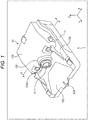
- Fig. 1 is a perspective view of an exemplary outward appearance of a front camera according to an embodiment of the present technology.
- the front camera 1 has a housing having a substantially flattened wedge shape sloping down forward in a side view.
- a normal direction along a Y-axis corresponds to a forward direction with respect to the front camera 1.
- the front camera 1 is formed by covering a bottom plate 11, forming a bottom face, and the like with a front case 12.
- the bottom plate 11 is formed by processing a thin plate member including metal such as aluminum and the front case 12 includes resin having high heat resistance.
- a housing portion 121 is formed to bulge while leaving narrow marginal portions on left and right sides (in an X-axis direction). Respective parts are housed in a space inside the housing portion 121. A forward portion of a top face of the housing portion 121 forms a slope gently sloping down forward.
- a semicylindrical arch portion 122 protruding forward is formed at a substantially central position of a front face side of the housing portion 121, and a substantially circular hole portion 122A is formed on a front face side of the arch portion 122.
- a lens module is provided in the housing portion 121 such that a lens 21 of the lens module is exposed from the hole portion 122A.
- a trapezoidal recessed portion 123 widening in the X-axis direction as it extends forward (in the normal direction along the Y-axis) and recessed shallowly to have a slope gently sloping down forward is formed on a forward side of the lens 21 provided to face the front.
- the recessed portion 123 is formed so as not to obstruct an angle of view of the front camera 1.
- a tip end protruding portion 124 forming a face continuous with the slope of the recessed portion 123 is formed.
- the tip end protruding portion 124 is a small chip member having a substantially trapezoidal shape with round corners in a plan view. Details of a shape of the front camera 1 will be described later.
- the front camera 1 having such a configuration in outward appearance is an onboard camera mounted to a vehicle such as an automobile.
- Fig. 2 is a view showing an example of a way to mount the front camera 1.
- Reference sign G designates a windshield of the car.
- a bracket 2 serving as a receiving-side mounting part to which the front camera 1 is mounted is mounted to an inner side (a side of a vehicle interior) of the windshield G.
- the bracket 2 is mounted, for example, near a rearview mirror.
- a left side of the windshield G is an outer side of the vehicle and a right side is an inner side of the vehicle.
- a band-shaped portion having a predetermined width is shown as a portion of the windshield in the example in Fig. 2 , the whole windshield G is actually formed by a broader glass member.
- the front camera 1 is mounted to the bracket 2 such that the lens 21 faces forward with respect to the vehicle, as shown as a colored portion in Fig. 3 .
- the front camera 1 is mounted in such a manner as to be able to take an image of an outside and forward view of the vehicle through the windshield G.
- the front camera 1 mounted to the bracket 2 is connected to a control unit mounted to the vehicle, for example, by wire.
- the front camera 1 has functions of analyzing the projected image captured during traveling of the vehicle and recognizing various kinds of objects including roads, pedestrians, obstacles, and the like.
- the front camera 1 has not only the image capturing function but also such an image analysis function.
- a Central Processing Unit (CPU) for executing a predetermined program to carry out the image analysis and the like, a memory, and the like are provided.
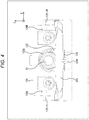
- Fig. 4 is a front view of the front camera 1.
- Fig. 5 is a left side view of the front camera 1 and
- Fig. 6 is a right side view of the front camera 1. Descriptions overlapping what have been described with reference to Fig. 1 will be omitted properly.
- a semicylindrical protruding portion 124A having a substantially U shape in a front view is formed on a bottom face side of the tip end protruding portion 124.
- a narrow groove is formed in a top face of the tip end protruding portion 124.
- a normal direction along the Z-axis is a direction in which the top face is oriented.
- a cylindrical protruding portion 125L is formed at a position of a left side face (a side face on a viewer's left hand side in the front view) of the housing portion 121 closer to a forward side.
- the protruding portion 125L is formed in a rear of a cylindrical protruding portion 125-1L by integrally forming a flattened laterally-long protruding portion 125-2L.
- the protruding portion 125-1L is slightly higher than the protruding portion 125-2L in the X-axis direction.
- a cylindrical protruding portion 125R is formed at a position of a right side face (a side face on a viewer's right hand side in the front view) of the housing portion 121 closer to the forward side.
- the protruding portion 125R is formed in a rea of a cylindrical protruding portion 125-1R by integrally forming a flattened laterally-long protruding portion 125-2R in a right side view.
- the protruding portion 125-1R is slightly higher than the protruding portion 125-2R in the X-axis direction.
- the front camera 1 is positionally aligned by inserting the tip end protruding portion 124 formed on a front face of the front camera 1 and the protruding portions 125L and 125R formed on the left and right opposite side faces into hole portions formed in corresponding positions of the bracket 2.
- a connecting portion 126L is formed between a front face of the housing portion 121 and the top face portion 12A.
- a substantially V-shaped notch portion 127L is formed in a forward part of the connecting portion 126L.
- a connecting portion 126R is formed between the front face of the housing portion 121 and the top face portion 12A.
- a substantially V-shaped notch portion 127R is formed in a forward part of the connecting portion 126R.
- the notch portion 127L and the notch portion 127R are also used in the mounting to the bracket 2.
- Fig. 7 is a back view of the front camera 1.
- a back face of the front camera 1 is formed by being covered with a back face portion 111 of the bottom plate 11.
- a laterally long rectangular hole portion 111A is formed substantially at a center of the back face portion 111 that is in a laterally long (long in the X-axis direction) bilaterally-symmetric victory stand shape, and a terminal 22 is formed in the hole portion 111A.
- a cable that connects the front camera 1 and the control unit is connected to the terminal 22.
- a plan configuration of the front camera 1 is shown in Fig. 8 and a bottom configuration of the front camera 1 is shown in Fig. 9 .
- the housing portion 121 is formed in an almost entire area behind a substantially central position of the front camera 1 while leaving narrow marginal portions on left and right sides.
- the protruding portion 125L and the protruding portion 125R are formed at substantially central positions in a front-rear direction (a Y-axis direction) of the front camera 1.
- the notch portion 127L is formed in a forward left end of the front camera 1 and the notch portion 127R is formed in a forward right end of the front camera 1.
- the bottom face of the front camera 1 is formed by being covered with a bottom face portion 112 of the bottom plate 11.
- the protruding portion 124A having a cylindrical face is formed on the bottom face side of the tip end protruding portion 124 provided at a center of the front face of the front camera 1.
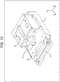
- Fig. 10 is a view of a state of the front camera 1 from which a front case 12 is detached.
- a main board 31, a top plate 32, and a shield plate 33 are provided in the front camera 1.
- the lens module is electrically connected to the main board 31.
- the top plate 32 is formed by processing, for example, a thin plate member including aluminum, similarly to the bottom plate 11.
- the shield plate 33 is formed by, for example, processing a thin plate member such as stainless steel.
- FIG. 11 A state where the main board 31, the top plate 32, and the shield plate 33 are detached is shown in Fig. 11 .
- the main board 31 is covered with the top plate 32 and the shield plate 33 from above and fixed to the bottom plate 11 by screwing the main board 31 together with the top plate 32.
- the shield plate 33 is screwed to the top plate 32.
- the top plate 32 is of such size and shape as to cover almost the entire main board 31.
- the shield plate 33 is put on the top plate 32 in such a manner as to close an opening in a bent portion formed at a position closer to a rear side of the top plate 32, and the shield plate 33 is screwed.
- the top plate 32 covers almost the entire main board 31.
- the opening in the top plate 32 is closed with the shield plate 33.
- Fig. 12 is an exploded view of the front camera 1. Main parts and an assembly method will be described.
- an LSI 51 is installed on the main board 31.
- An imager board 53 on which an image sensor is installed is mounted to the lens module 52.
- a flexible cable 54 is mounted to the imager board 53.
- the flexible cable 54 is a cable that connects the main board 31 and the imager board 53 on which the image sensor is installed.
- the lens module 52 is screwed to the top plate 32 by use of threaded holes A, A'. After the lens module 52 is mounted to the top plate 32, the flexible cable 54 is mounted to the main board 31.
- a holder 55 is a part for fixing the flexible cable 54.
- the holder 55 presses the flexible cable 54 mounted to connect the main board 31 and the imager board 53 from above to thereby fix the flexible cable 54.
- the hole portion in a top face of the top plate 32 is formed so that the holder 55 is put into the top plate 32.
- the shield plate 33 and the top plate 32 are secured with metal screws, and the top plate 32, the main board 31, and the bottom plate 11 are secured with metal screws.
- the top face of the top plate 32 is in contact with a back side of a top face of the shield plate 33 and it is possible to pass a current between the top plate 32 and the shield plate 33.
- the front case 12 is screwed to the top plate 32 and the lens module 52 by use of threaded holes B1, B1', B1", B2, B2', B2".
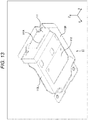
- Fig. 13 is an enlarged perspective view of the bottom plate 11.
- a left edge portion 113L and a right edge portion 113R that are laterally-long (in the Y-axis direction) band-shaped wall faces are respectively formed by bending a thin plate member vertically upward (in the normal direction along the Z-axis) with respect to a horizontal face of the bottom face portion 112. Tip ends of the left edge portion 113L and the right edge portion 113R are formed to be inclined forward.
- a forward side of the bottom face portion 112 is formed in a substantially prow shape in the side view by being curved to be a raised bottom.
- a back face portion 111 higher than the left edge portion 113L and the right edge portion 113R in the Z-axis direction is formed.
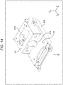
- Figs. 14 , 15 are enlarged perspective views of the top plate 32.
- a bent portion 321 is formed by bending a thin plate member.
- a substantially vertical face is formed on a front side of the bent portion 321 and a substantially horizontal face is formed on top of the bent portion 321.
- the bent portion 321 is open on a left side face side and a right side face side.
- a lens hole 321A in a substantially circular shape in a front view is formed substantially at a center of the vertical face formed on the front side of the bent portion 321 and the substantially trapezoidal mounting hole 321B is formed in the top face.
- the lens hole 321A is a hole portion through which the lens 21 of the lens module 52 is inserted from an inside of the bent portion 321.
- the mounting hole 321B is formed so that the holder 55 is put into the top plate 32 from above as described above.
- a left edge portion 323L and a right edge portion 323R that are laterally-long (in the Y-axis direction) band-shaped wall faces are respectively formed by bending a thin plate member vertically downward with respect to the top face portion 322 forming a horizontal face. Heights of the left edge portion 323L and the right edge portion 323R in the Z-axis direction are substantially the same as heights of the left edge portion 113L and the right edge portion 113R of the bottom plate 11 in the Z-axis direction.
- Fig. 16 is an enlarged perspective view of the shield plate 33. A state of the shield plate 33 seen from the front is shown in Fig. 17 .
- the shield plate 33 is formed by bending a thin plate member into a substantially bilaterally-symmetric victory stand shape in the front view.
- a left side face portion 332L forming a vertical face is formed on a left side face side of a top face portion 331 forming a horizontal face and a band-shaped portion 333L forming a narrow horizontal face is formed at a lower end of the left side face portion 332L.
- a bend portion 336L in a substantially V shape in the front view is formed.
- the bend portion 336L includes a vertical face 334L and a slope 335L.
- Six slits (notches) are formed at equal intervals in the vertical face 334L and the slope 335L.
- the vertically-long slits in vertically-inverted (in the Z-axis direction) U shapes are formed in the vertical face 334L and the slits slightly widening in the Y-axis direction as they extend upward are formed in the slope 335L.
- the bend portion 336L is formed in a substantially comb teeth shape. Due to the slits, the bend portion 336L has ductility (flexibility) against a force applied from the left.
- a right side face side of the shield plate 33 is formed similarly to the left side face side.
- a right side face portion 332R forming a vertical face is formed on a right side face side of the top face portion 331 and a band-shaped portion 333R forming a narrow horizontal face is formed at a lower end of the right side face portion 332R.
- a bend portion 336R in a substantially V shape in the front view is formed.
- the bend portion 336R includes a vertical face 334R and a slope 335R. Six slits are formed at equal intervals in the vertical face 334R and the slope 335R. The vertically long slits in vertically-inverted (in the Z-axis direction) U shapes are formed in the vertical face 334R and the slits slightly widening in the Y-axis direction as they extend upward are formed in the slope 335R.
- the bend portion 336R is also formed in a substantially comb teeth shape. Due to the slits, the bend portion 336R has ductility (flexibility) against a force applied from the right.
- the bottom plate 11, the top plate 32, and the shield plate 33 having such configurations are combined as described with reference to Figs. 10 , 11 .
- the left edge portion 323L and the right edge portion 323R of the top plate 32 are respectively positioned on inner sides of the left edge portion 113L and the right edge portion 113R of the bottom plate 11.
- Small clearances are respectively formed between the left edge portion 323L of the top plate 32 and the left edge portion 113L of the bottom plate 11 and between the right edge portion 323R of the top plate 32 and the right edge portion 113R of the bottom plate 11.
- the bent portion 321 of the top plate 32 is covered with the shield plate 33 from above.
- Fig. 18 is a view of a state where the bottom plate 11 is covered with the top plate 32 and the shield plate 33.
- the bottom plate 11 is transparent in Fig. 18 .
- the shield plate 33 is mounted to the top plate 32. If the top plate 32, the shield plate 33, and the bottom plate 11 are assembled, the bend portion 336L is inserted into the clearance between the left edge portion 323L of the top plate 32 and the left edge portion 113L of the bottom plate 11 and the bend portion 336R is inserted into the clearance between the right edge portion 323R of the top plate 32 and the right edge portion 113R of the bottom plate 11.
- the bend portion 336L and the bend portion 336R function as insertion portions that close the clearances between the top plate 32 and the bottom plate 11.
- the mounting hole 321B formed in the top face of the bent portion 321 is closed with the top face portion 331 of the shield plate 33. Furthermore, the openings on the left side face side and the right side face side of the bent portion 321 are respectively closed with the left side face portion 332L and the right side face portion 332R of the shield plate 33. Therefore, the electronic components on the main board 31 are shielded.
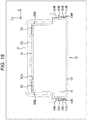
- Fig. 19 is a view showing a configuration of a section of the front camera 1 along line A-A ( Fig. 1 ). In Fig. 19 , details of the configuration appearing in the section are not shown.
- a width on an open side of the bend portion 336L (a distance between the vertical face 334L and a tip end of the slope 335L) before the assembly is slightly greater than a width of the clearance between the bottom plate 11 and the top plate 32.
- an upper end of the slope 335L of the bend portion 336L formed in the substantially V shape in the front view comes in contact with an inner side of the left edge portion 113L of the bottom plate 11. With this contact, it becomes possible to establish electrical conduction between the shield plate 33 and the bottom plate 11 via the bend portion 336L.
- a width on an open side of the bend portion 336R (a distance between the vertical face 334R and a tip end of the slope 335R) before the assembly is slightly greater than a width of the clearance between the bottom plate 11 and the top plate 32.
- an upper end of the slope 335R of the bend portion 336R formed in the substantially V shape in the front view comes in contact with an inner side of the right edge portion 113R of the bottom plate 11. With this contact, it becomes possible to establish electrical conduction between the shield plate 33 and the bottom plate 11 via the bend portion 336R.
- the slope 335L of the bend portion 336L comes in contact with the inner side of the left edge portion 113L of the bottom plate 11 and the slope 335R of the bend portion 336R comes in contact with the inner side of the right edge portion 113R of the bottom plate 11 to thereby close the clearances between the bottom plate 11 and the top plate 32.
- Fig. 20 is a view showing an example of a painted portion of the bottom plate 11.
- a hatched portion is the portion painted with a predetermined color such as black or a portion that can be painted. Normally, an outer side of the bottom plate 11 is painted. As can be seen from Fig. 20 , at least a portion of the inner side of the left edge portion 113L that comes in contact with the bend portion 336L is not painted and the metal thin plate member is exposed as it is. Although it is not shown in the figure, at least a portion of the inner side of the right edge portion 113R that comes in contact with the bend portion 336R is not painted either.
- Figs. 21 and 22 show an example of the way to close the clearances between the bottom plate 11 and the top plate 32.
- shield members such as narrow band-shaped gaskets 1001L, 1001R as shown in Figs. 21 and 22 is conceivable.
- the step of mounting the shield members becomes unnecessary, which facilitates the assembly.
- the bend portions 336L, 336R are formed in the substantially V shapes in the front view, it is possible to close the clearances between the bottom plate 11 and the top plate 32 with the bend portions 336L, 336R by only fitting the top plate 32 onto which the shield plate 33 is mounted into the bottom plate 11, which facilitates the assembly.
- bend portions 336L, 336R of the shield plate 33 are formed in the substantially V shapes in the front view, the bend portions 336L, 336R may be formed in substantially U shapes.
- widths of the bend portions 336L, 336R in a front-rear direction are substantially the same as a width of the shield plate 33 in the front-rear direction (the Y-axis direction)
- the bend portions 336L, 336R may be formed to extend forward. Widths of the bend portions 336L, 336R in the front-rear direction (the Y-axis direction) may be greater than the width of the shield plate 33 in the front-rear direction and the clearances between the bottom plate 11 and the top plate 32 may be closed in wider ranges.
- Substantially V-shaped or substantially U-shaped bend portions in the front view and having similar configurations to the bend portions 336L, 336R of the shield plate 33 may be provided to the left edge portion 323L, the right edge portion 323R of the top plate 32.
- the clearances between the bottom plate 11 and the top plate 32 are closed with the bend portions provided to the left and right opposite ends of the top plate 32.
- the shield structure for the onboard camera has been described, the above-described shield structure can be used as a structure for other electronic devices than the onboard camera.
- the present technology may have the following configurations.
Landscapes
- Engineering & Computer Science (AREA)
- Multimedia (AREA)
- Signal Processing (AREA)
- Physics & Mathematics (AREA)
- General Physics & Mathematics (AREA)
- Electromagnetism (AREA)
- Microelectronics & Electronic Packaging (AREA)
- Studio Devices (AREA)
- Camera Bodies And Camera Details Or Accessories (AREA)
- Shielding Devices Or Components To Electric Or Magnetic Fields (AREA)
Abstract
Description
- The present technology relates to an onboard camera and particularly to an onboard camera that enables a camera chassis to be easily assembled while providing shielding between plates.
- In recent years, there are more and more automobiles in which a camera is mounted. For example, images captured by the camera are used to detect objects such as white lines on roads, traffic lights, road signs, oncoming cars, and pedestrians and to provide traveling assistance and visibility assistance on the basis of detection results.
- From viewpoints of heat resistance, impact resistance, and the like, a chassis of the onboard camera has a box structure formed by combining a plurality of metal plates. In order to establish conduction between the metal plates and to secure electromagnetic wave shielding performance, "a shield finger" or "a gasket" is used as a shield member between the metal plates in some cases.
- Patent Document 1: Japanese Patent Application Laid-Open No.
2018-022953 - In a case where the above-described "shield finger" or "gasket" is used between the metal plates, the number of parts increases naturally.
- Furthermore, such shield members are mounted by use of adhesive tape and it is impossible to secure conductivity as expected depending on a quality of material of the adhesive tape.
- Furthermore, in a case where the adhesive tape is used for mounting of the shield member, the shield member may be positionally displaced or detached during assembly or after the assembly in some cases.
- The present technology has been made with such circumstances in view and enables a camera chassis to be easily assembled while providing shielding between plates.
- An onboard camera according to an aspect of the present technology has an internal structure including: a bottom face plate which forms a bottom face of a housing and has end portions serving as wall faces formed respectively at opposite ends of the bottom face plate; a board on which an electronic component is installed; a top face plate which covers the board and has end portions serving as wall faces formed respectively at opposite ends of the top face plate; and a shield plate which has insertion portions formed at opposite ends, the insertion portions being positioned in clearances between the end portions of the bottom face plate and the end portions of the top face plate to close the clearances.
- According to the aspect of the present technology, the insertion portions of the shield plate are positioned in the clearances between the end portions of the bottom face plate and the end portions of the top face plate to thereby close the clearances.
- With the present technology, it is possible to easily assemble a camera chassis while providing shielding between the plates.
- Note that the effect described herein is not necessarily a sole effect and any of effects described herein may be exerted.
-
-
Fig. 1 is a perspective view of an exemplary outward appearance of a front camera according to an embodiment of the present technology. -
Fig. 2 is a view showing an example of a way to mount the front camera. -
Fig. 3 is a view of a state where the front camera is mounted to a bracket. -
Fig. 4 is a front view of the front camera. -
Fig. 5 is a left side view of the front camera. -
Fig. 6 is a right side view of the front camera. -
Fig. 7 is a back view of the front camera. -
Fig. 8 is a plan view of the front camera. -
Fig. 9 is a bottom view of the front camera. -
Fig. 10 is a view of a state where a front case is detached. -
Fig. 11 is a view of a state where a main board, a top plate, and a shield plate are detached. -
Fig. 12 is an exploded view of the front camera. -
Fig. 13 is an enlarged perspective view of a bottom plate. -
Fig. 14 is an enlarged perspective view of the top plate. -
Fig. 15 is another enlarged perspective view of the top plate. -
Fig. 16 is an enlarged perspective view of the shield plate. -
Fig. 17 is an enlarged front view of the shield plate. -
Fig. 18 is a view of a state where the shield plate is put on. -
Fig. 19 is a view showing a configuration of a section of the front camera. -
Fig. 20 is a view showing an example of a painted portion of the bottom plate. -
Fig. 21 is a view showing an example of a way to close clearances. -
Fig. 22 is a view showing the example of the way to close the clearances. - A mode for carrying out the present technology will be described below. The description will be given in the following order.
- 1. Outward appearance of front camera
- 2. Configurations of respective faces of front camera
- 3. Internal structure of front camera
- 4. Configurations of respective plates
- 5. Internal configuration
- 6. Modifications
-
Fig. 1 is a perspective view of an exemplary outward appearance of a front camera according to an embodiment of the present technology. - The front camera 1 has a housing having a substantially flattened wedge shape sloping down forward in a side view. In
Fig. 1 , a normal direction along a Y-axis corresponds to a forward direction with respect to the front camera 1. - The front camera 1 is formed by covering a
bottom plate 11, forming a bottom face, and the like with afront case 12. For example, thebottom plate 11 is formed by processing a thin plate member including metal such as aluminum and thefront case 12 includes resin having high heat resistance. - In a rear of a
top face portion 12A of thefront case 12, ahousing portion 121 is formed to bulge while leaving narrow marginal portions on left and right sides (in an X-axis direction). Respective parts are housed in a space inside thehousing portion 121. A forward portion of a top face of thehousing portion 121 forms a slope gently sloping down forward. - A semicylindrical
arch portion 122 protruding forward is formed at a substantially central position of a front face side of thehousing portion 121, and a substantiallycircular hole portion 122A is formed on a front face side of thearch portion 122. A lens module is provided in thehousing portion 121 such that alens 21 of the lens module is exposed from thehole portion 122A. - A trapezoidal recessed
portion 123 widening in the X-axis direction as it extends forward (in the normal direction along the Y-axis) and recessed shallowly to have a slope gently sloping down forward is formed on a forward side of thelens 21 provided to face the front. The recessedportion 123 is formed so as not to obstruct an angle of view of the front camera 1. - At a center of a tip end of the front camera 1, a tip
end protruding portion 124 forming a face continuous with the slope of the recessedportion 123 is formed. The tipend protruding portion 124 is a small chip member having a substantially trapezoidal shape with round corners in a plan view. Details of a shape of the front camera 1 will be described later. - The front camera 1 having such a configuration in outward appearance is an onboard camera mounted to a vehicle such as an automobile.
-
Fig. 2 is a view showing an example of a way to mount the front camera 1. Reference sign G designates a windshield of the car. - As shown in
Fig. 2 , abracket 2 serving as a receiving-side mounting part to which the front camera 1 is mounted is mounted to an inner side (a side of a vehicle interior) of the windshield G. Thebracket 2 is mounted, for example, near a rearview mirror. - In
Fig. 2 , a left side of the windshield G is an outer side of the vehicle and a right side is an inner side of the vehicle. Although only a band-shaped portion having a predetermined width is shown as a portion of the windshield in the example inFig. 2 , the whole windshield G is actually formed by a broader glass member. - The front camera 1 is mounted to the
bracket 2 such that thelens 21 faces forward with respect to the vehicle, as shown as a colored portion inFig. 3 . In other words, the front camera 1 is mounted in such a manner as to be able to take an image of an outside and forward view of the vehicle through the windshield G. The front camera 1 mounted to thebracket 2 is connected to a control unit mounted to the vehicle, for example, by wire. - The front camera 1 has functions of analyzing the projected image captured during traveling of the vehicle and recognizing various kinds of objects including roads, pedestrians, obstacles, and the like. The front camera 1 has not only the image capturing function but also such an image analysis function. In the front camera 1, a Central Processing Unit (CPU) for executing a predetermined program to carry out the image analysis and the like, a memory, and the like are provided.
- On the basis of a result of the recognition by the front camera 1, various kinds of processing such as traveling control and provision of information to a driver are performed by the control unit mounted to the vehicle.
- Configurations of respective faces of the front camera 1 will be described.
-
Fig. 4 is a front view of the front camera 1.Fig. 5 is a left side view of the front camera 1 andFig. 6 is a right side view of the front camera 1. Descriptions overlapping what have been described with reference toFig. 1 will be omitted properly. - As shown in
Fig. 4 , asemicylindrical protruding portion 124A having a substantially U shape in a front view is formed on a bottom face side of the tipend protruding portion 124. A narrow groove is formed in a top face of the tipend protruding portion 124. InFig. 4 , a normal direction along the Z-axis is a direction in which the top face is oriented. - At a position of a left side face (a side face on a viewer's left hand side in the front view) of the
housing portion 121 closer to a forward side, a cylindrical protrudingportion 125L is formed. As shown inFig. 5 , the protrudingportion 125L is formed in a rear of a cylindrical protruding portion 125-1L by integrally forming a flattened laterally-long protruding portion 125-2L. The protruding portion 125-1L is slightly higher than the protruding portion 125-2L in the X-axis direction. - On the other hand, at a position of a right side face (a side face on a viewer's right hand side in the front view) of the
housing portion 121 closer to the forward side, a cylindrical protrudingportion 125R is formed. As shown inFig. 6 , the protrudingportion 125R is formed in a rea of a cylindrical protruding portion 125-1R by integrally forming a flattened laterally-long protruding portion 125-2R in a right side view. The protruding portion 125-1R is slightly higher than the protruding portion 125-2R in the X-axis direction. - The front camera 1 is positionally aligned by inserting the tip
end protruding portion 124 formed on a front face of the front camera 1 and the protrudingportions bracket 2. - As shown in
Fig. 5 , on a front face side of thehousing portion 121, a connectingportion 126L is formed between a front face of thehousing portion 121 and thetop face portion 12A. In a forward part of the connectingportion 126L, a substantially V-shapednotch portion 127L is formed. - On the other hand, as shown in
Fig. 6 , on the front face side of thehousing portion 121, a connectingportion 126R is formed between the front face of thehousing portion 121 and thetop face portion 12A. In a forward part of the connectingportion 126R, a substantially V-shapednotch portion 127R is formed. - The
notch portion 127L and thenotch portion 127R are also used in the mounting to thebracket 2. -
Fig. 7 is a back view of the front camera 1. - A back face of the front camera 1 is formed by being covered with a
back face portion 111 of thebottom plate 11. A laterally longrectangular hole portion 111A is formed substantially at a center of theback face portion 111 that is in a laterally long (long in the X-axis direction) bilaterally-symmetric victory stand shape, and a terminal 22 is formed in thehole portion 111A. A cable that connects the front camera 1 and the control unit is connected to the terminal 22. - A plan configuration of the front camera 1 is shown in
Fig. 8 and a bottom configuration of the front camera 1 is shown inFig. 9 . - As shown in
Fig. 8 , thehousing portion 121 is formed in an almost entire area behind a substantially central position of the front camera 1 while leaving narrow marginal portions on left and right sides. - Furthermore, the protruding
portion 125L and the protrudingportion 125R are formed at substantially central positions in a front-rear direction (a Y-axis direction) of the front camera 1. Thenotch portion 127L is formed in a forward left end of the front camera 1 and thenotch portion 127R is formed in a forward right end of the front camera 1. - As shown in
Fig. 9 , the bottom face of the front camera 1 is formed by being covered with abottom face portion 112 of thebottom plate 11. The protrudingportion 124A having a cylindrical face is formed on the bottom face side of the tipend protruding portion 124 provided at a center of the front face of the front camera 1. -
Fig. 10 is a view of a state of the front camera 1 from which afront case 12 is detached. - As shown in
Fig. 10 , amain board 31, atop plate 32, and ashield plate 33 are provided in the front camera 1. - On the
main board 31, various kinds of electronic components such as a CPU and a memory are provided. The lens module is electrically connected to themain board 31. Thetop plate 32 is formed by processing, for example, a thin plate member including aluminum, similarly to thebottom plate 11. Theshield plate 33 is formed by, for example, processing a thin plate member such as stainless steel. - A state where the
main board 31, thetop plate 32, and theshield plate 33 are detached is shown inFig. 11 . - As shown in
Fig. 11 , themain board 31 is covered with thetop plate 32 and theshield plate 33 from above and fixed to thebottom plate 11 by screwing themain board 31 together with thetop plate 32. Theshield plate 33 is screwed to thetop plate 32. Thetop plate 32 is of such size and shape as to cover almost the entiremain board 31. - The
shield plate 33 is put on thetop plate 32 in such a manner as to close an opening in a bent portion formed at a position closer to a rear side of thetop plate 32, and theshield plate 33 is screwed. Thetop plate 32 covers almost the entiremain board 31. The opening in thetop plate 32 is closed with theshield plate 33. With thetop plate 32, theshield plate 33, and thebottom plate 11, the electronic components on themain board 31 can be shielded from surroundings. -
Fig. 12 is an exploded view of the front camera 1. Main parts and an assembly method will be described. - As shown in
Fig. 12 , anLSI 51 is installed on themain board 31. Animager board 53 on which an image sensor is installed is mounted to thelens module 52. Moreover, aflexible cable 54 is mounted to theimager board 53. Theflexible cable 54 is a cable that connects themain board 31 and theimager board 53 on which the image sensor is installed. - The
lens module 52 is screwed to thetop plate 32 by use of threaded holes A, A'. After thelens module 52 is mounted to thetop plate 32, theflexible cable 54 is mounted to themain board 31. - A
holder 55 is a part for fixing theflexible cable 54. Theholder 55 presses theflexible cable 54 mounted to connect themain board 31 and theimager board 53 from above to thereby fix theflexible cable 54. The hole portion in a top face of thetop plate 32 is formed so that theholder 55 is put into thetop plate 32. - Thereafter, the
shield plate 33 and thetop plate 32 are secured with metal screws, and thetop plate 32, themain board 31, and thebottom plate 11 are secured with metal screws. Note that the top face of thetop plate 32 is in contact with a back side of a top face of theshield plate 33 and it is possible to pass a current between thetop plate 32 and theshield plate 33. - Thereafter, the
front case 12 is screwed to thetop plate 32 and thelens module 52 by use of threaded holes B1, B1', B1", B2, B2', B2". - Here, details of the
bottom plate 11, thetop plate 32, and theshield plate 33 forming a shield structure of the front camera 1 will be described. -
Fig. 13 is an enlarged perspective view of thebottom plate 11. - As shown in
Fig. 13 , at a left end and a right end of thebottom plate 11, aleft edge portion 113L and aright edge portion 113R that are laterally-long (in the Y-axis direction) band-shaped wall faces are respectively formed by bending a thin plate member vertically upward (in the normal direction along the Z-axis) with respect to a horizontal face of thebottom face portion 112. Tip ends of theleft edge portion 113L and theright edge portion 113R are formed to be inclined forward. - A forward side of the
bottom face portion 112 is formed in a substantially prow shape in the side view by being curved to be a raised bottom. On a back face side of thebottom face portion 112, aback face portion 111 higher than theleft edge portion 113L and theright edge portion 113R in the Z-axis direction is formed. -
Figs. 14 ,15 are enlarged perspective views of thetop plate 32. - As shown in
Figs. 14 ,15 , at a portion of thetop plate 32 closer to a rear side, abent portion 321 is formed by bending a thin plate member. A substantially vertical face is formed on a front side of thebent portion 321 and a substantially horizontal face is formed on top of thebent portion 321. Thebent portion 321 is open on a left side face side and a right side face side. - A
lens hole 321A in a substantially circular shape in a front view is formed substantially at a center of the vertical face formed on the front side of thebent portion 321 and the substantially trapezoidal mountinghole 321B is formed in the top face. Thelens hole 321A is a hole portion through which thelens 21 of thelens module 52 is inserted from an inside of thebent portion 321. The mountinghole 321B is formed so that theholder 55 is put into thetop plate 32 from above as described above. - At a left end and a right end of the
top plate 32, aleft edge portion 323L and aright edge portion 323R that are laterally-long (in the Y-axis direction) band-shaped wall faces are respectively formed by bending a thin plate member vertically downward with respect to thetop face portion 322 forming a horizontal face. Heights of theleft edge portion 323L and theright edge portion 323R in the Z-axis direction are substantially the same as heights of theleft edge portion 113L and theright edge portion 113R of thebottom plate 11 in the Z-axis direction. -
Fig. 16 is an enlarged perspective view of theshield plate 33. A state of theshield plate 33 seen from the front is shown inFig. 17 . - As shown in
Fig. 17 , theshield plate 33 is formed by bending a thin plate member into a substantially bilaterally-symmetric victory stand shape in the front view. - In other words, a left
side face portion 332L forming a vertical face is formed on a left side face side of atop face portion 331 forming a horizontal face and a band-shapedportion 333L forming a narrow horizontal face is formed at a lower end of the leftside face portion 332L. At a left end of the band-shapedportion 333L, abend portion 336L in a substantially V shape in the front view is formed. - The
bend portion 336L includes avertical face 334L and aslope 335L. Six slits (notches) are formed at equal intervals in thevertical face 334L and theslope 335L. The vertically-long slits in vertically-inverted (in the Z-axis direction) U shapes are formed in thevertical face 334L and the slits slightly widening in the Y-axis direction as they extend upward are formed in theslope 335L. - As the slits are formed, the
bend portion 336L is formed in a substantially comb teeth shape. Due to the slits, thebend portion 336L has ductility (flexibility) against a force applied from the left. - A right side face side of the
shield plate 33 is formed similarly to the left side face side. In other words, a rightside face portion 332R forming a vertical face is formed on a right side face side of thetop face portion 331 and a band-shapedportion 333R forming a narrow horizontal face is formed at a lower end of the rightside face portion 332R. At a right end of the band-shapedportion 333R, abend portion 336R in a substantially V shape in the front view is formed. - The
bend portion 336R includes avertical face 334R and aslope 335R. Six slits are formed at equal intervals in thevertical face 334R and theslope 335R. The vertically long slits in vertically-inverted (in the Z-axis direction) U shapes are formed in thevertical face 334R and the slits slightly widening in the Y-axis direction as they extend upward are formed in theslope 335R. - As the slits are formed, the
bend portion 336R is also formed in a substantially comb teeth shape. Due to the slits, thebend portion 336R has ductility (flexibility) against a force applied from the right. - The
bottom plate 11, thetop plate 32, and theshield plate 33 having such configurations are combined as described with reference toFigs. 10 ,11 . - When the
top plate 32 is put on, theleft edge portion 323L and theright edge portion 323R of thetop plate 32 are respectively positioned on inner sides of theleft edge portion 113L and theright edge portion 113R of thebottom plate 11. Small clearances are respectively formed between theleft edge portion 323L of thetop plate 32 and theleft edge portion 113L of thebottom plate 11 and between theright edge portion 323R of thetop plate 32 and theright edge portion 113R of thebottom plate 11. - The
bent portion 321 of thetop plate 32 is covered with theshield plate 33 from above. -
Fig. 18 is a view of a state where thebottom plate 11 is covered with thetop plate 32 and theshield plate 33. For the sake of convenience of explanation, thebottom plate 11 is transparent inFig. 18 . - The
shield plate 33 is mounted to thetop plate 32. If thetop plate 32, theshield plate 33, and thebottom plate 11 are assembled, thebend portion 336L is inserted into the clearance between theleft edge portion 323L of thetop plate 32 and theleft edge portion 113L of thebottom plate 11 and thebend portion 336R is inserted into the clearance between theright edge portion 323R of thetop plate 32 and theright edge portion 113R of thebottom plate 11. Thebend portion 336L and thebend portion 336R function as insertion portions that close the clearances between thetop plate 32 and thebottom plate 11. - When the
shield plate 33 is put on thetop plate 32, the mountinghole 321B formed in the top face of thebent portion 321 is closed with thetop face portion 331 of theshield plate 33. Furthermore, the openings on the left side face side and the right side face side of thebent portion 321 are respectively closed with the leftside face portion 332L and the rightside face portion 332R of theshield plate 33. Therefore, the electronic components on themain board 31 are shielded. -
Fig. 19 is a view showing a configuration of a section of the front camera 1 along line A-A (Fig. 1 ). InFig. 19 , details of the configuration appearing in the section are not shown. - A width on an open side of the
bend portion 336L (a distance between thevertical face 334L and a tip end of theslope 335L) before the assembly is slightly greater than a width of the clearance between thebottom plate 11 and thetop plate 32. As shown in a lower left portion ofFig. 19 , an upper end of theslope 335L of thebend portion 336L formed in the substantially V shape in the front view comes in contact with an inner side of theleft edge portion 113L of thebottom plate 11. With this contact, it becomes possible to establish electrical conduction between theshield plate 33 and thebottom plate 11 via thebend portion 336L. - Furthermore, a width on an open side of the
bend portion 336R (a distance between thevertical face 334R and a tip end of theslope 335R) before the assembly is slightly greater than a width of the clearance between thebottom plate 11 and thetop plate 32. As shown in a lower right portion ofFig. 19 , an upper end of theslope 335R of thebend portion 336R formed in the substantially V shape in the front view comes in contact with an inner side of theright edge portion 113R of thebottom plate 11. With this contact, it becomes possible to establish electrical conduction between theshield plate 33 and thebottom plate 11 via thebend portion 336R. - The
slope 335L of thebend portion 336L comes in contact with the inner side of theleft edge portion 113L of thebottom plate 11 and theslope 335R of thebend portion 336R comes in contact with the inner side of theright edge portion 113R of thebottom plate 11 to thereby close the clearances between thebottom plate 11 and thetop plate 32. - Because it becomes possible to establish the electrical conduction between the
shield plate 33 and thebottom plate 11 via thebend portion 336R/336L, it becomes possible to establish the electrical conduction between theshield plate 33, thetop plate 32, and thebottom plate 11. Therefore, it is possible to shield electromagnetic wave radiated by the electronic components on themain board 31 and it is possible to prevent influences of disturbance noise. -
Fig. 20 is a view showing an example of a painted portion of thebottom plate 11. - In
Fig. 20 , a hatched portion is the portion painted with a predetermined color such as black or a portion that can be painted. Normally, an outer side of thebottom plate 11 is painted. As can be seen fromFig. 20 , at least a portion of the inner side of theleft edge portion 113L that comes in contact with thebend portion 336L is not painted and the metal thin plate member is exposed as it is. Although it is not shown in the figure, at least a portion of the inner side of theright edge portion 113R that comes in contact with thebend portion 336R is not painted either. - By not painting the inner sides (the portions with which the
bend portion 336L, thebend portion 336R come in contact) of theleft edge portion 113L and theright edge portion 113R, it is possible to more reliably secure the electric conduction between thebottom plate 11 and theshield plate 33. Besides this configuration, in a case where another portion for securing conduction between thebottom plate 11 and themain board 31 or thetop plate 32 is provided on an inner side of thebottom plate 11, the portion may not be painted and the metal thin plate material may be exposed as it is. -
Figs. 21 and22 show an example of the way to close the clearances between thebottom plate 11 and thetop plate 32. - As another method of closing the clearance between the
bottom plate 11 and thetop plate 32 without using thebend portions shield plate 33, a method using shield members such as narrow band-shapedgaskets Figs. 21 and22 is conceivable. - In this case, it is necessary to prepare the shield members. Furthermore, in assembly, it is necessary to carry out the assembly after sticking the shield members to the
top plate 32 or thebottom plate 11. - By forming the
bend portions shield plate 33 and closing the clearances between thebottom plate 11 and thetop plate 32 with thebend portions - Furthermore, the step of mounting the shield members becomes unnecessary, which facilitates the assembly. Moreover, because the
bend portions bottom plate 11 and thetop plate 32 with thebend portions top plate 32 onto which theshield plate 33 is mounted into thebottom plate 11, which facilitates the assembly. - Although the
bend portions shield plate 33 are formed in the substantially V shapes in the front view, thebend portions - Furthermore, although widths of the
bend portions shield plate 33 in the front-rear direction (the Y-axis direction), thebend portions bend portions shield plate 33 in the front-rear direction and the clearances between thebottom plate 11 and thetop plate 32 may be closed in wider ranges. - Thus, it is possible to more reliably close the clearances between the
bottom plate 11 and thetop plate 32. - Substantially V-shaped or substantially U-shaped bend portions in the front view and having similar configurations to the
bend portions shield plate 33 may be provided to theleft edge portion 323L, theright edge portion 323R of thetop plate 32. In this case, the clearances between thebottom plate 11 and thetop plate 32 are closed with the bend portions provided to the left and right opposite ends of thetop plate 32. - Although the shield structure for the onboard camera has been described, the above-described shield structure can be used as a structure for other electronic devices than the onboard camera.
- Note that effects described herein are merely examples and not sole effects and other effects may be exerted.
- The present technology may have the following configurations.
- (1)
An onboard camera having an internal structure including:- a bottom face plate which forms a bottom face of a housing and has end portions serving as wall faces formed respectively at opposite ends of the bottom face plate;
- a board on which an electronic component is installed;
- a top face plate which covers the board and has end portions serving as wall faces formed respectively at opposite ends of the top face plate; and
- a shield plate which has insertion portions formed at opposite ends, the insertion portions being positioned in clearances between the end portions of the bottom face plate and the end portions of the top face plate to close the clearances.
- (2)
The onboard camera according to the item (1),
in which the bottom face plate, the top face plate, and the shield plate respectively include metal plate members. - (3)
The onboard camera according to the item (2),
in which the shield plate has such a shape as to close a hole portion formed in a predetermined face of the top face plate. - (4)
The onboard camera according to the item (2) or (3), in which the insertion portions are formed by bending the metal plate member into V shapes or U shapes. - (5)
The onboard camera according to the item (4),
in which a width of an open side of each of the insertion portions before assembly is greater than a width of each of the clearances. - (6)
The onboard camera according to the item (4) or (5), in which a slit is formed in each of the insertion portions. - (7)
The onboard camera according to any one of the items (1) to (6),
in which at least a portion of the bottom face plate with which the insertion portions come in contact is not painted. - (8)
The onboard camera according to any one of the items (1) to (7),
in which the end portions at the left and right opposite ends of the bottom face plate are respectively formed by bending the metal plate member upward and
the end portions at the left and right opposite ends of the top face plate are respectively formed by bending the metal plate member downward. -
- 1
- Front camera
- 11
- Bottom plate
- 12
- Front case
- 31
- Main board
- 32
- Top plate
- 33
- Shield plate
Claims (8)
- An onboard camera comprising an internal structure including:a bottom face plate which forms a bottom face of a housing and has end portions serving as wall faces formed respectively at opposite ends of the bottom face plate;a board on which an electronic component is installed;a top face plate which covers the board and has end portions serving as wall faces formed respectively at opposite ends of the top face plate; anda shield plate which has insertion portions formed at opposite ends, the insertion portions being positioned in clearances between the end portions of the bottom face plate and the end portions of the top face plate to close the clearances.
- The onboard camera according to claim 1,
wherein the bottom face plate, the top face plate, and the shield plate respectively include metal plate members. - The onboard camera according to claim 2,
wherein the shield plate has such a shape as to close a hole portion formed in a predetermined face of the top face plate. - The onboard camera according to claim 2,
wherein the insertion portions are formed by bending the metal plate member into V shapes or U shapes. - The onboard camera according to claim 4,
wherein a width of an open side of each of the insertion portions before assembly is greater than a width of each of the clearances. - The onboard camera according to claim 4,
wherein a slit is formed in each of the insertion portions. - The onboard camera according to claim 1,
wherein at least a portion of the bottom face plate with which the insertion portions come in contact is not painted. - The onboard camera according to claim 1,
wherein the end portions at the left and right opposite ends of the bottom face plate are respectively formed by bending a metal plate member upward and
the end portions at the left and right opposite ends of the top face plate are respectively formed by bending a metal plate member downward.
Applications Claiming Priority (2)
| Application Number | Priority Date | Filing Date | Title |
|---|---|---|---|
| JP2018143617 | 2018-07-31 | ||
| PCT/JP2019/028011 WO2020026800A1 (en) | 2018-07-31 | 2019-07-17 | Vehicle-mounted camera |
Publications (3)
| Publication Number | Publication Date |
|---|---|
| EP3832998A1 true EP3832998A1 (en) | 2021-06-09 |
| EP3832998A4 EP3832998A4 (en) | 2021-08-25 |
| EP3832998B1 EP3832998B1 (en) | 2025-11-12 |
Family
ID=69231035
Family Applications (1)
| Application Number | Title | Priority Date | Filing Date |
|---|---|---|---|
| EP19844820.1A Active EP3832998B1 (en) | 2018-07-31 | 2019-07-17 | Vehicle-mounted camera |
Country Status (6)
| Country | Link |
|---|---|
| US (1) | US11831971B2 (en) |
| EP (1) | EP3832998B1 (en) |
| JP (1) | JP7322027B2 (en) |
| KR (1) | KR102780258B1 (en) |
| CN (1) | CN112470457B (en) |
| WO (1) | WO2020026800A1 (en) |
Families Citing this family (7)
| Publication number | Priority date | Publication date | Assignee | Title |
|---|---|---|---|---|
| EP3831660B1 (en) | 2018-07-31 | 2022-08-31 | Sony Semiconductor Solutions Corporation | Onboard camera holding method, onboard camera, bracket |
| JP7407017B2 (en) * | 2020-02-28 | 2023-12-28 | 株式会社東海理化電機製作所 | Installation equipment |
| JP7645736B2 (en) * | 2021-07-21 | 2025-03-14 | ニデックプレシジョン株式会社 | Blade drive device |
| DE102021129929A1 (en) * | 2021-11-17 | 2023-05-17 | Valeo Schalter Und Sensoren Gmbh | Vehicle camera, housing for at least one vehicle camera and vehicle with at least one vehicle camera |
| DE102021133449A1 (en) * | 2021-12-16 | 2023-06-22 | Valeo Schalter Und Sensoren Gmbh | First housing part for a housing for a device for a vehicle, housing, device, vehicle with at least one device and method for assembling a device |
| JP2025018344A (en) * | 2023-07-26 | 2025-02-06 | パナソニックオートモーティブシステムズ株式会社 | On-vehicle camera |
| US20250042343A1 (en) * | 2023-07-31 | 2025-02-06 | ZF Passive Safety Systems US Inc. | Mounting arrangement for a vehicle sensor |
Family Cites Families (34)
| Publication number | Priority date | Publication date | Assignee | Title |
|---|---|---|---|---|
| JPH0897584A (en) * | 1994-09-28 | 1996-04-12 | Matsushita Electric Ind Co Ltd | High frequency equipment and low noise block converter |
| US6294729B1 (en) | 1997-10-31 | 2001-09-25 | Laird Technologies | Clad polymer EMI shield |
| KR100674833B1 (en) | 2005-02-16 | 2007-01-26 | 삼성전기주식회사 | Camera module |
| CN2916996Y (en) * | 2006-07-11 | 2007-06-27 | 富士康(昆山)电脑接插件有限公司 | electrical connector |
| KR101327622B1 (en) * | 2007-03-30 | 2013-11-12 | 엘지이노텍 주식회사 | Camera module |
| US7722398B2 (en) * | 2007-04-13 | 2010-05-25 | Hon Hai Precision Ind. Co., Ltd. | Electrical connector assembly with a protecting section over a flexible printed circuit board connected thereto |
| JP5239332B2 (en) * | 2007-12-27 | 2013-07-17 | アイシン精機株式会社 | Vehicle seat slide device |
| US8482664B2 (en) * | 2008-10-16 | 2013-07-09 | Magna Electronics Inc. | Compact camera and cable system for vehicular applications |
| JP5494927B2 (en) * | 2009-08-03 | 2014-05-21 | 株式会社リコー | Camera unit and sensing device |
| JP5609779B2 (en) * | 2011-06-13 | 2014-10-22 | 株式会社デンソー | Electronic control unit |
| JP2014011565A (en) | 2012-06-28 | 2014-01-20 | Kyocera Corp | Camera module |
| DE102013005801B4 (en) | 2013-04-04 | 2015-06-25 | Daimler Ag | Support device for attachment to a window of a motor vehicle and motor vehicles |
| JP2015193366A (en) | 2014-03-17 | 2015-11-05 | 日本電産エレシス株式会社 | Manufacturing method of box body for on-vehicle camera, box body for on-vehicle camera, and on-vehicle camera |
| JP2015216444A (en) | 2014-05-08 | 2015-12-03 | Smk株式会社 | Imaging device |
| US9896039B2 (en) * | 2014-05-09 | 2018-02-20 | Magna Electronics Inc. | Vehicle vision system with forward viewing camera |
| US20160009439A1 (en) | 2014-07-14 | 2016-01-14 | Rock-Tenn Shared Services, Llc | Tab style container with internal support structures |
| DE102014012001B4 (en) | 2014-08-12 | 2021-07-22 | Daimler Ag | Carrier device for fastening to a window of a motor vehicle and motor vehicle |
| KR101886204B1 (en) * | 2014-12-31 | 2018-08-08 | 젠텍스 코포레이션 | Rear vehicle camera |
| JP6197812B2 (en) | 2015-03-05 | 2017-09-20 | トヨタ自動車株式会社 | In-vehicle camera mounting structure |
| KR20160136710A (en) * | 2015-05-20 | 2016-11-30 | 삼성전기주식회사 | Camera Module |
| WO2017046972A1 (en) | 2015-09-14 | 2017-03-23 | 株式会社ヨコオ | Onboard antenna device |
| KR102502284B1 (en) * | 2016-01-12 | 2023-02-22 | 엘지이노텍 주식회사 | Camera module |
| US10232798B2 (en) | 2016-01-29 | 2019-03-19 | Veoneer Us, Inc. | Apparatuses for mounting camera arrangements on motor vehicles |
| JP6510999B2 (en) | 2016-03-24 | 2019-05-08 | 本田技研工業株式会社 | Sensor bracket |
| JP6565806B2 (en) | 2016-06-28 | 2019-08-28 | 株式会社デンソー | Camera system |
| JP2018022953A (en) | 2016-08-01 | 2018-02-08 | ソニーセミコンダクタソリューションズ株式会社 | In-vehicle camera, in-vehicle camera device, and in-vehicle camera support method |
| WO2018047491A1 (en) * | 2016-09-06 | 2018-03-15 | ソニーセミコンダクタソリューションズ株式会社 | Electronic device, camera apparatus, and shield chassis |
| EP3518033B1 (en) | 2016-09-21 | 2021-04-14 | Hitachi Automotive Systems, Ltd. | Imaging device |
| CN109982895B (en) * | 2016-11-18 | 2022-06-24 | 本田技研工业株式会社 | Vehicle-mounted electronic device mounting structure |
| KR102639380B1 (en) | 2016-11-29 | 2024-02-21 | 미쓰미덴기가부시기가이샤 | Lens drive device, camera module, and camera mounting device |
| US10288986B2 (en) | 2017-02-22 | 2019-05-14 | Trw Automotive U.S. Llc | Moderation of a driver assist camera enhancement via a vehicle windshield |
| EP3410687B1 (en) * | 2017-05-30 | 2019-12-25 | Veoneer Sweden AB | Camera module for a motor vehicle, method of using, and method of assembling a camera module |
| JP6508603B2 (en) * | 2017-06-20 | 2019-05-08 | 本田技研工業株式会社 | Sensor bracket |
| EP3831660B1 (en) | 2018-07-31 | 2022-08-31 | Sony Semiconductor Solutions Corporation | Onboard camera holding method, onboard camera, bracket |
-
2019
- 2019-07-17 JP JP2020533405A patent/JP7322027B2/en active Active
- 2019-07-17 KR KR1020217001364A patent/KR102780258B1/en active Active
- 2019-07-17 US US17/262,158 patent/US11831971B2/en active Active
- 2019-07-17 CN CN201980049154.0A patent/CN112470457B/en active Active
- 2019-07-17 EP EP19844820.1A patent/EP3832998B1/en active Active
- 2019-07-17 WO PCT/JP2019/028011 patent/WO2020026800A1/en not_active Ceased
Also Published As
| Publication number | Publication date |
|---|---|
| JP7322027B2 (en) | 2023-08-07 |
| KR102780258B1 (en) | 2025-03-14 |
| EP3832998A4 (en) | 2021-08-25 |
| US11831971B2 (en) | 2023-11-28 |
| KR20210036915A (en) | 2021-04-05 |
| WO2020026800A1 (en) | 2020-02-06 |
| JPWO2020026800A1 (en) | 2021-08-26 |
| CN112470457A (en) | 2021-03-09 |
| EP3832998B1 (en) | 2025-11-12 |
| CN112470457B (en) | 2023-07-04 |
| US20210297564A1 (en) | 2021-09-23 |
Similar Documents
| Publication | Publication Date | Title |
|---|---|---|
| EP3832998B1 (en) | Vehicle-mounted camera | |
| EP3831660B1 (en) | Onboard camera holding method, onboard camera, bracket | |
| US11796356B2 (en) | Sensor installation structure | |
| KR102426995B1 (en) | Electronic Devices, Camera Units, and Shield Chassis | |
| US10837807B2 (en) | Sensor mount structure | |
| US11059430B2 (en) | Sensor mount structure | |
| CN103481836B (en) | Carrier arrangement | |
| US11951908B2 (en) | Exterior rearview mirror or winglet for a vehicle having an electrical device attached to a housing | |
| US10518717B2 (en) | Video-camera device for a motor vehicle and assembly method | |
| US20190182971A1 (en) | Electronic control device | |
| CN108263298B (en) | Vehicle-mounted camera holder, manufacturing method and mounting method | |
| CN209955874U (en) | Vehicle and be used for installing in side rear-view mirror of vehicle | |
| US20200269771A1 (en) | Vehicle camera | |
| JP7597064B2 (en) | Charging inlet device | |
| JP2010132242A (en) | Door trim board for automobile, and back door for automobile | |
| KR102415400B1 (en) | Camera module and vehicle | |
| CN212766068U (en) | Waterproof structure of housing housing electronic control unit for vehicle control | |
| US20260054659A1 (en) | Component cover mounting assembly | |
| US12262103B2 (en) | Vehicular camera with enhanced EMI shielding | |
| JPH06244517A (en) | Integrally molded insulation parts | |
| CN220190962U (en) | Vehicle-mounted camera device and vehicle | |
| CN122073637A (en) | Camera modules, electronic devices and motor vehicles | |
| CN115515823A (en) | Wiring module | |
| JP2021084546A (en) | Vehicular display system |
Legal Events
| Date | Code | Title | Description |
|---|---|---|---|
| STAA | Information on the status of an ep patent application or granted ep patent |
Free format text: STATUS: THE INTERNATIONAL PUBLICATION HAS BEEN MADE |
|
| PUAI | Public reference made under article 153(3) epc to a published international application that has entered the european phase |
Free format text: ORIGINAL CODE: 0009012 |
|
| STAA | Information on the status of an ep patent application or granted ep patent |
Free format text: STATUS: REQUEST FOR EXAMINATION WAS MADE |
|
| 17P | Request for examination filed |
Effective date: 20210122 |
|
| AK | Designated contracting states |
Kind code of ref document: A1 Designated state(s): AL AT BE BG CH CY CZ DE DK EE ES FI FR GB GR HR HU IE IS IT LI LT LU LV MC MK MT NL NO PL PT RO RS SE SI SK SM TR |
|
| A4 | Supplementary search report drawn up and despatched |
Effective date: 20210727 |
|
| RIC1 | Information provided on ipc code assigned before grant |
Ipc: H04N 5/225 20060101AFI20210721BHEP Ipc: G03B 17/02 20210101ALI20210721BHEP Ipc: G03B 17/56 20210101ALI20210721BHEP Ipc: H05K 9/00 20060101ALI20210721BHEP Ipc: B60R 11/04 20060101ALI20210721BHEP |
|
| DAV | Request for validation of the european patent (deleted) | ||
| DAX | Request for extension of the european patent (deleted) | ||
| STAA | Information on the status of an ep patent application or granted ep patent |
Free format text: STATUS: EXAMINATION IS IN PROGRESS |
|
| 17Q | First examination report despatched |
Effective date: 20230306 |
|
| REG | Reference to a national code |
Ref country code: DE Ref legal event code: R079 Free format text: PREVIOUS MAIN CLASS: H04N0005225000 Ipc: H04N0023510000 Ref document number: 602019078101 Country of ref document: DE |
|
| GRAP | Despatch of communication of intention to grant a patent |
Free format text: ORIGINAL CODE: EPIDOSNIGR1 |
|
| STAA | Information on the status of an ep patent application or granted ep patent |
Free format text: STATUS: GRANT OF PATENT IS INTENDED |
|
| RIC1 | Information provided on ipc code assigned before grant |
Ipc: G03B 11/04 20210101ALI20250523BHEP Ipc: H04N 23/57 20230101ALI20250523BHEP Ipc: B60R 11/04 20060101ALI20250523BHEP Ipc: H05K 9/00 20060101ALI20250523BHEP Ipc: G03B 17/56 20210101ALI20250523BHEP Ipc: G03B 17/02 20210101ALI20250523BHEP Ipc: H04N 23/52 20230101ALI20250523BHEP Ipc: H04N 23/51 20230101AFI20250523BHEP |
|
| INTG | Intention to grant announced |
Effective date: 20250605 |
|
| GRAS | Grant fee paid |
Free format text: ORIGINAL CODE: EPIDOSNIGR3 |
|
| GRAA | (expected) grant |
Free format text: ORIGINAL CODE: 0009210 |
|
| STAA | Information on the status of an ep patent application or granted ep patent |
Free format text: STATUS: THE PATENT HAS BEEN GRANTED |
|
| P01 | Opt-out of the competence of the unified patent court (upc) registered |
Free format text: CASE NUMBER: UPC_APP_7194_3832998/2025 Effective date: 20250916 |
|
| AK | Designated contracting states |
Kind code of ref document: B1 Designated state(s): AL AT BE BG CH CY CZ DE DK EE ES FI FR GB GR HR HU IE IS IT LI LT LU LV MC MK MT NL NO PL PT RO RS SE SI SK SM TR |
|
| REG | Reference to a national code |
Ref country code: CH Ref legal event code: F10 Free format text: ST27 STATUS EVENT CODE: U-0-0-F10-F00 (AS PROVIDED BY THE NATIONAL OFFICE) Effective date: 20251112 Ref country code: GB Ref legal event code: FG4D |
|
| REG | Reference to a national code |
Ref country code: DE Ref legal event code: R096 Ref document number: 602019078101 Country of ref document: DE |
|
| REG | Reference to a national code |
Ref country code: IE Ref legal event code: FG4D |
|
| REG | Reference to a national code |
Ref country code: NL Ref legal event code: FP |
|
| PG25 | Lapsed in a contracting state [announced via postgrant information from national office to epo] |
Ref country code: ES Free format text: LAPSE BECAUSE OF FAILURE TO SUBMIT A TRANSLATION OF THE DESCRIPTION OR TO PAY THE FEE WITHIN THE PRESCRIBED TIME-LIMIT Effective date: 20251112 |
|
| REG | Reference to a national code |
Ref country code: LT Ref legal event code: MG9D |
|
| PG25 | Lapsed in a contracting state [announced via postgrant information from national office to epo] |
Ref country code: NO Free format text: LAPSE BECAUSE OF FAILURE TO SUBMIT A TRANSLATION OF THE DESCRIPTION OR TO PAY THE FEE WITHIN THE PRESCRIBED TIME-LIMIT Effective date: 20260212 |
|
| PG25 | Lapsed in a contracting state [announced via postgrant information from national office to epo] |
Ref country code: FI Free format text: LAPSE BECAUSE OF FAILURE TO SUBMIT A TRANSLATION OF THE DESCRIPTION OR TO PAY THE FEE WITHIN THE PRESCRIBED TIME-LIMIT Effective date: 20251112 Ref country code: HR Free format text: LAPSE BECAUSE OF FAILURE TO SUBMIT A TRANSLATION OF THE DESCRIPTION OR TO PAY THE FEE WITHIN THE PRESCRIBED TIME-LIMIT Effective date: 20251112 Ref country code: AT Free format text: LAPSE BECAUSE OF FAILURE TO SUBMIT A TRANSLATION OF THE DESCRIPTION OR TO PAY THE FEE WITHIN THE PRESCRIBED TIME-LIMIT Effective date: 20251112 |
|
| REG | Reference to a national code |
Ref country code: AT Ref legal event code: MK05 Ref document number: 1857825 Country of ref document: AT Kind code of ref document: T Effective date: 20251112 |
|
| PG25 | Lapsed in a contracting state [announced via postgrant information from national office to epo] |
Ref country code: RS Free format text: LAPSE BECAUSE OF FAILURE TO SUBMIT A TRANSLATION OF THE DESCRIPTION OR TO PAY THE FEE WITHIN THE PRESCRIBED TIME-LIMIT Effective date: 20260212 |
|
| PG25 | Lapsed in a contracting state [announced via postgrant information from national office to epo] |
Ref country code: IS Free format text: LAPSE BECAUSE OF FAILURE TO SUBMIT A TRANSLATION OF THE DESCRIPTION OR TO PAY THE FEE WITHIN THE PRESCRIBED TIME-LIMIT Effective date: 20260312 |
|
| PG25 | Lapsed in a contracting state [announced via postgrant information from national office to epo] |
Ref country code: PT Free format text: LAPSE BECAUSE OF FAILURE TO SUBMIT A TRANSLATION OF THE DESCRIPTION OR TO PAY THE FEE WITHIN THE PRESCRIBED TIME-LIMIT Effective date: 20260312 |
|
| PG25 | Lapsed in a contracting state [announced via postgrant information from national office to epo] |
Ref country code: PL Free format text: LAPSE BECAUSE OF FAILURE TO SUBMIT A TRANSLATION OF THE DESCRIPTION OR TO PAY THE FEE WITHIN THE PRESCRIBED TIME-LIMIT Effective date: 20251112 |
|
| PG25 | Lapsed in a contracting state [announced via postgrant information from national office to epo] |
Ref country code: LV Free format text: LAPSE BECAUSE OF FAILURE TO SUBMIT A TRANSLATION OF THE DESCRIPTION OR TO PAY THE FEE WITHIN THE PRESCRIBED TIME-LIMIT Effective date: 20251112 |
|
| PG25 | Lapsed in a contracting state [announced via postgrant information from national office to epo] |
Ref country code: BG Free format text: LAPSE BECAUSE OF FAILURE TO SUBMIT A TRANSLATION OF THE DESCRIPTION OR TO PAY THE FEE WITHIN THE PRESCRIBED TIME-LIMIT Effective date: 20251112 |