EP3832869A1 - Power supply unit with adaptive feedback control loops - Google Patents
Power supply unit with adaptive feedback control loops Download PDFInfo
- Publication number
- EP3832869A1 EP3832869A1 EP19213715.6A EP19213715A EP3832869A1 EP 3832869 A1 EP3832869 A1 EP 3832869A1 EP 19213715 A EP19213715 A EP 19213715A EP 3832869 A1 EP3832869 A1 EP 3832869A1
- Authority
- EP
- European Patent Office
- Prior art keywords
- power supply
- supply unit
- output level
- data
- unit
- Prior art date
- Legal status (The legal status is an assumption and is not a legal conclusion. Google has not performed a legal analysis and makes no representation as to the accuracy of the status listed.)
- Granted
Links
Images


Classifications
-
- H—ELECTRICITY
- H02—GENERATION; CONVERSION OR DISTRIBUTION OF ELECTRIC POWER
- H02M—APPARATUS FOR CONVERSION BETWEEN AC AND AC, BETWEEN AC AND DC, OR BETWEEN DC AND DC, AND FOR USE WITH MAINS OR SIMILAR POWER SUPPLY SYSTEMS; CONVERSION OF DC OR AC INPUT POWER INTO SURGE OUTPUT POWER; CONTROL OR REGULATION THEREOF
- H02M3/00—Conversion of DC power input into DC power output
- H02M3/02—Conversion of DC power input into DC power output without intermediate conversion into AC
- H02M3/04—Conversion of DC power input into DC power output without intermediate conversion into AC by static converters
- H02M3/10—Conversion of DC power input into DC power output without intermediate conversion into AC by static converters using discharge tubes with control electrode or semiconductor devices with control electrode
- H02M3/145—Conversion of DC power input into DC power output without intermediate conversion into AC by static converters using discharge tubes with control electrode or semiconductor devices with control electrode using devices of a triode or transistor type requiring continuous application of a control signal
- H02M3/155—Conversion of DC power input into DC power output without intermediate conversion into AC by static converters using discharge tubes with control electrode or semiconductor devices with control electrode using devices of a triode or transistor type requiring continuous application of a control signal using semiconductor devices only
- H02M3/156—Conversion of DC power input into DC power output without intermediate conversion into AC by static converters using discharge tubes with control electrode or semiconductor devices with control electrode using devices of a triode or transistor type requiring continuous application of a control signal using semiconductor devices only with automatic control of output voltage or current, e.g. switching regulators
- H02M3/157—Conversion of DC power input into DC power output without intermediate conversion into AC by static converters using discharge tubes with control electrode or semiconductor devices with control electrode using devices of a triode or transistor type requiring continuous application of a control signal using semiconductor devices only with automatic control of output voltage or current, e.g. switching regulators with digital control
-
- G—PHYSICS
- G05—CONTROLLING; REGULATING
- G05F—SYSTEMS FOR REGULATING ELECTRIC OR MAGNETIC VARIABLES
- G05F1/00—Automatic systems in which deviations of an electric quantity from one or more predetermined values are detected at the output of the system and fed back to a device within the system to restore the detected quantity to its predetermined value or values, i.e. retroactive systems
- G05F1/10—Regulating voltage or current
- G05F1/46—Regulating voltage or current wherein the variable actually regulated by the final control device is DC
- G05F1/462—Regulating voltage or current wherein the variable actually regulated by the final control device is DC as a function of the requirements of the load, e.g. delay, temperature, specific voltage/current characteristic
-
- H—ELECTRICITY
- H02—GENERATION; CONVERSION OR DISTRIBUTION OF ELECTRIC POWER
- H02M—APPARATUS FOR CONVERSION BETWEEN AC AND AC, BETWEEN AC AND DC, OR BETWEEN DC AND DC, AND FOR USE WITH MAINS OR SIMILAR POWER SUPPLY SYSTEMS; CONVERSION OF DC OR AC INPUT POWER INTO SURGE OUTPUT POWER; CONTROL OR REGULATION THEREOF
- H02M1/00—Details of apparatus for conversion
-
- G—PHYSICS
- G01—MEASURING; TESTING
- G01R—MEASURING ELECTRIC VARIABLES; MEASURING MAGNETIC VARIABLES
- G01R21/00—Arrangements for measuring electric power or power factor
- G01R21/06—Arrangements for measuring electric power or power factor by measuring current and voltage
-
- G—PHYSICS
- G01—MEASURING; TESTING
- G01R—MEASURING ELECTRIC VARIABLES; MEASURING MAGNETIC VARIABLES
- G01R31/00—Arrangements for testing electric properties; Arrangements for locating electric faults; Arrangements for electrical testing characterised by what is being tested not provided for elsewhere
- G01R31/28—Testing of electronic circuits, e.g. by signal tracer
- G01R31/2832—Specific tests of electronic circuits not provided for elsewhere
- G01R31/2836—Fault-finding or characterising
- G01R31/2839—Fault-finding or characterising using signal generators, power supplies or circuit analysers
-
- H—ELECTRICITY
- H02—GENERATION; CONVERSION OR DISTRIBUTION OF ELECTRIC POWER
- H02M—APPARATUS FOR CONVERSION BETWEEN AC AND AC, BETWEEN AC AND DC, OR BETWEEN DC AND DC, AND FOR USE WITH MAINS OR SIMILAR POWER SUPPLY SYSTEMS; CONVERSION OF DC OR AC INPUT POWER INTO SURGE OUTPUT POWER; CONTROL OR REGULATION THEREOF
- H02M1/00—Details of apparatus for conversion
- H02M1/0003—Details of control, feedback or regulation circuits
- H02M1/0012—Control circuits using digital or numerical techniques
Definitions
- the present invention relates to a power supply unit, preferably for a power analyzer, a method for operating a power supply unit and a power analyzer comprising a power supply unit, wherein the power supply unit comprises a feedback control unit for selectively controlling the output level of the voltage or the output level of the current to output terminals of the power supply unit on a preset value, and means for sensing the actual output level of the voltage and current, respectively, and sending a signal representing the sensed output level to the feedback control unit.
- the power supply unit comprises a feedback control unit for selectively controlling the output level of the voltage or the output level of the current to output terminals of the power supply unit on a preset value, and means for sensing the actual output level of the voltage and current, respectively, and sending a signal representing the sensed output level to the feedback control unit.
- a power supply or a power supply unit is a device or assembly for supplying power to devices or assemblies, like an electrical or electronic load, that requires different voltages and currents than those provided by a source, like mains supply or batteries. Some power supply units are separate, standalone pieces of equipment, while others are built into the load appliances that they power. Power supply units are also referred to as electric power converters, since the main function of a power supply unit is to convert electric current from the source to the correct voltage, current and/or frequency to power the connected electric load.
- Power supply units are used in and for a great variety of different electric and electronic devices.
- One of them are power analyzers.
- a power analyzer is used to measure the flow of power in an electrical system.
- Power analyzers are able to measure a variety of parameters associated to power consumption and generation.
- Power analyzers are used for measuring a host of aspects of electrical power for applications, which include testing power electronics, inverters, motors and drives, lighting, home appliances, office equipment, industrial machinery and more.
- Power supply units are categorized in various ways.
- One type of a power supply unit is a DC power supply unit, wherein the most common one is a switched-mode power supply (SMPS).
- SMPS switched-mode power supply
- the SMPS is powered from a DC source or from an AC source and supplies constant DC voltage to its load.
- the AC mains input is directly rectified and then filtered to obtain a DC voltage.
- the resulting DC voltage is then switched on and off at a higher frequency by electronic switching, thus producing an AC current that will pass through a high frequency transformer or inductor. After the inductor or transformer secondary, the high frequency AC is rectified and filtered to produce the DC output voltage.
- a SMPS is for example described in the EP 2 659 578 A2 . From there, it is derivable that an uncontrolled source of voltage (or current, or power) is applied to the input of a power system with the expectation that the voltage (or current, or power) at the output will be very well controlled, wherein the basis of controlling the output is to compare it to some form of reference, and any deviation between the output and the reference becomes an error.
- a feedback control is described, wherein negative feedback is used to reduce an error to an acceptable value, as close to zero as is required by the system.
- EP 1 853 985 A2 which comprises a voltage control loop and a current control loop.
- a power supply circuit that includes two pass transistors that conduct current from a voltage supply terminal to an output terminal, wherein one of the pass transistors is smaller whereas the other is larger.
- current through the smaller transistor is controlled by the voltage control loop such that the voltage on the output terminal is regulated to a predetermined voltage
- current through the larger transistor is controlled by a high gain current control loop such that the current flowing through the larger transistor is a multiple of the current flowing through the smaller pass transistor.
- the other variable the voltage or the current
- a transient overshoot/oscillation can for example arise when the load or the DUT connected to the power supply unit varies or a load or DUT is connected to the power supply unit, due to necessary adjustment processes.
- Such a transient overshoot/oscillation is for example shown in the figures 3 and 4 , wherein in fig. 3 , a transient overshoot of the voltage 13, respectively a voltage transient oscillation, is shown, whereas in Fig. 4 , a transient overshoot of the current 14, respectively a current transient oscillation, is shown.
- the present invention relates to a power supply unit, preferably for a power analyzer, comprising a feedback control unit arranged for selectively controlling the output level of the voltage or the output level of the current to output terminals of the power supply unit on a preset value, and means for sensing the actual output level of the voltage and current, respectively, and sending a signal representing the sensed output level to said feedback control unit, wherein the feedback control unit is arranged to autonomously prioritize or activate at least a first control loop for the controlling of the output level of the current or a second control loop for the controlling of the output level of the voltage, based on data generated within the power supply unit and/or externally generated data supplied to the power supply unit.
- the externally generated data are data from a DUT or a load connected to the output terminals of the power supply unit, wherein the externally generated data can be sensed data, preferably representing the impedance or the capacitance, of the DUT or load. It is also possible that the externally generated data are data from a database connected to the power supply unit via a network interface of the power supply unit.
- the data generated within the power supply unit are sensor data, preferably representing an electrical parameter, such as voltage, current or power transmission, of the status of the output terminals. It is also possible that the data generated within the power supply unit are data from a database in the power supply unit.
- the data generated within the power supply unit or externally generated data are supplied to an Artificial Intelligence unit, such as a trained network, issuing a selection signal for prioritizing or activating the first or the second control loop, respectively.
- an Artificial Intelligence unit such as a trained network
- the Artificial Intelligence unit can be positioned in the power supply unit or the Artificial Intelligence unit can be externally positioned and the power supply unit is connected to the Artificial Intelligence unit via a network interface of the power supply unit.
- the feedback control unit is furthermore arranged to adjust at least one control parameter value of the prioritized or activated control loop, preferably also based on data generated within the power supply unit or externally generated data supplied to the power supply unit.
- the power supply unit is a DC power supply and the feedback control unit comprises an analogue or a digital control algorithm.
- the present invention further relates to a power analyzer comprising the above power supply unit.
- the present invention further relates to a method for operating a power supply unit, preferably for a power analyzer, comprising selectively feedback controlling the output level of the voltage or the output level of the current to output terminals of the power supply unit on a preset value, sensing the actual output level of the voltage and current, respectively, for the selectively feedback controlling, and autonomously prioritizing or activating at least a first control loop for the controlling of the output level of the current or a second control loop for the controlling of the output level of the voltage, based on data generated within the power supply unit or externally generated data supplied to the power supply unit.
- the method further comprises supplying to an Artificial Intelligence unit, such as a trained network, the data generated within the power supply unit or externally generated data and issuing a selection signal for prioritizing or activating the first or the second control loop, respectively.
- an Artificial Intelligence unit such as a trained network
- the method further comprises adjusting at least one control parameter value of the prioritized or activated control loop, preferably also based on data generated within the power supply unit or externally generated data supplied to the power supply unit.
- the feedback control unit autonomously prioritizes or activates a voltage control loop or a current control loop, wherein both control loops are monitored to determine which one of the feedback control loops (the current or the voltage) should be activated or should have priority, so that a transient overshoot of the voltage or current or a voltage transient oscillation or a current transient oscillation is avoided or at least reduced, and thus, it is avoided that a load or a DUT connected to the power supply unit is destroyed.
- a power supply unit for example used in or for a power analyzer, can have at least two feedback control loops, like a voltage control loop and a current control loop.
- a transient overshoot or a transient oscillation in the variable of the other one occurs.
- Such transient overshoots or transient oscillations are shown for example in the Figures 3 and 4 , wherein Fig. 3 shows a transient overshoot of the voltage 13, whereas in Fig. 4 , a transient overshoot of the current 14 is shown. In both cases it could even happen that parts of the power supply unit or the load/DUT connected to the power supply unit are destroyed.
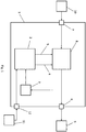
- a power supply unit 1 discloses a feedback control unit 2 selectively controlling the output level of the voltage or the output level of the current to output terminals 6 of the power supply unit 1 on a preset value.
- the feedback control unit 2 is connected to a power circuit 8 or power unit, wherein the power circuit 8 converts an electric current from a source 10 connected to input terminals 7 to the correct voltage, current and frequency to power a load 9 connected to the output terminals 6, wherein the power circuit 8 is connected to the input terminals 7 for receiving for example an electric current from the source 10 and is connected to the output terminals 6 for outputting the voltage, the current or the power for the load 9.
- the power circuit 8 is then controlled by the feedback control unit 2.
- connection between the feedback control unit 2 and the power circuit 8 comprises a part 4 of a current control loop and a part 5 of a voltage control loop, wherein the power circuit 8 is then controlled by the feedback control unit 2 by the current control loop as well as the voltage control loop.
- the load 9 can be for example a power analyzer, wherein the power supply unit 1 can be integrated together with the power analyzer in one housing or can be separately provided in an own housing. Further, it is possible that the power supply unit 1 does not only provide to the power analyzer but also to a DUT connected to the power analyzer voltage, current or power. In this case, the load 9 is therefore the power analyzer together with the DUT.
- the power supply unit 1 further comprises means 3 for sensing the actual output level of the voltage and current, respectively, and sending a signal representing the sensed output level to said feedback control unit 2.
- the means 3 for sensing the actual output level are connected to the output of the power circuit 8. With the signaling representing the sensed output level received from the means 3 for sensing the actual output level, the feedback control unit 2 can then selectively control the power circuit 8 via the part 4 of the current control loop and the part 5 of the voltage control loop and thus, control the voltage, the current or the power supplied at the output of the power circuit 8 and thus, at the output terminals 6 for the load 9.
- the means 3 for sensing the actual output level, the feedback control unit 2 and the part 5 form a voltage feedback loop/voltage control loop
- the means 3 for sensing the actual output level, the feedback control unit 2 and the part 4 form a current feedback loop/current control loop.
- the means 3 for sensing the actual output level and the feedback control unit 2 are used in both feedback loops/control loops.
- the feedback control unit 2 now autonomously prioritize or activate the first control loop 4 for the controlling of the output level of the current or the second control loop 5 for the controlling of the output level of the voltage, based on data generated within the power supply unit or externally generated data supplied to the power supply unit.
- the feedback control unit 2 prioritizes or activates the first control loop 4 (current) or the second control loop 5 (voltage) autonomously, transient overshoots or oscillations can be avoided or at least reduced without a manual selection of a priority of one of the control loops 4 or 5, when, for example, a new load 9 or DUT is connected to the power supply unit 1 or the load 9 or DUT is varied.
- This is derivable for example from fig. 5 , where, compared to the fig. 3 and 4 , no more transient overshoots or oscillations exist in the voltage (in difference to fig. 3 ) as well as in the current (in difference to fig. 4 ).
- Prioritizing in the present invention in particular means that one of the control loops 4 or 5 is more weighted than the other one and thus, has more influence than the other one on the controlling of the power circuit 8 by the feedback control unit 2.
- Activating in the present invention in particular means that one of the control loops 4 or 5 is selected and thus, one of the control loops is used for the controlling of the power circuit 8 by the feedback control unit 2.
- the autonomously prioritizing or activating of the first control loop 4 for the controlling of the output level of the current or the second control loop 5 for the controlling of the output level of the voltage by the feedback control unit 2 is done based on data generated within the power supply unit and/or externally generated data supplied to the power supply unit.
- the externally generated data can be data from the DUT or the load 9 connected to the output terminals 6 of the power supply unit 1.
- it can be sensed data, representing the impedance or the capacitance, of the DUT or load 9.
- the impedance or the capacitance of the DUT or load 9 connected to the power supply unit 1 are measured and then transmitted from the DUT or load 9 to the feedback control unit 2 via, for example, a separate connection not shown in detail in fig. 1 .
- the externally generated data are data from a database.
- the power supply unit 1 is connected to database 11, wherein the power supply unit 1 comprises a network interface 12 that is used for connecting to the database 11.
- the externally generated data is then derivable, which are used by the feedback control unit 2 for autonomously prioritizing or activating the first control loop 4 for the controlling of the output level of the current or the second control loop 5 for the controlling of the output level of the voltage.
- the externally generated data in the database 11 can be for example test sequence data, DUT data, control loop parameters, test parameters or test limits.
- the externally generated data are data of a user input, for example via a corresponding input unit connected to the power supply unit 1 or integrated in the power supply unit 1.
- the data generated within the power supply unit 1 can be sensor data, preferably representing an electrical parameter, such as voltage, current or power transmission, of the status of the output terminals 6, for example data sensed by the means 3 for sensing the actual output level of the voltage and current.
- an electrical parameter such as voltage, current or power transmission
- the data generated within the power supply unit 1 are data from a database 11 positioned in the power supply unit 1, as it is shown in fig. 2 . From the database 11 in the power supply unit 1 the data is then derivable, which is used by the feedback control unit 2 for autonomously prioritizing or activating the first control loop 4 for the controlling of the output level of the current or the second control loop 5 for the controlling of the output level of the voltage. Similar, the data in the database 11 in the power supply unit 1 can be for example test sequence data, DUT data, control loop parameters, test parameters or test limits.
- the means 3 for sensing the actual output level are positioned separately from the feedback control unit 2.
- the means 3 for sensing the actual output level can be placed in the feedback control unit 2, wherein then the feedback control unit 2 is directly connected to the output of the power circuit 8.
- fig. 2 which shows a power supply unit 1 similar to that shown in fig. 1 , comprising a feedback control unit 2, means 3 for sensing the actual output level, output terminals 6, input terminals 7 and a power circuit 8, wherein the power circuit 8 converts an electric current from a source 10 connected to input terminals 7 to the correct voltage, current and frequency to power a load 9 connected to the output terminals 6.
- the only difference between the power supply unit 1 in fig. 2 and the power supply unit 1 in fig. 1 is that in the power supply unit 1 in fig. 2 the means 3 for sensing the actual output level are placed in the feedback control unit 2 and the database 11 is placed in the power supply unit 1. Otherwise, the power supply unit 1 in fig. 2 and the power supply unit 1 in fig. 1 work in a similar way.
- the means 3 for sensing the actual output level are placed separately from the feedback control unit 2 as shown in fig. 1 and the database 11 is placed in the power supply unit 1 as shown in fig. 2 , or that the means 3 for sensing the actual output level are placed in the power supply unit 1 as shown in fig. 2 and the database 11 is placed separately from the feedback control unit 2 as shown in fig. 1 using the network interface 12.
- the data generated within the power supply unit 1 or the externally generated data can be further supplied to an Artificial Intelligence unit (not shown in the figures), such as a trained network, issuing a selection signal for prioritizing or activating the first or the second control loop 4 or 5, respectively.
- the Artificial Intelligence unit can be positioned in the power supply unit 1 or the Artificial Intelligence unit can be externally positioned and the power supply unit 1 is connected to the Artificial Intelligence unit via the network interface 12 or another network interface of the power supply unit 1.
- the feedback control unit 2 can use one or any combination of the above described data generated within the power supply unit 1 and the externally generated data for autonomously prioritizing or activating the first control loop 4 for the controlling of the output level of the current or the second control loop 5 for the controlling of the output level of the voltage.
- the feedback control unit 2 can adjust at least one control parameter value of the prioritized or activated control loop 4 or 5, preferably also based on data generated within the power supply unit 1 or externally generated data supplied to the power supply unit 1.
- the power supply unit 1 can also comprise a further third control loop (not shown in the figures), for example for the power, wherein the feedback control unit 2 then autonomously prioritizes or activates the first control loop 4, the second control loop 5 or the third control loop.
- the feedback control unit 2 can be for example a microcontroller or microprocessor.
- the load 9 can be integrated together with the power supply unit 1 in one housing or the power supply unit 1 can be separately provided in an own housing.
- both control loops are monitored and then it is determined which one of the control loops should be prioritized or activated so that a transient overshoot or a transient oscillation is avoided or at least reduced.
Landscapes
- Engineering & Computer Science (AREA)
- Physics & Mathematics (AREA)
- General Physics & Mathematics (AREA)
- Power Engineering (AREA)
- Electromagnetism (AREA)
- Radar, Positioning & Navigation (AREA)
- Automation & Control Theory (AREA)
- General Engineering & Computer Science (AREA)
- Dc-Dc Converters (AREA)
- Control Of Voltage And Current In General (AREA)
Abstract
Description
- The present invention relates to a power supply unit, preferably for a power analyzer, a method for operating a power supply unit and a power analyzer comprising a power supply unit, wherein the power supply unit comprises a feedback control unit for selectively controlling the output level of the voltage or the output level of the current to output terminals of the power supply unit on a preset value, and means for sensing the actual output level of the voltage and current, respectively, and sending a signal representing the sensed output level to the feedback control unit.
- A power supply or a power supply unit is a device or assembly for supplying power to devices or assemblies, like an electrical or electronic load, that requires different voltages and currents than those provided by a source, like mains supply or batteries. Some power supply units are separate, standalone pieces of equipment, while others are built into the load appliances that they power. Power supply units are also referred to as electric power converters, since the main function of a power supply unit is to convert electric current from the source to the correct voltage, current and/or frequency to power the connected electric load.
- Power supply units are used in and for a great variety of different electric and electronic devices. One of them are power analyzers. A power analyzer is used to measure the flow of power in an electrical system. Power analyzers are able to measure a variety of parameters associated to power consumption and generation. Power analyzers are used for measuring a host of aspects of electrical power for applications, which include testing power electronics, inverters, motors and drives, lighting, home appliances, office equipment, industrial machinery and more.
- Power supply units are categorized in various ways. One type of a power supply unit is a DC power supply unit, wherein the most common one is a switched-mode power supply (SMPS). The SMPS is powered from a DC source or from an AC source and supplies constant DC voltage to its load. In a SMPS the AC mains input is directly rectified and then filtered to obtain a DC voltage. The resulting DC voltage is then switched on and off at a higher frequency by electronic switching, thus producing an AC current that will pass through a high frequency transformer or inductor. After the inductor or transformer secondary, the high frequency AC is rectified and filtered to produce the DC output voltage.
- A SMPS is for example described in the
EP 2 659 578 A2 - Another power supply is described in the
EP 1 853 985 A2 - A problem that can arise in the above-described power supply units or generally in power supply units with at least two control loops/feedback control loops, for example a voltage control loop and a current control loop, is that depending on which one of the control loops is selected/prioritized, there is a risk that in the other control loop respectively the other variable (the voltage or the current) a transient overshoot/oscillation occurs, which could even destroy the load or the device under test (DUT) connected to the power supply unit.
- In general, when a stationary process is excited by a change (like a load change or connecting a load to the power supply unit) a free oscillation occurs and, as a result of damping (according to, for example, feedback control), a new stationary process decays (oscillating) or becomes aperiodic (creeping).
- A transient overshoot/oscillation can for example arise when the load or the DUT connected to the power supply unit varies or a load or DUT is connected to the power supply unit, due to necessary adjustment processes. Such a transient overshoot/oscillation is for example shown in the
figures 3 and 4 , wherein infig. 3 , a transient overshoot of thevoltage 13, respectively a voltage transient oscillation, is shown, whereas inFig. 4 , a transient overshoot of the current 14, respectively a current transient oscillation, is shown. - Presently, such problems are addressed by manual selection of the priority of one of the feedback control loops.
- It is an object of the present invention to provide a power supply unit that avoids transient overshoots or oscillations when, for example, a new load or DUT is connected to the power supply unit or the load or DUT is varied, without a manual selection of a priority of a feedback control loop.
- This object is achieved by means of the features of the independent claims. The dependent claims further develop the central idea of the present invention.
- The present invention relates to a power supply unit, preferably for a power analyzer, comprising a feedback control unit arranged for selectively controlling the output level of the voltage or the output level of the current to output terminals of the power supply unit on a preset value, and means for sensing the actual output level of the voltage and current, respectively, and sending a signal representing the sensed output level to said feedback control unit, wherein the feedback control unit is arranged to autonomously prioritize or activate at least a first control loop for the controlling of the output level of the current or a second control loop for the controlling of the output level of the voltage, based on data generated within the power supply unit and/or externally generated data supplied to the power supply unit.
- Advantageously, the externally generated data are data from a DUT or a load connected to the output terminals of the power supply unit, wherein the externally generated data can be sensed data, preferably representing the impedance or the capacitance, of the DUT or load. It is also possible that the externally generated data are data from a database connected to the power supply unit via a network interface of the power supply unit.
- In a preferred embodiment, the data generated within the power supply unit are sensor data, preferably representing an electrical parameter, such as voltage, current or power transmission, of the status of the output terminals. It is also possible that the data generated within the power supply unit are data from a database in the power supply unit.
- In a preferred embodiment, the data generated within the power supply unit or externally generated data are supplied to an Artificial Intelligence unit, such as a trained network, issuing a selection signal for prioritizing or activating the first or the second control loop, respectively.
- The Artificial Intelligence unit can be positioned in the power supply unit or the Artificial Intelligence unit can be externally positioned and the power supply unit is connected to the Artificial Intelligence unit via a network interface of the power supply unit.
- In a preferred embodiment, the feedback control unit is furthermore arranged to adjust at least one control parameter value of the prioritized or activated control loop, preferably also based on data generated within the power supply unit or externally generated data supplied to the power supply unit.
- Advantageously, the power supply unit is a DC power supply and the feedback control unit comprises an analogue or a digital control algorithm.
- The present invention further relates to a power analyzer comprising the above power supply unit.
- The present invention further relates to a method for operating a power supply unit, preferably for a power analyzer, comprising selectively feedback controlling the output level of the voltage or the output level of the current to output terminals of the power supply unit on a preset value, sensing the actual output level of the voltage and current, respectively, for the selectively feedback controlling, and autonomously prioritizing or activating at least a first control loop for the controlling of the output level of the current or a second control loop for the controlling of the output level of the voltage, based on data generated within the power supply unit or externally generated data supplied to the power supply unit.
- Advantageously, the method further comprises supplying to an Artificial Intelligence unit, such as a trained network, the data generated within the power supply unit or externally generated data and issuing a selection signal for prioritizing or activating the first or the second control loop, respectively.
- In a preferred embodiment, the method further comprises adjusting at least one control parameter value of the prioritized or activated control loop, preferably also based on data generated within the power supply unit or externally generated data supplied to the power supply unit.
- With the power supply unit and the method for operating a power supply unit of the present invention, the feedback control unit autonomously prioritizes or activates a voltage control loop or a current control loop, wherein both control loops are monitored to determine which one of the feedback control loops (the current or the voltage) should be activated or should have priority, so that a transient overshoot of the voltage or current or a voltage transient oscillation or a current transient oscillation is avoided or at least reduced, and thus, it is avoided that a load or a DUT connected to the power supply unit is destroyed.
- These and other aspects and advantages of the present invention will become more apparent when studying the following detailed description, in connection with the figures in which:
- Figure 1
- shows schematically a power supply unit;
- Figure 2
- shows schematically another power supply unit;
- Figure 3
- shows schematically a diagram of a transient overshoot of a voltage;
- Figure 4
- shows schematically a diagram of a transient overshoot of the current; and
- Figure 5
- shows schematically a diagram without a transient overshoot of the voltage and the current.
- As already described above, a power supply unit, for example used in or for a power analyzer, can have at least two feedback control loops, like a voltage control loop and a current control loop. In case one of the two control loops is prioritized, it could happen that a transient overshoot or a transient oscillation in the variable of the other one occurs. Such transient overshoots or transient oscillations are shown for example in the
Figures 3 and 4 , whereinFig. 3 shows a transient overshoot of thevoltage 13, whereas inFig. 4 , a transient overshoot of the current 14 is shown. In both cases it could even happen that parts of the power supply unit or the load/DUT connected to the power supply unit are destroyed. - In the present invention both control loops are now monitored and then it is determined, which one of the control loops should be prioritized or activated so that a transient overshoot or a transient oscillation is avoided or at least reduced. Therefore, as shown in
figure 1 , apower supply unit 1 according to the present invention discloses afeedback control unit 2 selectively controlling the output level of the voltage or the output level of the current tooutput terminals 6 of thepower supply unit 1 on a preset value. - The
feedback control unit 2 is connected to apower circuit 8 or power unit, wherein thepower circuit 8 converts an electric current from asource 10 connected toinput terminals 7 to the correct voltage, current and frequency to power aload 9 connected to theoutput terminals 6, wherein thepower circuit 8 is connected to theinput terminals 7 for receiving for example an electric current from thesource 10 and is connected to theoutput terminals 6 for outputting the voltage, the current or the power for theload 9. Thepower circuit 8 is then controlled by thefeedback control unit 2. - The connection between the
feedback control unit 2 and thepower circuit 8 comprises apart 4 of a current control loop and apart 5 of a voltage control loop, wherein thepower circuit 8 is then controlled by thefeedback control unit 2 by the current control loop as well as the voltage control loop. - Regarding the
load 9, it should be noted that theload 9 can be for example a power analyzer, wherein thepower supply unit 1 can be integrated together with the power analyzer in one housing or can be separately provided in an own housing. Further, it is possible that thepower supply unit 1 does not only provide to the power analyzer but also to a DUT connected to the power analyzer voltage, current or power. In this case, theload 9 is therefore the power analyzer together with the DUT. - The
power supply unit 1 further comprisesmeans 3 for sensing the actual output level of the voltage and current, respectively, and sending a signal representing the sensed output level to saidfeedback control unit 2. Themeans 3 for sensing the actual output level are connected to the output of thepower circuit 8. With the signaling representing the sensed output level received from themeans 3 for sensing the actual output level, thefeedback control unit 2 can then selectively control thepower circuit 8 via thepart 4 of the current control loop and thepart 5 of the voltage control loop and thus, control the voltage, the current or the power supplied at the output of thepower circuit 8 and thus, at theoutput terminals 6 for theload 9. - Therefore, as can be also seen from
fig. 1 , themeans 3 for sensing the actual output level, thefeedback control unit 2 and thepart 5 form a voltage feedback loop/voltage control loop, whereas themeans 3 for sensing the actual output level, thefeedback control unit 2 and thepart 4 form a current feedback loop/current control loop. Themeans 3 for sensing the actual output level and thefeedback control unit 2 are used in both feedback loops/control loops. - According to the present invention, the
feedback control unit 2 now autonomously prioritize or activate thefirst control loop 4 for the controlling of the output level of the current or thesecond control loop 5 for the controlling of the output level of the voltage, based on data generated within the power supply unit or externally generated data supplied to the power supply unit. - Since the
feedback control unit 2 prioritizes or activates the first control loop 4 (current) or the second control loop 5 (voltage) autonomously, transient overshoots or oscillations can be avoided or at least reduced without a manual selection of a priority of one of thecontrol loops new load 9 or DUT is connected to thepower supply unit 1 or theload 9 or DUT is varied. This is derivable for example fromfig. 5 , where, compared to thefig. 3 and 4 , no more transient overshoots or oscillations exist in the voltage (in difference tofig. 3 ) as well as in the current (in difference tofig. 4 ). - Prioritizing in the present invention in particular means that one of the
control loops power circuit 8 by thefeedback control unit 2. - Activating in the present invention in particular means that one of the
control loops power circuit 8 by thefeedback control unit 2. - The autonomously prioritizing or activating of the
first control loop 4 for the controlling of the output level of the current or thesecond control loop 5 for the controlling of the output level of the voltage by thefeedback control unit 2 is done based on data generated within the power supply unit and/or externally generated data supplied to the power supply unit. - The externally generated data can be data from the DUT or the
load 9 connected to theoutput terminals 6 of thepower supply unit 1. In particular, it can be sensed data, representing the impedance or the capacitance, of the DUT orload 9. In this case, the impedance or the capacitance of the DUT orload 9 connected to thepower supply unit 1 are measured and then transmitted from the DUT orload 9 to thefeedback control unit 2 via, for example, a separate connection not shown in detail infig. 1 . - It is also possible that the externally generated data are data from a database. For this, the
power supply unit 1 is connected todatabase 11, wherein thepower supply unit 1 comprises anetwork interface 12 that is used for connecting to thedatabase 11. From thedatabase 11 the externally generated data is then derivable, which are used by thefeedback control unit 2 for autonomously prioritizing or activating thefirst control loop 4 for the controlling of the output level of the current or thesecond control loop 5 for the controlling of the output level of the voltage. The externally generated data in thedatabase 11 can be for example test sequence data, DUT data, control loop parameters, test parameters or test limits. - Further, it is also possible that the externally generated data are data of a user input, for example via a corresponding input unit connected to the
power supply unit 1 or integrated in thepower supply unit 1. - The data generated within the
power supply unit 1 can be sensor data, preferably representing an electrical parameter, such as voltage, current or power transmission, of the status of theoutput terminals 6, for example data sensed by themeans 3 for sensing the actual output level of the voltage and current. - It is also possible that the data generated within the
power supply unit 1 are data from adatabase 11 positioned in thepower supply unit 1, as it is shown infig. 2 . From thedatabase 11 in thepower supply unit 1 the data is then derivable, which is used by thefeedback control unit 2 for autonomously prioritizing or activating thefirst control loop 4 for the controlling of the output level of the current or thesecond control loop 5 for the controlling of the output level of the voltage. Similar, the data in thedatabase 11 in thepower supply unit 1 can be for example test sequence data, DUT data, control loop parameters, test parameters or test limits. - In the
power supply unit 1 shown infig. 1 themeans 3 for sensing the actual output level are positioned separately from thefeedback control unit 2. - Alternatively, the
means 3 for sensing the actual output level can be placed in thefeedback control unit 2, wherein then thefeedback control unit 2 is directly connected to the output of thepower circuit 8. This is illustrated infig. 2 , which shows apower supply unit 1 similar to that shown infig. 1 , comprising afeedback control unit 2, means 3 for sensing the actual output level,output terminals 6,input terminals 7 and apower circuit 8, wherein thepower circuit 8 converts an electric current from asource 10 connected to inputterminals 7 to the correct voltage, current and frequency to power aload 9 connected to theoutput terminals 6. The only difference between thepower supply unit 1 infig. 2 and thepower supply unit 1 infig. 1 is that in thepower supply unit 1 infig. 2 themeans 3 for sensing the actual output level are placed in thefeedback control unit 2 and thedatabase 11 is placed in thepower supply unit 1. Otherwise, thepower supply unit 1 infig. 2 and thepower supply unit 1 infig. 1 work in a similar way. - Further, it would be also possible that the
means 3 for sensing the actual output level are placed separately from thefeedback control unit 2 as shown infig. 1 and thedatabase 11 is placed in thepower supply unit 1 as shown infig. 2 , or that themeans 3 for sensing the actual output level are placed in thepower supply unit 1 as shown infig. 2 and thedatabase 11 is placed separately from thefeedback control unit 2 as shown infig. 1 using thenetwork interface 12. - The data generated within the
power supply unit 1 or the externally generated data can be further supplied to an Artificial Intelligence unit (not shown in the figures), such as a trained network, issuing a selection signal for prioritizing or activating the first or thesecond control loop power supply unit 1 or the Artificial Intelligence unit can be externally positioned and thepower supply unit 1 is connected to the Artificial Intelligence unit via thenetwork interface 12 or another network interface of thepower supply unit 1. - In the
power supply unit 1 according to the present invention, thefeedback control unit 2 can use one or any combination of the above described data generated within thepower supply unit 1 and the externally generated data for autonomously prioritizing or activating thefirst control loop 4 for the controlling of the output level of the current or thesecond control loop 5 for the controlling of the output level of the voltage. - Furthermore, the
feedback control unit 2 can adjust at least one control parameter value of the prioritized or activatedcontrol loop power supply unit 1 or externally generated data supplied to thepower supply unit 1. - The
power supply unit 1 can also comprise a further third control loop (not shown in the figures), for example for the power, wherein thefeedback control unit 2 then autonomously prioritizes or activates thefirst control loop 4, thesecond control loop 5 or the third control loop. - The
feedback control unit 2 can be for example a microcontroller or microprocessor. - Regarding the
load 9, it should be noted that theload 9 can be integrated together with thepower supply unit 1 in one housing or thepower supply unit 1 can be separately provided in an own housing. - Thus, in the present invention both control loops are monitored and then it is determined which one of the control loops should be prioritized or activated so that a transient overshoot or a transient oscillation is avoided or at least reduced.
Claims (15)
- A power supply unit (1), preferably for a power analyzer, comprising:- a feedback control unit (2) arranged for selectively controlling the output level of the voltage or the output level of the current to output terminals (6) of the power supply unit (1) on a preset value, and- means (3) for sensing the actual output level of the voltage and current, respectively, and sending a signal representing the sensed output level to said feedback control unit (2),wherein the feedback control unit (2) is arranged to autonomously prioritize or activate at least a first control loop (4) for the controlling of the output level of the current or a second control loop (5) for the controlling of the output level of the voltage, based on data generated within the power supply unit (1) and/or externally generated data supplied to the power supply unit (1).
- The power supply unit of claim 1, wherein the externally generated data are data from a device under test, DUT, or a load (9) connected to the output terminals (6) of the power supply unit (1).
- The power supply unit of claim 2, wherein the externally generated data are sensed data, preferably representing the impedance or the capacitance, of said DUT or load (9).
- The power supply unit of any of the preceding claims, wherein the data generated within the power supply unit (1) are sensor data, preferably representing an electrical parameter, such as voltage, current or power transmission, of the status of the output terminals (6).
- The power supply unit of any of the preceding claims, wherein the externally generated data are data from a database (11) connected to the power supply unit (1) via a network interface (12) of the power supply unit (1).
- The power supply unit of any of the preceding claims, wherein the data generated within the power supply unit (1) are data from a database (11) in the power supply unit (1).
- The power supply unit of any of the preceding claims, wherein the data generated within the power supply unit (1) or externally generated data are supplied to an Artificial Intelligence unit, such as a trained network, issuing a selection signal for prioritizing or activating the first or the second control loop (4, 5), respectively.
- The power supply unit of claim 8, wherein Artificial Intelligence unit is positioned in the power supply unit (1) or wherein the Artificial Intelligence unit is externally positioned and the power supply unit (1) is connected to the Artificial Intelligence unit via a network interface (11) of the power supply unit (1).
- The power supply unit of any of the preceding claims, wherein the feedback control unit (2) is furthermore arranged to adjust at least one control parameter value of the prioritized or activated control loop (4, 5), preferably also based on data generated within the power supply unit (1) or externally generated data supplied to the power supply unit (1).
- The power supply unit of any of the preceding claims, which is a DC power supply.
- The power supply unit of any of the preceding claims, wherein the feedback control unit (2) comprises an analogue or a digital control algorithm.
- A power analyzer comprising a power supply unit (1) according to any of the claims 1-11.
- A method for operating a power supply unit (1), preferably for a power analyzer, comprising:- selectively feedback controlling the output level of the voltage or the output level of the current to output terminals (6) of the power supply unit (1) on a preset value,- sensing the actual output level of the voltage and current, respectively, for the selectively feedback controlling, and- autonomously prioritizing or activating at least a first control loop (4) for the controlling of the output level of the current or a second control loop (5) for the controlling of the output level of the voltage, based on data generated within the power supply unit (1) or externally generated data supplied to the power supply unit (1).
- The method of claim 13, further comprising supplying to an Artificial Intelligence unit, such as a trained network, the data generated within the power supply unit (1) or externally generated data and issuing a selection signal for prioritizing or activating the first or the second control loop (4, 5), respectively.
- The power supply unit of claim 13 or 14, further comprising adjusting at least one control parameter value of the prioritized or activated control loop (4, 5), preferably also based on data generated within the power supply unit (1) or externally generated data supplied to the power supply unit (1).
Priority Applications (3)
| Application Number | Priority Date | Filing Date | Title |
|---|---|---|---|
| EP19213715.6A EP3832869B8 (en) | 2019-12-05 | 2019-12-05 | Power supply unit with adaptive feedback control loops |
| CN202010753925.9A CN112928899A (en) | 2019-12-05 | 2020-07-30 | Power supply unit with adaptive feedback control loop |
| US17/013,027 US20210173420A1 (en) | 2019-12-05 | 2020-09-04 | Power supply unit with adaptive feedback control loops |
Applications Claiming Priority (1)
| Application Number | Priority Date | Filing Date | Title |
|---|---|---|---|
| EP19213715.6A EP3832869B8 (en) | 2019-12-05 | 2019-12-05 | Power supply unit with adaptive feedback control loops |
Publications (3)
| Publication Number | Publication Date |
|---|---|
| EP3832869A1 true EP3832869A1 (en) | 2021-06-09 |
| EP3832869B1 EP3832869B1 (en) | 2022-02-23 |
| EP3832869B8 EP3832869B8 (en) | 2022-03-30 |
Family
ID=68806592
Family Applications (1)
| Application Number | Title | Priority Date | Filing Date |
|---|---|---|---|
| EP19213715.6A Active EP3832869B8 (en) | 2019-12-05 | 2019-12-05 | Power supply unit with adaptive feedback control loops |
Country Status (3)
| Country | Link |
|---|---|
| US (1) | US20210173420A1 (en) |
| EP (1) | EP3832869B8 (en) |
| CN (1) | CN112928899A (en) |
Families Citing this family (2)
| Publication number | Priority date | Publication date | Assignee | Title |
|---|---|---|---|---|
| US11171558B2 (en) * | 2019-12-20 | 2021-11-09 | Rohde & Schwarz Gmbh & Co. Kg | DC power supply with adaptive controlled preregulator and postregulator |
| WO2023082183A1 (en) * | 2021-11-12 | 2023-05-19 | Aes Global Holdings Pte Ltd. | Apparatus and method for max current sharing |
Citations (10)
| Publication number | Priority date | Publication date | Assignee | Title |
|---|---|---|---|---|
| US3769568A (en) * | 1972-07-31 | 1973-10-30 | Bell Telephone Labor Inc | Dc-to-dc converter having soft start and other regulation features employing priority of pulse feedback |
| EP0339551A2 (en) * | 1988-04-25 | 1989-11-02 | Kabushiki Kaisha Toshiba | Control apparatus of resistance welders and control method thereof |
| DE19545531A1 (en) * | 1994-12-14 | 1996-06-27 | Motorola Inc | Voltage and current mode power regulator for e.g. radiotelephones |
| US20010043079A1 (en) * | 2000-05-19 | 2001-11-22 | Nec Corporation | Screening of semiconductor integrated circuit devices |
| EP1853985A2 (en) | 2005-02-17 | 2007-11-14 | Qualcomm Incorporated | Power supply circuit having voltage control loop and current control loop |
| JP2011139594A (en) * | 2009-12-28 | 2011-07-14 | Fuji Electric Co Ltd | System interconnection system |
| US20130221875A1 (en) * | 2012-02-24 | 2013-08-29 | Richtek Technology Corporation | Light emitting device driver circuit and control method thereof |
| EP2659578A2 (en) | 2010-12-29 | 2013-11-06 | Microchip Technology Incorporated | Adaptive digital modification of analog feedback loop in switch-mode power converter |
| DE102014223377A1 (en) * | 2014-11-17 | 2016-05-19 | Tridonic Gmbh & Co Kg | Operating circuit for supplying a light source, LED converter, system and method for operating an operating circuit |
| CN106300966B (en) * | 2016-10-18 | 2018-10-30 | 成都前锋电子仪器有限责任公司 | One kind being used for power analysis instrument power module |
Family Cites Families (2)
| Publication number | Priority date | Publication date | Assignee | Title |
|---|---|---|---|---|
| US9118239B2 (en) * | 2012-03-29 | 2015-08-25 | Texas Instruments Incorporated | Power supply control method for constant current constant power control |
| WO2019133381A1 (en) * | 2017-12-29 | 2019-07-04 | Verily Life Sciences Llc | High-efficiency power amplifier system for wireless power transmitters |
-
2019
- 2019-12-05 EP EP19213715.6A patent/EP3832869B8/en active Active
-
2020
- 2020-07-30 CN CN202010753925.9A patent/CN112928899A/en active Pending
- 2020-09-04 US US17/013,027 patent/US20210173420A1/en not_active Abandoned
Patent Citations (10)
| Publication number | Priority date | Publication date | Assignee | Title |
|---|---|---|---|---|
| US3769568A (en) * | 1972-07-31 | 1973-10-30 | Bell Telephone Labor Inc | Dc-to-dc converter having soft start and other regulation features employing priority of pulse feedback |
| EP0339551A2 (en) * | 1988-04-25 | 1989-11-02 | Kabushiki Kaisha Toshiba | Control apparatus of resistance welders and control method thereof |
| DE19545531A1 (en) * | 1994-12-14 | 1996-06-27 | Motorola Inc | Voltage and current mode power regulator for e.g. radiotelephones |
| US20010043079A1 (en) * | 2000-05-19 | 2001-11-22 | Nec Corporation | Screening of semiconductor integrated circuit devices |
| EP1853985A2 (en) | 2005-02-17 | 2007-11-14 | Qualcomm Incorporated | Power supply circuit having voltage control loop and current control loop |
| JP2011139594A (en) * | 2009-12-28 | 2011-07-14 | Fuji Electric Co Ltd | System interconnection system |
| EP2659578A2 (en) | 2010-12-29 | 2013-11-06 | Microchip Technology Incorporated | Adaptive digital modification of analog feedback loop in switch-mode power converter |
| US20130221875A1 (en) * | 2012-02-24 | 2013-08-29 | Richtek Technology Corporation | Light emitting device driver circuit and control method thereof |
| DE102014223377A1 (en) * | 2014-11-17 | 2016-05-19 | Tridonic Gmbh & Co Kg | Operating circuit for supplying a light source, LED converter, system and method for operating an operating circuit |
| CN106300966B (en) * | 2016-10-18 | 2018-10-30 | 成都前锋电子仪器有限责任公司 | One kind being used for power analysis instrument power module |
Also Published As
| Publication number | Publication date |
|---|---|
| EP3832869B8 (en) | 2022-03-30 |
| CN112928899A (en) | 2021-06-08 |
| EP3832869B1 (en) | 2022-02-23 |
| US20210173420A1 (en) | 2021-06-10 |
Similar Documents
| Publication | Publication Date | Title |
|---|---|---|
| US7944090B2 (en) | Multi-output power conversion circuit | |
| US5063489A (en) | Switching regulator having improved switching control arrangement | |
| EP3443652B1 (en) | Voltage droop control in a voltage-regulated switched mode power supply | |
| CN103036395B (en) | Isolated switch mode power supply and optimizing gain adjustment value therein | |
| US5880580A (en) | Automatic regulation of power delivered by ultrasonic transducer | |
| EP0172891B1 (en) | Soft-start control for a push-pull converter-regulator with a flux balancing circuit | |
| KR20120084318A (en) | Feedback circuit for zero-voltage-switching converter | |
| EP3832869B1 (en) | Power supply unit with adaptive feedback control loops | |
| US5267134A (en) | Voltage and frequency converter device | |
| US11489448B2 (en) | Isolated switching converter with high feedback accuracy and control method | |
| EP2626993A1 (en) | Switch mode power supply module and associated hiccup control method | |
| CN119718041A (en) | Power supply system of server | |
| US11239688B2 (en) | Power supply unit with adaptive feedback control | |
| CN102255480B (en) | Power conversion device and pulse width modulation signal control device thereof | |
| KR940007474B1 (en) | Driving voltage apparatus of magnetron | |
| KR101128960B1 (en) | Bus loop power interface and method | |
| EP2804303B1 (en) | Switching power supply circuit | |
| US7392405B2 (en) | Digitally controlled power supply | |
| JP2004031346A (en) | Circuit device for X-ray tube voltage generation | |
| RU2215360C2 (en) | Method and device for regulating output current of stabilizing pulse converter | |
| US11171558B2 (en) | DC power supply with adaptive controlled preregulator and postregulator | |
| JPWO2016166976A1 (en) | Converter and power receiving device | |
| KR100487390B1 (en) | Switched-mode power supply device with a starting circuit | |
| KR200452181Y1 (en) | Voltage regulation remote monitoring and control device for high voltage control using sine wave inverter and programmable logic controller | |
| EP3518403B1 (en) | Device for eliminating slope in output voltage of switcher power converter in plc module |
Legal Events
| Date | Code | Title | Description |
|---|---|---|---|
| PUAI | Public reference made under article 153(3) epc to a published international application that has entered the european phase |
Free format text: ORIGINAL CODE: 0009012 |
|
| STAA | Information on the status of an ep patent application or granted ep patent |
Free format text: STATUS: EXAMINATION IS IN PROGRESS |
|
| 17P | Request for examination filed |
Effective date: 20200826 |
|
| AK | Designated contracting states |
Kind code of ref document: A1 Designated state(s): AL AT BE BG CH CY CZ DE DK EE ES FI FR GB GR HR HU IE IS IT LI LT LU LV MC MK MT NL NO PL PT RO RS SE SI SK SM TR |
|
| GRAP | Despatch of communication of intention to grant a patent |
Free format text: ORIGINAL CODE: EPIDOSNIGR1 |
|
| STAA | Information on the status of an ep patent application or granted ep patent |
Free format text: STATUS: GRANT OF PATENT IS INTENDED |
|
| GRAJ | Information related to disapproval of communication of intention to grant by the applicant or resumption of examination proceedings by the epo deleted |
Free format text: ORIGINAL CODE: EPIDOSDIGR1 |
|
| GRAP | Despatch of communication of intention to grant a patent |
Free format text: ORIGINAL CODE: EPIDOSNIGR1 |
|
| GRAS | Grant fee paid |
Free format text: ORIGINAL CODE: EPIDOSNIGR3 |
|
| INTG | Intention to grant announced |
Effective date: 20211013 |
|
| INTG | Intention to grant announced |
Effective date: 20211026 |
|
| GRAA | (expected) grant |
Free format text: ORIGINAL CODE: 0009210 |
|
| STAA | Information on the status of an ep patent application or granted ep patent |
Free format text: STATUS: THE PATENT HAS BEEN GRANTED |
|
| AK | Designated contracting states |
Kind code of ref document: B1 Designated state(s): AL AT BE BG CH CY CZ DE DK EE ES FI FR GB GR HR HU IE IS IT LI LT LU LV MC MK MT NL NO PL PT RO RS SE SI SK SM TR |
|
| REG | Reference to a national code |
Ref country code: GB Ref legal event code: FG4D |
|
| REG | Reference to a national code |
Ref country code: DE Ref legal event code: R096 Ref document number: 602019011840 Country of ref document: DE |
|
| REG | Reference to a national code |
Ref country code: AT Ref legal event code: REF Ref document number: 1471218 Country of ref document: AT Kind code of ref document: T Effective date: 20220315 |
|
| RBV | Designated contracting states (corrected) |
Designated state(s): AL AT BE BG CY CZ DE DK EE ES FI FR GB GR HR HU IS IT LT LU LV MC MK MT NL NO PL PT RO RS SE SI SK SM TR |
|
| REG | Reference to a national code |
Ref country code: IE Ref legal event code: FG4D |
|
| REG | Reference to a national code |
Ref country code: LT Ref legal event code: MG9D |
|
| REG | Reference to a national code |
Ref country code: NL Ref legal event code: MP Effective date: 20220223 |
|
| REG | Reference to a national code |
Ref country code: AT Ref legal event code: MK05 Ref document number: 1471218 Country of ref document: AT Kind code of ref document: T Effective date: 20220223 |
|
| PG25 | Lapsed in a contracting state [announced via postgrant information from national office to epo] |
Ref country code: SE Free format text: LAPSE BECAUSE OF FAILURE TO SUBMIT A TRANSLATION OF THE DESCRIPTION OR TO PAY THE FEE WITHIN THE PRESCRIBED TIME-LIMIT Effective date: 20220223 Ref country code: RS Free format text: LAPSE BECAUSE OF FAILURE TO SUBMIT A TRANSLATION OF THE DESCRIPTION OR TO PAY THE FEE WITHIN THE PRESCRIBED TIME-LIMIT Effective date: 20220223 Ref country code: PT Free format text: LAPSE BECAUSE OF FAILURE TO SUBMIT A TRANSLATION OF THE DESCRIPTION OR TO PAY THE FEE WITHIN THE PRESCRIBED TIME-LIMIT Effective date: 20220623 Ref country code: NO Free format text: LAPSE BECAUSE OF FAILURE TO SUBMIT A TRANSLATION OF THE DESCRIPTION OR TO PAY THE FEE WITHIN THE PRESCRIBED TIME-LIMIT Effective date: 20220523 Ref country code: NL Free format text: LAPSE BECAUSE OF FAILURE TO SUBMIT A TRANSLATION OF THE DESCRIPTION OR TO PAY THE FEE WITHIN THE PRESCRIBED TIME-LIMIT Effective date: 20220223 Ref country code: LT Free format text: LAPSE BECAUSE OF FAILURE TO SUBMIT A TRANSLATION OF THE DESCRIPTION OR TO PAY THE FEE WITHIN THE PRESCRIBED TIME-LIMIT Effective date: 20220223 Ref country code: HR Free format text: LAPSE BECAUSE OF FAILURE TO SUBMIT A TRANSLATION OF THE DESCRIPTION OR TO PAY THE FEE WITHIN THE PRESCRIBED TIME-LIMIT Effective date: 20220223 Ref country code: ES Free format text: LAPSE BECAUSE OF FAILURE TO SUBMIT A TRANSLATION OF THE DESCRIPTION OR TO PAY THE FEE WITHIN THE PRESCRIBED TIME-LIMIT Effective date: 20220223 Ref country code: BG Free format text: LAPSE BECAUSE OF FAILURE TO SUBMIT A TRANSLATION OF THE DESCRIPTION OR TO PAY THE FEE WITHIN THE PRESCRIBED TIME-LIMIT Effective date: 20220523 |
|
| PG25 | Lapsed in a contracting state [announced via postgrant information from national office to epo] |
Ref country code: PL Free format text: LAPSE BECAUSE OF FAILURE TO SUBMIT A TRANSLATION OF THE DESCRIPTION OR TO PAY THE FEE WITHIN THE PRESCRIBED TIME-LIMIT Effective date: 20220223 Ref country code: LV Free format text: LAPSE BECAUSE OF FAILURE TO SUBMIT A TRANSLATION OF THE DESCRIPTION OR TO PAY THE FEE WITHIN THE PRESCRIBED TIME-LIMIT Effective date: 20220223 Ref country code: GR Free format text: LAPSE BECAUSE OF FAILURE TO SUBMIT A TRANSLATION OF THE DESCRIPTION OR TO PAY THE FEE WITHIN THE PRESCRIBED TIME-LIMIT Effective date: 20220524 Ref country code: FI Free format text: LAPSE BECAUSE OF FAILURE TO SUBMIT A TRANSLATION OF THE DESCRIPTION OR TO PAY THE FEE WITHIN THE PRESCRIBED TIME-LIMIT Effective date: 20220223 Ref country code: AT Free format text: LAPSE BECAUSE OF FAILURE TO SUBMIT A TRANSLATION OF THE DESCRIPTION OR TO PAY THE FEE WITHIN THE PRESCRIBED TIME-LIMIT Effective date: 20220223 |
|
| PG25 | Lapsed in a contracting state [announced via postgrant information from national office to epo] |
Ref country code: IS Free format text: LAPSE BECAUSE OF FAILURE TO SUBMIT A TRANSLATION OF THE DESCRIPTION OR TO PAY THE FEE WITHIN THE PRESCRIBED TIME-LIMIT Effective date: 20220623 |
|
| PG25 | Lapsed in a contracting state [announced via postgrant information from national office to epo] |
Ref country code: SM Free format text: LAPSE BECAUSE OF FAILURE TO SUBMIT A TRANSLATION OF THE DESCRIPTION OR TO PAY THE FEE WITHIN THE PRESCRIBED TIME-LIMIT Effective date: 20220223 Ref country code: SK Free format text: LAPSE BECAUSE OF FAILURE TO SUBMIT A TRANSLATION OF THE DESCRIPTION OR TO PAY THE FEE WITHIN THE PRESCRIBED TIME-LIMIT Effective date: 20220223 Ref country code: RO Free format text: LAPSE BECAUSE OF FAILURE TO SUBMIT A TRANSLATION OF THE DESCRIPTION OR TO PAY THE FEE WITHIN THE PRESCRIBED TIME-LIMIT Effective date: 20220223 Ref country code: EE Free format text: LAPSE BECAUSE OF FAILURE TO SUBMIT A TRANSLATION OF THE DESCRIPTION OR TO PAY THE FEE WITHIN THE PRESCRIBED TIME-LIMIT Effective date: 20220223 Ref country code: DK Free format text: LAPSE BECAUSE OF FAILURE TO SUBMIT A TRANSLATION OF THE DESCRIPTION OR TO PAY THE FEE WITHIN THE PRESCRIBED TIME-LIMIT Effective date: 20220223 Ref country code: CZ Free format text: LAPSE BECAUSE OF FAILURE TO SUBMIT A TRANSLATION OF THE DESCRIPTION OR TO PAY THE FEE WITHIN THE PRESCRIBED TIME-LIMIT Effective date: 20220223 |
|
| REG | Reference to a national code |
Ref country code: DE Ref legal event code: R097 Ref document number: 602019011840 Country of ref document: DE |
|
| PG25 | Lapsed in a contracting state [announced via postgrant information from national office to epo] |
Ref country code: AL Free format text: LAPSE BECAUSE OF FAILURE TO SUBMIT A TRANSLATION OF THE DESCRIPTION OR TO PAY THE FEE WITHIN THE PRESCRIBED TIME-LIMIT Effective date: 20220223 |
|
| PLBE | No opposition filed within time limit |
Free format text: ORIGINAL CODE: 0009261 |
|
| STAA | Information on the status of an ep patent application or granted ep patent |
Free format text: STATUS: NO OPPOSITION FILED WITHIN TIME LIMIT |
|
| 26N | No opposition filed |
Effective date: 20221124 |
|
| P01 | Opt-out of the competence of the unified patent court (upc) registered |
Effective date: 20230525 |
|
| PG25 | Lapsed in a contracting state [announced via postgrant information from national office to epo] |
Ref country code: IT Free format text: LAPSE BECAUSE OF FAILURE TO SUBMIT A TRANSLATION OF THE DESCRIPTION OR TO PAY THE FEE WITHIN THE PRESCRIBED TIME-LIMIT Effective date: 20220223 |
|
| REG | Reference to a national code |
Ref country code: BE Ref legal event code: MM Effective date: 20221231 |
|
| PG25 | Lapsed in a contracting state [announced via postgrant information from national office to epo] |
Ref country code: LU Free format text: LAPSE BECAUSE OF NON-PAYMENT OF DUE FEES Effective date: 20221205 |
|
| PG25 | Lapsed in a contracting state [announced via postgrant information from national office to epo] |
Ref country code: BE Free format text: LAPSE BECAUSE OF NON-PAYMENT OF DUE FEES Effective date: 20221231 |
|
| PG25 | Lapsed in a contracting state [announced via postgrant information from national office to epo] |
Ref country code: CY Free format text: LAPSE BECAUSE OF FAILURE TO SUBMIT A TRANSLATION OF THE DESCRIPTION OR TO PAY THE FEE WITHIN THE PRESCRIBED TIME-LIMIT Effective date: 20220223 |
|
| PG25 | Lapsed in a contracting state [announced via postgrant information from national office to epo] |
Ref country code: MK Free format text: LAPSE BECAUSE OF FAILURE TO SUBMIT A TRANSLATION OF THE DESCRIPTION OR TO PAY THE FEE WITHIN THE PRESCRIBED TIME-LIMIT Effective date: 20220223 Ref country code: HU Free format text: LAPSE BECAUSE OF FAILURE TO SUBMIT A TRANSLATION OF THE DESCRIPTION OR TO PAY THE FEE WITHIN THE PRESCRIBED TIME-LIMIT; INVALID AB INITIO Effective date: 20191205 |
|
| PG25 | Lapsed in a contracting state [announced via postgrant information from national office to epo] |
Ref country code: MC Free format text: LAPSE BECAUSE OF FAILURE TO SUBMIT A TRANSLATION OF THE DESCRIPTION OR TO PAY THE FEE WITHIN THE PRESCRIBED TIME-LIMIT Effective date: 20220223 |
|
| PG25 | Lapsed in a contracting state [announced via postgrant information from national office to epo] |
Ref country code: MC Free format text: LAPSE BECAUSE OF FAILURE TO SUBMIT A TRANSLATION OF THE DESCRIPTION OR TO PAY THE FEE WITHIN THE PRESCRIBED TIME-LIMIT Effective date: 20220223 |
|
| PG25 | Lapsed in a contracting state [announced via postgrant information from national office to epo] |
Ref country code: MT Free format text: LAPSE BECAUSE OF FAILURE TO SUBMIT A TRANSLATION OF THE DESCRIPTION OR TO PAY THE FEE WITHIN THE PRESCRIBED TIME-LIMIT Effective date: 20220223 |
|
| PG25 | Lapsed in a contracting state [announced via postgrant information from national office to epo] |
Ref country code: TR Free format text: LAPSE BECAUSE OF FAILURE TO SUBMIT A TRANSLATION OF THE DESCRIPTION OR TO PAY THE FEE WITHIN THE PRESCRIBED TIME-LIMIT Effective date: 20220223 |
|
| PGFP | Annual fee paid to national office [announced via postgrant information from national office to epo] |
Ref country code: GB Payment date: 20251218 Year of fee payment: 7 |
|
| PGFP | Annual fee paid to national office [announced via postgrant information from national office to epo] |
Ref country code: FR Payment date: 20251218 Year of fee payment: 7 |
|
| PG25 | Lapsed in a contracting state [announced via postgrant information from national office to epo] |
Ref country code: SI Free format text: LAPSE BECAUSE OF FAILURE TO SUBMIT A TRANSLATION OF THE DESCRIPTION OR TO PAY THE FEE WITHIN THE PRESCRIBED TIME-LIMIT Effective date: 20220223 |
|
| PGFP | Annual fee paid to national office [announced via postgrant information from national office to epo] |
Ref country code: DE Payment date: 20251222 Year of fee payment: 7 |