EP3832811A1 - Coaxial cable assemblies having pinching and gripping elements - Google Patents
Coaxial cable assemblies having pinching and gripping elements Download PDFInfo
- Publication number
- EP3832811A1 EP3832811A1 EP20210412.1A EP20210412A EP3832811A1 EP 3832811 A1 EP3832811 A1 EP 3832811A1 EP 20210412 A EP20210412 A EP 20210412A EP 3832811 A1 EP3832811 A1 EP 3832811A1
- Authority
- EP
- European Patent Office
- Prior art keywords
- corrugated
- rear outer
- end portion
- outer body
- connector assembly
- Prior art date
- Legal status (The legal status is an assumption and is not a legal conclusion. Google has not performed a legal analysis and makes no representation as to the accuracy of the status listed.)
- Granted
Links
Images


Classifications
-
- H—ELECTRICITY
- H01—ELECTRIC ELEMENTS
- H01R—ELECTRICALLY-CONDUCTIVE CONNECTIONS; STRUCTURAL ASSOCIATIONS OF A PLURALITY OF MUTUALLY-INSULATED ELECTRICAL CONNECTING ELEMENTS; COUPLING DEVICES; CURRENT COLLECTORS
- H01R24/00—Two-part coupling devices, or either of their cooperating parts, characterised by their overall structure
- H01R24/38—Two-part coupling devices, or either of their cooperating parts, characterised by their overall structure having concentrically or coaxially arranged contacts
- H01R24/40—Two-part coupling devices, or either of their cooperating parts, characterised by their overall structure having concentrically or coaxially arranged contacts specially adapted for high frequency
- H01R24/56—Two-part coupling devices, or either of their cooperating parts, characterised by their overall structure having concentrically or coaxially arranged contacts specially adapted for high frequency specially adapted to a specific shape of cables, e.g. corrugated cables, twisted pair cables, cables with two screens or hollow cables
- H01R24/564—Corrugated cables
-
- H—ELECTRICITY
- H01—ELECTRIC ELEMENTS
- H01R—ELECTRICALLY-CONDUCTIVE CONNECTIONS; STRUCTURAL ASSOCIATIONS OF A PLURALITY OF MUTUALLY-INSULATED ELECTRICAL CONNECTING ELEMENTS; COUPLING DEVICES; CURRENT COLLECTORS
- H01R4/00—Electrically-conductive connections between two or more conductive members in direct contact, i.e. touching one another; Means for effecting or maintaining such contact; Electrically-conductive connections having two or more spaced connecting locations for conductors and using contact members penetrating insulation
- H01R4/10—Electrically-conductive connections between two or more conductive members in direct contact, i.e. touching one another; Means for effecting or maintaining such contact; Electrically-conductive connections having two or more spaced connecting locations for conductors and using contact members penetrating insulation effected solely by twisting, wrapping, bending, crimping, or other permanent deformation
- H01R4/18—Electrically-conductive connections between two or more conductive members in direct contact, i.e. touching one another; Means for effecting or maintaining such contact; Electrically-conductive connections having two or more spaced connecting locations for conductors and using contact members penetrating insulation effected solely by twisting, wrapping, bending, crimping, or other permanent deformation by crimping
- H01R4/183—Electrically-conductive connections between two or more conductive members in direct contact, i.e. touching one another; Means for effecting or maintaining such contact; Electrically-conductive connections having two or more spaced connecting locations for conductors and using contact members penetrating insulation effected solely by twisting, wrapping, bending, crimping, or other permanent deformation by crimping for cylindrical elongated bodies, e.g. cables having circular cross-section
-
- H—ELECTRICITY
- H01—ELECTRIC ELEMENTS
- H01R—ELECTRICALLY-CONDUCTIVE CONNECTIONS; STRUCTURAL ASSOCIATIONS OF A PLURALITY OF MUTUALLY-INSULATED ELECTRICAL CONNECTING ELEMENTS; COUPLING DEVICES; CURRENT COLLECTORS
- H01R43/00—Apparatus or processes specially adapted for manufacturing, assembling, maintaining, or repairing of line connectors or current collectors or for joining electric conductors
- H01R43/04—Apparatus or processes specially adapted for manufacturing, assembling, maintaining, or repairing of line connectors or current collectors or for joining electric conductors for forming connections by deformation, e.g. crimping tool
- H01R43/048—Crimping apparatus or processes
-
- H—ELECTRICITY
- H01—ELECTRIC ELEMENTS
- H01R—ELECTRICALLY-CONDUCTIVE CONNECTIONS; STRUCTURAL ASSOCIATIONS OF A PLURALITY OF MUTUALLY-INSULATED ELECTRICAL CONNECTING ELEMENTS; COUPLING DEVICES; CURRENT COLLECTORS
- H01R9/00—Structural associations of a plurality of mutually-insulated electrical connecting elements, e.g. terminal strips or terminal blocks; Terminals or binding posts mounted upon a base or in a case; Bases therefor
- H01R9/03—Connectors arranged to contact a plurality of the conductors of a multiconductor cable, e.g. tapping connections
- H01R9/05—Connectors arranged to contact a plurality of the conductors of a multiconductor cable, e.g. tapping connections for coaxial cables
- H01R9/0518—Connection to outer conductor by crimping or by crimping ferrule
-
- H—ELECTRICITY
- H01—ELECTRIC ELEMENTS
- H01R—ELECTRICALLY-CONDUCTIVE CONNECTIONS; STRUCTURAL ASSOCIATIONS OF A PLURALITY OF MUTUALLY-INSULATED ELECTRICAL CONNECTING ELEMENTS; COUPLING DEVICES; CURRENT COLLECTORS
- H01R2103/00—Two poles
Definitions
- the rear outer body 202 includes a front end 208, a back end 210, external gripping portions 212a, 212b, a recess 213 positioned between the external gripping portions 212a, 212b, and an outer body opening 214 extending between the front end 208 and the back end 210 with respect to a longitudinal axis A.
- the rear outer body 202 further includes a threaded portion 216 adjacent the front end 208 for engagement with a front subassembly 204, which will be further described.
- the threaded portion 216 is represented schematically by dashed line T1.
- the neck portion 284 has a cross-section that is sufficiently thin and configured to flex, thus allowing the nub portion 286 to move when a force is applied to the front body shell 260.
- the annular shoulder 270 cooperates with the threaded portion 216 of rear outer body 202 to secure the rear outer body 202 to the front subassembly 204.
- the insulator 300 includes a bore 302 aligned with respect to longitudinal axis A and an outer surface 304. In preferred configurations, the insulator 300 further includes an insulator channel 306.
- the insulator 300 is manufactured from an electrically insulative material Examples of such materials include, but are not limited to, foam-based materials and acetal.
- the rear outer body 202 and front subassembly 204 should be separated from one another, i.e., unscrewed from one another in preferred embodiments, before assembly.
- the rear outer body 202 is then placed over the prepared corrugated coaxial cable 100, i.e. after the jacket 130 of the corrugated coaxial cable 100 has been stripped back to expose a portion of the corrugated outer conductor 125.
- the contact element 320 aligns and engages with the inside diameter 110 of the center conductor 105.
Landscapes
- Engineering & Computer Science (AREA)
- Manufacturing & Machinery (AREA)
- Coupling Device And Connection With Printed Circuit (AREA)
Abstract
Description
- This application claims priority to
US Application Serial No. 62/942,742, filed December 2, 2019 US Application Serial No. 63/059,701, filed July 31, 2020 - The present disclosure generally relates to coaxial cable assemblies, and particularly connector assemblies, having pinching and gripping elements, that connect with coaxial cables, having corrugated outer conductors.
- A coaxial cable is characterized by having an inner electrical conductor, an outer electrical conductor, and a dielectric between the inner and outer electrical conductors. The inner electrical conductor may be hollow or solid. At the end of coaxial cable, a connector or connector assembly is attached to allow for mechanical and electrical coupling of the coaxial cable.
- Connectors and connector assemblies for attachment to coaxial cables have been used throughout the coaxial cable industry for a number of years. One type of coaxial cable has an annularly corrugated outer conductor and a plain cylindrical inner conductor. Generally, connectors and connector assemblies that attached to these types of coaxial cables are different from those where the outer electrical conductors are smooth or uncorrugated.
- For example, one connector assembly type includes a single annular clamping portion that meshes with the last valley or outermost valley of the corrugated outer conductor, providing a single circumferential point of contact. Without additional axial reinforcement from the coaxial cable connector, physical gyrations of the cable found in field applications due to weather and vibration can cause undue stress and, ultimately, material fatigue of the corrugated cable outer conductor.
- The aforementioned example clearly shows there is a continuing need for improved high performance coaxial cable connectors and connector assemblies. There is a particular need for connectors and connector assemblies that can be installed and uninstalled easily and quickly, particularly under field conditions. Also, since these connectors and connector assemblies are generally installed in the field, they should be configured for pre-assembly, so that the possibility of dropping and losing small parts, misplacing o-rings, damaging or improperly lubricating o-ring, or other assembly errors in the field are minimized. Additionally, it should be possible for the coaxial cable connector to be installed and removed without the use of any special tools.
- In view of the aforementioned needs, as well as other issues with prior connector and connector assembly designs, alternatives are desired.
- Disclosed herein are various embodiments of coaxial cable connector assemblies for attachment to a corrugated coaxial cable, having a center conductor, a dielectric surrounding the center conductor, and a corrugated outer conductor surrounding the dielectric. Related methods are also disclosed herein.
- According to a first aspect, a coaxial connector assembly, for attachment to a corrugated coaxial cable, includes a rear outer body, having an engagement element, to be received over a portion of the corrugated coaxial cable and a front subassembly. The front subassembly is configured for partial insertion into the rear outer body. The front subassembly includes, among other things, a front body shell, having a deformable end portion and a rearward annular extension spaced apart from the deformable end portion such that a pinching space is formed between the deformable end portion and the rearward annular extension. Upon coupling of the rear outer body with the front body shell, a portion of the corrugated outer conductor is configured for positioning within the pinching space. In addition, during the coupling, the deformable end portion is inwardly urged toward the rearward annular extension by the engagement element such that the portion of the corrugated outer conductor is pinched while positioned within the pinching space.
- According to a second aspect, a coaxial connector assembly includes a front subassembly and an alternative version of a rear outer body to be received over a portion of the corrugated coaxial cable. The rear outer body includes an engagement element that slidingly engages with the corrugated outer conductor upon coupling. The front subassembly is configured for partial insertion into the rear outer body. The front subassembly includes a front body shell, having an end portion and a ferrule spaced apart from the end portion such that a gripping space is formed between the end portion and the ferrule. Upon coupling of the rear outer body (402) with the front body shell, a portion of the corrugated outer conductor is positioned within the gripping space and the ferrule is inwardly urged toward the end portion by the engagement element such that the portion of the corrugated outer conductor is gripped while positioned within the gripping space.
- According to a third aspect, a method of making a connector assembly to be attached to a corrugated coaxial cable includes the steps of: forming a rear outer body to be received over a prepared end of the corrugated coaxial cable, with the rear outer body including an engagement element defined therein; forming a front subassembly to engage the rear outer body, with the front subassembly including a front body shell having a deformable end portion and a rearward annular extension spaced apart from the deformable end portion such that a pinching space is formed between the deformable end portion and the rearward annular extension, coupling the rear outer body with the front body shell, and positioning a portion of the corrugated outer conductor within the pinching space.
- Additional features and advantages will be set forth in the detailed description which follows, and in part will be readily apparent to those skilled in the art from that description or recognized by practicing the embodiments as described herein, including the detailed description which follows, the claims, as well as the appended drawings.
- It is to be understood that both the foregoing general description and the following detailed description are merely exemplary, and are intended to provide an overview or framework to understanding the nature and character of the claims. The accompanying drawings are included to provide a further understanding, and are incorporated in and constitute a part of this specification. The drawings illustrate embodiments, and together with the description serve to explain principles and operation of the various embodiments.
-
-
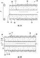
FIG. 1A is an exploded cross-sectional view of a seal-cable assembly; -
FIG. 1B is an assembled cross-sectional view of the seal-cable assembly shown inFIG. 1A ; -
FIG. 2A is a cross-sectional view of the seal-cable assembly shown inFIG. 1A before assembly with a first rear outer body embodiment; -
FIG. 2B is a cross-sectional view of the seal-cable assembly shown inFIG. 1A after assembly with the rear outer body shown inFIG. 2A ; -
FIG. 3 is a cross-sectional view of a first connector subassembly in accordance with embodiments disclosed herein; -
FIG. 4 is a cross-sectional view of the first connector subassembly shown inFIG. 3 assembled with the rear outer body and the seal-cable assembly shown inFIG. 2B ; -
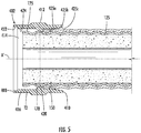
FIG. 5 is a cross-sectional view of the seal-cable assembly shown inFIG. 1A after assembly with a second rear outer body embodiment; -
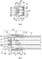
FIG. 6 is a cross-sectional view of a second connector subassembly in accordance with embodiments disclosed herein; -
FIG. 7 is a cross-sectional view of the second connector subassembly shown inFIG. 6 assembled with the rear outer body shown and the seal-cable assembly shown inFIG. 5 ; - The figures are not necessarily to scale. Like numbers used in the figures may be used to refer to like components. However, it will be understood that the use of a number to refer to a component in a given figure is not intended to limit the component in another figure labeled with the same number.
- Various exemplary embodiments of the disclosure will now be described with particular reference to the drawings. Exemplary embodiments of the present disclosure may take on various modifications and alterations without departing from the spirit and scope of the disclosure. Accordingly, it is to be understood that the embodiments of the present disclosure are not to be limited to the following described exemplary embodiments, but are to be controlled by the features and limitations set forth in the claims and any equivalents thereof.
- Unless otherwise indicated, all numbers expressing feature sizes, amounts, and physical properties used in the specification and claims are to be understood as being modified in all instances by the term "about." Accordingly, unless indicated to the contrary, the numerical parameters set forth in the foregoing specification and attached claims are approximations that can vary depending upon the desired properties sought to be obtained by those skilled in the art utilizing the teachings disclosed herein.
- As used in this specification and the appended claims, the singular forms "a," "an," and "the" encompass embodiments having plural referents, unless the content clearly dictates otherwise. As used in this specification and the appended claims, the term "or" is generally employed in its sense including "and/or" unless the content clearly dictates otherwise.
- Spatially related terms, including but not limited to, "lower," "upper," "beneath," "below," "above," and "on top," if used herein, are utilized for ease of description to describe spatial relationships of an element(s) to another. Such spatially related terms encompass different orientations of the device in use or operation in addition to the particular orientations depicted in the figures and described herein. For example, if an object depicted in the figures is turned over or flipped over, portions previously described as below or beneath other elements would then be above those other elements.
- Cartesian coordinates are used in some of the Figures for reference and are not intended to be limiting as to direction or orientation.
- For purposes of description herein, the terms "upper," "lower," "right," "left," "rear," "front," "vertical," "horizontal," "top," "bottom," "side," and derivatives thereof, shall relate to the disclosure as oriented with respect to the Cartesian coordinates in the corresponding Figure, unless stated otherwise. However, it is to be understood that the disclosure may assume various alternative orientations, except where expressly specified to the contrary.
- Disclosed herein are embodiments of
connector assemblies -
FIGs. 1A and 1B show cross sectional views of a portion of a corrugatedcoaxial cable 100 and aseal 150, configured as an o-ring. Specifically,FIG. 1A shows an exploded view of the corrugatedcoaxial cable 100 and theseal 150 andFIG. 1B shows the corrugatedcoaxial cable 100 and theseal 150 assembled to form a cable-seal assembly 160. The cable-seal assembly 160 can be assembled with the connector subassemblies disclosed herein, as will be further described. - The corrugated
coaxial cable 100 includes acenter conductor 105, a dielectric 120, a corrugatedouter conductor 125, and ajacket 130. Thecenter conductor 105 is annular and thus includes aninside diameter 110 and anoutside diameter 115. The dielectric 120 surrounds theoutside diameter 115 of thecenter conductor 105, the corrugatedouter conductor 125 surrounds the dielectric 120, and thejacket 130 surrounds the corrugatedouter conductor 125. In bothFIG. 1A and 1B , aforward end 103 of the corrugatedcoaxial cable 100 is shown in a "prepared state," meaning that an end of the corrugated coaxial cable 100 a portion of thejacket 130 has been removed such that the corrugatedouter conductor 125 is fully exposed and ready for positioning in a connector assembly. - As shown particularly in
FIG. 1B , theseal 150 is configured for positioning adjacent to or within anoutermost valley 126 of the corrugatedouter conductor 125. In this embodiment, theseal 150 is configured as an o-ring, having a circular cross-section. Other seal configurations, with different cross-sectional shapes, however, may be used. - Each embodiment of the connector assemblies disclosed herein is preferably preassembled before shipment and includes a rear outer body and a front subassembly. Each rear outer body and front subassembly are thus attached to one another so that they can be shipped from the factory to the field and then installed onto a prepared end of a corrugated coaxial cable.
-
FIG. 2A shows an exploded view of a rearouter body 202 and a cable-seal assembly 160 with the cable being in a prepared state having aprepared end 170, whileFIG. 2B shows the rearouter body 202 positioned onto theprepared end 170, forming a partially assembledconnector assembly 200. The rearouter body 202 is preferably manufactured from at least one metallic material such as brass and plated with a conductive, corrosion resistant material such as a nickel-tin alloy. - Referring to
FIGs. 2A and 2B , the rearouter body 202 includes afront end 208, aback end 210, externalgripping portions recess 213 positioned between the externalgripping portions outer body opening 214 extending between thefront end 208 and theback end 210 with respect to a longitudinal axis A. The rearouter body 202 further includes a threadedportion 216 adjacent thefront end 208 for engagement with afront subassembly 204, which will be further described. The threadedportion 216 is represented schematically by dashed line T1. - The rear
outer body 202 additionally includes anengagement element 220 configured for positioning adjacent to theseal 150 and engaging the corrugatedouter conductor 125 upon coupling of the rearouter body 202 with a portion of the corrugatedcoaxial cable 100 in the prepared state. Specifically, theengagement element 220 inwardly extends toward theprepared end 170 of the corrugatedcoaxial cable 100 for direct engagement with the corrugatedouter conductor 125. Theengagement element 220 includes aseal engagement face 230 configured for positioning adjacent theseal 150, aninternal surface 232 configured for engagement with the corrugatedouter conductor 125, and anangled face 234 positioned angularly at a face angle α, with respect to theseal engagement face 230. The face angle α can range from about 5 degrees to about 30 degrees. In some embodiments, theangled face 234 is also configured for engagement with the corrugatedouter conductor 125. Theangled face 234 also facilitates entry theprepared end 170 of the corrugatedcoaxial cable 100 into the rearouter body 202 and acts as a stop for theseal 150. The rearouter body 202 additionally includes include forwardinner diameters front end 208 and anrearward diameter 225 adjacent theback end 210. Therearward diameter 225 of the rearouter body 202 is of sufficient size to slide over theseal 150. The forwardinner diameters seal 150, the corrugatedcoaxial cable 100, and thefront subassembly 204, as will be described with respect toFIG. 4 . - Referring to
FIGs. 3 and 4 , thefront subassembly 204 includes afront body shell 260, aninsulator 300, and acontact element 320. Thefront body shell 260 has afirst shell end 262, a second shell end 264, externalgripping portions first shell end 262 and the second shell end 264 with respect to longitudinal axis A. Thefront body shell 260 also has adeformable end portion 269, anannular shoulder 270, andinternal diameters deformable end portion 269 includes aneck portion 284 connected to theannular shoulder 270 and anub portion 286 connected to theneck portion 284. Theneck portion 284 has a cross-section that is sufficiently thin and configured to flex, thus allowing thenub portion 286 to move when a force is applied to thefront body shell 260. Theannular shoulder 270 cooperates with the threadedportion 216 of rearouter body 202 to secure the rearouter body 202 to thefront subassembly 204. - In addition to the aforementioned elements, the
front body shell 260 includes anintermediary shell portion 274, a forwardannular extension 280a, and a rearwardannular extension 280b. Theintermediary shell portion 274 is configured within thefront body shell 260 to form ashoulder 275 upon which theinsulator 300 is positioned against. The forwardannular extension 280a has anextension end 281a that extends slightly past thefirst shell end 262 and a firstannular channel 276a positioned between the externalgripping portion 266a and the forwardannular extension 280a. The forwardannular extension 280a preferably includes first andsecond extension diameters first extension diameter 282a being slightly larger than thesecond extension diameter 282b. Extending from abottom portion 271 of theannular shoulder 270 is the rearwardannular extension 280b. The rearwardannular extension 280b extends within thefront body shell 260 such that the second shell end 264 is spaced apart from the extension end 281b of the rearwardannular extension 280b. And disposed between the rearwardannular extension 280b and thedeformable end portion 269 is a secondannular channel 276b. Thefront body shell 260 is preferably made from one or more metallic materials, e.g. brass and brass composite materials, and plated with a conductive, corrosion resistant material such as a nickel-tin alloy. - Also included within the
front subassembly 204 is theinsulator 300. Theinsulator 300 includes abore 302 aligned with respect to longitudinal axis A and anouter surface 304. In preferred configurations, theinsulator 300 further includes aninsulator channel 306. Theinsulator 300 is manufactured from an electrically insulative material Examples of such materials include, but are not limited to, foam-based materials and acetal. - As shown particularly in
FIGs. 3 and 4 , thecontact element 320 includes a contactback end 322, having a taperedportion 324 that engages with thecenter conductor 105. Thecontact element 320 also preferably has a plurality ofslots 326 at the contactback end 322 which allow thecontact element 320 to flex as necessary and make physical and electrical contact with thecenter conductor 105. Thecontact element 320 additionally includes a contactfront end 328 that has a female configuration to receive a male configured mating component (not shown). But alternatively, the contactfront end 328 ofcontact element 320 may have a male configuration. Thecontact element 320 is made from a metallic material such as beryllium copper, is preferably heat treated and is preferably plated with a conductive, corrosion resistant material such as a nickel-tin alloy. - The installation of the
connector assembly 200 will now be described with respect toFIG. 4 . If not already separated from one another, the rearouter body 202 andfront subassembly 204 should be separated from one another, i.e., unscrewed from one another in preferred embodiments, before assembly. The rearouter body 202 is then placed over the prepared corrugatedcoaxial cable 100, i.e. after thejacket 130 of the corrugatedcoaxial cable 100 has been stripped back to expose a portion of the corrugatedouter conductor 125. During installation, thecontact element 320 aligns and engages with theinside diameter 110 of thecenter conductor 105. To the extent that thecontact element 320 is larger than theinside diameter 110 of thecenter conductor 105,slots 326 allow thecontact element 320 to radially compress to fit within thecenter conductor 105. Simultaneously, thedeformable end portion 269 is inwardly urged when pushed against theengagement element 220 such that the corrugatedouter conductor 125 is pinched between thedeformable end portion 269 and the rearwardannular extension 280b. The pinching of the corrugatedouter conductor 125 occurs within a pinchingspace 288 formed between thedeformable end portion 269 and the rearwardannular extension 280b. Thefront subassembly 204 also preferably includes aseal 350 configured to prevent exposure to water and other elements. - Referring to
FIGs. 5-7 , a second embodiment of a connector assembly 400 (FIG. 7 ) similarly includes a rearouter body 402 and afront subassembly 404. The rearouter body 402 has afront body end 408, aback body end 410, an externalgripping portion 412, and anouter body opening 414, extending between thefront body end 408 and theback body end 410 with respect to a longitudinal axis A'. The rearouter body 402 preferably includes a threaded portion adjacent thefront body end 408, represented schematically by dashed line T2, for threadingly engaging thefront subassembly 404 with the rearouter body 402. The rearouter body 402 is preferably made from at least one metallic material such as brass and plated with a conductive, corrosion resistant material such as a nickel-tin alloy. - The rear
outer body 402 additionally includes an inwardly extendingengagement element 420 configured for positioning adjacent to theseal 150 and sliding engagement with the corrugatedouter conductor 125 upon coupling with the corrugatedouter conductor 125. Preferably, theseal 150 is configured for positioning adjacent to or within anoutermost valley 126 of the corrugatedouter conductor 125 such that theengagement element 420 abuts against the seal, as particularly shown inFIG. 5 . The rearouter body 402 additionally includes forwardinner diameters front end 208 andrearward diameters inner diameters front subassembly 404. And therearward diameters seal 150. - Referring to
FIGs. 6 and 7 , thefront subassembly 404 includes afront body shell 460, aseal 550, aninsulator 600, acontact element 620, and aferrule 700. Thefront body shell 460 has afront shell end 462, aback shell end 464, externalgripping portions front shell end 462 and theback shell end 464 with respect to a longitudinal axis A'. Thefront body shell 460 also has an end portion 469, which may or may not be deformable, anannular shoulder 470,internal diameters external recesses interior stop 476. Theexternal recess 474b is configured such that theseal 550 can be seated therein and theexternal recess 474c is configured to seat a portion of theferrule 700. Theannular shoulder 470 cooperates with the threadedportion 416 of the rearouter body 402 to secure the rearouter body 402 with thefront subassembly 404. Thefront body shell 460 is preferably made from at least one metallic material, such as brass, and plated with at least one conductive, corrosion resistant material, such as a nickel-tin alloy. - The
seal 550 is configured to prevent exposure to water and other elements, particularly upon assembly with the rearouter body 402, as shown inFIG. 7 . Theseal 550 is shown having a substantially circular cross-section, however, the cross-sectional shape is exemplary. The seal may have any cross-sectional shape. The seal material is elastomeric and thus conformable to the seal both the recess and the space between the rear outer body and the front body shell upon assembly. - The
insulator 600 preferably has the same configuration as theinsulator 300 of the first connector assembly embodiment. Accordingly, the insulator includes a bore 602 aligned with respect to longitudinal axis A' and an outer surface 484. In preferred configurations, the insulator further includes aninsulator channel 606. In theconnector assembly 400, theinsulator 600 is positioned to abut against theinterior stop 476 of thefront body shell 460. Theinsulator 600 is also preferably made from an electrically insulative material such as a foam-based material or acetal. - As shown particularly in
FIG. 7 , thecontact element 620 includes a contactfront end 622 and a contactback end 624. The contactfront end 622 has a female configuration to receive a male configured mating component (now shown). Theback end 624 includes a taperedportion 626 that engages with thecenter conductor 105. Thecontact element 620 is also configured to flex as necessary and make physical and electrical contact with thecenter conductor 105. The contact element is also preferably made from at least one metallic material, such as beryllium copper. In preferred embodiments, the contact element is also heat treated and plated with at least one conductive, corrosion resistant material, e.g. a nickel-tin alloy. - The
ferrule 700 is configured to engage with the corrugatedouter conductor 125 of the corrugatedcoaxial cable 100 after thejacket 130 has been stripped back to expose a portion of the corrugatedouter conductor 125. The ferrule is preferably made of at least one metallic material, such as brass, and plated with at least one conductive material, such as nickel-tin. - Referring back to
FIG. 6 , theferrule 700 includes a frontferrule end 702, aback ferrule end 704, a plurality ofslots 706, atapered surface 708, and a plurality ofannular ridges 710. Thefront ferrule end 702 has an inwardly extending projection 712 that fits within theexternal recess 474c. At the opposite end, theback ferrule end 704 is configured for engagement with the corrugatedouter conductor 125. The plurality ofslots 706 in theferrule 700 provide theferrule 700 with spring-like characteristics. Accordingly, the plurality ofslots 706 facilitate spring-like engagement of theferrule 700 upon coupling with the corrugatedouter conductor 125, the rearouter body 402 and theengagement element 420. The plurality ofannular ridges 710 also facilitate engagement with the corrugatedouter conductor 125 by nature of the ridges themselves. - Upon coupling of the rear
outer body 402 with theferrule 700, as shown inFIG. 7 , the corrugated outer conductor is positioned within agripping space 788 formed between the end portion 469 of thefront body shell 404 and theferrule 700. Also upon coupling of thefront body shell 404 with theferrule 700 and the rearouter body 402, at least one of the annular ridges 710 (FIG. 6 ) engages with theoutermost valley 126 of the corrugatedouter conductor 125 such that a portion of theferrule 700 is sandwiched between theengagement element 420 and the corrugatedouter conductor 125. - For the purposes of describing and defining the subject matter of the disclosure it is noted that the terms "substantially" and "generally" may be utilized herein to represent the inherent degree of uncertainty that may be attributed to any quantitative comparison, value, measurement, or other representation
- It will be apparent to those skilled in the art that various modifications and variations can be made without departing from the spirit or scope of the disclosure. Since modifications, combinations, sub-combinations and variations of the disclosed embodiments incorporating the spirit and substance of the disclosure may occur to persons skilled in the art, the embodiments disclosed herein should be construed to include everything within the scope of the appended claims and their equivalents.
Claims (14)
- A connector assembly (200) for attachment to a corrugated coaxial cable (100), the corrugated coaxial cable (100) comprising a center conductor (105), a dielectric (120) surrounding the center conductor (105), and a corrugated outer conductor (125) surrounding the dielectric (120), the connector assembly (200) comprising:a rear outer body (202) to be received over a portion of the corrugated coaxial cable (100), the rear outer body (202) comprising an engagement element (220); anda front subassembly (204) to be partially inserted into the rear outer body (202), the front subassembly (404) comprising:wherein upon coupling of the rear outer body (202) with the front body shell (260), a portion of the corrugated outer conductor (125) is positioned within the pinching space (288) and the deformable end portion (269) is inwardly urged toward the rearward annular extension (280b) by the engagement element (220) such that the portion of the corrugated outer conductor (125) is pinched while positioned within the pinching space (288).
a front body shell (260) comprising a deformable end portion (269) and a rearward annular extension (280b) spaced apart from the deformable end portion (269) such that a pinching space (288) is formed between the deformable end portion (269) and the rearward annular extension (280b), - The connector assembly (200) of claim 1, wherein the deformable end portion (269) extends beyond a forward annular extension (280a) or the rearward annular extension (280b).
- The connector assembly (200) of claim 1 or claim 2, wherein the front body shell (260) further comprises an annular shoulder (270) coupled to the deformable end portion (269) and wherein the annular shoulder (270) cooperates with the rear outer body (202) to secure the rear outer body (202) to the front subassembly (204).
- The connector assembly (200) of any preceding claim, wherein the deformable end portion (269) comprises a neck portion (284) and a nub portion (286), and wherein the neck portion (284) is configured to flex when a force is applied to the nub portion (286).
- The connector assembly (200) of claim 3, wherein a neck portion (284) is attached to the annular shoulder (270).
- The connector assembly (200) of claim 1, wherein a nub portion (286) is attached to a neck portion (284) and wherein the nub portion (286) is inwardly urged upon coupling of the rear outer body (202) with the front subassembly (204).
- A connector assembly (400) for attachment to a corrugated coaxial cable (100), the corrugated coaxial cable (100) comprising a center conductor (105), a dielectric (120) surrounding the center conductor (105), and a corrugated outer conductor (125) surrounding the dielectric (120), the connector assembly (400) comprising:a rear outer body (402) to be received over a portion of the corrugated coaxial cable (100), the rear outer body (202) comprising an engagement element (420) that slidingly engages with the corrugated outer conductor (125) upon coupling, anda front subassembly (404) to be partially inserted into the rear outer body (402), the front subassembly (404) comprising:wherein upon coupling of the rear outer body (402) with the front body shell (460), a portion of the corrugated outer conductor (125) is positioned within the gripping space (488) and the ferrule (700) is inwardly urged toward the end portion (469) by the engagement element (420) such that the portion of the corrugated outer conductor (125) is gripped while positioned within the gripping space (788).
a front body shell (460) comprising an end portion (469) and a ferrule (700) spaced apart from the end portion (469) such that a gripping space (488) is formed between the end portion (469) and the ferrule (700), - The connector assembly (400) of claim 7, wherein the ferrule (700) is configured to extend beyond the end portion (469).
- The connector assembly (400) of claim 7 or claim 8, wherein the front body shell (460) further comprises an annular shoulder (470) coupled to the end portion (469), and wherein the annular shoulder (470) cooperates with the rear outer body (402) to secure the rear outer body (402) to the front subassembly (404).
- The connector assembly (400) of any of claims 7-9, wherein the ferrule (700) comprises a plurality of annular ridges (710) and wherein at least one of the plurality of annular ridges (710) engages an outermost valley (126) of the corrugated outer conductor (125) upon engagement of the corrugated outer conductor (125) with the front subassembly (404).
- The connector assembly (400) of any of claims 7-10, wherein the front body shell (460) comprises an external recess (474b) configured to seat a ferrule (700) portion of the ferrule (700).
- The connector assembly (400) of any of claims 7-11, wherein the ferrule (700) comprises a front ferrule end (702) having an inwardly extending projection (712) configured to fit within an external recess (474b) of the front body shell (460).
- The connector assembly (400) of any of claims 7-12, wherein the ferrule (700) comprises a plurality of slots (706) that facilitate spring-like engagement of the ferrule (700) with the corrugated outer conductor (125) upon assembly with the rear outer body (402).
- A method of making a connector assembly (200) to be attached to a corrugated coaxial cable (100), the corrugated coaxial cable (100) comprising a center conductor (105), a dielectric (120) surrounding the center conductor (105), and a corrugated outer conductor (125) surrounding the dielectric (120), the method comprising:forming a rear outer body (202) to be received over a prepared end (170) of the corrugated coaxial cable (100), wherein the rear outer body (202) comprises an engagement element (220) defined therein;forming a front subassembly (204) to engage the rear outer body (202), the front subassembly (204) comprising a front body shell (260) having a deformable end portion (269) and a rearward annular extension (280b) spaced apart from the deformable end portion (269) such that a pinching space (288) is formed between the deformable end portion (269) and the rearward annular extension (280b),coupling the rear outer body (202) with the front body shell (260),positioning a portion of the corrugated outer conductor (125) within the pinching space (288);inwardly urging the deformable end portion (269) toward the rearward annular extension (280b) via the engagement element (220); andpinching the portion of the corrugated outer conductor (125) positioned within the pinching space (288).
Applications Claiming Priority (2)
| Application Number | Priority Date | Filing Date | Title |
|---|---|---|---|
| US201962942742P | 2019-12-02 | 2019-12-02 | |
| US202063059701P | 2020-07-31 | 2020-07-31 |
Publications (2)
| Publication Number | Publication Date |
|---|---|
| EP3832811A1 true EP3832811A1 (en) | 2021-06-09 |
| EP3832811B1 EP3832811B1 (en) | 2023-08-23 |
Family
ID=73642725
Family Applications (1)
| Application Number | Title | Priority Date | Filing Date |
|---|---|---|---|
| EP20210412.1A Active EP3832811B1 (en) | 2019-12-02 | 2020-11-27 | Coaxial cable assemblies having pinching and gripping elements |
Country Status (2)
| Country | Link |
|---|---|
| US (1) | US20210167563A1 (en) |
| EP (1) | EP3832811B1 (en) |
Families Citing this family (1)
| Publication number | Priority date | Publication date | Assignee | Title |
|---|---|---|---|---|
| US12218494B2 (en) * | 2022-04-08 | 2025-02-04 | Hamilton Sundstrand Corporation | Electrical shielding termination systems |
Citations (9)
| Publication number | Priority date | Publication date | Assignee | Title |
|---|---|---|---|---|
| DE29800824U1 (en) * | 1998-01-19 | 1998-03-12 | Huber & Suhner Ag, Herisau | Connector on a coaxial cable with a screwed corrugated outer conductor |
| DE19729876A1 (en) * | 1997-07-11 | 1999-02-11 | Spinner Gmbh Elektrotech | Connectors for coaxial cables |
| US6267621B1 (en) * | 1998-10-08 | 2001-07-31 | Spinner Gmbh Elektrotechnische Fabrik | Connector for a coaxial cable with annularly corrugated outer cable conductor |
| EP1489702A1 (en) * | 2003-06-19 | 2004-12-22 | Alcatel | Frequency selective low loss transmission line system |
| EP1555730A1 (en) * | 2004-01-16 | 2005-07-20 | Andrew Corporation | Connector and coaxial cable with outer conductor cylindral section axial compression connection |
| US7008264B2 (en) * | 2004-01-29 | 2006-03-07 | Spinner Gmbh | Connector for coaxial cable with annularly corrugated outside conductor |
| EP1777784A1 (en) * | 2005-10-19 | 2007-04-25 | Andrew Corporation | Connector with outer conductor axial compression connection and method of manufacture |
| WO2007085098A1 (en) * | 2006-01-26 | 2007-08-02 | Huber + Suhner Ag | Plug-type connector |
| US20080274643A1 (en) * | 2007-05-02 | 2008-11-06 | Shawn Chawgo | Compression Connector For Coaxial Cable |
-
2020
- 2020-11-27 EP EP20210412.1A patent/EP3832811B1/en active Active
- 2020-12-02 US US17/109,216 patent/US20210167563A1/en not_active Abandoned
Patent Citations (9)
| Publication number | Priority date | Publication date | Assignee | Title |
|---|---|---|---|---|
| DE19729876A1 (en) * | 1997-07-11 | 1999-02-11 | Spinner Gmbh Elektrotech | Connectors for coaxial cables |
| DE29800824U1 (en) * | 1998-01-19 | 1998-03-12 | Huber & Suhner Ag, Herisau | Connector on a coaxial cable with a screwed corrugated outer conductor |
| US6267621B1 (en) * | 1998-10-08 | 2001-07-31 | Spinner Gmbh Elektrotechnische Fabrik | Connector for a coaxial cable with annularly corrugated outer cable conductor |
| EP1489702A1 (en) * | 2003-06-19 | 2004-12-22 | Alcatel | Frequency selective low loss transmission line system |
| EP1555730A1 (en) * | 2004-01-16 | 2005-07-20 | Andrew Corporation | Connector and coaxial cable with outer conductor cylindral section axial compression connection |
| US7008264B2 (en) * | 2004-01-29 | 2006-03-07 | Spinner Gmbh | Connector for coaxial cable with annularly corrugated outside conductor |
| EP1777784A1 (en) * | 2005-10-19 | 2007-04-25 | Andrew Corporation | Connector with outer conductor axial compression connection and method of manufacture |
| WO2007085098A1 (en) * | 2006-01-26 | 2007-08-02 | Huber + Suhner Ag | Plug-type connector |
| US20080274643A1 (en) * | 2007-05-02 | 2008-11-06 | Shawn Chawgo | Compression Connector For Coaxial Cable |
Also Published As
| Publication number | Publication date |
|---|---|
| US20210167563A1 (en) | 2021-06-03 |
| EP3832811B1 (en) | 2023-08-23 |
Similar Documents
| Publication | Publication Date | Title |
|---|---|---|
| EP1779470B1 (en) | Compression connector for coaxial cable | |
| EP2382691B1 (en) | Coaxial connector for corrugated cable | |
| US6840803B2 (en) | Crimp connector for corrugated cable | |
| US7048579B2 (en) | Compression connector for coaxial cable | |
| US8062063B2 (en) | Cable connector having a biasing element | |
| US8323056B2 (en) | Coaxial connector for corrugated cable with corrugated sealing | |
| US9537232B2 (en) | Continuity providing port | |
| US7448906B1 (en) | Hollow inner conductor contact for coaxial cable connector | |
| US10177469B2 (en) | Cable connector | |
| US7690945B2 (en) | Coaxial cable connector for corrugated cable | |
| US20060172571A1 (en) | Compression connector for coaxial cable | |
| US7993159B2 (en) | Compression connector for coaxial cable | |
| US20210091518A1 (en) | Coaxial cable connector having braid positioning elements and f-type female port with snap-in features | |
| US20220216658A1 (en) | Coaxial cable and connector assemblies | |
| US20030224658A1 (en) | Electrical connector | |
| EP3832811B1 (en) | Coaxial cable assemblies having pinching and gripping elements | |
| US12494610B2 (en) | Connector for providing more reliable signal propagation by maintaining conductor pin contact at certain perimeter portions thereof | |
| US20230216221A1 (en) | Cable connector having a retaining member for providing improved conductivity | |
| US11936134B2 (en) | Coaxial connector assembly having locking ferrule | |
| CA2680989C (en) | Cable connector |
Legal Events
| Date | Code | Title | Description |
|---|---|---|---|
| PUAI | Public reference made under article 153(3) epc to a published international application that has entered the european phase |
Free format text: ORIGINAL CODE: 0009012 |
|
| STAA | Information on the status of an ep patent application or granted ep patent |
Free format text: STATUS: THE APPLICATION HAS BEEN PUBLISHED |
|
| AK | Designated contracting states |
Kind code of ref document: A1 Designated state(s): AL AT BE BG CH CY CZ DE DK EE ES FI FR GB GR HR HU IE IS IT LI LT LU LV MC MK MT NL NO PL PT RO RS SE SI SK SM TR |
|
| RAP3 | Party data changed (applicant data changed or rights of an application transferred) |
Owner name: AMPHENOL CABELCON APS |
|
| STAA | Information on the status of an ep patent application or granted ep patent |
Free format text: STATUS: REQUEST FOR EXAMINATION WAS MADE |
|
| 17P | Request for examination filed |
Effective date: 20211208 |
|
| RBV | Designated contracting states (corrected) |
Designated state(s): AL AT BE BG CH CY CZ DE DK EE ES FI FR GB GR HR HU IE IS IT LI LT LU LV MC MK MT NL NO PL PT RO RS SE SI SK SM TR |
|
| GRAP | Despatch of communication of intention to grant a patent |
Free format text: ORIGINAL CODE: EPIDOSNIGR1 |
|
| STAA | Information on the status of an ep patent application or granted ep patent |
Free format text: STATUS: GRANT OF PATENT IS INTENDED |
|
| RIC1 | Information provided on ipc code assigned before grant |
Ipc: H01R 103/00 20060101ALN20230207BHEP Ipc: H01R 9/05 20060101ALI20230207BHEP Ipc: H01R 24/56 20110101AFI20230207BHEP |
|
| RIC1 | Information provided on ipc code assigned before grant |
Ipc: H01R 103/00 20060101ALN20230216BHEP Ipc: H01R 9/05 20060101ALI20230216BHEP Ipc: H01R 24/56 20110101AFI20230216BHEP |
|
| INTG | Intention to grant announced |
Effective date: 20230306 |
|
| P01 | Opt-out of the competence of the unified patent court (upc) registered |
Effective date: 20230601 |
|
| GRAS | Grant fee paid |
Free format text: ORIGINAL CODE: EPIDOSNIGR3 |
|
| GRAA | (expected) grant |
Free format text: ORIGINAL CODE: 0009210 |
|
| STAA | Information on the status of an ep patent application or granted ep patent |
Free format text: STATUS: THE PATENT HAS BEEN GRANTED |
|
| AK | Designated contracting states |
Kind code of ref document: B1 Designated state(s): AL AT BE BG CH CY CZ DE DK EE ES FI FR GB GR HR HU IE IS IT LI LT LU LV MC MK MT NL NO PL PT RO RS SE SI SK SM TR |
|
| REG | Reference to a national code |
Ref country code: GB Ref legal event code: FG4D |
|
| REG | Reference to a national code |
Ref country code: CH Ref legal event code: EP |
|
| REG | Reference to a national code |
Ref country code: IE Ref legal event code: FG4D |
|
| REG | Reference to a national code |
Ref country code: DE Ref legal event code: R096 Ref document number: 602020016167 Country of ref document: DE |
|
| REG | Reference to a national code |
Ref country code: LT Ref legal event code: MG9D |
|
| REG | Reference to a national code |
Ref country code: NL Ref legal event code: MP Effective date: 20230823 |
|
| REG | Reference to a national code |
Ref country code: AT Ref legal event code: MK05 Ref document number: 1603693 Country of ref document: AT Kind code of ref document: T Effective date: 20230823 |
|
| PG25 | Lapsed in a contracting state [announced via postgrant information from national office to epo] |
Ref country code: GR Free format text: LAPSE BECAUSE OF FAILURE TO SUBMIT A TRANSLATION OF THE DESCRIPTION OR TO PAY THE FEE WITHIN THE PRESCRIBED TIME-LIMIT Effective date: 20231124 |
|
| PG25 | Lapsed in a contracting state [announced via postgrant information from national office to epo] |
Ref country code: IS Free format text: LAPSE BECAUSE OF FAILURE TO SUBMIT A TRANSLATION OF THE DESCRIPTION OR TO PAY THE FEE WITHIN THE PRESCRIBED TIME-LIMIT Effective date: 20231223 |
|
| PG25 | Lapsed in a contracting state [announced via postgrant information from national office to epo] |
Ref country code: SE Free format text: LAPSE BECAUSE OF FAILURE TO SUBMIT A TRANSLATION OF THE DESCRIPTION OR TO PAY THE FEE WITHIN THE PRESCRIBED TIME-LIMIT Effective date: 20230823 Ref country code: RS Free format text: LAPSE BECAUSE OF FAILURE TO SUBMIT A TRANSLATION OF THE DESCRIPTION OR TO PAY THE FEE WITHIN THE PRESCRIBED TIME-LIMIT Effective date: 20230823 Ref country code: PT Free format text: LAPSE BECAUSE OF FAILURE TO SUBMIT A TRANSLATION OF THE DESCRIPTION OR TO PAY THE FEE WITHIN THE PRESCRIBED TIME-LIMIT Effective date: 20231226 Ref country code: NO Free format text: LAPSE BECAUSE OF FAILURE TO SUBMIT A TRANSLATION OF THE DESCRIPTION OR TO PAY THE FEE WITHIN THE PRESCRIBED TIME-LIMIT Effective date: 20231123 Ref country code: NL Free format text: LAPSE BECAUSE OF FAILURE TO SUBMIT A TRANSLATION OF THE DESCRIPTION OR TO PAY THE FEE WITHIN THE PRESCRIBED TIME-LIMIT Effective date: 20230823 Ref country code: LV Free format text: LAPSE BECAUSE OF FAILURE TO SUBMIT A TRANSLATION OF THE DESCRIPTION OR TO PAY THE FEE WITHIN THE PRESCRIBED TIME-LIMIT Effective date: 20230823 Ref country code: LT Free format text: LAPSE BECAUSE OF FAILURE TO SUBMIT A TRANSLATION OF THE DESCRIPTION OR TO PAY THE FEE WITHIN THE PRESCRIBED TIME-LIMIT Effective date: 20230823 Ref country code: IS Free format text: LAPSE BECAUSE OF FAILURE TO SUBMIT A TRANSLATION OF THE DESCRIPTION OR TO PAY THE FEE WITHIN THE PRESCRIBED TIME-LIMIT Effective date: 20231223 Ref country code: HR Free format text: LAPSE BECAUSE OF FAILURE TO SUBMIT A TRANSLATION OF THE DESCRIPTION OR TO PAY THE FEE WITHIN THE PRESCRIBED TIME-LIMIT Effective date: 20230823 Ref country code: GR Free format text: LAPSE BECAUSE OF FAILURE TO SUBMIT A TRANSLATION OF THE DESCRIPTION OR TO PAY THE FEE WITHIN THE PRESCRIBED TIME-LIMIT Effective date: 20231124 Ref country code: FI Free format text: LAPSE BECAUSE OF FAILURE TO SUBMIT A TRANSLATION OF THE DESCRIPTION OR TO PAY THE FEE WITHIN THE PRESCRIBED TIME-LIMIT Effective date: 20230823 Ref country code: AT Free format text: LAPSE BECAUSE OF FAILURE TO SUBMIT A TRANSLATION OF THE DESCRIPTION OR TO PAY THE FEE WITHIN THE PRESCRIBED TIME-LIMIT Effective date: 20230823 |
|
| PG25 | Lapsed in a contracting state [announced via postgrant information from national office to epo] |
Ref country code: PL Free format text: LAPSE BECAUSE OF FAILURE TO SUBMIT A TRANSLATION OF THE DESCRIPTION OR TO PAY THE FEE WITHIN THE PRESCRIBED TIME-LIMIT Effective date: 20230823 |
|
| PG25 | Lapsed in a contracting state [announced via postgrant information from national office to epo] |
Ref country code: ES Free format text: LAPSE BECAUSE OF FAILURE TO SUBMIT A TRANSLATION OF THE DESCRIPTION OR TO PAY THE FEE WITHIN THE PRESCRIBED TIME-LIMIT Effective date: 20230823 |
|
| PG25 | Lapsed in a contracting state [announced via postgrant information from national office to epo] |
Ref country code: SM Free format text: LAPSE BECAUSE OF FAILURE TO SUBMIT A TRANSLATION OF THE DESCRIPTION OR TO PAY THE FEE WITHIN THE PRESCRIBED TIME-LIMIT Effective date: 20230823 Ref country code: RO Free format text: LAPSE BECAUSE OF FAILURE TO SUBMIT A TRANSLATION OF THE DESCRIPTION OR TO PAY THE FEE WITHIN THE PRESCRIBED TIME-LIMIT Effective date: 20230823 Ref country code: ES Free format text: LAPSE BECAUSE OF FAILURE TO SUBMIT A TRANSLATION OF THE DESCRIPTION OR TO PAY THE FEE WITHIN THE PRESCRIBED TIME-LIMIT Effective date: 20230823 Ref country code: EE Free format text: LAPSE BECAUSE OF FAILURE TO SUBMIT A TRANSLATION OF THE DESCRIPTION OR TO PAY THE FEE WITHIN THE PRESCRIBED TIME-LIMIT Effective date: 20230823 Ref country code: DK Free format text: LAPSE BECAUSE OF FAILURE TO SUBMIT A TRANSLATION OF THE DESCRIPTION OR TO PAY THE FEE WITHIN THE PRESCRIBED TIME-LIMIT Effective date: 20230823 Ref country code: CZ Free format text: LAPSE BECAUSE OF FAILURE TO SUBMIT A TRANSLATION OF THE DESCRIPTION OR TO PAY THE FEE WITHIN THE PRESCRIBED TIME-LIMIT Effective date: 20230823 Ref country code: SK Free format text: LAPSE BECAUSE OF FAILURE TO SUBMIT A TRANSLATION OF THE DESCRIPTION OR TO PAY THE FEE WITHIN THE PRESCRIBED TIME-LIMIT Effective date: 20230823 |
|
| REG | Reference to a national code |
Ref country code: DE Ref legal event code: R097 Ref document number: 602020016167 Country of ref document: DE |
|
| PG25 | Lapsed in a contracting state [announced via postgrant information from national office to epo] |
Ref country code: IT Free format text: LAPSE BECAUSE OF FAILURE TO SUBMIT A TRANSLATION OF THE DESCRIPTION OR TO PAY THE FEE WITHIN THE PRESCRIBED TIME-LIMIT Effective date: 20230823 |
|
| REG | Reference to a national code |
Ref country code: DE Ref legal event code: R119 Ref document number: 602020016167 Country of ref document: DE |
|
| PLBE | No opposition filed within time limit |
Free format text: ORIGINAL CODE: 0009261 |
|
| STAA | Information on the status of an ep patent application or granted ep patent |
Free format text: STATUS: NO OPPOSITION FILED WITHIN TIME LIMIT |
|
| REG | Reference to a national code |
Ref country code: CH Ref legal event code: PL |
|
| PG25 | Lapsed in a contracting state [announced via postgrant information from national office to epo] |
Ref country code: MC Free format text: LAPSE BECAUSE OF FAILURE TO SUBMIT A TRANSLATION OF THE DESCRIPTION OR TO PAY THE FEE WITHIN THE PRESCRIBED TIME-LIMIT Effective date: 20230823 |
|
| PG25 | Lapsed in a contracting state [announced via postgrant information from national office to epo] |
Ref country code: LU Free format text: LAPSE BECAUSE OF NON-PAYMENT OF DUE FEES Effective date: 20231127 |
|
| PG25 | Lapsed in a contracting state [announced via postgrant information from national office to epo] |
Ref country code: CH Free format text: LAPSE BECAUSE OF NON-PAYMENT OF DUE FEES Effective date: 20231130 |
|
| 26N | No opposition filed |
Effective date: 20240524 |
|
| PG25 | Lapsed in a contracting state [announced via postgrant information from national office to epo] |
Ref country code: MC Free format text: LAPSE BECAUSE OF FAILURE TO SUBMIT A TRANSLATION OF THE DESCRIPTION OR TO PAY THE FEE WITHIN THE PRESCRIBED TIME-LIMIT Effective date: 20230823 Ref country code: LU Free format text: LAPSE BECAUSE OF NON-PAYMENT OF DUE FEES Effective date: 20231127 Ref country code: CH Free format text: LAPSE BECAUSE OF NON-PAYMENT OF DUE FEES Effective date: 20231130 Ref country code: SI Free format text: LAPSE BECAUSE OF FAILURE TO SUBMIT A TRANSLATION OF THE DESCRIPTION OR TO PAY THE FEE WITHIN THE PRESCRIBED TIME-LIMIT Effective date: 20230823 |
|
| REG | Reference to a national code |
Ref country code: BE Ref legal event code: MM Effective date: 20231130 |
|
| REG | Reference to a national code |
Ref country code: IE Ref legal event code: MM4A |
|
| PG25 | Lapsed in a contracting state [announced via postgrant information from national office to epo] |
Ref country code: DE Free format text: LAPSE BECAUSE OF NON-PAYMENT OF DUE FEES Effective date: 20240601 Ref country code: IE Free format text: LAPSE BECAUSE OF NON-PAYMENT OF DUE FEES Effective date: 20231127 |
|
| PG25 | Lapsed in a contracting state [announced via postgrant information from national office to epo] |
Ref country code: BE Free format text: LAPSE BECAUSE OF NON-PAYMENT OF DUE FEES Effective date: 20231130 |
|
| PG25 | Lapsed in a contracting state [announced via postgrant information from national office to epo] |
Ref country code: FR Free format text: LAPSE BECAUSE OF NON-PAYMENT OF DUE FEES Effective date: 20231130 |
|
| PG25 | Lapsed in a contracting state [announced via postgrant information from national office to epo] |
Ref country code: IE Free format text: LAPSE BECAUSE OF NON-PAYMENT OF DUE FEES Effective date: 20231127 Ref country code: FR Free format text: LAPSE BECAUSE OF NON-PAYMENT OF DUE FEES Effective date: 20231130 Ref country code: DE Free format text: LAPSE BECAUSE OF NON-PAYMENT OF DUE FEES Effective date: 20240601 Ref country code: BE Free format text: LAPSE BECAUSE OF NON-PAYMENT OF DUE FEES Effective date: 20231130 |
|
| PG25 | Lapsed in a contracting state [announced via postgrant information from national office to epo] |
Ref country code: BG Free format text: LAPSE BECAUSE OF FAILURE TO SUBMIT A TRANSLATION OF THE DESCRIPTION OR TO PAY THE FEE WITHIN THE PRESCRIBED TIME-LIMIT Effective date: 20230823 |
|
| PG25 | Lapsed in a contracting state [announced via postgrant information from national office to epo] |
Ref country code: BG Free format text: LAPSE BECAUSE OF FAILURE TO SUBMIT A TRANSLATION OF THE DESCRIPTION OR TO PAY THE FEE WITHIN THE PRESCRIBED TIME-LIMIT Effective date: 20230823 |
|
| GBPC | Gb: european patent ceased through non-payment of renewal fee |
Effective date: 20241127 |
|
| PG25 | Lapsed in a contracting state [announced via postgrant information from national office to epo] |
Ref country code: CY Free format text: LAPSE BECAUSE OF FAILURE TO SUBMIT A TRANSLATION OF THE DESCRIPTION OR TO PAY THE FEE WITHIN THE PRESCRIBED TIME-LIMIT; INVALID AB INITIO Effective date: 20201127 |
|
| PG25 | Lapsed in a contracting state [announced via postgrant information from national office to epo] |
Ref country code: HU Free format text: LAPSE BECAUSE OF FAILURE TO SUBMIT A TRANSLATION OF THE DESCRIPTION OR TO PAY THE FEE WITHIN THE PRESCRIBED TIME-LIMIT; INVALID AB INITIO Effective date: 20201127 |
|
| PG25 | Lapsed in a contracting state [announced via postgrant information from national office to epo] |
Ref country code: GB Free format text: LAPSE BECAUSE OF NON-PAYMENT OF DUE FEES Effective date: 20241127 |
|
| PG25 | Lapsed in a contracting state [announced via postgrant information from national office to epo] |
Ref country code: TR Free format text: LAPSE BECAUSE OF FAILURE TO SUBMIT A TRANSLATION OF THE DESCRIPTION OR TO PAY THE FEE WITHIN THE PRESCRIBED TIME-LIMIT Effective date: 20230823 |