EP3832786A1 - Cooling plate and battery structure - Google Patents
Cooling plate and battery structure Download PDFInfo
- Publication number
- EP3832786A1 EP3832786A1 EP19843601.6A EP19843601A EP3832786A1 EP 3832786 A1 EP3832786 A1 EP 3832786A1 EP 19843601 A EP19843601 A EP 19843601A EP 3832786 A1 EP3832786 A1 EP 3832786A1
- Authority
- EP
- European Patent Office
- Prior art keywords
- plate
- resin
- cooling
- cooling plate
- battery
- Prior art date
- Legal status (The legal status is an assumption and is not a legal conclusion. Google has not performed a legal analysis and makes no representation as to the accuracy of the status listed.)
- Withdrawn
Links
- 238000001816 cooling Methods 0.000 title claims abstract description 78
- 229920005989 resin Polymers 0.000 claims abstract description 143
- 239000011347 resin Substances 0.000 claims abstract description 143
- 229910052751 metal Inorganic materials 0.000 claims abstract description 79
- 239000002184 metal Substances 0.000 claims abstract description 79
- 239000012790 adhesive layer Substances 0.000 claims abstract description 38
- 239000000498 cooling water Substances 0.000 claims abstract description 8
- 239000000853 adhesive Substances 0.000 claims description 39
- 230000001070 adhesive effect Effects 0.000 claims description 39
- 229910000838 Al alloy Inorganic materials 0.000 claims description 22
- XLYOFNOQVPJJNP-UHFFFAOYSA-N water Substances O XLYOFNOQVPJJNP-UHFFFAOYSA-N 0.000 claims description 14
- 229910052782 aluminium Inorganic materials 0.000 claims description 6
- XAGFODPZIPBFFR-UHFFFAOYSA-N aluminium Chemical compound [Al] XAGFODPZIPBFFR-UHFFFAOYSA-N 0.000 claims description 6
- 239000007788 liquid Substances 0.000 claims description 6
- RYGMFSIKBFXOCR-UHFFFAOYSA-N Copper Chemical compound [Cu] RYGMFSIKBFXOCR-UHFFFAOYSA-N 0.000 claims description 4
- 229910000881 Cu alloy Inorganic materials 0.000 claims description 4
- HBBGRARXTFLTSG-UHFFFAOYSA-N Lithium ion Chemical compound [Li+] HBBGRARXTFLTSG-UHFFFAOYSA-N 0.000 claims description 4
- 229910052802 copper Inorganic materials 0.000 claims description 4
- 239000010949 copper Substances 0.000 claims description 4
- 229910001416 lithium ion Inorganic materials 0.000 claims description 4
- 230000002093 peripheral effect Effects 0.000 claims description 3
- 238000000034 method Methods 0.000 description 22
- 239000003822 epoxy resin Substances 0.000 description 20
- 229920000647 polyepoxide Polymers 0.000 description 20
- 238000005238 degreasing Methods 0.000 description 14
- 239000010410 layer Substances 0.000 description 14
- 229920006375 polyphtalamide Polymers 0.000 description 13
- 239000000463 material Substances 0.000 description 12
- 239000000945 filler Substances 0.000 description 11
- 238000004381 surface treatment Methods 0.000 description 11
- 239000004734 Polyphenylene sulfide Substances 0.000 description 10
- 229920000069 polyphenylene sulfide Polymers 0.000 description 10
- 239000011342 resin composition Substances 0.000 description 10
- 238000012360 testing method Methods 0.000 description 10
- 229920005992 thermoplastic resin Polymers 0.000 description 10
- 125000006850 spacer group Chemical group 0.000 description 9
- 238000000465 moulding Methods 0.000 description 8
- -1 polypropylene Polymers 0.000 description 8
- 229920001971 elastomer Polymers 0.000 description 7
- 239000000806 elastomer Substances 0.000 description 6
- KXGFMDJXCMQABM-UHFFFAOYSA-N 2-methoxy-6-methylphenol Chemical compound [CH]OC1=CC=CC([CH])=C1O KXGFMDJXCMQABM-UHFFFAOYSA-N 0.000 description 5
- 238000009832 plasma treatment Methods 0.000 description 5
- 229920002050 silicone resin Polymers 0.000 description 5
- 229920002554 vinyl polymer Polymers 0.000 description 5
- 239000007864 aqueous solution Substances 0.000 description 4
- 230000000694 effects Effects 0.000 description 4
- 238000005259 measurement Methods 0.000 description 4
- 229920001568 phenolic resin Polymers 0.000 description 4
- 239000005011 phenolic resin Substances 0.000 description 4
- 239000003507 refrigerant Substances 0.000 description 4
- 239000007787 solid Substances 0.000 description 4
- LYCAIKOWRPUZTN-UHFFFAOYSA-N Ethylene glycol Chemical compound OCCO LYCAIKOWRPUZTN-UHFFFAOYSA-N 0.000 description 3
- 239000004823 Reactive adhesive Substances 0.000 description 3
- HEMHJVSKTPXQMS-UHFFFAOYSA-M Sodium hydroxide Chemical compound [OH-].[Na+] HEMHJVSKTPXQMS-UHFFFAOYSA-M 0.000 description 3
- 239000004826 Synthetic adhesive Substances 0.000 description 3
- 238000001723 curing Methods 0.000 description 3
- 238000011156 evaluation Methods 0.000 description 3
- 239000011521 glass Substances 0.000 description 3
- 125000002887 hydroxy group Chemical group [H]O* 0.000 description 3
- 238000001746 injection moulding Methods 0.000 description 3
- 239000011256 inorganic filler Substances 0.000 description 3
- 229910003475 inorganic filler Inorganic materials 0.000 description 3
- 229920002647 polyamide Polymers 0.000 description 3
- 229920005672 polyolefin resin Polymers 0.000 description 3
- 125000005372 silanol group Chemical group 0.000 description 3
- 229920001187 thermosetting polymer Polymers 0.000 description 3
- 239000013585 weight reducing agent Substances 0.000 description 3
- QGZKDVFQNNGYKY-UHFFFAOYSA-N Ammonia Chemical compound N QGZKDVFQNNGYKY-UHFFFAOYSA-N 0.000 description 2
- 229920000049 Carbon (fiber) Polymers 0.000 description 2
- RTZKZFJDLAIYFH-UHFFFAOYSA-N Diethyl ether Chemical compound CCOCC RTZKZFJDLAIYFH-UHFFFAOYSA-N 0.000 description 2
- OAKJQQAXSVQMHS-UHFFFAOYSA-N Hydrazine Chemical compound NN OAKJQQAXSVQMHS-UHFFFAOYSA-N 0.000 description 2
- VEXZGXHMUGYJMC-UHFFFAOYSA-N Hydrochloric acid Chemical compound Cl VEXZGXHMUGYJMC-UHFFFAOYSA-N 0.000 description 2
- 239000004640 Melamine resin Substances 0.000 description 2
- 229920000877 Melamine resin Polymers 0.000 description 2
- 239000004743 Polypropylene Substances 0.000 description 2
- VYPSYNLAJGMNEJ-UHFFFAOYSA-N Silicium dioxide Chemical compound O=[Si]=O VYPSYNLAJGMNEJ-UHFFFAOYSA-N 0.000 description 2
- PPBRXRYQALVLMV-UHFFFAOYSA-N Styrene Chemical compound C=CC1=CC=CC=C1 PPBRXRYQALVLMV-UHFFFAOYSA-N 0.000 description 2
- QAOWNCQODCNURD-UHFFFAOYSA-N Sulfuric acid Chemical compound OS(O)(=O)=O QAOWNCQODCNURD-UHFFFAOYSA-N 0.000 description 2
- 229920001807 Urea-formaldehyde Polymers 0.000 description 2
- XLOMVQKBTHCTTD-UHFFFAOYSA-N Zinc monoxide Chemical compound [Zn]=O XLOMVQKBTHCTTD-UHFFFAOYSA-N 0.000 description 2
- 229910045601 alloy Inorganic materials 0.000 description 2
- 239000000956 alloy Substances 0.000 description 2
- PNEYBMLMFCGWSK-UHFFFAOYSA-N aluminium oxide Inorganic materials [O-2].[O-2].[O-2].[Al+3].[Al+3] PNEYBMLMFCGWSK-UHFFFAOYSA-N 0.000 description 2
- 239000004917 carbon fiber Substances 0.000 description 2
- 229920006026 co-polymeric resin Polymers 0.000 description 2
- 239000011248 coating agent Substances 0.000 description 2
- 238000000576 coating method Methods 0.000 description 2
- 239000000470 constituent Substances 0.000 description 2
- ORTQZVOHEJQUHG-UHFFFAOYSA-L copper(II) chloride Chemical compound Cl[Cu]Cl ORTQZVOHEJQUHG-UHFFFAOYSA-L 0.000 description 2
- 238000005516 engineering process Methods 0.000 description 2
- 239000003365 glass fiber Substances 0.000 description 2
- 229920000578 graft copolymer Polymers 0.000 description 2
- 238000007654 immersion Methods 0.000 description 2
- 229910052500 inorganic mineral Inorganic materials 0.000 description 2
- 238000009413 insulation Methods 0.000 description 2
- VNWKTOKETHGBQD-UHFFFAOYSA-N methane Chemical compound C VNWKTOKETHGBQD-UHFFFAOYSA-N 0.000 description 2
- 239000011707 mineral Substances 0.000 description 2
- 239000002245 particle Substances 0.000 description 2
- 239000012782 phase change material Substances 0.000 description 2
- 229920001643 poly(ether ketone) Polymers 0.000 description 2
- 229920002492 poly(sulfone) Polymers 0.000 description 2
- 229920000412 polyarylene Polymers 0.000 description 2
- 229920001225 polyester resin Polymers 0.000 description 2
- 239000009719 polyimide resin Substances 0.000 description 2
- 229920000306 polymethylpentene Polymers 0.000 description 2
- 239000011116 polymethylpentene Substances 0.000 description 2
- 229920000098 polyolefin Polymers 0.000 description 2
- 229920001155 polypropylene Polymers 0.000 description 2
- 239000004800 polyvinyl chloride Substances 0.000 description 2
- 229920000915 polyvinyl chloride Polymers 0.000 description 2
- 239000011148 porous material Substances 0.000 description 2
- 230000003014 reinforcing effect Effects 0.000 description 2
- 239000000454 talc Substances 0.000 description 2
- 229910052623 talc Inorganic materials 0.000 description 2
- 229920006337 unsaturated polyester resin Polymers 0.000 description 2
- OMIGHNLMNHATMP-UHFFFAOYSA-N 2-hydroxyethyl prop-2-enoate Chemical compound OCCOC(=O)C=C OMIGHNLMNHATMP-UHFFFAOYSA-N 0.000 description 1
- CMLFRMDBDNHMRA-UHFFFAOYSA-N 2h-1,2-benzoxazine Chemical group C1=CC=C2C=CNOC2=C1 CMLFRMDBDNHMRA-UHFFFAOYSA-N 0.000 description 1
- NIXOWILDQLNWCW-UHFFFAOYSA-M Acrylate Chemical compound [O-]C(=O)C=C NIXOWILDQLNWCW-UHFFFAOYSA-M 0.000 description 1
- 229920006048 Arlen™ Polymers 0.000 description 1
- 229910052582 BN Inorganic materials 0.000 description 1
- PZNSFCLAULLKQX-UHFFFAOYSA-N Boron nitride Chemical compound N#B PZNSFCLAULLKQX-UHFFFAOYSA-N 0.000 description 1
- OKTJSMMVPCPJKN-UHFFFAOYSA-N Carbon Chemical compound [C] OKTJSMMVPCPJKN-UHFFFAOYSA-N 0.000 description 1
- 229920003043 Cellulose fiber Polymers 0.000 description 1
- 239000004801 Chlorinated PVC Substances 0.000 description 1
- 239000004709 Chlorinated polyethylene Substances 0.000 description 1
- 229920001634 Copolyester Polymers 0.000 description 1
- 229920001651 Cyanoacrylate Polymers 0.000 description 1
- 239000004641 Diallyl-phthalate Substances 0.000 description 1
- 239000004593 Epoxy Substances 0.000 description 1
- JOYRKODLDBILNP-UHFFFAOYSA-N Ethyl urethane Chemical compound CCOC(N)=O JOYRKODLDBILNP-UHFFFAOYSA-N 0.000 description 1
- 229920000219 Ethylene vinyl alcohol Polymers 0.000 description 1
- 229910021578 Iron(III) chloride Inorganic materials 0.000 description 1
- PEEHTFAAVSWFBL-UHFFFAOYSA-N Maleimide Chemical compound O=C1NC(=O)C=C1 PEEHTFAAVSWFBL-UHFFFAOYSA-N 0.000 description 1
- 229920009204 Methacrylate-butadiene-styrene Polymers 0.000 description 1
- MWCLLHOVUTZFKS-UHFFFAOYSA-N Methyl cyanoacrylate Chemical compound COC(=O)C(=C)C#N MWCLLHOVUTZFKS-UHFFFAOYSA-N 0.000 description 1
- GRYLNZFGIOXLOG-UHFFFAOYSA-N Nitric acid Chemical compound O[N+]([O-])=O GRYLNZFGIOXLOG-UHFFFAOYSA-N 0.000 description 1
- CTQNGGLPUBDAKN-UHFFFAOYSA-N O-Xylene Chemical compound CC1=CC=CC=C1C CTQNGGLPUBDAKN-UHFFFAOYSA-N 0.000 description 1
- CBENFWSGALASAD-UHFFFAOYSA-N Ozone Chemical compound [O-][O+]=O CBENFWSGALASAD-UHFFFAOYSA-N 0.000 description 1
- 239000002033 PVDF binder Substances 0.000 description 1
- 239000004696 Poly ether ether ketone Substances 0.000 description 1
- 229920002319 Poly(methyl acrylate) Polymers 0.000 description 1
- 239000004962 Polyamide-imide Substances 0.000 description 1
- 239000004695 Polyether sulfone Substances 0.000 description 1
- 239000004697 Polyetherimide Substances 0.000 description 1
- 108010020346 Polyglutamic Acid Proteins 0.000 description 1
- 229920000331 Polyhydroxybutyrate Polymers 0.000 description 1
- 239000004721 Polyphenylene oxide Substances 0.000 description 1
- 239000004954 Polyphthalamide Substances 0.000 description 1
- 229920001328 Polyvinylidene chloride Polymers 0.000 description 1
- OFOBLEOULBTSOW-UHFFFAOYSA-N Propanedioic acid Natural products OC(=O)CC(O)=O OFOBLEOULBTSOW-UHFFFAOYSA-N 0.000 description 1
- 229910000831 Steel Inorganic materials 0.000 description 1
- UCKMPCXJQFINFW-UHFFFAOYSA-N Sulphide Chemical compound [S-2] UCKMPCXJQFINFW-UHFFFAOYSA-N 0.000 description 1
- 239000006061 abrasive grain Substances 0.000 description 1
- 239000011354 acetal resin Substances 0.000 description 1
- 230000002378 acidificating effect Effects 0.000 description 1
- 150000001252 acrylic acid derivatives Chemical class 0.000 description 1
- NIXOWILDQLNWCW-UHFFFAOYSA-N acrylic acid group Chemical group C(C=C)(=O)O NIXOWILDQLNWCW-UHFFFAOYSA-N 0.000 description 1
- 229920002877 acrylic styrene acrylonitrile Polymers 0.000 description 1
- 239000002390 adhesive tape Substances 0.000 description 1
- 125000005250 alkyl acrylate group Chemical group 0.000 description 1
- 229910021529 ammonia Inorganic materials 0.000 description 1
- 238000007743 anodising Methods 0.000 description 1
- 230000003466 anti-cipated effect Effects 0.000 description 1
- 125000003118 aryl group Chemical group 0.000 description 1
- 238000005452 bending Methods 0.000 description 1
- 239000000227 bioadhesive Substances 0.000 description 1
- QUDWYFHPNIMBFC-UHFFFAOYSA-N bis(prop-2-enyl) benzene-1,2-dicarboxylate Chemical compound C=CCOC(=O)C1=CC=CC=C1C(=O)OCC=C QUDWYFHPNIMBFC-UHFFFAOYSA-N 0.000 description 1
- 238000005422 blasting Methods 0.000 description 1
- 229910052799 carbon Inorganic materials 0.000 description 1
- 230000008859 change Effects 0.000 description 1
- 239000003795 chemical substances by application Substances 0.000 description 1
- 229920000457 chlorinated polyvinyl chloride Polymers 0.000 description 1
- 239000004927 clay Substances 0.000 description 1
- 229910052570 clay Inorganic materials 0.000 description 1
- 238000000748 compression moulding Methods 0.000 description 1
- 239000002826 coolant Substances 0.000 description 1
- 239000000110 cooling liquid Substances 0.000 description 1
- 229920001577 copolymer Polymers 0.000 description 1
- 238000003851 corona treatment Methods 0.000 description 1
- 229960003280 cupric chloride Drugs 0.000 description 1
- 238000005520 cutting process Methods 0.000 description 1
- 239000004643 cyanate ester Substances 0.000 description 1
- 239000013527 degreasing agent Substances 0.000 description 1
- 238000005237 degreasing agent Methods 0.000 description 1
- 229910003460 diamond Inorganic materials 0.000 description 1
- 239000010432 diamond Substances 0.000 description 1
- 238000004512 die casting Methods 0.000 description 1
- 238000007599 discharging Methods 0.000 description 1
- 238000001035 drying Methods 0.000 description 1
- 239000008151 electrolyte solution Substances 0.000 description 1
- 125000003700 epoxy group Chemical group 0.000 description 1
- 238000005530 etching Methods 0.000 description 1
- 125000000816 ethylene group Chemical group [H]C([H])([*:1])C([H])([H])[*:2] 0.000 description 1
- 229920000840 ethylene tetrafluoroethylene copolymer Polymers 0.000 description 1
- 230000006355 external stress Effects 0.000 description 1
- 238000001125 extrusion Methods 0.000 description 1
- 229920002313 fluoropolymer Polymers 0.000 description 1
- 229910052839 forsterite Inorganic materials 0.000 description 1
- 125000000524 functional group Chemical group 0.000 description 1
- WOLATMHLPFJRGC-UHFFFAOYSA-N furan-2,5-dione;styrene Chemical compound O=C1OC(=O)C=C1.C=CC1=CC=CC=C1 WOLATMHLPFJRGC-UHFFFAOYSA-N 0.000 description 1
- 239000004519 grease Substances 0.000 description 1
- 238000000227 grinding Methods 0.000 description 1
- 230000001771 impaired effect Effects 0.000 description 1
- 150000007529 inorganic bases Chemical class 0.000 description 1
- 229920000554 ionomer Polymers 0.000 description 1
- RBTARNINKXHZNM-UHFFFAOYSA-K iron trichloride Chemical compound Cl[Fe](Cl)Cl RBTARNINKXHZNM-UHFFFAOYSA-K 0.000 description 1
- JEIPFZHSYJVQDO-UHFFFAOYSA-N iron(III) oxide Inorganic materials O=[Fe]O[Fe]=O JEIPFZHSYJVQDO-UHFFFAOYSA-N 0.000 description 1
- 150000002576 ketones Chemical class 0.000 description 1
- HCWCAKKEBCNQJP-UHFFFAOYSA-N magnesium orthosilicate Chemical compound [Mg+2].[Mg+2].[O-][Si]([O-])([O-])[O-] HCWCAKKEBCNQJP-UHFFFAOYSA-N 0.000 description 1
- 239000000395 magnesium oxide Substances 0.000 description 1
- CPLXHLVBOLITMK-UHFFFAOYSA-N magnesium oxide Inorganic materials [Mg]=O CPLXHLVBOLITMK-UHFFFAOYSA-N 0.000 description 1
- AXZKOIWUVFPNLO-UHFFFAOYSA-N magnesium;oxygen(2-) Chemical compound [O-2].[Mg+2] AXZKOIWUVFPNLO-UHFFFAOYSA-N 0.000 description 1
- VZCYOOQTPOCHFL-UPHRSURJSA-N maleic acid Chemical compound OC(=O)\C=C/C(O)=O VZCYOOQTPOCHFL-UPHRSURJSA-N 0.000 description 1
- 239000011976 maleic acid Substances 0.000 description 1
- 238000004519 manufacturing process Methods 0.000 description 1
- 239000010445 mica Substances 0.000 description 1
- 229910052618 mica group Inorganic materials 0.000 description 1
- 150000007522 mineralic acids Chemical class 0.000 description 1
- 238000012986 modification Methods 0.000 description 1
- 230000004048 modification Effects 0.000 description 1
- 238000013008 moisture curing Methods 0.000 description 1
- 239000000178 monomer Substances 0.000 description 1
- 229910017604 nitric acid Inorganic materials 0.000 description 1
- 150000004767 nitrides Chemical class 0.000 description 1
- JFNLZVQOOSMTJK-KNVOCYPGSA-N norbornene Chemical compound C1[C@@H]2CC[C@H]1C=C2 JFNLZVQOOSMTJK-KNVOCYPGSA-N 0.000 description 1
- 229920002601 oligoester Polymers 0.000 description 1
- AHHWIHXENZJRFG-UHFFFAOYSA-N oxetane Chemical compound C1COC1 AHHWIHXENZJRFG-UHFFFAOYSA-N 0.000 description 1
- 238000005192 partition Methods 0.000 description 1
- 229920011301 perfluoro alkoxyl alkane Polymers 0.000 description 1
- 230000002688 persistence Effects 0.000 description 1
- 229920000314 poly p-methyl styrene Polymers 0.000 description 1
- 229920000083 poly(allylamine) Polymers 0.000 description 1
- 229920001200 poly(ethylene-vinyl acetate) Polymers 0.000 description 1
- 229920005670 poly(ethylene-vinyl chloride) Polymers 0.000 description 1
- 239000005015 poly(hydroxybutyrate) Substances 0.000 description 1
- 229920000747 poly(lactic acid) Polymers 0.000 description 1
- 229920003229 poly(methyl methacrylate) Polymers 0.000 description 1
- 229920002285 poly(styrene-co-acrylonitrile) Polymers 0.000 description 1
- 229920002037 poly(vinyl butyral) polymer Polymers 0.000 description 1
- 229920002401 polyacrylamide Polymers 0.000 description 1
- 229920006350 polyacrylonitrile resin Polymers 0.000 description 1
- 229920002312 polyamide-imide Polymers 0.000 description 1
- 229920001230 polyarylate Polymers 0.000 description 1
- 229920001610 polycaprolactone Polymers 0.000 description 1
- 239000004632 polycaprolactone Substances 0.000 description 1
- 229920005668 polycarbonate resin Polymers 0.000 description 1
- 239000004431 polycarbonate resin Substances 0.000 description 1
- 229920000728 polyester Polymers 0.000 description 1
- 229920006393 polyether sulfone Polymers 0.000 description 1
- 229920002530 polyetherether ketone Polymers 0.000 description 1
- 229920001601 polyetherimide Polymers 0.000 description 1
- 229920013716 polyethylene resin Polymers 0.000 description 1
- 229920002643 polyglutamic acid Polymers 0.000 description 1
- 229920001721 polyimide Polymers 0.000 description 1
- 239000004626 polylactic acid Substances 0.000 description 1
- 230000000379 polymerizing effect Effects 0.000 description 1
- 239000004926 polymethyl methacrylate Substances 0.000 description 1
- 229920006324 polyoxymethylene Polymers 0.000 description 1
- 229920001955 polyphenylene ether Polymers 0.000 description 1
- 229920006380 polyphenylene oxide Polymers 0.000 description 1
- 229920005990 polystyrene resin Polymers 0.000 description 1
- 229920001343 polytetrafluoroethylene Polymers 0.000 description 1
- 239000004810 polytetrafluoroethylene Substances 0.000 description 1
- 229920002635 polyurethane Polymers 0.000 description 1
- 239000004814 polyurethane Substances 0.000 description 1
- 229920005749 polyurethane resin Polymers 0.000 description 1
- 229920002689 polyvinyl acetate Polymers 0.000 description 1
- 239000011118 polyvinyl acetate Substances 0.000 description 1
- 229920001289 polyvinyl ether Polymers 0.000 description 1
- 229920002620 polyvinyl fluoride Polymers 0.000 description 1
- 239000005033 polyvinylidene chloride Substances 0.000 description 1
- 229920002981 polyvinylidene fluoride Polymers 0.000 description 1
- 238000010248 power generation Methods 0.000 description 1
- 238000003825 pressing Methods 0.000 description 1
- 125000002924 primary amino group Chemical group [H]N([H])* 0.000 description 1
- 230000008569 process Effects 0.000 description 1
- 238000012545 processing Methods 0.000 description 1
- 238000010107 reaction injection moulding Methods 0.000 description 1
- 238000005488 sandblasting Methods 0.000 description 1
- RMAQACBXLXPBSY-UHFFFAOYSA-N silicic acid Chemical compound O[Si](O)(O)O RMAQACBXLXPBSY-UHFFFAOYSA-N 0.000 description 1
- 239000000377 silicon dioxide Substances 0.000 description 1
- 235000012239 silicon dioxide Nutrition 0.000 description 1
- 239000000243 solution Substances 0.000 description 1
- 239000007921 spray Substances 0.000 description 1
- 239000010959 steel Substances 0.000 description 1
- 239000000126 substance Substances 0.000 description 1
- 230000002123 temporal effect Effects 0.000 description 1
- 238000010998 test method Methods 0.000 description 1
- 229920001169 thermoplastic Polymers 0.000 description 1
- 229920006259 thermoplastic polyimide Polymers 0.000 description 1
- 239000004416 thermosoftening plastic Substances 0.000 description 1
- VZCYOOQTPOCHFL-UHFFFAOYSA-N trans-butenedioic acid Natural products OC(=O)C=CC(O)=O VZCYOOQTPOCHFL-UHFFFAOYSA-N 0.000 description 1
- 238000012546 transfer Methods 0.000 description 1
- 238000001721 transfer moulding Methods 0.000 description 1
- 238000004506 ultrasonic cleaning Methods 0.000 description 1
- 238000009281 ultraviolet germicidal irradiation Methods 0.000 description 1
- 239000011800 void material Substances 0.000 description 1
- 238000003466 welding Methods 0.000 description 1
- 239000008096 xylene Substances 0.000 description 1
- 239000011787 zinc oxide Substances 0.000 description 1
Images


Classifications
-
- H—ELECTRICITY
- H01—ELECTRIC ELEMENTS
- H01M—PROCESSES OR MEANS, e.g. BATTERIES, FOR THE DIRECT CONVERSION OF CHEMICAL ENERGY INTO ELECTRICAL ENERGY
- H01M10/00—Secondary cells; Manufacture thereof
- H01M10/60—Heating or cooling; Temperature control
- H01M10/65—Means for temperature control structurally associated with the cells
- H01M10/655—Solid structures for heat exchange or heat conduction
- H01M10/6554—Rods or plates
-
- F—MECHANICAL ENGINEERING; LIGHTING; HEATING; WEAPONS; BLASTING
- F28—HEAT EXCHANGE IN GENERAL
- F28D—HEAT-EXCHANGE APPARATUS, NOT PROVIDED FOR IN ANOTHER SUBCLASS, IN WHICH THE HEAT-EXCHANGE MEDIA DO NOT COME INTO DIRECT CONTACT
- F28D1/00—Heat-exchange apparatus having stationary conduit assemblies for one heat-exchange medium only, the media being in contact with different sides of the conduit wall, in which the other heat-exchange medium is a large body of fluid, e.g. domestic or motor car radiators
- F28D1/02—Heat-exchange apparatus having stationary conduit assemblies for one heat-exchange medium only, the media being in contact with different sides of the conduit wall, in which the other heat-exchange medium is a large body of fluid, e.g. domestic or motor car radiators with heat-exchange conduits immersed in the body of fluid
- F28D1/03—Heat-exchange apparatus having stationary conduit assemblies for one heat-exchange medium only, the media being in contact with different sides of the conduit wall, in which the other heat-exchange medium is a large body of fluid, e.g. domestic or motor car radiators with heat-exchange conduits immersed in the body of fluid with plate-like or laminated conduits
-
- F—MECHANICAL ENGINEERING; LIGHTING; HEATING; WEAPONS; BLASTING
- F28—HEAT EXCHANGE IN GENERAL
- F28F—DETAILS OF HEAT-EXCHANGE AND HEAT-TRANSFER APPARATUS, OF GENERAL APPLICATION
- F28F13/00—Arrangements for modifying heat-transfer, e.g. increasing, decreasing
- F28F13/18—Arrangements for modifying heat-transfer, e.g. increasing, decreasing by applying coatings, e.g. radiation-absorbing, radiation-reflecting; by surface treatment, e.g. polishing
-
- F—MECHANICAL ENGINEERING; LIGHTING; HEATING; WEAPONS; BLASTING
- F28—HEAT EXCHANGE IN GENERAL
- F28F—DETAILS OF HEAT-EXCHANGE AND HEAT-TRANSFER APPARATUS, OF GENERAL APPLICATION
- F28F21/00—Constructions of heat-exchange apparatus characterised by the selection of particular materials
- F28F21/06—Constructions of heat-exchange apparatus characterised by the selection of particular materials of plastics material
-
- F—MECHANICAL ENGINEERING; LIGHTING; HEATING; WEAPONS; BLASTING
- F28—HEAT EXCHANGE IN GENERAL
- F28F—DETAILS OF HEAT-EXCHANGE AND HEAT-TRANSFER APPARATUS, OF GENERAL APPLICATION
- F28F3/00—Plate-like or laminated elements; Assemblies of plate-like or laminated elements
- F28F3/12—Elements constructed in the shape of a hollow panel, e.g. with channels
-
- H—ELECTRICITY
- H01—ELECTRIC ELEMENTS
- H01M—PROCESSES OR MEANS, e.g. BATTERIES, FOR THE DIRECT CONVERSION OF CHEMICAL ENERGY INTO ELECTRICAL ENERGY
- H01M10/00—Secondary cells; Manufacture thereof
- H01M10/05—Accumulators with non-aqueous electrolyte
- H01M10/052—Li-accumulators
- H01M10/0525—Rocking-chair batteries, i.e. batteries with lithium insertion or intercalation in both electrodes; Lithium-ion batteries
-
- H—ELECTRICITY
- H01—ELECTRIC ELEMENTS
- H01M—PROCESSES OR MEANS, e.g. BATTERIES, FOR THE DIRECT CONVERSION OF CHEMICAL ENERGY INTO ELECTRICAL ENERGY
- H01M10/00—Secondary cells; Manufacture thereof
- H01M10/60—Heating or cooling; Temperature control
- H01M10/61—Types of temperature control
- H01M10/613—Cooling or keeping cold
-
- H—ELECTRICITY
- H01—ELECTRIC ELEMENTS
- H01M—PROCESSES OR MEANS, e.g. BATTERIES, FOR THE DIRECT CONVERSION OF CHEMICAL ENERGY INTO ELECTRICAL ENERGY
- H01M10/00—Secondary cells; Manufacture thereof
- H01M10/60—Heating or cooling; Temperature control
- H01M10/62—Heating or cooling; Temperature control specially adapted for specific applications
- H01M10/625—Vehicles
-
- H—ELECTRICITY
- H01—ELECTRIC ELEMENTS
- H01M—PROCESSES OR MEANS, e.g. BATTERIES, FOR THE DIRECT CONVERSION OF CHEMICAL ENERGY INTO ELECTRICAL ENERGY
- H01M10/00—Secondary cells; Manufacture thereof
- H01M10/60—Heating or cooling; Temperature control
- H01M10/65—Means for temperature control structurally associated with the cells
- H01M10/655—Solid structures for heat exchange or heat conduction
- H01M10/6556—Solid parts with flow channel passages or pipes for heat exchange
-
- H—ELECTRICITY
- H01—ELECTRIC ELEMENTS
- H01M—PROCESSES OR MEANS, e.g. BATTERIES, FOR THE DIRECT CONVERSION OF CHEMICAL ENERGY INTO ELECTRICAL ENERGY
- H01M10/00—Secondary cells; Manufacture thereof
- H01M10/60—Heating or cooling; Temperature control
- H01M10/65—Means for temperature control structurally associated with the cells
- H01M10/656—Means for temperature control structurally associated with the cells characterised by the type of heat-exchange fluid
- H01M10/6567—Liquids
-
- H—ELECTRICITY
- H01—ELECTRIC ELEMENTS
- H01M—PROCESSES OR MEANS, e.g. BATTERIES, FOR THE DIRECT CONVERSION OF CHEMICAL ENERGY INTO ELECTRICAL ENERGY
- H01M10/00—Secondary cells; Manufacture thereof
- H01M10/60—Heating or cooling; Temperature control
- H01M10/65—Means for temperature control structurally associated with the cells
- H01M10/656—Means for temperature control structurally associated with the cells characterised by the type of heat-exchange fluid
- H01M10/6567—Liquids
- H01M10/6568—Liquids characterised by flow circuits, e.g. loops, located externally to the cells or cell casings
-
- H—ELECTRICITY
- H01—ELECTRIC ELEMENTS
- H01M—PROCESSES OR MEANS, e.g. BATTERIES, FOR THE DIRECT CONVERSION OF CHEMICAL ENERGY INTO ELECTRICAL ENERGY
- H01M50/00—Constructional details or processes of manufacture of the non-active parts of electrochemical cells other than fuel cells, e.g. hybrid cells
- H01M50/20—Mountings; Secondary casings or frames; Racks, modules or packs; Suspension devices; Shock absorbers; Transport or carrying devices; Holders
- H01M50/204—Racks, modules or packs for multiple batteries or multiple cells
- H01M50/207—Racks, modules or packs for multiple batteries or multiple cells characterised by their shape
- H01M50/209—Racks, modules or packs for multiple batteries or multiple cells characterised by their shape adapted for prismatic or rectangular cells
-
- H—ELECTRICITY
- H01—ELECTRIC ELEMENTS
- H01M—PROCESSES OR MEANS, e.g. BATTERIES, FOR THE DIRECT CONVERSION OF CHEMICAL ENERGY INTO ELECTRICAL ENERGY
- H01M50/00—Constructional details or processes of manufacture of the non-active parts of electrochemical cells other than fuel cells, e.g. hybrid cells
- H01M50/20—Mountings; Secondary casings or frames; Racks, modules or packs; Suspension devices; Shock absorbers; Transport or carrying devices; Holders
- H01M50/204—Racks, modules or packs for multiple batteries or multiple cells
- H01M50/207—Racks, modules or packs for multiple batteries or multiple cells characterised by their shape
- H01M50/211—Racks, modules or packs for multiple batteries or multiple cells characterised by their shape adapted for pouch cells
-
- H—ELECTRICITY
- H01—ELECTRIC ELEMENTS
- H01M—PROCESSES OR MEANS, e.g. BATTERIES, FOR THE DIRECT CONVERSION OF CHEMICAL ENERGY INTO ELECTRICAL ENERGY
- H01M50/00—Constructional details or processes of manufacture of the non-active parts of electrochemical cells other than fuel cells, e.g. hybrid cells
- H01M50/20—Mountings; Secondary casings or frames; Racks, modules or packs; Suspension devices; Shock absorbers; Transport or carrying devices; Holders
- H01M50/204—Racks, modules or packs for multiple batteries or multiple cells
- H01M50/207—Racks, modules or packs for multiple batteries or multiple cells characterised by their shape
- H01M50/213—Racks, modules or packs for multiple batteries or multiple cells characterised by their shape adapted for cells having curved cross-section, e.g. round or elliptic
-
- H—ELECTRICITY
- H01—ELECTRIC ELEMENTS
- H01M—PROCESSES OR MEANS, e.g. BATTERIES, FOR THE DIRECT CONVERSION OF CHEMICAL ENERGY INTO ELECTRICAL ENERGY
- H01M50/00—Constructional details or processes of manufacture of the non-active parts of electrochemical cells other than fuel cells, e.g. hybrid cells
- H01M50/20—Mountings; Secondary casings or frames; Racks, modules or packs; Suspension devices; Shock absorbers; Transport or carrying devices; Holders
- H01M50/218—Mountings; Secondary casings or frames; Racks, modules or packs; Suspension devices; Shock absorbers; Transport or carrying devices; Holders characterised by the material
- H01M50/22—Mountings; Secondary casings or frames; Racks, modules or packs; Suspension devices; Shock absorbers; Transport or carrying devices; Holders characterised by the material of the casings or racks
- H01M50/222—Inorganic material
- H01M50/224—Metals
-
- H—ELECTRICITY
- H01—ELECTRIC ELEMENTS
- H01M—PROCESSES OR MEANS, e.g. BATTERIES, FOR THE DIRECT CONVERSION OF CHEMICAL ENERGY INTO ELECTRICAL ENERGY
- H01M50/00—Constructional details or processes of manufacture of the non-active parts of electrochemical cells other than fuel cells, e.g. hybrid cells
- H01M50/20—Mountings; Secondary casings or frames; Racks, modules or packs; Suspension devices; Shock absorbers; Transport or carrying devices; Holders
- H01M50/233—Mountings; Secondary casings or frames; Racks, modules or packs; Suspension devices; Shock absorbers; Transport or carrying devices; Holders characterised by physical properties of casings or racks, e.g. dimensions
-
- H—ELECTRICITY
- H01—ELECTRIC ELEMENTS
- H01M—PROCESSES OR MEANS, e.g. BATTERIES, FOR THE DIRECT CONVERSION OF CHEMICAL ENERGY INTO ELECTRICAL ENERGY
- H01M50/00—Constructional details or processes of manufacture of the non-active parts of electrochemical cells other than fuel cells, e.g. hybrid cells
- H01M50/20—Mountings; Secondary casings or frames; Racks, modules or packs; Suspension devices; Shock absorbers; Transport or carrying devices; Holders
- H01M50/244—Secondary casings; Racks; Suspension devices; Carrying devices; Holders characterised by their mounting method
-
- F—MECHANICAL ENGINEERING; LIGHTING; HEATING; WEAPONS; BLASTING
- F28—HEAT EXCHANGE IN GENERAL
- F28D—HEAT-EXCHANGE APPARATUS, NOT PROVIDED FOR IN ANOTHER SUBCLASS, IN WHICH THE HEAT-EXCHANGE MEDIA DO NOT COME INTO DIRECT CONTACT
- F28D21/00—Heat-exchange apparatus not covered by any of the groups F28D1/00 - F28D20/00
- F28D2021/0019—Other heat exchangers for particular applications; Heat exchange systems not otherwise provided for
- F28D2021/0028—Other heat exchangers for particular applications; Heat exchange systems not otherwise provided for for cooling heat generating elements, e.g. for cooling electronic components or electric devices
- F28D2021/0029—Heat sinks
-
- H—ELECTRICITY
- H01—ELECTRIC ELEMENTS
- H01M—PROCESSES OR MEANS, e.g. BATTERIES, FOR THE DIRECT CONVERSION OF CHEMICAL ENERGY INTO ELECTRICAL ENERGY
- H01M10/00—Secondary cells; Manufacture thereof
- H01M10/60—Heating or cooling; Temperature control
- H01M10/64—Heating or cooling; Temperature control characterised by the shape of the cells
- H01M10/643—Cylindrical cells
-
- H—ELECTRICITY
- H01—ELECTRIC ELEMENTS
- H01M—PROCESSES OR MEANS, e.g. BATTERIES, FOR THE DIRECT CONVERSION OF CHEMICAL ENERGY INTO ELECTRICAL ENERGY
- H01M10/00—Secondary cells; Manufacture thereof
- H01M10/60—Heating or cooling; Temperature control
- H01M10/64—Heating or cooling; Temperature control characterised by the shape of the cells
- H01M10/647—Prismatic or flat cells, e.g. pouch cells
-
- H—ELECTRICITY
- H01—ELECTRIC ELEMENTS
- H01M—PROCESSES OR MEANS, e.g. BATTERIES, FOR THE DIRECT CONVERSION OF CHEMICAL ENERGY INTO ELECTRICAL ENERGY
- H01M50/00—Constructional details or processes of manufacture of the non-active parts of electrochemical cells other than fuel cells, e.g. hybrid cells
- H01M50/20—Mountings; Secondary casings or frames; Racks, modules or packs; Suspension devices; Shock absorbers; Transport or carrying devices; Holders
- H01M50/204—Racks, modules or packs for multiple batteries or multiple cells
-
- H—ELECTRICITY
- H01—ELECTRIC ELEMENTS
- H01M—PROCESSES OR MEANS, e.g. BATTERIES, FOR THE DIRECT CONVERSION OF CHEMICAL ENERGY INTO ELECTRICAL ENERGY
- H01M50/00—Constructional details or processes of manufacture of the non-active parts of electrochemical cells other than fuel cells, e.g. hybrid cells
- H01M50/20—Mountings; Secondary casings or frames; Racks, modules or packs; Suspension devices; Shock absorbers; Transport or carrying devices; Holders
- H01M50/289—Mountings; Secondary casings or frames; Racks, modules or packs; Suspension devices; Shock absorbers; Transport or carrying devices; Holders characterised by spacing elements or positioning means within frames, racks or packs
-
- Y—GENERAL TAGGING OF NEW TECHNOLOGICAL DEVELOPMENTS; GENERAL TAGGING OF CROSS-SECTIONAL TECHNOLOGIES SPANNING OVER SEVERAL SECTIONS OF THE IPC; TECHNICAL SUBJECTS COVERED BY FORMER USPC CROSS-REFERENCE ART COLLECTIONS [XRACs] AND DIGESTS
- Y02—TECHNOLOGIES OR APPLICATIONS FOR MITIGATION OR ADAPTATION AGAINST CLIMATE CHANGE
- Y02E—REDUCTION OF GREENHOUSE GAS [GHG] EMISSIONS, RELATED TO ENERGY GENERATION, TRANSMISSION OR DISTRIBUTION
- Y02E60/00—Enabling technologies; Technologies with a potential or indirect contribution to GHG emissions mitigation
- Y02E60/10—Energy storage using batteries
Definitions
- the present invention relates to a cooling plate and a battery structure.
- a battery block is configured by, for example, arranging and fixing a plurality of battery cells to a support member, and electrically connecting positive and negative terminals of each battery cell to each other by a bus bar or the like.
- a battery module has, for example, a structure including a plurality of the battery blocks, in which the plural battery blocks are vertically laminated or disposed in parallel, and fixed to a base member.
- the battery block and the battery module are mounted for use in, for example, a power source of an electric vehicle, a hybrid vehicle, or the like, and can output a large current.
- Each battery cell which forms the battery block generates heat during charging and discharging.
- the battery block may include a cooling device.
- the cooling device for a battery block a structure in which a cooling pipe is directly fixed to each battery cell, or a structure in which a cooling pipe is built in a box-shaped metal cooling plate and the cooling plate is fixed to a battery cell is known (for example, Patent Document 1).
- Patent Document 1 Japanese Laid-open Patent Publication No. 2009-134901
- the structure in which a cooling pipe is brought into direct contact with each battery cell to perform cooling may have poor resistance to impact, vibration, and the like.
- a battery block including a cooling plate having a built-in cooling pipe each battery cell is cooled through the cooling pipe built in the cooling plate, and thus cooling efficiency is anticipated to deteriorate.
- the cooling plate is made of a metal, a problem occurs in that the weight is increased.
- the invention is contrived in view of the above circumstances, and an object of the invention is to provide a cooling plate which can increase cooling efficiency and makes it possible to achieve weight reduction of an entire battery structure.
- a cooling plate and a battery structure are provided as follows.
- a cooling plate 1 includes a resin plate 2 in which a plurality of groove portions are formed, and a metal plate 3 provided over a surface of the resin plate 2 where the groove portions are formed.
- the resin plate 2 and the metal plate 3 are bonded to each other through an adhesive layer 4, and the groove portion of the resin plate 2 forms a flow path 8 for cooling water.
- the entire metal plate 3 is cooled by the flow paths 8 for cooling water formed in the resin plate 2, the cooling efficiency of battery cells in contact with the metal plate 3 can be increased.
- the flow paths 8 for cooling water are formed by the lightweight resin plate 2, the weight of an entire battery structure can be reduced.
- cooling efficiency can be increased, and weight reduction of an entire battery structure can be achieved.
- the adhesive layer 4, the resin plate 2, and the metal plate 3 constituting the cooling plate 1 will be sequentially described, and then an example of a method of forming the cooling plate 1 with the constituent elements will be described.
- a layer formed of the resin plate 2 (hereinafter, may be referred to as a resin layer), the adhesive layer 4, and a layer formed of the metal plate 3 (hereinafter, may be referred to as a metal layer) are laminated in this order.
- an adhesive which forms the adhesive layer 4 according to this embodiment a known solid or liquid (including a paste form) adhesive can be used.
- the method of forming an adhesive layer is not particularly limited, and a known method of forming an adhesive layer can be appropriately selected.
- a film adhesive is preferable as a solid adhesive from the viewpoint of simplifying the process, and specific examples thereof include an adhesive in which an adhesive is laminated on both sides of a film, such as a known double-sided adhesive tape.
- a solid adhesive is preferably used in a case where it is difficult to uniformly and thinly apply a liquid adhesive, or it is difficult to secure resistance to impact and bending.
- the solid adhesive may be preferably used from the viewpoint of reducing coating and drying steps.
- a known natural or synthetic adhesive can be used without limitation as a liquid adhesive which forms the adhesive layer, and a synthetic adhesive is preferable from the viewpoint of persistence of the adhesive force.
- Synthetic adhesives can be classified into thermoplastic adhesives, heat curable adhesives, and elastomers, and heat curable adhesives are preferable from the viewpoint of adhesion strength.
- the heat curable adhesive may be a room temperature-reactive adhesive (one component type) or a thermosetting adhesive (two component type).
- thermosetting adhesive In a case where the material of the resin plate is likely to be deformed by heat, a room temperature-reactive adhesive is preferable, and in a case where the material of the resin plate is less likely to be deformed by heat, a thermosetting adhesive is preferable since productivity (adhesion speed and the like) is prioritized.
- room temperature-reactive adhesive examples include cyanoacrylate-based adhesives (one component) and modified silicone resin-based adhesives (moisture curing), and examples of the thermosetting adhesive include epoxy resin-based adhesives, melamine resin-based adhesives, phenolic resin-based adhesives, and urea resin-based adhesives (mainly two components) .
- adhesives containing an acrylic-modified heat curable resin such as an acrylic-modified epoxy resin or an acrylic-modified phenolic resin as a main component are preferably used from the viewpoint of bonding strength and environment resistance.
- the acrylic-modified heat curable resin include a graft polymer of a heat curable resin and a vinyl polymer, which is obtained by polymerizing an acrylate-based monomer such as an alkyl acrylate or a hydroxyethyl acrylate in the presence of a heat curable resin such as an epoxy resin or a phenolic resin.
- the type of the adhesive is optionally determined by those skilled in the art depending on the conditions such as what type of cooling plate is to be formed and what type of material is to be used for forming the cooling plate.
- the average thickness of the adhesive layer is, for example, 0.5 to 5,000 ⁇ m, preferably 1.0 to 2,000 ⁇ m, and more preferably 10 to 1, 000 ⁇ m.
- the resin layer and the metal layer exhibit sufficient adhesion strength
- the residual strain amount generated during the curing reaction can be minimized.
- the cooling plate 1 may include a primer layer between the resin layer and the adhesive layer and between the adhesive layer and the metal layer.
- the primer layer is not particularly limited, and is usually made of a resin material containing a resin component constituting the resin layer.
- the resin material for a primer layer is not particularly limited, and a known material can be used. Specific examples thereof include polyolefin-based primers, epoxy-based primers, and urethane-based primers.
- the primers may be used in combination of two or more types thereof, including a multilayer mode.
- the resin plate 2 according to this embodiment is preferably a molded body of a thermoplastic resin composition.
- the thermoplastic resin composition contains a thermoplastic resin as a resin component, and may further optionally contain a filler.
- thermoplastic resin is not particularly limited, and examples thereof include polyolefin-based resins, polar group-containing polyolefin-based resins, polymethacrylic resins such as a polymethylmethacrylate resin, polyacrylic resins such as a polymethylacrylate resin, polystyrene resins, polyvinyl alcohol-polyvinyl chloride copolymer resins, polyvinyl acetal resins, polyvinyl butyral resins, polyvinyl formal resins, polymethyl pentene resins, maleic anhydride-styrene copolymer resins, polycarbonate resins, polyphenylene ether resins, aromatic polyether ketones such as polyether ether ketone resins and polyether ketone resins, polyester-based resins, polyamide-based resins, polyamide imide resins, polyimide resins, polyether imide resins, styrene-based elastomers, polyolefin-based elastomers,
- thermoplastic resin one or two or more thermoplastic resins selected from polyolefin-based resins, polyester-based resins, polyamide-based resins, fluororesins, polyarylene ether-based resins, and polyarylene sulfide-based resins are preferably used from the viewpoint of more efficiently obtaining the effect of improving the adhesion strength between the resin plate 2 and the adhesive layer 4 and/or between the metal plate 3 and the adhesive layer 4.
- an optional component and a filler can be used in combination from the viewpoint of improving mechanical characteristics of the resin plate 2 and adjusting a difference in coefficient of linear expansion.
- the filler for example, one or two or more can be selected from the group consisting of glass fiber, carbon fiber, carbon particles, clay, talc, silica, mineral, and cellulose fiber. Among these, one or two or more selected from glass fiber, carbon fiber, talc, and mineral are preferable.
- a heat dissipating filler typified by alumina, forsterite, mica, alumina nitride, boron nitride, zinc oxide, magnesium oxide, or the like can also be used.
- the shape of the fillers is not particularly limited, and may be any one of a fibrous shape, a particle shape, a plate shape, and the like. However, as will be described later, in a case where the surface of the metal plate 3 has fine unevenness (also referred to as a fine uneven structure), a filler having a size large enough to enter the recess is preferably used.
- the content of the filler is preferably 1 part by mass to 100 parts by mass, more preferably 5 parts by mass to 90 parts by mass, and particularly preferably 10 parts by mass to 80 parts by mass with respect to 100 parts by mass of the thermoplastic resin.
- a heat curable resin composition can also be used as the resin plate 2 according to this embodiment.
- the heat curable resin composition is a resin composition containing a heat curable resin.
- the heat curable resin include a phenolic resin, an epoxy resin, an unsaturated polyester resin, a diallyl phthalate resin, a melamine resin, an oxetane resin, a maleimide resin, an urea resin, a polyurethane resin, a silicone resin, a resin having a benzoxazine ring, and a cyanate ester resin. These may be used alone or in combination of two or more types thereof.
- a heat curable resin composition containing one or more selected from the group consisting of a phenolic resin, an epoxy resin, and an unsaturated polyester resin is preferably used from the viewpoint of heat resistance, workability, mechanical characteristics, adhesion, rust resistance, and the like.
- the content of the heat curable resin in the heat curable resin composition is preferably 15 parts by mass to 60 parts by mass, and more preferably 25 parts by mass to 50 parts by mass, assuming that a total amount of the resin composition is 100 parts by mass.
- the residual component is, for example, a filler, and as the filler, for example, the above-described filler can be used.
- a known method can be used without limitation as a method of molding the resin plate 2, and examples thereof include injection molding, extrusion molding, hot press molding, compression molding, transfer molding, cast molding, laser welding molding, reaction injection molding (RIM molding), liquid injection molding (LIM molding), and spray molding.
- an injection molding method is preferable as the method of manufacturing the resin plate 2 from the viewpoint of productivity and quality stability.
- the water contact angle of the surface of the adhesion portion of the resin plate 2 according to this embodiment to the adhesive layer 4 (the surface bonded to the metal plate 3 through the adhesive layer) is, for example, 10° to 80°, preferably 20° to 65°, more preferably 20° to 50°, and even more preferably 20° to 40° or 25° to 60°. In a case where the water contact angle of the surface of the bonding portion satisfies the above range, the adhesion strength between the resin plate 2 and the metal plate 3 can be increased.
- a known method can be used to impart a water contact angle within a specific range to the surface of the resin plate 2, and examples thereof include a UV treatment, a corona treatment, an ozone treatment, and a plasma treatment.
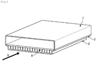
- a plurality of groove portions are formed in one surface of the resin plate 2 according to this embodiment on the side of the metal plate 3, and the groove portions are preferably formed over the entire one surface on the side of the metal plate 3.
- the groove portion functions as a flow path 8 for a refrigerant by being in close contact with the surface of the metal plate 2.
- top portions of the plurality of groove portions are set to have the same height, and some or all top portions are in contact with the surface of the metal plate 2.
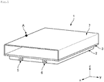
- An inlet pipe connection port 5 and an outlet pipe connection port 6 are provided at an inlet portion and an outlet portion of the flowpath (that is, end portions of the flow path) .
- a manifold portion is optionally provided in the flow path.
- a reinforcing rib is preferably formed on the surface of the resin plate 2 according to this embodiment opposite to the surface on the side of the metal plate 3, and more preferably formed over the entire surface.
- the metal plate 3 constituting the cooling plate 1 performs two functions: it diffuses heat from a heat generating body such as a lithium ion battery, and transfers the heat to the refrigerant flowing in the resin plate 2. Therefore, the metal species constituting the metal plate 3 have excellent heat conductivity.
- aluminum or copper is used as the metal species constituting the metal plate 3, and specifically, at least one selected from the group consisting of an aluminum member, an aluminum alloy member, a copper member, and a copper alloy member is preferably used to constitute the metal plate.
- the average thickness of the metal plate 3 is, for example, 0.5 mm to 30 mm, and preferably 0.5 mm to 20 mm in consideration of heat conductivity, strength, and lightness.
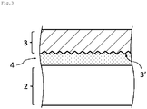
- At least the surface of the adhesion portion of the metal plate 3 to the adhesive layer 4 is preferably degreased. More preferably, at least the surface of the adhesion portion of the metal plate 3 to the adhesive layer 4 has fine unevenness or a hydrophilic group formed therein. It is even more preferable that a hydrophilic group is further formed in the surface having fine unevenness from the viewpoint of little temporal change in adhesion strength at a high temperature and a high humidity, and from the viewpoint of excellent adhesion strength after immersion in the cooling liquid.
- the adhesion strength between the adhesive layer 4 and the metal plate 3 can be increased, and as a result, leakage of the refrigerant can be further suppressed, and it is possible to obtain a cooling plate 1 which is more excellent in reliability of durability and mechanical strength.
- the size (depth, pore size, inter-pore distance, and the like) of the fine unevenness formed in the metal surface is not particularly limited, but ten-point average roughness Rz measured according to JIS B 0601: 2001 is, for example, 1 ⁇ m or greater, preferably 1 ⁇ m to 1 mm, and more preferably 3 ⁇ m to 100 ⁇ m.
- the method of forming the fine unevenness having the above-described ten-point average roughness Rz in the metal surface of the metal plate 3 is not particularly limited, and examples thereof include a method of immersing a metal member in an aqueous solution of an inorganic base such as sodium hydroxide and/or an aqueous solution of an inorganic acid such as hydrochloric acid or nitric acid; a method of treating a metal member by an anodizing method; a method of forming unevenness in a surface of a metal member by pressing a die punch having unevenness produced by mechanical cutting such as diamond abrasive grain grinding or blasting against the surface of the metal member, or a method of producing unevenness in a surface of a metal member by sand blasting, knurling, or laser processing; and a method of immersing a metal member in an aqueous solution of one or more selected from hydrated hydrazine, ammonia, and a water-soluble amine compound as disclosed in International Public
- hydrophilic group covering the metal surface examples include a hydroxyl group and a silanol group.
- a hydrophilic group such as a hydroxyl group can be introduced to the metal surface by, for example, implementing a plasma surface modification technology developed by appropriately combining OPENAIR (trade name) and PLASMAPLUS (trade name) technologies developed by Plasmatreat GmbH.
- a silanol group can be introduced to the metal surface by, for example, an itro treatment (silicic acid flame treatment) described in Japanese Patent No. 3557194 , and thus introduction of the functional groups can be achieved.
- fine unevenness may be formed in the metal surface by the above method, and then a plasma or itro treatment may be further performed thereon.
- the cooling plate 1 is formed by superposing the metal plate 3 over the surface of the resin plate 2 where the groove portions are formed, and bonding them together through an adhesive layer.
- the adhesive is applied to an adhesion surface on the side of the resin plate 2 and/or an adhesion surface on the side of the metal plate 3, and then the adhesion surfaces are adhered to each other.
- the adhesion conditions vary depending on the type of the adhesive used, but for example, the bonding can be performed at a temperature of room temperature to 150°C for 0.1 minutes to 7 days.
- the adhesion may be performed under pressure. In a case where the adhesion is performed under pressure, the pressure is, for example, about 0.01 to 1 MPa.
- At least outer peripheral end portions of the resin plate 2 and the metal plate 3 are preferably riveted or screwed to each other, in addition to the bonding of the resin plate 2 to the metal plate 3 through the adhesive layer 4 as described above.
- the resin plate 2 and the metal plate are firmly bonded and mechanically fastened to each other in two stages, it is possible to more effectively suppress the leakage of the refrigerant flowing in the resin plate 2.
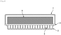
- a battery structure includes a battery block in which two or more prismatic, cylindrical, or pouch battery cells 11 are disposed with flat surfaces set in an upright posture so as to be in close contact with each other or to be adjacent to each other at regular intervals, the cooling plate 1 according to this embodiment, and a case 7 which houses the battery block, and the battery block is disposed so as to be in contact with the metal plate 3 of the cooling plate 1.
- the cooling plate 1 is used to cool a battery block in which two or more prismatic, cylindrical, or pouch battery cells are disposed with flat surfaces set in an upright posture so as to be in close contact with each other or to be adjacent to each other at regular intervals.
- the battery block according to this embodiment preferably includes a plurality of battery cells 11 (see Fig. 5 ), a pair of side plates (not shown) which are fixed in a state in which the plurality of battery cells 11 are arranged in a predetermined direction, and a pair of end plates (not shown) which are disposed at both ends in the arrangement direction of the battery cells 11.
- the cooling plate 1 preferably extends in the arrangement direction of the plurality of battery cells 11.
- one or more battery blocks are covered by, for example, a box-like or U-shaped metal case to provide water-proof, dust-proof, and impact-proof functions.
- the battery cell 11 is, for example, a lithium ion secondary battery.
- a power generation unit (not shown) is housed in a battery can formed of a metal member such as aluminum. A nonaqueous electrolytic solution is injected, and the battery is sealed.
- a spacer 12 fixed to the metal plate 3 may or may not be interposed between the battery cells 11. That is, the spacer 12 (cooling fin) may be formed on the side opposite to the resin plate 2 in the metal plate 3.
- the spacer 12 is not interposed between the battery cells (see (a) of Fig. 5 )
- a void is generated between the adjacent battery cells, and thus air cooling is possible.
- a spacer 12 formed of an insulating member is interposed between the cells (see (b) of Fig. 5 ).
- the spacer 12 is interposed between the battery cells.
- Each spacer 12 has an opening portion into which the battery cell 11 is fitted on both sides thereof in the thickness direction (the arrangement direction of the battery cells), and has a partition wall formed in an intermediate portion thereof.
- the spacer 12 may also have a function as a cooling fin.
- the material of the cooling fin is usually the same as that of the metal plate 3, and specific examples thereof include an aluminum alloy and a copper alloy.
- a heat conductive sheet 10 may be optionally attached to a surface of the cooling fin in contact with the battery cell 11.
- the end plate is formed by, for example, integrally molding an aluminum alloy formed by aluminum die casting or the like, a high-rigidity resin, or a resin and a steel plate.
- the heat conductive sheet 10 is preferably interposed between the cooling plate 1 and a bottom surface of each battery cell 11.
- the numbers of heat conductive sheets 10 and the number of battery cells 11 are the same. That is, the heat conductive sheets 10 and the battery cells 11 are preferably disposed at a ratio of 1:1.
- the insulation resistance may be reduced.
- a structure in which one heat conductive sheet 10 is disposed to cover the whole region of the bottom surfaces of the battery cells may be employed.
- a so-called thermal interface material may be used, and specific examples thereof include a thermal grease, a phase-change material (PCM), a gel, a high heat conductive adhesive, and a thermal tape.
- the cooling plate 1 and each battery cell 11 may be provided with no heat conductive layer interposed therebetween, and may be in direct contact with each other.
- a test piece shown in Fig. 6 was produced by sequentially performing a degreasing treatment of an aluminum alloy, a surface treatment of a resin molded body, and a step of applying and curing an adhesive according to the following methods.
- An aluminum alloy plate (45 mm ⁇ 18 mm ⁇ 2.0 mm) of Alloy No. 6061 defined in JIS H4000 was degreased with a commercially available degreasing agent for an aluminum alloy "NE-6 (manufactured by Meltex Inc.) ". Next, the aluminum alloy plate was sufficiently washed with water, and then dried at 80°C for 20 minutes.
- An adhesion surface of a polyphenylene sulfide resin (manufactured by Tosoh Corporation, inorganic filler content: 45 mass%, referred to as PPS in Table 1) as a resin molded body to the aluminum alloy plate was UV-treated in the usual manner (referred to as UV in Table 1) .
- UV in Table 1 An adhesion surface of a polyphenylene sulfide resin (manufactured by Tosoh Corporation, inorganic filler content: 45 mass%, referred to as PPS in Table 1) as a resin molded body to the aluminum alloy plate was UV-treated in the usual manner (referred to as UV in Table 1) .
- UV in Table 1 An adhesion surface of a polyphenylene sulfide resin (manufactured by Tosoh Corporation, inorganic filler content: 45 mass%, referred to as PPS in Table 1) as a resin molded body to the aluminum alloy plate was UV-treated in the usual manner (referred to as UV in Table 1)
- An epoxy resin adhesive (an adhesive containing epoxy group-containing acrylic modified rubber as a main component, prepared according to Example 3 of Japanese Examined Patent Publication No. S60-26427 (a viscosity measured using a B type viscometer under conditions of 25°C and 0.2 rpm; 120 Pa ⁇ s)) was applied to an end region (5 mm ⁇ 10 mm) of the aluminum alloy plate obtained in the degreasing step and the UV-irradiated surface of the resin molded body, respectively, and the aluminum alloy plate and the resin molded body were relatively disposed such that the epoxy resin adhesive layers applied were completely superposed on each other.
- the adhesive layer had an average thickness of 30 ⁇ m.
- test piece in which the aluminum alloy plate and the resin molded body were relatively disposed was allowed to stand at room temperature for 10 minutes under a load of 1 kg, and then heated and cured at 60°C for 4 hours under the same load to obtain a test piece for measuring tensile shear strength shown in Fig. 6 .
- the measurement was performed with a dedicated tool 105 housing the test piece and attached to the tensile tester under conditions of room temperature (23°C), an inter-chuck distance of 60 mm, and a tensile speed of 10 mm/min.
- a breaking load (N) By dividing a breaking load (N) by an area (5 mm ⁇ 10 mm) of a bonding portion between a metal 101 (aluminum alloy plate) and a resin 103 (resin molded body), the adhesion strength between the aluminum alloy plate and the resin molded body was obtained (see Fig. 7 ). As a result, the adhesion strength was 28 MPa.
- a broken surface of the bonding portion was observed with a magnifying glass, and as a result, the failure type was confirmed to be material failure.
- the material failure refers to cohesive failure of a resin, cohesive failure of an adhesive layer, or mixed failure thereof.
- a test piece was produced in the same manner as in Example 1, except that instead of the UV-treated adhesion surface of the polyphenylene sulfide resin (manufactured by Tosoh Corporation, inorganic filler content: 45 mass%) as the resin molded body to the aluminum alloy plate, a surf ace-treated product (water contact angle: 35°) subjected to a plasma treatment (700 W, scanning speed: 5 m/min, a rotary nozzle, referred to as plasma treatment 1 in Table 1) was used in Example 1, and each evaluation was performed.
- the adhesion strength was obtained in the same manner as in Example 1, and as a result, the adhesion strength was 33 MPa. A broken surface of the bonding portion was observed with a magnifying glass, and as a result, the failure type was confirmed to be material failure.
- the adhesive layer had an average thickness of 30 ⁇ m.
- a test piece was produced in the same manner as in Example 1, except that instead of the UV-treated adhesion surface of the polyphenylene sulfide resin (manufactured by Tosoh Corporation, inorganic filler content: 45 mass%) as the resin molded body to the aluminum alloy plate, a surf ace-treated product (water contact angle: 32°) subjected to a plasma treatment (700 W, scanning speed: 15 m/min, a straight nozzle, referred to as plasma treatment 2 in Table 1) was used in Example 1, and each evaluation was performed.
- the adhesion strength was obtained in the same manner as in Example 1, and as a result, the adhesion strength was 32 MPa. A broken surface of the bonding portion was observed with a magnifying glass, and as a result, the failure type was confirmed to be material failure.
- the adhesive layer had an average thickness of 30 ⁇ m.
- Test pieces were produced in the same manner as in Example 1, except that the surface treatment method of the aluminum alloy plate and the surface treatment method of the resin molded body were changed as shown in Table 1, and the types of the resin constituting the resin molded body and the adhesive were changed as shown in Table 1, and each evaluation was performed.
- Example 13 the measurement was performed after the test piece was stored under an environment of 85°C and 85%RH for 1,500 hours.
- the polyphthalamide resin (PPA) and the silicone resin shown in Table 1 are as follows.
- the surface treatment of the aluminum alloy plate shown in Table 1 was performed according to the following procedures.
- An aluminum alloy plate (thickness: 2.0 mm) of Alloy No. 6061 defined in JIS H4000 was cut into a piece having a length of 45 mm and a width of 18 mm.
- the aluminum alloy plate was etched by being immersed and shaken for 80 seconds in an acidic etching agent (sulfuric acid: 8.2 mass%, ferric chloride: 7.8 mass% (Fe 3+ : 2.7 mass%), cupric chloride: 0.4 mass% (Cu 2+ : 0.2 mass%), ion-exchanged water: remainder) (30°C) . Then, ultrasonic cleaning (in water, 1 minute) was performed with running water and dried.
Landscapes
- Chemical & Material Sciences (AREA)
- Chemical Kinetics & Catalysis (AREA)
- Electrochemistry (AREA)
- General Chemical & Material Sciences (AREA)
- Engineering & Computer Science (AREA)
- Manufacturing & Machinery (AREA)
- Physics & Mathematics (AREA)
- Thermal Sciences (AREA)
- Mechanical Engineering (AREA)
- General Engineering & Computer Science (AREA)
- Inorganic Chemistry (AREA)
- Materials Engineering (AREA)
- Laminated Bodies (AREA)
- Secondary Cells (AREA)
- Battery Mounting, Suspending (AREA)
Abstract
Description
- The present invention relates to a cooling plate and a battery structure.
- A battery block is configured by, for example, arranging and fixing a plurality of battery cells to a support member, and electrically connecting positive and negative terminals of each battery cell to each other by a bus bar or the like. A battery module has, for example, a structure including a plurality of the battery blocks, in which the plural battery blocks are vertically laminated or disposed in parallel, and fixed to a base member.
- The battery block and the battery module are mounted for use in, for example, a power source of an electric vehicle, a hybrid vehicle, or the like, and can output a large current. Each battery cell which forms the battery block generates heat during charging and discharging. Accordingly, the battery block may include a cooling device. As an example of the cooling device for a battery block, a structure in which a cooling pipe is directly fixed to each battery cell, or a structure in which a cooling pipe is built in a box-shaped metal cooling plate and the cooling plate is fixed to a battery cell is known (for example, Patent Document 1).
- [Patent Document 1] Japanese Laid-open Patent Publication No.
2009-134901 - In particular, in a large-size and large-weight battery block, the structure in which a cooling pipe is brought into direct contact with each battery cell to perform cooling may have poor resistance to impact, vibration, and the like. In a battery block including a cooling plate having a built-in cooling pipe, each battery cell is cooled through the cooling pipe built in the cooling plate, and thus cooling efficiency is anticipated to deteriorate. Furthermore, since the cooling plate is made of a metal, a problem occurs in that the weight is increased.
- The invention is contrived in view of the above circumstances, and an object of the invention is to provide a cooling plate which can increase cooling efficiency and makes it possible to achieve weight reduction of an entire battery structure.
- According to the invention, a cooling plate and a battery structure are provided as follows.
- [1] A cooling plate including: a resin plate in which a plurality of groove portions are formed; and a metal plate provided over a surface of the resin plate where the groove portions are formed,
in which the resin plate and the metal plate are bonded to each other through an adhesive layer, and
the groove portion of the resin plate forms a flow path for cooling water. - [2] The cooling plate according to [1], in which the adhesive layer is formed of a film adhesive or a liquid adhesive.
- [3] The cooling plate according to [1] or [2], in which a fine uneven structure is formed in a surface of an adhesion portion of the metal plate to the adhesive layer.
- [4] The cooling plate according to any one of [1] to [3], in which a hydrophilic group is formed in a surface of an adhesion portion of the metal plate to the adhesive layer.
- [5] The cooling plate according to any one of [1] to [4], in which a water contact angle of a surface of an adhesion portion of the resin plate to the adhesive layer is in a range of 10° to 80°.
- [6] The cooling plate according to any one of [1] to [5], in which outer peripheral end portions of the resin plate and the metal plate are riveted or screwed to each other.
- [7] The cooling plate according to any one of [1] to [6], in which the metal plate is formed of at least one selected from the group consisting of an aluminum member, an aluminum alloy member, a copper member, and a copper alloy member.
- [8] The cooling plate according to any one of [1] to [7], in which one end portion of the flow path for cooling water formed by the groove portion formed in the resin plate is connected to an inlet pipe, and the other end portion is connected to an outlet pipe.
- [9] The cooling plate according to any one of [1] to [8], in which the cooling plate is provided to cool a battery block in which two or more prismatic, cylindrical, or pouch battery cells are disposed with flat surfaces set in an upright posture so as to be in close contact with each other or to be adjacent to each other at regular intervals.
- [10] A battery structure including: a battery block in which two or more prismatic, cylindrical, or pouch battery cells are disposed with flat surfaces set in an upright posture so as to be in close contact with each other or to be adjacent to each other at regular intervals;
the cooling plate according to any one of [1] to [9]; and
a case which houses the battery block,
in which the battery block is disposed over the metal plate of the cooling plate. - [11] The battery structure according to [10], in which the battery cell is a lithium ion battery.
- According to the invention, it is possible to provide a cooling plate which can increase cooling efficiency and makes it possible to achieve weight reduction of an entire battery structure.
-
-
Fig. 1 is a perspective view schematically showing an example of a structure of a cooling plate according to this embodiment. -
Fig. 2 is a cross-sectional perspective view in the y-z-direction passing through the point A of the cooling plate shown inFig. 1 . -
Fig. 3 is a conceptual view schematically showing an example of an adhesion state between a resin plate and a metal plate according to this embodiment. -
Fig. 4 is a cross-sectional view in whichFig. 2 is viewed from the S-direction. -
Fig. 5 shows cross-sectional views showing examples (a) and (b) of the arrangement of battery cells housed in the case shown inFig. 4 . -
Fig. 6 is a perspective view schematically showing a structure of a test piece for measuring tensile shear strength according to this embodiment. -
Fig. 7 is a cross-sectional view schematically showing a tensile shear strength test method according to this embodiment. - Hereinafter, embodiments of the invention will be described with reference to the drawings. In all the drawings, the same constituent elements are denoted by the same reference numerals, and description thereof will not be repeated. The drawings are schematic drawings showing an example of the invention, and dimension ratios in the drawings are different from the actual dimension ratios. Unless otherwise specified, the symbol "-" between numbers in the sentence represents from ... to.
- A cooling plate 1 according to this embodiment includes a
resin plate 2 in which a plurality of groove portions are formed, and ametal plate 3 provided over a surface of theresin plate 2 where the groove portions are formed. Theresin plate 2 and themetal plate 3 are bonded to each other through anadhesive layer 4, and the groove portion of theresin plate 2 forms aflow path 8 for cooling water. - Since the
entire metal plate 3 is cooled by theflow paths 8 for cooling water formed in theresin plate 2, the cooling efficiency of battery cells in contact with themetal plate 3 can be increased. In addition, since theflow paths 8 for cooling water are formed by thelightweight resin plate 2, the weight of an entire battery structure can be reduced. - As described above, according to the cooling plate 1 according to this embodiment, cooling efficiency can be increased, and weight reduction of an entire battery structure can be achieved.
- Hereinafter, the
adhesive layer 4, theresin plate 2, and themetal plate 3 constituting the cooling plate 1 will be sequentially described, and then an example of a method of forming the cooling plate 1 with the constituent elements will be described. - In a surface where the
resin plate 2 and themetal plate 3 of the cooling plate 1 according to this embodiment are in contact with each other, a layer formed of the resin plate 2 (hereinafter, may be referred to as a resin layer), theadhesive layer 4, and a layer formed of the metal plate 3 (hereinafter, may be referred to as a metal layer) are laminated in this order. - As an adhesive which forms the
adhesive layer 4 according to this embodiment, a known solid or liquid (including a paste form) adhesive can be used. The method of forming an adhesive layer is not particularly limited, and a known method of forming an adhesive layer can be appropriately selected. - A film adhesive is preferable as a solid adhesive from the viewpoint of simplifying the process, and specific examples thereof include an adhesive in which an adhesive is laminated on both sides of a film, such as a known double-sided adhesive tape.
- A solid adhesive is preferably used in a case where it is difficult to uniformly and thinly apply a liquid adhesive, or it is difficult to secure resistance to impact and bending. In addition, the solid adhesive may be preferably used from the viewpoint of reducing coating and drying steps.
- In this embodiment, a known natural or synthetic adhesive can be used without limitation as a liquid adhesive which forms the adhesive layer, and a synthetic adhesive is preferable from the viewpoint of persistence of the adhesive force.
- Synthetic adhesives can be classified into thermoplastic adhesives, heat curable adhesives, and elastomers, and heat curable adhesives are preferable from the viewpoint of adhesion strength. The heat curable adhesive may be a room temperature-reactive adhesive (one component type) or a thermosetting adhesive (two component type).
- In a case where the material of the resin plate is likely to be deformed by heat, a room temperature-reactive adhesive is preferable, and in a case where the material of the resin plate is less likely to be deformed by heat, a thermosetting adhesive is preferable since productivity (adhesion speed and the like) is prioritized.
- Examples of the room temperature-reactive adhesive include cyanoacrylate-based adhesives (one component) and modified silicone resin-based adhesives (moisture curing), and examples of the thermosetting adhesive include epoxy resin-based adhesives, melamine resin-based adhesives, phenolic resin-based adhesives, and urea resin-based adhesives (mainly two components) . Among the adhesives, adhesives containing an acrylic-modified heat curable resin such as an acrylic-modified epoxy resin or an acrylic-modified phenolic resin as a main component are preferably used from the viewpoint of bonding strength and environment resistance. Specific examples of the acrylic-modified heat curable resin include a graft polymer of a heat curable resin and a vinyl polymer, which is obtained by polymerizing an acrylate-based monomer such as an alkyl acrylate or a hydroxyethyl acrylate in the presence of a heat curable resin such as an epoxy resin or a phenolic resin. The type of the adhesive is optionally determined by those skilled in the art depending on the conditions such as what type of cooling plate is to be formed and what type of material is to be used for forming the cooling plate.
- In this embodiment, the average thickness of the adhesive layer is, for example, 0.5 to 5,000 µm, preferably 1.0 to 2,000 µm, and more preferably 10 to 1, 000 µm. In a case where the average thickness is equal to or greater than the lower limit, the resin layer and the metal layer exhibit sufficient adhesion strength, and in a case where the average thickness is equal to or less than the upper limit, the residual strain amount generated during the curing reaction can be minimized.
- The cooling plate 1 according to this embodiment may include a primer layer between the resin layer and the adhesive layer and between the adhesive layer and the metal layer. The primer layer is not particularly limited, and is usually made of a resin material containing a resin component constituting the resin layer. The resin material for a primer layer is not particularly limited, and a known material can be used. Specific examples thereof include polyolefin-based primers, epoxy-based primers, and urethane-based primers. The primers may be used in combination of two or more types thereof, including a multilayer mode.
- The
resin plate 2 according to this embodiment is preferably a molded body of a thermoplastic resin composition. The thermoplastic resin composition contains a thermoplastic resin as a resin component, and may further optionally contain a filler. - The thermoplastic resin is not particularly limited, and examples thereof include polyolefin-based resins, polar group-containing polyolefin-based resins, polymethacrylic resins such as a polymethylmethacrylate resin, polyacrylic resins such as a polymethylacrylate resin, polystyrene resins, polyvinyl alcohol-polyvinyl chloride copolymer resins, polyvinyl acetal resins, polyvinyl butyral resins, polyvinyl formal resins, polymethyl pentene resins, maleic anhydride-styrene copolymer resins, polycarbonate resins, polyphenylene ether resins, aromatic polyether ketones such as polyether ether ketone resins and polyether ketone resins, polyester-based resins, polyamide-based resins, polyamide imide resins, polyimide resins, polyether imide resins, styrene-based elastomers, polyolefin-based elastomers, polyurethane-based elastomers, polyester-based elastomers, polyamide-based elastomers, ionomers, amino polyacrylamide resins, isobutylene-maleic anhydride copolymers, ABS, ACS, AES, AS, ASA, MBS, ethylene-vinyl chloride copolymers, ethylene-vinyl acetate copolymers, ethylene-vinyl acetate-vinyl chloride graft polymers, ethylene-vinyl alcohol copolymers, chlorinated polyvinyl chloride resins, chlorinated polyethylene resins, chlorinated polypropylene resins, carboxyl vinyl polymers, ketone resins, amorphous copolyester resins, norbornene resins, fluoroplastics, polytetrafluoroethylene resins, fluorinated ethylene polypropylene resins, PFA, polychlorofluoroethylene resins,ethylene-tetrafluoroethylene copolymers, polyvinylidene fluoride resins, polyvinyl fluoride resins, polyarylate resins, thermoplastic polyimide resins, polyvinylidene chloride resins, polyvinyl chloride resins, polyvinyl acetate resins, polysulfone resins, poly-para-methylstyrene resins, polyallylamine resins, polyvinyl ether resins, polyphenylene oxide resins, polyphenylene sulfide (PPS) resins, polymethylpentene resins, oligoester acrylates, xylene resins, maleic acid resins, polyhydroxybutyrate resins, polysulfone resins, polylactic acid resins, polyglutamic acid resins, polycaprolactone resins, polyether sulfone resins, polyacrylonitrile resins, and styrene-acrylonitrile copolymer resins. The thermoplastic resins may be used alone or in combination of two or more types thereof.
- Among these, as the thermoplastic resin, one or two or more thermoplastic resins selected from polyolefin-based resins, polyester-based resins, polyamide-based resins, fluororesins, polyarylene ether-based resins, and polyarylene sulfide-based resins are preferably used from the viewpoint of more efficiently obtaining the effect of improving the adhesion strength between the
resin plate 2 and theadhesive layer 4 and/or between themetal plate 3 and theadhesive layer 4. - In the thermoplastic resin composition according to this embodiment, an optional component and a filler can be used in combination from the viewpoint of improving mechanical characteristics of the
resin plate 2 and adjusting a difference in coefficient of linear expansion. As the filler, for example, one or two or more can be selected from the group consisting of glass fiber, carbon fiber, carbon particles, clay, talc, silica, mineral, and cellulose fiber. Among these, one or two or more selected from glass fiber, carbon fiber, talc, and mineral are preferable. A heat dissipating filler typified by alumina, forsterite, mica, alumina nitride, boron nitride, zinc oxide, magnesium oxide, or the like can also be used. The shape of the fillers is not particularly limited, and may be any one of a fibrous shape, a particle shape, a plate shape, and the like. However, as will be described later, in a case where the surface of themetal plate 3 has fine unevenness (also referred to as a fine uneven structure), a filler having a size large enough to enter the recess is preferably used. - In a case where the thermoplastic resin composition contains a filler, the content of the filler is preferably 1 part by mass to 100 parts by mass, more preferably 5 parts by mass to 90 parts by mass, and particularly preferably 10 parts by mass to 80 parts by mass with respect to 100 parts by mass of the thermoplastic resin.
- A heat curable resin composition can also be used as the
resin plate 2 according to this embodiment. The heat curable resin composition is a resin composition containing a heat curable resin. Examples of the heat curable resin include a phenolic resin, an epoxy resin, an unsaturated polyester resin, a diallyl phthalate resin, a melamine resin, an oxetane resin, a maleimide resin, an urea resin, a polyurethane resin, a silicone resin, a resin having a benzoxazine ring, and a cyanate ester resin. These may be used alone or in combination of two or more types thereof. - Among these, a heat curable resin composition containing one or more selected from the group consisting of a phenolic resin, an epoxy resin, and an unsaturated polyester resin is preferably used from the viewpoint of heat resistance, workability, mechanical characteristics, adhesion, rust resistance, and the like. The content of the heat curable resin in the heat curable resin composition is preferably 15 parts by mass to 60 parts by mass, and more preferably 25 parts by mass to 50 parts by mass, assuming that a total amount of the resin composition is 100 parts by mass. The residual component is, for example, a filler, and as the filler, for example, the above-described filler can be used.
- A known method can be used without limitation as a method of molding the
resin plate 2, and examples thereof include injection molding, extrusion molding, hot press molding, compression molding, transfer molding, cast molding, laser welding molding, reaction injection molding (RIM molding), liquid injection molding (LIM molding), and spray molding. Among these, an injection molding method is preferable as the method of manufacturing theresin plate 2 from the viewpoint of productivity and quality stability. - The water contact angle of the surface of the adhesion portion of the
resin plate 2 according to this embodiment to the adhesive layer 4 (the surface bonded to themetal plate 3 through the adhesive layer) is, for example, 10° to 80°, preferably 20° to 65°, more preferably 20° to 50°, and even more preferably 20° to 40° or 25° to 60°. In a case where the water contact angle of the surface of the bonding portion satisfies the above range, the adhesion strength between theresin plate 2 and themetal plate 3 can be increased. - A known method can be used to impart a water contact angle within a specific range to the surface of the
resin plate 2, and examples thereof include a UV treatment, a corona treatment, an ozone treatment, and a plasma treatment. - A plurality of groove portions are formed in one surface of the
resin plate 2 according to this embodiment on the side of themetal plate 3, and the groove portions are preferably formed over the entire one surface on the side of themetal plate 3. The groove portion functions as aflow path 8 for a refrigerant by being in close contact with the surface of themetal plate 2. Usually, top portions of the plurality of groove portions are set to have the same height, and some or all top portions are in contact with the surface of themetal plate 2. An inletpipe connection port 5 and an outletpipe connection port 6 are provided at an inlet portion and an outlet portion of the flowpath (that is, end portions of the flow path) . A manifold portion is optionally provided in the flow path. - A reinforcing rib is preferably formed on the surface of the
resin plate 2 according to this embodiment opposite to the surface on the side of themetal plate 3, and more preferably formed over the entire surface. By forming the reinforcing rib, the structural strength of the resin plate against external stress is increased, and by setting a high rib height, a sufficient space is formed between the resin plate and the contact plane, and a heat insulation effect can be improved in some cases. - The
metal plate 3 constituting the cooling plate 1 according to this embodiment performs two functions: it diffuses heat from a heat generating body such as a lithium ion battery, and transfers the heat to the refrigerant flowing in theresin plate 2. Therefore, the metal species constituting themetal plate 3 have excellent heat conductivity. From such a viewpoint, aluminum or copper is used as the metal species constituting themetal plate 3, and specifically, at least one selected from the group consisting of an aluminum member, an aluminum alloy member, a copper member, and a copper alloy member is preferably used to constitute the metal plate. The average thickness of themetal plate 3 is, for example, 0.5 mm to 30 mm, and preferably 0.5 mm to 20 mm in consideration of heat conductivity, strength, and lightness. - At least the surface of the adhesion portion of the
metal plate 3 to theadhesive layer 4 is preferably degreased. More preferably, at least the surface of the adhesion portion of themetal plate 3 to theadhesive layer 4 has fine unevenness or a hydrophilic group formed therein. It is even more preferable that a hydrophilic group is further formed in the surface having fine unevenness from the viewpoint of little temporal change in adhesion strength at a high temperature and a high humidity, and from the viewpoint of excellent adhesion strength after immersion in the cooling liquid. - In this manner, the adhesion strength between the
adhesive layer 4 and themetal plate 3 can be increased, and as a result, leakage of the refrigerant can be further suppressed, and it is possible to obtain a cooling plate 1 which is more excellent in reliability of durability and mechanical strength. - In the preferred embodiment (first embodiment) of the invention, the size (depth, pore size, inter-pore distance, and the like) of the fine unevenness formed in the metal surface is not particularly limited, but ten-point average roughness Rz measured according to JIS B 0601: 2001 is, for example, 1 µm or greater, preferably 1 µm to 1 mm, and more preferably 3 µm to 100 µm.
- The method of forming the fine unevenness having the above-described ten-point average roughness Rz in the metal surface of the
metal plate 3 is not particularly limited, and examples thereof include a method of immersing a metal member in an aqueous solution of an inorganic base such as sodium hydroxide and/or an aqueous solution of an inorganic acid such as hydrochloric acid or nitric acid; a method of treating a metal member by an anodizing method; a method of forming unevenness in a surface of a metal member by pressing a die punch having unevenness produced by mechanical cutting such as diamond abrasive grain grinding or blasting against the surface of the metal member, or a method of producing unevenness in a surface of a metal member by sand blasting, knurling, or laser processing; and a method of immersing a metal member in an aqueous solution of one or more selected from hydrated hydrazine, ammonia, and a water-soluble amine compound as disclosed in International Publication No.WO2009/31632 - In particular, in a case where an immersion method is employed among the above-described methods, fine unevenness over the
metal plate 3 is formed not only over the contact surface with theresin plate 2, but also over the whole surface of themetal plate 3, and the effects of the invention are not impaired by the above embodiment. - In another preferred embodiment (second embodiment) of the invention, specific examples of the hydrophilic group covering the metal surface include a hydroxyl group and a silanol group. A hydrophilic group such as a hydroxyl group can be introduced to the metal surface by, for example, implementing a plasma surface modification technology developed by appropriately combining OPENAIR (trade name) and PLASMAPLUS (trade name) technologies developed by Plasmatreat GmbH. In addition, a silanol group can be introduced to the metal surface by, for example, an itro treatment (silicic acid flame treatment) described in Japanese Patent No.
3557194 - The cooling plate 1 according to this embodiment is formed by superposing the
metal plate 3 over the surface of theresin plate 2 where the groove portions are formed, and bonding them together through an adhesive layer. Specifically, for example, the adhesive is applied to an adhesion surface on the side of theresin plate 2 and/or an adhesion surface on the side of themetal plate 3, and then the adhesion surfaces are adhered to each other. The adhesion conditions vary depending on the type of the adhesive used, but for example, the bonding can be performed at a temperature of room temperature to 150°C for 0.1 minutes to 7 days. The adhesion may be performed under pressure. In a case where the adhesion is performed under pressure, the pressure is, for example, about 0.01 to 1 MPa. - In the cooling plate 1 according to this embodiment, at least outer peripheral end portions of the
resin plate 2 and themetal plate 3 are preferably riveted or screwed to each other, in addition to the bonding of theresin plate 2 to themetal plate 3 through theadhesive layer 4 as described above. As described above, in a case where theresin plate 2 and the metal plate are firmly bonded and mechanically fastened to each other in two stages, it is possible to more effectively suppress the leakage of the refrigerant flowing in theresin plate 2. - Hereinafter, an embodiment of a battery block and a battery structure according to this embodiment will be described.
- A battery structure according to this embodiment includes a battery block in which two or more prismatic, cylindrical, or
pouch battery cells 11 are disposed with flat surfaces set in an upright posture so as to be in close contact with each other or to be adjacent to each other at regular intervals, the cooling plate 1 according to this embodiment, and acase 7 which houses the battery block, and the battery block is disposed so as to be in contact with themetal plate 3 of the cooling plate 1. - That is, the cooling plate 1 according to this embodiment is used to cool a battery block in which two or more prismatic, cylindrical, or pouch battery cells are disposed with flat surfaces set in an upright posture so as to be in close contact with each other or to be adjacent to each other at regular intervals.
- The battery block according to this embodiment preferably includes a plurality of battery cells 11 (see
Fig. 5 ), a pair of side plates (not shown) which are fixed in a state in which the plurality ofbattery cells 11 are arranged in a predetermined direction, and a pair of end plates (not shown) which are disposed at both ends in the arrangement direction of thebattery cells 11. In addition, the cooling plate 1 preferably extends in the arrangement direction of the plurality ofbattery cells 11. Preferably, one or more battery blocks are covered by, for example, a box-like or U-shaped metal case to provide water-proof, dust-proof, and impact-proof functions. - The
battery cell 11 is, for example, a lithium ion secondary battery. In eachbattery cell 11, for example, a power generation unit (not shown) is housed in a battery can formed of a metal member such as aluminum. A nonaqueous electrolytic solution is injected, and the battery is sealed. - A
spacer 12 fixed to themetal plate 3 may or may not be interposed between thebattery cells 11. That is, the spacer 12 (cooling fin) may be formed on the side opposite to theresin plate 2 in themetal plate 3. In a case where thespacer 12 is not interposed between the battery cells (see (a) ofFig. 5 ), a void is generated between the adjacent battery cells, and thus air cooling is possible. Usually, aspacer 12 formed of an insulating member is interposed between the cells (see (b) ofFig. 5 ). In particular, in a case where pouch battery cells are used, thespacer 12 is interposed between the battery cells. Eachspacer 12 has an opening portion into which thebattery cell 11 is fitted on both sides thereof in the thickness direction (the arrangement direction of the battery cells), and has a partition wall formed in an intermediate portion thereof. - In the battery structure according to this embodiment, the
spacer 12 may also have a function as a cooling fin. The material of the cooling fin is usually the same as that of themetal plate 3, and specific examples thereof include an aluminum alloy and a copper alloy. A heatconductive sheet 10 may be optionally attached to a surface of the cooling fin in contact with thebattery cell 11. The end plate is formed by, for example, integrally molding an aluminum alloy formed by aluminum die casting or the like, a high-rigidity resin, or a resin and a steel plate. - The heat
conductive sheet 10 is preferably interposed between the cooling plate 1 and a bottom surface of eachbattery cell 11. Usually, the numbers of heatconductive sheets 10 and the number ofbattery cells 11 are the same. That is, the heatconductive sheets 10 and thebattery cells 11 are preferably disposed at a ratio of 1:1. By virtue of the above structure, heat conduction between eachbattery cell 11 and the cooling plate 1 can be improved even in a case where the position of a lower surface of eachbattery cell 11 in the height direction (Z-direction) is uneven. - However, in a case where the heat
conductive sheet 10 is a strip member given at a ratio of 1:1 with thebattery cell 11, the insulation resistance may be reduced. Regarding this, in a case where no spacers or cooling fins are erected on the surface of the metal plate, a structure in which one heatconductive sheet 10 is disposed to cover the whole region of the bottom surfaces of the battery cells may be employed. In a case where all the lower surfaces of thebattery cells 11 are substantially flat, only one heat conductive sheet can be used. Instead of the heatconductive sheet 10, a so-called thermal interface material (TIM) may be used, and specific examples thereof include a thermal grease, a phase-change material (PCM), a gel, a high heat conductive adhesive, and a thermal tape. That is, a structure in which between the cooling plate 1 and eachbattery cell 11, an insulating heat conductive layer allowing heat conduction between both the members is interposed is preferable. The cooling plate 1 and eachbattery cell 11 may be provided with no heat conductive layer interposed therebetween, and may be in direct contact with each other. - Although the embodiments of the invention have been described above, these are merely an example of the invention, and include various configurations other than those described above.
- Hereinafter, embodiments of the invention will be described with examples, but this embodiment is not limited thereto.
- A test piece shown in
Fig. 6 was produced by sequentially performing a degreasing treatment of an aluminum alloy, a surface treatment of a resin molded body, and a step of applying and curing an adhesive according to the following methods. - An aluminum alloy plate (45 mm × 18 mm × 2.0 mm) of Alloy No. 6061 defined in JIS H4000 was degreased with a commercially available degreasing agent for an aluminum alloy "NE-6 (manufactured by Meltex Inc.) ". Next, the aluminum alloy plate was sufficiently washed with water, and then dried at 80°C for 20 minutes.
- An adhesion surface of a polyphenylene sulfide resin (manufactured by Tosoh Corporation, inorganic filler content: 45 mass%, referred to as PPS in Table 1) as a resin molded body to the aluminum alloy plate was UV-treated in the usual manner (referred to as UV in Table 1) . Usually, the UV irradiation was performed under conditions of room temperature, 254 nm wavelength, and 5 minutes. The water contact angle of the UV-treated surface of the resin molded body was 33°. Here, in this example, the water contact angle was measured according to JIS R3257.
- An epoxy resin adhesive (an adhesive containing epoxy group-containing acrylic modified rubber as a main component, prepared according to Example 3 of Japanese Examined Patent Publication No.
S60-26427 - Here, the adhesive layer had an average thickness of 30 µm.
- The test piece in which the aluminum alloy plate and the resin molded body were relatively disposed was allowed to stand at room temperature for 10 minutes under a load of 1 kg, and then heated and cured at 60°C for 4 hours under the same load to obtain a test piece for measuring tensile shear strength shown in
Fig. 6 . - Using a tensile tester "Model 1323 (manufactured by Aikoh Engineering Co., Ltd.)", the measurement was performed with a
dedicated tool 105 housing the test piece and attached to the tensile tester under conditions of room temperature (23°C), an inter-chuck distance of 60 mm, and a tensile speed of 10 mm/min. By dividing a breaking load (N) by an area (5 mm × 10 mm) of a bonding portion between a metal 101 (aluminum alloy plate) and a resin 103 (resin molded body), the adhesion strength between the aluminum alloy plate and the resin molded body was obtained (seeFig. 7 ). As a result, the adhesion strength was 28 MPa. A broken surface of the bonding portion was observed with a magnifying glass, and as a result, the failure type was confirmed to be material failure. Specifically, the material failure refers to cohesive failure of a resin, cohesive failure of an adhesive layer, or mixed failure thereof. - A test piece was produced in the same manner as in Example 1, except that instead of the UV-treated adhesion surface of the polyphenylene sulfide resin (manufactured by Tosoh Corporation, inorganic filler content: 45 mass%) as the resin molded body to the aluminum alloy plate, a surf ace-treated product (water contact angle: 35°) subjected to a plasma treatment (700 W, scanning speed: 5 m/min, a rotary nozzle, referred to as plasma treatment 1 in Table 1) was used in Example 1, and each evaluation was performed. The adhesion strength was obtained in the same manner as in Example 1, and as a result, the adhesion strength was 33 MPa. A broken surface of the bonding portion was observed with a magnifying glass, and as a result, the failure type was confirmed to be material failure.
- Here, the adhesive layer had an average thickness of 30 µm.
- A test piece was produced in the same manner as in Example 1, except that instead of the UV-treated adhesion surface of the polyphenylene sulfide resin (manufactured by Tosoh Corporation, inorganic filler content: 45 mass%) as the resin molded body to the aluminum alloy plate, a surf ace-treated product (water contact angle: 32°) subjected to a plasma treatment (700 W, scanning speed: 15 m/min, a straight nozzle, referred to as
plasma treatment 2 in Table 1) was used in Example 1, and each evaluation was performed. The adhesion strength was obtained in the same manner as in Example 1, and as a result, the adhesion strength was 32 MPa. A broken surface of the bonding portion was observed with a magnifying glass, and as a result, the failure type was confirmed to be material failure. - Here, the adhesive layer had an average thickness of 30 µm.
- Test pieces were produced in the same manner as in Example 1, except that the surface treatment method of the aluminum alloy plate and the surface treatment method of the resin molded body were changed as shown in Table 1, and the types of the resin constituting the resin molded body and the adhesive were changed as shown in Table 1, and each evaluation was performed.
- In Examples 11 and 12, the measurement was performed after the test piece was immersed in Super Long Life Coolant KQ301-34002 (44% ethylene glycol-containing aqueous solution) manufactured by Nissan Motor Co., Ltd. at 85°C for 168 hours.
- In Examples 13 and 14, the measurement was performed after the test piece was stored under an environment of 85°C and 85%RH for 1,500 hours.
- The polyphthalamide resin (PPA) and the silicone resin shown in Table 1 are as follows.
- PPA (manufactured by Mitsui Chemicals, Inc., product name: ARLEN A335)
- Silicone Resin (manufactured by ThreeBond Holdings Co., Ltd., product name: TB1226)
- The surface treatment of the aluminum alloy plate shown in Table 1 was performed according to the following procedures.
- An aluminum alloy plate (thickness: 2.0 mm) of Alloy No. 6061 defined in JIS H4000 was cut into a piece having a length of 45 mm and a width of 18 mm. The aluminum alloy plate was etched by being immersed and shaken for 80 seconds in an acidic etching agent (sulfuric acid: 8.2 mass%, ferric chloride: 7.8 mass% (Fe3+: 2.7 mass%), cupric chloride: 0.4 mass% (Cu2+: 0.2 mass%), ion-exchanged water: remainder) (30°C) . Then, ultrasonic cleaning (in water, 1 minute) was performed with running water and dried.
[Table 1] Aluminum Alloy Plate Resin Adhesive Adhesion Strength [MPa] Failure Type Surface Treatment Fine Uneven Structure Type Surface Treatment Water Contact Angle Example 1 degreasing none PPS UV 33° epoxy resin 28 cohesive failure Example 2 degreasing none PPS plasma 1 35° epoxy resin 33 cohesive failure Example 3 degreasing none PPS plasma 2 32° epoxy resin 32 cohesive failure Example 4 degreasing none PPA UV 24° epoxy resin 32 cohesive failure Example 5 degreasing none PPA plasma 1 27° epoxy resin 27 cohesive failure Example 6 degreasing none PPA plasma 2 27° epoxy resin 27 cohesive failure Example 7 degreasing none PPA UV 24° silicone resin 2 cohesive failure Example 8 degreasing none PPS none 84° epoxy resin 2 interfacial failure Example 9 degreasing none PPA none 82° epoxy resin 3 interfacial failure Example 10 surface treatment present PPA UV 24° epoxy resin 31 cohesive failure Example 11 degreasing none PPA UV 24° epoxy resin 13 cohesive failure + partial interfacial failure Example 12 surface treatment present PPA UV 24° epoxy resin 33 cohesive failure + partial interfacial failure Example 13 degreasing none PPA UV 24° epoxy resin 20 cohesive failure + partial interfacial failure Example 14 surface treatment present PPA UV 24° epoxy resin 41 cohesive failure - This application claims priority to Japanese Patent Application No.
2018-147073 filed on August 3, 2018 -
- 1:
- cooling plate
- 2:
- resin plate
- 3:
- metal plate
- 3':
- fine uneven structure
- 4:
- adhesive layer
- 5:
- inlet pipe connection port
- 6:
- outlet pipe connection port
- 7:
- case
- 8:
- flow path
- 9:
- arranged battery cells
- 10:
- heat conductive sheet
- 11:
- battery cell
- 12:
- spacer (cooling fin)
- 101:
- metal
- 102:
- adhesive layer
- 103:
- resin
- 105:
- tool
Claims (11)
- A cooling plate comprising:a resin plate in which a plurality of groove portions are formed; anda metal plate provided over a surface of the resin plate where the groove portions are formed,wherein the resin plate and the metal plate are bonded to each other through an adhesive layer, andthe groove portion of the resin plate forms a flow path for cooling water.
- The cooling plate according to claim 1,
wherein the adhesive layer is formed of a film adhesive or a liquid adhesive. - The cooling plate according to claim 1 or 2,
wherein a fine uneven structure is formed in a surface of an adhesion portion of the metal plate to the adhesive layer. - The cooling plate according to any one of claims 1 to 3,
wherein a hydrophilic group is formed in a surface of an adhesion portion of the metal plate to the adhesive layer. - The cooling plate according to any one of claims 1 to 4,
wherein a water contact angle of a surface of an adhesion portion of the resin plate to the adhesive layer is in a range of 10° to 80°. - The cooling plate according to any one of claims 1 to 5,
wherein outer peripheral end portions of the resin plate and the metal plate are riveted or screwed to each other. - The cooling plate according to any one of claims 1 to 6,
wherein the metal plate is formed of at least one selected from the group consisting of an aluminum member, an aluminum alloy member, a copper member, and a copper alloy member. - The cooling plate according to any one of claims 1 to 7,
wherein one end portion of the flow path for cooling water formed by the groove portion formed in the resin plate is connected to an inlet pipe, and the other end portion is connected to an outlet pipe. - The cooling plate according to any one of claims 1 to 8,
wherein the cooling plate is provided to cool a battery block in which two or more prismatic, cylindrical, or pouch battery cells are disposed with flat surfaces set in an upright posture so as to be in close contact with each other or to be adjacent to each other at regular intervals. - A battery structure comprising:a battery block in which two or more prismatic, cylindrical, or pouch battery cells are disposed with flat surfaces set in an upright posture so as to be in close contact with each other or to be adjacent to each other at regular intervals;the cooling plate according to any one of claims 1 to 9; anda case which houses the battery block,wherein the battery block is disposed over the metal plate of the cooling plate.
- The battery structure according to claim 10,
wherein the battery cell is a lithium ion battery.
Applications Claiming Priority (2)
| Application Number | Priority Date | Filing Date | Title |
|---|---|---|---|
| JP2018147073 | 2018-08-03 | ||
| PCT/JP2019/030363 WO2020027299A1 (en) | 2018-08-03 | 2019-08-01 | Cooling plate and battery structure |
Publications (2)
| Publication Number | Publication Date |
|---|---|
| EP3832786A1 true EP3832786A1 (en) | 2021-06-09 |
| EP3832786A4 EP3832786A4 (en) | 2022-04-20 |
Family
ID=69231242
Family Applications (1)
| Application Number | Title | Priority Date | Filing Date |
|---|---|---|---|
| EP19843601.6A Withdrawn EP3832786A4 (en) | 2018-08-03 | 2019-08-01 | Cooling plate and battery structure |
Country Status (6)
| Country | Link |
|---|---|
| US (1) | US20210249710A1 (en) |
| EP (1) | EP3832786A4 (en) |
| JP (1) | JP7097975B2 (en) |
| KR (1) | KR20210025653A (en) |
| CN (1) | CN112514141A (en) |
| WO (1) | WO2020027299A1 (en) |
Cited By (2)
| Publication number | Priority date | Publication date | Assignee | Title |
|---|---|---|---|---|
| WO2023001806A1 (en) | 2021-07-19 | 2023-01-26 | Zephyros, Inc. | Acrylate adhesive for contact with liquid coolant |
| EP3989331A4 (en) * | 2019-06-21 | 2023-07-19 | Mitsui Chemicals, Inc. | Cooling device and structure |
Families Citing this family (22)
| Publication number | Priority date | Publication date | Assignee | Title |
|---|---|---|---|---|
| MX2022004816A (en) | 2019-10-24 | 2022-05-16 | Invista Textiles Uk Ltd | Polyamide compositions and articles made therefrom. |
| KR102945046B1 (en) * | 2020-04-28 | 2026-03-26 | 주식회사 엘지에너지솔루션 | Battery module and battery pack including the same |
| KR102941260B1 (en) | 2020-04-29 | 2026-03-18 | 주식회사 엘지에너지솔루션 | Battery module and battery pack including the same |
| KR102864265B1 (en) * | 2020-09-04 | 2025-09-26 | 주식회사 엘지에너지솔루션 | Battery Pack Assembly System and Battery Pack Assembly Method Using the Same |
| CN114464912A (en) * | 2020-11-10 | 2022-05-10 | 英威达纺织(英国)有限公司 | Battery cooling assembly and manufacturing method thereof |
| KR20220075045A (en) * | 2020-11-26 | 2022-06-07 | 주식회사 엘지에너지솔루션 | Battery module and battery pack including the same and vehicle including the same |
| US20240120595A1 (en) * | 2021-03-01 | 2024-04-11 | Nippon Steel Corporation | Battery unit |
| US11745295B2 (en) * | 2021-03-26 | 2023-09-05 | Sogefi Air & Cooling Usa, Inc. | Manufacture of heat exchangers via hybrid welding |
| JP7337115B2 (en) | 2021-04-05 | 2023-09-01 | プライムプラネットエナジー&ソリューションズ株式会社 | storage module |
| KR102800926B1 (en) * | 2021-05-26 | 2025-04-24 | 주식회사 엘지에너지솔루션 | A battery pack with a structure that reduces the temperature of venting gas and blocks the emission of sparks into outside of pack case |
| KR20220170339A (en) | 2021-06-22 | 2022-12-29 | 주식회사 엘지에너지솔루션 | Battery module and battery pack including the same |
| DE102021120654A1 (en) * | 2021-08-09 | 2023-02-09 | Elringklinger Ag | Battery module and module housing and method for manufacturing the module housing |
| CN113904049A (en) * | 2021-10-21 | 2022-01-07 | 明尼苏达矿业制造特殊材料(上海)有限公司 | Packaging sheet for new energy automobile power battery, new energy automobile power battery assembly and disassembly method thereof |
| JP7619299B2 (en) * | 2022-02-14 | 2025-01-22 | トヨタ自動車株式会社 | Battery pack case |
| CN115011100B (en) * | 2022-07-05 | 2024-02-06 | 安徽新富新能源科技股份有限公司 | Novel cold plate |
| KR20240028583A (en) * | 2022-08-24 | 2024-03-05 | 주식회사 엘지에너지솔루션 | Battery module and battery pack including the same |
| JP2024090936A (en) * | 2022-12-23 | 2024-07-04 | 株式会社レゾナック | Heat exchanger and method for manufacturing the same |
| JP2025008528A (en) * | 2023-07-05 | 2025-01-20 | 住友理工株式会社 | Cooling Heat Exchanger |
| JP2025012983A (en) * | 2023-07-14 | 2025-01-24 | 住友理工株式会社 | Cooling Heat Exchanger |
| EP4528205A1 (en) * | 2023-09-22 | 2025-03-26 | Röchling Automotive SE | Heat exchanger device and method for manufacturing a heat exchanger device |
| WO2025100535A1 (en) * | 2023-11-09 | 2025-05-15 | 日本製鉄株式会社 | Cooling structure and battery unit |
| CN119965406B (en) * | 2025-02-14 | 2025-08-12 | 山东先捷动力有限公司 | A battery heat dissipation device and method for lithium iron phosphate battery energy storage |
Family Cites Families (20)
| Publication number | Priority date | Publication date | Assignee | Title |
|---|---|---|---|---|
| JPS51126871A (en) | 1975-04-26 | 1976-11-05 | Citizen Watch Co Ltd | The structure of movement fixation for a clock |
| JPS6026427B2 (en) | 1978-08-02 | 1985-06-24 | 三井東圧化学株式会社 | Thermosetting resin composition with improved toughness |
| JP2001256933A (en) | 2000-03-10 | 2001-09-21 | Mitsubishi Chemicals Corp | Battery and battery pack |
| US6441128B1 (en) * | 2000-08-28 | 2002-08-27 | Bernard D. Bauman | ECTFE surfaces modified by fluoro-oxidation and a process therefor |
| JP5108891B2 (en) | 2007-09-05 | 2012-12-26 | 大成プラス株式会社 | Method for producing metal resin composite |
| JP5183172B2 (en) | 2007-11-28 | 2013-04-17 | 三洋電機株式会社 | Battery system |
| JP2010248454A (en) | 2009-04-20 | 2010-11-04 | Mitsui Chemicals Inc | Plasma treatment apparatus and plasma treatment method |
| JP5791718B2 (en) * | 2011-07-29 | 2015-10-07 | 株式会社Uacj | Current collector, electrode structure, non-aqueous electrolyte battery, power storage component |
| DE102012012663A1 (en) * | 2012-06-23 | 2013-12-24 | Volkswagen Aktiengesellschaft | Housing for carrying and cooling lithium ion battery pack for drive of electric vehicle, has separation body arranged between operating device and trough, where body and trough limit intermediate space to guide coolant in flow-proof design |
| DE102012217367A1 (en) * | 2012-09-26 | 2014-03-27 | Robert Bosch Gmbh | Battery module of battery system mounted in e.g. hybrid vehicle, has clamping element that is provided for clamping battery cells against each other, and cooler that is integrated in clamping element provided with inner/outer elements |
| FR3003938A1 (en) * | 2013-03-29 | 2014-10-03 | Valeo Systemes Thermiques | THERMAL EXCHANGE PLATE FOR THERMAL BATTERY MANAGEMENT AND METHOD OF MANUFACTURING THE SAME. |
| JP2014216298A (en) * | 2013-04-30 | 2014-11-17 | 日立オートモティブシステムズ株式会社 | Battery module |
| JP6165665B2 (en) | 2013-05-30 | 2017-07-19 | 信越化学工業株式会社 | Substrate cleaning method |
| DE102014219812A1 (en) | 2014-09-30 | 2016-03-31 | Robert Bosch Gmbh | Cooling plate for an electrical energy storage |
| JP6721410B2 (en) | 2015-05-21 | 2020-07-15 | 株式会社巴川製紙所 | Protective film, film laminate, and polarizing plate |
| JP6519365B2 (en) * | 2015-07-07 | 2019-05-29 | 富士通株式会社 | Bonding body, method of manufacturing bonding body, cooling system, and information processing apparatus |
| DE102016103411A1 (en) * | 2016-02-26 | 2017-08-31 | Dr. Ing. H.C. F. Porsche Aktiengesellschaft | Battery device for an at least partially electrically powered vehicle |
| KR102381004B1 (en) | 2016-09-23 | 2022-03-30 | 니폰 제온 가부시키가이샤 | Multilayer films, polarizers and liquid crystal displays |
| DE102016222550B4 (en) * | 2016-11-16 | 2020-03-05 | Volkswagen Aktiengesellschaft | Floor arrangement for a temperature-controlled battery housing |
| JP6815899B2 (en) | 2017-03-02 | 2021-01-20 | 東京都公立大学法人 | Output statement generator, output statement generator and output statement generator |
-
2019
- 2019-08-01 CN CN201980050780.1A patent/CN112514141A/en not_active Withdrawn
- 2019-08-01 KR KR1020217003303A patent/KR20210025653A/en not_active Abandoned
- 2019-08-01 WO PCT/JP2019/030363 patent/WO2020027299A1/en not_active Ceased
- 2019-08-01 EP EP19843601.6A patent/EP3832786A4/en not_active Withdrawn
- 2019-08-01 JP JP2020534755A patent/JP7097975B2/en not_active Expired - Fee Related
- 2019-08-01 US US17/265,321 patent/US20210249710A1/en not_active Abandoned
Cited By (2)
| Publication number | Priority date | Publication date | Assignee | Title |
|---|---|---|---|---|
| EP3989331A4 (en) * | 2019-06-21 | 2023-07-19 | Mitsui Chemicals, Inc. | Cooling device and structure |
| WO2023001806A1 (en) | 2021-07-19 | 2023-01-26 | Zephyros, Inc. | Acrylate adhesive for contact with liquid coolant |
Also Published As
| Publication number | Publication date |
|---|---|
| WO2020027299A1 (en) | 2020-02-06 |
| JPWO2020027299A1 (en) | 2021-04-30 |
| KR20210025653A (en) | 2021-03-09 |
| US20210249710A1 (en) | 2021-08-12 |
| JP7097975B2 (en) | 2022-07-08 |
| EP3832786A4 (en) | 2022-04-20 |
| CN112514141A (en) | 2021-03-16 |
Similar Documents
| Publication | Publication Date | Title |
|---|---|---|
| EP3832786A1 (en) | Cooling plate and battery structure | |
| JP7405225B2 (en) | Battery packaging material, manufacturing method thereof, and battery | |
| JP7212762B2 (en) | Cooling unit, cooling device, battery structure and electric vehicle | |
| EP3989331A1 (en) | Cooling device and structure | |
| US7245493B2 (en) | Cooler for cooling electric part | |
| JP6019812B2 (en) | Packaging materials for electrochemical cells | |
| CN100530762C (en) | Battery, tab for battery and method for manufacturing the tab | |
| JP5633157B2 (en) | Lithium-ion battery packaging material | |
| JP2011216390A (en) | Packaging material for lithium ion battery | |
| WO2015083657A1 (en) | Battery-packaging material | |
| JP7772262B2 (en) | Exterior material for power storage device, manufacturing method thereof, and power storage device | |
| CN112297539A (en) | Packaging materials and batteries for batteries | |
| JP2016186872A (en) | Battery packaging materials | |
| JP6900648B2 (en) | Battery packaging materials, their manufacturing methods, and batteries | |
| CN108886115B (en) | Battery packaging material, method for producing same, and battery | |
| US20230051560A1 (en) | Housing, structural body, and method of manufacturing housing | |
| JPWO2017188396A1 (en) | Packaging material for battery, method for manufacturing the same, battery and method for manufacturing the same | |
| JP2012238454A (en) | Electrode terminal for secondary battery | |
| CN222146361U (en) | Cooling plates, cooling plate assemblies, battery devices and electrical equipment | |
| JP2019129236A (en) | Cooling apparatus | |
| JP7186575B2 (en) | Cooling system and battery structure | |
| CN114725574B (en) | Cooling assembly for power battery and power battery module safety device | |
| US20120208059A1 (en) | Method for producing an energy storage device for a vehicle | |
| JP7740403B2 (en) | Exterior material for power storage device, manufacturing method thereof, and power storage device | |
| JP2015046405A (en) | Sheath material for lithium ion batteries |
Legal Events
| Date | Code | Title | Description |
|---|---|---|---|
| STAA | Information on the status of an ep patent application or granted ep patent |
Free format text: STATUS: THE INTERNATIONAL PUBLICATION HAS BEEN MADE |
|
| PUAI | Public reference made under article 153(3) epc to a published international application that has entered the european phase |
Free format text: ORIGINAL CODE: 0009012 |
|
| STAA | Information on the status of an ep patent application or granted ep patent |
Free format text: STATUS: REQUEST FOR EXAMINATION WAS MADE |
|
| 17P | Request for examination filed |
Effective date: 20210204 |
|
| AK | Designated contracting states |
Kind code of ref document: A1 Designated state(s): AL AT BE BG CH CY CZ DE DK EE ES FI FR GB GR HR HU IE IS IT LI LT LU LV MC MK MT NL NO PL PT RO RS SE SI SK SM TR |
|
| DAV | Request for validation of the european patent (deleted) | ||
| DAX | Request for extension of the european patent (deleted) | ||
| A4 | Supplementary search report drawn up and despatched |
Effective date: 20220323 |
|
| RIC1 | Information provided on ipc code assigned before grant |
Ipc: F28F 21/06 20060101ALI20220318BHEP Ipc: F28F 13/18 20060101ALI20220318BHEP Ipc: H05K 7/20 20060101ALI20220318BHEP Ipc: H01M 10/6556 20140101ALI20220318BHEP Ipc: H01M 10/647 20140101ALI20220318BHEP Ipc: H01M 10/643 20140101ALI20220318BHEP Ipc: H01M 10/625 20140101ALI20220318BHEP Ipc: H01M 10/613 20140101ALI20220318BHEP Ipc: H01M 10/6568 20140101AFI20220318BHEP |
|
| RAP3 | Party data changed (applicant data changed or rights of an application transferred) |
Owner name: MITSUI CHEMICALS, INC. |
|
| STAA | Information on the status of an ep patent application or granted ep patent |
Free format text: STATUS: THE APPLICATION HAS BEEN WITHDRAWN |
|
| 18W | Application withdrawn |
Effective date: 20231026 |