EP3832686A1 - Dual parallel moveable electrical contacts/relays - Google Patents
Dual parallel moveable electrical contacts/relays Download PDFInfo
- Publication number
- EP3832686A1 EP3832686A1 EP20211520.0A EP20211520A EP3832686A1 EP 3832686 A1 EP3832686 A1 EP 3832686A1 EP 20211520 A EP20211520 A EP 20211520A EP 3832686 A1 EP3832686 A1 EP 3832686A1
- Authority
- EP
- European Patent Office
- Prior art keywords
- contact
- moveable
- static
- static contact
- contacts
- Prior art date
- Legal status (The legal status is an assumption and is not a legal conclusion. Google has not performed a legal analysis and makes no representation as to the accuracy of the status listed.)
- Withdrawn
Links
- 230000009977 dual effect Effects 0.000 title description 3
- 230000003068 static effect Effects 0.000 claims abstract description 89
- 239000000463 material Substances 0.000 claims description 22
- 238000000034 method Methods 0.000 claims description 19
- BQCADISMDOOEFD-UHFFFAOYSA-N Silver Chemical compound [Ag] BQCADISMDOOEFD-UHFFFAOYSA-N 0.000 description 1
- 239000000956 alloy Substances 0.000 description 1
- 229910045601 alloy Inorganic materials 0.000 description 1
- 238000007796 conventional method Methods 0.000 description 1
- 230000003628 erosive effect Effects 0.000 description 1
- 238000010438 heat treatment Methods 0.000 description 1
- 238000012986 modification Methods 0.000 description 1
- 230000004048 modification Effects 0.000 description 1
- 229910052709 silver Inorganic materials 0.000 description 1
- 239000004332 silver Substances 0.000 description 1
Images


Classifications
-
- H—ELECTRICITY
- H01—ELECTRIC ELEMENTS
- H01H—ELECTRIC SWITCHES; RELAYS; SELECTORS; EMERGENCY PROTECTIVE DEVICES
- H01H50/00—Details of electromagnetic relays
- H01H50/54—Contact arrangements
- H01H50/541—Auxiliary contact devices
-
- H—ELECTRICITY
- H01—ELECTRIC ELEMENTS
- H01H—ELECTRIC SWITCHES; RELAYS; SELECTORS; EMERGENCY PROTECTIVE DEVICES
- H01H1/00—Contacts
- H01H1/12—Contacts characterised by the manner in which co-operating contacts engage
- H01H1/14—Contacts characterised by the manner in which co-operating contacts engage by abutting
- H01H1/20—Bridging contacts
- H01H1/2025—Bridging contacts comprising two-parallel bridges
-
- H—ELECTRICITY
- H01—ELECTRIC ELEMENTS
- H01H—ELECTRIC SWITCHES; RELAYS; SELECTORS; EMERGENCY PROTECTIVE DEVICES
- H01H3/00—Mechanisms for operating contacts
- H01H3/22—Power arrangements internal to the switch for operating the driving mechanism
- H01H3/28—Power arrangements internal to the switch for operating the driving mechanism using electromagnet
-
- H—ELECTRICITY
- H01—ELECTRIC ELEMENTS
- H01H—ELECTRIC SWITCHES; RELAYS; SELECTORS; EMERGENCY PROTECTIVE DEVICES
- H01H3/00—Mechanisms for operating contacts
- H01H3/32—Driving mechanisms, i.e. for transmitting driving force to the contacts
- H01H3/38—Driving mechanisms, i.e. for transmitting driving force to the contacts using spring or other flexible shaft coupling
-
- H—ELECTRICITY
- H01—ELECTRIC ELEMENTS
- H01H—ELECTRIC SWITCHES; RELAYS; SELECTORS; EMERGENCY PROTECTIVE DEVICES
- H01H50/00—Details of electromagnetic relays
- H01H50/54—Contact arrangements
- H01H50/546—Contact arrangements for contactors having bridging contacts
-
- H—ELECTRICITY
- H01—ELECTRIC ELEMENTS
- H01H—ELECTRIC SWITCHES; RELAYS; SELECTORS; EMERGENCY PROTECTIVE DEVICES
- H01H1/00—Contacts
- H01H1/12—Contacts characterised by the manner in which co-operating contacts engage
- H01H1/14—Contacts characterised by the manner in which co-operating contacts engage by abutting
- H01H1/20—Bridging contacts
-
- H—ELECTRICITY
- H01—ELECTRIC ELEMENTS
- H01H—ELECTRIC SWITCHES; RELAYS; SELECTORS; EMERGENCY PROTECTIVE DEVICES
- H01H1/00—Contacts
- H01H1/12—Contacts characterised by the manner in which co-operating contacts engage
- H01H1/14—Contacts characterised by the manner in which co-operating contacts engage by abutting
- H01H1/22—Contacts characterised by the manner in which co-operating contacts engage by abutting with rigid pivoted member carrying the moving contact
- H01H1/221—Contacts characterised by the manner in which co-operating contacts engage by abutting with rigid pivoted member carrying the moving contact and a contact pressure spring acting between the pivoted member and a supporting member
- H01H1/226—Contacts characterised by the manner in which co-operating contacts engage by abutting with rigid pivoted member carrying the moving contact and a contact pressure spring acting between the pivoted member and a supporting member having a plurality of parallel contact bars
-
- H—ELECTRICITY
- H01—ELECTRIC ELEMENTS
- H01H—ELECTRIC SWITCHES; RELAYS; SELECTORS; EMERGENCY PROTECTIVE DEVICES
- H01H3/00—Mechanisms for operating contacts
- H01H3/001—Means for preventing or breaking contact-welding
- H01H2003/002—Means for preventing or breaking contact-welding with lockout, e.g. two contact pairs in series
-
- H—ELECTRICITY
- H01—ELECTRIC ELEMENTS
- H01H—ELECTRIC SWITCHES; RELAYS; SELECTORS; EMERGENCY PROTECTIVE DEVICES
- H01H2201/00—Contacts
- H01H2201/022—Material
- H01H2201/024—Material precious
-
- H—ELECTRICITY
- H01—ELECTRIC ELEMENTS
- H01H—ELECTRIC SWITCHES; RELAYS; SELECTORS; EMERGENCY PROTECTIVE DEVICES
- H01H2225/00—Switch site location
- H01H2225/008—Two different sites for one circuit, e.g. for safety
-
- H—ELECTRICITY
- H01—ELECTRIC ELEMENTS
- H01H—ELECTRIC SWITCHES; RELAYS; SELECTORS; EMERGENCY PROTECTIVE DEVICES
- H01H2225/00—Switch site location
- H01H2225/018—Consecutive operations
-
- H—ELECTRICITY
- H01—ELECTRIC ELEMENTS
- H01H—ELECTRIC SWITCHES; RELAYS; SELECTORS; EMERGENCY PROTECTIVE DEVICES
- H01H9/00—Details of switching devices, not covered by groups H01H1/00 - H01H7/00
- H01H9/30—Means for extinguishing or preventing arc between current-carrying parts
- H01H9/38—Auxiliary contacts on to which the arc is transferred from the main contacts
-
- H—ELECTRICITY
- H01—ELECTRIC ELEMENTS
- H01H—ELECTRIC SWITCHES; RELAYS; SELECTORS; EMERGENCY PROTECTIVE DEVICES
- H01H9/00—Details of switching devices, not covered by groups H01H1/00 - H01H7/00
- H01H9/30—Means for extinguishing or preventing arc between current-carrying parts
- H01H9/40—Multiple main contacts for the purpose of dividing the current through, or potential drop along, the arc
Definitions
- the present disclosure relates to switching devices, and more particularly to electrical contactors or relays.
- the electrical contact functions as the material surface for the closing arc (while closing the electrical circuit), for current carrying (while the circuit is closed), and for opening (breaking the current flow when opening the circuit).
- the material properties for such electrical contacts that provide good arc resistance are traditionally in conflict with the material properties that provide low contact resistance (low voltage drop). Electrical contact arc erosion contributes to increased voltage drop and increased heating due to current flow.
- a mechanical switching system includes a first moveable contact operatively configured to selectively contact a first static contact.
- a second moveable contact is electrically connected in parallel with the first moveable contact and is operatively configured to selectively connect a second static contact that is electrically connected in parallel with the first static contact.
- the first and second moveable contacts are mechanically connected to each other to move the mechanical switching system between a closed circuit position defined by the second movable being in contact with the second static contact, and an open circuit position defined by both the first movable contact being disconnected from the first static contact and the second movable contact being disconnected from the second static contact.
- the first moveable contact contacts the first static contact before the second moveable contact contacts the second static contact as the mechanical switching system is moved from the open circuit position to the closed circuit position.
- the first moveable contact disconnects from the first static contact after the second moveable contact disconnects from the second static contact as the mechanical switching system is moved from the closed circuit position into the open circuit position.
- An actuator can be mechanically connected to the first and second moveable contacts, wherein in the open circuit position, the first moveable contact is separated from the first static contact by a first gap that is smaller than a second gap separating the second moveable contact from the second static contact in the open circuit position.
- a first spring can mechanically connect between the first moveable contact and the actuator, wherein the first spring is configured to accommodate continued stroke of the actuator moving the second moveable contact after the first moveable contact contacts the first static contact.
- a second spring can mechanically connect between the second moveable contact and the actuator, wherein the second spring is configured to accommodate continued stroke of the actuator moving after the second moveable contact contacts the second static contact.
- the first and second static contacts and the first and second moveable contacts can all be on one side of the actuator.
- the actuator can be a commandable actuator configured to actuate between the open and closed circuit positions based on input.
- the actuator can include a solenoid motor.
- the first moveable contact can include two separate electrical contact points, and the first static contact can include two respective contact points aligned for contacting the two separate electrical contact points of the first moveable contact.
- the second moveable contact can include two separate electrical contact points, and the second static contact can include two respective contact points aligned for contacting the two separate electrical contact points of the second moveable contact.
- the first moveable contact and the first static contact can include respective contact points of a first contactor material that is different from a second contactor material included in respective contact points of the second moveable contact and the second static contact.
- the first contactor material can have a higher arc resistance than that of the second contactor material.
- the second contactor material can provide a lower voltage drop than that of the first contactor material.
- the contacts are configured such that when the mechanical switching system is in the closed circuit position a first resistance across the first contacts is more than a second resistance across the second contacts.
- a method includes closing a circuit by first contacting a first static contact with a first moveable contact, wherein an electrical arc forms between the first static contact and the first moveable contact before they contact one another.
- the method includes then contacting a second static contact with a second moveable contact, wherein no electrical arc forms between the second static contact and the second moveable contact, the first contacts and the second contacts being electrically in parallel when the circuit is closed.
- the method can include flowing more current through the closed circuit through the second moveable contact and the second static contact than through the first moveable contact and the first static contact.
- the method can include opening the circuit by first separating the second moveable contact from the second static contact wherein no electrical arc forms between the second static contact and the second moveable contact; and then separating the first moveable contact from the first static contact, wherein an electrical arc forms between the first static contact and the first moveable contact after they separate from one another.
- the method can include conducting current from the first moveable contact to the first static contact in parallel with current conducted from the second moveable contact to the second static contact after closing the circuit and before opening the circuit.
- Fig. 1 a partial view of an embodiment of a system in accordance with the disclosure is shown in Fig. 1 and is designated generally by reference character 100.
- FIGs. 2-6 Other embodiments of systems in accordance with the disclosure, or aspects thereof, are provided in Figs. 2-6 , as will be described.
- the systems and methods described herein can be used to for switching power with improved performance relative to traditional techniques.
- Those skilled in the art will readily appreciate that while disclosed below in the context of contacts and contactors, relays can also be used without departing from the scope of the invention as defined by the claims.
- the system 100 includes a mechanical switching device 102 (e.g., a relay or contactor) having a first moveable contact 104 operatively connected to selectively contact a first static contact 106.
- a second moveable contact 108 is operatively connected to selectively contact a second static contact 110 that is electrically connected in parallel to the circuit 112 with the first static contact 106, as indicate by the circuit lines 114 in Fig. 1 .
- the first and second moveable contacts 104, 108 are mechanically connected to each other to move back and forth between a closed circuit position, shown in Fig. 5 , and an open circuit position shown in Fig. 2 .
- an actuator 116 is mechanically connected to the first and second moveable contacts 104, 108 by a mechanical element 122.
- the first moveable contact 104 In the open circuit position, shown in Figs. 1 and 2 , the first moveable contact 104 is separated from the first static contact 106 by a first gap G1 that is smaller than a second gap G2 separating the second moveable contact 108 from the second static contact 110 in the open circuit position (i.e. G1 ⁇ G2).
- a first spring 118 or other resilient member mechanically connects between the first moveable contact 104 and the actuator 116.
- the first spring 118 is configured to accommodate continued stroke of the actuator 116 moving the second moveable contact 108 after the first moveable contact 104 contacts (electrically connects) the first static contact 106 (while the system 100 moves from the state shown in Fig. 4 to the state shown in Fig. 5 ).
- a second spring 120 mechanically connects between the second moveable contact 108 and the actuator 116.
- the second spring is configured to accommodate continued stroke of the actuator 116 moving after the second moveable contact 108 contacts (electrically connects) the second static contact 110.
- the first and second static contacts 106, 110 and the first and second moveable contacts 104, 108 can all be on one side of the actuator 116 e.g., connected to the actuator 116 by a mechanical element 122 shown partially in Fig.
- the actuator 116 can be a commandable actuator configured to actuate between the open and closed circuit positions based on input, e.g. the actuator 116 can include a solenoid motor connected to a controller 124 to open and close the circuit 112 as needed.
- the first moveable contact 104 includes two separate electrical contact points 126
- the first static contact 106 includes two respective contact points 128 aligned for contacting the two separate electrical contact points 126.
- the second moveable contact 108 includes two separate electrical contact points 130.
- the second static contact 110 includes two respective contact points 132 aligned for contacting the two separate electrical contact points 130.
- the contact points 126 and 128 are of a first contactor material and the contact points 130, 132 are of a second contactor material.
- the first contactor material has a higher arc resistance than that of the second contactor material.
- the second contactor material such as a high silver content alloy relative to the first contactor material, provides a lower voltage drop than that of the first contactor material.
- a method includes closing a circuit (e.g. circuit 112 of Fig. 1 ) starting from an open circuit position as shown in Fig. 2 by first contacting a first static contact 106 with a first moveable contact 104. Electrical arcs 134 forms between the first static contact 106 and the first moveable contact 104 as they contact one another as shown in Fig. 3 . After the first contacts 104, 106 are closed, the second movable contact 108 contacts the second static contact 110. In Fig. 4 , electrical current flows between the first static contact 106 and the first moveable contact 104. Then when the second contacts 108, 110 contact each other there is no arc because of negligible voltage drop across the second parallel contacts 108, 110, and the system 100 is in the fully closed circuit position shown in Fig. 5 .
- a circuit e.g. circuit 112 of Fig. 1
- the method can include opening the circuit 112 of Fig. 1 , (going again through Figs. 2-5 but in reverse order, starting in the closed circuit position of Fig. 5 ) by first separating the second moveable contact 108 from the second static contact 110 wherein no electrical arc forms between the second static contact 110 and the second moveable contact 108 as shown in Fig. 4 .
- the method then includes separating the first moveable contact 104 from the first static contact 106, wherein an electrical arc 134 forms between the first static contact 106 and the first moveable contact 104 after they separate from one another, as shown in Fig. 3 , and after continuing to separate the first contacts, 106, the system returns to the fully circuit open position shown in Fig. 2 .
- System 200 has a first moveable contact 204 and a first static contact 206 with respective single contact points 226 and 228, and a second moveable contact 208 second static contact 210 with respective single contact points 230 and 232.
- the contacts 204, 206, 208, 210 are electrically connected in parallel as indicated by circuit lines 214, and can be mechanically connected to an actuator in the same matter described above with reference to Fig. 1 .
Landscapes
- Physics & Mathematics (AREA)
- Electromagnetism (AREA)
- Arc-Extinguishing Devices That Are Switches (AREA)
- Relay Circuits (AREA)
Abstract
Description
- The present disclosure relates to switching devices, and more particularly to electrical contactors or relays.
- In traditional switching devices, the electrical contact functions as the material surface for the closing arc (while closing the electrical circuit), for current carrying (while the circuit is closed), and for opening (breaking the current flow when opening the circuit). The material properties for such electrical contacts that provide good arc resistance are traditionally in conflict with the material properties that provide low contact resistance (low voltage drop). Electrical contact arc erosion contributes to increased voltage drop and increased heating due to current flow.
- The conventional techniques have been considered satisfactory for their intended purpose. However, there is an ever present need for improved systems and methods for electrical contactors/relays. This disclosure provides a solution for this need.
- A mechanical switching system includes a first moveable contact operatively configured to selectively contact a first static contact. A second moveable contact is electrically connected in parallel with the first moveable contact and is operatively configured to selectively connect a second static contact that is electrically connected in parallel with the first static contact. The first and second moveable contacts are mechanically connected to each other to move the mechanical switching system between a closed circuit position defined by the second movable being in contact with the second static contact, and an open circuit position defined by both the first movable contact being disconnected from the first static contact and the second movable contact being disconnected from the second static contact. The first moveable contact contacts the first static contact before the second moveable contact contacts the second static contact as the mechanical switching system is moved from the open circuit position to the closed circuit position. The first moveable contact disconnects from the first static contact after the second moveable contact disconnects from the second static contact as the mechanical switching system is moved from the closed circuit position into the open circuit position.
- An actuator can be mechanically connected to the first and second moveable contacts, wherein in the open circuit position, the first moveable contact is separated from the first static contact by a first gap that is smaller than a second gap separating the second moveable contact from the second static contact in the open circuit position. A first spring can mechanically connect between the first moveable contact and the actuator, wherein the first spring is configured to accommodate continued stroke of the actuator moving the second moveable contact after the first moveable contact contacts the first static contact. A second spring can mechanically connect between the second moveable contact and the actuator, wherein the second spring is configured to accommodate continued stroke of the actuator moving after the second moveable contact contacts the second static contact. The first and second static contacts and the first and second moveable contacts can all be on one side of the actuator. The actuator can be a commandable actuator configured to actuate between the open and closed circuit positions based on input. The actuator can include a solenoid motor.
- The first moveable contact can include two separate electrical contact points, and the first static contact can include two respective contact points aligned for contacting the two separate electrical contact points of the first moveable contact. The second moveable contact can include two separate electrical contact points, and the second static contact can include two respective contact points aligned for contacting the two separate electrical contact points of the second moveable contact.
- The first moveable contact and the first static contact can include respective contact points of a first contactor material that is different from a second contactor material included in respective contact points of the second moveable contact and the second static contact. The first contactor material can have a higher arc resistance than that of the second contactor material. The second contactor material can provide a lower voltage drop than that of the first contactor material. The contacts are configured such that when the mechanical switching system is in the closed circuit position a first resistance across the first contacts is more than a second resistance across the second contacts.
- A method includes closing a circuit by first contacting a first static contact with a first moveable contact, wherein an electrical arc forms between the first static contact and the first moveable contact before they contact one another. The method includes then contacting a second static contact with a second moveable contact, wherein no electrical arc forms between the second static contact and the second moveable contact, the first contacts and the second contacts being electrically in parallel when the circuit is closed.
- The method can include flowing more current through the closed circuit through the second moveable contact and the second static contact than through the first moveable contact and the first static contact. The method can include opening the circuit by first separating the second moveable contact from the second static contact wherein no electrical arc forms between the second static contact and the second moveable contact; and then separating the first moveable contact from the first static contact, wherein an electrical arc forms between the first static contact and the first moveable contact after they separate from one another. The method can include conducting current from the first moveable contact to the first static contact in parallel with current conducted from the second moveable contact to the second static contact after closing the circuit and before opening the circuit.
- These and other features of the systems and methods of the subject disclosure will become more readily apparent to those skilled in the art from the following detailed description of the preferred embodiments taken in conjunction with the drawings.
- So that those skilled in the art to which the subject disclosure appertains will readily understand how to make and use the devices and methods of the subject disclosure without undue experimentation, preferred embodiments thereof will be described in detail herein below with reference to certain figures, wherein:
-
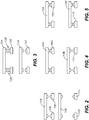
Fig. 1 is a schematic side elevation view of an embodiment of a system constructed in accordance with the present disclosure, showing the actuator and electrically parallel contact connections; -
Figs. 2-5 are schematic side elevations views of a portion of the system ofFig. 1 , showing the open circuit position, electrical arc during opening/closing, during closing/opening with the first contacts closed and the second contacts open, and in the closed circuit position, respectively; and -
Fig. 6 is a schematic side elevation view of a system similar to that ofFig. 1 but with single parallel contacts rather than dual parallel contacts. - Reference will now be made to the drawings wherein like reference numerals identify similar structural features or aspects of the subject disclosure. For purposes of explanation and illustration, and not limitation, a partial view of an embodiment of a system in accordance with the disclosure is shown in
Fig. 1 and is designated generally byreference character 100. Other embodiments of systems in accordance with the disclosure, or aspects thereof, are provided inFigs. 2-6 , as will be described. The systems and methods described herein can be used to for switching power with improved performance relative to traditional techniques. Those skilled in the art will readily appreciate that while disclosed below in the context of contacts and contactors, relays can also be used without departing from the scope of the invention as defined by the claims. - The
system 100 includes a mechanical switching device 102 (e.g., a relay or contactor) having a firstmoveable contact 104 operatively connected to selectively contact a firststatic contact 106. A secondmoveable contact 108 is operatively connected to selectively contact a secondstatic contact 110 that is electrically connected in parallel to thecircuit 112 with the firststatic contact 106, as indicate by thecircuit lines 114 inFig. 1 . The first and secondmoveable contacts Fig. 5 , and an open circuit position shown inFig. 2 . - With continued reference to
Fig. 1 , anactuator 116 is mechanically connected to the first and secondmoveable contacts mechanical element 122. In the open circuit position, shown inFigs. 1 and2 , the firstmoveable contact 104 is separated from the firststatic contact 106 by a first gap G1 that is smaller than a second gap G2 separating the secondmoveable contact 108 from the secondstatic contact 110 in the open circuit position (i.e. G1<G2). Afirst spring 118 or other resilient member mechanically connects between the firstmoveable contact 104 and theactuator 116. Thefirst spring 118 is configured to accommodate continued stroke of theactuator 116 moving the secondmoveable contact 108 after the firstmoveable contact 104 contacts (electrically connects) the first static contact 106 (while thesystem 100 moves from the state shown inFig. 4 to the state shown inFig. 5 ). Asecond spring 120 mechanically connects between the secondmoveable contact 108 and theactuator 116. The second spring is configured to accommodate continued stroke of theactuator 116 moving after the secondmoveable contact 108 contacts (electrically connects) the secondstatic contact 110. The first and secondstatic contacts moveable contacts actuator 116 e.g., connected to theactuator 116 by amechanical element 122 shown partially inFig. 1 for sake of clarity. Theactuator 116 can be a commandable actuator configured to actuate between the open and closed circuit positions based on input, e.g. theactuator 116 can include a solenoid motor connected to acontroller 124 to open and close thecircuit 112 as needed. - The first
moveable contact 104 includes two separateelectrical contact points 126, and the firststatic contact 106 includes tworespective contact points 128 aligned for contacting the two separateelectrical contact points 126. The secondmoveable contact 108 includes two separateelectrical contact points 130. The secondstatic contact 110 includes tworespective contact points 132 aligned for contacting the two separateelectrical contact points 130. Thecontact points contact points - With reference now to
Figs. 2-5 , a method includes closing a circuit (e.g. circuit 112 ofFig. 1 ) starting from an open circuit position as shown inFig. 2 by first contacting a firststatic contact 106 with a firstmoveable contact 104. Electrical arcs 134 forms between the firststatic contact 106 and the firstmoveable contact 104 as they contact one another as shown inFig. 3 . After thefirst contacts movable contact 108 contacts the secondstatic contact 110. InFig. 4 , electrical current flows between the firststatic contact 106 and the firstmoveable contact 104. Then when thesecond contacts parallel contacts system 100 is in the fully closed circuit position shown inFig. 5 . - The method can include opening the
circuit 112 ofFig. 1 , (going again throughFigs. 2-5 but in reverse order, starting in the closed circuit position ofFig. 5 ) by first separating the secondmoveable contact 108 from the secondstatic contact 110 wherein no electrical arc forms between the secondstatic contact 110 and the secondmoveable contact 108 as shown inFig. 4 . The method then includes separating the firstmoveable contact 104 from the firststatic contact 106, wherein anelectrical arc 134 forms between the firststatic contact 106 and the firstmoveable contact 104 after they separate from one another, as shown inFig. 3 , and after continuing to separate the first contacts, 106, the system returns to the fully circuit open position shown inFig. 2 . Whether opening or closing, there is no electrical arc in the position shown inFig. 4 due to the current flowing through thefirst contacts second contacts circuit 112 and before opening thecircuit 112 ofFig. 1 . - With reference now to
Fig. 6 , thesystem 100 described above has dual parallel contact points 126, 128, 130, 132. However it is also contemplated that single parallel contact points can also be used as inSystem 200.System 200 has a firstmoveable contact 204 and a firststatic contact 206 with respective single contact points 226 and 228, and a secondmoveable contact 208 secondstatic contact 210 with respective single contact points 230 and 232. Thecontacts circuit lines 214, and can be mechanically connected to an actuator in the same matter described above with reference toFig. 1 . - The methods and systems of the present disclosure, as described above and shown in the drawings, provide for contacts/relays with improved arc resistance, voltage drop, and useable life time than in traditional configurations. While the apparatus and methods of the subject disclosure have been shown and described with reference to preferred embodiments, those skilled in the art will readily appreciate that changes and/or modifications may be made thereto without departing from the scope of the invention as defined by the claims.
Claims (15)
- A mechanical switching system comprising:a first moveable contact (104) operatively configured to selectively contact a first static contact (106); anda second moveable (108) contact that is electrically connected in parallel with the first moveable contact and operatively configured to selectively connect a second static contact (110) that is electrically connected in parallel with the first static contact,wherein the first and second moveable contacts are mechanically connected to each other to move the mechanical switching system between a closed circuit position defined by the second movable being in contact with the second static contact, and an open circuit position defined by both the first movable contact being disconnected from the first static contact and the second movable contact being disconnected from the second static contact,wherein the first moveable contact contacts the first static contact before the second moveable contact contacts the second static contact as the mechanical switching system is moved from the open circuit position to the closed circuit position, andwherein the first moveable contact disconnects from the first static contact after the second moveable contact disconnects from the second static contact as the mechanical switching system is moved from the closed circuit position into the open circuit position.
- The system as recited in claim 1, further comprising an actuator (116) mechanically connected to the first and second moveable contacts, wherein in the open circuit position, the first moveable contact is separated from the first static contact by a first gap that is smaller than a second gap separating the second moveable contact from the second static contact in the open circuit position.
- The system as recited in claim 2, wherein a first spring (118) mechanically connects between the first moveable contact and the actuator, wherein the first spring is configured to accommodate continued stroke of the actuator moving the second moveable contact after the first moveable contact contacts the first static contact.
- The system as recited in claim 2 or 3, wherein a second spring (120) mechanically connects between the second moveable contact and the actuator, wherein the second spring is configured to accommodate continued stroke of the actuator moving after the second moveable contact contacts the second static contact.
- The system as recited in claim 2, 3 or 4, wherein the first and second static contacts and the first and second moveable contacts are all on one side of the actuator.
- The system as recited in any of claims 2 to 5, wherein the actuator is a commandable actuator configured to actuate between the open and closed circuit positions based on input, and optionally wherein the actuator includes a solenoid motor.
- The system as recited in any preceding claim, wherein the first moveable contact includes two separate electrical contact points (126), and wherein the first static contact includes two respective contact points (128) aligned for contacting the two separate electrical contact points of the first moveable contact.
- The system as recited in any preceding claim, wherein the second moveable contact includes two separate electrical contact points (130), and wherein the second static contact includes two respective contact points (132) aligned for contacting the two separate electrical contact points of the second moveable contact.
- The system as recited in any preceding claim, wherein the first moveable contact and the first static contact include respective contact points of a first material that is different from a second material included in respective contact points of the second moveable contact and the second static contact, and optionally wherein the first material has a higher arc resistance than that of the second material.
- The system as recited in claim 9, wherein the second material provides a lower voltage drop than that of the first material.
- The system as recited in any preceding claim, wherein the contacts are configured such that when the mechanical switching system is in the closed circuit position a first resistance across the first contacts is more than a second resistance across the second contacts.
- A method comprising:
closing a circuit by:first contacting a first static contact (106) with a first moveable contact (104), wherein an electrical arc forms between the first static contact and the first moveable contact before they contact one another; andthen contacting a second static contact (110) with a second moveable contact (108), wherein no electrical arc forms between the second static contact and the second moveable contact, the first contacts and the second contacts being electrically in parallel when the circuit is closed - The method as recited in claim 12, further comprising flowing more current through the closed circuit through the second moveable contact and the second static contact than through the first moveable contact and the first static contact.
- The method as recited in claim 12 or 13, further comprising opening the circuit by:first separating the second moveable contact from the second static contact wherein no electrical arc forms between the second static contact and the second moveable contact; andthen separating the first moveable contact from the first static contact, wherein an electrical arc forms between the first static contact and the first moveable contact after they separate from one another.
- The method as recited in claim 14, further comprising conducting current from the first moveable contact to the first static contact in parallel with current conducted from the second moveable contact to the second static contact after closing the circuit and before opening the circuit.
Applications Claiming Priority (1)
| Application Number | Priority Date | Filing Date | Title |
|---|---|---|---|
| US16/701,568 US11195671B2 (en) | 2019-12-03 | 2019-12-03 | Dual parallel moveable electrical contacts/relays |
Publications (1)
| Publication Number | Publication Date |
|---|---|
| EP3832686A1 true EP3832686A1 (en) | 2021-06-09 |
Family
ID=73698621
Family Applications (1)
| Application Number | Title | Priority Date | Filing Date |
|---|---|---|---|
| EP20211520.0A Withdrawn EP3832686A1 (en) | 2019-12-03 | 2020-12-03 | Dual parallel moveable electrical contacts/relays |
Country Status (2)
| Country | Link |
|---|---|
| US (2) | US11195671B2 (en) |
| EP (1) | EP3832686A1 (en) |
Cited By (1)
| Publication number | Priority date | Publication date | Assignee | Title |
|---|---|---|---|---|
| WO2023051958A1 (en) * | 2021-09-30 | 2023-04-06 | Eaton Intelligent Power Limited | Electrical switch arrangement for reducing arc energy and erosion in a contact system |
Families Citing this family (4)
| Publication number | Priority date | Publication date | Assignee | Title |
|---|---|---|---|---|
| JP7434769B2 (en) * | 2019-09-13 | 2024-02-21 | オムロン株式会社 | electromagnetic relay |
| US11195671B2 (en) * | 2019-12-03 | 2021-12-07 | Hamilton Sundstrand Corporation | Dual parallel moveable electrical contacts/relays |
| FR3131073A1 (en) * | 2021-12-17 | 2023-06-23 | Safran Electrical & Power | Double contact power contactor |
| EP4700811A1 (en) * | 2024-08-23 | 2026-02-25 | Abb Schweiz Ag | An electric current switch |
Citations (4)
| Publication number | Priority date | Publication date | Assignee | Title |
|---|---|---|---|---|
| US20080073327A1 (en) * | 2006-09-22 | 2008-03-27 | Jeffrey Ramsey Annis | Contactor assembly with arc steering system |
| EP2474989A2 (en) * | 2011-01-06 | 2012-07-11 | Tai-Her Yang | Sequential switching device with surrounding heterogeneous joint points structure |
| WO2017059910A1 (en) * | 2015-10-08 | 2017-04-13 | Abb Schweiz Ag | Switching device |
| WO2018086366A1 (en) * | 2016-11-08 | 2018-05-17 | 仲大卫 | Arcless breaking device of contactor, contactor, and arcless breaking method |
Family Cites Families (6)
| Publication number | Priority date | Publication date | Assignee | Title |
|---|---|---|---|---|
| JP4199951B2 (en) * | 2002-03-06 | 2008-12-24 | アルプス電気株式会社 | By-wire shift lever device for vehicles |
| US6956728B2 (en) | 2003-02-28 | 2005-10-18 | Eaton Corporation | Method and apparatus to control modular asynchronous contactors |
| WO2010035082A2 (en) | 2008-09-25 | 2010-04-01 | Panasonic Electric Works Co., Ltd. | Hybrid relay and control terminal apparatus |
| JP2016192326A (en) | 2015-03-31 | 2016-11-10 | 株式会社日本自動車部品総合研究所 | Relay device and relay system |
| US10134551B2 (en) | 2016-09-21 | 2018-11-20 | Astronics Advanced Electronic Systems Corp. | Galvanically isolated hybrid contactor |
| US11195671B2 (en) * | 2019-12-03 | 2021-12-07 | Hamilton Sundstrand Corporation | Dual parallel moveable electrical contacts/relays |
-
2019
- 2019-12-03 US US16/701,568 patent/US11195671B2/en active Active
-
2020
- 2020-12-03 EP EP20211520.0A patent/EP3832686A1/en not_active Withdrawn
-
2021
- 2021-08-11 US US17/399,180 patent/US11710606B2/en active Active
Patent Citations (5)
| Publication number | Priority date | Publication date | Assignee | Title |
|---|---|---|---|---|
| US20080073327A1 (en) * | 2006-09-22 | 2008-03-27 | Jeffrey Ramsey Annis | Contactor assembly with arc steering system |
| EP2474989A2 (en) * | 2011-01-06 | 2012-07-11 | Tai-Her Yang | Sequential switching device with surrounding heterogeneous joint points structure |
| EP2474989B1 (en) * | 2011-01-06 | 2014-03-19 | Tai-Her Yang | Sequential switching device with surrounding heterogeneous joint points structure |
| WO2017059910A1 (en) * | 2015-10-08 | 2017-04-13 | Abb Schweiz Ag | Switching device |
| WO2018086366A1 (en) * | 2016-11-08 | 2018-05-17 | 仲大卫 | Arcless breaking device of contactor, contactor, and arcless breaking method |
Cited By (1)
| Publication number | Priority date | Publication date | Assignee | Title |
|---|---|---|---|---|
| WO2023051958A1 (en) * | 2021-09-30 | 2023-04-06 | Eaton Intelligent Power Limited | Electrical switch arrangement for reducing arc energy and erosion in a contact system |
Also Published As
| Publication number | Publication date |
|---|---|
| US11710606B2 (en) | 2023-07-25 |
| US20220013307A1 (en) | 2022-01-13 |
| US11195671B2 (en) | 2021-12-07 |
| US20210166890A1 (en) | 2021-06-03 |
Similar Documents
| Publication | Publication Date | Title |
|---|---|---|
| US11710606B2 (en) | Dual parallel moveable electrical contacts/relays | |
| CN109716580B (en) | Battery | |
| US9218918B2 (en) | Single pole switching unit and switchgear device comprising one such unit | |
| CN101728101B (en) | Micro switch | |
| KR100814514B1 (en) | On-load tap changer | |
| EP4465323A1 (en) | Relay | |
| CN105190814B (en) | The electric switchgear of Lorentz force activation | |
| JP6744339B2 (en) | High voltage DC relay | |
| CN102473549A (en) | Gas circuit breaker with reset ohmic contact, and method for resetting and tripping same | |
| US9837232B2 (en) | Electromechanical circuit breaker | |
| CN111613478B (en) | Actuation system for vacuum bottles | |
| US9270069B2 (en) | Angled electrical contactor | |
| JP7599587B2 (en) | Switchgear | |
| EP3984052B1 (en) | Progressively contacting switch and method for operating it | |
| US20250069832A1 (en) | Dual-contact power contactor | |
| EP4465333A1 (en) | Relay | |
| EP4465332A1 (en) | Relay | |
| JP7593302B2 (en) | Circuit Breakers | |
| CN118571673A (en) | Electrical contactor suitable for use in high-power circuits, aircraft comprising a circuit incorporating at least one such electrical contactor | |
| CN119487602A (en) | Fused single point high voltage contactor with quick disconnect | |
| JP6024592B2 (en) | Overcurrent detection device and current interruption device using the same | |
| EP2913834A1 (en) | Contact assembly of switching device and switching device thereof | |
| JPH0896668A (en) | Gas circuit breaker |
Legal Events
| Date | Code | Title | Description |
|---|---|---|---|
| PUAI | Public reference made under article 153(3) epc to a published international application that has entered the european phase |
Free format text: ORIGINAL CODE: 0009012 |
|
| STAA | Information on the status of an ep patent application or granted ep patent |
Free format text: STATUS: THE APPLICATION HAS BEEN PUBLISHED |
|
| AK | Designated contracting states |
Kind code of ref document: A1 Designated state(s): AL AT BE BG CH CY CZ DE DK EE ES FI FR GB GR HR HU IE IS IT LI LT LU LV MC MK MT NL NO PL PT RO RS SE SI SK SM TR |
|
| STAA | Information on the status of an ep patent application or granted ep patent |
Free format text: STATUS: REQUEST FOR EXAMINATION WAS MADE |
|
| 17P | Request for examination filed |
Effective date: 20211209 |
|
| RBV | Designated contracting states (corrected) |
Designated state(s): AL AT BE BG CH CY CZ DE DK EE ES FI FR GB GR HR HU IE IS IT LI LT LU LV MC MK MT NL NO PL PT RO RS SE SI SK SM TR |
|
| STAA | Information on the status of an ep patent application or granted ep patent |
Free format text: STATUS: EXAMINATION IS IN PROGRESS |
|
| 17Q | First examination report despatched |
Effective date: 20230421 |
|
| STAA | Information on the status of an ep patent application or granted ep patent |
Free format text: STATUS: THE APPLICATION IS DEEMED TO BE WITHDRAWN |
|
| 18D | Application deemed to be withdrawn |
Effective date: 20230902 |