EP3832680A1 - Capacitor explosion-proof device, circuit board and electronic device - Google Patents
Capacitor explosion-proof device, circuit board and electronic device Download PDFInfo
- Publication number
- EP3832680A1 EP3832680A1 EP20192004.8A EP20192004A EP3832680A1 EP 3832680 A1 EP3832680 A1 EP 3832680A1 EP 20192004 A EP20192004 A EP 20192004A EP 3832680 A1 EP3832680 A1 EP 3832680A1
- Authority
- EP
- European Patent Office
- Prior art keywords
- plate
- explosion
- capacitor
- circuit board
- proof device
- Prior art date
- Legal status (The legal status is an assumption and is not a legal conclusion. Google has not performed a legal analysis and makes no representation as to the accuracy of the status listed.)
- Pending
Links
Images

Classifications
-
- H—ELECTRICITY
- H01—ELECTRIC ELEMENTS
- H01G—CAPACITORS; CAPACITORS, RECTIFIERS, DETECTORS, SWITCHING DEVICES, LIGHT-SENSITIVE OR TEMPERATURE-SENSITIVE DEVICES OF THE ELECTROLYTIC TYPE
- H01G9/00—Electrolytic capacitors, rectifiers, detectors, switching devices, light-sensitive or temperature-sensitive devices; Processes of their manufacture
- H01G9/004—Details
- H01G9/08—Housing; Encapsulation
-
- H—ELECTRICITY
- H01—ELECTRIC ELEMENTS
- H01G—CAPACITORS; CAPACITORS, RECTIFIERS, DETECTORS, SWITCHING DEVICES, LIGHT-SENSITIVE OR TEMPERATURE-SENSITIVE DEVICES OF THE ELECTROLYTIC TYPE
- H01G9/00—Electrolytic capacitors, rectifiers, detectors, switching devices, light-sensitive or temperature-sensitive devices; Processes of their manufacture
- H01G9/004—Details
- H01G9/08—Housing; Encapsulation
- H01G9/12—Vents or other means allowing expansion
-
- H—ELECTRICITY
- H01—ELECTRIC ELEMENTS
- H01G—CAPACITORS; CAPACITORS, RECTIFIERS, DETECTORS, SWITCHING DEVICES, LIGHT-SENSITIVE OR TEMPERATURE-SENSITIVE DEVICES OF THE ELECTROLYTIC TYPE
- H01G2/00—Details of capacitors not covered by a single one of groups H01G4/00-H01G11/00
- H01G2/02—Mountings
- H01G2/06—Mountings specially adapted for mounting on a printed-circuit support
-
- H—ELECTRICITY
- H01—ELECTRIC ELEMENTS
- H01G—CAPACITORS; CAPACITORS, RECTIFIERS, DETECTORS, SWITCHING DEVICES, LIGHT-SENSITIVE OR TEMPERATURE-SENSITIVE DEVICES OF THE ELECTROLYTIC TYPE
- H01G9/00—Electrolytic capacitors, rectifiers, detectors, switching devices, light-sensitive or temperature-sensitive devices; Processes of their manufacture
- H01G9/0003—Protection against electric or thermal overload; cooling arrangements; means for avoiding the formation of cathode films
-
- H—ELECTRICITY
- H01—ELECTRIC ELEMENTS
- H01G—CAPACITORS; CAPACITORS, RECTIFIERS, DETECTORS, SWITCHING DEVICES, LIGHT-SENSITIVE OR TEMPERATURE-SENSITIVE DEVICES OF THE ELECTROLYTIC TYPE
- H01G9/00—Electrolytic capacitors, rectifiers, detectors, switching devices, light-sensitive or temperature-sensitive devices; Processes of their manufacture
- H01G9/145—Liquid electrolytic capacitors
-
- H—ELECTRICITY
- H05—ELECTRIC TECHNIQUES NOT OTHERWISE PROVIDED FOR
- H05K—PRINTED CIRCUITS; CASINGS OR CONSTRUCTIONAL DETAILS OF ELECTRIC APPARATUS; MANUFACTURE OF ASSEMBLAGES OF ELECTRICAL COMPONENTS
- H05K1/00—Printed circuits
- H05K1/18—Printed circuits structurally associated with non-printed electric components
-
- H—ELECTRICITY
- H05—ELECTRIC TECHNIQUES NOT OTHERWISE PROVIDED FOR
- H05K—PRINTED CIRCUITS; CASINGS OR CONSTRUCTIONAL DETAILS OF ELECTRIC APPARATUS; MANUFACTURE OF ASSEMBLAGES OF ELECTRICAL COMPONENTS
- H05K1/00—Printed circuits
- H05K1/18—Printed circuits structurally associated with non-printed electric components
- H05K1/181—Printed circuits structurally associated with non-printed electric components associated with surface mounted components
-
- H—ELECTRICITY
- H01—ELECTRIC ELEMENTS
- H01G—CAPACITORS; CAPACITORS, RECTIFIERS, DETECTORS, SWITCHING DEVICES, LIGHT-SENSITIVE OR TEMPERATURE-SENSITIVE DEVICES OF THE ELECTROLYTIC TYPE
- H01G9/00—Electrolytic capacitors, rectifiers, detectors, switching devices, light-sensitive or temperature-sensitive devices; Processes of their manufacture
- H01G9/004—Details
- H01G9/008—Terminals
-
- H—ELECTRICITY
- H05—ELECTRIC TECHNIQUES NOT OTHERWISE PROVIDED FOR
- H05K—PRINTED CIRCUITS; CASINGS OR CONSTRUCTIONAL DETAILS OF ELECTRIC APPARATUS; MANUFACTURE OF ASSEMBLAGES OF ELECTRICAL COMPONENTS
- H05K2201/00—Indexing scheme relating to printed circuits covered by H05K1/00
- H05K2201/10—Details of components or other objects attached to or integrated in a printed circuit board
- H05K2201/10007—Types of components
- H05K2201/10015—Non-printed capacitor
Definitions
- the present disclosure relates to the technical field of electronic devices, and particularly to a capacitor explosion-proof device, a circuit board, and an electronic device.
- firing caused after the valve of the electrolytic capacitor is opened is the reason for the majority of firing caused by electronic devices.
- the main reason is the opening of the valve of the electrolytic capacitor due to the overvoltage of the electrolytic capacitor caused by grid fluctuation, firing of the whole machine caused by the firing of the electrolyte solution after the valve is opened, and firing of the whole machine caused by the firing of the electrolyte solution after the valve is opened in a case where the production process of the electrolytic capacitor is defective.
- the present disclosure provides a capacitor explosion-proof device, a circuit board with an explosion-proof device, and an electronic device.
- a capacitor explosion-proof device includes an explosion-proof casing, covering a top of an electrolytic capacitor opposing a plurality of pins.
- the explosion-proof casing includes a side plate, at least one vent being provided on the side plate, and being provided opposing the top.
- the top of the electrolytic capacitor can be defined as follows: an electrolytic capacitor contains two ends, namely the lower end with the pins of the capacitor and on the opposite side the top of the capacitor. When an electrolytic capacitor is used on a circuit board, it is bent down to be parallel to the board by bending its pins. Since the top of the capacitor is explosive according to the present invention a casing is used for covering the top. The vent in the casing is used to release the gas when an explosion occurs.
- the vent is a cross-shaped hole provided in a center of the side plate.
- the vent is a round hole.
- a plurality of round holes is evenly distributed on the side plate.
- the side plate includes a first plate, and opposing two ends of the first plate are provided with a second plate and a third plate;
- the explosion-proof casing further includes a top plate, connected with the first plate, the second plate and the third plate; a first opening is formed on a side of the side plate opposing the first plate; and a second opening is formed on a side of the side plate opposing the top plate.
- the vent is provided in the first plate; an extension plate is provided at an end of the second opening of the first plate.
- a second extension plate is provided at an end of the second opening of the second plate, and a third extension plate is provided at an end of the second opening of the third plate.
- a circuit board having the capacitor explosion-proof device according to the above aspect or any one of the above embodiments includes: fixing holes; and an electrolytic capacitor, wherein the capacitor explosion-proof device is fixed on a panel of the circuit board through the fixing hole; the electrolytic capacitor is accommodated in a space formed by the capacitor explosion-proof device and the panel of the circuit board.
- extension plates are provided at the ends of the side plate of the capacitor explosion-proof device.
- a fixing hole is provided on the circuit board, and the extension plates are connected to the fixing hole of the circuit board.
- metal sheets are fixed on a periphery of the fixing hole.
- an electronic device including the circuit board as described in the above aspect or any one of the above embodiments.
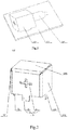
- Fig. 1 is a perspective view showing a capacitor-switch valve according to an exemplary embodiment of the present disclosure.
- Fig. 2 is a perspective view showing an explosion-proof casing according to an exemplary embodiment of the present disclosure.
- Fig. 3 is a schematic diagram showing a cross-shaped hole of an explosion-proof casing according to an exemplary embodiment of the present disclosure.
- the capacitor explosion-proof device includes an explosion-proof casing 100, covering a top of an electrolytic capacitor 300 opposing a plurality of pins of the capacitor.
- the explosion-proof casing 100 includes side plates. At least one vent 111 is provided on the side plate. The vent 111 is provided opposing the top.
- the electrolytic capacitor 300 is covered in the explosion-proof casing 100 through the explosion-proof casing 100. After the electrolytic capacitor 300 catches fire, the electrolyte and the electrolyte solution are ejected from the top of the electrolytic capacitor 300, the vaporized electrolyte solution is ejected through the vent 111, and the not-vaporized electrolyte solution and the electrolyte are blocked by the explosion-proof casing 100 and remain inside the explosion-proof casing 100, thereby avoiding spreading of the electrolyte solution that is catching fire, preventing spreading of electrolyte on fire to a large area, and effectively reducing the probability of fire.
- the material of the explosion-proof casing 100 may be various metals, flame-resistant material, or other materials, which is not limited herein. Those skilled in the art should understand that the application of various flame-resistant materials in the technical solutions involved in the present disclosure should fall within the scope of the protection of the present disclosure.
- the vent 111 is a cross-shaped hole provided in the center of the side plates.
- a ratio of width and length of the slit of the cross-shaped hole is 1: 4 ⁇ 8.
- the vent 111 is a round hole.
- the vent 111 may also be provided as a round hole, effectively blocking the not-vaporized electrolyte solution and electrolyte.
- a plurality of round holes is evenly distributed on the side plates.
- the plurality of round holes is provided on the side plates, which can reduce an area of a single hole, effectively blocking the not-vaporized electrolyte solution and electrolyte.
- providing the plurality of round holes increases an area for exhausting the vaporized electrolyte solution, and reducing the impact of airflow on the capacitor.
- vent may also be provided as other shapes, such as triangular, diamond or square, or the like.
- through holes of any regular or irregular shape can be used.
- the side plate includes a first plate 110, and opposing ends of the first plate 110 are provided with a second plate 120 and a third plate 130.
- the explosion-proof casing 100 further includes a top plate 140 connected with a first plate 110, a second plate 120 and a third plate 130.
- a first opening is formed on a side of the side plate opposing the first plate 110.
- a second opening is formed on a side of the side plate opposing the top plate 140.
- the side plate is made into a U-shape, the first opening is used to cover the capacitor 300, and the second opening is used to cover on the circuit board 200.
- the vent 111 is provided in the first plate 110; the extension plate 112 is provided at the end of the second opening of the first plate 110.
- the vent 111 is provided in the first plate 110, opposing to the top of the capacitor 300, which is beneficial to the emission of the vaporized electrolyte solution.
- the extension plate 112 is provided in the second opening, which facilitates the permanent connection to the circuit board 200.
- a second extension plate 121 is provided at the end of the second opening of the second plate 120, and a third extension plate 131 is provided at the end of the second opening of the third plate 130.
- the extension plates are provided at ends of the second opening of the second plate 120 and the third plate 130, which is fixed on the circuit board 200 together with the extension plate 112 at the end of the first plate 110, thereby increasing the strength of the explosion-proof casing 100, and effectively resisting the impact of the vaporized electrolyte solution.
- a circuit board having the capacitor explosion-proof device according to the above aspect or any one of the above embodiments.
- the circuit board 200 includes a fixing hole and an electrolytic capacitor 300.
- the capacitor explosion-proof device is fixed on the circuit board 200 panel through the fixing hole.
- the electrolytic capacitor 300 is accommodated in the space formed by the capacitor explosion-proof device and the circuit board 200 panel.
- an extension plate 112 is provided at an end of the side plate, the circuit board is provided with a fixing hole, and the extension plate 112 is connected to the fixing hole.
- the explosion-proof casing is fixed on the circuit board 200 through the fitting of the extension plate 112 and the fixing hole.
- the extension plate 112 may be made as a flat plate, and a screw hole matching the fixing hole of the circuit board 200 is processed on the flat plate at the bottom of the extension plate 112 and fixed by bolts or the like.
- An unthreaded hole may be processed on the flat plate, and the fixing is performed through fixing supports or other components.
- metal sheets are fixed around the fixing hole.
- metal sheets are attached to the periphery of the fixing hole, and the extension plate 112 and the metal sheets are soldered and connected by welding.
- the circuit board 200 When the circuit board 200 is manufactured, it can be soldered together with other electronic components, which is convenient to operate and improves the efficiency of manufacturing the circuit board.
- an electronic device provided with a power supply, including a capacitor-switch valve, the capacitor-switch valve being the capacitor-switch valve described in the above aspect.
- the capacitor-switch valve is electrically connected to the power supply.
- the capacitor-switch valve installed with the explosion-proof casing is applied to the electronic device.
- the capacitor 300 is covered in the explosion-proof casing through the explosion-proof casing 100. After the capacitor 300 catches fire, the electrolyte and the electrolyte solution are ejected from the top of the capacitor 300, the vaporized electrolyte solution is ejected through the vent, and the not-vaporized electrolyte solution and the electrolyte are blocked by the explosion-proof casing 100 and remain inside the explosion-proof casing 100, thereby avoiding spreading of the electrolyte solution to cause fire, preventing spreading of electrolyte on fire to a large area, and effectively reducing the probability of fire.
Landscapes
- Engineering & Computer Science (AREA)
- Power Engineering (AREA)
- Microelectronics & Electronic Packaging (AREA)
- Casings For Electric Apparatus (AREA)
- Electric Double-Layer Capacitors Or The Like (AREA)
Abstract
Description
- The present application is based on and claims the priority to the Chinese Patent Application No.
201911216524.3 filed on December 2, 2019 - The present disclosure relates to the technical field of electronic devices, and particularly to a capacitor explosion-proof device, a circuit board, and an electronic device.
- The rapid development of the electronic device technology has brought great convenience to users' work and life, and has been widely used in computers, communications, industrial processing, aviation and other fields. But at the same time, it also brings great security risks to the users. For example, in the process of using the electronic device, electric fires caused by a large amount of heat generated by electronic components have become an important disaster prevention project.
- For example, in electronic devices, firing caused after the valve of the electrolytic capacitor is opened is the reason for the majority of firing caused by electronic devices. The main reason is the opening of the valve of the electrolytic capacitor due to the overvoltage of the electrolytic capacitor caused by grid fluctuation, firing of the whole machine caused by the firing of the electrolyte solution after the valve is opened, and firing of the whole machine caused by the firing of the electrolyte solution after the valve is opened in a case where the production process of the electrolytic capacitor is defective.
- To overcome the problems in the related art, the present disclosure provides a capacitor explosion-proof device, a circuit board with an explosion-proof device, and an electronic device.
- According to an aspect of an embodiment of the present disclosure, a capacitor explosion-proof device is provided. The capacitor explosion-proof device includes an explosion-proof casing, covering a top of an electrolytic capacitor opposing a plurality of pins. The explosion-proof casing includes a side plate, at least one vent being provided on the side plate, and being provided opposing the top. In all embodiments of the present invention, the top of the electrolytic capacitor can be defined as follows: an electrolytic capacitor contains two ends, namely the lower end with the pins of the capacitor and on the opposite side the top of the capacitor. When an electrolytic capacitor is used on a circuit board, it is bent down to be parallel to the board by bending its pins. Since the top of the capacitor is explosive according to the present invention a casing is used for covering the top. The vent in the casing is used to release the gas when an explosion occurs.
- In one embodiment, the vent is a cross-shaped hole provided in a center of the side plate.
- In one embodiment, the vent is a round hole.
- In one embodiment, a plurality of round holes is evenly distributed on the side plate.
- In one embodiment, the side plate includes a first plate, and opposing two ends of the first plate are provided with a second plate and a third plate; the explosion-proof casing further includes a top plate, connected with the first plate, the second plate and the third plate; a first opening is formed on a side of the side plate opposing the first plate; and a second opening is formed on a side of the side plate opposing the top plate.
- In one embodiment, the vent is provided in the first plate; an extension plate is provided at an end of the second opening of the first plate.
- In one embodiment, a second extension plate is provided at an end of the second opening of the second plate, and a third extension plate is provided at an end of the second opening of the third plate.
- According to another aspect of the embodiments of the present disclosure, there is provided a circuit board having the capacitor explosion-proof device according to the above aspect or any one of the above embodiments, the circuit board includes: fixing holes; and an electrolytic capacitor, wherein the capacitor explosion-proof device is fixed on a panel of the circuit board through the fixing hole; the electrolytic capacitor is accommodated in a space formed by the capacitor explosion-proof device and the panel of the circuit board.
- In one embodiment, extension plates are provided at the ends of the side plate of the capacitor explosion-proof device. A fixing hole is provided on the circuit board, and the extension plates are connected to the fixing hole of the circuit board.
- In one embodiment, metal sheets are fixed on a periphery of the fixing hole.
- According to another aspect of an embodiment of the present disclosure, an electronic device is provided, including the circuit board as described in the above aspect or any one of the above embodiments.
- The technical solutions provided by the embodiments of the present disclosure may include following beneficial effects:
- avoiding spreading electrolyte solution to cause a fire, preventing the spread of fired electrolyte to a large area, and effectively reducing the probability of a fire.
- It should be noted that the above general description and the following detailed description are merely exemplary and explanatory and should not be construed as limiting of the disclosure.
- The accompanying drawings, which are incorporated in the specification and constitute a part of the specification, show exemplary embodiments of the present disclosure. The drawings along with the specification explain the principles of the present disclosure.
-
Fig. 1 is a perspective view showing a capacitor-switch valve according to an exemplary embodiment of the present disclosure. -
Fig. 2 is a perspective view showing an explosion-proof casing according to an exemplary embodiment of the present disclosure. -
Fig. 3 is a schematic diagram showing a cross-shaped hole of an explosion-proof casing according to an exemplary embodiment of the present disclosure. - Exemplary embodiments will be described in detail herein, examples of which are illustrated in the accompanying drawings. When referring to the drawings below, the same numerals in different drawings represent the same or similar elements, unless otherwise indicated. The implementations described in the following exemplary embodiments do not represent all implementations consistent with the present disclosure. Instead, they are merely examples of devices and methods consistent with aspects of the present disclosure as detailed in the appended claims.
-
Fig. 1 is a perspective view showing a capacitor-switch valve according to an exemplary embodiment of the present disclosure.Fig. 2 is a perspective view showing an explosion-proof casing according to an exemplary embodiment of the present disclosure.Fig. 3 is a schematic diagram showing a cross-shaped hole of an explosion-proof casing according to an exemplary embodiment of the present disclosure. - According to an aspect of an embodiment of the present disclosure, a capacitor explosion-proof device is provided. Referring to
Figs. 1 and 2 , the capacitor explosion-proof device includes an explosion-proof casing 100, covering a top of anelectrolytic capacitor 300 opposing a plurality of pins of the capacitor. The explosion-proof casing 100 includes side plates. At least onevent 111 is provided on the side plate. Thevent 111 is provided opposing the top. - The
electrolytic capacitor 300 is covered in the explosion-proof casing 100 through the explosion-proof casing 100. After theelectrolytic capacitor 300 catches fire, the electrolyte and the electrolyte solution are ejected from the top of theelectrolytic capacitor 300, the vaporized electrolyte solution is ejected through thevent 111, and the not-vaporized electrolyte solution and the electrolyte are blocked by the explosion-proof casing 100 and remain inside the explosion-proof casing 100, thereby avoiding spreading of the electrolyte solution that is catching fire, preventing spreading of electrolyte on fire to a large area, and effectively reducing the probability of fire. - The material of the explosion-
proof casing 100 may be various metals, flame-resistant material, or other materials, which is not limited herein. Those skilled in the art should understand that the application of various flame-resistant materials in the technical solutions involved in the present disclosure should fall within the scope of the protection of the present disclosure. - In one embodiment, the
vent 111 is a cross-shaped hole provided in the center of the side plates. - When a valve of the electrolytic capacitor is opened, a large amount of gas and liquid will be generated. The
vent 111 is set as the cross-shaped hole. Because the slit is small, a small amount of vaporized electrolyte solution will be ejected to the outside through the slit of the cross-shaped hole, thereby reducing the pressure of the gas inside the explosion-proof casing, preventing the electrolyte solution from accumulating, preventing the electrolyte solution from flowing to cause a larger hidden danger, and preventing the back spraying of the electrolyte or the electrolyte solution. A ratio of width and length of the slit of the cross-shaped hole is 1: 4 ∼ 8. In this embodiment, referring toFig. 3 , a ratio of the width of the slit, the length of the first slit and the length of the second slit can be set as W : L1: L2 = 1: 5: 7. - In one embodiment, the
vent 111 is a round hole. - The
vent 111 may also be provided as a round hole, effectively blocking the not-vaporized electrolyte solution and electrolyte. - In one embodiment, a plurality of round holes is evenly distributed on the side plates.
- The plurality of round holes is provided on the side plates, which can reduce an area of a single hole, effectively blocking the not-vaporized electrolyte solution and electrolyte. At the same time, providing the plurality of round holes increases an area for exhausting the vaporized electrolyte solution, and reducing the impact of airflow on the capacitor.
- It should be understood that the vent may also be provided as other shapes, such as triangular, diamond or square, or the like. As long as the vaporized electrolyte solution can be discharged out of the explosion-proof casing, through holes of any regular or irregular shape can be used. Those skilled in the art should understand that the application of through holes of various shapes in the technical solutions involved in the present disclosure should fall within the protection scope of the present disclosure.
- In one embodiment, the side plate includes a
first plate 110, and opposing ends of thefirst plate 110 are provided with asecond plate 120 and athird plate 130. The explosion-proof casing 100 further includes atop plate 140 connected with afirst plate 110, asecond plate 120 and athird plate 130. A first opening is formed on a side of the side plate opposing thefirst plate 110. A second opening is formed on a side of the side plate opposing thetop plate 140. - The side plate is made into a U-shape, the first opening is used to cover the
capacitor 300, and the second opening is used to cover on thecircuit board 200. - In one embodiment, the
vent 111 is provided in thefirst plate 110; theextension plate 112 is provided at the end of the second opening of thefirst plate 110. - The
vent 111 is provided in thefirst plate 110, opposing to the top of thecapacitor 300, which is beneficial to the emission of the vaporized electrolyte solution. Theextension plate 112 is provided in the second opening, which facilitates the permanent connection to thecircuit board 200. - In one embodiment, a
second extension plate 121 is provided at the end of the second opening of thesecond plate 120, and athird extension plate 131 is provided at the end of the second opening of thethird plate 130. - The extension plates are provided at ends of the second opening of the
second plate 120 and thethird plate 130, which is fixed on thecircuit board 200 together with theextension plate 112 at the end of thefirst plate 110, thereby increasing the strength of the explosion-proof casing 100, and effectively resisting the impact of the vaporized electrolyte solution. - According to another aspect of the embodiments of the present disclosure, there is provided a circuit board having the capacitor explosion-proof device according to the above aspect or any one of the above embodiments. The
circuit board 200 includes a fixing hole and anelectrolytic capacitor 300. The capacitor explosion-proof device is fixed on thecircuit board 200 panel through the fixing hole. Theelectrolytic capacitor 300 is accommodated in the space formed by the capacitor explosion-proof device and thecircuit board 200 panel. - In one embodiment, an
extension plate 112 is provided at an end of the side plate, the circuit board is provided with a fixing hole, and theextension plate 112 is connected to the fixing hole. - The explosion-proof casing is fixed on the
circuit board 200 through the fitting of theextension plate 112 and the fixing hole. Theextension plate 112 may be made as a flat plate, and a screw hole matching the fixing hole of thecircuit board 200 is processed on the flat plate at the bottom of theextension plate 112 and fixed by bolts or the like. An unthreaded hole may be processed on the flat plate, and the fixing is performed through fixing supports or other components. - In one embodiment, metal sheets are fixed around the fixing hole.
- As another embodiment, metal sheets are attached to the periphery of the fixing hole, and the
extension plate 112 and the metal sheets are soldered and connected by welding. When thecircuit board 200 is manufactured, it can be soldered together with other electronic components, which is convenient to operate and improves the efficiency of manufacturing the circuit board. - According to another aspect of an embodiment of the present disclosure, there is provided an electronic device provided with a power supply, including a capacitor-switch valve, the capacitor-switch valve being the capacitor-switch valve described in the above aspect. The capacitor-switch valve is electrically connected to the power supply.
- The capacitor-switch valve installed with the explosion-proof casing is applied to the electronic device. The
capacitor 300 is covered in the explosion-proof casing through the explosion-proof casing 100. After thecapacitor 300 catches fire, the electrolyte and the electrolyte solution are ejected from the top of thecapacitor 300, the vaporized electrolyte solution is ejected through the vent, and the not-vaporized electrolyte solution and the electrolyte are blocked by the explosion-proof casing 100 and remain inside the explosion-proof casing 100, thereby avoiding spreading of the electrolyte solution to cause fire, preventing spreading of electrolyte on fire to a large area, and effectively reducing the probability of fire. - Other embodiments of the present disclosure will be apparent to those skilled in the art from consideration of the specification and practice of the present disclosure disclosed herein. The present application is intended to cover any variations, uses, or adaptations of the present disclosure, which are in accordance with the general principles of the present disclosure and include common general knowledge or conventional technical means in the art that are not disclosed in the present disclosure. The specification and embodiments are merely illustrative, and the real scope of the present disclosure is defined by the appended claims.
- It should be understood that the present disclosure is not limited to the precise structures that have been described above and shown in the drawings, and various modifications and changes can be made without departing from the scope thereof. The scope of the present disclosure is limited only by the appended claims.
Claims (11)
- A capacitor explosion-proof device, comprising:an explosion-proof casing (100), covering a top of an electrolytic capacitor (300) opposing a plurality of pins of the electrolytic capacitor, and comprising a side plate;wherein at least one vent (111) is provided on the side plate, and is provided opposing the top.
- The capacitor explosion-proof device according to claim 1, wherein:
the vent (111) is a cross-shaped hole provided in a center of the side plate. - The capacitor explosion-proof device according to claim 1, wherein:
the vent (111) is a round hole. - The capacitor explosion-proof device according to claim 3, wherein:
a plurality of round holes is evenly distributed on the side plate. - The capacitor explosion-proof device according to claim 1, wherein:the side plate comprises a first plate (110), and opposing two ends of the first plate (110) are provided with a second plate (120) and a third plate (130);the explosion-proof casing (100) further comprises a top plate (140) connected with the first plate (110), the second plate (120) and the third plate (130);a first opening is formed on a side of the side plate opposing the first plate (110); anda second opening is formed on a side of the side plate opposing the top plate (140).
- The capacitor explosion-proof device according to claim 5, wherein:the vent (111) is provided in the first plate (110);an extension plate (112) is provided at an end of the second opening of the first plate (110).
- The capacitor explosion-proof device according to claim 6, wherein:
a second extension plate (121) is provided at an end of the second opening of the second plate (120), and a third extension plate (131) is provided at an end of the second opening of the third plate (130). - A circuit board (200), comprising the capacitor explosion-proof device according to any one of claims 1 to 7, further comprising:a fixing hole; andthe electrolytic capacitor (300) having the plurality of pins,wherein the capacitor explosion-proof device is fixed on a panel of the circuit board (200) through the fixing hole; the electrolytic capacitor (300) is accommodated in a space formed by the capacitor explosion-proof device and the panel of the circuit board (200).
- The circuit board according to claim 8, wherein:
extension plates (112) are provided at ends of the side plate of the capacitor explosion-proof device, and the extension plates (112) are connected to the fixing hole of the circuit board (200). - The circuit board according to claim 9, wherein:
metal sheets are fixed on a periphery of the fixing hole. - An electronic device, comprising the circuit board (200) according to any one of claims 8-10.
Applications Claiming Priority (1)
| Application Number | Priority Date | Filing Date | Title |
|---|---|---|---|
| CN201911216524.3A CN110911169A (en) | 2019-12-02 | 2019-12-02 | Capacitor explosion-proof device, circuit board and electronic device |
Publications (1)
| Publication Number | Publication Date |
|---|---|
| EP3832680A1 true EP3832680A1 (en) | 2021-06-09 |
Family
ID=69821380
Family Applications (1)
| Application Number | Title | Priority Date | Filing Date |
|---|---|---|---|
| EP20192004.8A Pending EP3832680A1 (en) | 2019-12-02 | 2020-08-20 | Capacitor explosion-proof device, circuit board and electronic device |
Country Status (3)
| Country | Link |
|---|---|
| US (1) | US11049665B2 (en) |
| EP (1) | EP3832680A1 (en) |
| CN (1) | CN110911169A (en) |
Families Citing this family (1)
| Publication number | Priority date | Publication date | Assignee | Title |
|---|---|---|---|---|
| CN114068179B (en) * | 2021-10-11 | 2023-01-10 | 湖南中达电子科技有限责任公司 | Explosion-proof capacitor |
Citations (4)
| Publication number | Priority date | Publication date | Assignee | Title |
|---|---|---|---|---|
| WO1984001468A1 (en) * | 1982-10-04 | 1984-04-12 | Matsushita Electric Industrial Co Ltd | Electrolytic condenser |
| JPH08138965A (en) * | 1994-11-10 | 1996-05-31 | Matsushita Electric Ind Co Ltd | Fireproof case of electrolytic capacitor with explosion-proof valve |
| EP2439758A1 (en) * | 2009-06-02 | 2012-04-11 | Kurita Water Industries Ltd. | Metallic electrolytic capacitor, and absorbent and leakage prevention material for metallic electrolytic capacitor |
| US20180226199A1 (en) * | 2017-02-03 | 2018-08-09 | Samsung Electronics Co., Ltd. | Explosion-proof apparatus |
Family Cites Families (7)
| Publication number | Priority date | Publication date | Assignee | Title |
|---|---|---|---|---|
| CN201700093U (en) * | 2010-01-20 | 2011-01-05 | 广州擎天实业有限公司 | Capacitor explosion-proof box for rectifying device |
| CN206463675U (en) * | 2017-02-04 | 2017-09-05 | 北京巴尔福过滤技术有限公司 | Sinter-plate precipitator with explosion-protection equipment |
| CN107444561B (en) * | 2017-08-16 | 2022-10-11 | 二工防爆科技股份有限公司 | Explosion-proof electric bicycle |
| CN207205672U (en) * | 2017-08-29 | 2018-04-10 | 华南理工大学 | A kind of racing car welding clamp of vehicle frame based on splicing construction |
| JP2019220596A (en) * | 2018-06-21 | 2019-12-26 | アルパイン株式会社 | Electronic unit |
| CN209434267U (en) * | 2019-04-22 | 2019-09-24 | 杭州威宏能源科技有限公司 | A kind of high safety ignition power |
| CN211604935U (en) * | 2019-12-02 | 2020-09-29 | 北京小米移动软件有限公司 | Capacitor explosion-proof devices, circuit boards and electronic devices |
-
2019
- 2019-12-02 CN CN201911216524.3A patent/CN110911169A/en active Pending
-
2020
- 2020-06-10 US US16/898,386 patent/US11049665B2/en active Active
- 2020-08-20 EP EP20192004.8A patent/EP3832680A1/en active Pending
Patent Citations (4)
| Publication number | Priority date | Publication date | Assignee | Title |
|---|---|---|---|---|
| WO1984001468A1 (en) * | 1982-10-04 | 1984-04-12 | Matsushita Electric Industrial Co Ltd | Electrolytic condenser |
| JPH08138965A (en) * | 1994-11-10 | 1996-05-31 | Matsushita Electric Ind Co Ltd | Fireproof case of electrolytic capacitor with explosion-proof valve |
| EP2439758A1 (en) * | 2009-06-02 | 2012-04-11 | Kurita Water Industries Ltd. | Metallic electrolytic capacitor, and absorbent and leakage prevention material for metallic electrolytic capacitor |
| US20180226199A1 (en) * | 2017-02-03 | 2018-08-09 | Samsung Electronics Co., Ltd. | Explosion-proof apparatus |
Also Published As
| Publication number | Publication date |
|---|---|
| CN110911169A (en) | 2020-03-24 |
| US20210166887A1 (en) | 2021-06-03 |
| US11049665B2 (en) | 2021-06-29 |
Similar Documents
| Publication | Publication Date | Title |
|---|---|---|
| EP3832680A1 (en) | Capacitor explosion-proof device, circuit board and electronic device | |
| TWM440625U (en) | Casing of electronic apparatus | |
| CN106612597B (en) | Electric control box and air conditioner | |
| KR101506081B1 (en) | Electromagnetic pulse protecting cabinet | |
| CN211604935U (en) | Capacitor explosion-proof devices, circuit boards and electronic devices | |
| US11571596B2 (en) | Fire arrester and fire resistant structure of a fire safety cabinet | |
| CN104981127A (en) | Flame-retardant electrical control cabinet | |
| CN222484757U (en) | TV set | |
| CN217985639U (en) | Explosion-proof structure and specific phototaxis band granary pest trapping equipment | |
| WO2015106693A1 (en) | Aluminium electrolytic capacitor | |
| CN101304140B (en) | Power supply plug terminal with surge protection function | |
| CN115103538A (en) | Explosion-proof structure and specific phototaxis band granary pest trapping equipment | |
| CN112490878B (en) | High-low voltage switch cabinet with explosion-proof function | |
| CN213237599U (en) | Closed ignition device for pressure burner | |
| CN211125218U (en) | Varistor protective structure and control cabinet | |
| CN204466031U (en) | A kind of disc electrostatic defending PCB | |
| CN201421807Y (en) | Flicking type explosion-proof and flame-proof safety surge absorption module | |
| CN210200437U (en) | SMD communication line protector | |
| CN213094625U (en) | Explosion-proof electrical apparatus case shell | |
| CN110707565A (en) | Fireproof heat dissipation power distribution cabinet | |
| CN214502239U (en) | A smoke generating device capable of leak detection | |
| CN217882564U (en) | Ring main unit cable chamber bottom plate and ring main unit | |
| US20080297968A1 (en) | Surge discharging device | |
| CN207625979U (en) | A kind of heat conduction screening arrangement for signal Surge Protector | |
| CN108417422A (en) | A kind of arc-control device |
Legal Events
| Date | Code | Title | Description |
|---|---|---|---|
| PUAI | Public reference made under article 153(3) epc to a published international application that has entered the european phase |
Free format text: ORIGINAL CODE: 0009012 |
|
| STAA | Information on the status of an ep patent application or granted ep patent |
Free format text: STATUS: THE APPLICATION HAS BEEN PUBLISHED |
|
| AK | Designated contracting states |
Kind code of ref document: A1 Designated state(s): AL AT BE BG CH CY CZ DE DK EE ES FI FR GB GR HR HU IE IS IT LI LT LU LV MC MK MT NL NO PL PT RO RS SE SI SK SM TR |
|
| STAA | Information on the status of an ep patent application or granted ep patent |
Free format text: STATUS: REQUEST FOR EXAMINATION WAS MADE |
|
| 17P | Request for examination filed |
Effective date: 20211209 |
|
| RBV | Designated contracting states (corrected) |
Designated state(s): AL AT BE BG CH CY CZ DE DK EE ES FI FR GB GR HR HU IE IS IT LI LT LU LV MC MK MT NL NO PL PT RO RS SE SI SK SM TR |
|
| STAA | Information on the status of an ep patent application or granted ep patent |
Free format text: STATUS: EXAMINATION IS IN PROGRESS |
|
| 17Q | First examination report despatched |
Effective date: 20230921 |
|
| GRAP | Despatch of communication of intention to grant a patent |
Free format text: ORIGINAL CODE: EPIDOSNIGR1 |
|
| STAA | Information on the status of an ep patent application or granted ep patent |
Free format text: STATUS: GRANT OF PATENT IS INTENDED |
|
| RIC1 | Information provided on ipc code assigned before grant |
Ipc: H01G 9/12 20060101AFI20260108BHEP Ipc: H01G 2/06 20060101ALI20260108BHEP Ipc: H01G 9/00 20060101ALI20260108BHEP Ipc: H01G 9/08 20060101ALN20260108BHEP Ipc: H01G 9/008 20060101ALN20260108BHEP |
|
| INTG | Intention to grant announced |
Effective date: 20260119 |
|
| RIC1 | Information provided on ipc code assigned before grant |
Ipc: H01G 9/12 20060101AFI20260112BHEP Ipc: H01G 2/06 20060101ALI20260112BHEP Ipc: H01G 9/00 20060101ALI20260112BHEP Ipc: H01G 9/08 20060101ALN20260112BHEP Ipc: H01G 9/008 20060101ALN20260112BHEP |