EP3832604A1 - Animation control method and device, storage medium, and electronic device - Google Patents
Animation control method and device, storage medium, and electronic device Download PDFInfo
- Publication number
- EP3832604A1 EP3832604A1 EP19893340.0A EP19893340A EP3832604A1 EP 3832604 A1 EP3832604 A1 EP 3832604A1 EP 19893340 A EP19893340 A EP 19893340A EP 3832604 A1 EP3832604 A1 EP 3832604A1
- Authority
- EP
- European Patent Office
- Prior art keywords
- target
- rotation
- matrix
- angle
- adjusted
- Prior art date
- Legal status (The legal status is an assumption and is not a legal conclusion. Google has not performed a legal analysis and makes no representation as to the accuracy of the status listed.)
- Pending
Links
Images


Classifications
-
- A—HUMAN NECESSITIES
- A63—SPORTS; GAMES; AMUSEMENTS
- A63F—CARD, BOARD, OR ROULETTE GAMES; INDOOR GAMES USING SMALL MOVING PLAYING BODIES; VIDEO GAMES; GAMES NOT OTHERWISE PROVIDED FOR
- A63F13/00—Video games, i.e. games using an electronically generated display having two or more dimensions
- A63F13/55—Controlling game characters or game objects based on the game progress
-
- G—PHYSICS
- G06—COMPUTING OR CALCULATING; COUNTING
- G06T—IMAGE DATA PROCESSING OR GENERATION, IN GENERAL
- G06T13/00—Animation
- G06T13/20—Three-dimensional [3D] animation
-
- G—PHYSICS
- G06—COMPUTING OR CALCULATING; COUNTING
- G06T—IMAGE DATA PROCESSING OR GENERATION, IN GENERAL
- G06T13/00—Animation
- G06T13/20—Three-dimensional [3D] animation
- G06T13/40—Three-dimensional [3D] animation of characters, e.g. humans, animals or virtual beings
-
- A—HUMAN NECESSITIES
- A63—SPORTS; GAMES; AMUSEMENTS
- A63F—CARD, BOARD, OR ROULETTE GAMES; INDOOR GAMES USING SMALL MOVING PLAYING BODIES; VIDEO GAMES; GAMES NOT OTHERWISE PROVIDED FOR
- A63F13/00—Video games, i.e. games using an electronically generated display having two or more dimensions
- A63F13/30—Interconnection arrangements between game servers and game devices; Interconnection arrangements between game devices; Interconnection arrangements between game servers
- A63F13/35—Details of game servers
-
- A—HUMAN NECESSITIES
- A63—SPORTS; GAMES; AMUSEMENTS
- A63F—CARD, BOARD, OR ROULETTE GAMES; INDOOR GAMES USING SMALL MOVING PLAYING BODIES; VIDEO GAMES; GAMES NOT OTHERWISE PROVIDED FOR
- A63F13/00—Video games, i.e. games using an electronically generated display having two or more dimensions
- A63F13/55—Controlling game characters or game objects based on the game progress
- A63F13/56—Computing the motion of game characters with respect to other game characters, game objects or elements of the game scene, e.g. for simulating the behaviour of a group of virtual soldiers or for path finding
-
- G—PHYSICS
- G06—COMPUTING OR CALCULATING; COUNTING
- G06T—IMAGE DATA PROCESSING OR GENERATION, IN GENERAL
- G06T15/00—Three-dimensional [3D] image rendering
- G06T15/10—Geometric effects
- G06T15/20—Perspective computation
-
- G—PHYSICS
- G06—COMPUTING OR CALCULATING; COUNTING
- G06T—IMAGE DATA PROCESSING OR GENERATION, IN GENERAL
- G06T19/00—Manipulating three-dimensional [3D] models or images for computer graphics
- G06T19/20—Editing of three-dimensional [3D] images, e.g. changing shapes or colours, aligning objects or positioning parts
-
- G—PHYSICS
- G06—COMPUTING OR CALCULATING; COUNTING
- G06T—IMAGE DATA PROCESSING OR GENERATION, IN GENERAL
- G06T3/00—Geometric image transformations in the plane of the image
- G06T3/40—Scaling of whole images or parts thereof, e.g. expanding or contracting
- G06T3/4007—Scaling of whole images or parts thereof, e.g. expanding or contracting based on interpolation, e.g. bilinear interpolation
-
- G—PHYSICS
- G06—COMPUTING OR CALCULATING; COUNTING
- G06T—IMAGE DATA PROCESSING OR GENERATION, IN GENERAL
- G06T7/00—Image analysis
- G06T7/60—Analysis of geometric attributes
-
- G—PHYSICS
- G06—COMPUTING OR CALCULATING; COUNTING
- G06T—IMAGE DATA PROCESSING OR GENERATION, IN GENERAL
- G06T2213/00—Indexing scheme for animation
- G06T2213/12—Rule based animation
-
- G—PHYSICS
- G06—COMPUTING OR CALCULATING; COUNTING
- G06T—IMAGE DATA PROCESSING OR GENERATION, IN GENERAL
- G06T2219/00—Indexing scheme for manipulating 3D models or images for computer graphics
- G06T2219/20—Indexing scheme for editing of 3D models
- G06T2219/2016—Rotation, translation, scaling
Definitions
- This application relates to the field of animation, and in particular, to animation control.
- an inverse kinematics (IK) animation based on that child bone nodes drive a parent bone node to move is also widely applied to game engines.
- the IK animation is to inversely derive movement of other bones according to a position of a bone at the end. For example, a hand is extended to catch a cup. The position of the cup is a target, and the IK animation resolves an animation from fingers to an arm.
- the advantage of the IK animation is to calculate the animation in real time without participation of the fine art. For the scenario in which the eyeballs always face toward the camera, once an orientation of the eyeballs is specified, an IK system automatically calculates orientations of the eyeballs, a head, and a neck.
- Embodiments of this application provide an animation control method and apparatus, a storage medium, and an electronic device, to resolve at least the technical problem of the inflexibility of animation control manners.
- an animation control method applicable to an electronic device, the method including: obtaining a first position of a virtual camera in an animation and a second position of a to-be-adjusted target in the animation; determining a rotation angle for the to-be-adjusted target according to the first position, the second position, and coordinate information of a target object to which the to-be-adjusted target belongs; adjusting the rotation angle by using a rotation coefficient to obtain a target angle, the rotation coefficient being used for adjusting a ratio of the rotation angle of the to-be-adjusted target to a rotation angle of an associated target, and the associated target being a target having a linkage relationship with the to-be-adjusted target; and controlling the to-be-adjusted target to rotate according to the target angle, to cause the rotated to-be-adjusted target to face toward the virtual camera.
- an animation control apparatus is further provided, applicable to an electronic device, including: an obtaining unit, configured to obtain a first position of a virtual camera in an animation and a second position of a to-be-adjusted target in the animation; a determining unit, configured to determine a rotation angle for the to-be-adjusted target according to the first position, the second position, and coordinate information of a target object to which the to-be-adjusted target belongs; an adjusting unit, configured to adjust the rotation angle by using a rotation coefficient to obtain a target angle, the rotation coefficient being used for adjusting a ratio of the rotation angle of the to-be-adjusted target to a rotation angle of an associated target, and the associated target being a target having a linkage relationship with the to-be-adjusted target; and a control unit, configured to control the to-be-adjusted target to rotate according to the target angle, to cause the rotated to-be-ad
- a storage medium is further provided.
- the storage medium stores a computer program.
- the computer program when being executed, is configured to perform the foregoing method.
- an electronic device is further provided.
- the electronic device includes a memory and a processor.
- the memory stores a computer program.
- the processor is configured to perform the foregoing method by using the computer program.
- a computer program product including instructions is further provided.
- the instructions when run on a computer, cause the computer to perform the foregoing method.
- a matrix expression of coordinates of the to-be-adjusted target is determined.
- a rotation angle for the to-be-adjusted target is then determined according to the coordinates of the to-be-adjusted target.
- the rotation angle may be adjusted according to an inputted rotation coefficient to obtain a target angle.
- the to-be-adjusted target is controlled to be adjusted according to the target angle, to make the rotation of the to-be-adjusted target more flexible and the expressed effect more natural, thereby resolving the technical problem of inflexibility of rotation angle adjustment in the related art.
- an animation control method is provided.
- the animation control method may be applied to a hardware environment formed by a terminal 101 as shown in FIG. 1 .
- the terminal 101 adjusts an orientation of a to-be-adjusted target by performing the animation control method of this application.
- the foregoing hardware environment may further include a server 102 providing a business service (for example, a game service) to the terminal 101.
- the server 102 performs the animation control method of this application and provides a performing result as a part of the service (for example, the game service) to the terminal 101, to adjust an orientation of a to-be-adjusted target on the terminal.
- the terminal 101 may be connected to the server 102 through a network.
- the network includes, but is not limited to, a wide area network, a metropolitan area network, or a local area network.
- the terminal 101 may be a mobile phone terminal, a PC terminal, a notebook terminal, or a tablet computer terminal.
- Scenes to which the technical solution of this application is applicable include, but are not limited to, the following scenes.
- the technical solution of this application may be applicable to a social scene in which a technology such as augmented reality (AR) or virtual reality (VR) is used.
- the social scene may be provided by the foregoing terminal 101, and the server 102 synchronizes a social behavior in the social scene.
- the social scene includes a target object to which the to-be-adjusted target belongs.
- the target object may be an object such as a virtual character corresponding to a current user in the social scene, a virtual friend of the current user in the social scene, a virtual stranger in the social scene, or a virtual pet of the current user in the social scene.
- the server may adjust an orientation of a to-be-adjusted target on the target object by performing the technical solution of this application, for example, adjusting eyes to always face toward a virtual camera, and deliver an adjustment result to each terminal, so that the each terminal synchronously renders a picture in which the eyes of the target object always face toward a screen (a picture played on the screen is the picture rendered in the perspective of the virtual camera).
- the technical solution of this application may be further applicable to a game scene, for example, a multiplayer online battle arena (MOBA) game, a first-person shooter (FPS) game, or a third-person shooter (TPS) game.
- An application of the foregoing game may be installed on the terminal 101 to form a client of the game.
- a player plays the game in the game scene by using the client.
- the game scene includes a target object to which a to-be-adjusted target belongs.
- the target object may be an object such as a game role operated by a current user in the game scene, a teammate of the game role, or an enemy of the game role.
- the to-be-adjusted target may be an organ of a character role or a part of a body structure, such as eyes.
- a player plays a game in a game scene, and if the game is a stand-alone game or a local multiplayer game, one terminal may adjust an orientation of a to-be-adjusted target on a target object by performing the technical solution of this application and synchronize a performing result to other terminals.
- the server 102 may adjust the orientation of the to-be-adjusted target on the target object by performing the technical solution of this application and synchronize a performing result to terminals participating in the game.
- FIG. 2 is a flowchart of an optional animation control method according to an embodiment of this application. As shown in FIG. 2 , the animation control method includes the following steps.
- a terminal obtains a first position of a virtual camera in an animation and a second position of a to-be-adjusted target in the animation.
- the to-be-adjusted target may be a part of the object.
- the object may be a character role.
- the to-be-adjusted target may be an organ of the character role or a part of a body structure, such as eyes.
- the animation may be a game animation.
- the to-be-adjusted target may be eyes of a game role.
- the first position is a position of the virtual camera in the animation.
- the second position is a position of the to-be-adjusted target in the animation.
- a game scene and each role in the game scene may be rendered by a game engine.
- the second position of the to-be-adjusted target in the animation rendered by the game engine may be obtained in the game engine, and the first position of the virtual camera may be obtained by using a configuration file (a state, a moving logic, and the like of each virtual camera are configured in the configuration file) of the game engine.
- Both the first position and the second position may be expressed by three-dimensional coordinates.
- the three-dimensional coordinates may be expressed by using a matrix.
- the terminal determines a rotation angle for the to-be-adjusted target according to the first position, the second position, and coordinate information of a target object to which the to-be-adjusted target belongs.
- a vector heading from the second position to the first position is obtained (the vector may be a vector in a three-dimensional coordinate system).
- an x-axis coordinate of the to-be-adjusted target is obtained by multiplying the vector by a matrix [0 0 1];
- a y-axis coordinate of the to-be-adjusted target is obtained by multiplying the vector by a matrix [0 1 0];
- a z-axis coordinate of the to-be-adjusted target is obtained by multiplying the vector by a matrix [1 0 0]. Therefore, a matrix expression of the coordinates of the to-be-adjusted target in a three-dimensional space is obtained.
- the matrix is a rotation matrix M r (that is, a first matrix).
- a rotation matrix M t that is, a second matrix
- a rotation matrix M i that is, a third matrix
- the coordinate information of the target object includes the rotation matrix M t and the rotation matrix M i
- the rotation matrix M t and the rotation matrix M i may be obtained by using the game engine.
- each of M i , M t ⁇ 1 , M r is a 3 ⁇ 3 matrix.
- the rotation matrix M t represents a rotation matrix corresponding to the game role which is under control of the player and the control operation of the player (that is, a conversion matrix from a state before control to a state after control).
- the rotation matrix M t and the rotation matrix M i of the role in the initial state may be obtained through an application programming interface (API) provided by the game engine:
- M i i 11 i 12 i 13 i 21 i 22 i 23 i 31 i 32 i 33 , where i 11 to i 33 are constants;
- M t t 11 t 12 t 13 t 21 t 22 t 23 t 31 t 32 t 33 , where t 11 to t 33 are constants;
- M r r 11 r 12 r 13 r 21 r 22 r 23 r 31 r 32 r 23 , where r 11 to r 33 are constants which are values calculated according to the vector heading from the second position to the first position; and
- the determining a rotation angle for the to-be-adjusted target according to the first position, the second position, and coordinate information of a target object to which the to-be-adjusted target belongs includes: obtaining a first matrix of the to-be-adjusted target according to a vector heading from the second position to the first position; obtaining a rotation matrix of the target object as a second matrix, the second matrix being a matrix used when the target object is controlled to rotate in a preset scene; obtaining a rotation matrix of the target object in an initial state as a third matrix; cascading the first matrix, the second matrix, and the third matrix to obtain a target matrix; and converting the target matrix into the rotation angle.
- the first matrix is the rotation matrix M r
- the second matrix is the rotation matrix M t
- the third matrix is the rotation matrix Mi.
- the rotation angle may include an angle ⁇ x relative to an X-axis, an angle ⁇ y relative to a Y-axis, and an angle ⁇ z relative to a Z-axis.
- the terminal adjusts the rotation angle by using a rotation coefficient to obtain a target angle.
- the to-be-adjusted target faces toward to the virtual camera.
- the target angle represents an angle difference between an angle before the adjustment and an angle when the virtual camera is faced rightly
- the to-be-adjusted target which is adjusted according to the target angle faces toward the virtual camera.
- the rotation coefficient is used for adjusting a ratio of the rotation angle of the to-be-adjusted target to that of an associated target, and the associated target is a target with a linkage relationship with the to-be-adjusted target.
- the rotation coefficient is preset by way of fine art animation.
- rotation of a part of the role may cause linkage of other parts, or other related parts are rotated at the same time when a part is rotated, making a rotation effect more natural. Therefore, when the to-be-adjusted target is rotated, rotation angles of other associated targets need to be considered, that is, a ratio (that is, the foregoing rotation coefficient) of the rotation angle is set for the to-be-adjusted target and the associated targets.
- the to-be-adjusted target is eyes of the role
- the associated targets include a head and a neck of the role
- a rotation ratio of the eyes to the head to the neck is 3:2:1.
- M is obtained by substituting values of the elements in M i , M t ⁇ 1 , M r .
- the head is rotated by 20° (that is, subtracting 20° from an angle between the head and the X-axis)
- the neck is rotated by 10° (that is, subtracting 10° from an angle between the neck and the X-axis).
- the rotation coefficient of the to-be-rotated target may be 3, a rotation ratio of the to-be-rotated target to the head is 3:2, and a rotation ratio of the to-be-rotated target to the neck is 3:1.
- the rotation coefficient herein may be set according to different positions of the to-be-adjusted target in the object, to enable the to-be-adjusted target after being rotated according to the target angle to face toward the virtual camera and enable the object to move relatively natural. As shown in FIG. 4 , the eyes are rotated by 30°, the head is rotated by 20°, and the neck is rotated by 10°.
- Rotation manners of rotation angles relative to the Y-axis and Z-axis are similar to that of the rotation angle relative to the X-axis.
- the terminal controls the to-be-adjusted target to rotate according to the target angle, so that the rotated to-be-adjusted target faces toward the virtual camera.
- a matrix expression of coordinates of the to-be-adjusted target is determined.
- a rotation angle of the to-be-adjusted target is determined according to the coordinates of the to-be-adjusted target.
- the rotation angle may be adjusted according to an inputted rotation coefficient to obtain a target angle.
- the to-be-adjusted target is controlled to be adjusted according to the target angle, to make the rotation of the to-be-adjusted target more flexible and the expressed effect more natural, thereby resolving the technical problem of inflexibility of rotation angle adjustment in the related art.
- the controlling the to-be-adjusted target to rotate according to the target angle includes: obtaining a current rotation matrix (the current rotation matrix is similar to the rotation matrix M t and rotation matrix Mi, and may be obtained through the API provided by the game engine) of the to-be-adjusted target, for a game role the rotation including two parts: one being rotation of the entire game role under control of the player, the current rotation matrix being used for representing rotation of the entire role at present; the other being rotation for enabling the to-be-adjusted target to always face toward the virtual camera and being represented by a target matrix or a target angle converted from a target matrix, and final rotation being obtained by superimposing the two parts; and applying the target angle to the current rotation matrix to obtain a target matrix, a rotation angle represented by the target matrix being an angle at which the to-be-adjusted target faces toward the virtual camera.
- the to-be-adjusted target is controlled to rotate to the target matrix, so that the to-be-a
- the current rotation matrix is multiplied by the matrix M a representing the target angle, to rotate the to-be-adjusted target based on a product matrix of M e and M a .
- the to-be-adjusted target after the rotation faces toward the virtual camera.
- the requirement herein may refer to a requirement in the game at a specific moment for the to-be-adjusted target to face toward the virtual camera, or for the to-be-adjusted target to face toward the virtual camera in an entire game process.
- the animation control method provided in the embodiments of this application further includes: setting a time required for rotation of the to-be-adjusted target as rotation time; and performing linear interpolation on the rotation angle according to the rotation time to obtain an interpolated rotation angle, so that the interpolated rotation angle is adjusted by using the rotation coefficient to obtain the target angle, the target angle being obtained by multiplying the interpolated rotation angle by the rotation coefficient.
- Time of obtaining the "rotation time” is not limited in the embodiments of this application, and the obtaining only needs to be completed before the "performing linear interpolation on the rotation angle according to the rotation time” is performed.
- one linear interpolation is performed on the rotation angle according to time, that is, a time required for rotation is set, and may be adjusted by multiplying the interpolated rotation angle and the rotation coefficient. For example, in a case that the rotation angle is 30°, and if the rotation time is one second, the to-be-adjusted target is controlled to rotate by 30° in one second; and if the rotation time is five seconds, the to-be-adjusted target is controlled to rotate by 30° in five seconds.
- the linear interpolation only changes the time required for the rotation, but not change the angle of the rotation of the to-be-adjusted target.
- the rotation time is set to five seconds, so that the effect of slow rotation of the to-be-adjusted target may be expressed.
- controlling the to-be-adjusted target to rotate according to the target angle includes: obtaining a rotation coefficient of at least one associated target as at least one rotation coefficient; applying the at least one rotation coefficient to a corresponding associated target among the at least one associated targets to obtain at least one rotation angle; and controlling the at least one associated target and the to-be-adjusted target to rotate in a hierarchical order according to the target angle and the at least one rotation angle.
- the rotation angles of the associated targets are determined.
- the to-be-adjusted target is eyes of a role
- the associated targets include a head and a neck of the role, and a rotation ratio of the eyes to the head to the neck is 3:2:1.
- a target angle of the eyes is 30°
- the head is rotated by 20°
- the neck is rotated by 10°.
- a bone A represents the neck
- a bone B represents the head
- a bone C represents the eyes.
- the hierarchical order of the bones is from the bone A to the bone B to the bone C.
- a rotation angle of the bone A is calculated first, rotation is then adjusted according to a fine art input, that is, the rotation angle of the bone A is adjusted according to an inputted rotation coefficient, and the adjusted rotation is superimposed onto the existing rotation, that is, superimposed onto a current rotation angle of the bone A, to complete rotation of the bone A.
- a rotation angle of the bone B is calculated, rotation is then adjusted according to a fine art input, that is, the rotation angle of the bone B is adjusted according to an inputted rotation coefficient, and the adjusted rotation is superimposed onto the existing rotation, that is, superimposed onto a current rotation angle of the bone B, to complete rotation of the bone B.
- a rotation angle of the bone C is calculated, rotation is then adjusted according to a fine art input, that is, the rotation angle of the bone C is adjusted according to an inputted rotation coefficient, and the adjusted rotation is superimposed onto the existing rotation, that is, superimposed onto a current rotation angle of the bone C, to complete rotation of the bone C.
- the rotation angles of the bone A and the bone B may be directly obtained according to the rotation coefficient after the rotation angle of the bone C is calculated, to complete hierarchical rotation from the bone A to the bone C, and a final rotation result may refer to FIG. 4 .
- an angle between eyes of a character (equivalent to the bone C) and the X-axis is reduced by 30°
- an angle between a head (equivalent to the bone A) and the X-axis and an angle between a neck (equivalent to the bone B) and the X-axis are reduced by 20° and 10° respectively.
- the effect of eyeballs tracking the camera may be generated in real time, the animation is smooth and natural with no artifact, and an animation of another part of the body is not affected, for example, an animation of blinking while turning the head to look at you.
- the technical solution of this application is a solution for adjusting a part (that is, a to-be-adjusted target) of a target object in a virtual scene to face toward a virtual camera.
- the virtual scene may be one of the foregoing game scene or the social scene.
- the computer software product is stored in a storage medium (for example, a read-only memory (ROM)/random access memory (RAM), a magnetic disk, or an optical disc), and includes several instructions for instructing a terminal device (which may be a mobile phone, a computer, a server, a network device, or the like) to perform the method described in the embodiments of this application.
- a storage medium for example, a read-only memory (ROM)/random access memory (RAM), a magnetic disk, or an optical disc
- a terminal device which may be a mobile phone, a computer, a server, a network device, or the like
- FIG. 6 is a schematic diagram of an optional animation control apparatus according to an embodiment of this application. As shown in FIG. 6 , the apparatus may include:
- a matrix expression of coordinates of the to-be-adjusted target is determined.
- a rotation angle for the to-be-adjusted target is then determined according to the coordinates of the to-be-adjusted target.
- the rotation angle may be adjusted according to an inputted rotation coefficient to obtain a target angle.
- the to-be-adjusted target is controlled to be adjusted according to the target angle, to make the rotation of the to-be-adjusted target more flexible and the expressed effect more natural, thereby resolving the technical problem of inflexibility of rotation angle adjustment in the related art.
- the determining unit 604 includes:
- control unit 608 includes: a fourth obtaining module, configured to obtain a current rotation matrix of the to-be-adjusted target; a first application module, configured to apply the target angle to the current rotation matrix to obtain a target matrix, a rotation angle represented by the target matrix being an angle at which the to-be-adjusted target faces toward the virtual camera; and a rotation module, configured to control the to-be-adjusted target to rotate to the target matrix.
- the apparatus further includes: a setting unit, configured to set a time required for rotation of the to-be-adjusted target to obtain rotation time; and an interpolation unit, configured to perform linear interpolation on the rotation angle according to the rotation time to obtain an interpolated rotation angle, the target angle being obtained by multiplying the interpolated rotation angle by the rotation coefficient; and the adjusting unit 606 is specifically configured to adjust the interpolated rotation angle by using the rotation coefficient to obtain the target angle.
- a setting unit configured to set a time required for rotation of the to-be-adjusted target to obtain rotation time
- an interpolation unit configured to perform linear interpolation on the rotation angle according to the rotation time to obtain an interpolated rotation angle, the target angle being obtained by multiplying the interpolated rotation angle by the rotation coefficient
- the adjusting unit 606 is specifically configured to adjust the interpolated rotation angle by using the rotation coefficient to obtain the target angle.
- control unit 608 includes: a fifth obtaining module, configured to obtain a rotation coefficient of at least one associated target to obtain at least one rotation coefficient; a second application module, configured to apply the at least one rotation coefficient to a corresponding associated target among the at least one associated targets to obtain at least one rotation angle; and a control module, configured to control the at least one associated target and the to-be-adjusted target to rotate in a hierarchical order according to the target angle and the at least one rotation angle.
- a fifth obtaining module configured to obtain a rotation coefficient of at least one associated target to obtain at least one rotation coefficient
- second application module configured to apply the at least one rotation coefficient to a corresponding associated target among the at least one associated targets to obtain at least one rotation angle
- control module configured to control the at least one associated target and the to-be-adjusted target to rotate in a hierarchical order according to the target angle and the at least one rotation angle.
- an electronic device configured to implement the foregoing animation control method.
- the electronic device includes a memory and a processor, the memory storing a computer program, and the processor being configured to perform steps in any one of the foregoing method embodiments by using the computer program.
- the electronic device may be a terminal or a server, which is not specifically limited in the embodiments of this application.
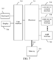
- FIG. 7 is a schematic diagram of an optional electronic device according to an embodiment of this application.
- the electronic device may include: one or more (only one processor is shown in FIG. 7 ) processors 701, at least one communication bus 702, a user interface 703, at least one transmission apparatus 704, and a memory 705.
- the communication bus 702 is configured to implement connection communication between the components.
- the user interface 703 may include a display 706 and a keyboard 707.
- the transmission apparatus 704 may optionally include a standard wired interface and wireless interface.
- the electronic device may be located in at least one of a plurality of network devices of a computer network.
- the processor may be configured to perform the following steps through a computer program:
- the electronic device may alternatively be a terminal device such as a smartphone (for example, an Android mobile phone or an iOS mobile phone), a tablet computer, a palmtop computer, a mobile Internet device (MID), or a PAD.
- a terminal device such as a smartphone (for example, an Android mobile phone or an iOS mobile phone), a tablet computer, a palmtop computer, a mobile Internet device (MID), or a PAD.
- FIG. 7 does not limit the structure of the electronic device.
- the electronic device may alternatively include more or fewer components (such as a network interface and a display apparatus) than those shown in FIG. 7 , or have configurations different from that shown in FIG. 7 .
- the memory 705 may be configured to store a software program and a module, for example, a program instruction/module corresponding to the apparatus in the embodiments of this application, and the processor 701 performs various functional applications and data processing by running the software program and the module stored in the memory 705, that is, implementing the foregoing any implementation of the animation control method provided above.
- the memory 705 may include a high-speed RAM, and may further include a non-volatile memory such as one or more magnetic storage apparatuses, a flash memory, or another non-volatile solid-state memory.
- the memory 705 may further include memories remotely disposed relative to the processor 701, and these remote memories may be connected to the terminal through a network. Examples of the network include, but are not limited to, the Internet, an intranet, a local area network, a mobile communication network, and a combination thereof.
- the transmission apparatus 704 is configured to receive or transmit data through a network.
- the network may include a wired network and a wireless network.
- the transmission apparatus 704 includes a network interface controller (NIC), and the NIC may be connected to another network device and a router via a network cable to communicate with the Internet or a local area network.
- the transmission apparatus 704 is a radio frequency (RF) module, configured to communicate with the Internet in a wireless manner.
- RF radio frequency
- the memory 705 is configured to store the rotation matrices of the to-be-adjusted target.
- a matrix expression of coordinates of the to-be-adjusted target is determined according to positions of a to-be-adjusted target and a virtual camera.
- a rotation angle for the to-be-adjusted target is determined according to the coordinates of the to-be-adjusted target.
- the rotation angle may be adjusted according to a rotation coefficient to obtain a target angle.
- the to-be-adjusted target is then controlled to be adjusted according to the target angle, to make the rotation of the to-be-adjusted target more flexible and the expressed effect more natural, thereby resolving the technical problem of inflexibility of rotation angle adjustment in the related art.
- the embodiments of this application further provide a storage medium, storing a computer program, the computer program being configured to perform any implementation of the foregoing animation control method when run.
- the storage medium may be configured to store a computer program for performing the following steps:
- the storage medium is further configured to store a computer program used for performing the steps included in the animation control method according to the foregoing embodiments, and details are not described in this embodiment.
- a person of ordinary skill in the art may understand that all or some of the steps of the methods in the foregoing embodiments may be implemented by a program instructing relevant hardware of the terminal device.
- the program may be stored in a computer-readable storage medium, and the storage medium may include a flash disk, a read-only memory (ROM), a random access memory (RAM), a magnetic disk, an optical disc, or the like.
- the embodiments of this application further provide a computer program product including instructions, the instructions, when run on a computer, causing the computer to perform the method according to the foregoing embodiments.
- the integrated unit in the foregoing embodiments is implemented in the form of a software functional unit and sold or used as an independent product
- the integrated unit may be stored in the foregoing computer-readable storage medium.
- the computer software product is stored in a storage medium and includes several instructions for instructing one or more computer devices (which may be a personal computer, a server, a network device, and the like) to perform all or some of the steps of the methods described in the embodiments of this application.
- the disclosed client may be implemented in other manners.
- the described apparatus embodiment is merely an example.
- the unit division is merely logical function division and may be another division in an actual implementation.
- a plurality of units or components may be combined or integrated into another system, or some features may be ignored or not performed.
- the coupling, or direct coupling, or communication connection between the displayed or discussed components may be the indirect coupling or communication connection by means of some interfaces, units, or modules, and may be in electrical or other forms.
- the units described as separate parts may or may not be physically separate, and the parts displayed as units may or may not be physical units, may be located in one place, or may be distributed on multiple network units. Some or all of the units may be selected according to actual needs to achieve the objectives of the solutions of the embodiments.
- functional units in the embodiments of this application may be integrated into one processing unit, or each of the units may be physically separated, or two or more units may be integrated into one unit.
- the integrated unit may be implemented in the form of hardware, or may be implemented in a form of a software functional unit.
Landscapes
- Engineering & Computer Science (AREA)
- Physics & Mathematics (AREA)
- Theoretical Computer Science (AREA)
- General Physics & Mathematics (AREA)
- Multimedia (AREA)
- Computer Graphics (AREA)
- Geometry (AREA)
- Human Computer Interaction (AREA)
- Computer Vision & Pattern Recognition (AREA)
- Architecture (AREA)
- Computer Hardware Design (AREA)
- General Engineering & Computer Science (AREA)
- Software Systems (AREA)
- Computing Systems (AREA)
- Processing Or Creating Images (AREA)
Abstract
Description
- This application claims priority to Chinese Patent Application No.
201811481911.5 - This application relates to the field of animation, and in particular, to animation control.
- Most animations in a game are created through art by using digital content creation (DCC) software (for example, Maya or 3dsMax), and then imported into a game engine for a state machine to switch in different animations. The advantage of the creation method is that the art designers can take creation advantage of the software to create lifelike animations. For a scenario in which eyeballs always face toward a camera, it needs to create animations in key orientations through art, and perform animation interpolation according to the key orientations when running is performed.
- Feedback of animation also needs to be given in time according to an input of a user to resolve the problem of real-time interaction. Therefore, an inverse kinematics (IK) animation based on that child bone nodes drive a parent bone node to move is also widely applied to game engines. The IK animation is to inversely derive movement of other bones according to a position of a bone at the end. For example, a hand is extended to catch a cup. The position of the cup is a target, and the IK animation resolves an animation from fingers to an arm. The advantage of the IK animation is to calculate the animation in real time without participation of the fine art. For the scenario in which the eyeballs always face toward the camera, once an orientation of the eyeballs is specified, an IK system automatically calculates orientations of the eyeballs, a head, and a neck.
- Embodiments of this application provide an animation control method and apparatus, a storage medium, and an electronic device, to resolve at least the technical problem of the inflexibility of animation control manners.
- According to one aspect of the embodiments of this application, an animation control method is provided, applicable to an electronic device, the method including: obtaining a first position of a virtual camera in an animation and a second position of a to-be-adjusted target in the animation; determining a rotation angle for the to-be-adjusted target according to the first position, the second position, and coordinate information of a target object to which the to-be-adjusted target belongs; adjusting the rotation angle by using a rotation coefficient to obtain a target angle, the rotation coefficient being used for adjusting a ratio of the rotation angle of the to-be-adjusted target to a rotation angle of an associated target, and the associated target being a target having a linkage relationship with the to-be-adjusted target; and controlling the to-be-adjusted target to rotate according to the target angle, to cause the rotated to-be-adjusted target to face toward the virtual camera.
- According to another aspect of the embodiments of this application, an animation control apparatus is further provided, applicable to an electronic device, including: an obtaining unit, configured to obtain a first position of a virtual camera in an animation and a second position of a to-be-adjusted target in the animation; a determining unit, configured to determine a rotation angle for the to-be-adjusted target according to the first position, the second position, and coordinate information of a target object to which the to-be-adjusted target belongs; an adjusting unit, configured to adjust the rotation angle by using a rotation coefficient to obtain a target angle, the rotation coefficient being used for adjusting a ratio of the rotation angle of the to-be-adjusted target to a rotation angle of an associated target, and the associated target being a target having a linkage relationship with the to-be-adjusted target; and a control unit, configured to control the to-be-adjusted target to rotate according to the target angle, to cause the rotated to-be-adjusted target to face toward the virtual camera.
- According to one aspect of the embodiments of this application, a storage medium is further provided. The storage medium stores a computer program. The computer program, when being executed, is configured to perform the foregoing method.
- According to one aspect of the embodiments of this application, an electronic device is further provided. The electronic device includes a memory and a processor. The memory stores a computer program. The processor is configured to perform the foregoing method by using the computer program.
- According to one aspect of the embodiments of this application, a computer program product including instructions is further provided. The instructions, when run on a computer, cause the computer to perform the foregoing method.
- In the embodiments, according to positions of a to-be-adjusted target and a virtual camera, a matrix expression of coordinates of the to-be-adjusted target is determined. A rotation angle for the to-be-adjusted target is then determined according to the coordinates of the to-be-adjusted target. The rotation angle may be adjusted according to an inputted rotation coefficient to obtain a target angle. Next the to-be-adjusted target is controlled to be adjusted according to the target angle, to make the rotation of the to-be-adjusted target more flexible and the expressed effect more natural, thereby resolving the technical problem of inflexibility of rotation angle adjustment in the related art.
- The accompanying drawings described herein are used to provide a further understanding of this application, and form a part of this application. Exemplary embodiments of this application and descriptions thereof are used to explain this application, and do not constitute any inappropriate limitation to this application. In the drawings:
-
FIG. 1 is a schematic diagram of an optional hardware environment according to an embodiment of this application. -
FIG. 2 is a flowchart of an optional animation control method according to an embodiment of this application. -
FIG. 3 is a schematic diagram of an optional vector according to an embodiment of this application. -
FIG. 4 is a schematic diagram of an optional rotation effect according to an embodiment of this application. -
FIG. 5 is a schematic diagram of an optional rotation angle application according to an embodiment of this application. -
FIG. 6 is a schematic diagram of an optional animation control apparatus according to an embodiment of this application. -
FIG. 7 is a schematic diagram of an optional electronic device according to an embodiment of this application. - To make a person skilled in the art better understand solutions of this application, the technical solution in the embodiments of this application is clearly and completely described below with reference to the accompanying drawings in the embodiments of this application. Apparently, the described embodiments are merely some rather than all of the embodiments of this application. All other embodiments obtained by a person of ordinary skill in the art based on the embodiments of this application without creative efforts shall fall within the protection scope of this application.
- The terms such as "first" and "second" in the specification, the claims, and the foregoing accompanying drawings of this application are intended to distinguish between similar objects, but are not necessarily used for describing a particular sequence or a chronological order. It is to be understood that the data termed in such a way are interchangeable in proper circumstances, so that the embodiments of this application described herein can be implemented in orders other than the order illustrated or described herein. Moreover, the terms "include", "comprise", and any other variants thereof mean are intended to cover the non-exclusive inclusion. For example, a process, method, system, product, or device that includes a list of steps or units is not necessarily limited to those expressly listed steps or units, but may include other steps or units not expressly listed or inherent to such a process, method, product, or device.
- According to one aspect of the embodiments of this application, an animation control method is provided. In this embodiment, in a case that the technical solution of this application is applied to a local application (for example, a stand-alone game), the animation control method may be applied to a hardware environment formed by a
terminal 101 as shown inFIG. 1 . Theterminal 101 adjusts an orientation of a to-be-adjusted target by performing the animation control method of this application. - Optionally, in a case that the technical solution of this application is applied to an online application (for example, an online game), the foregoing hardware environment may further include a
server 102 providing a business service (for example, a game service) to theterminal 101. Theserver 102 performs the animation control method of this application and provides a performing result as a part of the service (for example, the game service) to theterminal 101, to adjust an orientation of a to-be-adjusted target on the terminal. Theterminal 101 may be connected to theserver 102 through a network. The network includes, but is not limited to, a wide area network, a metropolitan area network, or a local area network. Theterminal 101 may be a mobile phone terminal, a PC terminal, a notebook terminal, or a tablet computer terminal. - Scenes to which the technical solution of this application is applicable include, but are not limited to, the following scenes.
- The technical solution of this application may be applicable to a social scene in which a technology such as augmented reality (AR) or virtual reality (VR) is used. The social scene may be provided by the
foregoing terminal 101, and theserver 102 synchronizes a social behavior in the social scene. The social scene includes a target object to which the to-be-adjusted target belongs. The target object may be an object such as a virtual character corresponding to a current user in the social scene, a virtual friend of the current user in the social scene, a virtual stranger in the social scene, or a virtual pet of the current user in the social scene. When the target object moves in the social scene, the server may adjust an orientation of a to-be-adjusted target on the target object by performing the technical solution of this application, for example, adjusting eyes to always face toward a virtual camera, and deliver an adjustment result to each terminal, so that the each terminal synchronously renders a picture in which the eyes of the target object always face toward a screen (a picture played on the screen is the picture rendered in the perspective of the virtual camera). - The technical solution of this application may be further applicable to a game scene, for example, a multiplayer online battle arena (MOBA) game, a first-person shooter (FPS) game, or a third-person shooter (TPS) game. An application of the foregoing game may be installed on the terminal 101 to form a client of the game. A player plays the game in the game scene by using the client. The game scene includes a target object to which a to-be-adjusted target belongs. The target object may be an object such as a game role operated by a current user in the game scene, a teammate of the game role, or an enemy of the game role. The to-be-adjusted target may be an organ of a character role or a part of a body structure, such as eyes. When a player plays a game in a game scene, and if the game is a stand-alone game or a local multiplayer game, one terminal may adjust an orientation of a to-be-adjusted target on a target object by performing the technical solution of this application and synchronize a performing result to other terminals. If the game is an online game, the
server 102 may adjust the orientation of the to-be-adjusted target on the target object by performing the technical solution of this application and synchronize a performing result to terminals participating in the game. - An example in which the terminal 101 performs the animation control method in the embodiments of this application is used for description. The animation control method in the embodiments of this application performed by the terminal 101 may be alternatively performed by a client (for example, a client of a game application) installed thereon. For example, the animation control method in this application is embedded into a game engine of a game application as a part of the logic of the game engine; or the animation control method in this application is embedded into a game logic of a game application as a part of the game logic.
FIG. 2 is a flowchart of an optional animation control method according to an embodiment of this application. As shown inFIG. 2 , the animation control method includes the following steps. - S202. A terminal obtains a first position of a virtual camera in an animation and a second position of a to-be-adjusted target in the animation.
- A plurality of objects may be expressed in the animation. The to-be-adjusted target may be a part of the object. The object may be a character role. The to-be-adjusted target may be an organ of the character role or a part of a body structure, such as eyes. The animation may be a game animation. The to-be-adjusted target may be eyes of a game role. The first position is a position of the virtual camera in the animation. The second position is a position of the to-be-adjusted target in the animation. A game scene and each role in the game scene may be rendered by a game engine. For obtaining of the first position and the second position, the second position of the to-be-adjusted target in the animation rendered by the game engine may be obtained in the game engine, and the first position of the virtual camera may be obtained by using a configuration file (a state, a moving logic, and the like of each virtual camera are configured in the configuration file) of the game engine. Both the first position and the second position may be expressed by three-dimensional coordinates. The three-dimensional coordinates may be expressed by using a matrix.
- S204. The terminal determines a rotation angle for the to-be-adjusted target according to the first position, the second position, and coordinate information of a target object to which the to-be-adjusted target belongs.
- A vector heading from the second position to the first position is obtained (the vector may be a vector in a three-dimensional coordinate system). As shown in
FIG. 3 , an x-axis coordinate of the to-be-adjusted target is obtained by multiplying the vector by a matrix [0 0 1]; a y-axis coordinate of the to-be-adjusted target is obtained by multiplying the vector by a matrix [0 1 0]; and a z-axis coordinate of the to-be-adjusted target is obtained by multiplying the vector by a matrix [1 0 0]. Therefore, a matrix expression of the coordinates of the to-be-adjusted target in a three-dimensional space is obtained. The matrix is a rotation matrix Mr (that is, a first matrix). To offset cases that a player controls rotation of a role when playing a game and the role is not aligned with an X-axis in an initial state, a rotation matrix Mt (that is, a second matrix) of the role when the player controls the role to rotate and a rotation matrix Mi (that is, a third matrix) of the role in the initial state are obtained. The rotation matrix Mr, the rotation matrix Mt, the rotation matrix Mi are cascaded to obtain a target matrix M of the to-be-adjusted target:
- Optionally, each of Mi,


- That is, the determining a rotation angle for the to-be-adjusted target according to the first position, the second position, and coordinate information of a target object to which the to-be-adjusted target belongs includes: obtaining a first matrix of the to-be-adjusted target according to a vector heading from the second position to the first position; obtaining a rotation matrix of the target object as a second matrix, the second matrix being a matrix used when the target object is controlled to rotate in a preset scene; obtaining a rotation matrix of the target object in an initial state as a third matrix; cascading the first matrix, the second matrix, and the third matrix to obtain a target matrix; and converting the target matrix into the rotation angle.
- The first matrix is the rotation matrix Mr, the second matrix is the rotation matrix Mt, and the third matrix is the rotation matrix Mi. After the target matrix is obtained, and because the target matrix cannot directly express the value of the rotation angle, for the convenience of adjusting the rotation angle for the to-be-adjusted target, the target matrix may be converted into a rotation angle by using the following formulas:


- The rotation angle may include an angle ωx relative to an X-axis, an angle ωy relative to a Y-axis, and an angle ωz relative to a Z-axis.
- S206. The terminal adjusts the rotation angle by using a rotation coefficient to obtain a target angle.
- After the to-be-adjusted target is rotated according to the target angle, the to-be-adjusted target faces toward to the virtual camera. Because the target angle represents an angle difference between an angle before the adjustment and an angle when the virtual camera is faced rightly, the to-be-adjusted target which is adjusted according to the target angle faces toward the virtual camera. The rotation coefficient is used for adjusting a ratio of the rotation angle of the to-be-adjusted target to that of an associated target, and the associated target is a target with a linkage relationship with the to-be-adjusted target. In an optional manner, the rotation coefficient is preset by way of fine art animation.
- For a role, rotation of a part of the role may cause linkage of other parts, or other related parts are rotated at the same time when a part is rotated, making a rotation effect more natural. Therefore, when the to-be-adjusted target is rotated, rotation angles of other associated targets need to be considered, that is, a ratio (that is, the foregoing rotation coefficient) of the rotation angle is set for the to-be-adjusted target and the associated targets.
- For example, the to-be-adjusted target is eyes of the role, the associated targets include a head and a neck of the role, and a rotation ratio of the eyes to the head to the neck is 3:2:1. M is obtained by substituting values of the elements in Mi,

FIG. 4 , the eyes are rotated by 30°, the head is rotated by 20°, and the neck is rotated by 10°. - Rotation manners of rotation angles relative to the Y-axis and Z-axis are similar to that of the rotation angle relative to the X-axis.
- S208. The terminal controls the to-be-adjusted target to rotate according to the target angle, so that the rotated to-be-adjusted target faces toward the virtual camera.
- In the embodiments, according to positions of a to-be-adjusted target and a virtual camera, a matrix expression of coordinates of the to-be-adjusted target is determined. Then a rotation angle of the to-be-adjusted target is determined according to the coordinates of the to-be-adjusted target. The rotation angle may be adjusted according to an inputted rotation coefficient to obtain a target angle. Next the to-be-adjusted target is controlled to be adjusted according to the target angle, to make the rotation of the to-be-adjusted target more flexible and the expressed effect more natural, thereby resolving the technical problem of inflexibility of rotation angle adjustment in the related art.
- Optionally, the controlling the to-be-adjusted target to rotate according to the target angle includes: obtaining a current rotation matrix (the current rotation matrix is similar to the rotation matrix Mt and rotation matrix Mi, and may be obtained through the API provided by the game engine) of the to-be-adjusted target, for a game role the rotation including two parts: one being rotation of the entire game role under control of the player, the current rotation matrix being used for representing rotation of the entire role at present; the other being rotation for enabling the to-be-adjusted target to always face toward the virtual camera and being represented by a target matrix or a target angle converted from a target matrix, and final rotation being obtained by superimposing the two parts; and applying the target angle to the current rotation matrix to obtain a target matrix, a rotation angle represented by the target matrix being an angle at which the to-be-adjusted target faces toward the virtual camera. In this case, the to-be-adjusted target is controlled to rotate to the target matrix, so that the to-be-adjusted target always faces toward the virtual camera.
- In an optional example, the current rotation matrix represents a spatial position of the to-be-adjusted target before the rotation and may be represented by Me:


- The current rotation matrix is multiplied by the matrix Ma representing the target angle, to rotate the to-be-adjusted target based on a product matrix of Me and Ma. When there is a requirement for the eyes to face toward the virtual camera, the to-be-adjusted target after the rotation faces toward the virtual camera. The requirement herein may refer to a requirement in the game at a specific moment for the to-be-adjusted target to face toward the virtual camera, or for the to-be-adjusted target to face toward the virtual camera in an entire game process. Once the to-be-adjusted target does not face toward the virtual camera in the process, adjustment is performed according to the foregoing method in this application. The effect after the adjustment is shown in
FIG. 4 . - Optionally, the animation control method provided in the embodiments of this application further includes: setting a time required for rotation of the to-be-adjusted target as rotation time; and performing linear interpolation on the rotation angle according to the rotation time to obtain an interpolated rotation angle, so that the interpolated rotation angle is adjusted by using the rotation coefficient to obtain the target angle, the target angle being obtained by multiplying the interpolated rotation angle by the rotation coefficient.
- Time of obtaining the "rotation time" is not limited in the embodiments of this application, and the obtaining only needs to be completed before the "performing linear interpolation on the rotation angle according to the rotation time" is performed.
- To naturalize the rotation effect and avoid the to-be-adjusted target rotating to the target angle in an instant, before adjusting the rotation angle by the inputted rotation coefficient, one linear interpolation is performed on the rotation angle according to time, that is, a time required for rotation is set, and may be adjusted by multiplying the interpolated rotation angle and the rotation coefficient. For example, in a case that the rotation angle is 30°, and if the rotation time is one second, the to-be-adjusted target is controlled to rotate by 30° in one second; and if the rotation time is five seconds, the to-be-adjusted target is controlled to rotate by 30° in five seconds. The linear interpolation only changes the time required for the rotation, but not change the angle of the rotation of the to-be-adjusted target. The rotation time is set to five seconds, so that the effect of slow rotation of the to-be-adjusted target may be expressed.
- Optionally, the controlling the to-be-adjusted target to rotate according to the target angle includes: obtaining a rotation coefficient of at least one associated target as at least one rotation coefficient; applying the at least one rotation coefficient to a corresponding associated target among the at least one associated targets to obtain at least one rotation angle; and controlling the at least one associated target and the to-be-adjusted target to rotate in a hierarchical order according to the target angle and the at least one rotation angle.
- After the rotation coefficients of the associated targets are determined, the rotation angles of the associated targets are determined. For example, the to-be-adjusted target is eyes of a role, the associated targets include a head and a neck of the role, and a rotation ratio of the eyes to the head to the neck is 3:2:1. In a case that it is determined that a target angle of the eyes is 30°, the head is rotated by 20°, and the neck is rotated by 10°. After the rotation angle of each part is determined, rotation is performed according to the hierarchy of bones, that is, rotation is performed in an order from the neck to the head to the eyes.
- As shown in
FIG. 5 , a bone A represents the neck, a bone B represents the head, and a bone C represents the eyes. The hierarchical order of the bones is from the bone A to the bone B to the bone C. A rotation angle of the bone A is calculated first, rotation is then adjusted according to a fine art input, that is, the rotation angle of the bone A is adjusted according to an inputted rotation coefficient, and the adjusted rotation is superimposed onto the existing rotation, that is, superimposed onto a current rotation angle of the bone A, to complete rotation of the bone A. A rotation angle of the bone B is calculated, rotation is then adjusted according to a fine art input, that is, the rotation angle of the bone B is adjusted according to an inputted rotation coefficient, and the adjusted rotation is superimposed onto the existing rotation, that is, superimposed onto a current rotation angle of the bone B, to complete rotation of the bone B. A rotation angle of the bone C is calculated, rotation is then adjusted according to a fine art input, that is, the rotation angle of the bone C is adjusted according to an inputted rotation coefficient, and the adjusted rotation is superimposed onto the existing rotation, that is, superimposed onto a current rotation angle of the bone C, to complete rotation of the bone C. - Although calculation of rotation of the bone A, the bone B, and the bone C is shown separately in
FIG. 5 , in this embodiment, the rotation angles of the bone A and the bone B may be directly obtained according to the rotation coefficient after the rotation angle of the bone C is calculated, to complete hierarchical rotation from the bone A to the bone C, and a final rotation result may refer toFIG. 4 . InFIG. 4 , an angle between eyes of a character (equivalent to the bone C) and the X-axis is reduced by 30°, and an angle between a head (equivalent to the bone A) and the X-axis and an angle between a neck (equivalent to the bone B) and the X-axis are reduced by 20° and 10° respectively. - In this embodiment, the effect of eyeballs tracking the camera may be generated in real time, the animation is smooth and natural with no artifact, and an animation of another part of the body is not affected, for example, an animation of blinking while turning the head to look at you. As described above, the technical solution of this application is a solution for adjusting a part (that is, a to-be-adjusted target) of a target object in a virtual scene to face toward a virtual camera. The virtual scene may be one of the foregoing game scene or the social scene.
- For ease of description, the foregoing method embodiments are stated as a combination of a series of actions. However, a person skilled in the art is to know that this application is not limited by the described action sequence, because according to this application, some steps may be performed in another sequence or simultaneously. In addition, a person skilled in the art is further to understand that the embodiments described in this specification are all exemplary embodiments, and the involved actions and modules are not necessarily required by this application.
- Through the descriptions of the foregoing implementations, a person skilled in the art may clearly understand that the method according to the foregoing embodiments may be implemented by means of software and a necessary general hardware platform, and certainly, may alternatively be implemented by hardware, but in many cases, the former manner is a better implementation. Based on such an understanding, the technical solutions of this application essentially or the part contributing to the existing technologies may be implemented in the form of a software product. The computer software product is stored in a storage medium (for example, a read-only memory (ROM)/random access memory (RAM), a magnetic disk, or an optical disc), and includes several instructions for instructing a terminal device (which may be a mobile phone, a computer, a server, a network device, or the like) to perform the method described in the embodiments of this application.
- According to another aspect of the embodiments of this application, an animation control apparatus configured to implement the foregoing animation control method is further provided.
FIG. 6 is a schematic diagram of an optional animation control apparatus according to an embodiment of this application. As shown inFIG. 6 , the apparatus may include: - an obtaining
unit 602, configured to obtain a first position of a virtual camera in an animation and a second position of a to-be-adjusted target in the animation; - a determining
unit 604, configured to determine a rotation angle for the to-be-adjusted target according to the first position, the second position, and coordinate information of a target object to which the to-be-adjusted target belongs; - an
adjusting unit 606, configured to adjust the rotation angle by using a rotation coefficient to obtain a target angle, the rotation coefficient being used for adjusting a ratio of the rotation angle of the to-be-adjusted target to that of an associated target, and the associated target being a target with a linkage relationship with the to-be-adjusted target; and - a
control unit 608, configured to control the to-be-adjusted target to rotate according to the target angle, so that the rotated to-be-adjusted target faces toward the virtual camera. - In the embodiments, according to positions of a to-be-adjusted target and a virtual camera, a matrix expression of coordinates of the to-be-adjusted target is determined. A rotation angle for the to-be-adjusted target is then determined according to the coordinates of the to-be-adjusted target. The rotation angle may be adjusted according to an inputted rotation coefficient to obtain a target angle. Next the to-be-adjusted target is controlled to be adjusted according to the target angle, to make the rotation of the to-be-adjusted target more flexible and the expressed effect more natural, thereby resolving the technical problem of inflexibility of rotation angle adjustment in the related art.
- Optionally, the determining
unit 604 includes: - a first obtaining module, configured to obtain a first matrix of the to-be-adjusted target according to a vector heading from the second position to the first position;
- a second obtaining module, configured to obtain a rotation matrix of the target object as a second matrix, the second matrix being a matrix used when the target object is controlled to rotate in a preset scene;
- a third obtaining module, configured to obtain a rotation matrix of the target object in an initial state as a third matrix;
- a cascading unit, configured to cascade the first matrix, the second matrix, and the third matrix to obtain a target matrix; and
- a conversion unit, configured to convert the target matrix into the rotation angle.
- Optionally, the
control unit 608 includes: a fourth obtaining module, configured to obtain a current rotation matrix of the to-be-adjusted target; a first application module, configured to apply the target angle to the current rotation matrix to obtain a target matrix, a rotation angle represented by the target matrix being an angle at which the to-be-adjusted target faces toward the virtual camera; and a rotation module, configured to control the to-be-adjusted target to rotate to the target matrix. - Optionally, the apparatus further includes: a setting unit, configured to set a time required for rotation of the to-be-adjusted target to obtain rotation time; and an interpolation unit, configured to perform linear interpolation on the rotation angle according to the rotation time to obtain an interpolated rotation angle, the target angle being obtained by multiplying the interpolated rotation angle by the rotation coefficient; and the adjusting
unit 606 is specifically configured to adjust the interpolated rotation angle by using the rotation coefficient to obtain the target angle. - Optionally, the
control unit 608 includes: a fifth obtaining module, configured to obtain a rotation coefficient of at least one associated target to obtain at least one rotation coefficient; a second application module, configured to apply the at least one rotation coefficient to a corresponding associated target among the at least one associated targets to obtain at least one rotation angle; and a control module, configured to control the at least one associated target and the to-be-adjusted target to rotate in a hierarchical order according to the target angle and the at least one rotation angle. - For technical details of the animation control apparatus provided in the embodiments of this application, reference is made to the foregoing method embodiments. For briefness, details are not described herein again.
- According to still another aspect of the embodiments of this application, an electronic device configured to implement the foregoing animation control method is further provided. As shown in
FIG. 7 , the electronic device includes a memory and a processor, the memory storing a computer program, and the processor being configured to perform steps in any one of the foregoing method embodiments by using the computer program. - The electronic device may be a terminal or a server, which is not specifically limited in the embodiments of this application.
-
FIG. 7 is a schematic diagram of an optional electronic device according to an embodiment of this application. As shown inFIG. 7 , the electronic device may include: one or more (only one processor is shown inFIG. 7 )processors 701, at least onecommunication bus 702, auser interface 703, at least onetransmission apparatus 704, and amemory 705. Thecommunication bus 702 is configured to implement connection communication between the components. Theuser interface 703 may include adisplay 706 and akeyboard 707. Thetransmission apparatus 704 may optionally include a standard wired interface and wireless interface. - Optionally, in this embodiment, the electronic device may be located in at least one of a plurality of network devices of a computer network.
- Optionally, in this embodiment, the processor may be configured to perform the following steps through a computer program:
- obtaining a first position of a virtual camera in an animation and a second position of a to-be-adjusted target in the animation;
- determining a rotation angle for the to-be-adjusted target according to the first position, the second position, and coordinate information of a target object to which the to-be-adjusted target belongs;
- inputting a rotation coefficient and adjusting the rotation angle, to obtain a target angle; and
- controlling the to-be-adjusted target to rotate according to the target angle.
- Optionally, a person of ordinary skill in the art may understand that, the structure shown in
FIG. 7 is only illustrative. The electronic device may alternatively be a terminal device such as a smartphone (for example, an Android mobile phone or an iOS mobile phone), a tablet computer, a palmtop computer, a mobile Internet device (MID), or a PAD.FIG. 7 does not limit the structure of the electronic device. For example, the electronic device may alternatively include more or fewer components (such as a network interface and a display apparatus) than those shown inFIG. 7 , or have configurations different from that shown inFIG. 7 . - The
memory 705 may be configured to store a software program and a module, for example, a program instruction/module corresponding to the apparatus in the embodiments of this application, and theprocessor 701 performs various functional applications and data processing by running the software program and the module stored in thememory 705, that is, implementing the foregoing any implementation of the animation control method provided above. Thememory 705 may include a high-speed RAM, and may further include a non-volatile memory such as one or more magnetic storage apparatuses, a flash memory, or another non-volatile solid-state memory. In some embodiments, thememory 705 may further include memories remotely disposed relative to theprocessor 701, and these remote memories may be connected to the terminal through a network. Examples of the network include, but are not limited to, the Internet, an intranet, a local area network, a mobile communication network, and a combination thereof. - The
transmission apparatus 704 is configured to receive or transmit data through a network. Specific examples of the network may include a wired network and a wireless network. In an example, thetransmission apparatus 704 includes a network interface controller (NIC), and the NIC may be connected to another network device and a router via a network cable to communicate with the Internet or a local area network. In an example, thetransmission apparatus 704 is a radio frequency (RF) module, configured to communicate with the Internet in a wireless manner. - Specifically, the
memory 705 is configured to store the rotation matrices of the to-be-adjusted target. - In this embodiment, according to positions of a to-be-adjusted target and a virtual camera, a matrix expression of coordinates of the to-be-adjusted target is determined. A rotation angle for the to-be-adjusted target is determined according to the coordinates of the to-be-adjusted target. The rotation angle may be adjusted according to a rotation coefficient to obtain a target angle. The to-be-adjusted target is then controlled to be adjusted according to the target angle, to make the rotation of the to-be-adjusted target more flexible and the expressed effect more natural, thereby resolving the technical problem of inflexibility of rotation angle adjustment in the related art.
- The embodiments of this application further provide a storage medium, storing a computer program, the computer program being configured to perform any implementation of the foregoing animation control method when run.
- Optionally, in this embodiment, the storage medium may be configured to store a computer program for performing the following steps:
- obtaining a first position of a virtual camera in an animation and a second position of a to-be-adjusted target in the animation;
- determining a rotation angle for the to-be-adjusted target according to the first position, the second position, and coordinate information of a target object to which the to-be-adjusted target belongs;
- inputting a rotation coefficient and adjusting the rotation angle, to obtain a target angle; and
- controlling the to-be-adjusted target to rotate according to the target angle.
- Optionally, the storage medium is further configured to store a computer program used for performing the steps included in the animation control method according to the foregoing embodiments, and details are not described in this embodiment.
- Optionally, in this embodiment, a person of ordinary skill in the art may understand that all or some of the steps of the methods in the foregoing embodiments may be implemented by a program instructing relevant hardware of the terminal device. The program may be stored in a computer-readable storage medium, and the storage medium may include a flash disk, a read-only memory (ROM), a random access memory (RAM), a magnetic disk, an optical disc, or the like.
- Optionally, the embodiments of this application further provide a computer program product including instructions, the instructions, when run on a computer, causing the computer to perform the method according to the foregoing embodiments.
- In a case that the integrated unit in the foregoing embodiments is implemented in the form of a software functional unit and sold or used as an independent product, the integrated unit may be stored in the foregoing computer-readable storage medium. Based on such an understanding, the technical solutions of this application essentially, or the part contributing to the existing technology, or all or some of the technical solutions may be implemented in a form of a software product. The computer software product is stored in a storage medium and includes several instructions for instructing one or more computer devices (which may be a personal computer, a server, a network device, and the like) to perform all or some of the steps of the methods described in the embodiments of this application.
- In the foregoing embodiments of this application, descriptions of the embodiments have respective focuses. As for parts that are not described in detail in one embodiment, reference may be made to the relevant descriptions of the other embodiments.
- In the several embodiments provided in this application, it is to be understood that the disclosed client may be implemented in other manners. The described apparatus embodiment is merely an example. For example, the unit division is merely logical function division and may be another division in an actual implementation. For example, a plurality of units or components may be combined or integrated into another system, or some features may be ignored or not performed. In addition, the coupling, or direct coupling, or communication connection between the displayed or discussed components may be the indirect coupling or communication connection by means of some interfaces, units, or modules, and may be in electrical or other forms.
- The units described as separate parts may or may not be physically separate, and the parts displayed as units may or may not be physical units, may be located in one place, or may be distributed on multiple network units. Some or all of the units may be selected according to actual needs to achieve the objectives of the solutions of the embodiments.
- In addition, functional units in the embodiments of this application may be integrated into one processing unit, or each of the units may be physically separated, or two or more units may be integrated into one unit. The integrated unit may be implemented in the form of hardware, or may be implemented in a form of a software functional unit.
- The foregoing descriptions are merely exemplary implementations of this application. A person of ordinary skill in the art may further make several improvements and modifications without departing from the principle of this application, and the improvements and modifications fall within the protection scope of this application.
Claims (13)
- An animation control method, applicable to an electronic device, the method comprising:obtaining a first position of a virtual camera in an animation and a second position of a to-be-adjusted target in the animation;determining a rotation angle for the to-be-adjusted target according to the first position, the second position, and coordinate information of a target object to which the to-be-adjusted target belongs;adjusting the rotation angle by using a rotation coefficient to obtain a target angle, the rotation coefficient being used for adjusting a ratio of the rotation angle of the to-be-adjusted target to a rotation angle of an associated target, and the associated target being a target having a linkage relationship with the to-be-adjusted target; andcontrolling the to-be-adjusted target to rotate according to the target angle, to cause the rotated to-be-adjusted target to face toward the virtual camera.
- The method according to claim 1, wherein the determining a rotation angle for the to-be-adjusted target according to the first position, the second position, and coordinate information of a target object to which the to-be-adjusted target belongs comprises:obtaining a first matrix of the to-be-adjusted target according to a vector heading from the second position to the first position;obtaining a rotation matrix of the target object as a second matrix, the second matrix being a matrix used when the target object is controlled to rotate in a preset scene;obtaining a rotation matrix of the target object in an initial state as a third matrix;cascading the first matrix, the second matrix, and the third matrix to obtain a target matrix; andconverting the target matrix into the rotation angle.
- The method according to claim 1, wherein the controlling the to-be-adjusted target to rotate according to the target angle comprises:obtaining a current rotation matrix of the to-be-adjusted target;applying the target angle to the current rotation matrix to obtain a target matrix, a rotation angle represented by the target matrix being an angle at which the to-be-adjusted target faces toward the virtual camera; andcontrolling the to-be-adjusted target to rotate to the target matrix.
- The method according to claim 1, wherein the method further comprises:setting a time required for rotation of the to-be-adjusted target as a rotation time; andperforming linear interpolation on the rotation angle according to the rotation time to obtain an interpolated rotation angle, the target angle being obtained by multiplying the interpolated rotation angle by the rotation coefficient; andthe adjusting the rotation angle by using a rotation coefficient to obtain a target angle comprises:
adjusting the interpolated rotation angle by using the rotation coefficient to obtain the target angle. - The method according to claim 1, wherein the controlling the to-be-adjusted target to rotate according to the target angle comprises:obtaining a rotation coefficient of at least one associated target as at least one rotation coefficient;applying the at least one rotation coefficient to a corresponding associated target among the at least one associated targets to obtain at least one rotation angle; andcontrolling the at least one associated target and the to-be-adjusted target to rotate in a hierarchical order according to the target angle and the at least one rotation angle.
- An animation control apparatus, comprising:an obtaining unit, configured to obtain a first position of a virtual camera in an animation and a second position of a to-be-adjusted target in the animation;a determining unit, configured to determine a rotation angle for the to-be-adjusted target according to the first position, the second position, and coordinate information of a target object to which the to-be-adjusted target belongs;an adjusting unit, configured to adjust the rotation angle by using a rotation coefficient to obtain a target angle, the rotation coefficient being used for adjusting a ratio of the rotation angle of the to-be-adjusted target to a rotation angle of an associated target, and the associated target being a target having a linkage relationship with the to-be-adjusted target; anda control unit, configured to control the to-be-adjusted target to rotate according to the target angle, to cause the rotated to-be-adjusted target to face toward the virtual camera.
- The apparatus according to claim 6, wherein the determining unit comprises:a first obtaining module, configured to obtain a first matrix of the to-be-adjusted target according to a vector heading from the second position to the first position;a second obtaining module, configured to obtain a rotation matrix of the target object as a second matrix, the second matrix being a matrix used when the target object is controlled to rotate in a preset scene;a third obtaining module, configured to obtain a rotation matrix of the target object in an initial state as a third matrix;a cascading unit, configured to cascade the first matrix, the second matrix, and the third matrix to obtain a target matrix; anda conversion unit, configured to convert the target matrix into the rotation angle.
- The apparatus according to claim 6, wherein the control unit comprises:a fourth obtaining module, configured to obtain a current rotation matrix of the to-be-adjusted target;a first application module, configured to apply the target angle to the current rotation matrix to obtain a target matrix, a rotation angle represented by the target matrix being an angle at which the to-be-adjusted target faces toward the virtual camera; anda rotation module, configured to control the to-be-adjusted target to rotate to the target matrix.
- The apparatus according to claim 6, wherein the apparatus further comprises:a setting unit, configured to set a time required for rotation of the to-be-adjusted target as a rotation time; andan interpolation unit, configured to perform linear interpolation on the rotation angle according to the rotation time to obtain an interpolated rotation angle, the target angle being obtained by multiplying the interpolated rotation angle by the rotation coefficient; andthe adjusting unit is specifically configured to adjust the interpolated rotation angle by using the rotation coefficient to obtain the target angle.
- The apparatus according to claim 6, wherein the control unit comprises:a fifth obtaining module, configured to obtain a rotation coefficient of at least one associated target as at least one rotation coefficient;a second application module, configured to apply the at least one rotation coefficient to a corresponding associated target among the at least one associated targets to obtain at least one rotation angle; anda control module, configured to control the at least one associated target and the to-be-adjusted target to rotate in a hierarchical order according to the target angle and the at least one rotation angle.
- A storage medium, storing a computer program, wherein the computer program, when being executed, is configured to perform the animation control method according to any one of claims 1 to 5.
- An electronic device, comprising a memory and a processor, the memory storing a computer program, and the processor being configured to perform, by using the computer program, the animation control method according to any one of claims 1 to 5.
- A computer program product comprising instructions, the computer program product, when run on a computer, causing the computer to perform the animation control method according to any one of claims 1 to 5.
Applications Claiming Priority (2)
| Application Number | Priority Date | Filing Date | Title |
|---|---|---|---|
| CN201811481911.5A CN110163938B (en) | 2018-12-05 | 2018-12-05 | Animation control method and device, storage medium and electronic device |
| PCT/CN2019/114251 WO2020114154A1 (en) | 2018-12-05 | 2019-10-30 | Animation control method and device, storage medium, and electronic device |
Publications (2)
| Publication Number | Publication Date |
|---|---|
| EP3832604A1 true EP3832604A1 (en) | 2021-06-09 |
| EP3832604A4 EP3832604A4 (en) | 2021-11-17 |
Family
ID=67645246
Family Applications (1)
| Application Number | Title | Priority Date | Filing Date |
|---|---|---|---|
| EP19893340.0A Pending EP3832604A4 (en) | 2018-12-05 | 2019-10-30 | ANIMATION CONTROL METHOD AND DEVICE, STORAGE MEDIUM AND ELECTRONIC DEVICE |
Country Status (4)
| Country | Link |
|---|---|
| US (1) | US11783523B2 (en) |
| EP (1) | EP3832604A4 (en) |
| CN (1) | CN110163938B (en) |
| WO (1) | WO2020114154A1 (en) |
Families Citing this family (7)
| Publication number | Priority date | Publication date | Assignee | Title |
|---|---|---|---|---|
| CN110163938B (en) | 2018-12-05 | 2023-04-25 | 腾讯科技(深圳)有限公司 | Animation control method and device, storage medium and electronic device |
| CN111632372A (en) * | 2020-06-03 | 2020-09-08 | 深圳市瑞立视多媒体科技有限公司 | Control method, device, device and storage medium for virtual object |
| CN112156463B (en) * | 2020-10-22 | 2023-04-07 | 腾讯科技(深圳)有限公司 | Role display method, device, equipment and medium |
| CN113198179B (en) * | 2021-05-10 | 2024-06-04 | 网易(杭州)网络有限公司 | Steering control method and device for virtual object, storage medium and electronic equipment |
| CN113730905A (en) * | 2021-09-03 | 2021-12-03 | 北京房江湖科技有限公司 | Method and device for realizing free migration in virtual space |
| CN115908645B (en) * | 2021-09-30 | 2025-08-08 | 完美世界(北京)软件科技发展有限公司 | Animation production method and device, storage medium, and terminal |
| CN117582668A (en) * | 2023-11-16 | 2024-02-23 | 网易(杭州)网络有限公司 | Game component rotation control method, device, storage medium and electronic device |
Family Cites Families (15)
| Publication number | Priority date | Publication date | Assignee | Title |
|---|---|---|---|---|
| JP5300777B2 (en) * | 2010-03-31 | 2013-09-25 | 株式会社バンダイナムコゲームス | Program and image generation system |
| US9791897B2 (en) * | 2012-06-29 | 2017-10-17 | Monkeymedia, Inc. | Handheld display device for navigating a virtual environment |
| CN102982557B (en) * | 2012-11-06 | 2015-03-25 | 桂林电子科技大学 | Method for processing space hand signal gesture command based on depth camera |
| KR102084253B1 (en) * | 2013-11-20 | 2020-03-03 | 한국전자통신연구원 | Apparatus and method for tracking a camera using reconstructed surface segments and volumetric surface |
| CN105488834B (en) * | 2015-12-01 | 2019-03-19 | 网易(杭州)网络有限公司 | The method of adjustment and device of role's face orientation |
| CN106042005B (en) * | 2016-06-01 | 2018-02-06 | 山东科技大学 | The method of work of bionic eye location tracking system |
| JP6539253B2 (en) * | 2016-12-06 | 2019-07-03 | キヤノン株式会社 | INFORMATION PROCESSING APPARATUS, CONTROL METHOD THEREOF, AND PROGRAM |
| JP2018099198A (en) * | 2016-12-19 | 2018-06-28 | 株式会社三共 | Game machine |
| CN106981099B (en) * | 2017-03-27 | 2020-04-14 | 厦门黑镜科技有限公司 | Method and apparatus for manipulating three-dimensional animated characters |
| CN107463256A (en) | 2017-08-01 | 2017-12-12 | 网易(杭州)网络有限公司 | Based on the user of virtual reality towards control method and device |
| CN107517372B (en) * | 2017-08-17 | 2022-07-26 | 腾讯科技(深圳)有限公司 | VR content shooting method, related equipment and system |
| WO2019041101A1 (en) * | 2017-08-28 | 2019-03-07 | Shenzhen United Imaging Healthcare Co., Ltd. | Systems and methods for determining rotation angles |
| CN108126343A (en) * | 2017-12-20 | 2018-06-08 | 网易(杭州)网络有限公司 | Sight method of adjustment, device, processor and the terminal of game role |
| CN108635857B (en) * | 2018-05-18 | 2022-04-22 | 腾讯科技(深圳)有限公司 | Interface display method and device, electronic device and computer readable storage medium |
| CN110163938B (en) * | 2018-12-05 | 2023-04-25 | 腾讯科技(深圳)有限公司 | Animation control method and device, storage medium and electronic device |
-
2018
- 2018-12-05 CN CN201811481911.5A patent/CN110163938B/en active Active
-
2019
- 2019-10-30 EP EP19893340.0A patent/EP3832604A4/en active Pending
- 2019-10-30 WO PCT/CN2019/114251 patent/WO2020114154A1/en not_active Ceased
-
2021
- 2021-03-05 US US17/193,525 patent/US11783523B2/en active Active
Also Published As
| Publication number | Publication date |
|---|---|
| CN110163938B (en) | 2023-04-25 |
| CN110163938A (en) | 2019-08-23 |
| US11783523B2 (en) | 2023-10-10 |
| US20210192821A1 (en) | 2021-06-24 |
| EP3832604A4 (en) | 2021-11-17 |
| WO2020114154A1 (en) | 2020-06-11 |
Similar Documents
| Publication | Publication Date | Title |
|---|---|---|
| EP3832604A1 (en) | Animation control method and device, storage medium, and electronic device | |
| CN111659115B (en) | Virtual role control method and device, computer equipment and storage medium | |
| WO2022021686A1 (en) | Method and apparatus for controlling virtual object, and storage medium and electronic apparatus | |
| EP3573026B1 (en) | Information processing apparatus, information processing method, and program | |
| CN109731330B (en) | Method and device for displaying picture, storage medium and electronic device | |
| US11238667B2 (en) | Modification of animated characters | |
| CN115379195B (en) | Video generation method, device, electronic device and readable storage medium | |
| US11645805B2 (en) | Animated faces using texture manipulation | |
| CN113313796B (en) | Scene generation method, device, computer equipment and storage medium | |
| CN113209618B (en) | Virtual character control method, device, equipment and medium | |
| CN115526967A (en) | Animation generation method, device, computer equipment and storage medium of virtual model | |
| US20250148720A1 (en) | Generation of three-dimensional meshes of virtual characters | |
| US12505635B2 (en) | Determination and display of inverse kinematic poses of virtual characters in a virtual environment | |
| JP2026501495A (en) | Dynamically Changing Avatar Bodies in Virtual Experiences | |
| CN115937371B (en) | Character model generation method and system | |
| US20260097303A1 (en) | Cloud game processing method, server, and system | |
| US20250045997A1 (en) | Scalable soft body locomotion | |
| US20240193894A1 (en) | Data processing method and apparatus, electronic device and storage medium | |
| US20260108808A1 (en) | Flexible netcode architecture | |
| CN121481482A (en) | Collaborative creation task processing methods, equipment and systems | |
| Torrao et al. | Palco: A multisensor realtime 3D cartoon production system | |
| HK40028509A (en) | Method and device for controlling virtual character, computer apparatus and storage medium | |
| CN115546367A (en) | Animation generation method and device, storage medium and computer equipment | |
| HK40051659B (en) | Control method, device, equipment and medium of virtual character | |
| HK40052749B (en) | Scene generating method, device, computer equipment and storage medium |
Legal Events
| Date | Code | Title | Description |
|---|---|---|---|
| STAA | Information on the status of an ep patent application or granted ep patent |
Free format text: STATUS: THE INTERNATIONAL PUBLICATION HAS BEEN MADE |
|
| PUAI | Public reference made under article 153(3) epc to a published international application that has entered the european phase |
Free format text: ORIGINAL CODE: 0009012 |
|
| STAA | Information on the status of an ep patent application or granted ep patent |
Free format text: STATUS: REQUEST FOR EXAMINATION WAS MADE |
|
| 17P | Request for examination filed |
Effective date: 20210305 |
|
| AK | Designated contracting states |
Kind code of ref document: A1 Designated state(s): AL AT BE BG CH CY CZ DE DK EE ES FI FR GB GR HR HU IE IS IT LI LT LU LV MC MK MT NL NO PL PT RO RS SE SI SK SM TR |
|
| A4 | Supplementary search report drawn up and despatched |
Effective date: 20211019 |
|
| RIC1 | Information provided on ipc code assigned before grant |
Ipc: G06T 15/20 20110101ALI20211013BHEP Ipc: A63F 13/55 20140101ALI20211013BHEP Ipc: G06T 13/40 20110101AFI20211013BHEP |
|
| DAV | Request for validation of the european patent (deleted) | ||
| DAX | Request for extension of the european patent (deleted) | ||
| RAP3 | Party data changed (applicant data changed or rights of an application transferred) |
Owner name: TENCENT TECHNOLOGY (SHENZHEN) COMPANY LIMITED |
|
| STAA | Information on the status of an ep patent application or granted ep patent |
Free format text: STATUS: EXAMINATION IS IN PROGRESS |
|
| 17Q | First examination report despatched |
Effective date: 20250306 |