EP3832426A1 - System and method for preventing inadvertent loss of command and control link to an unmanned aerial system - Google Patents
System and method for preventing inadvertent loss of command and control link to an unmanned aerial system Download PDFInfo
- Publication number
- EP3832426A1 EP3832426A1 EP20212277.6A EP20212277A EP3832426A1 EP 3832426 A1 EP3832426 A1 EP 3832426A1 EP 20212277 A EP20212277 A EP 20212277A EP 3832426 A1 EP3832426 A1 EP 3832426A1
- Authority
- EP
- European Patent Office
- Prior art keywords
- link quality
- uav
- planned route
- uas
- controller
- Prior art date
- Legal status (The legal status is an assumption and is not a legal conclusion. Google has not performed a legal analysis and makes no representation as to the accuracy of the status listed.)
- Granted
Links
Images




Classifications
-
- G—PHYSICS
- G08—SIGNALLING
- G08G—TRAFFIC CONTROL SYSTEMS
- G08G5/00—Traffic control systems for aircraft
- G08G5/50—Navigation or guidance aids
- G08G5/55—Navigation or guidance aids for a single aircraft
-
- B—PERFORMING OPERATIONS; TRANSPORTING
- B64—AIRCRAFT; AVIATION; COSMONAUTICS
- B64U—UNMANNED AERIAL VEHICLES [UAV]; EQUIPMENT THEREFOR
- B64U10/00—Type of UAV
- B64U10/10—Rotorcrafts
- B64U10/13—Flying platforms
-
- G—PHYSICS
- G05—CONTROLLING; REGULATING
- G05D—SYSTEMS FOR CONTROLLING OR REGULATING NON-ELECTRIC VARIABLES
- G05D1/00—Control of position, course, altitude or attitude of land, water, air or space vehicles, e.g. using automatic pilots
- G05D1/0011—Control of position, course, altitude or attitude of land, water, air or space vehicles, e.g. using automatic pilots associated with a remote control arrangement
- G05D1/0022—Control of position, course, altitude or attitude of land, water, air or space vehicles, e.g. using automatic pilots associated with a remote control arrangement characterised by the communication link
-
- G—PHYSICS
- G05—CONTROLLING; REGULATING
- G05D—SYSTEMS FOR CONTROLLING OR REGULATING NON-ELECTRIC VARIABLES
- G05D1/00—Control of position, course, altitude or attitude of land, water, air or space vehicles, e.g. using automatic pilots
- G05D1/10—Simultaneous control of position or course in three dimensions
- G05D1/101—Simultaneous control of position or course in three dimensions specially adapted for aircraft
-
- G—PHYSICS
- G08—SIGNALLING
- G08G—TRAFFIC CONTROL SYSTEMS
- G08G5/00—Traffic control systems for aircraft
- G08G5/20—Arrangements for acquiring, generating, sharing or displaying traffic information
- G08G5/21—Arrangements for acquiring, generating, sharing or displaying traffic information located onboard the aircraft
-
- G—PHYSICS
- G08—SIGNALLING
- G08G—TRAFFIC CONTROL SYSTEMS
- G08G5/00—Traffic control systems for aircraft
- G08G5/20—Arrangements for acquiring, generating, sharing or displaying traffic information
- G08G5/22—Arrangements for acquiring, generating, sharing or displaying traffic information located on the ground
-
- G—PHYSICS
- G08—SIGNALLING
- G08G—TRAFFIC CONTROL SYSTEMS
- G08G5/00—Traffic control systems for aircraft
- G08G5/20—Arrangements for acquiring, generating, sharing or displaying traffic information
- G08G5/26—Transmission of traffic-related information between aircraft and ground stations
-
- G—PHYSICS
- G08—SIGNALLING
- G08G—TRAFFIC CONTROL SYSTEMS
- G08G5/00—Traffic control systems for aircraft
- G08G5/30—Flight plan management
- G08G5/34—Flight plan management for flight plan modification
-
- G—PHYSICS
- G08—SIGNALLING
- G08G—TRAFFIC CONTROL SYSTEMS
- G08G5/00—Traffic control systems for aircraft
- G08G5/50—Navigation or guidance aids
- G08G5/53—Navigation or guidance aids for cruising
-
- G—PHYSICS
- G08—SIGNALLING
- G08G—TRAFFIC CONTROL SYSTEMS
- G08G5/00—Traffic control systems for aircraft
- G08G5/50—Navigation or guidance aids
- G08G5/57—Navigation or guidance aids for unmanned aircraft
-
- H—ELECTRICITY
- H04—ELECTRIC COMMUNICATION TECHNIQUE
- H04W—WIRELESS COMMUNICATION NETWORKS
- H04W24/00—Supervisory, monitoring or testing arrangements
- H04W24/08—Testing, supervising or monitoring using real traffic
-
- B—PERFORMING OPERATIONS; TRANSPORTING
- B64—AIRCRAFT; AVIATION; COSMONAUTICS
- B64U—UNMANNED AERIAL VEHICLES [UAV]; EQUIPMENT THEREFOR
- B64U2201/00—UAVs characterised by their flight controls
- B64U2201/20—Remote controls
Definitions
- UAVs unmanned aerial vehicles
- C2 command and control
- Maintaining a C2 link in an unmanned aerial system (UAS) is critical to mission success, aircraft safety, and community safety.
- the ever-increasing use of drones and other UAVs amplifies the need to prevent loss of C2 links in order to ensure safe operation of the UAVs, prevent property damage, and prevent human injury.
- Current UAS systems utilize methods which trigger UAVs to perform prescribed maneuvers (e.g., pre-programmed flight plans) after a C2 link has been lost. However, these prescribed maneuvers only take place after total loss of the C2 link. Therefore, it would be desirable to provide a system and method which cure one or more of the shortfalls of the previous approaches identified above.
- an unmanned aerial system includes an unmanned aerial vehicle (UAV), and a controller communicatively coupled to the UAV.
- the UAS controller may be configured to: acquire a command and control (C2) link quality model for a planned route; generate one or more control signals configured to cause the UAV to perform a monitored flight along a planned route; acquire actual C2 link quality data during the monitored flight along the planned route; compare the actual C2 link quality data to the C2 link quality model; identify a C2 link quality deviation between the actual C2 link quality and the C2 link quality model; and generate one or more control signals configured to cause the UAV to perform one or more prescribed flight plan maneuvers if the identified C2 link quality deviation ( ⁇ C2 LQ ) exceeds a threshold deviation value ( C2 thresh ) .
- C2 link quality deviation ⁇ C2 LQ
- the controller is positioned onboard the UAV.
- the controller includes a remote UAS controller wirelessly coupled to the UAV.
- the one or more prescribed flight plan maneuvers are performed in order to prevent total loss of C2 link connectivity between the UAV and the UAS controller.
- the C2 link quality model includes a plurality of anticipated C2 link quality metrics associated with a plurality of positions along the planned route.
- acquiring a command and control (C2) link quality model for a planned route includes generating the C2 link quality model based on historical C2 link quality data along the planned route.
- acquiring a C2 link quality model based on historical C2 link quality data along the planned route includes: performing one or more flights along the planned route; acquiring actual C2 link quality data during the one or more flights along the planned route; and generating the C2 link quality model based on the acquired actual C2 link quality data.
- acquiring a C2 link quality model for a planned route further includes: collecting the historical C2 link quality data along the planned route; generating an initial C2 link quality model based on the historical C2 link quality data; and selectively adjusting the initial C2 link quality model based on one or more anticipated conditions during the monitored flight to generate the C2 link quality model.
- the one or more anticipated conditions may include noise along the planned route, traffic along the planned route, or weather conditions along the planned route.
- the one or more prescribed flight plan maneuvers include at least one of a backtracking maneuver, a homing maneuver, or a hover-and-hold maneuver.
- the one or more prescribed flight plan maneuvers include a hover-and-hold maneuver
- the UAS controller is further configured to:
- the UAS controller is further configured to adaptively modify one or more characteristics of the planned route based on the identified C2 link quality deviation ( ⁇ C2 LQ ) .
- the UAS further includes at least one additional UAV communicatively coupled to the UAS controller.
- the UAS controller is further configured to: transmit one or more control signals to the at least one additional UAV in response to the identified C2 link quality deviation ( ⁇ C2 LQ ) , wherein the one or more control signals are configured to cause the at least one additional UAV to selectively adjust one or more characteristics of the at least one additional UAV based on the identified C2 link quality deviation ( ⁇ C2 LQ ) .
- the one or more characteristics of the at least one additional UAV include at least one of a position of the at least one additional UAV or a planned route of the at least one additional UAV.
- a method of operating an unmanned aerial vehicle includes: generating a command and control (C2) link quality model for a planned route; acquiring actual C2 link quality data during a monitored flight of the UAV along the planned route; comparing the actual C2 link quality data to the C2 link quality model; identifying a C2 link quality deviation ( ⁇ C2 LQ ) between the actual C2 link quality data and the C2 link quality model; and performing one or more prescribed flight plan maneuvers if the identified C2 link quality deviation ( ⁇ C2 LQ ) exceeds a threshold deviation value ( C2 thresh ) .
- C2 link quality deviation ⁇ C2 LQ
- a letter following a reference numeral is intended to reference an embodiment of the feature or element that may be similar, but not necessarily identical, to a previously described element or feature bearing the same reference numeral (e.g., 1, 1a, 1b).
- reference numeral e.g. 1, 1a, 1b
- Such shorthand notations are used for purposes of convenience only and should not be construed to limit the disclosure in any way unless expressly stated to the contrary.
- any reference to “one embodiment” or “some embodiments” means that a particular element, feature, structure, or characteristic described in connection with the embodiment is included in at least one embodiment disclosed herein.
- the appearances of the phrase “in some embodiments” in various places in the specification are not necessarily all referring to the same embodiment, and embodiments may include one or more of the features expressly described or inherently present herein, or any combination of sub-combination of two or more such features, along with any other features which may not necessarily be expressly described or inherently present in the instant disclosure.
- UAVs unmanned aerial vehicles
- C2 command and control
- Current UAS systems are able to monitor C2 link quality during flights, and utilize methods which trigger UAVs to perform prescribed maneuvers (e.g., pre-programmed flight plans) after a C2 link has been lost.
- these prescribed maneuvers e.g., return to home base
- these prescribed maneuvers are typically performed without regard to re-gaining and/or maintaining a C2 link, and only take place after total loss of the C2 link.
- current UAS systems are not able to prevent a UAV from unintentionally departing an area of known sufficient C2 link coverage. Accordingly, current UAS systems are able to take measures after complete loss of a C2 link, but are unable to prevent the loss of the C2 link in the first place.
- embodiments of the present disclosure are directed to a system and method which cure one or more of the shortfalls of the previous approaches identified above.
- Embodiments of the present disclosure are directed to an unmanned aerial system (UAS) which is configured to determine expected C2 link coverage for UAVs, and prevent UAVs from departing from areas of expected and sufficient C2 link coverage. More particularly, embodiments of the present disclosure are directed to a UAS and related method for determining expected C2 link quality model, and comparing actual C2 link quality to the expected C2 link quality model to prevent loss of C2 link connectivity. Additional embodiments of the present disclosure are directed to a system and method for performing prescribed flight plan maneuvers in order to prevent loss of C2 link connectivity.
- embodiments of the present disclosure may enable safer, more responsible beyond visual line of sight (BVLOS) operations of UAVs.
- BVLOS visual line of sight
- embodiments of the present disclosure may enable more sophisticated, safe, and reliable unmanned aerial systems.
- FIG. 1 illustrates a simplified block diagram view of an unmanned aerial system (UAS 100), in accordance with one or more embodiments of the present disclosure.
- the UAS 100 may include, but is not limited to, a UAS controller 102, a network 110, and one or more unmanned aerial vehicles (UAVs 101).
- UAS controller 102 may include, but is not limited to, a UAS controller 102, a network 110, and one or more unmanned aerial vehicles (UAVs 101).
- UAVs 101 unmanned aerial vehicles
- the UAS 100 may include a UAS controller 102 communicatively coupled to one or more UAVs 101 via a network 110.
- the UAS controller 102 may be positioned remotely with respect to the one or more UAVs 101.
- the UAS controller 102 may be positioned within a ground control station 108 such that the UAS controller 102 is wirelessly communicatively coupled to the one or more UAVs 101 via the network 110.
- the ground control station 108 is provided solely for illustrative purposes, and is not to be regarded as a limitation of the present disclosure, unless noted otherwise herein.
- the UAS controller 102 may be positioned within any ground control station 108, operation center, mobile control station, airborne control station, or the like.
- the UAS controller 102 may include a mobile device including, but not limited to, hand-held user interface, tablet, smart phone, and the like.
- the UAS controller 102 may include one or more processors 104 and a memory 106.
- the one or more processors 104 may be configured to execute a set of program instructions stored in memory 106, the set of program instructions configured to cause the one or more processors 104 to carry out various steps/functions of the present disclosure.
- the one or more processors 104 of the UAS controller 102 may be configured to maintain command and control (C2) over the one or more UAVs 101.
- C2 command and control
- one or more processors 104 of the UAS controller 102 may be configured to generate one or more control signals configured to cause the UAVs 101 to perform various tasks, functions, and/or prescribed flight plan maneuvers.
- the UAS controller 102 may be communicatively coupled to the one or more UAVs 101 in any manner known in the art.
- the UAS controller 102 may be directly coupled to the UAVs 101 such that signals may be transmitted directly between the UAVs 101 and the UAS controller 102.
- the UAS controller 102 may be communicatively coupled to the one or more UAVs 101 via a network 110.
- the UAS 100 includes a network 110
- the UAS controller 102 and UAVs 101 may each include network interface circuitry configured to interface with the network 110.
- the network 110 may include any network 110 known in the art.
- the network 110 may include, but is not limited to, a network of terrestrial communication nodes (e.g., communication towers), a network of mobile communication nodes (e.g., mobile terrestrial communication nodes, mobile airborne communication nodes), and the like.
- a network of terrestrial communication nodes e.g., communication towers
- a network of mobile communication nodes e.g., mobile terrestrial communication nodes, mobile airborne communication nodes
- the UAS controller 102 and UAVs 101 may be directly and/or indirectly (via network 110) communicatively coupled to one another via any communication protocols known in the art including, but not limited to, GSM, GPRS, CDMA, EV-DO, EDGE, WiMAX, 3G, 4G, 4G LTE, 5G, WiFi protocols, radio frequency (RF), LoRa, and the like.
- the UAS controller 102 and UAVs 101 may transmit data between each other, directly and/or via network 110, utilizing the L-band or C-band.
- the UAS 100 may transmit data between the various component of the UAS 100 utilizing signals in the range of 450 mHz-5 GHz. It is noted herein that signals transmitted within UAS 100 may utilize any frequency or range of frequencies known in the art.
- the one or more UAVs 101 may include any unmanned aerial vehicle known in the art including, but not limited to, civilian drones, commercial drones, military drones, transport drones, and the like.
- the UAVs 101 may include a controller 112.
- the controller 112 of the UAV 101 may include one or more processors 114 and a memory 116.
- the one or more processors 114 may be configured to execute a set of program instructions stored in memory 116, the set of program instructions configured to cause the one or more processors 114 to carry out various steps/functions of the present disclosure.
- the controller 112 may be configured to receive control commands from the UAS controller 102, and perform one or more tasks, functions, or flight maneuvers in response to the received control commands.
- the UAS controller 102/controller 112 may include one or more processors 104, 114 and a memory 106, 116.
- the one or more processors 104, 114 may be configured to execute a set of program instructions stored in memory 106, 116, the set of program instructions configured to cause the one or more processors 104, 114 to carry out various steps/functions of the present disclosure.
- the UAS controller 102/controller 112 may be configured to: acquire a command and control (C2) link quality model for a planned route; generate one or more control signals configured to cause the UAV to perform a monitored flight along a planned route; acquire actual C2 link quality data during the monitored flight along the planned route; compare the actual C2 link quality data to the C2 link quality model; identify a C2 link quality deviation between the actual C2 link quality data and the C2 link quality model; and generate one or more control signals configured to cause the UAV to perform one or more prescribed flight plan maneuvers if the identified C2 link quality deviation exceeds a threshold deviation value.
- C2 link quality model for a planned route
- C2 link quality model for a planned route
- control signals configured to cause the UAV to perform a monitored flight along a planned route
- acquire actual C2 link quality data during the monitored flight along the planned route
- compare the actual C2 link quality data to the C2 link quality model identify a C2 link quality deviation between the actual C2 link quality data and the C2 link quality
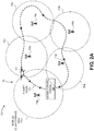
- FIG. 2A illustrates conceptual diagram of an unmanned aerial system (UAS 100), in accordance with one or more embodiments of the present disclosure.
- the network 110 may include a plurality of terrestrial communication nodes 118a-118n (e.g., C2 link towers 118a-118n).
- a UAS controller 102 configured to maintain a C2 link over a UAV 101 of the UAS 100 may be positioned within the ground control station 108. In cases where the UAV 101 travels BVLOS, the UAS controller 102 may be configured to maintain a C2 link with the UAV 101 via the plurality of terrestrial communication nodes 118a-118n.
- the UAS controller 102 may be configured to maintain a C2 link with the UAV 101 by transmitting signals to the UAV 101 via one or more of the terrestrial communication nodes 118a-118n.
- C2 link may be used to refer to a communicative coupling between the UAS controller 102 and the UAV 101 which is sufficient for the UAS controller 102 to transmit command and control signals to the UAV 101 (and/or receive data from the UAV 101) with a selected efficiency or reliability.
- the UAS controller 102 and/or onboard controller 112 may be configured to acquire a command and control (C2) link quality model for a planned route 103 and/or a geographical area covered by a network 110.
- a C2 link quality model may include any model known in the art which is configured to map anticipated C2 link quality metrics (e.g., values) with associated positions along a planned route 103 or within a geographical region.
- the C2 link quality model may include a map, chart, database, or the like, which correlates points along the planned route 103 to C2 link quality values/metrics which are expected to be experienced by a UAV 101 at the respective points along the planned route 103 or within a geographical region.
- a C2 link quality model may include a modeled C2 link coverage area 119 made up of individual modeled C2 link coverage areas 119a-119n associated with each terrestrial communication node 118a-118n.
- the modeled C2 link coverage area 119 may indicate a geographical region within which a UAV 101 is expected to maintain sufficient C2 link connectivity.
- the modeled C2 link coverage area 119 may cover the entirety of the planned route 103, indicating a UAV 101 is expected to maintain sufficient C2 link quality across the entirety of the planned route 103.
- the C2 link quality model may be acquired (e.g., generated, received) via any techniques known in the art.
- the C2 link quality model may also be generated based on any data known in the art including, but not limited to, historical C2 link quality data along the planned route 103, predictive C2 link quality data, anticipated conditions along the planned route 103, and the like.
- the planned route 103 may include a regularly-flown route of the UAS 100.
- UAVs 101 may be configured to regularly fly the planned route 103 in order to inspect railways, electrical lines, trails, roads, landscapes, and the like.
- the UAS controller 102 and/or controller 112 may be configured to monitor C2 link performance along the planned route 103.
- the UAS controller 102 and/or controller 112 may be configured to acquire C2 link quality data during the one or more flights along the planned route 103. Collected C2 link performance data may be stored in memory 106, 116.
- the C2 link quality model may be generated based on historical C2 link quality data along the planned route.
- a UAV 101 may have traveled the planned route 103 ten previous times (e.g., ten previous flights). During each of the ten previous flights, the UAS controller 102 and/or controller 112 may have acquired C2 link quality data along the planned route 103.
- the C2 link quality data acquired during the previous ten flights may be considered historical C2 link quality data.
- the historical C2 link quality data may be used to generate a C2 link quality model. It is noted herein that any mathematical operation(s) known in the art may be used to generate a C2 link quality model from historical C2 link quality data.
- the C2 link quality model may be generated by taking the average and/or median values of historical C2 link quality data at a plurality of points along the planned route 103.
- the C2 link quality model may be generated based on historical C2 link quality data and additional data, such as predictive C2 link quality or anticipated conditions along the planned route 103.
- historical C2 link quality data may be collected/acquired during one or more historical (previous) flights along the planned route 103.
- An initial C2 link quality model may be generated based on the historical C2 link quality data.
- the UAS controller 102 and/or controller 112 may be configured to selectively adjust the initial C2 link quality model based on one or more anticipated conditions for an upcoming monitored flight.
- Anticipated conditions may include, but are not limited to, anticipated noise/interference along the planned route 103, anticipated network traffic along the planned route 103, anticipated weather conditions along the planned route 103, anticipated terrestrial obstructions, anticipated jamming, and the like.
- an initial C2 link quality model may be used as a baseline for an upcoming monitored flight of a UAV 101 along the planned route 103.
- Weather forecasts may anticipate weather conditions which will detrimentally affect C2 link quality during the upcoming monitored flight.
- UAS controller 102 and/or controller 112 may be configured to selectively adjust the initial C2 link quality model based on the anticipated weather conditions in order to generate the C2 link quality model which will be used to predict C2 link quality during the upcoming monitored flight.
- C2 link quality (e.g., C2 link quality model, actual C2 link quality data) may be characterized using any values or characterization techniques known in the art.
- C2 link quality may be characterized based on any number of factors including, but not limited to, received signal strength, packet loss, network delay, latency, and the like.
- C2 link quality may be monitored/characterized by any link quality metrics/characteristics known in the art.
- the UAS controller 102 and/or the onboard controller 112 may be configured to generate one or more alerts if a planned route 103 is planned/programmed which will exceed expected C2 link coverage, as determined by the C2 link quality model. Alerts generated by the UAS controller 102 and/or controller 112 may be transmitted via the network 110, and may be displayed or otherwise conveyed to a user via any notification techniques known in the art. Alerts may include, but are not limited to, text messages, automated phone calls, emails, banners, messages via applications (“Apps”), or the like.
- a C2 link quality model mapping expected C2 link coverage may be generated for a geographical region covered by network 110.
- a planned route 103 for a future flight of a UAV 101 may be input into the UAS 100 (e.g., stored within memory 106, 116).
- the planned route 103 for the future flight may traverse one or more areas which is not expected to exhibit C2 link coverage (e.g., traverses areas outside of the C2 link quality model).
- the UAS controller 102 and/or controller 112 may be configured to generate one or more alerts configured to alert a user that the planned route 103 for the future flight is not expected to maintain sufficient C2 link coverage across the entirety of the planned route.
- the UAS controller 102 and/or controller 112 may be configured to generate one or more alerts configured to alert a user that the planned route 103 for the future flight is not expected to maintain sufficient C2 link coverage across the entirety of the planned route.
- users may be able to adjust the planned route 103 and/or reevaluate characteristics of the future flight in order to ensure safe, efficient operation of the UAV 101. Accordingly, it is contemplated herein that comparing C2 link quality models and planned routes 103 prior to the flights along the planned routes may enable safer, more efficient planning decisions.
- the UAS controller 102 and/or onboard controller 112 may be configured to generate one or more control signals configured to cause the UAV 101 to perform a monitored flight along a planned route 103.
- the one or more control signals may be transmitted from the UAS controller 102 (e.g., base station 108) to the UAV 101 via the network 110.
- predicted/anticipated C2 link quality during the monitored route may be modeled by the C2 link quality model.
- the UAS controller 102 and/or onboard controller 112 may be configured to acquire actual C2 link quality data during the monitored flight along the planned route 103.
- the UAS controller 102 and/or controller 112 may be configured to monitor/record actual C2 link quality experienced.
- the UAS controller 102 and/or controller 112 may be configured to acquire actual C2 link quality data by identifying a C2 link quality metric at regular or irregular intervals during the monitored flight, and associating the identified C2 link quality metrics with the position of the UAV 101 along the planned route where each of the respective C2 link quality metrics were identified.
- Actual C2 link quality data may be acquired in real time or near-real time, and may be stored in memory 106, 116.
- the UAS controller 102 and/or onboard controller 112 may be configured to compare the actual C2 link quality data to the C2 link quality model.
- the C2 link quality model and actual C2 link quality data may both be stored in memory 106, 116.
- the UAS controller 102 and/or onboard controller 112 may be configured to compare the C2 link quality model and actual C2 link quality data by comparing C2 link quality values/metrics at similar locations along the planned route 103.
- C2 link performance may be monitored for the purpose of C2 link integrity monitoring, which may provide computing logic awareness of the current status of the C2 link connection. Accordingly, it is contemplated herein that actual C2 link quality data may be compared to the C2 link quality model in real time and/or near-real time.
- the UAS controller 102 and/or onboard controller 112 may be configured to determine a first C2 link quality value ( C2 LQ 1 ) for an identified location based on the C2 link quality model, and determine a second C2 link quality value ( C2 LQ 2 ) for the identified location based on the actual C2 link quality data.
- the UAS controller 102 and/or onboard controller 112 may be able to compare expected or anticipated C2 link quality (C2 link quality model) to the C2 link quality data actually experienced by the UAV 101 during the monitored flight.
- the UAS controller 102 and/or onboard controller 112 may be configured to selectively modify one or more characteristics of the C2 link quality model based on actual C2 link quality data acquired during the monitored flight. For example, if the actual C2 link quality data acquired during the monitored flight is better than expected, the UAS controller 102 and/or onboard controller 112 may be configured to selectively modify one or more characteristics of the C2 link quality model to reflect the improved C2 link quality experienced by the UAV 101.
- the UAS controller 102 and/or onboard controller 112 may be configured to identify a C2 link quality deviation between the actual C2 link quality data and the C2 link quality model. For example, continuing with reference to the example above, the UAS controller 102 and/or onboard controller 112 may be configured to determine a first C2 link quality value ( C2 LQ 1 ) for an identified location based on the C2 link quality model, and determine a second C2 link quality value ( C2 LQ 2 ) for the identified location based on the actual C2 link quality data.
- C2 link quality value C2 LQ 1
- C2 LQ 2 second C2 link quality value
- a C2 link quality deviation may exist when the first C2 link quality value ( C2 LQ 1 from the C2 link quality model) is not equal to the second C2 link quality value ( C2 LQ 2 from the actual C2 link quality data).
- the UAS controller 102 and/or onboard controller 112 may be configured to compare the identified C2 link quality deviation ( ⁇ C2 LQ ) to a threshold deviation value ( C2 thresh ) .
- the threshold deviation value ( C2 thresh ) may be characterized by any number of link connectivity metrics or characteristics known in the art including, but not limited to, received signal strength, packet loss, network delay, latency, and the like.
- the C2 link quality model and actual C2 link quality data may be characterized by received signal strength values.
- the threshold deviation value ( C2 thresh ) may include a received signal strength value such that the identified C2 link quality deviation ( ⁇ C2 LQ ) (expressed as a received signal strength value) may be compared to the threshold deviation value ( C2 thresh ) (expressed as a received signal strength value).
- the UAS controller 102 and/or controller 112 may be configured to generate an alert configured to alert a user of the identified C2 link quality deviation ( ⁇ C2 LQ ) . It is contemplated herein that providing alerts to a user operating the UAV 101 may enable safer, more intuitive operation of the UAV 101. In particular, by receiving an alert prior to total loss of C2 connectivity, a user may be able to make decisions as to how the UAV 101 may be safely and effectively operated without losing C2 link connectivity.
- Alerts generated by the UAS controller 102 and/or controller 112 may be transmitted via the network 110, and may be displayed or otherwise conveyed to a user via any notification techniques known in the art. Alerts may include, but are not limited to, text messages, automated phone calls, emails, banners, messages via applications (“Apps”), or the like.
- the UAS controller 102 and/or onboard controller 112 may be configured to adaptively modify one or more characteristics of the planned route 103 based on the identified C2 link quality deviation ( ⁇ C2 LQ ) .
- Characteristics of the planned route 103 may include, but are not limited to, a direction/heading along the planned route 103, an altitude of the UAV 101 along the planned route 103, a speed of the UAV 101 along the planned route 103, and the like.
- the threshold deviation value ( C2 thresh ) may be used as a reference point to determine acceptable deviations from anticipated C2 link quality such that flight along the planned route is still safe and controlled.
- the threshold deviation value ( C2 thresh ) may be regarded as a design choice within the UAS 100 to select tolerances for C2 link quality.
- the threshold deviation value ( C2 thresh ) may be directly proportional to the tolerance within the UAS 100. For example, increasing the threshold deviation value ( C2 thresh ) may increase the tolerance within the UAS 100, thereby allowing higher deviations between actual C2 link quality data and the C2 link quality model. Conversely, by way of another example, decreasing the threshold deviation value ( C2 thresh ) may decrease the tolerance within the UAS 100, thereby allowing lower deviations between actual C2 link quality data and the C2 link quality model.
- the threshold deviation value ( C2 thresh ) may be selectively adjusted automatically and/or manually based on preferred characteristics of the UAS 100.
- the UAS controller 102 and/or onboard controller 112 may be configured to generate one or more control signals configured to cause the UAV 101 to perform one or more prescribed flight plan maneuvers if the identified C2 link quality deviation ( ⁇ C2 LQ ) exceeds the threshold deviation value ( C2 thresh ) (e.g., ⁇ C2 LQ > C2 thresh ) .
- the threshold deviation value C2 thresh
- Several conditions may exist which may cause an identified C2 link quality deviation ( ⁇ C2 LQ ) to exceed the threshold deviation value ( C2 thresh ) ( ⁇ C2 LQ > C2 thresh ) .
- conditions which may cause ⁇ C2 LQ > C2 thresh may include, but are not limited to, inaccurate modeling within the C2 link quality model, network faults, weather conditions, interference, jamming, high network traffic, and the like.
- the UAS controller 102 and/or onboard controller 112 may be configured to determine that the actual (experienced) C2 link quality is not within the allowable tolerance for the UAS 100. This may be indicative that actual experienced C2 link quality is substantially less than what was expected according to the C2 link quality model.
- the UAS controller 102 and/or onboard controller 112 may be configured to generate one or more control signals configured to cause the UAV 101 to perform one or more prescribed flight plan maneuvers in order to prevent total loss of C2 link connectivity and ensure safe flights within the UAS 100.
- the UAS controller 102 and/or onboard controller 112 may acquire actual C2 link quality data, and compare the actual C2 link quality data to a C2 link quality model. High data traffic, weather conditions, or some other factors experienced along the planned route 103 may result in a significantly decreased C2 link quality.
- the UAS controller 102 and/or onboard controller 112 may identify that a C2 link quality deviation ( ⁇ C2 LQ ) exceeds the threshold deviation value ( C2 thresh ) (e.g., ( ⁇ C2 LQ > C2 thresh ) .
- the UAS controller 102 and/or onboard controller 112 may be configured to generate one or more control signals configured to cause the UAV 101 to perform one or more prescribed flight plan maneuvers.
- the one or more prescribed flight plan maneuvers may be configured to prevent total loss of C2 link connectivity between the UAS controller 102 and the UAV 101.
- the one or more prescribed flight plan maneuvers may be executed prior to the total loss of C2 link connectivity between the UAS controller 102 and the UAV 101.
- the one or more prescribed flight plan maneuvers may include any flight maneuvers known in the art including, but not limited to, a backtracking maneuver (e.g., backtrack along planned route 103), a homing maneuver (e.g., return to ground control station 108), a hover-and-hold maneuver, a climb-and-hold maneuver, and the like.
- Program instructions for the prescribed flight plan maneuvers may be stored in memory 106, 116.
- the UAS 100 may be configured to prevent the UAV 101 from being inadvertently programmed or instructed to exceed the predicted boundaries of C2 link coverage and positive C2 control (as determined by the C2 link quality model).
- the UAS 100 may be configured to cause the UAV 101 to continue along the planned route 103 if C2 link quality subsequently improves to within acceptable tolerances. For example, after identifying insufficient actual C2 link quality data such that ⁇ C2 LQ > C2 thresh , the UAS controller 102 and/or onboard controller 112 may cause the UAV 101 to perform a hover-and-hold maneuver so as to prevent total C2 link connectivity loss. Subsequently, at a time subsequent to performing the hover-and-hold maneuver, C2 link quality may improve.
- the UAS controller 102 and/or onboard controller 112 may determine that ⁇ C2 LQ ⁇ C2 thresh , and that C2 link quality has improved to within acceptable tolerances. Accordingly, the UAS controller 102 and/or onboard controller 112 may then transmit one or more control signals to the UAV 101, wherein the one or more control signals are configured to cause the UAV 101 to terminate the hover-and-hold maneuver and continue along the planned route 103.
- FIG. 2B illustrates conceptual diagram of an unmanned aerial system (UAS), in accordance with one or more embodiments of the present disclosure.
- the UAS 100 may include one or more UAVs 101a-101n.
- embodiments of the present disclosure may enable safer, coordinated UAV 101 control across a plurality of UAVs 101.
- embodiments of the present disclosure may enable more efficient resource management, and may provide means to selectively adjust characteristics of the UAS 100 based on resource consumption.
- the UAS 100 may include a plurality of UAVs 101a, 101b, 101c.
- Each of the UAVs 101a, 101b, 101c may be communicatively coupled to one or more UAS controllers 102.
- a UAS controller 102 may be communicatively coupled to the UAVs 101a, 101b, 101c in order to maintain C2 link connectivity with each of the UAVs 101a, 101b, 101c.
- the UAV 101a may be configured to perform a monitored flight along the planned route 103.
- the actual C2 link coverage area 121a, 121b, 121 d, and 121e may substantially conform to the modeled C2 link coverage area 119a, 119b, 119d, and 119e.
- increased network traffic around terrestrial communication node 118c may cause an actual C2 link coverage area 121c to be substantially smaller than the modeled C2 link coverage area 119c. Accordingly, there may not be sufficient C2 link coverage for the entirety of the planned route 103.
- the UAS controller 102 and/or controller 112 may be configured to identifying insufficient actual C2 link quality data such that ⁇ C2 LQ > C2 thresh before departing the actual C2 link coverage area 121d. Accordingly, the UAS controller 102 and/or controller 112 may be configured to cause the UAV 101a to execute one or more prescribed flight plan maneuvers in order to retain C2 link connectivity prior to departing the actual C2 link coverage area 121b.
- the UAS controller 102 and/or controller 112 may be configured to modify one or more characteristics of the UAVs 101b, 101c in an attempt to restore sufficient C2 link connectivity along the planned route 103 of the UAV 101a.
- the UAS controller 102 and/or controller 112 may be configured to transmit one or more control signals to the UAV 101b and/or UAV 101c in response to the identified C2 link quality deviation ( ⁇ C2 LQ ) , wherein the one or more control signals are configured to cause the UAV 101b and/or UAV 101c to selectively adjust one or more characteristics of the UAV 101b and/or UAV 101c based on the identified C2 link quality deviation ( ⁇ C2 LQ ) .
- Characteristics of the of the UAVs 101b, 101c which may be selectively adjusted may include, but are not limited to, a position of the UAVs 101b, 101c c, a planned route of the UAVs 101b, 101c c, and the like. For instance, by causing the UAV 102b to move away from the terrestrial communication node 118c, the UAS 100 may be configured to reduce network traffic across the terrestrial communication node 118c in order to increase the size of the actual C2 link coverage area 121c and restore sufficient C2 link connectivity across the planned route 103.
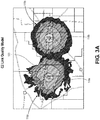
- FIG. 3A-3B are a graphical illustrations of C2 link quality of an unmanned aerial system (UAS 100), in accordance with one or more embodiments of the present disclosure.
- UAS 100 unmanned aerial system
- FIG. 3A illustrates a planned route 103 traversing through modeled C2 link coverage areas 119a, 119b of a first and second terrestrial communication node 118a, 118b.
- a modeled C2 link coverage area 119 for a planned route 103 may be made up of several individual modeled C2 link coverage areas 119a, 119b associated with individual terrestrial communication nodes 118a, 118b. Furthermore, the modeled C2 link coverage area 119 may be irregular in shape.
- the modeled C2 link coverage area 119 may denote an area within which a UAV 101 is expected to maintain sufficient C2 link connectivity. However, the C2 link quality within the modeled C2 link coverage area 119 may still vary as a UAV 101 travels along the planned route 103. For example, when traveling the planned route 103 from left to right in FIG. 3A , a UAV 101 may be expected to experience high C2 link quality when flying proximate to the first terrestrial communication node 118a. Subsequently, when flying the planned route between the first and second terrestrial communication nodes 118a, 118b, the C2 link quality may be expected to decrease, and subsequently increase again when flying proximate to the first terrestrial communication node 118b. In this regard, it may be appreciated that C2 link quality may rise and fall even within a modeled C2 link coverage area 119.
- actual C2 link coverage areas 121 may not exactly map to modeled C2 link coverage areas 119.
- Conditions which may cause an actual C2 link coverage area 121 to differ from a modeled C2 link coverage areas 119 may include, but are not limited to, inaccurate modeling within the C2 link quality model, network faults, weather conditions, interference, jamming, high network traffic, and the like.
- weather conditions, network traffic, or the like may cause the actual C2 link coverage area 121b to be substantially smaller than the modeled C2 link coverage area 119b.
- the UAS controller 102 and/or controller 112 may be configured to determine that less than expected C2 link quality values, and cause a UAV 101 flying along the planned route 103 to perform one or more prescribed flight plan maneuvers in order to prevent total C2 link connectivity loss.
- the UAS controller 102 and/or controller 112 may be configured to cause a UAV 101 flying along the planned route 103 to perform one or more prescribed flight plan maneuvers proximate to point 123, prior to leaving the actual C2 link coverage area 121a.
- C2 link models and/or C2 link coverage areas may be applied to a plurality of UAVs 101, a range of planned routes 103, and the like.
- hardware and performance variabilities may result in increased differences between C2 link coverage areas 121 may not exactly map to modeled C2 link coverage areas 119.
- C2 link models and/or C2 link coverage areas 119 may be generated for a specific platform.
- a C2 link model and/or C2 link coverage area 119 may be generated for a specific UAV 101 flying a specific planned route 103 using a specific network 110.
- embodiments of the present disclosure may enable safer, more responsible beyond visual line of sight (BVLOS) operations of UAVs 101.
- the UAS 100 of the present disclosure may prevent UAVs 101 from exceeding boundaries of positive C2 control.
- embodiments of the present disclosure may enable more sophisticated, safe, and reliable unmanned aerial systems.
- the UAS 100 of the present disclosure may provide a robust, controlled safety net for future UAS flight authorization.
- the one or more processors 104, 114 may include any one or more processing elements known in the art. In this sense, the one or more processors 104, 114may include any microprocessor-type device configured to execute software algorithms and/or instructions. It should be recognized that the steps described throughout the present disclosure may be carried out by a single computer system or, alternatively, multiple computer systems. Furthermore, it should be recognized that the steps described throughout the present disclosure may be carried out on any one or more of the one or more processors 104, 114. In general, the term "processor" may be broadly defined to encompass any device having one or more processing elements, which execute program instructions from memory 106, 116.
- UAS controller 102 may include processor or logic elements suitable for carrying out at least a portion of the steps described throughout the present disclosure. Therefore, the above description should not be interpreted as a limitation on the present disclosure but merely an illustration.
- the memory 106, 116 may include any storage medium known in the art suitable for storing program instructions executable by the associated one or more processors 104, 114 and the data generated/received by UAS 100.
- the memory 106, 116 may include a non-transitory memory medium.
- the memory 106, 116 may include, but is not limited to, a read-only memory (ROM), a random-access memory (RAM), a magnetic or optical memory device (e.g., disk), a magnetic tape, a solid-state drive and the like.
- the memory 106, 116 is configured to store data including, but not limited to, C2 link quality models, acquired actual C2 link quality data, and the like.
- memory 106, 116 may be housed in a common controller housing with the one or more processors 104, 114. In an alternative embodiment, the memory 106, 116 may be located remotely with respect to the physical location of the processors 104, 114, UAS controller 102, controller 112, and the like. In another embodiment, the memory 106, 116 maintains program instructions for causing the one or more processors 104, 114 to carry out the various steps described through the present disclosure.
- FIG. 4 illustrates a flowchart of a method 400 for operating an unmanned aerial vehicle (UAV 101), in accordance with one or more embodiments of the present disclosure. It is noted herein that the steps of method 400 may be implemented all or in part by UAS 100. It is further recognized, however, that the method 400 is not limited to the UAS 100 in that additional or alternative system-level embodiments may carry out all or part of the steps of method 400.
- a command and control (C2) link quality model is generated for a planned route and/or a geographical region.
- a C2 link quality model may be generated for a planned route 103.
- a C2 link quality model may be generated for a geographical region.
- the C2 link quality model may include a modeled C2 link coverage area 119.
- a C2 link quality model may include any model known in the art which is configured to map anticipated C2 link quality metrics (e.g., values) with associated positions along a planned route 103.
- the C2 link quality model may include a map, chart, database, or the like, which correlates points along the planned route 103 to C2 link quality values/metrics which are expected to be experienced by a UAV 101 at the respective points along the planned route 101.
- actual C2 link quality data is acquired during a monitored flight of the UAV along the planned route.
- the UAS controller 102 and/or controller 112 may monitor and acquire actual C2 link quality data experienced by the UAV 101.
- Actual C2 link quality data may be acquired in real time or near-real time.
- the actual C2 link quality data is compared to the C2 link quality model.
- the C2 link quality model and actual C2 link quality data may both be stored in memory 106, 116.
- the UAS controller 102 and/or onboard controller 112 may be configured to compare the C2 link quality model and actual C2 link quality data by comparing C2 link quality values/metrics at similar locations along the planned route 103.
- C2 link performance may be monitored for the purpose of C2 link integrity monitoring, which may provide computing logic awareness of the current status of the C2 link connection.
- a C2 link quality deviation between the actual C2 link quality data and the C2 link quality model is identified.
- the UAS controller 102 and/or onboard controller 112 may be configured to determine a first C2 link quality value ( C2 LQ 1 ) for an identified location based on the C2 link quality model, and determine a second C2 link quality value ( C2 LQ 2 ) for the identified location based on the actual C2 link quality data.
- a C2 link quality deviation may exist when the first C2 link quality value ( C2 LQ 1 from the C2 link quality model) and the second C2 link quality value ( C2 LQ 2 from the actual C2 link quality data) are not equal.
- one or more prescribed flight plan maneuvers are performed if the identified C2 link quality deviation exceeds a threshold deviation value (e.g., ⁇ C2 LQ > C2 thresh ) .
- a threshold deviation value e.g., ⁇ C2 LQ > C2 thresh
- the UAS controller 102 and/or onboard controller 112 may acquire actual C2 link quality data, and compare the actual C2 link quality data to a C2 link quality model.
- the UAS controller 102 and/or onboard controller 112 may identify that a C2 link quality deviation ( ⁇ C2 LQ ) exceeds the threshold deviation value ( C2 thresh ) (e.g., ( ⁇ C2 LQ > C2 thresh ) .
- the UAS controller 102 and/or onboard controller 112 may be configured to generate one or more control signals configured to cause the UAV 101 to perform one or more prescribed flight plan maneuvers.
- the one or more prescribed flight plan maneuvers may be configured to prevent total loss of C2 link connectivity between the UAS controller 102 and the UAV 101.
- the one or more prescribed flight plan maneuvers may be executed prior to the total loss of C2 link connectivity between the UAS controller 102 and the UAV 101.
- the one or more prescribed flight plan maneuvers may include any flight maneuvers known in the art including, but not limited to, a backtracking maneuver (e.g., backtrack along planned route 103), a homing maneuver (e.g., return to ground control station 108), a hover-and-hold maneuver, a climb-and-hold maneuver, and the like.
- embodiments of the methods disclosed herein may include one or more of the steps described herein. Further, such steps may be carried out in any desired order and two or more of the steps may be carried out simultaneously with one another. Two or more of the steps disclosed herein may be combined in a single step, and in some embodiments, one or more of the steps may be carried out as two or more sub-steps. Further, other steps or sub-steps may be carried in addition to, or as substitutes to one or more of the steps disclosed herein.
Landscapes
- Engineering & Computer Science (AREA)
- Aviation & Aerospace Engineering (AREA)
- Physics & Mathematics (AREA)
- General Physics & Mathematics (AREA)
- Remote Sensing (AREA)
- Radar, Positioning & Navigation (AREA)
- Automation & Control Theory (AREA)
- Mechanical Engineering (AREA)
- Computer Networks & Wireless Communication (AREA)
- Signal Processing (AREA)
- Control Of Position, Course, Altitude, Or Attitude Of Moving Bodies (AREA)
- Traffic Control Systems (AREA)
Abstract
Description
- Operating unmanned aerial vehicles (UAVs) beyond visual line of sight (BVLOS) requires robust command and control (C2) data links with the UAVs in order to ensure positive control of the UAVs. Maintaining a C2 link in an unmanned aerial system (UAS) is critical to mission success, aircraft safety, and community safety. The ever-increasing use of drones and other UAVs amplifies the need to prevent loss of C2 links in order to ensure safe operation of the UAVs, prevent property damage, and prevent human injury. Current UAS systems utilize methods which trigger UAVs to perform prescribed maneuvers (e.g., pre-programmed flight plans) after a C2 link has been lost. However, these prescribed maneuvers only take place after total loss of the C2 link. Therefore, it would be desirable to provide a system and method which cure one or more of the shortfalls of the previous approaches identified above.
- An unmanned aerial system (UAS) is disclosed. In embodiments, the UAS includes an unmanned aerial vehicle (UAV), and a controller communicatively coupled to the UAV. In embodiments, the UAS controller may be configured to: acquire a command and control (C2) link quality model for a planned route; generate one or more control signals configured to cause the UAV to perform a monitored flight along a planned route; acquire actual C2 link quality data during the monitored flight along the planned route; compare the actual C2 link quality data to the C2 link quality model; identify a C2 link quality deviation between the actual C2 link quality and the C2 link quality model; and generate one or more control signals configured to cause the UAV to perform one or more prescribed flight plan maneuvers if the identified C2 link quality deviation (ΔC2LQ ) exceeds a threshold deviation value (C2thresh ).
- In some embodiments of the unmanned aerial system, the controller is positioned onboard the UAV.
- In some embodiments of the UAS, the controller includes a remote UAS controller wirelessly coupled to the UAV.
- In some embodiments of the UAS, the one or more prescribed flight plan maneuvers are performed in order to prevent total loss of C2 link connectivity between the UAV and the UAS controller.
- In some embodiments of the UAS, the C2 link quality model includes a plurality of anticipated C2 link quality metrics associated with a plurality of positions along the planned route.
- In some embodiments of the UAS, acquiring a command and control (C2) link quality model for a planned route includes generating the C2 link quality model based on historical C2 link quality data along the planned route.
- In some embodiments of the UAS, acquiring a C2 link quality model based on historical C2 link quality data along the planned route includes: performing one or more flights along the planned route; acquiring actual C2 link quality data during the one or more flights along the planned route; and generating the C2 link quality model based on the acquired actual C2 link quality data.
- In some embodiments of the UAS, acquiring a C2 link quality model for a planned route further includes: collecting the historical C2 link quality data along the planned route; generating an initial C2 link quality model based on the historical C2 link quality data; and selectively adjusting the initial C2 link quality model based on one or more anticipated conditions during the monitored flight to generate the C2 link quality model. In embodiments, the one or more anticipated conditions may include noise along the planned route, traffic along the planned route, or weather conditions along the planned route.
- In some embodiments of the UAS, the one or more prescribed flight plan maneuvers include at least one of a backtracking maneuver, a homing maneuver, or a hover-and-hold maneuver.
- In some embodiments of the UAS, the one or more prescribed flight plan maneuvers include a hover-and-hold maneuver, and the UAS controller is further configured to:
- determine, at a time subsequent to performing the hover-and-hold maneuver, that the identified C2 link quality deviation (ΔC2LQ ) is less than the threshold deviation value (C2thresh );
- and transmit one or more control signals to the UAV, the one or more control signals configured to cause the UAV to terminate the hover-and-hold maneuver and continue along the planned route.
- In some embodiments of the UAS, the UAS controller is further configured to adaptively modify one or more characteristics of the planned route based on the identified C2 link quality deviation (ΔC2LQ ).
- In some embodiments of the UAS, the UAS further includes at least one additional UAV communicatively coupled to the UAS controller.
- In some embodiments of the UAS, wherein the UAS controller is further configured to: transmit one or more control signals to the at least one additional UAV in response to the identified C2 link quality deviation (ΔC2LQ ), wherein the one or more control signals are configured to cause the at least one additional UAV to selectively adjust one or more characteristics of the at least one additional UAV based on the identified C2 link quality deviation (ΔC2LQ ).
- In some embodiments of the UAS, the one or more characteristics of the at least one additional UAV include at least one of a position of the at least one additional UAV or a planned route of the at least one additional UAV.
- A method of operating an unmanned aerial vehicle (UAV) is disclosed. In embodiments, the method includes: generating a command and control (C2) link quality model for a planned route; acquiring actual C2 link quality data during a monitored flight of the UAV along the planned route; comparing the actual C2 link quality data to the C2 link quality model; identifying a C2 link quality deviation (ΔC2LQ ) between the actual C2 link quality data and the C2 link quality model; and performing one or more prescribed flight plan maneuvers if the identified C2 link quality deviation (ΔC2LQ ) exceeds a threshold deviation value (C2thresh ).
- This Summary is provided solely as an introduction to subject matter that is fully described in the Detailed Description and Drawings. The Summary should not be considered to describe essential features nor be used to determine the scope of the Claims. Moreover, it is to be understood that both the foregoing Summary and the following Detailed Description are provided for example and explanatory only and are not necessarily restrictive of the subject matter claimed.
- The detailed description is described with reference to the accompanying figures. The use of the same reference numbers in different instances in the description and the figures may indicate similar or identical items. Various embodiments or examples ("examples") of the present disclosure are disclosed in the following detailed description and the accompanying drawings. The drawings are not necessarily to scale. In general, operations of disclosed processes may be performed in an arbitrary order, unless otherwise provided in the claims. In the drawings:
-
FIG. 1 illustrates a simplified block diagram view of an unmanned aerial system (UAS), in accordance with one or more embodiments of the present disclosure. -
FIG. 2A illustrates a conceptual diagram of an unmanned aerial system (UAS), in accordance with one or more embodiments of the present disclosure. -
FIG. 2B illustrates a conceptual diagram of an unmanned aerial system (UAS), in accordance with one or more embodiments of the present disclosure. -
FIG. 3A is a graphical illustration of C2 link quality of an unmanned aerial system (UAS), in accordance with one or more embodiments of the present disclosure. -
FIG. 3B is a graphical illustration of C2 link quality of an unmanned aerial system (UAS), in accordance with one or more embodiments of the present disclosure. -
FIG. 4 illustrates a flowchart of a method for operating an unmanned aerial vehicle (UAV), in accordance with one or more embodiments of the present disclosure. - Before explaining one or more embodiments of the disclosure in detail, it is to be understood that the embodiments are not limited in their application to the details of construction and the arrangement of the components or steps or methodologies set forth in the following description or illustrated in the drawings. In the following detailed description of embodiments, numerous specific details may be set forth in order to provide a more thorough understanding of the disclosure. However, it will be apparent to one of ordinary skill in the art having the benefit of the instant disclosure that the embodiments disclosed herein may be practiced without some of these specific details. In other instances, well-known features may not be described in detail to avoid unnecessarily complicating the instant disclosure.
- As used herein a letter following a reference numeral is intended to reference an embodiment of the feature or element that may be similar, but not necessarily identical, to a previously described element or feature bearing the same reference numeral (e.g., 1, 1a, 1b). Such shorthand notations are used for purposes of convenience only and should not be construed to limit the disclosure in any way unless expressly stated to the contrary.
- Further, unless expressly stated to the contrary, "or" refers to an inclusive or and not to an exclusive or. For example, a condition A or B is satisfied by anyone of the following: A is true (or present) and B is false (or not present), A is false (or not present) and B is true (or present), and both A and B are true (or present).
- In addition, use of "a" or "an" may be employed to describe elements and components of embodiments disclosed herein. This is done merely for convenience and "a" and "an" are intended to include "one" or "at least one," and the singular also includes the plural unless it is obvious that it is meant otherwise.
- Finally, as used herein any reference to "one embodiment" or "some embodiments" means that a particular element, feature, structure, or characteristic described in connection with the embodiment is included in at least one embodiment disclosed herein. The appearances of the phrase "in some embodiments" in various places in the specification are not necessarily all referring to the same embodiment, and embodiments may include one or more of the features expressly described or inherently present herein, or any combination of sub-combination of two or more such features, along with any other features which may not necessarily be expressly described or inherently present in the instant disclosure.
- Operating unmanned aerial vehicles (UAVs) beyond visual line of sight (BVLOS) requires robust command and control (C2) data links with the UAVs in order to ensure positive control of the UAVs. Maintaining a C2 link in an unmanned aerial system (UAS) is critical to mission success, aircraft safety, and community safety. The ever-increasing use of drones and other UAVs amplifies the need to prevent loss of C2 links in order to ensure safe operation of the UAVs, prevent property damage, and prevent human injury.
- Current UAS systems are able to monitor C2 link quality during flights, and utilize methods which trigger UAVs to perform prescribed maneuvers (e.g., pre-programmed flight plans) after a C2 link has been lost. However, these prescribed maneuvers (e.g., return to home base) are typically performed without regard to re-gaining and/or maintaining a C2 link, and only take place after total loss of the C2 link. Furthermore, current UAS systems are not able to prevent a UAV from unintentionally departing an area of known sufficient C2 link coverage. Accordingly, current UAS systems are able to take measures after complete loss of a C2 link, but are unable to prevent the loss of the C2 link in the first place.
- Accordingly, embodiments of the present disclosure are directed to a system and method which cure one or more of the shortfalls of the previous approaches identified above. Embodiments of the present disclosure are directed to an unmanned aerial system (UAS) which is configured to determine expected C2 link coverage for UAVs, and prevent UAVs from departing from areas of expected and sufficient C2 link coverage. More particularly, embodiments of the present disclosure are directed to a UAS and related method for determining expected C2 link quality model, and comparing actual C2 link quality to the expected C2 link quality model to prevent loss of C2 link connectivity. Additional embodiments of the present disclosure are directed to a system and method for performing prescribed flight plan maneuvers in order to prevent loss of C2 link connectivity.
- It is contemplated herein that embodiments of the present disclosure may enable safer, more responsible beyond visual line of sight (BVLOS) operations of UAVs. By preventing C2 link loss, embodiments of the present disclosure may enable more sophisticated, safe, and reliable unmanned aerial systems.
-
FIG. 1 illustrates a simplified block diagram view of an unmanned aerial system (UAS 100), in accordance with one or more embodiments of the present disclosure. TheUAS 100 may include, but is not limited to, aUAS controller 102, anetwork 110, and one or more unmanned aerial vehicles (UAVs 101). - In embodiments, the
UAS 100 may include aUAS controller 102 communicatively coupled to one ormore UAVs 101 via anetwork 110. In embodiments, theUAS controller 102 may be positioned remotely with respect to the one ormore UAVs 101. For example, as shown inFIG. 1 , theUAS controller 102 may be positioned within aground control station 108 such that theUAS controller 102 is wirelessly communicatively coupled to the one ormore UAVs 101 via thenetwork 110. It is noted herein, however, theground control station 108 is provided solely for illustrative purposes, and is not to be regarded as a limitation of the present disclosure, unless noted otherwise herein. In this regard, it is contemplated herein that theUAS controller 102 may be positioned within anyground control station 108, operation center, mobile control station, airborne control station, or the like. By way of another example, theUAS controller 102 may include a mobile device including, but not limited to, hand-held user interface, tablet, smart phone, and the like. - The
UAS controller 102 may include one ormore processors 104 and amemory 106. The one ormore processors 104 may be configured to execute a set of program instructions stored inmemory 106, the set of program instructions configured to cause the one ormore processors 104 to carry out various steps/functions of the present disclosure. For example, as will be described in further detail herein, the one ormore processors 104 of theUAS controller 102 may be configured to maintain command and control (C2) over the one ormore UAVs 101. In this regard, one ormore processors 104 of theUAS controller 102 may be configured to generate one or more control signals configured to cause theUAVs 101 to perform various tasks, functions, and/or prescribed flight plan maneuvers. - The
UAS controller 102 may be communicatively coupled to the one ormore UAVs 101 in any manner known in the art. For example, theUAS controller 102 may be directly coupled to theUAVs 101 such that signals may be transmitted directly between theUAVs 101 and theUAS controller 102. By way of another example, theUAS controller 102 may be communicatively coupled to the one ormore UAVs 101 via anetwork 110. In embodiments where theUAS 100 includes anetwork 110, theUAS controller 102 andUAVs 101 may each include network interface circuitry configured to interface with thenetwork 110. As will be described in further detail herein, thenetwork 110 may include anynetwork 110 known in the art. For example, thenetwork 110 may include, but is not limited to, a network of terrestrial communication nodes (e.g., communication towers), a network of mobile communication nodes (e.g., mobile terrestrial communication nodes, mobile airborne communication nodes), and the like. - It is further noted herein that the
UAS controller 102 andUAVs 101 may be directly and/or indirectly (via network 110) communicatively coupled to one another via any communication protocols known in the art including, but not limited to, GSM, GPRS, CDMA, EV-DO, EDGE, WiMAX, 3G, 4G, 4G LTE, 5G, WiFi protocols, radio frequency (RF), LoRa, and the like. For example, theUAS controller 102 andUAVs 101 may transmit data between each other, directly and/or vianetwork 110, utilizing the L-band or C-band. For instance, theUAS 100 may transmit data between the various component of theUAS 100 utilizing signals in the range of 450 mHz-5 GHz. It is noted herein that signals transmitted withinUAS 100 may utilize any frequency or range of frequencies known in the art. - The one or
more UAVs 101 may include any unmanned aerial vehicle known in the art including, but not limited to, civilian drones, commercial drones, military drones, transport drones, and the like. In embodiments, theUAVs 101 may include acontroller 112. Thecontroller 112 of theUAV 101 may include one ormore processors 114 and amemory 116. The one ormore processors 114 may be configured to execute a set of program instructions stored inmemory 116, the set of program instructions configured to cause the one ormore processors 114 to carry out various steps/functions of the present disclosure. For example, thecontroller 112 may be configured to receive control commands from theUAS controller 102, and perform one or more tasks, functions, or flight maneuvers in response to the received control commands. - It is noted herein that various steps/functions of the present disclosure may be performed by the
UAS controller 102 and/or thecontroller 112, unless noted otherwise herein. In this regard, various steps/functions carried out within theUAS 100 may be agnostic with respect to the physical location that those steps/functions are carried out, unless noted otherwise herein. Accordingly, various steps/functions carried out by theUAS 100 may be generally described as being carried out by theUAS controller 102 and/orcontroller 112. - As noted previously herein, the
UAS controller 102/controller 112 may include one ormore processors memory more processors memory more processors UAS controller 102/controller 112 may be configured to: acquire a command and control (C2) link quality model for a planned route; generate one or more control signals configured to cause the UAV to perform a monitored flight along a planned route; acquire actual C2 link quality data during the monitored flight along the planned route; compare the actual C2 link quality data to the C2 link quality model; identify a C2 link quality deviation between the actual C2 link quality data and the C2 link quality model; and generate one or more control signals configured to cause the UAV to perform one or more prescribed flight plan maneuvers if the identified C2 link quality deviation exceeds a threshold deviation value. Each of these steps/functions will be addressed in turn. -
FIG. 2A illustrates conceptual diagram of an unmanned aerial system (UAS 100), in accordance with one or more embodiments of the present disclosure. - As shown in
FIG. 2A , in some embodiments, thenetwork 110 may include a plurality ofterrestrial communication nodes 118a-118n (e.g.,C2 link towers 118a-118n). AUAS controller 102 configured to maintain a C2 link over aUAV 101 of theUAS 100 may be positioned within theground control station 108. In cases where theUAV 101 travels BVLOS, theUAS controller 102 may be configured to maintain a C2 link with theUAV 101 via the plurality ofterrestrial communication nodes 118a-118n. In this regard, as theUAV 101 travels along aplanned route 103, theUAS controller 102 may be configured to maintain a C2 link with theUAV 101 by transmitting signals to theUAV 101 via one or more of theterrestrial communication nodes 118a-118n. - For the purposes of the present disclosure, the term "C2 link," "C2 link connectivity," and like terms, may be used to refer to a communicative coupling between the
UAS controller 102 and theUAV 101 which is sufficient for theUAS controller 102 to transmit command and control signals to the UAV 101 (and/or receive data from the UAV 101) with a selected efficiency or reliability. - In embodiments, the
UAS controller 102 and/oronboard controller 112 may be configured to acquire a command and control (C2) link quality model for aplanned route 103 and/or a geographical area covered by anetwork 110. A C2 link quality model may include any model known in the art which is configured to map anticipated C2 link quality metrics (e.g., values) with associated positions along aplanned route 103 or within a geographical region. In this regard, the C2 link quality model may include a map, chart, database, or the like, which correlates points along the plannedroute 103 to C2 link quality values/metrics which are expected to be experienced by aUAV 101 at the respective points along the plannedroute 103 or within a geographical region. - For example, as shown in
FIG. 2A , a C2 link quality model may include a modeled C2 link coverage area 119 made up of individual modeled C2link coverage areas 119a-119n associated with eachterrestrial communication node 118a-118n. The modeled C2 link coverage area 119 may indicate a geographical region within which aUAV 101 is expected to maintain sufficient C2 link connectivity. In this example, the modeled C2 link coverage area 119 may cover the entirety of the plannedroute 103, indicating aUAV 101 is expected to maintain sufficient C2 link quality across the entirety of the plannedroute 103. - The C2 link quality model may be acquired (e.g., generated, received) via any techniques known in the art. The C2 link quality model may also be generated based on any data known in the art including, but not limited to, historical C2 link quality data along the planned
route 103, predictive C2 link quality data, anticipated conditions along the plannedroute 103, and the like. - For example, the
planned route 103 may include a regularly-flown route of theUAS 100. For instance,UAVs 101 may be configured to regularly fly theplanned route 103 in order to inspect railways, electrical lines, trails, roads, landscapes, and the like. During one or more flights along the plannedroute 103, theUAS controller 102 and/orcontroller 112 may be configured to monitor C2 link performance along the plannedroute 103. In this regard, theUAS controller 102 and/orcontroller 112 may be configured to acquire C2 link quality data during the one or more flights along the plannedroute 103. Collected C2 link performance data may be stored inmemory route 103 during previous flights, the C2 link quality model may be generated based on historical C2 link quality data along the planned route. - For instance, a
UAV 101 may have traveled the plannedroute 103 ten previous times (e.g., ten previous flights). During each of the ten previous flights, theUAS controller 102 and/orcontroller 112 may have acquired C2 link quality data along the plannedroute 103. In this example, the C2 link quality data acquired during the previous ten flights may be considered historical C2 link quality data. Subsequently, the historical C2 link quality data may be used to generate a C2 link quality model. It is noted herein that any mathematical operation(s) known in the art may be used to generate a C2 link quality model from historical C2 link quality data. For example, the C2 link quality model may be generated by taking the average and/or median values of historical C2 link quality data at a plurality of points along the plannedroute 103. - In some embodiments, the C2 link quality model may be generated based on historical C2 link quality data and additional data, such as predictive C2 link quality or anticipated conditions along the planned
route 103. For example, as noted previously herein, historical C2 link quality data may be collected/acquired during one or more historical (previous) flights along the plannedroute 103. An initial C2 link quality model may be generated based on the historical C2 link quality data. Subsequently, theUAS controller 102 and/orcontroller 112 may be configured to selectively adjust the initial C2 link quality model based on one or more anticipated conditions for an upcoming monitored flight. Anticipated conditions may include, but are not limited to, anticipated noise/interference along the plannedroute 103, anticipated network traffic along the plannedroute 103, anticipated weather conditions along the plannedroute 103, anticipated terrestrial obstructions, anticipated jamming, and the like. - For instance, an initial C2 link quality model may be used as a baseline for an upcoming monitored flight of a
UAV 101 along the plannedroute 103. Weather forecasts may anticipate weather conditions which will detrimentally affect C2 link quality during the upcoming monitored flight. In this regard,UAS controller 102 and/orcontroller 112 may be configured to selectively adjust the initial C2 link quality model based on the anticipated weather conditions in order to generate the C2 link quality model which will be used to predict C2 link quality during the upcoming monitored flight. - It is noted herein that C2 link quality (e.g., C2 link quality model, actual C2 link quality data) may be characterized using any values or characterization techniques known in the art. In this regard, C2 link quality may be characterized based on any number of factors including, but not limited to, received signal strength, packet loss, network delay, latency, and the like. In this regard, C2 link quality may be monitored/characterized by any link quality metrics/characteristics known in the art.
- In some embodiments, the
UAS controller 102 and/or theonboard controller 112 may be configured to generate one or more alerts if aplanned route 103 is planned/programmed which will exceed expected C2 link coverage, as determined by the C2 link quality model. Alerts generated by theUAS controller 102 and/orcontroller 112 may be transmitted via thenetwork 110, and may be displayed or otherwise conveyed to a user via any notification techniques known in the art. Alerts may include, but are not limited to, text messages, automated phone calls, emails, banners, messages via applications ("Apps"), or the like. - For example, as shown in
FIG. 2A , a C2 link quality model mapping expected C2 link coverage may be generated for a geographical region covered bynetwork 110. Subsequently, aplanned route 103 for a future flight of aUAV 101 may be input into the UAS 100 (e.g., stored withinmemory 106, 116). In this example, theplanned route 103 for the future flight may traverse one or more areas which is not expected to exhibit C2 link coverage (e.g., traverses areas outside of the C2 link quality model). In this example, theUAS controller 102 and/orcontroller 112 may be configured to generate one or more alerts configured to alert a user that theplanned route 103 for the future flight is not expected to maintain sufficient C2 link coverage across the entirety of the planned route. By notifying a user of expected insufficient C2 link coverage, users may be able to adjust theplanned route 103 and/or reevaluate characteristics of the future flight in order to ensure safe, efficient operation of theUAV 101. Accordingly, it is contemplated herein that comparing C2 link quality models andplanned routes 103 prior to the flights along the planned routes may enable safer, more efficient planning decisions. - In embodiments, the
UAS controller 102 and/oronboard controller 112 may be configured to generate one or more control signals configured to cause theUAV 101 to perform a monitored flight along aplanned route 103. In embodiments where theUAS controller 102 is configured to generate the control signals to cause the UAV to perform the monitored flight along aplanned route 103, the one or more control signals may be transmitted from the UAS controller 102 (e.g., base station 108) to theUAV 101 via thenetwork 110. As noted previously herein, predicted/anticipated C2 link quality during the monitored route may be modeled by the C2 link quality model. - In embodiments, the
UAS controller 102 and/oronboard controller 112 may be configured to acquire actual C2 link quality data during the monitored flight along the plannedroute 103. For example, as theUAV 101 travels along the plannedroute 103, theUAS controller 102 and/orcontroller 112 may be configured to monitor/record actual C2 link quality experienced. TheUAS controller 102 and/orcontroller 112 may be configured to acquire actual C2 link quality data by identifying a C2 link quality metric at regular or irregular intervals during the monitored flight, and associating the identified C2 link quality metrics with the position of theUAV 101 along the planned route where each of the respective C2 link quality metrics were identified. Actual C2 link quality data may be acquired in real time or near-real time, and may be stored inmemory - In embodiments, the
UAS controller 102 and/oronboard controller 112 may be configured to compare the actual C2 link quality data to the C2 link quality model. For example, the C2 link quality model and actual C2 link quality data may both be stored inmemory UAS controller 102 and/oronboard controller 112 may be configured to compare the C2 link quality model and actual C2 link quality data by comparing C2 link quality values/metrics at similar locations along the plannedroute 103. C2 link performance may be monitored for the purpose of C2 link integrity monitoring, which may provide computing logic awareness of the current status of the C2 link connection. Accordingly, it is contemplated herein that actual C2 link quality data may be compared to the C2 link quality model in real time and/or near-real time. - For instance, the
UAS controller 102 and/oronboard controller 112 may be configured to determine a first C2 link quality value (C2 LQ1) for an identified location based on the C2 link quality model, and determine a second C2 link quality value (C2 LQ2) for the identified location based on the actual C2 link quality data. By comparing the first C2 link quality value (C2 LQ1) to the second C2 link quality value (C2 LQ2), theUAS controller 102 and/oronboard controller 112 may be able to compare expected or anticipated C2 link quality (C2 link quality model) to the C2 link quality data actually experienced by theUAV 101 during the monitored flight. - In some embodiments, the
UAS controller 102 and/oronboard controller 112 may be configured to selectively modify one or more characteristics of the C2 link quality model based on actual C2 link quality data acquired during the monitored flight. For example, if the actual C2 link quality data acquired during the monitored flight is better than expected, theUAS controller 102 and/oronboard controller 112 may be configured to selectively modify one or more characteristics of the C2 link quality model to reflect the improved C2 link quality experienced by theUAV 101. - In embodiments, the
UAS controller 102 and/oronboard controller 112 may be configured to identify a C2 link quality deviation between the actual C2 link quality data and the C2 link quality model. For example, continuing with reference to the example above, theUAS controller 102 and/oronboard controller 112 may be configured to determine a first C2 link quality value (C2 LQ1) for an identified location based on the C2 link quality model, and determine a second C2 link quality value (C2 LQ2) for the identified location based on the actual C2 link quality data. In this example, a C2 link quality deviation (ΔC2LQ ) may exist when the first C2 link quality value (C2 LQ1from the C2 link quality model) is not equal to the second C2 link quality value (C2 LQ2 from the actual C2 link quality data). - In some embodiments, a C2 link quality deviation (ΔC2LQ ) may be defined as the absolute value of the difference between the first C2 link quality value (C2 LQ1) and the second C2 link quality value (C2 LQ2) (e.g., ΔC2LQ = |C2 LQ2 - C2 LQ1|). It is noted herein, however, that a C2 link quality deviation (ΔC2LQ ) may be identified and/or defined using any mathematical techniques, equations, or algorithms known in the art.
- In embodiments, the
UAS controller 102 and/oronboard controller 112 may be configured to compare the identified C2 link quality deviation (ΔC2LQ ) to a threshold deviation value (C2thresh ). The threshold deviation value (C2thresh ) may be characterized by any number of link connectivity metrics or characteristics known in the art including, but not limited to, received signal strength, packet loss, network delay, latency, and the like. For instance, in a simple example, the C2 link quality model and actual C2 link quality data may be characterized by received signal strength values. In this example, the threshold deviation value (C2thresh ) may include a received signal strength value such that the identified C2 link quality deviation (ΔC2LQ ) (expressed as a received signal strength value) may be compared to the threshold deviation value (C2thresh ) (expressed as a received signal strength value). - In some embodiments, upon determining the identified C2 link quality deviation (ΔC2LQ ), the
UAS controller 102 and/orcontroller 112 may be configured to generate an alert configured to alert a user of the identified C2 link quality deviation (ΔC2LQ ), It is contemplated herein that providing alerts to a user operating theUAV 101 may enable safer, more intuitive operation of theUAV 101. In particular, by receiving an alert prior to total loss of C2 connectivity, a user may be able to make decisions as to how theUAV 101 may be safely and effectively operated without losing C2 link connectivity. Alerts generated by theUAS controller 102 and/orcontroller 112 may be transmitted via thenetwork 110, and may be displayed or otherwise conveyed to a user via any notification techniques known in the art. Alerts may include, but are not limited to, text messages, automated phone calls, emails, banners, messages via applications ("Apps"), or the like. - In additional and/or alternative embodiments, the
UAS controller 102 and/oronboard controller 112 may be configured to adaptively modify one or more characteristics of the plannedroute 103 based on the identified C2 link quality deviation (ΔC2LQ ). Characteristics of the plannedroute 103 may include, but are not limited to, a direction/heading along the plannedroute 103, an altitude of theUAV 101 along the plannedroute 103, a speed of theUAV 101 along the plannedroute 103, and the like. - If the identified C2 link quality deviation (ΔC2LQ ) is less than the threshold deviation value (C2thresh ) (e.g., (ΔC2LQ < C2thresh ), this may indicate that the actual C2 link quality experienced by the
UAV 101 is within an acceptable range from the C2 link quality model. Accordingly, the threshold deviation value (C2thresh ) may be used as a reference point to determine acceptable deviations from anticipated C2 link quality such that flight along the planned route is still safe and controlled. In this regard, the threshold deviation value (C2thresh ) may be regarded as a design choice within theUAS 100 to select tolerances for C2 link quality. - In some embodiments, the threshold deviation value (C2thresh ) may be directly proportional to the tolerance within the
UAS 100. For example, increasing the threshold deviation value (C2thresh ) may increase the tolerance within theUAS 100, thereby allowing higher deviations between actual C2 link quality data and the C2 link quality model. Conversely, by way of another example, decreasing the threshold deviation value (C2thresh ) may decrease the tolerance within theUAS 100, thereby allowing lower deviations between actual C2 link quality data and the C2 link quality model. The threshold deviation value (C2thresh ) may be selectively adjusted automatically and/or manually based on preferred characteristics of theUAS 100. - In embodiments, the
UAS controller 102 and/oronboard controller 112 may be configured to generate one or more control signals configured to cause theUAV 101 to perform one or more prescribed flight plan maneuvers if the identified C2 link quality deviation (ΔC2LQ ) exceeds the threshold deviation value (C2thresh ) (e.g., ΔC2LQ > C2thresh ). Several conditions may exist which may cause an identified C2 link quality deviation (ΔC2LQ ) to exceed the threshold deviation value (C2thresh ) (ΔC2LQ > C2thresh ). For example, conditions which may cause ΔC2LQ > C2thresh may include, but are not limited to, inaccurate modeling within the C2 link quality model, network faults, weather conditions, interference, jamming, high network traffic, and the like. - If it is determined that the identified C2 link quality deviation (ΔC2LQ ) exceeds the threshold deviation value (C2thresh ) (e.g., (ΔC2LQ > C2thresh ), the
UAS controller 102 and/oronboard controller 112 may be configured to determine that the actual (experienced) C2 link quality is not within the allowable tolerance for theUAS 100. This may be indicative that actual experienced C2 link quality is substantially less than what was expected according to the C2 link quality model. Accordingly, theUAS controller 102 and/oronboard controller 112 may be configured to generate one or more control signals configured to cause theUAV 101 to perform one or more prescribed flight plan maneuvers in order to prevent total loss of C2 link connectivity and ensure safe flights within theUAS 100. - For example, during a monitored flight along the planned
route 103, theUAS controller 102 and/oronboard controller 112 may acquire actual C2 link quality data, and compare the actual C2 link quality data to a C2 link quality model. High data traffic, weather conditions, or some other factors experienced along the plannedroute 103 may result in a significantly decreased C2 link quality. In this example, theUAS controller 102 and/oronboard controller 112 may identify that a C2 link quality deviation (ΔC2LQ ) exceeds the threshold deviation value (C2thresh ) (e.g., (ΔC2LQ > C2thresh ). Upon determining (ΔC2LQ > C2thresh, theUAS controller 102 and/oronboard controller 112 may be configured to generate one or more control signals configured to cause theUAV 101 to perform one or more prescribed flight plan maneuvers. - In embodiments, the one or more prescribed flight plan maneuvers may be configured to prevent total loss of C2 link connectivity between the
UAS controller 102 and theUAV 101. In this regard, the one or more prescribed flight plan maneuvers may be executed prior to the total loss of C2 link connectivity between theUAS controller 102 and theUAV 101. The one or more prescribed flight plan maneuvers may include any flight maneuvers known in the art including, but not limited to, a backtracking maneuver (e.g., backtrack along planned route 103), a homing maneuver (e.g., return to ground control station 108), a hover-and-hold maneuver, a climb-and-hold maneuver, and the like. Program instructions for the prescribed flight plan maneuvers may be stored inmemory - By executing prescribed flight plan maneuvers prior to total loss of C2 link connectivity, the
UAS 100 may be configured to prevent theUAV 101 from being inadvertently programmed or instructed to exceed the predicted boundaries of C2 link coverage and positive C2 control (as determined by the C2 link quality model). - In additional and/or alternative embodiments, after performing the one or more prescribed flight plan maneuvers, the
UAS 100 may be configured to cause theUAV 101 to continue along the plannedroute 103 if C2 link quality subsequently improves to within acceptable tolerances. For example, after identifying insufficient actual C2 link quality data such that ΔC2LQ > C2thresh, theUAS controller 102 and/oronboard controller 112 may cause theUAV 101 to perform a hover-and-hold maneuver so as to prevent total C2 link connectivity loss. Subsequently, at a time subsequent to performing the hover-and-hold maneuver, C2 link quality may improve. In this example, theUAS controller 102 and/oronboard controller 112 may determine that ΔC2LQ < C2thresh, and that C2 link quality has improved to within acceptable tolerances. Accordingly, theUAS controller 102 and/oronboard controller 112 may then transmit one or more control signals to theUAV 101, wherein the one or more control signals are configured to cause theUAV 101 to terminate the hover-and-hold maneuver and continue along the plannedroute 103. -
FIG. 2B illustrates conceptual diagram of an unmanned aerial system (UAS), in accordance with one or more embodiments of the present disclosure. In some embodiments, theUAS 100 may include one ormore UAVs 101a-101n. - It is noted herein that embodiments of the present disclosure may enable safer, coordinated
UAV 101 control across a plurality ofUAVs 101. In particular, embodiments of the present disclosure may enable more efficient resource management, and may provide means to selectively adjust characteristics of theUAS 100 based on resource consumption. - For example, as shown in
FIG. 2B , theUAS 100 may include a plurality of UAVs 101a, 101b, 101c. Each of theUAVs more UAS controllers 102. For example, aUAS controller 102 may be communicatively coupled to theUAVs UAVs UAV 101a may be configured to perform a monitored flight along the plannedroute 103. For each of theterrestrial communication nodes link coverage area link coverage area terrestrial communication node 118c may cause an actual C2link coverage area 121c to be substantially smaller than the modeled C2link coverage area 119c. Accordingly, there may not be sufficient C2 link coverage for the entirety of the plannedroute 103. - Continuing with the same example, the
UAS controller 102 and/orcontroller 112 may be configured to identifying insufficient actual C2 link quality data such that ΔC2LQ > C2thresh before departing the actual C2link coverage area 121d. Accordingly, theUAS controller 102 and/orcontroller 112 may be configured to cause theUAV 101a to execute one or more prescribed flight plan maneuvers in order to retain C2 link connectivity prior to departing the actual C2link coverage area 121b. In embodiments where theUAVs UAS 100, theUAS controller 102 and/orcontroller 112 may be configured to modify one or more characteristics of theUAVs route 103 of theUAV 101a. - For example, identifying insufficient actual C2 link quality data such that ΔC2LQ > C2thresh, the
UAS controller 102 and/orcontroller 112 may be configured to transmit one or more control signals to theUAV 101b and/orUAV 101c in response to the identified C2 link quality deviation (ΔC2LQ ), wherein the one or more control signals are configured to cause theUAV 101b and/orUAV 101c to selectively adjust one or more characteristics of theUAV 101b and/orUAV 101c based on the identified C2 link quality deviation (ΔC2LQ ). Characteristics of the of theUAVs UAVs UAVs terrestrial communication node 118c, theUAS 100 may be configured to reduce network traffic across theterrestrial communication node 118c in order to increase the size of the actual C2link coverage area 121c and restore sufficient C2 link connectivity across the plannedroute 103. -
FIG. 3A-3B are a graphical illustrations of C2 link quality of an unmanned aerial system (UAS 100), in accordance with one or more embodiments of the present disclosure. In particular,FIG. 3A illustrates aplanned route 103 traversing through modeled C2link coverage areas terrestrial communication node - As may be seen in
FIG. 3A , a modeled C2 link coverage area 119 for aplanned route 103 may be made up of several individual modeled C2link coverage areas terrestrial communication nodes - The modeled C2 link coverage area 119 may denote an area within which a
UAV 101 is expected to maintain sufficient C2 link connectivity. However, the C2 link quality within the modeled C2 link coverage area 119 may still vary as aUAV 101 travels along the plannedroute 103. For example, when traveling theplanned route 103 from left to right inFIG. 3A , aUAV 101 may be expected to experience high C2 link quality when flying proximate to the firstterrestrial communication node 118a. Subsequently, when flying the planned route between the first and secondterrestrial communication nodes terrestrial communication node 118b. In this regard, it may be appreciated that C2 link quality may rise and fall even within a modeled C2 link coverage area 119. - In practice, actual C2 link coverage areas 121 may not exactly map to modeled C2 link coverage areas 119. Conditions which may cause an actual C2 link coverage area 121 to differ from a modeled C2 link coverage areas 119 may include, but are not limited to, inaccurate modeling within the C2 link quality model, network faults, weather conditions, interference, jamming, high network traffic, and the like. For example, as shown in
FIG. 3B , weather conditions, network traffic, or the like, may cause the actual C2link coverage area 121b to be substantially smaller than the modeled C2link coverage area 119b. In this example, theUAS controller 102 and/orcontroller 112 may be configured to determine that less than expected C2 link quality values, and cause aUAV 101 flying along the plannedroute 103 to perform one or more prescribed flight plan maneuvers in order to prevent total C2 link connectivity loss. For instance, theUAS controller 102 and/orcontroller 112 may be configured to cause aUAV 101 flying along the plannedroute 103 to perform one or more prescribed flight plan maneuvers proximate topoint 123, prior to leaving the actual C2link coverage area 121a. - It is contemplated herein that C2 link models and/or C2 link coverage areas may be applied to a plurality of
UAVs 101, a range of plannedroutes 103, and the like. However, it is further noted herein that hardware and performance variabilities may result in increased differences between C2 link coverage areas 121 may not exactly map to modeled C2 link coverage areas 119. In this regard, in order to provide the most accurate models, it is contemplated herein that C2 link models and/or C2 link coverage areas 119 may be generated for a specific platform. In particular, a C2 link model and/or C2 link coverage area 119 may be generated for aspecific UAV 101 flying a specificplanned route 103 using aspecific network 110. By generating the C2 link model and/or C2 link coverage area 119 based on platform-specific models and components, it may be ensured that the C2 link model and/or C2 link coverage area 119 may be as accurate and precise as possible. - It is contemplated herein that embodiments of the present disclosure may enable safer, more responsible beyond visual line of sight (BVLOS) operations of
UAVs 101. In particular, theUAS 100 of the present disclosure may preventUAVs 101 from exceeding boundaries of positive C2 control. By preventing C2 link loss, embodiments of the present disclosure may enable more sophisticated, safe, and reliable unmanned aerial systems. It is contemplated herein that theUAS 100 of the present disclosure may provide a robust, controlled safety net for future UAS flight authorization. - In one embodiment, the one or
more processors more processors 104, 114may include any microprocessor-type device configured to execute software algorithms and/or instructions. It should be recognized that the steps described throughout the present disclosure may be carried out by a single computer system or, alternatively, multiple computer systems. Furthermore, it should be recognized that the steps described throughout the present disclosure may be carried out on any one or more of the one ormore processors memory UAS controller 102, controller 112) may include processor or logic elements suitable for carrying out at least a portion of the steps described throughout the present disclosure. Therefore, the above description should not be interpreted as a limitation on the present disclosure but merely an illustration. - The
memory more processors UAS 100. For example, thememory memory memory memory more processors memory processors UAS controller 102,controller 112, and the like. In another embodiment, thememory more processors -
FIG. 4 illustrates a flowchart of amethod 400 for operating an unmanned aerial vehicle (UAV 101), in accordance with one or more embodiments of the present disclosure. It is noted herein that the steps ofmethod 400 may be implemented all or in part byUAS 100. It is further recognized, however, that themethod 400 is not limited to theUAS 100 in that additional or alternative system-level embodiments may carry out all or part of the steps ofmethod 400. - In a
step 402, a command and control (C2) link quality model is generated for a planned route and/or a geographical region. For example, as shown inFIG. 2A , a C2 link quality model may be generated for aplanned route 103. By way of another example, a C2 link quality model may be generated for a geographical region. The C2 link quality model may include a modeled C2 link coverage area 119. A C2 link quality model may include any model known in the art which is configured to map anticipated C2 link quality metrics (e.g., values) with associated positions along aplanned route 103. In this regard, the C2 link quality model may include a map, chart, database, or the like, which correlates points along the plannedroute 103 to C2 link quality values/metrics which are expected to be experienced by aUAV 101 at the respective points along the plannedroute 101. - In a
step 404, actual C2 link quality data is acquired during a monitored flight of the UAV along the planned route. For example, as aUAV 101 travels along the plannedroute 103, theUAS controller 102 and/orcontroller 112 may monitor and acquire actual C2 link quality data experienced by theUAV 101. Actual C2 link quality data may be acquired in real time or near-real time. - In a
step 406, the actual C2 link quality data is compared to the C2 link quality model. For example, the C2 link quality model and actual C2 link quality data may both be stored inmemory UAS controller 102 and/oronboard controller 112 may be configured to compare the C2 link quality model and actual C2 link quality data by comparing C2 link quality values/metrics at similar locations along the plannedroute 103. C2 link performance may be monitored for the purpose of C2 link integrity monitoring, which may provide computing logic awareness of the current status of the C2 link connection. - In a
step 408, a C2 link quality deviation between the actual C2 link quality data and the C2 link quality model is identified. For example, theUAS controller 102 and/oronboard controller 112 may be configured to determine a first C2 link quality value (C2 LQ1) for an identified location based on the C2 link quality model, and determine a second C2 link quality value (C2 LQ2) for the identified location based on the actual C2 link quality data. In this example, a C2 link quality deviation may exist when the first C2 link quality value (C2 LQ1 from the C2 link quality model) and the second C2 link quality value (C2 LQ2 from the actual C2 link quality data) are not equal. In this regard, a C2 link quality deviation (ΔC2LQ ) may be defined as the absolute value of the difference between the first C2 link quality value (C2 LQ1) and the second C2 link quality value (C2 LQ2)(e.g., ΔC2LQ = |C2 LQ2 - C2 LQ1|). It is noted herein, however, that a C2 link quality deviation (ΔC2LQ ) may be identified and/or defined using any mathematical techniques, equations, or algorithms known in the art. - In a
step 410, one or more prescribed flight plan maneuvers are performed if the identified C2 link quality deviation exceeds a threshold deviation value (e.g., ΔC2LQ > C2thresh ). For example, during a monitored flight along the plannedroute 103, theUAS controller 102 and/oronboard controller 112 may acquire actual C2 link quality data, and compare the actual C2 link quality data to a C2 link quality model. In this example, theUAS controller 102 and/oronboard controller 112 may identify that a C2 link quality deviation (ΔC2LQ ) exceeds the threshold deviation value (C2thresh ) (e.g., (ΔC2LQ > C2thresh ). Upon determining (ΔC2LQ > C2thresh, theUAS controller 102 and/oronboard controller 112 may be configured to generate one or more control signals configured to cause theUAV 101 to perform one or more prescribed flight plan maneuvers. - In embodiments, the one or more prescribed flight plan maneuvers may be configured to prevent total loss of C2 link connectivity between the
UAS controller 102 and theUAV 101. In this regard, the one or more prescribed flight plan maneuvers may be executed prior to the total loss of C2 link connectivity between theUAS controller 102 and theUAV 101. The one or more prescribed flight plan maneuvers may include any flight maneuvers known in the art including, but not limited to, a backtracking maneuver (e.g., backtrack along planned route 103), a homing maneuver (e.g., return to ground control station 108), a hover-and-hold maneuver, a climb-and-hold maneuver, and the like. - It is to be understood that embodiments of the methods disclosed herein may include one or more of the steps described herein. Further, such steps may be carried out in any desired order and two or more of the steps may be carried out simultaneously with one another. Two or more of the steps disclosed herein may be combined in a single step, and in some embodiments, one or more of the steps may be carried out as two or more sub-steps. Further, other steps or sub-steps may be carried in addition to, or as substitutes to one or more of the steps disclosed herein.
- Although inventive concepts have been described with reference to the embodiments illustrated in the attached drawing figures, equivalents may be employed and substitutions made herein without departing from the scope of the claims. Components illustrated and described herein are merely examples of a system/device and components that may be used to implement embodiments of the inventive concepts and may be replaced with other devices and components without departing from the scope of the claims. Furthermore, any dimensions, degrees, and/or numerical ranges provided herein are to be understood as nonlimiting examples unless otherwise specified in the claims.
Claims (15)
- An unmanned aerial system, UAS, comprising:an unmanned aerial vehicle, UAV (101); anda controller (102, 112) communicatively coupled to the UAV, the UAS controller including one or more processors (104, 114) configured to execute a set of program instructions stored in memory (106, 116), the set of program instructions configured to cause the one or more processors to:acquire a command and control, C2, link quality model for a geographical region;generate one or more control signals configured to cause the UAV to perform a monitored flight along a planned route (103);acquire actual C2 link quality data during the monitored flight along the planned route;compare the actual C2 link quality data to the C2 link quality model;identify a C2 link quality deviation between the actual C2 link quality and the C2 link quality model; andgenerate one or more control signals configured to cause the UAV to perform one or more prescribed flight plan maneuvers if the identified C2 link quality deviation (ΔC2LQ ) exceeds a threshold deviation value (C2thresh ),
- The unmanned aerial system of Claim 1, wherein the controller is positioned onboard the UAV.
- The unmanned aerial system of Claim 1, wherein the controller comprises a remote UAS controller wirelessly coupled to the UAV.
- The unmanned aerial system of any preceding Claim, wherein the one or more prescribed flight plan maneuvers are performed in order to prevent total loss of C2 link connectivity between the UAV and the UAS controller.
- The unmanned aerial system of any preceding Claim, wherein the C2 link quality model comprises a plurality of anticipated C2 link quality metrics associated with a plurality of positions along the planned route.
- The unmanned aerial system of any preceding Claim, wherein acquiring a command and control (C2) link quality model for a planned route comprises:generating the C2 link quality model based on historical C2 link quality data along the planned route.
- The unmanned aerial system of Claim 6, wherein acquiring a C2 link quality model based on historical C2 link quality data along the planned route comprises:performing one or more flights along the planned route;acquiring actual C2 link quality data during the one or more flights along the planned route; andgenerating the C2 link quality model based on the acquired actual C2 link quality data.
- The unmanned aerial system of Claim 6, wherein acquiring a C2 link quality model for a planned route further comprises:collecting the historical C2 link quality data along the planned route;generating an initial C2 link quality model based on the historical C2 link quality data; andselectively adjusting the initial C2 link quality model based on one or more anticipated conditions during the monitored flight to generate the C2 link quality model, wherein the one or more anticipated conditions comprise at least one of noise along the planned route, traffic along the planned route, or weather conditions along the planned route.
- The unmanned aerial system of any preceding Claim, wherein the controller is further configured to:
generate one or more alerts if the planned rote exceeds expected C2 link coverage determined by the C2 link quality model. - The unmanned aerial system of Claim 9, wherein the one or more prescribed flight plan maneuvers comprises a hover-and-hold maneuver, wherein the UAS controller is further configured to:determine, at a time subsequent to performing the hover-and-hold maneuver, that the identified C2 link quality deviation (ΔC2LQ ) is less than the threshold deviation value (C2 thresh ); andtransmit one or more control signals to the UAV, the one or more control signals configured to cause the UAV to terminate the hover-and-hold maneuver and continue along the planned route.
- The unmanned aerial system of any preceding Claim, wherein the UAS controller is further configured to:
adaptively modify one or more characteristics of the planned route based on the identified C2 link quality deviation (ΔC2LQ ). - The unmanned aerial system of any preceding Claim, further comprising at least one additional UAV communicatively coupled to the UAS controller.
- The unmanned aerial system of Claim 12, wherein the UAS controller is further configured to:
transmit one or more control signals to the at least one additional UAV in response to the identified C2 link quality deviation (ΔC2LQ ), wherein the one or more control signals are configured to cause the at least one additional UAV to selectively adjust one or more characteristics of the at least one additional UAV based on the identified C2 link quality deviation (ΔC2LQ ). - The unmanned aerial system of Claim 13, wherein the one or more characteristics of the at least one additional UAV comprise at least one of a position of the at least one additional UAV or a planned route of the at least one additional UAV.
- A method of operating an unmanned aerial vehicle, UAV, the method comprising:generating a command and control, C2, link quality model for a planned route;acquiring actual C2 link quality data during a monitored flight of the UAV along the planned route;comparing the actual C2 link quality data to the C2 link quality model;identifying a C2 link quality deviation (ΔC2LQ ) between the actual C2 link quality data and the C2 link quality model; andperforming one or more prescribed flight plan maneuvers if the identified C2 link quality deviation (ΔC2LQ ) exceeds a threshold deviation value (C2thresh ).
Applications Claiming Priority (1)
| Application Number | Priority Date | Filing Date | Title |
|---|---|---|---|
| US16/704,742 US11423789B2 (en) | 2019-12-05 | 2019-12-05 | System and method for preventing inadvertent loss of command and control link to an unmanned aerial system |
Publications (2)
| Publication Number | Publication Date |
|---|---|
| EP3832426A1 true EP3832426A1 (en) | 2021-06-09 |
| EP3832426B1 EP3832426B1 (en) | 2022-06-08 |
Family
ID=73740327
Family Applications (1)
| Application Number | Title | Priority Date | Filing Date |
|---|---|---|---|
| EP20212277.6A Active EP3832426B1 (en) | 2019-12-05 | 2020-12-07 | System and method for preventing inadvertent loss of command and control link to an unmanned aerial system |
Country Status (2)
| Country | Link |
|---|---|
| US (1) | US11423789B2 (en) |
| EP (1) | EP3832426B1 (en) |
Cited By (2)
| Publication number | Priority date | Publication date | Assignee | Title |
|---|---|---|---|---|
| IT202100019109A1 (en) * | 2021-07-20 | 2023-01-20 | Yape S R L | METHOD OF CONTROLLING THE EXECUTION OF A ROUTE BY AN AUTONOMOUS DRONE DRONE |
| US11705009B2 (en) | 2019-12-05 | 2023-07-18 | Rockwell Collins, Inc. | System and method for optimizing mission fulfillment by unmanned aircraft systems (UAS) via dynamic atmospheric modeling |
Families Citing this family (5)
| Publication number | Priority date | Publication date | Assignee | Title |
|---|---|---|---|---|
| US12039872B2 (en) * | 2020-08-21 | 2024-07-16 | Drobotics, Llc | High-altitude pseudo-satellite neural network for unmanned traffic management |
| US20220148434A1 (en) * | 2020-11-11 | 2022-05-12 | AT&T Technical Services Company, Inc. | System and method for selecting long-lasting anchor base stations for unmanned aerial vehicles |
| US12367776B2 (en) | 2023-02-16 | 2025-07-22 | Rockwell Collins, Inc. | System and method to operate radio of aircraft to connect to radio towers according to command and control communication plan |
| US12547451B2 (en) | 2023-04-04 | 2026-02-10 | Rock ell Collins, Inc. | Rules-based task allocation for edge networks |
| EP4645017A1 (en) * | 2024-04-29 | 2025-11-05 | Honeywell International Inc. | Apparatuses, computer-implemented methods, and computer program products for controlling vehicle navigation |
Citations (2)
| Publication number | Priority date | Publication date | Assignee | Title |
|---|---|---|---|---|
| US20150197010A1 (en) * | 2014-01-14 | 2015-07-16 | Qualcomm Incorporated | Connectivity maintenance using a quality of service-based robot path planning algorithm |
| WO2018013234A1 (en) * | 2016-07-15 | 2018-01-18 | Qualcomm Incorporated | Wwan radio link quality navigation for a drone |
Family Cites Families (25)
| Publication number | Priority date | Publication date | Assignee | Title |
|---|---|---|---|---|
| US5111400A (en) | 1987-03-16 | 1992-05-05 | Yoder Evan W | Automatic integrated real-time flight crew information system |
| US6044323A (en) | 1997-10-20 | 2000-03-28 | Motorola, Inc. | Satellite based commercial and military intercity and intercontinental air traffic control |
| US8515609B2 (en) | 2009-07-06 | 2013-08-20 | Honeywell International Inc. | Flight technical control management for an unmanned aerial vehicle |
| US8340839B2 (en) | 2010-03-22 | 2012-12-25 | Honeywell International Inc. | Aircraft communications radio tuning aid system and method |
| US8798922B2 (en) | 2012-11-16 | 2014-08-05 | The Boeing Company | Determination of flight path for unmanned aircraft in event of in-flight contingency |
| ES2908842T3 (en) | 2013-09-26 | 2022-05-04 | Airbus Defence & Space Gmbh | Method for the autonomous control of an aerial vehicle and corresponding system |
| EP2853974A1 (en) | 2013-09-26 | 2015-04-01 | Airbus Defence and Space GmbH | Method for autonomous controlling of a remote controlled aerial vehicle and corresponding system |
| US9310221B1 (en) | 2014-05-12 | 2016-04-12 | Unmanned Innovation, Inc. | Distributed unmanned aerial vehicle architecture |
| US20170108866A1 (en) | 2014-05-13 | 2017-04-20 | Joseph Patrick Quinn | Method and apparatus for controlling unmanned aircraft |
| US20150339932A1 (en) | 2014-05-20 | 2015-11-26 | Honeywell International Inc. | Methods and systems to generate the atc center names list based on at least one flight plan |
| EP3399381A1 (en) | 2014-09-05 | 2018-11-07 | SZ DJI Technology Co., Ltd. | Context-based flight mode selection |
| US9715235B2 (en) | 2015-06-05 | 2017-07-25 | The Boeing Company | Autonomous unmanned aerial vehicle decision-making |
| US10466700B1 (en) * | 2015-09-25 | 2019-11-05 | Amazon Technologies, Inc. | Detecting of navigation data spoofing based on signal strength variance |
| CN105867181A (en) * | 2016-04-01 | 2016-08-17 | 腾讯科技(深圳)有限公司 | Control method and device for unmanned aerial vehicle |
| US12039873B2 (en) * | 2016-06-10 | 2024-07-16 | Metal Raptor Inc. | Dynamic flying lane management systems and methods for drone air traffic control |
| IL246554B (en) | 2016-06-30 | 2021-10-31 | Israel Aerospace Ind Ltd | Depolyable emergency situation awareness support system |
| US10438494B1 (en) | 2016-10-10 | 2019-10-08 | Amazon Technologies, Inc. | Generation of flight plans for aerial vehicles |
| WO2018086140A1 (en) | 2016-11-14 | 2018-05-17 | SZ DJI Technology Co., Ltd. | Flight path determination |
| WO2018178759A1 (en) | 2017-03-31 | 2018-10-04 | Telefonaktiebolaget Lm Ericsson (Publ) | Enhanced flight plan for unmanned traffic aircraft systems |
| US10656643B1 (en) | 2017-06-21 | 2020-05-19 | Rockwell Collins, Inc. | Safe and secure practical autonomy |
| GB2569789A (en) | 2017-12-21 | 2019-07-03 | Av8Or Ip Ltd | Autonomous unmanned aerial vehicle and method of control thereof |
| US11691755B2 (en) | 2018-04-16 | 2023-07-04 | Wing Aviation Llc | Multi-UAV management |
| WO2019204936A1 (en) * | 2018-04-25 | 2019-10-31 | Flir Unmanned Aerial Systems Ulc | Systems and methods for autonomous navigation and computation of unmanned vehicles |
| EP3751756A1 (en) * | 2019-06-14 | 2020-12-16 | Dimetor GmbH | Apparatus and method for guiding unmanned aerial vehicles |
| US11184084B2 (en) * | 2019-11-25 | 2021-11-23 | Verizon Patent And Licensing Inc. | Systems and methods for providing network access to aircraft |
-
2019
- 2019-12-05 US US16/704,742 patent/US11423789B2/en active Active
-
2020
- 2020-12-07 EP EP20212277.6A patent/EP3832426B1/en active Active
Patent Citations (2)
| Publication number | Priority date | Publication date | Assignee | Title |
|---|---|---|---|---|
| US20150197010A1 (en) * | 2014-01-14 | 2015-07-16 | Qualcomm Incorporated | Connectivity maintenance using a quality of service-based robot path planning algorithm |
| WO2018013234A1 (en) * | 2016-07-15 | 2018-01-18 | Qualcomm Incorporated | Wwan radio link quality navigation for a drone |
Cited By (3)
| Publication number | Priority date | Publication date | Assignee | Title |
|---|---|---|---|---|
| US11705009B2 (en) | 2019-12-05 | 2023-07-18 | Rockwell Collins, Inc. | System and method for optimizing mission fulfillment by unmanned aircraft systems (UAS) via dynamic atmospheric modeling |
| IT202100019109A1 (en) * | 2021-07-20 | 2023-01-20 | Yape S R L | METHOD OF CONTROLLING THE EXECUTION OF A ROUTE BY AN AUTONOMOUS DRONE DRONE |
| WO2023002296A1 (en) * | 2021-07-20 | 2023-01-26 | Yape S.R.L. | Method for controlling path following by a self-driving land vehicle |
Also Published As
| Publication number | Publication date |
|---|---|
| US20220230548A1 (en) | 2022-07-21 |
| US11423789B2 (en) | 2022-08-23 |
| EP3832426B1 (en) | 2022-06-08 |
Similar Documents
| Publication | Publication Date | Title |
|---|---|---|
| EP3832426B1 (en) | System and method for preventing inadvertent loss of command and control link to an unmanned aerial system | |
| US12148311B2 (en) | Systems and methods for managing energy use in automated vehicles | |
| US11345473B1 (en) | System and method for preventing inadvertent loss of surveillance coverage for an unmanned aerial system (UAS) | |
| CN110089050B (en) | UAV cellular communication service delivery | |
| EP3793227B1 (en) | Systems and methods for detecting vehicle or environmental changes from data from automated vehicles | |
| KR101990886B1 (en) | Big data-based autonomous flight drone system and its autonomous flight method | |
| US20210263537A1 (en) | Uav systems, including autonomous uav operational containment systems, and associated systems, devices, and methods | |
| CN104932526B (en) | Control method of flight equipment and flight equipment | |
| US9959771B1 (en) | Unmanned aerial vehicle routing using real-time weather data | |
| EP3100127B1 (en) | A computer implemented system and method for providing robust communication links to unmanned aerial vehicles | |
| CN104797995B (en) | The determination of unmanned vehicle flight path in the case where occurring flight incident | |
| EP3738114B1 (en) | Identifying landing zones for landing of a robotic vehicle | |
| EP3657474B1 (en) | Aerial vehicle terrain awareness display | |
| US20170351254A1 (en) | Unmanned aerial vehicle control system | |
| CN109901617A (en) | UAV flight method, device and UAV | |
| US20160363447A1 (en) | Aerial vehicle awareness display | |
| CN114073115A (en) | Mismatch detection in digital twin data by comparing reliability and delay constrained communication related values received from a source with geographical location information to thresholds | |
| WO2016154551A1 (en) | Route planning for unmanned aerial vehicles | |
| CN113950063B (en) | Wireless communication network networking method, wireless communication network networking device, computer equipment and storage medium | |
| CN113625743B (en) | Unmanned aerial vehicle intelligent control method, related device and storage medium | |
| US11089106B2 (en) | Aircraft monitoring system and method of collecting data in an aircraft | |
| CN119418561A (en) | UAV traffic management method, device, electronic device and storage medium | |
| CN120525420A (en) | A drone freight service management method, device, electronic device and medium | |
| CN116069055A (en) | Multi-platform control method for unmanned aerial vehicle | |
| US20240071234A1 (en) | Method and system for controlling flight device, storage medium and electronic device |
Legal Events
| Date | Code | Title | Description |
|---|---|---|---|
| PUAI | Public reference made under article 153(3) epc to a published international application that has entered the european phase |
Free format text: ORIGINAL CODE: 0009012 |
|
| STAA | Information on the status of an ep patent application or granted ep patent |
Free format text: STATUS: THE APPLICATION HAS BEEN PUBLISHED |
|
| AK | Designated contracting states |
Kind code of ref document: A1 Designated state(s): AL AT BE BG CH CY CZ DE DK EE ES FI FR GB GR HR HU IE IS IT LI LT LU LV MC MK MT NL NO PL PT RO RS SE SI SK SM TR |
|
| STAA | Information on the status of an ep patent application or granted ep patent |
Free format text: STATUS: REQUEST FOR EXAMINATION WAS MADE |
|
| 17P | Request for examination filed |
Effective date: 20211201 |
|
| RBV | Designated contracting states (corrected) |
Designated state(s): AL AT BE BG CH CY CZ DE DK EE ES FI FR GB GR HR HU IE IS IT LI LT LU LV MC MK MT NL NO PL PT RO RS SE SI SK SM TR |
|
| GRAP | Despatch of communication of intention to grant a patent |
Free format text: ORIGINAL CODE: EPIDOSNIGR1 |
|
| STAA | Information on the status of an ep patent application or granted ep patent |
Free format text: STATUS: GRANT OF PATENT IS INTENDED |
|
| RIC1 | Information provided on ipc code assigned before grant |
Ipc: H04W 4/30 20180101ALI20211221BHEP Ipc: G05D 1/10 20060101AFI20211221BHEP |
|
| INTG | Intention to grant announced |
Effective date: 20220119 |
|
| GRAS | Grant fee paid |
Free format text: ORIGINAL CODE: EPIDOSNIGR3 |
|
| GRAA | (expected) grant |
Free format text: ORIGINAL CODE: 0009210 |
|
| STAA | Information on the status of an ep patent application or granted ep patent |
Free format text: STATUS: THE PATENT HAS BEEN GRANTED |
|
| AK | Designated contracting states |
Kind code of ref document: B1 Designated state(s): AL AT BE BG CH CY CZ DE DK EE ES FI FR GB GR HR HU IE IS IT LI LT LU LV MC MK MT NL NO PL PT RO RS SE SI SK SM TR |
|
| REG | Reference to a national code |
Ref country code: AT Ref legal event code: REF Ref document number: 1497360 Country of ref document: AT Kind code of ref document: T Effective date: 20220615 Ref country code: CH Ref legal event code: EP |
|
| REG | Reference to a national code |
Ref country code: DE Ref legal event code: R096 Ref document number: 602020003477 Country of ref document: DE |
|
| REG | Reference to a national code |
Ref country code: IE Ref legal event code: FG4D |
|
| REG | Reference to a national code |
Ref country code: LT Ref legal event code: MG9D |
|
| REG | Reference to a national code |
Ref country code: NL Ref legal event code: MP Effective date: 20220608 |
|
| PG25 | Lapsed in a contracting state [announced via postgrant information from national office to epo] |
Ref country code: SE Free format text: LAPSE BECAUSE OF FAILURE TO SUBMIT A TRANSLATION OF THE DESCRIPTION OR TO PAY THE FEE WITHIN THE PRESCRIBED TIME-LIMIT Effective date: 20220608 Ref country code: NO Free format text: LAPSE BECAUSE OF FAILURE TO SUBMIT A TRANSLATION OF THE DESCRIPTION OR TO PAY THE FEE WITHIN THE PRESCRIBED TIME-LIMIT Effective date: 20220908 Ref country code: LT Free format text: LAPSE BECAUSE OF FAILURE TO SUBMIT A TRANSLATION OF THE DESCRIPTION OR TO PAY THE FEE WITHIN THE PRESCRIBED TIME-LIMIT Effective date: 20220608 Ref country code: HR Free format text: LAPSE BECAUSE OF FAILURE TO SUBMIT A TRANSLATION OF THE DESCRIPTION OR TO PAY THE FEE WITHIN THE PRESCRIBED TIME-LIMIT Effective date: 20220608 Ref country code: GR Free format text: LAPSE BECAUSE OF FAILURE TO SUBMIT A TRANSLATION OF THE DESCRIPTION OR TO PAY THE FEE WITHIN THE PRESCRIBED TIME-LIMIT Effective date: 20220909 Ref country code: FI Free format text: LAPSE BECAUSE OF FAILURE TO SUBMIT A TRANSLATION OF THE DESCRIPTION OR TO PAY THE FEE WITHIN THE PRESCRIBED TIME-LIMIT Effective date: 20220608 Ref country code: BG Free format text: LAPSE BECAUSE OF FAILURE TO SUBMIT A TRANSLATION OF THE DESCRIPTION OR TO PAY THE FEE WITHIN THE PRESCRIBED TIME-LIMIT Effective date: 20220908 |
|
| REG | Reference to a national code |
Ref country code: AT Ref legal event code: MK05 Ref document number: 1497360 Country of ref document: AT Kind code of ref document: T Effective date: 20220608 |
|
| PG25 | Lapsed in a contracting state [announced via postgrant information from national office to epo] |
Ref country code: RS Free format text: LAPSE BECAUSE OF FAILURE TO SUBMIT A TRANSLATION OF THE DESCRIPTION OR TO PAY THE FEE WITHIN THE PRESCRIBED TIME-LIMIT Effective date: 20220608 Ref country code: LV Free format text: LAPSE BECAUSE OF FAILURE TO SUBMIT A TRANSLATION OF THE DESCRIPTION OR TO PAY THE FEE WITHIN THE PRESCRIBED TIME-LIMIT Effective date: 20220608 |
|
| PG25 | Lapsed in a contracting state [announced via postgrant information from national office to epo] |
Ref country code: NL Free format text: LAPSE BECAUSE OF FAILURE TO SUBMIT A TRANSLATION OF THE DESCRIPTION OR TO PAY THE FEE WITHIN THE PRESCRIBED TIME-LIMIT Effective date: 20220608 |
|
| PG25 | Lapsed in a contracting state [announced via postgrant information from national office to epo] |
Ref country code: SM Free format text: LAPSE BECAUSE OF FAILURE TO SUBMIT A TRANSLATION OF THE DESCRIPTION OR TO PAY THE FEE WITHIN THE PRESCRIBED TIME-LIMIT Effective date: 20220608 Ref country code: SK Free format text: LAPSE BECAUSE OF FAILURE TO SUBMIT A TRANSLATION OF THE DESCRIPTION OR TO PAY THE FEE WITHIN THE PRESCRIBED TIME-LIMIT Effective date: 20220608 Ref country code: RO Free format text: LAPSE BECAUSE OF FAILURE TO SUBMIT A TRANSLATION OF THE DESCRIPTION OR TO PAY THE FEE WITHIN THE PRESCRIBED TIME-LIMIT Effective date: 20220608 Ref country code: PT Free format text: LAPSE BECAUSE OF FAILURE TO SUBMIT A TRANSLATION OF THE DESCRIPTION OR TO PAY THE FEE WITHIN THE PRESCRIBED TIME-LIMIT Effective date: 20221010 Ref country code: ES Free format text: LAPSE BECAUSE OF FAILURE TO SUBMIT A TRANSLATION OF THE DESCRIPTION OR TO PAY THE FEE WITHIN THE PRESCRIBED TIME-LIMIT Effective date: 20220608 Ref country code: EE Free format text: LAPSE BECAUSE OF FAILURE TO SUBMIT A TRANSLATION OF THE DESCRIPTION OR TO PAY THE FEE WITHIN THE PRESCRIBED TIME-LIMIT Effective date: 20220608 Ref country code: CZ Free format text: LAPSE BECAUSE OF FAILURE TO SUBMIT A TRANSLATION OF THE DESCRIPTION OR TO PAY THE FEE WITHIN THE PRESCRIBED TIME-LIMIT Effective date: 20220608 Ref country code: AT Free format text: LAPSE BECAUSE OF FAILURE TO SUBMIT A TRANSLATION OF THE DESCRIPTION OR TO PAY THE FEE WITHIN THE PRESCRIBED TIME-LIMIT Effective date: 20220608 |
|
| PG25 | Lapsed in a contracting state [announced via postgrant information from national office to epo] |
Ref country code: PL Free format text: LAPSE BECAUSE OF FAILURE TO SUBMIT A TRANSLATION OF THE DESCRIPTION OR TO PAY THE FEE WITHIN THE PRESCRIBED TIME-LIMIT Effective date: 20220608 Ref country code: IS Free format text: LAPSE BECAUSE OF FAILURE TO SUBMIT A TRANSLATION OF THE DESCRIPTION OR TO PAY THE FEE WITHIN THE PRESCRIBED TIME-LIMIT Effective date: 20221008 |
|
| REG | Reference to a national code |
Ref country code: DE Ref legal event code: R097 Ref document number: 602020003477 Country of ref document: DE |
|
| PG25 | Lapsed in a contracting state [announced via postgrant information from national office to epo] |
Ref country code: AL Free format text: LAPSE BECAUSE OF FAILURE TO SUBMIT A TRANSLATION OF THE DESCRIPTION OR TO PAY THE FEE WITHIN THE PRESCRIBED TIME-LIMIT Effective date: 20220608 |
|
| PLBE | No opposition filed within time limit |
Free format text: ORIGINAL CODE: 0009261 |
|
| STAA | Information on the status of an ep patent application or granted ep patent |
Free format text: STATUS: NO OPPOSITION FILED WITHIN TIME LIMIT |
|
| PG25 | Lapsed in a contracting state [announced via postgrant information from national office to epo] |
Ref country code: DK Free format text: LAPSE BECAUSE OF FAILURE TO SUBMIT A TRANSLATION OF THE DESCRIPTION OR TO PAY THE FEE WITHIN THE PRESCRIBED TIME-LIMIT Effective date: 20220608 |
|
| 26N | No opposition filed |
Effective date: 20230310 |
|
| PG25 | Lapsed in a contracting state [announced via postgrant information from national office to epo] |
Ref country code: SI Free format text: LAPSE BECAUSE OF FAILURE TO SUBMIT A TRANSLATION OF THE DESCRIPTION OR TO PAY THE FEE WITHIN THE PRESCRIBED TIME-LIMIT Effective date: 20220608 |
|
| REG | Reference to a national code |
Ref country code: BE Ref legal event code: MM Effective date: 20221231 |
|
| PG25 | Lapsed in a contracting state [announced via postgrant information from national office to epo] |
Ref country code: LU Free format text: LAPSE BECAUSE OF NON-PAYMENT OF DUE FEES Effective date: 20221207 |
|
| PG25 | Lapsed in a contracting state [announced via postgrant information from national office to epo] |
Ref country code: IE Free format text: LAPSE BECAUSE OF NON-PAYMENT OF DUE FEES Effective date: 20221207 |
|
| REG | Reference to a national code |
Ref country code: DE Ref legal event code: R079 Ref document number: 602020003477 Country of ref document: DE Free format text: PREVIOUS MAIN CLASS: G05D0001100000 Ipc: G05D0001460000 |
|
| PG25 | Lapsed in a contracting state [announced via postgrant information from national office to epo] |
Ref country code: BE Free format text: LAPSE BECAUSE OF NON-PAYMENT OF DUE FEES Effective date: 20221231 |
|
| PG25 | Lapsed in a contracting state [announced via postgrant information from national office to epo] |
Ref country code: IT Free format text: LAPSE BECAUSE OF FAILURE TO SUBMIT A TRANSLATION OF THE DESCRIPTION OR TO PAY THE FEE WITHIN THE PRESCRIBED TIME-LIMIT Effective date: 20220608 |
|
| PG25 | Lapsed in a contracting state [announced via postgrant information from national office to epo] |
Ref country code: CY Free format text: LAPSE BECAUSE OF FAILURE TO SUBMIT A TRANSLATION OF THE DESCRIPTION OR TO PAY THE FEE WITHIN THE PRESCRIBED TIME-LIMIT Effective date: 20220608 |
|
| PG25 | Lapsed in a contracting state [announced via postgrant information from national office to epo] |
Ref country code: MK Free format text: LAPSE BECAUSE OF FAILURE TO SUBMIT A TRANSLATION OF THE DESCRIPTION OR TO PAY THE FEE WITHIN THE PRESCRIBED TIME-LIMIT Effective date: 20220608 |
|
| PG25 | Lapsed in a contracting state [announced via postgrant information from national office to epo] |
Ref country code: MC Free format text: LAPSE BECAUSE OF FAILURE TO SUBMIT A TRANSLATION OF THE DESCRIPTION OR TO PAY THE FEE WITHIN THE PRESCRIBED TIME-LIMIT Effective date: 20220608 |
|
| PG25 | Lapsed in a contracting state [announced via postgrant information from national office to epo] |
Ref country code: MC Free format text: LAPSE BECAUSE OF FAILURE TO SUBMIT A TRANSLATION OF THE DESCRIPTION OR TO PAY THE FEE WITHIN THE PRESCRIBED TIME-LIMIT Effective date: 20220608 |
|
| REG | Reference to a national code |
Ref country code: CH Ref legal event code: PL |
|
| PG25 | Lapsed in a contracting state [announced via postgrant information from national office to epo] |
Ref country code: MT Free format text: LAPSE BECAUSE OF FAILURE TO SUBMIT A TRANSLATION OF THE DESCRIPTION OR TO PAY THE FEE WITHIN THE PRESCRIBED TIME-LIMIT Effective date: 20220608 |
|
| PG25 | Lapsed in a contracting state [announced via postgrant information from national office to epo] |
Ref country code: CH Free format text: LAPSE BECAUSE OF NON-PAYMENT OF DUE FEES Effective date: 20231231 |
|
| PG25 | Lapsed in a contracting state [announced via postgrant information from national office to epo] |
Ref country code: CH Free format text: LAPSE BECAUSE OF NON-PAYMENT OF DUE FEES Effective date: 20231231 |
|
| PG25 | Lapsed in a contracting state [announced via postgrant information from national office to epo] |
Ref country code: BG Free format text: LAPSE BECAUSE OF FAILURE TO SUBMIT A TRANSLATION OF THE DESCRIPTION OR TO PAY THE FEE WITHIN THE PRESCRIBED TIME-LIMIT Effective date: 20220608 |
|
| PG25 | Lapsed in a contracting state [announced via postgrant information from national office to epo] |
Ref country code: BG Free format text: LAPSE BECAUSE OF FAILURE TO SUBMIT A TRANSLATION OF THE DESCRIPTION OR TO PAY THE FEE WITHIN THE PRESCRIBED TIME-LIMIT Effective date: 20220608 |
|
| PG25 | Lapsed in a contracting state [announced via postgrant information from national office to epo] |
Ref country code: HU Free format text: LAPSE BECAUSE OF FAILURE TO SUBMIT A TRANSLATION OF THE DESCRIPTION OR TO PAY THE FEE WITHIN THE PRESCRIBED TIME-LIMIT; INVALID AB INITIO Effective date: 20201207 |
|
| PG25 | Lapsed in a contracting state [announced via postgrant information from national office to epo] |
Ref country code: TR Free format text: LAPSE BECAUSE OF FAILURE TO SUBMIT A TRANSLATION OF THE DESCRIPTION OR TO PAY THE FEE WITHIN THE PRESCRIBED TIME-LIMIT Effective date: 20220608 |
|
| PGFP | Annual fee paid to national office [announced via postgrant information from national office to epo] |
Ref country code: DE Payment date: 20251126 Year of fee payment: 6 |
|
| PGFP | Annual fee paid to national office [announced via postgrant information from national office to epo] |
Ref country code: GB Payment date: 20251120 Year of fee payment: 6 |
|
| PGFP | Annual fee paid to national office [announced via postgrant information from national office to epo] |
Ref country code: FR Payment date: 20251120 Year of fee payment: 6 |
|
| P01 | Opt-out of the competence of the unified patent court (upc) registered |
Free format text: CASE NUMBER: UPC_APP_0018651_3832426/2025 Effective date: 20251221 |