EP3832336A1 - A method of designing a pulse sequence for parallel-transmission mri, and a method of performing parallel-transmission mri using such a pulse sequence - Google Patents
A method of designing a pulse sequence for parallel-transmission mri, and a method of performing parallel-transmission mri using such a pulse sequence Download PDFInfo
- Publication number
- EP3832336A1 EP3832336A1 EP19306589.3A EP19306589A EP3832336A1 EP 3832336 A1 EP3832336 A1 EP 3832336A1 EP 19306589 A EP19306589 A EP 19306589A EP 3832336 A1 EP3832336 A1 EP 3832336A1
- Authority
- EP
- European Patent Office
- Prior art keywords
- subject
- radio
- maps
- magnetic resonance
- resonance imaging
- Prior art date
- Legal status (The legal status is an assumption and is not a legal conclusion. Google has not performed a legal analysis and makes no representation as to the accuracy of the status listed.)
- Granted
Links
Images


Classifications
-
- G—PHYSICS
- G01—MEASURING; TESTING
- G01R—MEASURING ELECTRIC VARIABLES; MEASURING MAGNETIC VARIABLES
- G01R33/00—Arrangements or instruments for measuring magnetic variables
- G01R33/20—Arrangements or instruments for measuring magnetic variables involving magnetic resonance
- G01R33/44—Arrangements or instruments for measuring magnetic variables involving magnetic resonance using nuclear magnetic resonance [NMR]
- G01R33/48—NMR imaging systems
- G01R33/54—Signal processing systems, e.g. using pulse sequences ; Generation or control of pulse sequences; Operator console
- G01R33/546—Interface between the MR system and the user, e.g. for controlling the operation of the MR system or for the design of pulse sequences
-
- G—PHYSICS
- G01—MEASURING; TESTING
- G01R—MEASURING ELECTRIC VARIABLES; MEASURING MAGNETIC VARIABLES
- G01R33/00—Arrangements or instruments for measuring magnetic variables
- G01R33/20—Arrangements or instruments for measuring magnetic variables involving magnetic resonance
- G01R33/44—Arrangements or instruments for measuring magnetic variables involving magnetic resonance using nuclear magnetic resonance [NMR]
- G01R33/446—Multifrequency selective RF pulses, e.g. multinuclear acquisition mode
-
- G—PHYSICS
- G01—MEASURING; TESTING
- G01R—MEASURING ELECTRIC VARIABLES; MEASURING MAGNETIC VARIABLES
- G01R33/00—Arrangements or instruments for measuring magnetic variables
- G01R33/20—Arrangements or instruments for measuring magnetic variables involving magnetic resonance
- G01R33/28—Details of apparatus provided for in groups G01R33/44 - G01R33/64
- G01R33/32—Excitation or detection systems, e.g. using radio frequency signals
- G01R33/36—Electrical details, e.g. matching or coupling of the coil to the receiver
- G01R33/3628—Tuning/matching of the transmit/receive coil
- G01R33/3635—Multi-frequency operation
-
- G—PHYSICS
- G01—MEASURING; TESTING
- G01R—MEASURING ELECTRIC VARIABLES; MEASURING MAGNETIC VARIABLES
- G01R33/00—Arrangements or instruments for measuring magnetic variables
- G01R33/20—Arrangements or instruments for measuring magnetic variables involving magnetic resonance
- G01R33/28—Details of apparatus provided for in groups G01R33/44 - G01R33/64
- G01R33/32—Excitation or detection systems, e.g. using radio frequency signals
- G01R33/36—Electrical details, e.g. matching or coupling of the coil to the receiver
- G01R33/3642—Mutual coupling or decoupling of multiple coils, e.g. decoupling of a receive coil from a transmission coil, or intentional coupling of RF coils, e.g. for RF magnetic field amplification
-
- G—PHYSICS
- G01—MEASURING; TESTING
- G01R—MEASURING ELECTRIC VARIABLES; MEASURING MAGNETIC VARIABLES
- G01R33/00—Arrangements or instruments for measuring magnetic variables
- G01R33/20—Arrangements or instruments for measuring magnetic variables involving magnetic resonance
- G01R33/28—Details of apparatus provided for in groups G01R33/44 - G01R33/64
- G01R33/38—Systems for generation, homogenisation or stabilisation of the main or gradient magnetic field
- G01R33/385—Systems for generation, homogenisation or stabilisation of the main or gradient magnetic field using gradient magnetic field coils
-
- G—PHYSICS
- G01—MEASURING; TESTING
- G01R—MEASURING ELECTRIC VARIABLES; MEASURING MAGNETIC VARIABLES
- G01R33/00—Arrangements or instruments for measuring magnetic variables
- G01R33/20—Arrangements or instruments for measuring magnetic variables involving magnetic resonance
- G01R33/44—Arrangements or instruments for measuring magnetic variables involving magnetic resonance using nuclear magnetic resonance [NMR]
- G01R33/443—Assessment of an electric or a magnetic field, e.g. spatial mapping, determination of a B0 drift or dosimetry
-
- G—PHYSICS
- G01—MEASURING; TESTING
- G01R—MEASURING ELECTRIC VARIABLES; MEASURING MAGNETIC VARIABLES
- G01R33/00—Arrangements or instruments for measuring magnetic variables
- G01R33/20—Arrangements or instruments for measuring magnetic variables involving magnetic resonance
- G01R33/44—Arrangements or instruments for measuring magnetic variables involving magnetic resonance using nuclear magnetic resonance [NMR]
- G01R33/48—NMR imaging systems
- G01R33/483—NMR imaging systems with selection of signals or spectra from particular regions of the volume, e.g. in vivo spectroscopy
-
- G—PHYSICS
- G01—MEASURING; TESTING
- G01R—MEASURING ELECTRIC VARIABLES; MEASURING MAGNETIC VARIABLES
- G01R33/00—Arrangements or instruments for measuring magnetic variables
- G01R33/20—Arrangements or instruments for measuring magnetic variables involving magnetic resonance
- G01R33/44—Arrangements or instruments for measuring magnetic variables involving magnetic resonance using nuclear magnetic resonance [NMR]
- G01R33/48—NMR imaging systems
- G01R33/54—Signal processing systems, e.g. using pulse sequences ; Generation or control of pulse sequences; Operator console
- G01R33/56—Image enhancement or correction, e.g. subtraction or averaging techniques, e.g. improvement of signal-to-noise ratio and resolution
- G01R33/561—Image enhancement or correction, e.g. subtraction or averaging techniques, e.g. improvement of signal-to-noise ratio and resolution by reduction of the scanning time, i.e. fast acquiring systems, e.g. using echo-planar pulse sequences
- G01R33/5611—Parallel magnetic resonance imaging, e.g. sensitivity encoding [SENSE], simultaneous acquisition of spatial harmonics [SMASH], unaliasing by Fourier encoding of the overlaps using the temporal dimension [UNFOLD], k-t-broad-use linear acquisition speed-up technique [k-t-BLAST], k-t-SENSE
- G01R33/5612—Parallel RF transmission, i.e. RF pulse transmission using a plurality of independent transmission channels
-
- G—PHYSICS
- G01—MEASURING; TESTING
- G01R—MEASURING ELECTRIC VARIABLES; MEASURING MAGNETIC VARIABLES
- G01R33/00—Arrangements or instruments for measuring magnetic variables
- G01R33/20—Arrangements or instruments for measuring magnetic variables involving magnetic resonance
- G01R33/44—Arrangements or instruments for measuring magnetic variables involving magnetic resonance using nuclear magnetic resonance [NMR]
- G01R33/48—NMR imaging systems
- G01R33/54—Signal processing systems, e.g. using pulse sequences ; Generation or control of pulse sequences; Operator console
- G01R33/56—Image enhancement or correction, e.g. subtraction or averaging techniques, e.g. improvement of signal-to-noise ratio and resolution
- G01R33/565—Correction of image distortions, e.g. due to magnetic field inhomogeneities
- G01R33/5659—Correction of image distortions, e.g. due to magnetic field inhomogeneities caused by a distortion of the RF magnetic field, e.g. spatial inhomogeneities of the RF magnetic field
Definitions
- the invention relates to a method of designing a pulse sequence for parallel-transmission magnetic resonance imaging and of performing parallel-transmission magnetic resonance imaging using such a sequence.
- a pulse sequence comprises one or more radio-frequency (RF) waveforms, or pulses, and at least one magnetic field gradient waveform, allowing manipulating the nuclear magnetization of a sample immersed in a static magnetic field, resulting from the orientation of nuclear spins.
- RF radio-frequency
- High field magnetic resonance imaging has proved its utility in clinical routine thanks to the high signal-to-noise ratio (SNR) it provides, allowing finer temporal and/or spatial resolutions.
- SNR signal-to-noise ratio
- a number of problems inherent to high field still hamper the spread of high-field (3T - 7T) scanners in hospitals worldwide.
- the "B 1 artifact” that occurs when the RF wavelength gets close to, or smaller than, the imaged region ([1]).
- the transmitted radio-frequency "B 1 + " field becomes inhomogeneous within the region of interest, resulting in an inhomogeneous distribution of nuclear magnetization flip angles.
- Passive RF shimming involves the use of dielectric pads for compensating B 1 inhomogeneity ([2]). Its effectiveness is somehow limited.
- Active RF shimming makes use of parallel transmission (pTx), i.e. of multiple RF coils for exciting nuclear spins.
- pTx parallel transmission
- the plurality of radio-frequency RF coil elements all transmit the same RF pulse with different complex weights, optimized to homogenize the B 1 field [3].
- this technique is satisfactory for most patients, but it fails to offer homogeneous-enough excitation in about 10 to 20% of the cases, which is not acceptable.
- static active RF shimming is usually not satisfactory.
- Dynamic RF shimming consists in using multiple RF coils to simultaneously transmit respective RF pulses having different temporal waveforms, usually defined by complex time-varying envelopes. This technique allows achieving better uniformity than static shimming, but its complexity has made it essentially a research tool.
- Reference [5] demonstrates the superiority of k T -points [6] dynamic RF shimming in clinical routine for nonselective excitation of the abdomen at 3T.
- Optimizing weighting coefficients (static shimming) or RF waveforms (dynamic shimming) requires calibration consisting at least in the measurement of B 1 + maps from each transmit channel; moreover, for optimal dynamic RF shimming, an off-resonance frequency ⁇ f 0 map (corresponding to a static field inhomogeneity ⁇ B 0 map if no chemical shift like fat tissue is present) is also required before computation of the RF pulse. These computations are time consuming. For instance, on a 3T scanner with two channels, the whole calibration process can last nearly two minutes: 30 seconds for B 1 + mapping, 15 seconds for ⁇ f 0 mapping, and between 5 seconds (static RF shimming) and 60 seconds (kT-points) for pulse design itself. This is even worse when the number of channels increases.
- Universal pulses introduced in [7], allows calibration-free dynamic RF-shimming: instead of designing a pulse specific to each subject, a pulse robust to inter-subject variability is created once and for all using calibration data of a population of subjects. Universal pulses were successfully implemented in the brain at 7T, with a variety of sequences and weightings, and different underlying pulse designs.
- a compromise solution suggested in [8], consists in computing different "semi-universal" pulses, tailored to different groups of imaging subjects. More precisely, according to [8], a set of subjects are grouped into a plurality of cohorts according to morphological features - e.g. the size of the head for brain imaging - and a "semi-universal" pulse sequence is designed for each cohort. The same morphological features are then used for choosing the best suited pulse sequence for additional subjects.
- a drawback of this approach is that the cohorts are formed on an empirical basis, with no guarantee of the relevance of the features used for sorting the imaging subjects.
- [9] discloses a method - called "Smart Pulse” - wherein a population of subjects is divided into clusters, and one pseudo-universal pulse sequence is designed for each cluster. Then a machine learning algorithm classifies new subjects to assign the best possible pulse to each one of them on the basis of at least a morphological feature. Contrarily to the "semi-universal" approach of [8], the clusters are not defined empirically on the basis of somehow arbitrary morphological features, but in a systematic way using a clustering algorithm.
- the invention aims at providing a pulse design method providing better performances than the "Smart Pulse” approach in terms of fidelity to a target excitation pattern without requiring session-specific pulse engineering as e.g. in [4] - [6], but only a much simpler calibration process.
- the invention is based on a different approach to describe the session (i.e. MRI subject) dependence of the actual B 1 + profile, namely seeing it as the result of a virtual fluctuation of the scattering matrix of the TX (transmit) channels.
- the computation of the adjustment transformation essentially uses the subject-specific B 1 + map and so, apparently, does not eliminate the B 1 + calibration step.
- the pseudo-inverse computation projects from a space of dimension N c ⁇ M (M denoting the number of spatial positions) to a space of much smaller dimension N c ⁇ N c (N c ⁇ M in practice). It follows that this operation tends to be unaffected if only a subsample of the positions is acquired. Therefore, the adjustment matrix can be estimated from a much smaller set of measurement than the one required for full B 1 + mapping.
- the adjustment transformation allows mapping the TX field distribution in a virtual space wherein the inter-subject variability in the resonant TX field in reduced.
- An idea at the basis of the invention is then to design a "universal" pulse sequence using standardized fields for a plurality of subjects instead of the actual physical TX fields.
- a simple calibration method is used for estimating the subject's adjustment transformations; the pulse sequence suitable for this subject is then computed by applying the subject's inverse adjustment transformation to the "universal" sequence.
- the (inverse) adjustment transformation allows "customizing" the universal sequence derived from standardized fields.
- An object of the present invention is then a computer-implemented method of designing a pulse sequence for parallel-transmission magnetic resonance imaging, said pulse sequence comprising at least a magnetic field gradient waveform and a set of radio-frequency waveforms, each radio-frequency waveform of said set being associated to a respective transmit channel of a parallel-transmission magnetic resonance imaging apparatus, the method comprising:
- Another object of the invention is a method of performing parallel-transmission magnetic resonance imaging of a subject using a parallel-transmission magnetic resonance imaging apparatus comprising a set of gradient coils, a plurality of transmit channels and a plurality of receive channels, the method comprising the steps of:
- Yet another object of the invention is a parallel-transmission magnetic resonance imaging apparatus comprising a set of gradient coils, a plurality of transmit channels, a plurality of receive channels and a data processor, characterized in that:
- a parallel-transmission magnetic resonance imaging apparatus comprising an array of N c >1 RF coils (or resonators) implementing independently-driven transmit channels.
- the array is often cylindrical and encloses a region wherein a body part (e.g. the head) of a MRI subject can be introduced.
- Figure 1A shows the different steps of a method for designing a pulse sequence according to an embodiment of the invention.
- the RF field spatial distribution is not only a function of the geometry of the array, but it is also affected by the presence of the body part and therefore depends on the MRI subject.
- the control field vector for a given realization - and therefore subject - can be measured using several known techniques, see e.g. [10].
- control field ⁇ 1 For a given realization of the control field ⁇ 1 , corresponding to a particular MRI subject - designates the set of positions r where ⁇ 1 (r) is known.
- ⁇ 1 (r) As the control field distribution is typically obtained by MR (magnetic resonance) acquisitions, it is common in practice that is limited in space (no MR signal in air, and existence of regions where the reconstruction of B 1 + is not reliable).
- Measured control fields for N > 1 (typically at least ten, and typically several tens) subjects, plus the reference subject, constitute the input data of a pulse design method according to one embodiment of the invention, as illustrated on figure 1A .
- control fields may be computed by performing full electromagnetic simulations taking into account the anatomy of real or virtual subjects.
- R ref denote the region over which the reference control field is defined.
- L ( n ) the N c ⁇ N c complex matrix (adjustment transformation, or matrix) satisfying: where
- 2 is the L 2 norm.
- L ( n ) approximately transforms the control field distribution for the n th subject into the reference control field in the space region wherein both fields are defined, the approximation being the best in the sense of least-square error minimization.
- Other cost functions may be used as a criterion for defining the "optimal" transformation, but the mean-square error is particularly expedient from a mathematical point of view. Indeed, the solution of equation (1) is simply obtained by right-multiplying ⁇ 1 with the Moore-Penrose pseudo-inverse of ⁇ 1 , ref R ⁇ R ref , denoted by ⁇ 1 , ref R ⁇ R ref ⁇ :
- both the control fields and the standardized control fields are random variables following Gaussian laws defined by their second-order statistics: ⁇ 1 (r) ⁇ N( ⁇ (r), C(r)) and ⁇ 1 (r) ⁇ N( ⁇ (r), C ⁇ (r)) - the (n) apex are omitted when this is possible without inducing ambiguity.
- the Ledoit-Wolf estimation may be used for the covariance matrix.
- the set of standardized control fields - or simply the corresponding standardized control statistics - are then used to perform statistically robust design (SRD) of pulse sequences (the simpler term “pulse” will also be used) in accordance to a target control function f also provided as an input to the design method.
- SRD statistically robust design
- a spin excitation pulse sequence (or simply "pulse") is comprised of a set of time-discretized radiofrequency (RF) waveforms U t ⁇ C 1 ⁇ N c (Volt) and of a set of magnetic field gradient (MFG) waveforms G t ⁇ R 1 ⁇ 3 (T/m). The duration of these waveforms is denoted by T.
- RF radiofrequency
- MFG magnetic field gradient
- a P, ⁇ 1 (r) is also stochastic and the pulse optimization can be recast into a so-called "statistic robust design" (SRD) problem.
- SRD statistical robust design
- a new design parameter 0 ⁇ ⁇ ⁇ 1, called tolerance and the error level ⁇ are defined as : where ⁇ P ( ⁇ , r) denotes the probability that
- problem (14) is simplified into a more tractable optimization problem whose optimum is assumed to be close to the optimum of the above problem, see e.g. (14), (15).
- the desired control target function f represents a target distribution of flip angles of nuclear spins, FA t . Most often, but not always, this target distribution corresponds to a constant flip angle over a region of interest (e.g. a subject's brain).
- equation (16) is only one example of a "relaxed" optimization problem. Different forms of the problem, or even the true SRD optimization problem (16), can be applied to different embodiments of the invention, and in some cases deeper knowledge of the control fields will be required.
- both the RF waveform U and the gradient waveform H can be optimized, or only the RF waveform, the gradient waveform being predefined.
- the RF component of P' is modified by being right-multiplied by the inverse adjustment matrix for the subject.
- a P ⁇ , ⁇ 1 A P , ⁇ ⁇ 1 ;
- a ⁇ P ⁇ , ⁇ 1 A ⁇ P , ⁇ ⁇ 1 i.e., that the action of P' on ⁇ 1 equals the action of P on the standardized field ⁇ 1 .
- the modified pulse computed from the standardized pulse and the subject-specific (inverse) adjustment matrix, does then provide the expected result, i.e. a spin flip angle distribution approximately matching the target.
- the estimator L can be satisfactorily estimated from a subsampled control field ⁇ 1 F R , i.e: where F is a subsampling operator which removes positions of . Therefore, the computation of L ⁇ is much more efficient than the computation of a subject-specific optimal pulse.
- MRI data were obtained on a parallel transmit enabled whole body Siemens 7T system (Siemens Healthineers, Er Weg, Germany) equipped with an SC72 whole body gradient insert (200 mT/m/ms and 70 mT/m maximum gradient slew rate and maximum gradient amplitude).
- the parallel transmission system consisted of eight transmitters (1 kW peak power per channel). Measurements were made with the 8Tx-32Rx Nova head coil (Nova Medical, Wilmington, MA, USA).
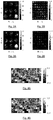
- the second order statistics (mean: figure 2A ; covariance: figure 2B ) of the control field for the Nova TX array are displayed for one axial slice through the brain.
- the mean control field ⁇ thus gives rise to eight axial images, each one corresponding to one TX channel.
- P ⁇ A and R ⁇ L identify the antero-posterior and the right-left directions of the subjects.
- Figures 3A and 3B display, for the same axial slice, the reduced statistics ⁇ and C ⁇ for the standardized fields statistics (mean: figure 3A ; covariance: figure 3B ).
- a visual comparison of figures 2A/2B and figures 3A/3B clearly indicates that the standardization procedure efficiently reduces the covariance of the control field vector.
- the adjustment matrices for the subjects may be computed using a reduced set of data.
- FIG 4C The difference in magnitude between the two adjustment matrices,
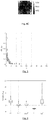
- Figure 5 is a plot of the d(L m , L 40 ) values for 1 ⁇ m ⁇ 40. It can be seen that for m ⁇ 3, d(L m , L 40 ) ⁇ 0.2. For m ⁇ 3 however, the estimation starts to diverge. This confirms that that a three-slice TX field mapping protocol would be sufficient to estimate correctly the projection matrix. Taking only the central slice for instance, however, would be insufficient (d(L m , L 40 ) > 0.5 for some subjects).
- the optimization was made on the flip angle (measuring by how much a magnetization initially along z is tipped from the z axis) distribution FA P, ⁇ 1 (r).
- the solution of the problem can be adapted to satisfy all hardware (peak RF power, average RF power or MFG slew rate limitations) or safety (specific absorption rate) constraints.
- the number of k T -points was set to 5, and their position in the k-space determined by the SRD approach described above.
- ⁇ 1 n denotes the subject-specific control field distribution for subject #n.
- P ST m U ST m ⁇ H ST m .
- P ST The subject-tailored solution obtained from m slices.
- the performance analysis of the UP, SUP consisted in simulating for every subject (36 simulations) the flip angle distribution and computing the Normalized Root Mean Square (NRMS) deviation of the latter from the target, referred below to as the flip angle NRMS control error (FA-NRMSE).
- NRMS Normalized Root Mean Square
- FA-NRMSE flip angle NRMS control error
- 5 pulses were tested the four pulses: i) P UP , ii) P SUP /L 40 , iii) P SUP /L 3 , iv) P ST , and v) P ST 3 where L 40 and L 3 are the subject-specific projection matrix calculated on all (40) slices and 3 slices respectively.
- SUP pulses provides better uniformity than the Universal Pulse (UP) approach, while requiring a rather simple calibration (e.g. only using three-slice MRI) for determining the subject-specific adjustment transformations.
- Subject-tailored (ST) pulses achieve even better uniformity, but they require a much heavier calibration (trying to reduce the complexity of the calibration step, as it was done in the ST 3 example, yields inacceptable results).
- the calibration step may be further simplified by deriving the inverse adjustment transformation for the user from measurements other than MR acquisitions. For instance, the measured noise covariance matrix for a plurality of receive channels of the MRI scanner is influenced by the subject body part in the scanner. A machine-learning algorithm may then be used to estimate the inverse adjustment matrix from noise measurements. Several different kind of measurements (e.g. MR and noise) may also be combined.
- Biometric and/or anagraphical data of the user may also be taken into account, combined with measurements, for estimating the adjustment transformations.
- Figure 7 is a very simplified representation of a parallel-transmission MRI apparatus (or scanner), suitable for carrying out the invention.
- Reference M designates a magnet for generating a strong (e.g. 3T or even 7T) static magnetic field B 0 oriented along a "longitudinal" direction z which, in the case of figure 7 , is horizontal.
- the magnet is cylindrical and hollow, to allow the insertion of a subject (typically a human being) or of a body part thereof (e.g. the head).
- Additional magnets called gradient coils (reference GC), are disposed outside the main magnet M and can be driven by slow (i.e.
- radio-frequency waveforms generating slowly-varying magnetic fields exhibiting intensity gradients along three orthogonal spatial dimensions (gradient waveforms).
- gradient waveforms intensity gradients along three orthogonal spatial dimensions
- a plurality of radio-frequency coil elements are arranged at the periphery of the internal volume of the main coil M; in the example of figure 7 there are 8 of them: RFC1, RFC2, RFC3, RFC4, RFC5, RFC6, RFC7, RFC8.
- the coil elements are part of respective transmission channels, also including non-represented devices such as amplifiers, which are independently driven by a computer to emit respective RF pulses which, in general, have a same carrier frequency (at the Larmor frequency) and different, time-varying amplitudes and phases, which may be defined by a complex envelope (RF waveforms).
- Receive channels are also provided for detecting a magnetic resonance signal (not represented).
- the computer also drives the gradient coils GC to generate gradient waveforms.
- the (inhomogeneous) RF field B1+ is generated by the RF coil elements; the ensemble formed by the RF coil elements is sometimes called a (RF) coil or array.
- the complex envelopes of a "standardized" pulse sequences comprising one RF waveform for each transmission channel of the scanner and gradient waveforms is stored in a memory device to which computer CP has access.
- computer CP is programmed to drive the scanner to perform measurements representative of spatial distributions of radio-frequency fields generated by the RF array; use the results of said measurements for estimating a subject-specific adjustment matrix, apply said adjustment matrix (or, rather, its inverse) to the standardized pulse to compute a subject-specific modified pulse and drive the RF and gradient coils to play the waveforms of the modified pulse.
Landscapes
- Physics & Mathematics (AREA)
- General Physics & Mathematics (AREA)
- Condensed Matter Physics & Semiconductors (AREA)
- High Energy & Nuclear Physics (AREA)
- Engineering & Computer Science (AREA)
- Signal Processing (AREA)
- Nuclear Medicine, Radiotherapy & Molecular Imaging (AREA)
- Radiology & Medical Imaging (AREA)
- General Health & Medical Sciences (AREA)
- Health & Medical Sciences (AREA)
- Optics & Photonics (AREA)
- Spectroscopy & Molecular Physics (AREA)
- Magnetic Resonance Imaging Apparatus (AREA)
Abstract
Description
- The invention relates to a method of designing a pulse sequence for parallel-transmission magnetic resonance imaging and of performing parallel-transmission magnetic resonance imaging using such a sequence. A pulse sequence comprises one or more radio-frequency (RF) waveforms, or pulses, and at least one magnetic field gradient waveform, allowing manipulating the nuclear magnetization of a sample immersed in a static magnetic field, resulting from the orientation of nuclear spins.
- High field magnetic resonance imaging (MRI) has proved its utility in clinical routine thanks to the high signal-to-noise ratio (SNR) it provides, allowing finer temporal and/or spatial resolutions. However, a number of problems inherent to high field still hamper the spread of high-field (3T - 7T) scanners in hospitals worldwide. Among them is the "B1 artifact" that occurs when the RF wavelength gets close to, or smaller than, the imaged region ([1]). In such a case, the transmitted radio-frequency "B1 +" field becomes inhomogeneous within the region of interest, resulting in an inhomogeneous distribution of nuclear magnetization flip angles. This leads to the appearance of zones of shade and loss of contrast, which can affect diagnosis by hiding pathologies or by altering the observed enhancement ratio in contrast-agent-injected sequences. At 3T, this artifact is particularly pregnant in abdominal imaging, and it becomes very problematic for brain imaging at ultra-high fields (UHF - 7T and above).
- Passive RF shimming involves the use of dielectric pads for compensating B1 inhomogeneity ([2]). Its effectiveness is somehow limited.
- Active RF shimming makes use of parallel transmission (pTx), i.e. of multiple RF coils for exciting nuclear spins. Two main sorts of active RF shimming techniques exist: static and dynamic.
- In static active RF shimming, the plurality of radio-frequency RF coil elements all transmit the same RF pulse with different complex weights, optimized to homogenize the B1 field [3]. For abdomen imaging at 3T, this technique is satisfactory for most patients, but it fails to offer homogeneous-enough excitation in about 10 to 20% of the cases, which is not acceptable. For higher field values, static active RF shimming is usually not satisfactory.
- Dynamic RF shimming [4] consists in using multiple RF coils to simultaneously transmit respective RF pulses having different temporal waveforms, usually defined by complex time-varying envelopes. This technique allows achieving better uniformity than static shimming, but its complexity has made it essentially a research tool.
- Reference [5] demonstrates the superiority of kT-points [6] dynamic RF shimming in clinical routine for nonselective excitation of the abdomen at 3T.
- Optimizing weighting coefficients (static shimming) or RF waveforms (dynamic shimming) requires calibration consisting at least in the measurement of B1 + maps from each transmit channel; moreover, for optimal dynamic RF shimming, an off-resonance frequency Δf0 map (corresponding to a static field inhomogeneity ΔB0 map if no chemical shift like fat tissue is present) is also required before computation of the RF pulse. These computations are time consuming. For instance, on a 3T scanner with two channels, the whole calibration process can last nearly two minutes: 30 seconds for B1 + mapping, 15 seconds for Δf0 mapping, and between 5 seconds (static RF shimming) and 60 seconds (kT-points) for pulse design itself. This is even worse when the number of channels increases.
- "Universal pulses", introduced in [7], allows calibration-free dynamic RF-shimming: instead of designing a pulse specific to each subject, a pulse robust to inter-subject variability is created once and for all using calibration data of a population of subjects. Universal pulses were successfully implemented in the brain at 7T, with a variety of sequences and weightings, and different underlying pulse designs.
- Universality, however, compromises individual homogeneity. Even if they provide acceptable results for a majority of the subjects, universal pulses fail to provide homogeneous-enough excitation in a significant number of cases.
- A compromise solution, suggested in [8], consists in computing different "semi-universal" pulses, tailored to different groups of imaging subjects. More precisely, according to [8], a set of subjects are grouped into a plurality of cohorts according to morphological features - e.g. the size of the head for brain imaging - and a "semi-universal" pulse sequence is designed for each cohort. The same morphological features are then used for choosing the best suited pulse sequence for additional subjects. A drawback of this approach is that the cohorts are formed on an empirical basis, with no guarantee of the relevance of the features used for sorting the imaging subjects.
- In order to overcome this drawback, [9] discloses a method - called "Smart Pulse" - wherein a population of subjects is divided into clusters, and one pseudo-universal pulse sequence is designed for each cluster. Then a machine learning algorithm classifies new subjects to assign the best possible pulse to each one of them on the basis of at least a morphological feature. Contrarily to the "semi-universal" approach of [8], the clusters are not defined empirically on the basis of somehow arbitrary morphological features, but in a systematic way using a clustering algorithm.
- The invention aims at providing a pulse design method providing better performances than the "Smart Pulse" approach in terms of fidelity to a target excitation pattern without requiring session-specific pulse engineering as e.g. in [4] - [6], but only a much simpler calibration process.
- The invention is based on a different approach to describe the session (i.e. MRI subject) dependence of the
actual 


- It is key to mention here that the computation of the adjustment transformation (matrix) essentially uses the subject-
specific 

full 
- Knowing the session specific adjustment matrix which, as mentioned above, is easily accessible with a rapid calibration technique, one may subsequently compute the so-called standardized resonant TX field distribution, defined as

- The inventors have experimentally verified that the covariance matrix of the standardized TX field distributions measured across several different individuals is substantially reduced as compared to the covariance matrix of the actual physical TX field. In other words, the adjustment transformation allows mapping the TX field distribution in a virtual space wherein the inter-subject variability in the resonant TX field in reduced.
- An idea at the basis of the invention is then to design a "universal" pulse sequence using standardized fields for a plurality of subjects instead of the actual physical TX fields. When pTX MRI has to be performed on a subject, a simple calibration method is used for estimating the subject's adjustment transformations; the pulse sequence suitable for this subject is then computed by applying the subject's inverse adjustment transformation to the "universal" sequence. Otherwise stated, the (inverse) adjustment transformation allows "customizing" the universal sequence derived from standardized fields.
- An object of the present invention is then a computer-implemented method of designing a pulse sequence for parallel-transmission magnetic resonance imaging, said pulse sequence comprising at least a magnetic field gradient waveform and a set of radio-frequency waveforms, each radio-frequency waveform of said set being associated to a respective transmit channel of a parallel-transmission magnetic resonance imaging apparatus, the method comprising:
- a) for each one of a plurality of magnetic resonance imaging subjects, estimating a linear transformation, called adjustment transformation, converting amplitude maps of radio-frequency fields generated within a region of interest comprising a body part of the subject by respective transmit channels of the magnetic resonance imaging apparatus into respective standardized maps, the adjustment transformation being chosen in such a way as to minimize a first cost function representative of an averaged difference between the standardized maps for the subject and respective reference amplitude maps for a reference subject; and
- b) determining at least said radio-frequency waveforms in such a way as to minimize a second cost function representative of a discrepancy between subject-specific distributions of flip-angles of nuclear spin and a target distribution, averaged over said plurality of magnetic resonance imaging subjects, the subject-specific distributions corresponding to the flip-angle distributions achieved by applying a magnetic field gradient waveform and a superposition of radio-frequency fields, each of said radio-frequency fields having a temporal profile described by one of said radio-frequency waveforms and a spatial amplitude distribution described by a respective standardized map determined for the subject.
- Another object of the invention is a method of performing parallel-transmission magnetic resonance imaging of a subject using a parallel-transmission magnetic resonance imaging apparatus comprising a set of gradient coils, a plurality of transmit channels and a plurality of receive channels, the method comprising the steps of:
- i) using the receive channels of the apparatus for performing measurements representative of spatial distributions of radio-frequency fields generated by respective transmit channels within a region of interest comprising a body part of the subject;
- ii) using results of said measurements, estimating a linear transformation, called adjustment transformation, converting amplitude maps of radio-frequency fields generated within the region of interest by respective transmit channels of the magnetic resonance imaging apparatus into respective standardized maps, the adjustment transformation being chosen in such a way as to minimize a cost function representative of an averaged difference between the standardized maps for the subject and respective reference amplitude maps for a reference subject;
- iii) inverting the adjustment transformation, and computing a set of subject-specific radio-frequency waveforms by applying the inverted adjustment transformation to a set of predetermined reference radio-frequency waveforms; and
- iv) applying each subject-specific radio-frequency waveform to a respective transmit channel while applying a magnetic field gradient waveform to the gradient coils, and using the receive channels to receive parallel-transmission magnetic resonance imaging signals.
- Yet another object of the invention is a parallel-transmission magnetic resonance imaging apparatus comprising a set of gradient coils, a plurality of transmit channels, a plurality of receive channels and a data processor, characterized in that:
- it further comprises a memory device storing data defining a set of predetermined reference radio-frequency waveforms and a magnetic field gradient waveform; and in that
- the data processor is programmed or configured for:
- driving the receive channels to perform measurements representative of spatial distributions of radio-frequency fields generated by the respective transmit channels within a region of interest comprising a body part of the subject;
- using results of said measurements, estimating a linear transformation, called adjustment transformation, converting amplitude maps of radio-frequency fields generated within the region of interest by respective transmit channels into respective standardized maps, the adjustment transformation being chosen in such a way as to minimize a cost function representative of an averaged difference between the standardized maps for the subject and respective reference amplitude maps for a reference subject;
- inverting the adjustment transformation and computing a set of subject-specific radio-frequency waveforms by applying the inverted adjustment transformation to a set of predetermined reference radio-frequency waveforms; and
- driving the transmit channels to play respective subject-specific radio-frequency waveforms, the gradient coils to play a magnetic field gradient waveform and the receive coil to receive parallel-transmission magnetic resonance imaging signals.
- Additional features and advantages of the present invention will become apparent from the subsequent description, taken in conjunction with the accompanying drawings, which show:
-
Figures 1A and 1B , respectively, flow-chart of a method for designing a "standardized" pulse sequence according to an embodiment of the invention and of a method for applying such a pulse sequence in a MRI session; -
Figures 2A and 2B , the second-order statistics of the radio-frequency fields generated by the transmission channels of a parallel-transmission MRI apparatus; -
Figures 3A and 3B , the second-order statistics of standardized fields corresponding to the radio-frequency fields offigures 2A and 2B ; -
Figures 4A, 4B , and4C , graphical representations of adjustment matrices for one particular subject; -
Figure 5 , a plot illustrating the impact of a reduction of the number of measurements used for estimating the adjustment matrices; -
Figure 6 , a plot illustrating the performances of different embodiments of the inventive methods, compared to those of the prior art; and -
Figure 7 , a schematic representation of a parallel-transmission magnetic resonance apparatus suitable for carrying out the invention. - A parallel-transmission magnetic resonance imaging apparatus comprising an array of Nc>1 RF coils (or resonators) implementing independently-driven transmit channels. The array is often cylindrical and encloses a region wherein a body part (e.g. the head) of a MRI subject can be introduced.
-
Figure 1A shows the different steps of a method for designing a pulse sequence according to an embodiment of the invention. - Let

field components 

- It is important to recall that the RF field spatial distribution is not only a function of the geometry of the array, but it is also affected by the presence of the body part and therefore depends on the MRI subject. The control field vector for a given realization - and therefore subject - can be measured using several known techniques, see e.g. [10].
- For a given realization of the control field ω1, corresponding to a particular MRI subject -designates the set of positions r where ω1(r) is known. As the control field distribution is typically obtained by MR (magnetic resonance) acquisitions, it is common in practice that
 is limited in space (no MR signal in air, and existence of regions where the reconstruction of

- The control field distribution

 . More precisely,

- Measured control fields for N > 1 (typically at least ten, and typically several tens) subjects, plus the reference subject, constitute the input data of a pulse design method according to one embodiment of the invention, as illustrated on
figure 1A . - In some embodiments of the invention, some or all of the control fields may be computed by performing full electromagnetic simulations taking into account the anatomy of real or virtual subjects.
- Let R ref denote the region over which the reference control field is defined. Let us denote by L(n) the Nc × Nc complex matrix (adjustment transformation, or matrix) satisfying:


- The adjustment transformations allow defining the Ω1,ref-standardized control field (or simply "standardized fields") as:

- It will be assumed that both the control fields and the standardized control fields are random variables following Gaussian laws defined by their second-order statistics: ω 1(r)∼N(µ(r), C(r)) and ω̃1(r)∼N(µ̃(r), C̃(r)) - the (n) apex are omitted when this is possible without inducing ambiguity. If the number N of subjects (excluding the reference subject) is much larger than Nc (by at least a factor of ten), the second-order statistics of the control fields can be computed as follows (where " * " represents Hermitian conjugation):


- Analogous formulas allow computing the second order statistics of the standardized control fields ("standardized control statistics").
- If N is not large enough, the Ledoit-Wolf estimation may be used for the covariance matrix.
- The set of standardized control fields - or simply the corresponding standardized control statistics - are then used to perform statistically robust design (SRD) of pulse sequences (the simpler term "pulse" will also be used) in accordance to a target control function f also provided as an input to the design method.
- Before describing a specific SRD approach, it is useful to recall some fundamental theoretical results.
- A spin excitation pulse sequence (or simply "pulse") is comprised of a set of time-discretized radiofrequency (RF) waveforms


- For simplicity, the pulse P, which is given by the definition of the RF and MFG waveforms U and H is denoted by:

- Neglecting relaxation and off-resonances during the excitation (this supposes that T ≪ T1,2 and off-resonance ≪


 and
and denote the real and imaginary part of z, respectively):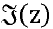

- The mapping (r, t) ↦ AP,ω
1 (r, t) - which depends on ω1 and P = U⊙H - completely characterizes the equation that governs the dynamics of the spin system. - Given a pulse P and a control field distribution , ω1, one may solve (at least numerically) Bloch's equation and express the magnetization at time T as:

- Where
A (r) is of the form:
- The pulse design engineering problem, conversely, consists in setting a condition on the desired control target of the form:

- In MRI, as the condition, generally, cannot be met perfectly for all positions simultaneously, this problem is usually solved by minimizing a metric of the form:
 denote a region of interest (e.g. corresponding to the brain), any point outside this region being ignored in this performance metric.
- When the control field ω1(r) is stochastic, then
A P,ω1 (r) is also stochastic and the pulse optimization can be recast into a so-called "statistic robust design" (SRD) problem. In this approach, anew design parameter 0 ≤ θ ≤ 1, called tolerance and the error level Δ are defined as :
A P (r)T)| exceeds Δ. - The optimization problem (14) becomes then:

- In practice the computation of Δ(P,θ) is difficult, therefore problem (14) is simplified into a more tractable optimization problem whose optimum is assumed to be close to the optimum of the above problem, see e.g. (14), (15).
- One such pulse engineering problem is given by the equation:

- As we have assumed that the statistical distribution of the control field ω1(r) is Gaussian with mean value µ(r) and covariance C(r), for all positions r, the term 〈FAP(r) - FAt〉)2 in Eq. 17 is a function of µ(r) and C(r). Thus, an interesting feature of equation (17) is that the optimization does not need full knowledge of the control fields, but only its second-order statistics, as illustrated on
figure 1A . A solution of such "relaxed" form of the pulse engineering problem f(r, eA (r)T) = 0 taking into account the statistical distribution of the control field ω1 is said to be designed on ω1's statistics. - Typically, the desired control target function f represents a target distribution of flip angles of nuclear spins, FAt. Most often, but not always, this target distribution corresponds to a constant flip angle over a region of interest (e.g. a subject's brain).
- The flip angle distribution FAP,ω
1 (r).is computed from equation (10) as follows
- In other words, the local performance metric f(r, e
A P,ω1 (r)T) (see Equation 12) here takes the form:
- For simplicity, here, neither constraints on the energy of the pulse nor on the MFG slew rate are taken into account here. However these constraints can be added explicitly to the pulse engineering problem by replacing the pulse engineering problem of Eq. (16) with the constrained optimization problem:

Where
- It should be understood that equation (16) is only one example of a "relaxed" optimization problem. Different forms of the problem, or even the true SRD optimization problem (16), can be applied to different embodiments of the invention, and in some cases deeper knowledge of the control fields will be required.
- Moreover, according to different embodiments of the invention, both the RF waveform U and the gradient waveform H can be optimized, or only the RF waveform, the gradient waveform being predefined.
- An essential feature of the invention, distinguishing it from the prior art, comes from the observation that statistically robust pulse design can be carried out using the standardized control fields ω̃1 (n)(r) (or their second-order statistics) rather than the "physical" fields ω1 (n)(r). In the example of the relaxed form of the SRD optimization problem (16), this is equivalent to replacing 〈f(r, e
A P,ω1 (r)T)〉2 with 〈f(r, eA P, ω̃ 1 (r)T)〉2. The result of such design is called a "standardized" pulse P = U⊙H. - Directly exposing a MRI subject to a standardized pulse would not provide the expected result, i.e. a spin flip angle distribution approximately matching the target. However let us consider, for a subject whose adjustment matrix is "L", a modified spin excitation pulse P' = U'⊙H such that:

- Otherwise stated, the RF component of P' is modified by being right-multiplied by the inverse adjustment matrix for the subject.
- It can be observed that:

- And therefore:

- In order to perform spin-excitation on a subject it is then necessary to compute an estimator L of its adjustment matrix, and then to apply the inverse of the estimated adjustment matrix to the standardized pulse (rather, to its RF component), to obtain a modified pulse, specific to the subject and fit for the purpose defined during the standardized pulse design phase. This is illustrated on
figure 1B , where
- As discussed above, given that the least-squares problem given by Eq.1 is largely overdetermined, the estimator L can be satisfactorily estimated from a subsampled control field

 . Therefore, the computation of L̂ is much more efficient than the computation of a subject-specific optimal pulse.
- The advantages provided by the invention will now be discussed with the help of a specific numerical example, illustrated by
figures 2A to 6 . - MRI data were obtained on a parallel transmit enabled whole body Siemens 7T system (Siemens Healthineers, Erlangen, Germany) equipped with an SC72 whole body gradient insert (200 mT/m/ms and 70 mT/m maximum gradient slew rate and maximum gradient amplitude). The parallel transmission system consisted of eight transmitters (1 kW peak power per channel). Measurements were made with the 8Tx-32Rx Nova head coil (Nova Medical, Wilmington, MA, USA). The data consist of a collection of N=36

- The protocol used to reconstruct the

matrix size 40 × 64 × 40, TR = 20 s, TA = 4 min 40 s). - In
Figures 2A and 2B , the second order statistics (mean:figure 2A ; covariance:figure 2B ) of the control field for the Nova TX array are displayed for one axial slice through the brain. The mean control field µ thus gives rise to eight axial images, each one corresponding to one TX channel. - P←A and R→L identify the antero-posterior and the right-left directions of the subjects.
-
Figures 3A and 3B display, for the same axial slice, the reduced statistics µ̃ and C̃ for the standardized fields statistics (mean:figure 3A ; covariance:figure 3B ). A visual comparison offigures 2A/2B and figures 3A/3B clearly indicates that the standardization procedure efficiently reduces the covariance of the control field vector. - As explained above, the adjustment matrices for the subjects may be computed using a reduced set of data. A particularly suitable choice for the subsampling operator F of equation (23) is the operator that selects a subset of the ensemble of acquired slices (Ns denoting the number of acquired slices). For 1 ≤ m ≤ Ns, Fn denotes the operation consisting in retaining m evenly distributed slices across the optimization region (in this example, the volume of the brain) and Lm = LF
m . - On
figures 4A and 4B , the 36 adjustment matrices (one per subject, the projection matrix for the first subject being the identity matrix) are shown for m = 40 (L40,figure 4A ) and m = 3 (L3,figure 4B ). Real and imaginary parts of the matrices are concatenated horizontally, and the 8x8 identity matrix I8 is subtracted from every matrix to ease the visualization. Visually, there is hardly any difference between L3 (only three slices used) and L40 (all slices used). We found that
subjects 2 to 36). This demonstrates that a substantially reduced dataset (3 slices out of 40) allows a satisfactory estimation of the adjustment matrices. - The difference in magnitude between the two adjustment matrices, |L3 - L40| is shown in
Fig 4C ;
Figure 5 is a plot of the d(Lm, L40) values for 1 ≤ m ≤ 40. It can be seen that for m ≥ 3, d(Lm, L40) < 0.2. For m < 3 however, the estimation starts to diverge. This confirms that that a three-slice TX field mapping protocol would be sufficient to estimate correctly the projection matrix. Taking only the central slice for instance, however, would be insufficient (d(Lm, L40) > 0.5 for some subjects). - Universal kT-point pulses ([6]) for the Nova TX array where designed by following the SRD approach described above, optimized to create uniform 10° flip angle excitation across the brain. For that purpose, the design region,, was defined as:


- For the design, the spins were assumed to be on-resonant (ω0 = 0) everywhere across the head. The optimization was made on the flip angle (measuring by how much a magnetization initially along z is tipped from the z axis) distribution FAP,ω̃
1 (r). - For simplicity, here, no constraint on the energy of the pulse nor on the MFG slew rate was taken into account. However, once the solution of the problem is determined, by possibly increasing the sub-pulse and MFG blip duration, the solution can be adapted to satisfy all hardware (peak RF power, average RF power or MFG slew rate limitations) or safety (specific absorption rate) constraints. In this numerical application, the number of kT-points was set to 5, and their position in the k-space determined by the SRD approach described above.
- Statistical robust solutions were computed numerically with the natural (µ, C) and the reduced (µ̃, C̃) control field statistics as input statistics using Equation (16) ("relaxed" SRD). The solution computed using the second-order statistics (µ, C) of the natural fields will be called in the following "Universal Pulse" UP, as it corresponds to the method disclosed in [7]. The solution computed using the second-order statistics (µ̃, C̃) of the standardized fields will be called in the following "Standardized Universal Pulses" SUP.
- For every subject, subject-tailored (ST) pulses were also computed, using the same parameterization as for the UP and SUP. The cost function to minimize was:

- Where we recall that

- The subject-tailored solution obtained from m slices is denoted by PST
m = UST m ⊙HST m . When the complete set of slices is used, it is simply referred to as PST. - The performance analysis of the UP, SUP consisted in simulating for every subject (36 simulations) the flip angle distribution and computing the Normalized Root Mean Square (NRMS) deviation of the latter from the target, referred below to as the flip angle NRMS control error (FA-NRMSE). Here, for every realization of the control field (i.e., every subject), 5 pulses were tested the four pulses: i) PUP, ii) PSUP/L40, iii) PSUP/L3, iv) PST, and v) PST
3 where L40 and L3 are the subject-specific projection matrix calculated on all (40) slices and 3 slices respectively. - The result of the FA-NRMSE analysis is presented in
Figure 6 where, for each kind of pulse, the error bar identifies the lowest and highest NRMSE, the horizontal bar in the middle its median value and the box contains 75% of the subjects. The plot displays a FA-NRMSE on average equal to 8% with the 5-kT-point UP against -5% with the equivalent 5-kT-point SUP, i.e. nearly the ultimate UP performance. An optimal adjustment of the SUP (PSUP ↦ PSUP/L40) or an adjustment of the SUP with only 3 slices (PSUP ↦ PSUP/L3) are seen to yield very comparable performances in terms of FA-NRMSE (on average across subject 5.5% and 5.7% respectively), confirming the analysis reported inFig. 5 . The subject tailored pulse returns a FA-NRMSE, on average equal to 2.3% when all slices were used for the pulse design (ST) and increased to 8.4% when only three slices where used (ST3). - In conclusion, the inventive method (SUP pulses) provides better uniformity than the Universal Pulse (UP) approach, while requiring a rather simple calibration (e.g. only using three-slice MRI) for determining the subject-specific adjustment transformations. Subject-tailored (ST) pulses achieve even better uniformity, but they require a much heavier calibration (trying to reduce the complexity of the calibration step, as it was done in the ST3 example, yields inacceptable results).
- The calibration step may be further simplified by deriving the inverse adjustment transformation for the user from measurements other than MR acquisitions. For instance, the measured noise covariance matrix for a plurality of receive channels of the MRI scanner is influenced by the subject body part in the scanner. A machine-learning algorithm may then be used to estimate the inverse adjustment matrix from noise measurements. Several different kind of measurements (e.g. MR and noise) may also be combined.
- Biometric and/or anagraphical data of the user (e.g. size of the head, sex, age...) may also be taken into account, combined with measurements, for estimating the adjustment transformations.
-
Figure 7 is a very simplified representation of a parallel-transmission MRI apparatus (or scanner), suitable for carrying out the invention. Reference M designates a magnet for generating a strong (e.g. 3T or even 7T) static magnetic field B0 oriented along a "longitudinal" direction z which, in the case offigure 7 , is horizontal. The magnet is cylindrical and hollow, to allow the insertion of a subject (typically a human being) or of a body part thereof (e.g. the head). Additional magnets, called gradient coils (reference GC), are disposed outside the main magnet M and can be driven by slow (i.e. not at radio-frequency) waveforms generating slowly-varying magnetic fields exhibiting intensity gradients along three orthogonal spatial dimensions (gradient waveforms). On the figure, only a pair of gradient coils is represented, allowing the generation of a gradient along a single spatial dimension. A plurality of radio-frequency coil elements are arranged at the periphery of the internal volume of the main coil M; in the example offigure 7 there are 8 of them: RFC1, RFC2, RFC3, RFC4, RFC5, RFC6, RFC7, RFC8. The coil elements are part of respective transmission channels, also including non-represented devices such as amplifiers, which are independently driven by a computer to emit respective RF pulses which, in general, have a same carrier frequency (at the Larmor frequency) and different, time-varying amplitudes and phases, which may be defined by a complex envelope (RF waveforms). Receive channels are also provided for detecting a magnetic resonance signal (not represented). - The computer also drives the gradient coils GC to generate gradient waveforms. The (inhomogeneous) RF field B1+ is generated by the RF coil elements; the ensemble formed by the RF coil elements is sometimes called a (RF) coil or array.
- According to the invention, the complex envelopes of a "standardized" pulse sequences, comprising one RF waveform for each transmission channel of the scanner and gradient waveforms is stored in a memory device to which computer CP has access. Moreover, computer CP is programmed to drive the scanner to perform measurements representative of spatial distributions of radio-frequency fields generated by the RF array; use the results of said measurements for estimating a subject-specific adjustment matrix, apply said adjustment matrix (or, rather, its inverse) to the standardized pulse to compute a subject-specific modified pulse and drive the RF and gradient coils to play the waveforms of the modified pulse.
-
- 1. Bernstein MA, Huston J, Ward HA. Imaging artifacts at 3.0T. J Magn Reson Imaging. 2006;24(4):735-746. doi:10.1002/jmri.20698
- 2. Franklin Kendra M., Dale Brian M., Merkle Elmar M. Improvement in B1-inhomogeneity artifacts in the abdomen at 3T MR imaging using a radiofrequency cushion. J Magn Reson Imaging. 2008;27(6):1443-1447. doi:10.1002/jmri.21164
- 3. J. V. Hajnal, S. J. Malik, D. J. Larkman, D. O'Regan, K. Nehrke, U. Katscher, I. Graesslin, and P. Börnert, Initial Experience with RF shimming at 3T using a whole body 8 channel RF system, in Proceedings of the 16th Annual Meeting of ISMRM, Toronto, Ontario, Canada, 2008. p. 496.
- 4. Katscher U, Börnert P, Leussler C, van den Brink JS. Transmit SENSE. Magn Reson Med. 2003;49(1):144-150. doi:10.1002/mrm.10353
- 5. Tomi-Tricot R, Gras V, Mauconduit F, et al. B1 artifact reduction in abdominal DCE-MRI using kT-points: First clinical assessment of dynamic RF shimming at 3T. J Magn Reson Imaging.:n/a-n/a. doi:10.1002/jmri.25908
- 6. Cloos MA, Boulant N, Luong M, et al. kT-points: Short three-dimensional tailored RF pulses for flip-angle homogenization over an extended volume. Magnetic Resonance in Medicine 67:72-80 (2012).
- 7. Gras V, Vignaud A, Amadon A, Bihan DL, Boulant N. Universal pulses: A new concept for calibration-free parallel transmission. Magn Reson Med. 2017;77(2):635-643. doi:10.1002/mrm.26148
- 8.
WO2017/060142 - 9. Raphael Tomi-Tricot, Vincent Gras, Bertrand Thirion, Franck Mauconduit, Nicolas Boulant, et al.. SmartPulse, a Machine Learning Approach for Calibration-Free Dynamic RF Shimming: Preliminary Study in a Clinical Environment. Magnetic Resonance in Medicine, Wiley, 2019, Magn Reson Med., 82, pp.2016-2031.
- 10. Brunheim et al., "Fast and accurate multi-channel mapping based on the TIAMO technique for 7T UHF body MRI," Magnetic Resonance in Medicine, vol. 79, no. 5, pp. 2652-2664, 2018.
- 11. P. Alotto, C. Magele, W. Renhart, A. Weber, and G. Steiner, "Robust target functions in electromagnetic design," COMPEL, vol. 22, no. 3, pp. 549-560, Sep. 2003.
- 12. G. Steiner, D. Watzenig, C. Magele, and U. Baumgartner, "Statistical robust design using the unscented transformation," COMPEL - The international journal for computation and mathematics in electrical and electronic engineering, vol. 24, no. 2, pp. 606-619, Jun. 2005.
- 13. H.-P. Fautz, M. H. Vogel, P. Gross, A. Kerr, and Y. Zhu, "B1 mapping of coil arrays for parallel transmission," In Proceedings of the 16th Annual Meeting of ISMRM, p. 1247, 2008.
- 14. D. O. Brunner and K. P. Pruessmann, "B1+ interferometry for the calibration of RF transmitter arrays," Magn Reson Med, vol. 61, no. 6, pp. 1480-1488, 2009.
- 15. A. Amadon, M. A. Cloos, N. Boulant, M.-F. Hang, C. J. Wiggins, and H.-P. Fautz, "Validation of a very fast B1-mapping sequence for parallel transmission on a human brain at 7T," In Proceedings of the 20th Annual Meeting of ISMRM, p. 3358, 2012.
Claims (12)
- A computer-implemented method of designing a pulse sequence (P) for parallel-transmission magnetic resonance imaging, said pulse sequence comprising at least a magnetic field gradient waveform (H) and a set of radio-frequency waveforms (U), each radio-frequency waveform of said set being associated to a respective transmit channel (RFC1 - RFC8) of a parallel-transmission magnetic resonance imaging apparatus, the method comprising:a) for each one of a plurality of magnetic resonance imaging subjects, estimating a linear transformation, called adjustment transformation (L), converting amplitude maps (Ω1 (1) - Ω1 (1)) of radio-frequency fields generated within a region of interest comprising a body part of the subject by respective transmit channels of the magnetic resonance imaging apparatus into respective standardized maps
 b) determining at least said radio-frequency waveforms (U) in such a way as to minimize a second cost function representative of a discrepancy between subject-specific distributions of flip-angles of nuclear spin and a target distribution, averaged over said plurality of magnetic resonance imaging subjects, the subject-specific distributions corresponding to the flip-angle distributions achieved by applying a magnetic field gradient waveform and a superposition of radio-frequency fields, each of said radio-frequency fields having a temporal profile described by one of said radio-frequency waveforms and a spatial amplitude distribution described by a respective standardized map determined for the subject.
 - The method of claim 1 wherein step b) further comprising determining said magnetic field gradient waveform (H) so as to minimize said second cost function.
- The method of any one of the preceding claims further comprising a preliminary step of acquiring all or some of said amplitude maps using the magnetic resonance imaging apparatus, the acquired amplitude maps being used for estimating the adjustment transformation.
- The method of any one of the preceding claims further comprising a preliminary step of computing all or some of said amplitude maps by performing an electromagnetic simulation using a computer, the simulated amplitude maps being used for estimating the adjustment transformation.
- The method of any one of the preceding claims further comprising a preliminary step of measuring a noise covariance matrix for a plurality of receive channels of the parallel-transmission magnetic resonance imaging apparatus, the measured noise covariance matrix being used for estimating the adjustment transformation.
- The method of any one of the preceding claims, wherein step a) further comprises computing second-order statistics of the standardized maps and step b) comprises determining at least said radio-frequency waveforms from said second-order statistics.
- The method of any one of the preceding claims wherein the target distribution is homogeneous over a region of interest.
- A method of performing parallel-transmission magnetic resonance imaging of a subject using a parallel-transmission magnetic resonance imaging apparatus comprising a set of gradient coils (GC), a plurality of transmit channels (RFC1 - RFC8) and a plurality of receive channels, the method comprising the steps of:i) using the receive channels of the apparatus for performing measurements representative of spatial distributions of radio-frequency fields generated by respective transmit channels within a region of interest comprising a body part of the subject;ii) using results of said measurements, estimating a linear transformation (L), called adjustment transformation, converting amplitude maps (Q1 (1) - Q1 (1)) of radio-frequency fields generated within the region of interest by respective transmit channels of the magnetic resonance imaging apparatus into respective standardized maps
 iii) inverting the adjustment transformation, and computing a set of subject-specific radio-frequency waveforms (P') by applying the inverted adjustment transformation to a set of predetermined reference radio-frequency waveforms; andiv) applying each subject-specific radio-frequency waveform to a respective transmit channel while applying a magnetic field gradient waveform to the gradient coils, and using the receive channels to receive parallel-transmission magnetic resonance imaging signals.
 - The method of claim 8, wherein said set of predetermined reference radio-frequency waveforms has been obtained using a method according to any one of claims 1 to 7.
- The method of any one of claims 8 or 9, wherein step i) comprises acquiring amplitude maps of said radio-frequency fields with a lower spatial resolution than that of the receive parallel-transmission magnetic resonance imaging signals acquired during step iv).
- The method of any one of claims 8 to 10, wherein step i) comprises measuring a noise covariance matrix for said receive channels.
- A parallel-transmission magnetic resonance imaging apparatus comprising a set of gradient coils (GC), a plurality of transmit channels (RFC1 - RFC8), a plurality of receive channels and a data processor (CP), characterized in that:- it further comprises a memory device (DB) storing data defining a set of predetermined reference radio-frequency waveforms and a magnetic field gradient waveform; and in that- the data processor is programmed or configured for:- driving the receive channels to perform measurements representative of spatial distributions of radio-frequency fields (Q1 (1) - Q1 (1)) generated by the respective transmit channels within a region of interest comprising a body part of the subject;- using results of said measurements, estimating a linear transformation (L), called adjustment transformation, converting amplitude maps of radio-frequency fields generated within the region of interest by respective transmit channels into respective standardized maps
 - inverting the adjustment transformation and computing a set of subject-specific radio-frequency waveforms by applying the inverted adjustment transformation to a set of predetermined reference radio-frequency waveforms; and- driving the transmit channels to play respective subject-specific radio-frequency waveforms, the gradient coils to play a magnetic field gradient waveform and the receive coil to receive parallel-transmission magnetic resonance imaging signals.
Priority Applications (4)
| Application Number | Priority Date | Filing Date | Title |
|---|---|---|---|
| EP19306589.3A EP3832336B1 (en) | 2019-12-06 | 2019-12-06 | A method of designing a pulse sequence for parallel-transmission mri, and a method of performing parallel-transmission mri using such a pulse sequence |
| JP2020183475A JP7612381B2 (en) | 2019-12-06 | 2020-11-02 | Method for designing a parallel transmission MRI pulse sequence and method for performing parallel transmission MRI using such a pulse sequence - Patents.com |
| KR1020200166811A KR102895196B1 (en) | 2019-12-06 | 2020-12-02 | A method of designing a pulse sequence for parallel-transmission mri, and a method of performing parallel-transmission mri using such a pulse sequence |
| US17/110,598 US11262427B2 (en) | 2019-12-06 | 2020-12-03 | Method of designing a pulse sequence for parallel-transmission MRI, and a method of performing parallel-transmission MRI using such a pulse sequence |
Applications Claiming Priority (1)
| Application Number | Priority Date | Filing Date | Title |
|---|---|---|---|
| EP19306589.3A EP3832336B1 (en) | 2019-12-06 | 2019-12-06 | A method of designing a pulse sequence for parallel-transmission mri, and a method of performing parallel-transmission mri using such a pulse sequence |
Publications (2)
| Publication Number | Publication Date |
|---|---|
| EP3832336A1 true EP3832336A1 (en) | 2021-06-09 |
| EP3832336B1 EP3832336B1 (en) | 2021-11-17 |
Family
ID=69005655
Family Applications (1)
| Application Number | Title | Priority Date | Filing Date |
|---|---|---|---|
| EP19306589.3A Active EP3832336B1 (en) | 2019-12-06 | 2019-12-06 | A method of designing a pulse sequence for parallel-transmission mri, and a method of performing parallel-transmission mri using such a pulse sequence |
Country Status (4)
| Country | Link |
|---|---|
| US (1) | US11262427B2 (en) |
| EP (1) | EP3832336B1 (en) |
| JP (1) | JP7612381B2 (en) |
| KR (1) | KR102895196B1 (en) |
Families Citing this family (2)
| Publication number | Priority date | Publication date | Assignee | Title |
|---|---|---|---|---|
| US20230346247A1 (en) * | 2022-05-02 | 2023-11-02 | The General Hospital Corporation | System and method for magnetic resonance imaging using shaped radio frequency pulses |
| DE102024206085B4 (en) * | 2024-06-28 | 2026-04-02 | Siemens Healthineers Ag | Improved acquisition of magnetic resonance data to avoid cropping effects |
Citations (1)
| Publication number | Priority date | Publication date | Assignee | Title |
|---|---|---|---|---|
| WO2017060142A1 (en) | 2015-10-06 | 2017-04-13 | Commissariat A L'energie Atomique Et Aux Energies Alternatives | A method of designing pulse sequences for parallel-transmission magnetic resonance imaging, and a method of performing magnetic resonance imaging using such sequences |
Family Cites Families (4)
| Publication number | Priority date | Publication date | Assignee | Title |
|---|---|---|---|---|
| GB2476433B (en) * | 2008-09-17 | 2013-01-09 | Koninkl Philips Electronics Nv | B1 Mapping and B1L-Shimming for MRI |
| EP2572210A1 (en) * | 2010-05-21 | 2013-03-27 | Commissariat à l'Énergie Atomique et aux Énergies Alternatives | Method and apparatus for correcting bl - inhomogeneity in slice - selective mri using composite rf pulses |
| EP2933650A1 (en) * | 2014-04-17 | 2015-10-21 | Commissariat A L'energie Atomique Et Aux Energies Alternatives | Use of an optimal control algorithm for the design of MRI refocusing pulses with phase-free rotation axis |
| EP3594710B1 (en) * | 2018-07-09 | 2024-04-17 | Commissariat à l'Energie Atomique et aux Energies Alternatives | A computer-implemented method of building a database of pulse sequences for magnetic resonance imaging, and a method of performing magnetic resonance imaging using such a database |
-
2019
- 2019-12-06 EP EP19306589.3A patent/EP3832336B1/en active Active
-
2020
- 2020-11-02 JP JP2020183475A patent/JP7612381B2/en active Active
- 2020-12-02 KR KR1020200166811A patent/KR102895196B1/en active Active
- 2020-12-03 US US17/110,598 patent/US11262427B2/en active Active
Patent Citations (1)
| Publication number | Priority date | Publication date | Assignee | Title |
|---|---|---|---|---|
| WO2017060142A1 (en) | 2015-10-06 | 2017-04-13 | Commissariat A L'energie Atomique Et Aux Energies Alternatives | A method of designing pulse sequences for parallel-transmission magnetic resonance imaging, and a method of performing magnetic resonance imaging using such sequences |
Non-Patent Citations (16)
| Title |
|---|
| A. AMADONM. A. CLOOSN. BOULANTM.-F. HANGC. J. WIGGINSH.-P. FAUTZ: "Validation of a very fast B1-mapping sequence for parallel transmission on a human brain at 7T", PROCEEDINGS OF THE 20TH ANNUAL MEETING OF ISMRM, 2012, pages 3358 |
| BERNSTEIN MAHUSTON JWARD HA: "Imaging artifacts at 3.0T", J MAGN RESON IMAGING, vol. 24, no. 4, 2006, pages 735 - 746, XP002603526 |
| BRUNHEIM ET AL.: "Fast and accurate multi-channel mapping based on the TIAMO technique for 7T UHF body MRI", MAGNETIC RESONANCE IN MEDICINE, vol. 79, no. 5, 2018, pages 2652 - 2664 |
| CLOOS MABOULANT NLUONG M ET AL.: "kT-points: Short three-dimensional tailored RF pulses for flip-angle homogenization over an extended volume", MAGNETIC RESONANCE IN MEDICINE, vol. 67, 2012, pages 72 - 80, XP055046630, DOI: 10.1002/mrm.22978 |
| D. O. BRUNNERK. P. PRUESSMANN: "B1+ interferometry for the calibration of RF transmitter arrays", MAGN RESON MED, vol. 61, no. 6, 2009, pages 1480 - 1488 |
| FRANKLIN KENDRA M.DALE BRIAN M.MERKLE ELMAR M.: "Improvement in B1-inhomogeneity artifacts in the abdomen at 3T MR imaging using a radiofrequency cushion", J MAGN RESON IMAGING, vol. 27, no. 6, 2008, pages 1443 - 1447 |
| G. STEINERD. WATZENIGC. MAGELEU. BAUMGARTNER: "Statistical robust design using the unscented transformation", COMPEL - THE INTERNATIONAL JOURNAL FOR COMPUTATION AND MATHEMATICS IN ELECTRICAL AND ELECTRONIC ENGINEERING, vol. 24, no. 2, June 2005 (2005-06-01), pages 606 - 619 |
| GRAS VVIGNAUD AAMADON ABIHAN DLBOULANT N: "Universal pulses: A new concept for calibration-free parallel transmission", MAGN RESON MED., vol. 77, no. 2, 2017, pages 635 - 643, XP055340677, DOI: 10.1002/mrm.26148 |
| H.-P. FAUTZM. H. VOGELP. GROSSA. KERRY. ZHU: "B1 mapping of coil arrays for parallel transmission", PROCEEDINGS OF THE 16TH ANNUAL MEETING OF ISMRM, 2008, pages 1247, XP055085759 |
| J. V. HAJNALS. J. MALIKD. J. LARKMAND. O'REGANK. NEHRKEU. KATSCHERI. GRAESSLINP. BORNERT: "Initial Experience with RF shimming at 3T using a whole body 8 channel RF system", PROCEEDINGS OF THE 16TH ANNUAL MEETING OF ISMRM, 2008, pages 496 |
| KATSCHER UBORNERT PLEUSSLER CVAN DEN BRINK JS: "Transmit SENSE", MAGN RESON MED., vol. 49, no. 1, 2003, pages 144 - 150, XP009016770, DOI: 10.1002/mrm.10353 |
| P. ALOTTOC. MAGELEW. RENHARTA. WEBERG. STEINER: "Robust target functions in electromagnetic design", COMPEL, vol. 22, no. 3, September 2003 (2003-09-01), pages 549 - 560 |
| RAPHAËL TOMI-TRICOT ET AL: "SmartPulse, a machine learning approach for calibration-free dynamic RF shimming: Preliminary study in a clinical environment", MAGNETIC RESONANCE IN MEDICINE., vol. 82, no. 6, 30 June 2019 (2019-06-30), US, pages 2016 - 2031, XP055699831, ISSN: 0740-3194, DOI: 10.1002/mrm.27870 * |
| RAPHAEL TOMI-TRICOTVINCENT GRASBERTRAND THIRIONFRANCK MAUCONDUITNICOLAS BOULANT ET AL.: "Magnetic Resonance in Medicine", vol. 82, 2019, WILEY, article "SmartPulse, a Machine Learning Approach for Calibration-Free Dynamic RF Shimming: Preliminary Study in a Clinical Environment", pages: 2016 - 2031 |
| TOMI-TRICOT RGRAS VMAUCONDUIT F ET AL.: "B1 artifact reduction in abdominal DCE-MRI using kT-points: First clinical assessment of dynamic RF shimming at 3T", J MAGN RESON IMAGING.:N/A-N/A |
| VINCENT GRAS ET AL: "Universal pulses: A new concept for calibration-free parallel transmission", MAGNETIC RESONANCE IN MEDICINE., vol. 77, no. 2, 17 February 2016 (2016-02-17), US, pages 635 - 643, XP055340677, ISSN: 0740-3194, DOI: 10.1002/mrm.26148 * |
Also Published As
| Publication number | Publication date |
|---|---|
| JP7612381B2 (en) | 2025-01-14 |
| EP3832336B1 (en) | 2021-11-17 |
| US11262427B2 (en) | 2022-03-01 |
| US20210173031A1 (en) | 2021-06-10 |
| JP2021090725A (en) | 2021-06-17 |
| KR20210071843A (en) | 2021-06-16 |
| KR102895196B1 (en) | 2025-12-03 |
Similar Documents
| Publication | Publication Date | Title |
|---|---|---|
| US7633293B2 (en) | Radio frequency field localization for magnetic resonance | |
| US10459056B2 (en) | Method of designing pulse sequences for parallel-transmission magnetic resonance imaging, and a method of performing magnetic resonance imaging using such sequences | |
| EP3594710B1 (en) | A computer-implemented method of building a database of pulse sequences for magnetic resonance imaging, and a method of performing magnetic resonance imaging using such a database | |
| EP3673282B1 (en) | Data-driven correction of phase depending artefacts in a magnetic resonance imaging system | |
| EP3803428B1 (en) | Motion detection in cest magnetic resonance imaging based on z-spectrum analysis | |
| US11262427B2 (en) | Method of designing a pulse sequence for parallel-transmission MRI, and a method of performing parallel-transmission MRI using such a pulse sequence | |
| EP2399142B1 (en) | Use of strongly modulating pulses in mri for providing chemical shift selective flip angles | |
| US11754651B2 (en) | Patient-model-based determination of a stimulation of a magnetic resonance imaging | |
| EP4455710B1 (en) | Shimming method and shimming apparatus | |
| Bhogal et al. | Image‐based method to measure and characterize shim‐induced eddy current fields | |
| US12181549B2 (en) | Method for determining a B0 map | |
| US10557909B2 (en) | Method and magnetic resonance tomography apparatus for diffusion imaging | |
| US20250251475A1 (en) | Magnetic resonance imaging with machine-learning based shim settings | |
| JP7780926B2 (en) | Medical data processing device, medical data processing method, medical data processing program, and magnetic resonance imaging device | |
| Sánchez Alarcón et al. | Reproducibility of tailored and universal nonselective excitation pulses at 7 T for human cardiac MRI: A 3‐year and an interday study | |
| Jamil | Development of a high spatial resolution functional MRI sequence at ultra-high field | |
| Filos et al. | Parallel transmission MRI | |
| JP2025037822A (en) | B1 map determination method and B1 map determination device | |
| Tong | Applications of parallel radiofrequency transmission to ultra-high-field magnetic resonance imaging | |
| GB2621372A (en) | Method of analysing medical images | |
| US10024942B2 (en) | Magnetic resonance method and apparatus to generate a residual map as an indicator of signal model consistency | |
| Yetişir | Parallel radiofrequency transmission for 3 Tesla and 7 Tesla magnetic resonance imaging |
Legal Events
| Date | Code | Title | Description |
|---|---|---|---|
| STAA | Information on the status of an ep patent application or granted ep patent |
Free format text: STATUS: EXAMINATION IS IN PROGRESS |
|
| PUAI | Public reference made under article 153(3) epc to a published international application that has entered the european phase |
Free format text: ORIGINAL CODE: 0009012 |
|
| 17P | Request for examination filed |
Effective date: 20191206 |
|
| AK | Designated contracting states |
Kind code of ref document: A1 Designated state(s): AL AT BE BG CH CY CZ DE DK EE ES FI FR GB GR HR HU IE IS IT LI LT LU LV MC MK MT NL NO PL PT RO RS SE SI SK SM TR |
|
| GRAP | Despatch of communication of intention to grant a patent |
Free format text: ORIGINAL CODE: EPIDOSNIGR1 |
|
| STAA | Information on the status of an ep patent application or granted ep patent |
Free format text: STATUS: GRANT OF PATENT IS INTENDED |
|
| INTG | Intention to grant announced |
Effective date: 20210715 |
|
| GRAS | Grant fee paid |
Free format text: ORIGINAL CODE: EPIDOSNIGR3 |
|
| GRAA | (expected) grant |
Free format text: ORIGINAL CODE: 0009210 |
|
| STAA | Information on the status of an ep patent application or granted ep patent |
Free format text: STATUS: THE PATENT HAS BEEN GRANTED |
|
| AK | Designated contracting states |
Kind code of ref document: B1 Designated state(s): AL AT BE BG CH CY CZ DE DK EE ES FI FR GB GR HR HU IE IS IT LI LT LU LV MC MK MT NL NO PL PT RO RS SE SI SK SM TR |
|
| REG | Reference to a national code |
Ref country code: GB Ref legal event code: FG4D |
|
| REG | Reference to a national code |
Ref country code: IE Ref legal event code: FG4D |
|
| REG | Reference to a national code |
Ref country code: DE Ref legal event code: R096 Ref document number: 602019009365 Country of ref document: DE |
|
| REG | Reference to a national code |
Ref country code: AT Ref legal event code: REF Ref document number: 1448482 Country of ref document: AT Kind code of ref document: T Effective date: 20211215 |
|
| REG | Reference to a national code |
Ref country code: LT Ref legal event code: MG9D |
|
| REG | Reference to a national code |
Ref country code: NL Ref legal event code: MP Effective date: 20211117 |
|
| REG | Reference to a national code |
Ref country code: AT Ref legal event code: MK05 Ref document number: 1448482 Country of ref document: AT Kind code of ref document: T Effective date: 20211117 |
|
| PG25 | Lapsed in a contracting state [announced via postgrant information from national office to epo] |
Ref country code: RS Free format text: LAPSE BECAUSE OF FAILURE TO SUBMIT A TRANSLATION OF THE DESCRIPTION OR TO PAY THE FEE WITHIN THE PRESCRIBED TIME-LIMIT Effective date: 20211117 Ref country code: LT Free format text: LAPSE BECAUSE OF FAILURE TO SUBMIT A TRANSLATION OF THE DESCRIPTION OR TO PAY THE FEE WITHIN THE PRESCRIBED TIME-LIMIT Effective date: 20211117 Ref country code: FI Free format text: LAPSE BECAUSE OF FAILURE TO SUBMIT A TRANSLATION OF THE DESCRIPTION OR TO PAY THE FEE WITHIN THE PRESCRIBED TIME-LIMIT Effective date: 20211117 Ref country code: BG Free format text: LAPSE BECAUSE OF FAILURE TO SUBMIT A TRANSLATION OF THE DESCRIPTION OR TO PAY THE FEE WITHIN THE PRESCRIBED TIME-LIMIT Effective date: 20220217 Ref country code: AT Free format text: LAPSE BECAUSE OF FAILURE TO SUBMIT A TRANSLATION OF THE DESCRIPTION OR TO PAY THE FEE WITHIN THE PRESCRIBED TIME-LIMIT Effective date: 20211117 |
|
| PG25 | Lapsed in a contracting state [announced via postgrant information from national office to epo] |
Ref country code: IS Free format text: LAPSE BECAUSE OF FAILURE TO SUBMIT A TRANSLATION OF THE DESCRIPTION OR TO PAY THE FEE WITHIN THE PRESCRIBED TIME-LIMIT Effective date: 20220317 Ref country code: SE Free format text: LAPSE BECAUSE OF FAILURE TO SUBMIT A TRANSLATION OF THE DESCRIPTION OR TO PAY THE FEE WITHIN THE PRESCRIBED TIME-LIMIT Effective date: 20211117 Ref country code: PT Free format text: LAPSE BECAUSE OF FAILURE TO SUBMIT A TRANSLATION OF THE DESCRIPTION OR TO PAY THE FEE WITHIN THE PRESCRIBED TIME-LIMIT Effective date: 20220317 Ref country code: PL Free format text: LAPSE BECAUSE OF FAILURE TO SUBMIT A TRANSLATION OF THE DESCRIPTION OR TO PAY THE FEE WITHIN THE PRESCRIBED TIME-LIMIT Effective date: 20211117 Ref country code: NO Free format text: LAPSE BECAUSE OF FAILURE TO SUBMIT A TRANSLATION OF THE DESCRIPTION OR TO PAY THE FEE WITHIN THE PRESCRIBED TIME-LIMIT Effective date: 20220217 Ref country code: NL Free format text: LAPSE BECAUSE OF FAILURE TO SUBMIT A TRANSLATION OF THE DESCRIPTION OR TO PAY THE FEE WITHIN THE PRESCRIBED TIME-LIMIT Effective date: 20211117 Ref country code: LV Free format text: LAPSE BECAUSE OF FAILURE TO SUBMIT A TRANSLATION OF THE DESCRIPTION OR TO PAY THE FEE WITHIN THE PRESCRIBED TIME-LIMIT Effective date: 20211117 Ref country code: HR Free format text: LAPSE BECAUSE OF FAILURE TO SUBMIT A TRANSLATION OF THE DESCRIPTION OR TO PAY THE FEE WITHIN THE PRESCRIBED TIME-LIMIT Effective date: 20211117 Ref country code: GR Free format text: LAPSE BECAUSE OF FAILURE TO SUBMIT A TRANSLATION OF THE DESCRIPTION OR TO PAY THE FEE WITHIN THE PRESCRIBED TIME-LIMIT Effective date: 20220218 |
|
| PG25 | Lapsed in a contracting state [announced via postgrant information from national office to epo] |
Ref country code: SM Free format text: LAPSE BECAUSE OF FAILURE TO SUBMIT A TRANSLATION OF THE DESCRIPTION OR TO PAY THE FEE WITHIN THE PRESCRIBED TIME-LIMIT Effective date: 20211117 Ref country code: SK Free format text: LAPSE BECAUSE OF FAILURE TO SUBMIT A TRANSLATION OF THE DESCRIPTION OR TO PAY THE FEE WITHIN THE PRESCRIBED TIME-LIMIT Effective date: 20211117 Ref country code: RO Free format text: LAPSE BECAUSE OF FAILURE TO SUBMIT A TRANSLATION OF THE DESCRIPTION OR TO PAY THE FEE WITHIN THE PRESCRIBED TIME-LIMIT Effective date: 20211117 Ref country code: ES Free format text: LAPSE BECAUSE OF FAILURE TO SUBMIT A TRANSLATION OF THE DESCRIPTION OR TO PAY THE FEE WITHIN THE PRESCRIBED TIME-LIMIT Effective date: 20211117 Ref country code: EE Free format text: LAPSE BECAUSE OF FAILURE TO SUBMIT A TRANSLATION OF THE DESCRIPTION OR TO PAY THE FEE WITHIN THE PRESCRIBED TIME-LIMIT Effective date: 20211117 Ref country code: DK Free format text: LAPSE BECAUSE OF FAILURE TO SUBMIT A TRANSLATION OF THE DESCRIPTION OR TO PAY THE FEE WITHIN THE PRESCRIBED TIME-LIMIT Effective date: 20211117 Ref country code: CZ Free format text: LAPSE BECAUSE OF FAILURE TO SUBMIT A TRANSLATION OF THE DESCRIPTION OR TO PAY THE FEE WITHIN THE PRESCRIBED TIME-LIMIT Effective date: 20211117 |
|
| REG | Reference to a national code |
Ref country code: DE Ref legal event code: R097 Ref document number: 602019009365 Country of ref document: DE |
|
| PG25 | Lapsed in a contracting state [announced via postgrant information from national office to epo] |
Ref country code: MC Free format text: LAPSE BECAUSE OF FAILURE TO SUBMIT A TRANSLATION OF THE DESCRIPTION OR TO PAY THE FEE WITHIN THE PRESCRIBED TIME-LIMIT Effective date: 20211117 |
|
| PLBE | No opposition filed within time limit |
Free format text: ORIGINAL CODE: 0009261 |
|
| STAA | Information on the status of an ep patent application or granted ep patent |
Free format text: STATUS: NO OPPOSITION FILED WITHIN TIME LIMIT |
|
| REG | Reference to a national code |
Ref country code: BE Ref legal event code: MM Effective date: 20211231 |
|
| 26N | No opposition filed |
Effective date: 20220818 |
|
| PG25 | Lapsed in a contracting state [announced via postgrant information from national office to epo] |
Ref country code: LU Free format text: LAPSE BECAUSE OF NON-PAYMENT OF DUE FEES Effective date: 20211206 Ref country code: IE Free format text: LAPSE BECAUSE OF NON-PAYMENT OF DUE FEES Effective date: 20211206 Ref country code: AL Free format text: LAPSE BECAUSE OF FAILURE TO SUBMIT A TRANSLATION OF THE DESCRIPTION OR TO PAY THE FEE WITHIN THE PRESCRIBED TIME-LIMIT Effective date: 20211117 |
|
| PG25 | Lapsed in a contracting state [announced via postgrant information from national office to epo] |
Ref country code: BE Free format text: LAPSE BECAUSE OF NON-PAYMENT OF DUE FEES Effective date: 20211231 |
|
| PG25 | Lapsed in a contracting state [announced via postgrant information from national office to epo] |
Ref country code: IT Free format text: LAPSE BECAUSE OF FAILURE TO SUBMIT A TRANSLATION OF THE DESCRIPTION OR TO PAY THE FEE WITHIN THE PRESCRIBED TIME-LIMIT Effective date: 20211117 |
|
| PG25 | Lapsed in a contracting state [announced via postgrant information from national office to epo] |
Ref country code: CY Free format text: LAPSE BECAUSE OF FAILURE TO SUBMIT A TRANSLATION OF THE DESCRIPTION OR TO PAY THE FEE WITHIN THE PRESCRIBED TIME-LIMIT Effective date: 20211117 |
|
| PG25 | Lapsed in a contracting state [announced via postgrant information from national office to epo] |
Ref country code: HU Free format text: LAPSE BECAUSE OF FAILURE TO SUBMIT A TRANSLATION OF THE DESCRIPTION OR TO PAY THE FEE WITHIN THE PRESCRIBED TIME-LIMIT; INVALID AB INITIO Effective date: 20191206 |
|
| REG | Reference to a national code |
Ref country code: CH Ref legal event code: PL |
|
| PG25 | Lapsed in a contracting state [announced via postgrant information from national office to epo] |
Ref country code: SI Free format text: LAPSE BECAUSE OF FAILURE TO SUBMIT A TRANSLATION OF THE DESCRIPTION OR TO PAY THE FEE WITHIN THE PRESCRIBED TIME-LIMIT Effective date: 20211117 |
|
| PG25 | Lapsed in a contracting state [announced via postgrant information from national office to epo] |
Ref country code: LI Free format text: LAPSE BECAUSE OF NON-PAYMENT OF DUE FEES Effective date: 20221231 Ref country code: CH Free format text: LAPSE BECAUSE OF NON-PAYMENT OF DUE FEES Effective date: 20221231 |
|
| PG25 | Lapsed in a contracting state [announced via postgrant information from national office to epo] |
Ref country code: MK Free format text: LAPSE BECAUSE OF FAILURE TO SUBMIT A TRANSLATION OF THE DESCRIPTION OR TO PAY THE FEE WITHIN THE PRESCRIBED TIME-LIMIT Effective date: 20211117 |
|
| PG25 | Lapsed in a contracting state [announced via postgrant information from national office to epo] |
Ref country code: MT Free format text: LAPSE BECAUSE OF FAILURE TO SUBMIT A TRANSLATION OF THE DESCRIPTION OR TO PAY THE FEE WITHIN THE PRESCRIBED TIME-LIMIT Effective date: 20211117 |
|
| PG25 | Lapsed in a contracting state [announced via postgrant information from national office to epo] |
Ref country code: TR Free format text: LAPSE BECAUSE OF FAILURE TO SUBMIT A TRANSLATION OF THE DESCRIPTION OR TO PAY THE FEE WITHIN THE PRESCRIBED TIME-LIMIT Effective date: 20211117 |
|
| PGFP | Annual fee paid to national office [announced via postgrant information from national office to epo] |
Ref country code: GB Payment date: 20251229 Year of fee payment: 7 |
|
| PGFP | Annual fee paid to national office [announced via postgrant information from national office to epo] |
Ref country code: FR Payment date: 20251222 Year of fee payment: 7 |
|
| PGFP | Annual fee paid to national office [announced via postgrant information from national office to epo] |
Ref country code: DE Payment date: 20251222 Year of fee payment: 7 |