EP3832294A1 - Fluorescence enhanced lidar based particulate detector - Google Patents
Fluorescence enhanced lidar based particulate detector Download PDFInfo
- Publication number
- EP3832294A1 EP3832294A1 EP20211918.6A EP20211918A EP3832294A1 EP 3832294 A1 EP3832294 A1 EP 3832294A1 EP 20211918 A EP20211918 A EP 20211918A EP 3832294 A1 EP3832294 A1 EP 3832294A1
- Authority
- EP
- European Patent Office
- Prior art keywords
- light
- sensor
- fiber
- laser source
- combined capability
- Prior art date
- Legal status (The legal status is an assumption and is not a legal conclusion. Google has not performed a legal analysis and makes no representation as to the accuracy of the status listed.)
- Granted
Links
Images


Classifications
-
- G—PHYSICS
- G01—MEASURING; TESTING
- G01N—INVESTIGATING OR ANALYSING MATERIALS BY DETERMINING THEIR CHEMICAL OR PHYSICAL PROPERTIES
- G01N21/00—Investigating or analysing materials by the use of optical means, i.e. using sub-millimetre waves, infrared, visible or ultraviolet light
- G01N21/17—Systems in which incident light is modified in accordance with the properties of the material investigated
- G01N21/47—Scattering, i.e. diffuse reflection
- G01N21/4738—Diffuse reflection, e.g. also for testing fluids, fibrous materials
- G01N21/474—Details of optical heads therefor, e.g. using optical fibres
-
- G—PHYSICS
- G01—MEASURING; TESTING
- G01N—INVESTIGATING OR ANALYSING MATERIALS BY DETERMINING THEIR CHEMICAL OR PHYSICAL PROPERTIES
- G01N15/00—Investigating characteristics of particles; Investigating permeability, pore-volume or surface-area of porous materials
- G01N15/06—Investigating concentration of particle suspensions
-
- G—PHYSICS
- G01—MEASURING; TESTING
- G01N—INVESTIGATING OR ANALYSING MATERIALS BY DETERMINING THEIR CHEMICAL OR PHYSICAL PROPERTIES
- G01N15/00—Investigating characteristics of particles; Investigating permeability, pore-volume or surface-area of porous materials
- G01N15/10—Investigating individual particles
- G01N15/14—Optical investigation techniques, e.g. flow cytometry
- G01N15/1456—Optical investigation techniques, e.g. flow cytometry without spatial resolution of the texture or inner structure of the particle, e.g. processing of pulse signals
-
- G—PHYSICS
- G01—MEASURING; TESTING
- G01N—INVESTIGATING OR ANALYSING MATERIALS BY DETERMINING THEIR CHEMICAL OR PHYSICAL PROPERTIES
- G01N21/00—Investigating or analysing materials by the use of optical means, i.e. using sub-millimetre waves, infrared, visible or ultraviolet light
- G01N21/17—Systems in which incident light is modified in accordance with the properties of the material investigated
- G01N21/47—Scattering, i.e. diffuse reflection
- G01N21/49—Scattering, i.e. diffuse reflection within a body or fluid
- G01N21/53—Scattering, i.e. diffuse reflection within a body or fluid within a flowing fluid, e.g. smoke
-
- G—PHYSICS
- G01—MEASURING; TESTING
- G01N—INVESTIGATING OR ANALYSING MATERIALS BY DETERMINING THEIR CHEMICAL OR PHYSICAL PROPERTIES
- G01N21/00—Investigating or analysing materials by the use of optical means, i.e. using sub-millimetre waves, infrared, visible or ultraviolet light
- G01N21/62—Systems in which the material investigated is excited whereby it emits light or causes a change in wavelength of the incident light
- G01N21/63—Systems in which the material investigated is excited whereby it emits light or causes a change in wavelength of the incident light optically excited
- G01N21/64—Fluorescence; Phosphorescence
- G01N21/645—Specially adapted constructive features of fluorimeters
-
- G—PHYSICS
- G01—MEASURING; TESTING
- G01N—INVESTIGATING OR ANALYSING MATERIALS BY DETERMINING THEIR CHEMICAL OR PHYSICAL PROPERTIES
- G01N21/00—Investigating or analysing materials by the use of optical means, i.e. using sub-millimetre waves, infrared, visible or ultraviolet light
- G01N21/62—Systems in which the material investigated is excited whereby it emits light or causes a change in wavelength of the incident light
- G01N21/63—Systems in which the material investigated is excited whereby it emits light or causes a change in wavelength of the incident light optically excited
- G01N21/64—Fluorescence; Phosphorescence
- G01N21/6486—Measuring fluorescence of biological material, e.g. DNA, RNA, cells
-
- G—PHYSICS
- G01—MEASURING; TESTING
- G01S—RADIO DIRECTION-FINDING; RADIO NAVIGATION; DETERMINING DISTANCE OR VELOCITY BY USE OF RADIO WAVES; LOCATING OR PRESENCE-DETECTING BY USE OF THE REFLECTION OR RERADIATION OF RADIO WAVES; ANALOGOUS ARRANGEMENTS USING OTHER WAVES
- G01S17/00—Systems using the reflection or reradiation of electromagnetic waves other than radio waves, e.g. lidar systems
- G01S17/88—Lidar systems specially adapted for specific applications
-
- G—PHYSICS
- G01—MEASURING; TESTING
- G01S—RADIO DIRECTION-FINDING; RADIO NAVIGATION; DETERMINING DISTANCE OR VELOCITY BY USE OF RADIO WAVES; LOCATING OR PRESENCE-DETECTING BY USE OF THE REFLECTION OR RERADIATION OF RADIO WAVES; ANALOGOUS ARRANGEMENTS USING OTHER WAVES
- G01S7/00—Details of systems according to groups G01S13/00, G01S15/00, G01S17/00
- G01S7/48—Details of systems according to groups G01S13/00, G01S15/00, G01S17/00 of systems according to group G01S17/00
- G01S7/481—Constructional features, e.g. arrangements of optical elements
- G01S7/4811—Constructional features, e.g. arrangements of optical elements common to transmitter and receiver
- G01S7/4812—Constructional features, e.g. arrangements of optical elements common to transmitter and receiver transmitted and received beams following a coaxial path
-
- G—PHYSICS
- G01—MEASURING; TESTING
- G01S—RADIO DIRECTION-FINDING; RADIO NAVIGATION; DETERMINING DISTANCE OR VELOCITY BY USE OF RADIO WAVES; LOCATING OR PRESENCE-DETECTING BY USE OF THE REFLECTION OR RERADIATION OF RADIO WAVES; ANALOGOUS ARRANGEMENTS USING OTHER WAVES
- G01S7/00—Details of systems according to groups G01S13/00, G01S15/00, G01S17/00
- G01S7/48—Details of systems according to groups G01S13/00, G01S15/00, G01S17/00 of systems according to group G01S17/00
- G01S7/481—Constructional features, e.g. arrangements of optical elements
- G01S7/4818—Constructional features, e.g. arrangements of optical elements using optical fibres
-
- G—PHYSICS
- G08—SIGNALLING
- G08B—SIGNALLING SYSTEMS, e.g. PERSONAL CALLING SYSTEMS; ORDER TELEGRAPHS; ALARM SYSTEMS
- G08B17/00—Fire alarms; Alarms responsive to explosion
- G08B17/10—Actuation by presence of smoke or gases, e.g. automatic alarm devices for analysing flowing fluid materials by the use of optical means
- G08B17/103—Actuation by presence of smoke or gases, e.g. automatic alarm devices for analysing flowing fluid materials by the use of optical means using a light emitting and receiving device
- G08B17/107—Actuation by presence of smoke or gases, e.g. automatic alarm devices for analysing flowing fluid materials by the use of optical means using a light emitting and receiving device for detecting light-scattering due to smoke
-
- G—PHYSICS
- G01—MEASURING; TESTING
- G01N—INVESTIGATING OR ANALYSING MATERIALS BY DETERMINING THEIR CHEMICAL OR PHYSICAL PROPERTIES
- G01N15/00—Investigating characteristics of particles; Investigating permeability, pore-volume or surface-area of porous materials
- G01N2015/0038—Investigating nanoparticles
-
- G—PHYSICS
- G01—MEASURING; TESTING
- G01N—INVESTIGATING OR ANALYSING MATERIALS BY DETERMINING THEIR CHEMICAL OR PHYSICAL PROPERTIES
- G01N15/00—Investigating characteristics of particles; Investigating permeability, pore-volume or surface-area of porous materials
- G01N2015/0042—Investigating dispersion of solids
- G01N2015/0046—Investigating dispersion of solids in gas, e.g. smoke
-
- G—PHYSICS
- G01—MEASURING; TESTING
- G01N—INVESTIGATING OR ANALYSING MATERIALS BY DETERMINING THEIR CHEMICAL OR PHYSICAL PROPERTIES
- G01N21/00—Investigating or analysing materials by the use of optical means, i.e. using sub-millimetre waves, infrared, visible or ultraviolet light
- G01N21/17—Systems in which incident light is modified in accordance with the properties of the material investigated
- G01N2021/1793—Remote sensing
- G01N2021/1795—Atmospheric mapping of gases
-
- G—PHYSICS
- G01—MEASURING; TESTING
- G01N—INVESTIGATING OR ANALYSING MATERIALS BY DETERMINING THEIR CHEMICAL OR PHYSICAL PROPERTIES
- G01N21/00—Investigating or analysing materials by the use of optical means, i.e. using sub-millimetre waves, infrared, visible or ultraviolet light
- G01N21/17—Systems in which incident light is modified in accordance with the properties of the material investigated
- G01N21/47—Scattering, i.e. diffuse reflection
- G01N2021/4704—Angular selective
- G01N2021/4709—Backscatter
-
- G—PHYSICS
- G01—MEASURING; TESTING
- G01N—INVESTIGATING OR ANALYSING MATERIALS BY DETERMINING THEIR CHEMICAL OR PHYSICAL PROPERTIES
- G01N21/00—Investigating or analysing materials by the use of optical means, i.e. using sub-millimetre waves, infrared, visible or ultraviolet light
- G01N21/17—Systems in which incident light is modified in accordance with the properties of the material investigated
- G01N21/47—Scattering, i.e. diffuse reflection
- G01N21/4738—Diffuse reflection, e.g. also for testing fluids, fibrous materials
- G01N21/474—Details of optical heads therefor, e.g. using optical fibres
- G01N2021/4742—Details of optical heads therefor, e.g. using optical fibres comprising optical fibres
-
- G—PHYSICS
- G01—MEASURING; TESTING
- G01N—INVESTIGATING OR ANALYSING MATERIALS BY DETERMINING THEIR CHEMICAL OR PHYSICAL PROPERTIES
- G01N21/00—Investigating or analysing materials by the use of optical means, i.e. using sub-millimetre waves, infrared, visible or ultraviolet light
- G01N21/62—Systems in which the material investigated is excited whereby it emits light or causes a change in wavelength of the incident light
- G01N21/63—Systems in which the material investigated is excited whereby it emits light or causes a change in wavelength of the incident light optically excited
- G01N21/64—Fluorescence; Phosphorescence
- G01N21/645—Specially adapted constructive features of fluorimeters
- G01N2021/6484—Optical fibres
Definitions
- the present disclosure relates generally to particulate detectors, such as smoke and/or biological particulate detectors, and more particularly to a combined capability detector for detecting smoke and biological particulates.
- a combined capability sensor includes a first laser source and a second laser source, the first laser source being configured to emit light having a wavelength in at least one of an infrared spectrum and a visible spectrum and the second laser source being configured to emit light having a wavelength in a blue or ultraviolet spectrum, a director configured to direct the first and second laser source to a detection zone, a first sensor configured to detect scattered light originating from the first laser source, thereby detecting a presence of smoke in the detection zone, and a second sensor configured to detect fluoresced light originating from the second laser source, thereby detecting a presence of a biological agent in the detection zone.
- the director comprises an off axis parabola including a laser light hole and a receiving surface.
- the receiving surface is angled such that light scattered and/or fluoresced in the detection zone is directed to the first sensor and the second sensor.
- light reflected by the receiving surface is directed to a dichroic filter, the dichroic filter being configured to pass light originating from the first laser source and reflect light originating from the second laser source.
- the dichroic filter is configured to redirect reflected light to the second sensor.
- light originating from the first laser source and light originating from the second laser source is directed to a dichroic combiner, and the dichroic combiner redirects the light to the detection zone.
- the director comprises a first dichroic filter, a second dichroic filter and a lens, with the first dichroic filter the second dichroic filter and the lens being linearly arranged, the first dichroic filter reflecting light having a wavelength in the at least one of the infrared spectrum and the visible spectrum and the second dichroic filter reflecting light in the blue or ultraviolet wavelength, the second dichroic filter passing light in the at least one of the infrared spectrum and the visible spectrum.
- each of the first dichroic filter and the second dichroic filter redirect light to the lens.
- the lens is configured to focus received light on at least one emitter fiber of a fiber optic bundle.
- the fiber optic bundle comprises a central fiber and a plurality of surrounding fibers disposed about the central fiber.
- the central fiber is a detector fiber and the plurality of surrounding fibers are emitter fibers.
- the central fiber is an emitter fiber and the plurality of surrounding fibers are detector fibers.
- the central fiber is an emitter fiber and a detector fiber and the plurality of surrounding fibers are detector fibers.
- the plurality of surrounding fibers includes at least one infrared and/or visible detector fiber and a remainder of the surrounding fibers comprise blue or ultraviolet detector fibers, and wherein the at least one infrared and/or visible detector fiber is connected to the first sensor.
- each of the blue or ultraviolet detector fibers directs fluoresced light through the lens and the first dichroic filter and the second dichroic filter to the second sensor.
- the second sensor comprises a bandpass filter and a lens, wherein the lens focuses light passed through the band pass filter on a sensing element.
- the combined capability sensor further includes a projector module disposed at an end of the fiber optic bundle, the projector module including a parabolic mirror configured to direct light emitted from the fiber optic bundle to the detection zone.
- a building hazard detection system includes a plurality of combined capability sensors disposed throughout the building, each of the combined capability sensors being as described herein with reference to the first aspect of the invention, being configured to detected a presence of smoke and a presence of a biological agent; and a central building system in communication with each of the plurality of combined capability sensors.
- the building hazard detection system may comprise the building.
- a building hazard detection system includes a plurality of combined capability sensors disposed throughout the building, each of the combined capability sensors being configured to detected a presence of smoke and a presence of a biological agent, and a central building system in communication with each of the plurality of combined capability sensors.
- each of the combined capability sensors includes a first laser source and a second laser source, the first laser source being configured to emit light having a wavelength in at least one of an infrared spectrum and a visible spectrum and the second laser source being configured to emit light have a wavelength in a blue or ultraviolet spectrum, a director configured to direct the first and second laser source to a detection zone, and a first sensor configured to detect scattered light originating from the first laser source, thereby detecting a presence of smoke in the detection zone, and a second sensor configured to detect fluoresced light originating from the second laser source, thereby detecting a presence of a biologic agent in the detection zone.
- each of the combined capability sensors includes a first dichroic filter, a second dichroic filter and a lens, with the first dichroic filter the second dichroic filter and the lens being linearly arranged, the first dichroic filter reflecting light having a wavelength in the at least one of the infrared spectrum and the visible spectrum and the second dichroic filter reflecting light in the blue or ultraviolet wavelength, the second dichroic filter passing light in the at least one of the infrared spectrum and the visible spectrum.
- each of the combined capability sensors is a combined capability sensor as described herein with reference to the first aspect of the invention.
- FIG. 1 schematically illustrates an exemplary hazard detection system 20 for a building 10.
- the hazard detection system 20 is connected to multiple sensors 30 disposed throughout rooms 12 of the building 10.
- Each of the sensors 30 is connected to a base unit 22 via a communication link 32.
- the sensors 30 can include sensing nodes distributed about a zone (e.g. a room 12), with each of the nodes connected to a sensor package via a fiber optic network which couples the light from the nodes to the sensor package.
- the communication link 32 is, in some examples, a wireless communication system.
- the communication link 32 is a direct wired connection to the base unit 22 through the building 10.
- Alternative embodiments utilizing any other method of communicating between the sensors 30 and the base unit 22 are envisioned and can be created with only minimal adaption of the sensors 30 disclosed herein.
- Each of the sensors 30 may provide a dual-role by being able to detect biological particulate via fluorescence enhanced LIDAR particulate detection, and being able to detect smoke via light scattering based detection.
- the dual sensing capabilities further allows the sensors 30, or the hazard detection system 20 to discriminate between the two types of hazards (based on the different characteristics each type presents as described below), and provide an appropriate alarm and/or other response when a hazard is detected.
- Fluorescence enhanced LIDAR uses fluorescence spectroscopy implemented over a short range for high sensitivity to target particles and/or a long range with localization of remote particles at relatively decreased sensitivity to target particles.
- the biological particle detection portion of the sensor 30 uses a UV or blue laser diode to excite the biological particles in the fluorescence excitation wavelength band, and fluorescence emission from the excited biological particles is detected.
- the smoke detection portion of the sensor 30 uses a visible or infrared laser diode light source with a pulsed LIDAR detection scheme.
- the combined capability sensor 30 provides a trigger for responding to a microbial or biological hazard at a low cost to enable an appropriate response from the building systems.
- Figure 2 schematically illustrates an exemplary free-space configuration for a combined capability sensor 100 configured to sense both smoke and biological hazards within a detection zone 102.
- the free-space configuration includes multiple components that are disposed relative to each other within the sensor 100.
- a first component is a light source 110 including a UV/blue laser 112 and a visible (green/red) or infrared (IR) laser diode 114.
- Each of the UV laser 112 and the laser diode 114 are directed toward a dichroic combiner 116.
- the dichroic combiner 116 includes a dichroic filter 118 that allows light of the laser diode 114 frequency through, and reflects light of the UV/blue laser 112 frequency. By angling the dichroic filter 118, the light emitted from each of the UV/blue laser 112 and the laser diode 114 is combined into and directed from the dichroic combiner 116 to an off axis parabola 120.
- the light from the dichroic combiner 116 is passed through an aligned hole 122 in the off axis parabola 120 and into the detection zone 102.
- a rotating mirror 101 can be added after the parabola, thereby allowing the light to be swept across a larger area, increasing the size of the detection zone 102.
- Any particulate(s) within the detection zone 102 scatters and/or fluoresces the light back toward a receiving surface 124 of the off axis parabola 120.
- the receiving surface 124 is angled such that light returned to the off axis parabola is directed toward a sensor configuration 130.
- the light reflected from the receiving surface 124 is directed to a fluorescence / lidar dichroic 132 within the sensor configuration 130.
- the fluorescence / lidar dichroic 132 allows scattered light from smoke and biological particles to pass through the dichroic 132 and into a lidar detector 134.
- the lidar detector 134 may include a bandpass filter 135, a pinhole 137 and a detector 139, although any other lidar detector configuration can be used to similar effect.
- the fluorescence / lidar dichroic 132 reflects the wavelengths fluoresced by biological agents, and the fluoresced light is passed to a fluorescence detector 136 within the sensor configuration 130.
- the fluorescence detector 136 includes a fluorescence filter 131 and a fluorescence detector 133 arranged linearly.
- a detection blind spot is created in the sensed area 102.
- the blind spot corresponds to the portion of the receiving surface 124 where the pass through hole 122 opens, as no light is reflected off the pass through hole 122 opening.
- the presence of the blind spot is acceptable, for example in long range detection.
- the blind spot results in unacceptable performance of the combined capability sensor 100, and an alternative configuration is utilized.
- FIG. 3 schematically illustrates an alternate combined capability sensor 200 configuration that does not result in a blind spot within a detection zone 202.
- the combined capability sensor 200 includes a green/red or infrared (IR) laser diode 210 configured to generate green/red or infrared light wavelengths for smoke detection.
- the green/red or IR diode is an approximately 130 mW diode. In other examples, other diodes configured to emit light in the green/red or IR wavelengths can be utilized.
- the laser from laser diode 210 is directed at a lens 212.
- the combined capability sensor 200 also includes two blue or ultraviolet (UV) laser diodes 220.
- UV ultraviolet
- the blue or UV diodes 220 are approximately 70 mW diodes.
- other diodes configured to emit light in the blue or UV wavelengths can be utilized.
- Light from the first laser diode is S-polarized and is then collimated using lens 222, while light from the second UV/blue diode is P-polarized is then collimated using lens 222.
- the distinctly polarized light is combined into a single beam, and redirected using a polarization beam combiner 224.
- a single UV/blue laser diode can provide sufficient power and be directed without the utilization of the polarization beam combiner 224. In such an example only a single UV/blue diode 222 is included and the polarization lenses 222 and the polarization combiner 224 are omitted.
- IR or green/red wavelength light is directed through the lens 212 to a first dichroic reflector 230 that reflects the IR and green/red wavelengths, while allowing blue/UV wavelengths to pass through the dichroic reflector 230.
- the first dichroic reflector 230 reflects and redirects the IR or green/red wavelength light towards a focusing lens 240 and through a second dichroic reflector 232.
- the second dichroic reflector 232 is configured to reflect UV/blue light of the wavelength emitted from the UV/blue lasers 220.
- the UV/blue laser reflected from the second dichroic 232 as well as the IR or green/red laser being passed through the second dichroic 232 is focused via a lens 240.
- the light is focused into at least one fiber 252 of a fiber bundle 250.
- the fiber bundle 250 is a bundle of fiber optic cables configured to transmit light along the length of the cable.
- a projector module 201 is disposed at the end of the fiber bundle 250.
- the projector module includes a parabolic mirror 203 and facilitates the direction of the light emitted from the fiber bundle 250 to the detection zone 202.
- the parabolic mirror 203 is static and covers a statically defined detection zone 202.
- the parabolic mirror 203 is connected to a motor, or other rotational input, and facilitates sweeping the light output by the fiber bundle 250 thereby increasing the size of the detection zone 202.
- the projector module 201 is configured to move the position of the fiber longitudinally relative to the parabolic mirror 201. The movement allows the sensor system to adjust focus or to achieve collimation.
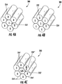
- the fiber bundle 250 is a seven fiber bundle 250 including a single central fiber surrounded circumferentially by six fibers. Such a configuration is illustrated in Figures 4A, 4B, and 4C . Although seven fibers as illustrated, other configurations and numbers of optical fibers may be included in the fiber bundle 250.
- the fiber(s) 252 receiving the lasers transmit the laser to an emitter end 254 and the light is emitted to the detection zone 202 in the case that no projector module 201 is included. Otherwise the light is incident on the parabolic mirror 203 and the parabolic mirror 203 focuses the light to the detection zone 202. Light scattered and/or fluoresced by particles in the detection zone 202 is returned to the fiber bundle 250, or the projector module 201, or lensed fiber bundle and enters detector fibers within the bundle 250. A portion of the detector fibers are UV/blue detector fibers and direct the light scattered and/or fluoresced from the detection zone 202 back to the lens 240.
- Light fluoresced from biological agents is the correct wavelength to pass through both dichroic mirrors 232, 230 and is directed to a bandpass filter 260.
- the bandpass filter is configured to allow light in the range of 430 nm to 470 nm to pass through. Practical implementations can tailor the pass through range of the bandpass filter to correspond to the correct light frequency of the biological agent being detected.
- one (or more) of the detector fibers 245 in the fiber optic bundle 250 is routed to an infrared or red smoke detector 280.
- Figures 4A, 4B and 4C illustrate exemplary fiber bundle configurations for the combined capability sensor 200 of Figure 3 .
- the center fiber 352 is an emitter fiber (labeled "E") and the outgoing light from the combined capability sensor 200 is focused into the emitter fiber 352 alone.
- the emitter fiber 352 is separated from the bundle 300 at the light source to allow for light to be directly coupled into the emitter fiber 352.
- the surrounding fibers 354 are detector fibers (labeled "D"), and receive the scattered and/or fluoresced light from the detection zone 202.
- Figure 4B illustrates an inverted configuration, where there is a single detector fiber 354 in the center of the fiber bundle 300, with the detector fiber 354 being surrounded by emitter fibers 352.
- the emitter fibers 352 would be removed from the bundle 300 at the light source and the light source would be directly coupled into the emitter fibers 352 in any conventional coupling configuration.
- the detector fiber 354 being in the center requires an additional splitting element downstream to split the light received in the detector fiber 354 between the fluorescence detector 270 and the infrared / red detector 280.
- Figure 4C illustrates an adaption of the example of Figure 4A and 4B , also including the single emitter/receiver 352 positioned in the center of the fiber bundle 300 with five of the surrounding detector fibers 354' being UV/blue detectors configured to direct the received light to the fluorescence sensor 270.
- One of the emitters 354" is a dedicated infrared or green/red detector (labeled "IR D") and directs the received light to the smoke detector 280.
- IR D dedicated infrared or green/red detector
- the five UV/blue detector fibers 354' in addition to the light collected by the center fiber eliminates the would-be blind spot generated by the emitter fiber 352, and results in no blind spot in the detection zone 202.
- the combination of features configured to direct light from the origination source to the detection zone is generally referred to as a "director", with the specific construction of the director varying depending on the embodiment being utilized.
Landscapes
- Physics & Mathematics (AREA)
- General Physics & Mathematics (AREA)
- Chemical & Material Sciences (AREA)
- Health & Medical Sciences (AREA)
- Analytical Chemistry (AREA)
- Life Sciences & Earth Sciences (AREA)
- Engineering & Computer Science (AREA)
- Biochemistry (AREA)
- General Health & Medical Sciences (AREA)
- Immunology (AREA)
- Pathology (AREA)
- Remote Sensing (AREA)
- Computer Networks & Wireless Communication (AREA)
- Radar, Positioning & Navigation (AREA)
- Dispersion Chemistry (AREA)
- Business, Economics & Management (AREA)
- Emergency Management (AREA)
- Nuclear Medicine, Radiotherapy & Molecular Imaging (AREA)
- Electromagnetism (AREA)
- Molecular Biology (AREA)
- Biomedical Technology (AREA)
- Fire-Detection Mechanisms (AREA)
- Investigating Or Analysing Materials By Optical Means (AREA)
- Optical Radar Systems And Details Thereof (AREA)
- Investigating, Analyzing Materials By Fluorescence Or Luminescence (AREA)
Abstract
Description
- The present disclosure relates generally to particulate detectors, such as smoke and/or biological particulate detectors, and more particularly to a combined capability detector for detecting smoke and biological particulates.
- Commercial building systems typically include systems for detecting smoke and other fire related hazards that may occur within the building. Such systems typically do not include capabilities for detecting and responding to hazardous biological or chemical agents. Further, some smoke detection systems cannot discriminate between smoke and biological particulates and can inadvertently trigger a fire response in the presence of a biological particulate.
- According to a first aspect of the invention, a combined capability sensor includes a first laser source and a second laser source, the first laser source being configured to emit light having a wavelength in at least one of an infrared spectrum and a visible spectrum and the second laser source being configured to emit light having a wavelength in a blue or ultraviolet spectrum, a director configured to direct the first and second laser source to a detection zone, a first sensor configured to detect scattered light originating from the first laser source, thereby detecting a presence of smoke in the detection zone, and a second sensor configured to detect fluoresced light originating from the second laser source, thereby detecting a presence of a biological agent in the detection zone.
- Optionally, the director comprises an off axis parabola including a laser light hole and a receiving surface.
- Optionally, the receiving surface is angled such that light scattered and/or fluoresced in the detection zone is directed to the first sensor and the second sensor.
- Optionally, light reflected by the receiving surface is directed to a dichroic filter, the dichroic filter being configured to pass light originating from the first laser source and reflect light originating from the second laser source.
- Optionally, the dichroic filter is configured to redirect reflected light to the second sensor.
- Optionally, light originating from the first laser source and light originating from the second laser source is directed to a dichroic combiner, and the dichroic combiner redirects the light to the detection zone.
- Optionally, the director comprises a first dichroic filter, a second dichroic filter and a lens, with the first dichroic filter the second dichroic filter and the lens being linearly arranged, the first dichroic filter reflecting light having a wavelength in the at least one of the infrared spectrum and the visible spectrum and the second dichroic filter reflecting light in the blue or ultraviolet wavelength, the second dichroic filter passing light in the at least one of the infrared spectrum and the visible spectrum.
- Optionally, each of the first dichroic filter and the second dichroic filter redirect light to the lens.
- Optionally, the lens is configured to focus received light on at least one emitter fiber of a fiber optic bundle.
- Optionally, the fiber optic bundle comprises a central fiber and a plurality of surrounding fibers disposed about the central fiber.
- Optionally, the central fiber is a detector fiber and the plurality of surrounding fibers are emitter fibers.
- Optionally, the central fiber is an emitter fiber and the plurality of surrounding fibers are detector fibers.
- Optionally, the central fiber is an emitter fiber and a detector fiber and the plurality of surrounding fibers are detector fibers.
- Optionally, the plurality of surrounding fibers includes at least one infrared and/or visible detector fiber and a remainder of the surrounding fibers comprise blue or ultraviolet detector fibers, and wherein the at least one infrared and/or visible detector fiber is connected to the first sensor.
- Optionally, each of the blue or ultraviolet detector fibers directs fluoresced light through the lens and the first dichroic filter and the second dichroic filter to the second sensor.
- Optionally, the second sensor comprises a bandpass filter and a lens, wherein the lens focuses light passed through the band pass filter on a sensing element.
- Optionally, the combined capability sensor further includes a projector module disposed at an end of the fiber optic bundle, the projector module including a parabolic mirror configured to direct light emitted from the fiber optic bundle to the detection zone.
- According to a second aspect of the invention, a building hazard detection system includes a plurality of combined capability sensors disposed throughout the building, each of the combined capability sensors being as described herein with reference to the first aspect of the invention, being configured to detected a presence of smoke and a presence of a biological agent; and a central building system in communication with each of the plurality of combined capability sensors. The building hazard detection system may comprise the building.
- According to a third aspect of the invention, a building hazard detection system includes a plurality of combined capability sensors disposed throughout the building, each of the combined capability sensors being configured to detected a presence of smoke and a presence of a biological agent, and a central building system in communication with each of the plurality of combined capability sensors.
- Optionally, each of the combined capability sensors includes a first laser source and a second laser source, the first laser source being configured to emit light having a wavelength in at least one of an infrared spectrum and a visible spectrum and the second laser source being configured to emit light have a wavelength in a blue or ultraviolet spectrum, a director configured to direct the first and second laser source to a detection zone, and a first sensor configured to detect scattered light originating from the first laser source, thereby detecting a presence of smoke in the detection zone, and a second sensor configured to detect fluoresced light originating from the second laser source, thereby detecting a presence of a biologic agent in the detection zone.
- Optionally, each of the combined capability sensors includes a first dichroic filter, a second dichroic filter and a lens, with the first dichroic filter the second dichroic filter and the lens being linearly arranged, the first dichroic filter reflecting light having a wavelength in the at least one of the infrared spectrum and the visible spectrum and the second dichroic filter reflecting light in the blue or ultraviolet wavelength, the second dichroic filter passing light in the at least one of the infrared spectrum and the visible spectrum.
- Optionally, each of the combined capability sensors is a combined capability sensor as described herein with reference to the first aspect of the invention.
- These and other features of the present invention can be best understood from the following specification and drawings provided by way of example only, the following of which is a brief description.
-
-
Figure 1 illustrates a high level schematic view of a building fire and biological detection system. -
Figures 2 schematically illustrates a combined capability sensor. -
Figure 3 schematically illustrates a combined capability sensor. -
Figure 4A illustrates a fiber bundle configuration for the combined capability sensor ofFigure 3 . -
Figure 4B illustrates a fiber bundle configuration for the combined capability sensor ofFigure 3 . -
Figure 4C illustrates a fiber bundle configuration for the combined capability sensor ofFigure 3 . -
Figure 1 schematically illustrates an exemplaryhazard detection system 20 for abuilding 10. Thehazard detection system 20 is connected tomultiple sensors 30 disposed throughoutrooms 12 of thebuilding 10. Each of thesensors 30 is connected to abase unit 22 via acommunication link 32. In some examples, thesensors 30 can include sensing nodes distributed about a zone (e.g. a room 12), with each of the nodes connected to a sensor package via a fiber optic network which couples the light from the nodes to the sensor package. Thecommunication link 32 is, in some examples, a wireless communication system. In alternative examples, thecommunication link 32 is a direct wired connection to thebase unit 22 through thebuilding 10. Alternative embodiments utilizing any other method of communicating between thesensors 30 and thebase unit 22 are envisioned and can be created with only minimal adaption of thesensors 30 disclosed herein. - Each of the
sensors 30 may provide a dual-role by being able to detect biological particulate via fluorescence enhanced LIDAR particulate detection, and being able to detect smoke via light scattering based detection. The dual sensing capabilities further allows thesensors 30, or thehazard detection system 20 to discriminate between the two types of hazards (based on the different characteristics each type presents as described below), and provide an appropriate alarm and/or other response when a hazard is detected. Fluorescence enhanced LIDAR uses fluorescence spectroscopy implemented over a short range for high sensitivity to target particles and/or a long range with localization of remote particles at relatively decreased sensitivity to target particles. - The biological particle detection portion of the
sensor 30 uses a UV or blue laser diode to excite the biological particles in the fluorescence excitation wavelength band, and fluorescence emission from the excited biological particles is detected. The smoke detection portion of thesensor 30 uses a visible or infrared laser diode light source with a pulsed LIDAR detection scheme. - The combined
capability sensor 30 provides a trigger for responding to a microbial or biological hazard at a low cost to enable an appropriate response from the building systems. - With continued reference to
Figure 1 ,Figure 2 schematically illustrates an exemplary free-space configuration for a combinedcapability sensor 100 configured to sense both smoke and biological hazards within adetection zone 102. The free-space configuration includes multiple components that are disposed relative to each other within thesensor 100. A first component is alight source 110 including a UV/blue laser 112 and a visible (green/red) or infrared (IR)laser diode 114. Each of theUV laser 112 and thelaser diode 114 are directed toward adichroic combiner 116. Thedichroic combiner 116 includes adichroic filter 118 that allows light of thelaser diode 114 frequency through, and reflects light of the UV/blue laser 112 frequency. By angling thedichroic filter 118, the light emitted from each of the UV/blue laser 112 and thelaser diode 114 is combined into and directed from thedichroic combiner 116 to an offaxis parabola 120. - The light from the
dichroic combiner 116 is passed through an alignedhole 122 in the offaxis parabola 120 and into thedetection zone 102. In some examples, a rotatingmirror 101 can be added after the parabola, thereby allowing the light to be swept across a larger area, increasing the size of thedetection zone 102. Any particulate(s) within thedetection zone 102 scatters and/or fluoresces the light back toward areceiving surface 124 of the offaxis parabola 120. Thereceiving surface 124 is angled such that light returned to the off axis parabola is directed toward asensor configuration 130. The light reflected from thereceiving surface 124 is directed to a fluorescence /lidar dichroic 132 within thesensor configuration 130. The fluorescence /lidar dichroic 132 allows scattered light from smoke and biological particles to pass through thedichroic 132 and into alidar detector 134. Thelidar detector 134 may include abandpass filter 135, apinhole 137 and adetector 139, although any other lidar detector configuration can be used to similar effect. The fluorescence / lidar dichroic 132 reflects the wavelengths fluoresced by biological agents, and the fluoresced light is passed to afluorescence detector 136 within thesensor configuration 130. Thefluorescence detector 136 includes afluorescence filter 131 and afluorescence detector 133 arranged linearly. - Due to the inclusion of the
hole 122 in theoff axis parabola 120, a detection blind spot is created in the sensedarea 102. The blind spot corresponds to the portion of the receivingsurface 124 where the pass throughhole 122 opens, as no light is reflected off the pass throughhole 122 opening. In some embodiments and/or uses, the presence of the blind spot is acceptable, for example in long range detection. In alternative examples, such as high sensitivity short-range detection, the blind spot results in unacceptable performance of the combinedcapability sensor 100, and an alternative configuration is utilized. - With continued reference to
Figures 1 and2 ,Figure 3 schematically illustrates an alternate combinedcapability sensor 200 configuration that does not result in a blind spot within adetection zone 202. The combinedcapability sensor 200 includes a green/red or infrared (IR)laser diode 210 configured to generate green/red or infrared light wavelengths for smoke detection. In one example, the green/red or IR diode is an approximately 130 mW diode. In other examples, other diodes configured to emit light in the green/red or IR wavelengths can be utilized. The laser fromlaser diode 210 is directed at alens 212. The combinedcapability sensor 200 also includes two blue or ultraviolet (UV)laser diodes 220. In one example, the blue orUV diodes 220 are approximately 70 mW diodes. In alternative examples, other diodes configured to emit light in the blue or UV wavelengths can be utilized. Light from the first laser diode is S-polarized and is then collimated usinglens 222, while light from the second UV/blue diode is P-polarized is then collimated usinglens 222. The distinctly polarized light is combined into a single beam, and redirected using apolarization beam combiner 224. In alternative examples, where a more powerful UV/blue laser diode is utilized, a single UV/blue laser diode can provide sufficient power and be directed without the utilization of thepolarization beam combiner 224. In such an example only a single UV/blue diode 222 is included and thepolarization lenses 222 and thepolarization combiner 224 are omitted. - IR or green/red wavelength light is directed through the
lens 212 to a firstdichroic reflector 230 that reflects the IR and green/red wavelengths, while allowing blue/UV wavelengths to pass through thedichroic reflector 230. The firstdichroic reflector 230 reflects and redirects the IR or green/red wavelength light towards a focusinglens 240 and through a seconddichroic reflector 232. The seconddichroic reflector 232 is configured to reflect UV/blue light of the wavelength emitted from the UV/blue lasers 220. The UV/blue laser reflected from the second dichroic 232 as well as the IR or green/red laser being passed through the second dichroic 232 is focused via alens 240. The light is focused into at least onefiber 252 of afiber bundle 250. Thefiber bundle 250 is a bundle of fiber optic cables configured to transmit light along the length of the cable. - A
projector module 201 is disposed at the end of thefiber bundle 250. The projector module includes aparabolic mirror 203 and facilitates the direction of the light emitted from thefiber bundle 250 to thedetection zone 202. In some examples, theparabolic mirror 203 is static and covers a statically defineddetection zone 202. In alternative examples, theparabolic mirror 203 is connected to a motor, or other rotational input, and facilitates sweeping the light output by thefiber bundle 250 thereby increasing the size of thedetection zone 202. In some examples, theprojector module 201 is configured to move the position of the fiber longitudinally relative to theparabolic mirror 201. The movement allows the sensor system to adjust focus or to achieve collimation. - In one example the
fiber bundle 250 is a sevenfiber bundle 250 including a single central fiber surrounded circumferentially by six fibers. Such a configuration is illustrated inFigures 4A, 4B, and 4C . Although seven fibers as illustrated, other configurations and numbers of optical fibers may be included in thefiber bundle 250. - In some alternative embodiments the fiber(s) 252 receiving the lasers transmit the laser to an
emitter end 254 and the light is emitted to thedetection zone 202 in the case that noprojector module 201 is included. Otherwise the light is incident on theparabolic mirror 203 and theparabolic mirror 203 focuses the light to thedetection zone 202. Light scattered and/or fluoresced by particles in thedetection zone 202 is returned to thefiber bundle 250, or theprojector module 201, or lensed fiber bundle and enters detector fibers within thebundle 250. A portion of the detector fibers are UV/blue detector fibers and direct the light scattered and/or fluoresced from thedetection zone 202 back to thelens 240. Light fluoresced from biological agents is the correct wavelength to pass through bothdichroic mirrors bandpass filter 260. In one example, the bandpass filter is configured to allow light in the range of 430 nm to 470 nm to pass through. Practical implementations can tailor the pass through range of the bandpass filter to correspond to the correct light frequency of the biological agent being detected. Once passed through thebandpass filter 260, the reflected light is focused onto afluorescence detector 270 via alens 272. - To provide for smoke detection, one (or more) of the detector fibers 245 in the
fiber optic bundle 250 is routed to an infrared orred smoke detector 280. - With continued reference to the example of
Figure 3 ,Figures 4A, 4B and 4C illustrate exemplary fiber bundle configurations for the combinedcapability sensor 200 ofFigure 3 . In the example ofFigure 4A , thecenter fiber 352 is an emitter fiber (labeled "E") and the outgoing light from the combinedcapability sensor 200 is focused into theemitter fiber 352 alone. In this example, theemitter fiber 352 is separated from thebundle 300 at the light source to allow for light to be directly coupled into theemitter fiber 352. The surroundingfibers 354 are detector fibers (labeled "D"), and receive the scattered and/or fluoresced light from thedetection zone 202. -
Figure 4B illustrates an inverted configuration, where there is asingle detector fiber 354 in the center of thefiber bundle 300, with thedetector fiber 354 being surrounded byemitter fibers 352. In this example, theemitter fibers 352 would be removed from thebundle 300 at the light source and the light source would be directly coupled into theemitter fibers 352 in any conventional coupling configuration. In the example ofFigure 4B , thedetector fiber 354 being in the center requires an additional splitting element downstream to split the light received in thedetector fiber 354 between thefluorescence detector 270 and the infrared /red detector 280. -
Figure 4C illustrates an adaption of the example ofFigure 4A and 4B , also including the single emitter/receiver 352 positioned in the center of thefiber bundle 300 with five of the surroundingdetector fibers 354' being UV/blue detectors configured to direct the received light to thefluorescence sensor 270. One of theemitters 354" is a dedicated infrared or green/red detector (labeled "IR D") and directs the received light to thesmoke detector 280. In the example ofFigure 4C , the five UV/blue detector fibers 354' in addition to the light collected by the center fiber eliminates the would-be blind spot generated by theemitter fiber 352, and results in no blind spot in thedetection zone 202. - With reference now to the examples of
Figures 2 and3 , the combination of features configured to direct light from the origination source to the detection zone is generally referred to as a "director", with the specific construction of the director varying depending on the embodiment being utilized. - It is further understood that any of the above described concepts can be used alone or in combination with any or all of the other above described concepts. Although an embodiment of this invention has been disclosed, a worker of ordinary skill in this art would recognize that certain modifications would come within the scope of this invention. For that reason, the following claims should be studied to determine the true scope and content of this invention.
- The following clauses recite features of the invention that may or may not presently be claimed, and which may serve as basis for amendment(s) and/or one or more divisional applications:
- 1. A combined capability sensor comprising:
- a first laser source and a second laser source, the first laser source being configured to emit light having a wavelength in at least one of an infrared spectrum and a visible spectrum and the second laser source being configured to emit light having a wavelength in a blue or ultraviolet spectrum;
- a director configured to direct the first and second laser source to a detection zone;
- a first sensor configured to detect scattered light originating from the first laser source, thereby detecting a presence of smoke in the detection zone; and
- a second sensor configured to detect fluoresced light originating from the second laser source, thereby detecting a presence of a biological agent in the detection zone.
- 2. The combined capability sensor of clause 1, wherein the director comprises an off axis parabola including a laser light hole and a receiving surface.
- 3. The combined capability sensor of clause 2, wherein the receiving surface is angled such that light scattered and/or fluoresced in the detection zone is directed to the first sensor and the second sensor.
- 4. The combined capability sensor of clause 3, wherein light reflected by the receiving surface is directed to a dichroic filter, the dichroic filter being configured to pass light originating from the first laser source and reflect light originating from the second laser source.
- 5. The combined capability sensor of clause 4, wherein the dichroic filter is configured to redirect reflected light to the second sensor.
- 6. The combined capability sensor of clause 1, wherein light originating from the first laser source and light originating from the second laser source is directed to a dichroic combiner, and the dichroic combiner redirects the light to the detection zone.
- 7. The combined capability sensor of clause 1, wherein the director comprises a first dichroic filter, a second dichroic filter and a lens, with the first dichroic filter the second dichroic filter and the lens being linearly arranged, the first dichroic filter reflecting light having a wavelength in the at least one of the infrared spectrum and the visible spectrum and the second dichroic filter reflecting light in the blue or ultraviolet wavelength, the second dichroic filter passing light in the at least one of the infrared spectrum and the visible spectrum.
- 8. The combined capability sensor of clause 7 wherein each of the first dichroic filter and the second dichroic filter redirect light to the lens.
- 9. The combined capability sensor of clause 8, wherein the lens is configured to focus received light on at least one emitter fiber of a fiber optic bundle.
- 10. The combined capability sensor of clause 9, wherein the fiber optic bundle comprise a central fiber and a plurality of surrounding fibers disposed about the central fiber.
- 11. The combined capability sensor of
clause 10, wherein the central fiber is a detector fiber and the plurality of surrounding fibers are emitter fibers. - 12. The combined capability sensor of
clause 10, wherein the central fiber is an emitter fiber and the plurality of surrounding fibers are detector fibers. - 13. The combined capability sensor of
clause 10, wherein the central fiber is an emitter fiber and a detector fiber and the plurality of surrounding fibers are detector fibers. - 14. The combined capability sensor of clause 13, wherein the plurality of surrounding fibers includes at least one infrared and/or visible detector fiber and a remainder of the surrounding fibers comprise blue or ultraviolet detector fibers, and wherein the at least one infrared and/or visible detector fiber is connected to the first sensor.
- 15. The combined capability sensor of clause 14, wherein each of the blue or ultraviolet detector fibers directs fluoresced light through the lens and the first dichroic filter and the second dichroic filter to the second sensor.
- 16. The combined capability sensor of clause 15, wherein the second sensor comprises a bandpass filter and a lens, wherein the lens focuses light passed through the band pass filter on a sensing element.
- 17. The combined capability sensor of clause 9, further comprising a projector module disposed at an end of the fiber optic bundle, the projector module including a parabolic mirror configured to direct light emitted from the fiber optic bundle to the detection zone.
- 18. A building hazard detection system comprising:
- a plurality of combined capability sensors disposed throughout the building, each of the combined capability sensors being configured to detected a presence of smoke and a presence of a biological agent; and
- a central building system in communication with each of the plurality of combined capability sensors.
- 19. The building hazard detection system of clause 18, wherein each of the combined capability sensors comprises:
- a first laser source and a second laser source, the first laser source being configured to emit light having a wavelength in at least one of an infrared spectrum and a visible spectrum and the second laser source being configured to emit light have a wavelength in a blue or ultraviolet spectrum;
- a director configured to direct the first and second laser source to a detection zone; and
- a first sensor configured to detect scattered light originating from the first laser source, thereby detecting a presence of smoke in the detection zone; and
- a second sensor configured to detect fluoresced light originating from the second laser source, thereby detecting a presence of a biologic agent in the detection zone.
- 20. The building hazard detection system of clause 19, wherein the director comprises a first dichroic filter, a second dichroic filter and a lens, with the first dichroic filter the second dichroic filter and the lens being linearly arranged, the first dichroic filter reflecting light having a wavelength in the at least one of the infrared spectrum and the visible spectrum and the second dichroic filter reflecting light in the blue or ultraviolet wavelength, the second dichroic filter passing light in the at least one of the infrared spectrum and the visible spectrum.
Claims (15)
- A combined capability sensor comprising:a first laser source and a second laser source, the first laser source being configured to emit light having a wavelength in at least one of an infrared spectrum and a visible spectrum and the second laser source being configured to emit light having a wavelength in a blue or ultraviolet spectrum;a director configured to direct the first and second laser source to a detection zone;a first sensor configured to detect scattered light originating from the first laser source, thereby detecting a presence of smoke in the detection zone; anda second sensor configured to detect fluoresced light originating from the second laser source, thereby detecting a presence of a biological agent in the detection zone.
- The combined capability sensor of claim 1, wherein the director comprises an off axis parabola including a laser light hole and a receiving surface.
- The combined capability sensor of claim 2, wherein the receiving surface is angled such that light scattered and/or fluoresced in the detection zone is directed to the first sensor and the second sensor.
- The combined capability sensor of claim 2 or 3, wherein light reflected by the receiving surface is directed to a dichroic filter, the dichroic filter being configured to pass light originating from the first laser source and reflect light originating from the second laser source; preferably
wherein the dichroic filter is configured to redirect reflected light to the second sensor. - The combined capability sensor of any preceding claim, wherein light originating from the first laser source and light originating from the second laser source is directed to a dichroic combiner, and the dichroic combiner redirects the light to the detection zone.
- The combined capability sensor of any preceding claim, wherein the director comprises a first dichroic filter, a second dichroic filter and a lens, with the first dichroic filter the second dichroic filter and the lens being linearly arranged, the first dichroic filter reflecting light having a wavelength in the at least one of the infrared spectrum and the visible spectrum and the second dichroic filter reflecting light in the blue or ultraviolet wavelength, the second dichroic filter passing light in the at least one of the infrared spectrum and the visible spectrum.
- The combined capability sensor of claim 6 wherein each of the first dichroic filter and the second dichroic filter redirect light to the lens.
- The combined capability sensor of claim 6 or 7, wherein the lens is configured to focus received light on at least one emitter fiber of a fiber optic bundle.
- The combined capability sensor of claim 8, wherein the fiber optic bundle comprise a central fiber and a plurality of surrounding fibers disposed about the central fiber.
- The combined capability sensor of claim 9, wherein the central fiber is a detector fiber and the plurality of surrounding fibers are emitter fibers.
- The combined capability sensor of claim 9, wherein the central fiber is an emitter fiber and the plurality of surrounding fibers are detector fibers.
- The combined capability sensor of claim 9, wherein the central fiber is an emitter fiber and a detector fiber and the plurality of surrounding fibers are detector fibers.
- The combined capability sensor of claim 12, wherein the plurality of surrounding fibers includes at least one infrared and/or visible detector fiber and a remainder of the surrounding fibers comprise blue or ultraviolet detector fibers, and wherein the at least one infrared and/or visible detector fiber is connected to the first sensor; preferably
wherein each of the blue or ultraviolet detector fibers directs fluoresced light through the lens and the first dichroic filter and the second dichroic filter to the second sensor; and more preferably
wherein the second sensor comprises a bandpass filter and a lens, wherein the lens focuses light passed through the band pass filter on a sensing element. - The combined capability sensor of any of claims 8 to 13, further comprising a projector module disposed at an end of the fiber optic bundle, the projector module including a parabolic mirror configured to direct light emitted from the fiber optic bundle to the detection zone.
- A building hazard detection system comprising:a plurality of combined capability sensors disposed throughout the building, each of the combined capability sensors being as claimed in any preceding claim and being configured to detected a presence of smoke and a presence of a biological agent; anda central building system in communication with each of the plurality of combined capability sensors.
Applications Claiming Priority (1)
| Application Number | Priority Date | Filing Date | Title |
|---|---|---|---|
| US201962943841P | 2019-12-05 | 2019-12-05 |
Publications (2)
| Publication Number | Publication Date |
|---|---|
| EP3832294A1 true EP3832294A1 (en) | 2021-06-09 |
| EP3832294B1 EP3832294B1 (en) | 2023-09-27 |
Family
ID=73726677
Family Applications (1)
| Application Number | Title | Priority Date | Filing Date |
|---|---|---|---|
| EP20211918.6A Active EP3832294B1 (en) | 2019-12-05 | 2020-12-04 | Fluorescence enhanced lidar based particulate detector |
Country Status (3)
| Country | Link |
|---|---|
| US (1) | US11474018B2 (en) |
| EP (1) | EP3832294B1 (en) |
| ES (1) | ES2958988T3 (en) |
Families Citing this family (4)
| Publication number | Priority date | Publication date | Assignee | Title |
|---|---|---|---|---|
| US11885718B2 (en) * | 2020-03-18 | 2024-01-30 | Rosemount Aerospace Inc. | Multi-fiber single lens optical ice detector |
| US12411242B2 (en) * | 2020-05-28 | 2025-09-09 | Faro Technologies, Inc. | Three-dimensional (3D) scanner with 3D aperture and tilted optical bandpass filter |
| US12025982B2 (en) | 2021-10-18 | 2024-07-02 | Rosemount Aerospace Inc. | Multiple angled field-of-view cloud sensor |
| US12039848B2 (en) * | 2021-10-28 | 2024-07-16 | Honeywell International Inc. | Non-coaxial systems, methods, and devices for detecting smoke |
Citations (6)
| Publication number | Priority date | Publication date | Assignee | Title |
|---|---|---|---|---|
| WO1999057529A1 (en) * | 1998-05-04 | 1999-11-11 | The Board Of Regents | Combined fluorescence and reflectance spectroscopy |
| US20060231771A1 (en) * | 2004-11-19 | 2006-10-19 | Science & Engineering Services, Inc. | Enhanced portable digital lidar system |
| US20150096170A1 (en) * | 2012-09-21 | 2015-04-09 | Nest Labs, Inc. | Adaptable hazard detector mounting plate and method therefor |
| US20150170490A1 (en) * | 2012-02-13 | 2015-06-18 | Thorn Security Limited | Combustion Product Detection |
| WO2018226567A1 (en) * | 2017-06-09 | 2018-12-13 | Carrier Corporation | Chamberless smoke detector with indoor air quality detection and monitoring |
| EP3561489A1 (en) * | 2018-04-27 | 2019-10-30 | Jeanología, S.L. | System and method for characterization of patterns marked on a fabric |
Family Cites Families (26)
| Publication number | Priority date | Publication date | Assignee | Title |
|---|---|---|---|---|
| US5999250A (en) * | 1997-03-17 | 1999-12-07 | Tsi Corporation | System for detecting fluorescing components in aerosols |
| US7352339B2 (en) * | 1997-08-26 | 2008-04-01 | Philips Solid-State Lighting Solutions | Diffuse illumination systems and methods |
| DE19835797C2 (en) | 1998-08-07 | 2003-01-23 | Deutsch Zentr Luft & Raumfahrt | Method for detecting smoke using a lidar system |
| US6593582B2 (en) | 2001-05-11 | 2003-07-15 | Science & Engineering Services, Inc. | Portable digital lidar system |
| AU2002367966B2 (en) * | 2001-11-07 | 2008-06-19 | S3I L.L.C. | System and method for detecting and classifying biological particles |
| US8024135B2 (en) | 2004-04-13 | 2011-09-20 | Science & Engineering Services, Inc. | Ultraviolet lidar for detection of biological warfare agents |
| CN100595564C (en) * | 2004-07-30 | 2010-03-24 | 百维吉伦特系统有限公司 | Pathogen and particle detector systems and methods |
| EP2044420A2 (en) * | 2006-07-17 | 2009-04-08 | Max Wiki | Analytical system comprising an arrangement for temporally variable spatial light modulation and detection method implemented thereby |
| US8358411B2 (en) * | 2008-12-18 | 2013-01-22 | Biovigilant Systems, Inc. | Integrated microbial collector |
| CN102116729A (en) * | 2010-01-06 | 2011-07-06 | 北京汇丰隆生物科技发展有限公司 | Light path system for continuous laser particle analyzer |
| CN101858847B (en) * | 2010-05-20 | 2013-06-12 | 中国科学院上海光学精密机械研究所 | Double-channel real-time bioaerosol monitoring method and device |
| US9915609B1 (en) | 2012-04-29 | 2018-03-13 | Valor Fire Safety, Llc | System and method of smoke detection using multiple wavelengths of light |
| GB2511809B (en) | 2013-03-14 | 2015-12-23 | Kidde Tech Inc | Thermal event detection and notification system |
| US9600989B2 (en) | 2013-09-12 | 2017-03-21 | Google Inc. | Detector unit with multiple integrated sensing systems and visually pleasing housing |
| EP2848913A1 (en) | 2013-09-12 | 2015-03-18 | Siemens Schweiz AG | Detection device for detecting fine dust |
| CN105849787B (en) * | 2013-10-30 | 2019-02-15 | 瓦洛尔消防安全有限责任公司 | Smoke detector with external sampling volume and ambient light suppression |
| WO2015151502A1 (en) | 2014-04-03 | 2015-10-08 | パナソニックIpマネジメント株式会社 | Particle-detecting sensor, dust sensor, smoke detector, air purifier, fan, and air conditioner |
| EP3167309B1 (en) | 2014-07-11 | 2021-02-17 | Carrier Corporation | Encoder-less lidar positioning technique for detection and alarm |
| EP3029646B1 (en) | 2014-12-01 | 2019-01-30 | Siemens Schweiz AG | Scattered light smoke detector with a two-colour light emitting diode |
| EP3131073A1 (en) | 2015-08-13 | 2017-02-15 | Siemens Schweiz AG | Smoke detection unit having light emitting diodes and photoreceiver, and with an led chip in the light emitting diode and photosensor for determining an aging level and/or a light current compensation value, and light emitting diode |
| EP3131077B1 (en) | 2015-08-13 | 2017-10-18 | Siemens Schweiz AG | Optical smoke detection unit for a smoke detector with two optically coupled light emitting diodes and with a connected control unit for deriving aging information and smoke detector |
| JP6620983B2 (en) * | 2015-12-28 | 2019-12-18 | パナソニックIpマネジメント株式会社 | Particle detection sensor |
| US9651485B1 (en) | 2015-12-31 | 2017-05-16 | Google Inc. | Systems and methods for using multiple light detecting optoelectronic components of a hazard detection system to determine a smoke condition of an environment |
| US10871452B2 (en) | 2016-06-15 | 2020-12-22 | Kidde Technologies, Inc. | Systems and methods for chamberless smoke detection and indoor air quality monitoring |
| EP3483585B1 (en) | 2017-11-13 | 2022-06-29 | Carrier Corporation | Air particulate detection system |
| EP3584775A1 (en) | 2018-06-19 | 2019-12-25 | Siemens Schweiz AG | Solderable, in particular single-element optical light guide module for scattered light smoke detection and smoke detecting block, smoke detection module and scattered-light smoke detector |
-
2020
- 2020-11-23 US US17/101,121 patent/US11474018B2/en active Active
- 2020-12-04 ES ES20211918T patent/ES2958988T3/en active Active
- 2020-12-04 EP EP20211918.6A patent/EP3832294B1/en active Active
Patent Citations (6)
| Publication number | Priority date | Publication date | Assignee | Title |
|---|---|---|---|---|
| WO1999057529A1 (en) * | 1998-05-04 | 1999-11-11 | The Board Of Regents | Combined fluorescence and reflectance spectroscopy |
| US20060231771A1 (en) * | 2004-11-19 | 2006-10-19 | Science & Engineering Services, Inc. | Enhanced portable digital lidar system |
| US20150170490A1 (en) * | 2012-02-13 | 2015-06-18 | Thorn Security Limited | Combustion Product Detection |
| US20150096170A1 (en) * | 2012-09-21 | 2015-04-09 | Nest Labs, Inc. | Adaptable hazard detector mounting plate and method therefor |
| WO2018226567A1 (en) * | 2017-06-09 | 2018-12-13 | Carrier Corporation | Chamberless smoke detector with indoor air quality detection and monitoring |
| EP3561489A1 (en) * | 2018-04-27 | 2019-10-30 | Jeanología, S.L. | System and method for characterization of patterns marked on a fabric |
Also Published As
| Publication number | Publication date |
|---|---|
| US20210172851A1 (en) | 2021-06-10 |
| EP3832294B1 (en) | 2023-09-27 |
| US11474018B2 (en) | 2022-10-18 |
| ES2958988T3 (en) | 2024-02-19 |
Similar Documents
| Publication | Publication Date | Title |
|---|---|---|
| EP3832294B1 (en) | Fluorescence enhanced lidar based particulate detector | |
| US7005645B2 (en) | Apparatus and methods for launching and receiving a broad wavelength range source | |
| EP3407049B1 (en) | Measuring optical array polarity, power, and loss using a position sensing detector and photodetector-equipped optical testing device | |
| US9207170B2 (en) | Gas detector system | |
| CN1261972A (en) | Smoke detector | |
| JPH10276132A (en) | Optical transceiver and optical transmission / reception method using common optical path for transmission and reception | |
| EP0959325A2 (en) | Photoelectric switch, fiber-type photoelectric switch, and color discrimination sensor | |
| JPH0634540A (en) | Fluid-body contamination monitor | |
| US4459024A (en) | Method and apparatus for light detection and ranging for use in visually obstructed areas | |
| US7030365B2 (en) | Emitter-detector assembly for a reflex photoelectric object detection system | |
| JP2004504618A (en) | Method and apparatus for optically measuring distance or velocity | |
| CN110658175A (en) | Mobile phone fusion system of Raman spectrometer and thermal infrared imager | |
| US6723989B1 (en) | Remote emissions sensing system and method with a composite beam of IR and UV radiation that is not split for detection | |
| JP7194883B2 (en) | FAILURE DETECTION DEVICE, LASER PROCESSING SYSTEM AND FAILURE DETECTION METHOD | |
| JP2761083B2 (en) | Multi-wavelength extinction smoke detector | |
| JP3413967B2 (en) | Fluorescence microscope | |
| US20030090818A1 (en) | Co-aligned receiver and transmitter for wireless link | |
| JPH05107100A (en) | Interface detection method and device | |
| US7336903B2 (en) | Optical wireless transmission apparatus | |
| JPH09282577A (en) | Gas detector | |
| US4422181A (en) | Bi-directional fibre-optic coupler | |
| EP4198480B1 (en) | An optical integrity monitoring apparatus for an optical system | |
| JPS59204726A (en) | Flame detector | |
| WO1995002179B1 (en) | Misalignment detection apparatus for transmissometer with underfilled reflector | |
| EP1151275B1 (en) | Remote emissions sensing system and method with a composite beam of ir and uv radiation that is not split for detection |
Legal Events
| Date | Code | Title | Description |
|---|---|---|---|
| PUAI | Public reference made under article 153(3) epc to a published international application that has entered the european phase |
Free format text: ORIGINAL CODE: 0009012 |
|
| STAA | Information on the status of an ep patent application or granted ep patent |
Free format text: STATUS: THE APPLICATION HAS BEEN PUBLISHED |
|
| AK | Designated contracting states |
Kind code of ref document: A1 Designated state(s): AL AT BE BG CH CY CZ DE DK EE ES FI FR GB GR HR HU IE IS IT LI LT LU LV MC MK MT NL NO PL PT RO RS SE SI SK SM TR |
|
| STAA | Information on the status of an ep patent application or granted ep patent |
Free format text: STATUS: REQUEST FOR EXAMINATION WAS MADE |
|
| 17P | Request for examination filed |
Effective date: 20211209 |
|
| RBV | Designated contracting states (corrected) |
Designated state(s): AL AT BE BG CH CY CZ DE DK EE ES FI FR GB GR HR HU IE IS IT LI LT LU LV MC MK MT NL NO PL PT RO RS SE SI SK SM TR |
|
| REG | Reference to a national code |
Ref country code: DE Ref legal event code: R079 Free format text: PREVIOUS MAIN CLASS: G01N0021640000 Ipc: G01N0021470000 Ref country code: DE Ref legal event code: R079 Ref document number: 602020018228 Country of ref document: DE Free format text: PREVIOUS MAIN CLASS: G01N0021640000 Ipc: G01N0021470000 |
|
| GRAP | Despatch of communication of intention to grant a patent |
Free format text: ORIGINAL CODE: EPIDOSNIGR1 |
|
| STAA | Information on the status of an ep patent application or granted ep patent |
Free format text: STATUS: GRANT OF PATENT IS INTENDED |
|
| RIC1 | Information provided on ipc code assigned before grant |
Ipc: G01N 15/00 20060101ALN20230329BHEP Ipc: G01N 21/17 20060101ALN20230329BHEP Ipc: G08B 17/107 20060101ALI20230329BHEP Ipc: G01S 17/88 20060101ALI20230329BHEP Ipc: G01S 7/481 20060101ALI20230329BHEP Ipc: G01N 15/14 20060101ALI20230329BHEP Ipc: G01N 21/64 20060101ALI20230329BHEP Ipc: G01N 21/53 20060101ALI20230329BHEP Ipc: G01N 21/47 20060101AFI20230329BHEP |
|
| INTG | Intention to grant announced |
Effective date: 20230418 |
|
| GRAS | Grant fee paid |
Free format text: ORIGINAL CODE: EPIDOSNIGR3 |
|
| GRAA | (expected) grant |
Free format text: ORIGINAL CODE: 0009210 |
|
| STAA | Information on the status of an ep patent application or granted ep patent |
Free format text: STATUS: THE PATENT HAS BEEN GRANTED |
|
| AK | Designated contracting states |
Kind code of ref document: B1 Designated state(s): AL AT BE BG CH CY CZ DE DK EE ES FI FR GB GR HR HU IE IS IT LI LT LU LV MC MK MT NL NO PL PT RO RS SE SI SK SM TR |
|
| REG | Reference to a national code |
Ref country code: GB Ref legal event code: FG4D |
|
| REG | Reference to a national code |
Ref country code: CH Ref legal event code: EP |
|
| REG | Reference to a national code |
Ref country code: DE Ref legal event code: R096 Ref document number: 602020018228 Country of ref document: DE |
|
| REG | Reference to a national code |
Ref country code: IE Ref legal event code: FG4D |
|
| REG | Reference to a national code |
Ref country code: LT Ref legal event code: MG9D |
|
| PG25 | Lapsed in a contracting state [announced via postgrant information from national office to epo] |
Ref country code: GR Free format text: LAPSE BECAUSE OF FAILURE TO SUBMIT A TRANSLATION OF THE DESCRIPTION OR TO PAY THE FEE WITHIN THE PRESCRIBED TIME-LIMIT Effective date: 20231228 |
|
| PG25 | Lapsed in a contracting state [announced via postgrant information from national office to epo] |
Ref country code: SE Free format text: LAPSE BECAUSE OF FAILURE TO SUBMIT A TRANSLATION OF THE DESCRIPTION OR TO PAY THE FEE WITHIN THE PRESCRIBED TIME-LIMIT Effective date: 20230927 Ref country code: RS Free format text: LAPSE BECAUSE OF FAILURE TO SUBMIT A TRANSLATION OF THE DESCRIPTION OR TO PAY THE FEE WITHIN THE PRESCRIBED TIME-LIMIT Effective date: 20230927 Ref country code: NO Free format text: LAPSE BECAUSE OF FAILURE TO SUBMIT A TRANSLATION OF THE DESCRIPTION OR TO PAY THE FEE WITHIN THE PRESCRIBED TIME-LIMIT Effective date: 20231227 Ref country code: LV Free format text: LAPSE BECAUSE OF FAILURE TO SUBMIT A TRANSLATION OF THE DESCRIPTION OR TO PAY THE FEE WITHIN THE PRESCRIBED TIME-LIMIT Effective date: 20230927 Ref country code: LT Free format text: LAPSE BECAUSE OF FAILURE TO SUBMIT A TRANSLATION OF THE DESCRIPTION OR TO PAY THE FEE WITHIN THE PRESCRIBED TIME-LIMIT Effective date: 20230927 Ref country code: HR Free format text: LAPSE BECAUSE OF FAILURE TO SUBMIT A TRANSLATION OF THE DESCRIPTION OR TO PAY THE FEE WITHIN THE PRESCRIBED TIME-LIMIT Effective date: 20230927 Ref country code: GR Free format text: LAPSE BECAUSE OF FAILURE TO SUBMIT A TRANSLATION OF THE DESCRIPTION OR TO PAY THE FEE WITHIN THE PRESCRIBED TIME-LIMIT Effective date: 20231228 Ref country code: FI Free format text: LAPSE BECAUSE OF FAILURE TO SUBMIT A TRANSLATION OF THE DESCRIPTION OR TO PAY THE FEE WITHIN THE PRESCRIBED TIME-LIMIT Effective date: 20230927 |
|
| REG | Reference to a national code |
Ref country code: NL Ref legal event code: MP Effective date: 20230927 |
|
| REG | Reference to a national code |
Ref country code: AT Ref legal event code: MK05 Ref document number: 1615854 Country of ref document: AT Kind code of ref document: T Effective date: 20230927 |
|
| REG | Reference to a national code |
Ref country code: ES Ref legal event code: FG2A Ref document number: 2958988 Country of ref document: ES Kind code of ref document: T3 Effective date: 20240219 |
|
| PG25 | Lapsed in a contracting state [announced via postgrant information from national office to epo] |
Ref country code: NL Free format text: LAPSE BECAUSE OF FAILURE TO SUBMIT A TRANSLATION OF THE DESCRIPTION OR TO PAY THE FEE WITHIN THE PRESCRIBED TIME-LIMIT Effective date: 20230927 |
|
| PG25 | Lapsed in a contracting state [announced via postgrant information from national office to epo] |
Ref country code: IS Free format text: LAPSE BECAUSE OF FAILURE TO SUBMIT A TRANSLATION OF THE DESCRIPTION OR TO PAY THE FEE WITHIN THE PRESCRIBED TIME-LIMIT Effective date: 20240127 |
|
| PG25 | Lapsed in a contracting state [announced via postgrant information from national office to epo] |
Ref country code: AT Free format text: LAPSE BECAUSE OF FAILURE TO SUBMIT A TRANSLATION OF THE DESCRIPTION OR TO PAY THE FEE WITHIN THE PRESCRIBED TIME-LIMIT Effective date: 20230927 |
|
| PG25 | Lapsed in a contracting state [announced via postgrant information from national office to epo] |
Ref country code: SM Free format text: LAPSE BECAUSE OF FAILURE TO SUBMIT A TRANSLATION OF THE DESCRIPTION OR TO PAY THE FEE WITHIN THE PRESCRIBED TIME-LIMIT Effective date: 20230927 Ref country code: RO Free format text: LAPSE BECAUSE OF FAILURE TO SUBMIT A TRANSLATION OF THE DESCRIPTION OR TO PAY THE FEE WITHIN THE PRESCRIBED TIME-LIMIT Effective date: 20230927 Ref country code: IS Free format text: LAPSE BECAUSE OF FAILURE TO SUBMIT A TRANSLATION OF THE DESCRIPTION OR TO PAY THE FEE WITHIN THE PRESCRIBED TIME-LIMIT Effective date: 20240127 Ref country code: EE Free format text: LAPSE BECAUSE OF FAILURE TO SUBMIT A TRANSLATION OF THE DESCRIPTION OR TO PAY THE FEE WITHIN THE PRESCRIBED TIME-LIMIT Effective date: 20230927 Ref country code: CZ Free format text: LAPSE BECAUSE OF FAILURE TO SUBMIT A TRANSLATION OF THE DESCRIPTION OR TO PAY THE FEE WITHIN THE PRESCRIBED TIME-LIMIT Effective date: 20230927 Ref country code: AT Free format text: LAPSE BECAUSE OF FAILURE TO SUBMIT A TRANSLATION OF THE DESCRIPTION OR TO PAY THE FEE WITHIN THE PRESCRIBED TIME-LIMIT Effective date: 20230927 Ref country code: PT Free format text: LAPSE BECAUSE OF FAILURE TO SUBMIT A TRANSLATION OF THE DESCRIPTION OR TO PAY THE FEE WITHIN THE PRESCRIBED TIME-LIMIT Effective date: 20240129 Ref country code: SK Free format text: LAPSE BECAUSE OF FAILURE TO SUBMIT A TRANSLATION OF THE DESCRIPTION OR TO PAY THE FEE WITHIN THE PRESCRIBED TIME-LIMIT Effective date: 20230927 |
|
| PG25 | Lapsed in a contracting state [announced via postgrant information from national office to epo] |
Ref country code: PL Free format text: LAPSE BECAUSE OF FAILURE TO SUBMIT A TRANSLATION OF THE DESCRIPTION OR TO PAY THE FEE WITHIN THE PRESCRIBED TIME-LIMIT Effective date: 20230927 Ref country code: IT Free format text: LAPSE BECAUSE OF FAILURE TO SUBMIT A TRANSLATION OF THE DESCRIPTION OR TO PAY THE FEE WITHIN THE PRESCRIBED TIME-LIMIT Effective date: 20230927 |
|
| REG | Reference to a national code |
Ref country code: DE Ref legal event code: R097 Ref document number: 602020018228 Country of ref document: DE |
|
| REG | Reference to a national code |
Ref country code: DE Ref legal event code: R119 Ref document number: 602020018228 Country of ref document: DE |
|
| PG25 | Lapsed in a contracting state [announced via postgrant information from national office to epo] |
Ref country code: DK Free format text: LAPSE BECAUSE OF FAILURE TO SUBMIT A TRANSLATION OF THE DESCRIPTION OR TO PAY THE FEE WITHIN THE PRESCRIBED TIME-LIMIT Effective date: 20230927 |
|
| PG25 | Lapsed in a contracting state [announced via postgrant information from national office to epo] |
Ref country code: DK Free format text: LAPSE BECAUSE OF FAILURE TO SUBMIT A TRANSLATION OF THE DESCRIPTION OR TO PAY THE FEE WITHIN THE PRESCRIBED TIME-LIMIT Effective date: 20230927 |
|
| REG | Reference to a national code |
Ref country code: CH Ref legal event code: PL |
|
| PLBE | No opposition filed within time limit |
Free format text: ORIGINAL CODE: 0009261 |
|
| STAA | Information on the status of an ep patent application or granted ep patent |
Free format text: STATUS: NO OPPOSITION FILED WITHIN TIME LIMIT |
|
| PG25 | Lapsed in a contracting state [announced via postgrant information from national office to epo] |
Ref country code: LU Free format text: LAPSE BECAUSE OF NON-PAYMENT OF DUE FEES Effective date: 20231204 |
|
| PG25 | Lapsed in a contracting state [announced via postgrant information from national office to epo] |
Ref country code: MC Free format text: LAPSE BECAUSE OF FAILURE TO SUBMIT A TRANSLATION OF THE DESCRIPTION OR TO PAY THE FEE WITHIN THE PRESCRIBED TIME-LIMIT Effective date: 20230927 |
|
| REG | Reference to a national code |
Ref country code: BE Ref legal event code: MM Effective date: 20231231 |
|
| PG25 | Lapsed in a contracting state [announced via postgrant information from national office to epo] |
Ref country code: MC Free format text: LAPSE BECAUSE OF FAILURE TO SUBMIT A TRANSLATION OF THE DESCRIPTION OR TO PAY THE FEE WITHIN THE PRESCRIBED TIME-LIMIT Effective date: 20230927 Ref country code: LU Free format text: LAPSE BECAUSE OF NON-PAYMENT OF DUE FEES Effective date: 20231204 |
|
| 26N | No opposition filed |
Effective date: 20240628 |
|
| REG | Reference to a national code |
Ref country code: IE Ref legal event code: MM4A |
|
| PG25 | Lapsed in a contracting state [announced via postgrant information from national office to epo] |
Ref country code: DE Free format text: LAPSE BECAUSE OF NON-PAYMENT OF DUE FEES Effective date: 20240702 Ref country code: IE Free format text: LAPSE BECAUSE OF NON-PAYMENT OF DUE FEES Effective date: 20231204 |
|
| PG25 | Lapsed in a contracting state [announced via postgrant information from national office to epo] |
Ref country code: BE Free format text: LAPSE BECAUSE OF NON-PAYMENT OF DUE FEES Effective date: 20231231 |
|
| PG25 | Lapsed in a contracting state [announced via postgrant information from national office to epo] |
Ref country code: CH Free format text: LAPSE BECAUSE OF NON-PAYMENT OF DUE FEES Effective date: 20231231 |
|
| PG25 | Lapsed in a contracting state [announced via postgrant information from national office to epo] |
Ref country code: SI Free format text: LAPSE BECAUSE OF FAILURE TO SUBMIT A TRANSLATION OF THE DESCRIPTION OR TO PAY THE FEE WITHIN THE PRESCRIBED TIME-LIMIT Effective date: 20230927 |
|
| PG25 | Lapsed in a contracting state [announced via postgrant information from national office to epo] |
Ref country code: SI Free format text: LAPSE BECAUSE OF FAILURE TO SUBMIT A TRANSLATION OF THE DESCRIPTION OR TO PAY THE FEE WITHIN THE PRESCRIBED TIME-LIMIT Effective date: 20230927 Ref country code: IE Free format text: LAPSE BECAUSE OF NON-PAYMENT OF DUE FEES Effective date: 20231204 Ref country code: DE Free format text: LAPSE BECAUSE OF NON-PAYMENT OF DUE FEES Effective date: 20240702 Ref country code: CH Free format text: LAPSE BECAUSE OF NON-PAYMENT OF DUE FEES Effective date: 20231231 Ref country code: BE Free format text: LAPSE BECAUSE OF NON-PAYMENT OF DUE FEES Effective date: 20231231 |
|
| PG25 | Lapsed in a contracting state [announced via postgrant information from national office to epo] |
Ref country code: BG Free format text: LAPSE BECAUSE OF FAILURE TO SUBMIT A TRANSLATION OF THE DESCRIPTION OR TO PAY THE FEE WITHIN THE PRESCRIBED TIME-LIMIT Effective date: 20230927 |
|
| PG25 | Lapsed in a contracting state [announced via postgrant information from national office to epo] |
Ref country code: BG Free format text: LAPSE BECAUSE OF FAILURE TO SUBMIT A TRANSLATION OF THE DESCRIPTION OR TO PAY THE FEE WITHIN THE PRESCRIBED TIME-LIMIT Effective date: 20230927 |
|
| PG25 | Lapsed in a contracting state [announced via postgrant information from national office to epo] |
Ref country code: CY Free format text: LAPSE BECAUSE OF FAILURE TO SUBMIT A TRANSLATION OF THE DESCRIPTION OR TO PAY THE FEE WITHIN THE PRESCRIBED TIME-LIMIT; INVALID AB INITIO Effective date: 20201204 |
|
| PG25 | Lapsed in a contracting state [announced via postgrant information from national office to epo] |
Ref country code: HU Free format text: LAPSE BECAUSE OF FAILURE TO SUBMIT A TRANSLATION OF THE DESCRIPTION OR TO PAY THE FEE WITHIN THE PRESCRIBED TIME-LIMIT; INVALID AB INITIO Effective date: 20201204 |
|
| PG25 | Lapsed in a contracting state [announced via postgrant information from national office to epo] |
Ref country code: TR Free format text: LAPSE BECAUSE OF FAILURE TO SUBMIT A TRANSLATION OF THE DESCRIPTION OR TO PAY THE FEE WITHIN THE PRESCRIBED TIME-LIMIT Effective date: 20230927 |
|
| PGFP | Annual fee paid to national office [announced via postgrant information from national office to epo] |
Ref country code: GB Payment date: 20251120 Year of fee payment: 6 |
|
| PGFP | Annual fee paid to national office [announced via postgrant information from national office to epo] |
Ref country code: FR Payment date: 20251120 Year of fee payment: 6 |
|
| PGFP | Annual fee paid to national office [announced via postgrant information from national office to epo] |
Ref country code: ES Payment date: 20260102 Year of fee payment: 6 |