EP3832212A1 - An exhaust hood arranged together with the cooktop - Google Patents
An exhaust hood arranged together with the cooktop Download PDFInfo
- Publication number
- EP3832212A1 EP3832212A1 EP20210335.4A EP20210335A EP3832212A1 EP 3832212 A1 EP3832212 A1 EP 3832212A1 EP 20210335 A EP20210335 A EP 20210335A EP 3832212 A1 EP3832212 A1 EP 3832212A1
- Authority
- EP
- European Patent Office
- Prior art keywords
- cooktop
- exhaust hood
- discharge
- discharge hole
- fan
- Prior art date
- Legal status (The legal status is an assumption and is not a legal conclusion. Google has not performed a legal analysis and makes no representation as to the accuracy of the status listed.)
- Withdrawn
Links
- 239000002699 waste material Substances 0.000 claims abstract description 19
- 238000010438 heat treatment Methods 0.000 claims abstract description 8
- 238000007789 sealing Methods 0.000 claims description 4
- 239000007788 liquid Substances 0.000 description 6
- 238000010411 cooking Methods 0.000 description 5
- 238000004140 cleaning Methods 0.000 description 3
- 239000000919 ceramic Substances 0.000 description 1
- 239000011521 glass Substances 0.000 description 1
- 238000000034 method Methods 0.000 description 1
Images

Classifications
-
- F—MECHANICAL ENGINEERING; LIGHTING; HEATING; WEAPONS; BLASTING
- F24—HEATING; RANGES; VENTILATING
- F24C—DOMESTIC STOVES OR RANGES ; DETAILS OF DOMESTIC STOVES OR RANGES, OF GENERAL APPLICATION
- F24C15/00—Details
- F24C15/20—Removing cooking fumes
- F24C15/2042—Devices for removing cooking fumes structurally associated with a cooking range e.g. downdraft
Definitions
- the present invention relates to an exhaust hood which draws the air flow downwards from the cooktop and which is arranged together with the cooktop.
- exhaust hoods which are integrated especially with cooktops are known.
- a fan which carries out the sucking function is provided under the counter whereon the cooktop plate is placed.
- the air is sucked through an opening on the cooktop plate or the counter adjacent to the cooktop plate such that an air flow is created on the cooktop and the vapor originating from vessels such as pot, etc. placed on the heating member is sucked by the fan under the counter.
- the waste container since the waste container has a limited volume, the emptying and cleaning process must be frequently repeated. Since the waste container is positioned under the counter, it is very difficult for the user to remove and replace the same. Moreover, very important safety risks may arise if the liquid collected in the waste container gets in contact especially with electrical components.
- an exhaust hood is disclosed, which is disposed so as to be adjacent to the cooktop plate such that an air flow is sucked downwards in the vicinity of the cooktop plate.
- the aim of the present invention is the realization of an exhaust hood which is arranged together with the cooktop, wherein the air sucked downwards from the cooktop is discharged to the outside in an efficient and safe manner.
- the exhaust hood realized in order to attain the aim of the present invention, explicated in the first claim and the respective claims thereof, is arranged together with a cooktop having at least one heating member thereon, and comprises at least one opening which is provided on the cooktop or adjacent thereto; a fan which is provided under the cooktop and which sucks air from over the cooktop through the opening; a casing under the cooktop wherein the fan is disposed; a discharge hole which is provided on the base of the casing; a lid which opens/closes the discharge hole; and a discharge member which is connected to the discharge hole at one end and which provides the discharge of the waste passing through the discharge hole outside the exhaust hood.
- the discharge member is a discharge hose with one end connected to the discharge hole and the other end to the main drain. Since the exhaust hood is directly connected to the main drain, the need for frequently cleaning is eliminated, thus providing savings in time. Moreover, the risk of any liquid overflowing and causing damage to the device or the environment wherein the device is installed is eliminated.
- the discharge member is a waste collection tank.
- the waste collection tank is connected to the main drain by means of the discharge hose.
- the lid opening/closing the discharge hole is a spring lid and can open/close depending on the weight of the liquid. Thus, any unpleasant factors such as odor from the main drain are prevented.
- a rubber gasket is preferably used for ensuring the leakproofing of the discharge hole.
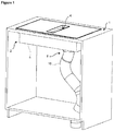
- the exhaust hood (2) is arranged together with a cooktop (1) having at least one heating member thereon, and comprises at least one opening (4) which is provided on the cooktop (1) or adjacent thereto; a fan (3) which is provided under the cooktop (1) and which sucks air from over the cooktop (1) through the opening (4); a casing (5) under the cooktop (1) wherein the fan (3) is disposed; a discharge hole (6) which is provided on the base of the casing (5); a lid (7) which opens/closes the discharge hole (6); and a discharge member (8) which is connected to the discharge hole (6) at one end and which provides the discharge of the waste passing through the discharge hole (6) outside the exhaust hood (2) ( Figure 1 and Figure 2 ).
- the cooktop (1) is produced from for example glass or ceramic, and comprises heating members in different numbers, geometries and structures.
- the heating member is a radiant heater or inductor.
- the exhaust hood (2) is almost a part of the cooktop (1) which is arranged almost adjacent to the cooktop (1), or is closed by means of an additional lid.
- the exhaust hood (2) comprises a fan (3) designed as a suction fan (3).
- the fan (3) starts to operate and the vapor leaving the cooking vessel placed onto the cooktop (1) is sucked through the opening (4) into the casing (5) with the operation of the fan (3).
- the vapor and the condensed liquid reaches the discharge hole (6) so as to be transferred out of the exhaust hood (2) via the discharge member (8).
- the discharge member (8) is a discharge hose (10) with one end connected to the discharge hole (6) and the other end to the main drain.
- the fan (3) starts to operate and the vapor leaving the cooking vessel placed onto the cooktop (1) is sucked through the opening (4) into the casing (5) with the operation of the fan (3) so as to reach the discharge hole (6) and to be discharged to the main drain by means of the discharge hose (10). Since the exhaust hood (2) is directly connected to the main drain, the need for frequently cleaning is eliminated, thus providing savings in time. Moreover, the risk of any liquid overflowing and causing damage to the device or the environment wherein the device is installed is eliminated ( Figure 4 and Figure 5 ).
- the discharge member (8) is a waste collection tank (9) ( Figure 6 ).
- the waste collection tank (9) is connected to the main drain by means of the discharge hose (10).
- the lid (7) opening/closing the discharge hole (6) is a spring lid (7) and can open/close depending on the weight of the liquid. Thus, any unpleasant factors such as odor from the main drain are prevented ( Figure 3 ).
- a sealing member (11) placed on the wall of the discharge hole (6) is used for ensuring the leakproofing of the discharge hole (6).
- the sealing member (11) is preferably a rubber gasket.
Landscapes
- Engineering & Computer Science (AREA)
- Chemical & Material Sciences (AREA)
- Combustion & Propulsion (AREA)
- Mechanical Engineering (AREA)
- General Engineering & Computer Science (AREA)
- Ventilation (AREA)
Abstract
The present invention relates to an exhaust hood (2), which is arranged together with a cooktop (1) having at least one heating member thereon, comprising at least one opening (4) which is provided on the cooktop (1) or adjacent thereto; a fan (3) which is provided under the cooktop (1) and which sucks air from over the cooktop (1) through the opening (4); a casing (5) under the cooktop (1) wherein the fan (3) is disposed; a discharge hole (6) which is provided on the base of the casing (5); a lid (7) which opens/closes the discharge hole (6); and a discharge member (8) which is connected to the discharge hole (6) at one end and which provides the discharge of the waste passing through the discharge hole (6) outside the exhaust hood (2).
Description
- The present invention relates to an exhaust hood which draws the air flow downwards from the cooktop and which is arranged together with the cooktop.
- In the state of the art, exhaust hoods which are integrated especially with cooktops are known. In this type of embodiments, a fan which carries out the sucking function is provided under the counter whereon the cooktop plate is placed. During the operation, the air is sucked through an opening on the cooktop plate or the counter adjacent to the cooktop plate such that an air flow is created on the cooktop and the vapor originating from vessels such as pot, etc. placed on the heating member is sucked by the fan under the counter.
- In the state of the art embodiments, since the waste container has a limited volume, the emptying and cleaning process must be frequently repeated. Since the waste container is positioned under the counter, it is very difficult for the user to remove and replace the same. Moreover, very important safety risks may arise if the liquid collected in the waste container gets in contact especially with electrical components.
- In the state of the art European Patent No.
EP3255348 , an exhaust hood is disclosed, which is disposed so as to be adjacent to the cooktop plate such that an air flow is sucked downwards in the vicinity of the cooktop plate. - In the state of the art European Patent Application No.
EP0445121 , an exhaust hood integrated with the cooktop is disclosed, and a fan carrying out the sucking function is provided under the counter whereon the cooktop plate is placed. - In the state of the art United States Patent Application No.
US2003111456 , the air is sucked through an opening on the cooktop plate on a cooking device comprising the cooktop such that an air flow is created on the cooktop and the vapor originating from vessels such as pot, etc. placed on the heating member is sucked by the fan under the counter. - In the state of the art International Patent Application No.
WO9913172 - Another state of the art document is Japanese Patent Application No.
JP59189242 - The aim of the present invention is the realization of an exhaust hood which is arranged together with the cooktop, wherein the air sucked downwards from the cooktop is discharged to the outside in an efficient and safe manner.
- The exhaust hood realized in order to attain the aim of the present invention, explicated in the first claim and the respective claims thereof, is arranged together with a cooktop having at least one heating member thereon, and comprises at least one opening which is provided on the cooktop or adjacent thereto; a fan which is provided under the cooktop and which sucks air from over the cooktop through the opening; a casing under the cooktop wherein the fan is disposed; a discharge hole which is provided on the base of the casing; a lid which opens/closes the discharge hole; and a discharge member which is connected to the discharge hole at one end and which provides the discharge of the waste passing through the discharge hole outside the exhaust hood.
- In an embodiment of the present invention, the discharge member is a discharge hose with one end connected to the discharge hole and the other end to the main drain. Since the exhaust hood is directly connected to the main drain, the need for frequently cleaning is eliminated, thus providing savings in time. Moreover, the risk of any liquid overflowing and causing damage to the device or the environment wherein the device is installed is eliminated.
- In another embodiment of the present invention, the discharge member is a waste collection tank.
- In another embodiment of the present invention, the waste collection tank is connected to the main drain by means of the discharge hose.
- In an embodiment of the present invention, the lid opening/closing the discharge hole is a spring lid and can open/close depending on the weight of the liquid. Thus, any unpleasant factors such as odor from the main drain are prevented. In this embodiment of the present invention, a rubber gasket is preferably used for ensuring the leakproofing of the discharge hole.
- By means of the present invention, by connecting the exhaust hood arranged together with the cooktop to the discharge member, the need for removing and replacing the waste collection tank is eliminated.
- The exhaust hood realized in order to attain the aim of the present invention is illustrated in the attached figures, where:
-
Figure 1 - is the perspective view of an exhaust hood and a cooktop. -
Figure 2 - is the detailed perspective view of the exhaust hood and the cooktop. -
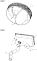
Figure 3 - is the perspective view of the discharge hole and the lid. -
Figure 4 - is the bottom detailed perspective view of the exhaust hood together with the waste collection tank and the discharge hose. -
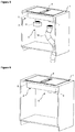
Figure 5 - is the perspective view of the exhaust hood together with the waste collection tank and the discharge hose. -
Figure 6 - is the perspective view of the exhaust hood when the waste collection tank is mounted. - The elements illustrated in the figures are numbered as follows:
- 1.
- Cooktop
- 2.
- Exhaust hood
- 3.
- Fan
- 4.
- Opening
- 5.
- Casing
- 6.
- Discharge hole
- 7.
- Lid
- 8.
- Discharge member
- 9.
- Waste collection tank
- 10.
- Discharge hose
- 11.
- Sealing member
- The exhaust hood (2) is arranged together with a cooktop (1) having at least one heating member thereon, and comprises at least one opening (4) which is provided on the cooktop (1) or adjacent thereto; a fan (3) which is provided under the cooktop (1) and which sucks air from over the cooktop (1) through the opening (4); a casing (5) under the cooktop (1) wherein the fan (3) is disposed; a discharge hole (6) which is provided on the base of the casing (5); a lid (7) which opens/closes the discharge hole (6); and a discharge member (8) which is connected to the discharge hole (6) at one end and which provides the discharge of the waste passing through the discharge hole (6) outside the exhaust hood (2) (
Figure 1 andFigure 2 ). - In the embodiment of the present invention, the cooktop (1) is produced from for example glass or ceramic, and comprises heating members in different numbers, geometries and structures.
- In an embodiment of the present invention, the heating member is a radiant heater or inductor.
- In an embodiment of the present invention, the exhaust hood (2) is almost a part of the cooktop (1) which is arranged almost adjacent to the cooktop (1), or is closed by means of an additional lid. The exhaust hood (2) comprises a fan (3) designed as a suction fan (3). When the exhaust hood (2) is operated, the fan (3) starts to operate and the vapor leaving the cooking vessel placed onto the cooktop (1) is sucked through the opening (4) into the casing (5) with the operation of the fan (3). Here, the vapor and the condensed liquid reaches the discharge hole (6) so as to be transferred out of the exhaust hood (2) via the discharge member (8).
- In the preferred embodiment of the present invention, the discharge member (8) is a discharge hose (10) with one end connected to the discharge hole (6) and the other end to the main drain. In this embodiment, when the exhaust hood (2) is operated, the fan (3) starts to operate and the vapor leaving the cooking vessel placed onto the cooktop (1) is sucked through the opening (4) into the casing (5) with the operation of the fan (3) so as to reach the discharge hole (6) and to be discharged to the main drain by means of the discharge hose (10). Since the exhaust hood (2) is directly connected to the main drain, the need for frequently cleaning is eliminated, thus providing savings in time. Moreover, the risk of any liquid overflowing and causing damage to the device or the environment wherein the device is installed is eliminated (
Figure 4 andFigure 5 ). - In another embodiment of the present invention, the discharge member (8) is a waste collection tank (9) (
Figure 6 ). - In another embodiment of the present invention, the waste collection tank (9) is connected to the main drain by means of the discharge hose (10).
- In an embodiment of the present invention, the lid (7) opening/closing the discharge hole (6) is a spring lid (7) and can open/close depending on the weight of the liquid. Thus, any unpleasant factors such as odor from the main drain are prevented (
Figure 3 ). - In this embodiment of the present invention, a sealing member (11) placed on the wall of the discharge hole (6) is used for ensuring the leakproofing of the discharge hole (6). The sealing member (11) is preferably a rubber gasket.
- By means of the present invention, by connecting the exhaust hood (2) arranged together with the cooktop (1) to the discharge member (8), the need for removing and replacing the waste collection tank (9) is eliminated.
Claims (9)
- An exhaust hood (2), which is arranged together with a cooktop (1) having at least one heating member thereon, comprising at least one opening (4) which is provided on the cooktop (1) or adjacent thereto and a fan (3) which is provided under the cooktop (1) and which sucks air from over the cooktop (1) through the opening (4), characterized by a casing (5) under the cooktop (1) wherein the fan (3) is disposed; a discharge hole (6) which is provided on the base of the casing (5); a lid (7) which opens/closes the discharge hole (6); and a discharge member (8) which is connected to the discharge hole (6) at one end and which provides the discharge of the waste passing through the discharge hole (6) outside the exhaust hood (2).
- An exhaust hood (2) as in Claim 1, characterized by being almost a part of the cooktop (1) and being arranged almost adjacent to the cooktop (1).
- An exhaust hood (2) as in Claim 1, characterized by being closed by an additional lid.
- An exhaust hood (2) as in Claim 1, 2 and 3, characterized by a fan (3) designed as a suction fan (3).
- An exhaust hood (2) as in Claim 1, characterized by the discharge member (8) comprising a discharge hose (10) with one end connected to the discharge hole (6) and the other end to the main drain.
- An exhaust hood (2) as in Claim 1, characterized by the discharge member (8) comprising a waste collection tank (9).
- An exhaust hood (2) as in Claim 6, characterized by the waste collection tank (9) which is connected to the main drain by means of the discharge hose (10).
- An exhaust hood (2) as in Claim 1, characterized by a spring lid (7) which opens/closes the discharge hole (6).
- An exhaust hood (2) as in Claim 1, characterized by a sealing member (11) which is placed on the wall of the discharge hole (6) for ensuring the leakproofing of the discharge hole (6).
Applications Claiming Priority (1)
| Application Number | Priority Date | Filing Date | Title |
|---|---|---|---|
| TR201918932 | 2019-12-02 |
Publications (1)
| Publication Number | Publication Date |
|---|---|
| EP3832212A1 true EP3832212A1 (en) | 2021-06-09 |
Family
ID=73642678
Family Applications (1)
| Application Number | Title | Priority Date | Filing Date |
|---|---|---|---|
| EP20210335.4A Withdrawn EP3832212A1 (en) | 2019-12-02 | 2020-11-27 | An exhaust hood arranged together with the cooktop |
Country Status (1)
| Country | Link |
|---|---|
| EP (1) | EP3832212A1 (en) |
Citations (6)
| Publication number | Priority date | Publication date | Assignee | Title |
|---|---|---|---|---|
| EP0445121A1 (en) | 1988-09-07 | 1991-09-11 | Voss Ernst Fab As | A broiling apparatus, in particular for grilling. |
| WO1999013172A1 (en) | 1997-09-08 | 1999-03-18 | Split Vision Development Ab | A device at a sink |
| US20030111456A1 (en) | 2001-12-14 | 2003-06-19 | Maytag Corporation | Heater cloaking grill grate system for downdraft cooking appliance |
| DE202016003254U1 (en) * | 2016-05-20 | 2016-06-22 | CDS-Design GmbH | off device |
| EP3255348A1 (en) | 2016-06-09 | 2017-12-13 | BSH Hausgeräte GmbH | Cooking hob with extractor fan and power stage adjustment of an energy provider dependent on the operating mode of the extractor fan and method for operating a cooking hob |
| DE102016123418A1 (en) * | 2016-12-05 | 2018-06-07 | Miele & Cie. Kg | suction |
-
2020
- 2020-11-27 EP EP20210335.4A patent/EP3832212A1/en not_active Withdrawn
Patent Citations (6)
| Publication number | Priority date | Publication date | Assignee | Title |
|---|---|---|---|---|
| EP0445121A1 (en) | 1988-09-07 | 1991-09-11 | Voss Ernst Fab As | A broiling apparatus, in particular for grilling. |
| WO1999013172A1 (en) | 1997-09-08 | 1999-03-18 | Split Vision Development Ab | A device at a sink |
| US20030111456A1 (en) | 2001-12-14 | 2003-06-19 | Maytag Corporation | Heater cloaking grill grate system for downdraft cooking appliance |
| DE202016003254U1 (en) * | 2016-05-20 | 2016-06-22 | CDS-Design GmbH | off device |
| EP3255348A1 (en) | 2016-06-09 | 2017-12-13 | BSH Hausgeräte GmbH | Cooking hob with extractor fan and power stage adjustment of an energy provider dependent on the operating mode of the extractor fan and method for operating a cooking hob |
| DE102016123418A1 (en) * | 2016-12-05 | 2018-06-07 | Miele & Cie. Kg | suction |
Similar Documents
| Publication | Publication Date | Title |
|---|---|---|
| US20200094180A1 (en) | Filter unit for a fume extraction device, and combination appliance having a cooktop and a fume extraction device having a filter unit | |
| CN111051779A (en) | Kitchen range | |
| CN104251505B (en) | Family expenses aspirate hood | |
| DE102016123418A1 (en) | suction | |
| EP3916308A1 (en) | Condensate collecting device usable in a household appliance and household appliance comprising such a device | |
| CN105919397B (en) | The anti-overflow electric cooker of air-blowing | |
| US20080203095A1 (en) | Vapor-guiding lid for cookware | |
| CN223667765U (en) | Liquid draining mechanism and cooking equipment using same | |
| EP3382285A1 (en) | Opening system with gas struts and hinges for induction hob with integrated cooker hood | |
| CN211876108U (en) | Self-cleaning automatic cooking cabinet of smoke exhaust ventilator | |
| CN210088953U (en) | Waste oil recovery device | |
| WO2023096605A1 (en) | A cooker with integrated ventilation mechanism | |
| EP3846628B1 (en) | A cooking device comprising a sealing element | |
| CN105890001A (en) | Kitchen ventilator with collection container | |
| EP4331705A1 (en) | Filter element or assembly, fume extraction unit and combination appliance | |
| RU2019143755A (en) | COOKER AND COOKER DRAWER | |
| JP2016065653A (en) | Range food | |
| CN211451057U (en) | Automatic cooking cabinet with deep-cleaning range hood | |
| CN211451065U (en) | Gas treatment equipment convenient to clean and gas treatment pipeline system | |
| EP4379265A1 (en) | Container for collection of flowing substances, drainage auxiliary tool and household appliance | |
| EP4437278A1 (en) | A cooker with integrated ventilation mechanism | |
| CN220601570U (en) | Easy-to-clean electromagnetic oven | |
| RU2854580C2 (en) | Cooking device | |
| CN211451069U (en) | Gas treatment channel structure convenient to clean | |
| CN220379735U (en) | Integrated kitchen range |
Legal Events
| Date | Code | Title | Description |
|---|---|---|---|
| PUAI | Public reference made under article 153(3) epc to a published international application that has entered the european phase |
Free format text: ORIGINAL CODE: 0009012 |
|
| STAA | Information on the status of an ep patent application or granted ep patent |
Free format text: STATUS: REQUEST FOR EXAMINATION WAS MADE |
|
| 17P | Request for examination filed |
Effective date: 20201127 |
|
| AK | Designated contracting states |
Kind code of ref document: A1 Designated state(s): AL AT BE BG CH CY CZ DE DK EE ES FI FR GB GR HR HU IE IS IT LI LT LU LV MC MK MT NL NO PL PT RO RS SE SI SK SM TR |
|
| STAA | Information on the status of an ep patent application or granted ep patent |
Free format text: STATUS: THE APPLICATION IS DEEMED TO BE WITHDRAWN |
|
| 18D | Application deemed to be withdrawn |
Effective date: 20211210 |