EP3832207A1 - Fuel injector assembly - Google Patents
Fuel injector assembly Download PDFInfo
- Publication number
- EP3832207A1 EP3832207A1 EP20212215.6A EP20212215A EP3832207A1 EP 3832207 A1 EP3832207 A1 EP 3832207A1 EP 20212215 A EP20212215 A EP 20212215A EP 3832207 A1 EP3832207 A1 EP 3832207A1
- Authority
- EP
- European Patent Office
- Prior art keywords
- wall
- swirler
- axis
- distal
- passage
- Prior art date
- Legal status (The legal status is an assumption and is not a legal conclusion. Google has not performed a legal analysis and makes no representation as to the accuracy of the status listed.)
- Granted
Links
Images





Classifications
-
- F—MECHANICAL ENGINEERING; LIGHTING; HEATING; WEAPONS; BLASTING
- F23—COMBUSTION APPARATUS; COMBUSTION PROCESSES
- F23R—GENERATING COMBUSTION PRODUCTS OF HIGH PRESSURE OR HIGH VELOCITY, e.g. GAS-TURBINE COMBUSTION CHAMBERS
- F23R3/00—Continuous combustion chambers using liquid or gaseous fuel
- F23R3/02—Continuous combustion chambers using liquid or gaseous fuel characterised by the air-flow or gas-flow configuration
- F23R3/04—Air inlet arrangements
- F23R3/10—Air inlet arrangements for primary air
- F23R3/12—Air inlet arrangements for primary air inducing a vortex
- F23R3/14—Air inlet arrangements for primary air inducing a vortex by using swirl vanes
-
- F—MECHANICAL ENGINEERING; LIGHTING; HEATING; WEAPONS; BLASTING
- F23—COMBUSTION APPARATUS; COMBUSTION PROCESSES
- F23R—GENERATING COMBUSTION PRODUCTS OF HIGH PRESSURE OR HIGH VELOCITY, e.g. GAS-TURBINE COMBUSTION CHAMBERS
- F23R3/00—Continuous combustion chambers using liquid or gaseous fuel
- F23R3/28—Continuous combustion chambers using liquid or gaseous fuel characterised by the fuel supply
- F23R3/283—Attaching or cooling of fuel injecting means including supports for fuel injectors, stems, or lances
-
- F—MECHANICAL ENGINEERING; LIGHTING; HEATING; WEAPONS; BLASTING
- F23—COMBUSTION APPARATUS; COMBUSTION PROCESSES
- F23R—GENERATING COMBUSTION PRODUCTS OF HIGH PRESSURE OR HIGH VELOCITY, e.g. GAS-TURBINE COMBUSTION CHAMBERS
- F23R3/00—Continuous combustion chambers using liquid or gaseous fuel
- F23R3/28—Continuous combustion chambers using liquid or gaseous fuel characterised by the fuel supply
- F23R3/286—Continuous combustion chambers using liquid or gaseous fuel characterised by the fuel supply having fuel-air premixing devices
-
- F—MECHANICAL ENGINEERING; LIGHTING; HEATING; WEAPONS; BLASTING
- F23—COMBUSTION APPARATUS; COMBUSTION PROCESSES
- F23R—GENERATING COMBUSTION PRODUCTS OF HIGH PRESSURE OR HIGH VELOCITY, e.g. GAS-TURBINE COMBUSTION CHAMBERS
- F23R3/00—Continuous combustion chambers using liquid or gaseous fuel
- F23R3/28—Continuous combustion chambers using liquid or gaseous fuel characterised by the fuel supply
- F23R3/30—Continuous combustion chambers using liquid or gaseous fuel characterised by the fuel supply comprising fuel prevapourising devices
-
- F—MECHANICAL ENGINEERING; LIGHTING; HEATING; WEAPONS; BLASTING
- F23—COMBUSTION APPARATUS; COMBUSTION PROCESSES
- F23D—BURNERS
- F23D2900/00—Special features of, or arrangements for burners using fluid fuels or solid fuels suspended in a carrier gas
- F23D2900/11101—Pulverising gas flow impinging on fuel from pre-filming surface, e.g. lip atomizers
Definitions
- This disclosure relates generally to a fuel injector assembly and, more particularly, to a fuel injector assembly with a high shear swirler.
- an assembly for a turbine engine.
- This turbine engine assembly includes a swirler and a fuel nozzle.
- the swirler is configured with an outer wall, an inner wall, an outer passage and an inner passage.
- the outer wall circumscribes the inner wall and extends axially along an axis to a distal outer wall end.
- the inner wall extends axially along the axis to a distal inner wall end that is axially recessed within the swirler from the distal outer wall end.
- the outer passage is formed by and radially between the inner wall and the outer wall.
- the inner passage is formed by and radially within the inner wall.
- the fuel nozzle projects into the inner passage.
- the fuel nozzle is configured with a plurality of orifices axially aligned with the inner wall and arranged circumferentially about the axis.
- a fuel injector assembly with an axis includes a swirler and a fuel nozzle.
- the swirler is configured with an outer wall, an inner wall, an outer passage and an inner passage.
- the outer wall extends axially along the axis to a distal outer wall end.
- the inner wall is radially within the outer wall and extends axially along the axis to a distal inner wall end.
- the distal inner wall end is axially offset from the distal outer wall end along the axis.
- the outer passage is radially between the inner wall and the outer wall.
- the inner passage is radially within the inner wall.
- the fuel nozzle projects into the inner passage.
- the fuel nozzle is configured to direct a plurality of jets of fuel against the inner wall.
- This fuel injector assembly includes a swirler and a fuel nozzle.
- the swirler is configured with an outer wall, an inner wall, an outer passage and an inner passage.
- the outer wall extends circumferentially about the inner wall and extends axially along the axis to a distal outer wall end.
- the inner wall extends axially along the axis to a distal inner wall end.
- the outer passage is radially between the inner wall and the outer wall.
- the inner passage is radially within the inner wall.
- the fuel nozzle projects into the inner passage.
- the distal outer wall end is disposed a first distance along the axis from a tip of the fuel nozzle.
- the distal outer wall end is disposed a second distance along the axis from the distal inner wall end.
- the outer passage has a diameter at the distal outer wall end. A quotient of (the first distance minus the second distance) divided by the diameter is less than one.
- the plurality of orifices may include a first orifice that is configured to direct a jet of fuel to impinge against the inner wall.
- the fuel nozzle may be further configured with a second orifice that is coaxial with the axis.
- the distal outer wall end may be disposed a first distance along the axis from a tip of the fuel nozzle.
- the distal outer wall end may be disposed a second distance along the axis from the distal inner wall end.
- the outer passage may have a diameter at the distal outer wall end. A quotient of (the first distance minus the second distance) divided by the diameter may be less than one.
- the quotient may be less than or equal to 0.8.
- the quotient may be greater than or equal to 0.25.
- the quotient may be between 0.35 and 0.68; e.g., 0.35 ⁇ quotient ⁇ 0.68.
- the distal outer wall end may be disposed a distance along the axis from a tip of the fuel nozzle.
- the outer passage may have a diameter at the distal outer wall end. A quotient of the distance divided by the diameter may be less than one.
- the quotient may be between 0.5 and 0.75; e.g., 0.5 ⁇ quotient ⁇ 0.75.
- the distal outer wall end may be disposed a first distance along the axis from a tip of the fuel nozzle.
- the distal outer wall end may be disposed a second distance along the axis from the distal inner wall end.
- the outer passage may have a diameter at the distal outer wall end. A quotient of the second distance divided by the diameter may be between 0.07 and 0.15; e.g., 0.07 ⁇ quotient ⁇ 0.15.
- the swirler may include a first set of vanes and a second set of vanes.
- the first set of vanes may be arranged with the outer passage.
- the second set of vanes may be arranged with the inner passage.
- the swirler may further include a third set of vanes arranged with the inner passage.
- the third set of vanes may be axially offset from the second set of vanes.
- a nozzle guide plate may be included that mounts the fuel nozzle to the swirler.
- the distal inner wall end may be located axially between the distal outer wall end and a tip of the fuel nozzle along the axis.
- the fuel nozzle may be configured with a plurality of orifices that are axially overlapped by the inner wall and arranged circumferentially about the axis.
- the present disclosure may include any one or more of the individual features disclosed above and/or below alone or in any combination thereof.
- FIG. 1 is a side cutaway illustration of a geared turbine engine 20.
- This turbine engine 20 extends along an axial centerline 22 between an upstream airflow inlet 24 and a downstream airflow exhaust 26.
- the turbine engine 20 includes a fan section 28, a compressor section 29, a combustor section 30 and a turbine section 31.
- the compressor section 29 includes a low pressure compressor (LPC) section 29A and a high pressure compressor (HPC) section 29B.
- the turbine section 31 includes a high pressure turbine (HPT) section 31A and a low pressure turbine (LPT) section 31B.
- the engine sections 28, 29A, 29B, 30, 31A and 31B are arranged sequentially along the centerline 22 within an engine housing 32.
- This housing 32 includes an inner case 34 (e.g., a core case) and an outer case 36 (e.g., a fan case).
- the inner case 34 may house one or more of the engine sections 29A-31B; e.g., an engine core.
- the outer case 36 may house at least the fan section 28.
- Each of the engine sections 28, 29A, 29B, 31A and 31B includes a respective rotor 38-42.
- Each of these rotors 38-42 includes a plurality of rotor blades arranged circumferentially around and connected to one or more respective rotor disks.
- the rotor blades may be formed integral with or mechanically fastened, welded, brazed, adhered and/or otherwise attached to the respective rotor disk(s).
- the fan rotor 38 is connected to a gear train 44, for example, through a fan shaft 46.
- the gear train 44 and the LPC rotor 39 are connected to and driven by the LPT rotor 42 through a low speed shaft 47.
- the HPC rotor 40 is connected to and driven by the HPT rotor 41 through a high speed shaft 48.
- the shafts 46-48 are rotatably supported by a plurality of bearings 50; e.g., rolling element and/or thrust bearings. Each of these bearings 50 is connected to the engine housing 32 by at least one stationary structure such as, for example, an annular support strut.
- the core gas path 52 extends sequentially through the engine sections 29A-31B.
- the air within the core gas path 52 may be referred to as "core air”.
- the bypass gas path 54 extends through a bypass duct, which bypasses the engine core.
- the air within the bypass gas path 54 may be referred to as "bypass air”.
- the core air is compressed by the compressor rotors 39 and 40 and directed into an annular combustion chamber 56 of a combustor 58 in the combustor section 30.
- Fuel is injected into the combustion chamber 56 and mixed with the compressed core air to provide a fuel-air mixture.
- This fuel air mixture is ignited and combustion products thereof flow through and sequentially cause the turbine rotors 41 and 42 to rotate.
- the rotation of the turbine rotors 41 and 42 respectively drive rotation of the compressor rotors 40 and 39 and, thus, compression of the air received from a core airflow inlet.
- the rotation of the turbine rotor 42 also drives rotation of the fan rotor 38, which propels bypass air through and out of the bypass gas path 54.
- the propulsion of the bypass air may account for a majority of thrust generated by the turbine engine 20, e.g., more than seventy-five percent (75%) of engine thrust.
- the turbine engine 20 of the present disclosure is not limited to the foregoing exemplary thrust ratio.
- the combustor section 30 includes a plurality of fuel injector assemblies 60 (one visible in FIG. 2 ) arranged circumferentially about the centerline 22 in an annular array.
- the fuel injector assemblies 60 are mounted to an annular bulkhead 62 of the combustor 58.
- the fuel injector assemblies 60 are configured to direct a mixture of fuel and compressed air into the combustion chamber 56 for combustion.
- Each fuel injector assembly 60 includes a high shear swirler 64 and a fuel injector 66.
- the fuel injector assembly 60 of FIG. 2 also includes a mount 68 configured to couple the fuel injector 66 to the swirler 64.
- the swirler 64 extends circumferentially around an axis 70 (e.g., a centerline of the swirler 64) thereby providing the swirler 64 with a full hoop body.
- the swirler 64 extends axially along the axis 70 between a swirler upstream end 72 and a swirler downstream end 74.
- the swirler 64 of FIG. 3 includes an upstream swirler segment 76, a flanged intermediate swirler segment 77 and a flanged downstream swirler segment 78. These swirler segments 76-78 configure the swirler 64 with a tubular swirler outer wall 80, a tubular swirler inner wall 82 (e.g., a fuel filmer) and a plurality of swirler passages 84 and 86.
- a tubular swirler outer wall 80 e.g., a fuel filmer
- swirler inner wall 82 e.g., a fuel filmer
- the upstream swirler segment 76 extends circumferentially around the axis 70.
- the upstream swirler segment 76 is located at (e.g., on, adjacent or proximate) the swirler upstream end 72.
- the upstream swirler segment 76 of FIG. 3 extends axially along the axis 70 from the swirler upstream end 72 to an annular upstream swirler segment surface 88.
- the upstream swirler segment 76 is configured with an upstream set of vanes 90. These upstream vanes 90 are arranged circumferentially around the axis 70 in an annular array. Each upstream vane 90 is circumferentially separated from each circumferentially adjacent (e.g., neighboring) upstream vane 90 by a respective air gap 92. The gaps 92 collectively form an upstream airflow inlet 94 into the swirler 64 at the swirler upstream end 72; see also FIG. 3 .
- the upstream vanes 90 may be configured such that air entering the swirler 64 through the upstream airflow inlet 94 generally flows in a first circumferential direction 96 (e.g., a clockwise direction) about the axis 70.
- the upstream vanes 90 may be configured such that air entering the swirler 64 through the upstream airflow inlet 94 generally flows in a second circumferential direction 98 (e.g., a counterclockwise direction) about the axis 70.
- a second circumferential direction 98 e.g., a counterclockwise direction
- each gap 92 may extend partially axially into the upstream swirler segment 76 from a castellated surface 100 of the segment 76 at the swirler upstream end 72 to a gap end surface 102.
- each gap 92 may be formed completely axially within the swirler 64 and, for example, its upstream swirler segment 76.
- the intermediate swirler segment 77 includes an annular intermediate swirler segment base 104 (e.g., a radial flange) and the swirler inner wall 82.
- the intermediate swirler segment 77 and each of its components 82 and 104 extends circumferentially around the axis 70.
- the intermediate swirler segment base 104 is abutted axially against the upstream swirler segment 76.
- the intermediate swirler segment base 104 may be coupled (e.g., bonded to) the upstream swirler segment surface 88.
- the intermediate swirler segment base 104 extends axially along the axis 70 from the upstream swirler segment 76 to an annular intermediate swirler segment surface 106.
- the intermediate swirler segment base 104 is configured with an intermediate set of vanes 108. These intermediate vanes 108 are arranged circumferentially around the axis 70 in an annular array. Each intermediate vane 108 is circumferentially separated from each circumferentially adjacent (e.g., neighboring) intermediate vane 108 by a respective gap 110. The gaps 110 collectively form an intermediate airflow inlet 112 into the swirler 64; see also FIG. 3 .
- the intermediate vanes 108 may be configured such that air entering the swirler 64 through the intermediate airflow inlet 112 generally flows in the first circumferential direction 96 (e.g., the clockwise direction) about the axis 70.
- first circumferential direction 96 e.g., the clockwise direction
- the intermediate vanes 108 may be configured such that air entering the swirler 64 through the intermediate airflow inlet 112 generally flows in the second circumferential direction 98 (e.g., the counterclockwise direction) about the axis 70.
- This circumferential direction for the intermediate vanes 108 may be the same as the circumferential direction for the upstream vanes 90. However, in other embodiments, the circumferential direction for the intermediate vanes 108 may be the opposite as the circumferential direction for the upstream vanes 90.
- each gap 110 may extend partially axially into the intermediate swirler segment 77 from a castellated surface 114 of the segment at the to a gap end surface 116.
- each gap may be formed completely axially within the swirler 64 and, for example, its intermediate swirler segment 77.
- the swirler inner wall 82 projects out from the intermediate swirler segment base 104 and extends axially (in a downstream direction along the axis 70) to an annular distal inner wall end 118. As the swirler inner wall 82 extends towards the distal inner wall end 118, the swirler inner wall 82 may (e.g., smoothly and/or continuously) radially taper inwards towards the axis 70. The swirler inner wall 82 may thereby have a tubular conical geometry with tubular conical inner and outer wall surfaces 120 and 122. The swirler inner wall 82 and its distal end 118 are each disposed radially with and axially overlapped by the swirler outer wall 80.
- the downstream swirler segment 78 includes an annular downstream swirler segment base 124 (e.g., a radial flange) and the swirler outer wall 80.
- the downstream swirler segment 78 and each of its components 80 and 124 extends circumferentially around the axis 70.
- the downstream swirler segment base 124 is abutted axially against the intermediate swirler segment 77.
- the downstream swirler segment base 124 may be coupled (e.g., bonded to) the intermediate swirler segment surface 106.
- the downstream swirler segment base 124 extends axially along the axis 70 from the intermediate swirler segment 77 to an annular downstream swirler segment surface 126.
- the downstream swirler segment base 124 is configured with a downstream set of vanes 128. These downstream vanes 128 are arranged circumferentially around the axis 70 in an annular array. Each downstream vane 128 is circumferentially separated from each circumferentially adjacent (e.g., neighboring) downstream vane 128 by a respective gap 130. The gaps 130 collectively form a downstream airflow inlet 132 into the swirler 64; see also FIG. 3 .
- the downstream vanes 128 may be configured such that air entering the swirler 64 through the downstream airflow inlet 132 generally flow in the first circumferential direction 96 (e.g., the clockwise direction) about the axis 70.
- first circumferential direction 96 e.g., the clockwise direction
- the downstream vanes 128 may be configured such that air entering the swirler 64 through the downstream airflow inlet 132 generally flows in the second circumferential direction 98 (e.g., the counterclockwise direction) about the axis 70.
- This circumferential direction for the downstream vanes 128 may be the same as the circumferential direction for the upstream vanes 90 and/or the intermediate vanes 108.
- the circumferential direction for the downstream vanes 128 may be the opposite as the circumferential direction for the upstream vanes 90 and/or the intermediate vanes 108.
- each gap 130 may extend partially axially into the downstream swirler segment 78 from a castellated surface 134 of the segment at the to a gap end surface 136.
- each gap 130 may be formed completely axially within the swirler 64 and, for example, its downstream swirler segment 78.
- the swirler outer wall 80 projects out from the downstream swirler segment base 124 and extends axially (in the downstream direction along the axis 70) to an annular distal outer wall end 138. As the swirler outer wall 80 extends towards the distal outer wall end 138, the swirler outer wall 80 may (e.g., smoothly and/or continuously) radially taper inwards towards the axis 70.
- the swirler outer wall 80 may thereby have a generally tubular conical geometry with a tubular conical inner wall surface 140.
- the swirler outer wall 80 axially overlaps and circumscribes the swirler outer wall 80.
- the swirler 64 is configured such that the distal inner wall end 118 and the distal outer wall end 138 are axially offset from one another along the axis 70.
- the distal inner wall end 118 of FIG. 3 for example, is axially recessed into the swirler 64 from the distal outer wall end 138. More particularly, the distal inner wall end 118 is disposed an axial distance (d) upstream of the distal outer wall end 138.
- the distal outer wall end 138 may thereby define a downstream most surface of the swirler 64; e.g., a dump plane of the swirler 64.
- the inner passage 84 of FIG. 3 is an inner bore of the swirler 64. This inner passage 84 is formed radially within and by each of the swirler segments 76 and 77. The inner passage 84 is fluidly coupled with the upstream airflow inlet 94 and the intermediate airflow inlet 112. The inner passage 84 of FIG. 3 extends from the airflow inlets 94 and 112 to an inner nozzle outlet 142. This inner nozzle outlet 142 is defined by and radially within the swirler inner wall 82 at the distal inner wall end 118.
- the outer passage 86 of FIG. 3 is an annular passage formed by the swirler segments 77 and 78. This outer passage 86 is formed radially between the swirler inner wall 82 and the swirler outer wall 80. The outer passage 86 is fluidly coupled with the downstream airflow inlet 132. The outer passage 86 of FIG. 3 extends from the downstream airflow inlet 132 to an outer nozzle outlet 144. This outer nozzle outlet 144 is defined by and radially between the swirler inner and outer walls 82 and 80 at their distal ends 118 and 138.
- the outer passage 86 and its nozzle outlet 144 are configured with an inner diameter (D sw-ex ) at the distal outer wall end 138.
- This diameter (D sw-ex ) is measured from, for example, the inner wall surface 140 of the swirler outer wall 80 on a corner between that surface 140 and an annular distal outer wall end surface 146.
- the swirler 64 is mated with the bulkhead 62.
- the swirler inner and outer walls 82 and 80 project axially into or through a respective aperture 148 in the bulkhead 62.
- the swirler 64 is mounted to the bulkhead 62.
- the downstream swirler segment 78 may be bonded (e.g., brazed or welded) and/or otherwise connected to the bulkhead 62 and, for example, a shell 150 of the bulkhead 62.
- the fuel injector 66 includes a fuel injector stem 152 and a fuel injector nozzle 154.
- the fuel injector stem 152 is configured to support and route fuel to the fuel injector nozzle 154.
- the fuel injector nozzle 154 is cantilevered from the fuel injector stem 152, and projects along the axis 70 partially into the inner bore of the swirler 64. A tip 156 of the fuel injector nozzle 154 is thereby disposed within the inner passage 84.
- the fuel injector nozzle 154 includes a plurality of nozzle orifices 158 arranged circumferentially about the axis 70 in an annular array; see also FIG. 8 .
- These nozzle orifices 158 may be axially aligned with (e.g., axially overlapped by) the swirler inner wall 82 and its inner wall surface 120.
- One or more or each of these nozzle orifices 158 is configured to direct a jet of fuel to impinge against the swirler inner wall 82 and its inner wall surface 120.
- the fuel injector nozzle 154 may also include a central nozzle orifice 160; see also FIG. 8 .
- This central nozzle orifice 160 may be coaxial with the axis 70 and thereby centrally located between the nozzle orifices 158.
- the central nozzle orifice 160 is configured to direct a jet of fuel along the axis 70, through the inner nozzle outlet 142, and into the combustion chamber 56.
- a quantity of fuel provided by this central nozzle orifice 160 may be less than a collective quantity of fuel provided by the nozzle orifices 158; however, the present disclosure is not limited to such a relationship.
- the mount 68 is configured to couple the fuel injector nozzle 154 to the swirler 64.
- the mount 68 of FIG. 7 for example, includes a mount base 162 and a nozzle guide plate 164.
- the mount base 162 is connected (e.g., bonded) to the upstream swirler segment 76 and, for example, to its castellated surface 100.
- the mount base 162 is configured to capture the nozzle guide plate 164 in such a fashion that the nozzle guide plate 164 may float, to a limited degree, relative to the swirler 64.
- the nozzle guide plate 164 in turn is mated with the fuel injector nozzle 154.
- the fuel injector nozzle 154 for example, projects through a bore in the nozzle guide plate 164.
- the bore is sized such that the fuel injector nozzle 154 may slide axially along the axis 70 relative to the nozzle guide plate 164.
- the mount 68 thereby may (e.g., loosely) couple and locate the fuel injector nozzle 154 to the swirler while enabling for slight shifts due to differential thermal expansion as well as vibrations.
- the nozzle orifices 158 direct the jets of fuel to impinge against the swirler inner wall 82.
- the swirling air introduced into the inner passage 84 form the airflow inlets 94 and 112 (see FIG. 3 ) may cause the fuel from the jets to form a thin film of fuel on the inner wall surface 120.
- This film of fuel travels along the inner wall surface 120 towards the inner nozzle outlet 142.
- the film of fuel separates from the swirler inner wall 82 and is acted upon by swirling air exiting both the inner nozzle outlet 142 and the outer nozzle outlet 144.
- the air may exit the nozzle outlets 142 and 144 at different speeds and thereby subject the separated fuel to a shear force. This shear force may cause the separated fuel to break up and atomize for combustion within the combustion chamber 56.
- Atomization quality may depend upon a thickness of the film of fuel as well as a velocity and swirl of the air from the inner and the outer passages 84 and 86.
- the thickness of the film of fuel may depend upon an amount of fuel injected by the nozzle orifices 158 onto the swirler inner wall 82 and a length of travel along the swirler inner wall 82. Therefore, in general, decreasing the length of travel of the film of fuel along the swirler inner wall 82 may result in a thinner film thickness.
- the distal inner wall end 118 is positioned forward of the distal outer wall end 138 as described above.
- the fuel injector assembly 60 of the present disclosure may be operable to facilitate improved fuel and air mixing and/or a reduction in combustion dynamics.
- the tip 156 of the fuel injector nozzle 154 is disposed an axial distance (D) along the axis 70 from the distal outer wall end 138.
- D axial distance
- the fuel injector assembly 60 may be configured such that the equation (D - d) / D sw-ex is less than or equal to one (e.g., less than 0.80) and/or greater than or equal to 0.25 (e.g., greater than 0.30).
- the fuel injector assembly 60 for example, may be configured such that the equation (D - d) / D sw-ex is between 0.35 and 0.68.
- the fuel injector assembly 60 may be configured such that the equation D / D sw-ex is less than or equal to one and/or greater than or equal to 0.40.
- the fuel injector assembly 60 for example, may be configured such that the equation D / D sw-ex is between 0.50 and 0.75.
- the fuel injector assembly 60 may be configured such that the equation d / D sw-ex is less than or equal to 0.20 and/or greater than or equal to 0.05.
- the fuel injector assembly 60 for example, may be configured such that the equation d / D sw-ex is between 0.07 and 0.15.
- each segment 76-78 may be discretely formed and subsequently connected (e.g., bonded and/or mechanically fastened) to the other segment(s).
- the swirler 64 may be configured such that any two or all of the segments 76-78 are formed integrally together as a unitary, monolithic body via, for example, casting and/or additive manufacturing.
- the swirler 64 may be configured with two airflow inlets.
- the swirler 64 for example, may be configured without the upstream swirler segment 76.
- the swirler 64 may be configured with more than three airflow inlets.
- the fuel injector assembly 60 may be included in various turbine engines other than the one described above as well as in other types of fuel powered equipment.
- the fuel injector assembly 60 may be included in a geared turbine engine where a gear train connects one or more shafts to one or more rotors in a fan section, a compressor section and/or any other engine section.
- the fuel injector assembly 60 may be included in a turbine engine configured without a gear train.
- the fuel injector assembly 60 may be included in a geared or non-geared turbine engine configured with a single spool, with two spools (e.g., see FIG. 1 ), or with more than two spools.
- the turbine engine may be configured as a turbofan engine, a turbojet engine, a propfan engine, a pusher fan engine or any other type of turbine engine. The present disclosure therefore is not limited to any particular types or configurations of turbine engines or equipment.
Landscapes
- Engineering & Computer Science (AREA)
- Chemical & Material Sciences (AREA)
- Combustion & Propulsion (AREA)
- Mechanical Engineering (AREA)
- General Engineering & Computer Science (AREA)
- Fuel-Injection Apparatus (AREA)
- Turbine Rotor Nozzle Sealing (AREA)
Abstract
Description
- This disclosure relates generally to a fuel injector assembly and, more particularly, to a fuel injector assembly with a high shear swirler.
- Various types and configurations of fuel injector assemblies are known in the art. Some of these known fuel injector assemblies include a high shear swirler mated with a fuel injector nozzle. While these known fuel injector assemblies have various advantages, there is still room in the art for improvement. In particular, there is still room in the art for fuel injector assemblies capable of improving fuel-air mixing, reducing combustor dynamics and/or reducing undesirable combustor tones.
- According to an aspect of the present disclosure, an assembly is provided for a turbine engine. This turbine engine assembly includes a swirler and a fuel nozzle. The swirler is configured with an outer wall, an inner wall, an outer passage and an inner passage. The outer wall circumscribes the inner wall and extends axially along an axis to a distal outer wall end. The inner wall extends axially along the axis to a distal inner wall end that is axially recessed within the swirler from the distal outer wall end. The outer passage is formed by and radially between the inner wall and the outer wall. The inner passage is formed by and radially within the inner wall. The fuel nozzle projects into the inner passage. The fuel nozzle is configured with a plurality of orifices axially aligned with the inner wall and arranged circumferentially about the axis.
- According to another aspect of the present disclosure, a fuel injector assembly with an axis is provided. This fuel injector assembly includes a swirler and a fuel nozzle. The swirler is configured with an outer wall, an inner wall, an outer passage and an inner passage. The outer wall extends axially along the axis to a distal outer wall end. The inner wall is radially within the outer wall and extends axially along the axis to a distal inner wall end. The distal inner wall end is axially offset from the distal outer wall end along the axis. The outer passage is radially between the inner wall and the outer wall. The inner passage is radially within the inner wall. The fuel nozzle projects into the inner passage. The fuel nozzle is configured to direct a plurality of jets of fuel against the inner wall.
- According to still another aspect of the present disclosure, another fuel injector assembly with an axis is provided. This fuel injector assembly includes a swirler and a fuel nozzle. The swirler is configured with an outer wall, an inner wall, an outer passage and an inner passage. The outer wall extends circumferentially about the inner wall and extends axially along the axis to a distal outer wall end. The inner wall extends axially along the axis to a distal inner wall end. The outer passage is radially between the inner wall and the outer wall. The inner passage is radially within the inner wall. The fuel nozzle projects into the inner passage. The distal outer wall end is disposed a first distance along the axis from a tip of the fuel nozzle. The distal outer wall end is disposed a second distance along the axis from the distal inner wall end. The outer passage has a diameter at the distal outer wall end. A quotient of (the first distance minus the second distance) divided by the diameter is less than one.
- The following optional features apply to any of the above aspects.
- The plurality of orifices may include a first orifice that is configured to direct a jet of fuel to impinge against the inner wall.
- The fuel nozzle may be further configured with a second orifice that is coaxial with the axis.
- The distal outer wall end may be disposed a first distance along the axis from a tip of the fuel nozzle. The distal outer wall end may be disposed a second distance along the axis from the distal inner wall end. The outer passage may have a diameter at the distal outer wall end. A quotient of (the first distance minus the second distance) divided by the diameter may be less than one.
- The quotient may be less than or equal to 0.8.
- The quotient may be greater than or equal to 0.25.
- The quotient may be between 0.35 and 0.68; e.g., 0.35 ≤ quotient ≤ 0.68.
- The distal outer wall end may be disposed a distance along the axis from a tip of the fuel nozzle. The outer passage may have a diameter at the distal outer wall end. A quotient of the distance divided by the diameter may be less than one.
- The quotient may be between 0.5 and 0.75; e.g., 0.5 ≤ quotient ≤ 0.75.
- The distal outer wall end may be disposed a first distance along the axis from a tip of the fuel nozzle. The distal outer wall end may be disposed a second distance along the axis from the distal inner wall end. The outer passage may have a diameter at the distal outer wall end. A quotient of the second distance divided by the diameter may be between 0.07 and 0.15; e.g., 0.07 ≤ quotient ≤ 0.15.
- The swirler may include a first set of vanes and a second set of vanes. The first set of vanes may be arranged with the outer passage. The second set of vanes may be arranged with the inner passage.
- The swirler may further include a third set of vanes arranged with the inner passage. The third set of vanes may be axially offset from the second set of vanes.
- A nozzle guide plate may be included that mounts the fuel nozzle to the swirler.
- The distal inner wall end may be located axially between the distal outer wall end and a tip of the fuel nozzle along the axis.
- The fuel nozzle may be configured with a plurality of orifices that are axially overlapped by the inner wall and arranged circumferentially about the axis.
- The present disclosure may include any one or more of the individual features disclosed above and/or below alone or in any combination thereof.
- The foregoing features and the operation of the invention will become more apparent in light of the following description and the accompanying drawings.
-
-
FIG. 1 is a side cutaway illustration of a geared turbine engine. -
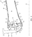
FIG. 2 is a partial side sectional illustration of a combustor section. -
FIG. 3 is a side sectional illustration of a swirler. -
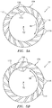
FIG. 4A is an end view illustration of an upstream swirler segment of the swirler with vanes arranged in a first circumferential direction. -
FIG. 4B is an end view illustration of the upstream swirler segment with the vanes arranged in a second circumferential direction. -
FIG. 5A is an end view illustration of an intermediate swirler segment of the swirler with vanes arranged in the first circumferential direction. -
FIG. 5B is an end view illustration of the intermediate swirler segment with the vanes arranged in the second circumferential direction. -
FIG. 6A is an end view illustration of a downstream swirler segment of the swirler with vanes arranged in the first circumferential direction. -
FIG. 6B is an end view illustration of the downstream swirler segment with the vanes arranged in the second circumferential direction. -
FIG. 7 is a partial side sectional illustration of the swirler mated with a fuel nozzle and a combustor bulkhead. -
FIG. 8 is an end view illustration of a tip of the fuel nozzle. -
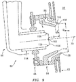
FIG. 9 is another partial side sectional illustration of the swirler mated with the fuel nozzle and the combustor bulkhead. -
FIG. 1 is a side cutaway illustration of a gearedturbine engine 20. Thisturbine engine 20 extends along anaxial centerline 22 between anupstream airflow inlet 24 and adownstream airflow exhaust 26. Theturbine engine 20 includes afan section 28, acompressor section 29, acombustor section 30 and aturbine section 31. Thecompressor section 29 includes a low pressure compressor (LPC)section 29A and a high pressure compressor (HPC)section 29B. Theturbine section 31 includes a high pressure turbine (HPT)section 31A and a low pressure turbine (LPT)section 31B. - The
engine sections centerline 22 within anengine housing 32. Thishousing 32 includes an inner case 34 (e.g., a core case) and an outer case 36 (e.g., a fan case). Theinner case 34 may house one or more of theengine sections 29A-31B; e.g., an engine core. Theouter case 36 may house at least thefan section 28. - Each of the
engine sections - The
fan rotor 38 is connected to agear train 44, for example, through afan shaft 46. Thegear train 44 and theLPC rotor 39 are connected to and driven by theLPT rotor 42 through alow speed shaft 47. TheHPC rotor 40 is connected to and driven by theHPT rotor 41 through ahigh speed shaft 48. The shafts 46-48 are rotatably supported by a plurality ofbearings 50; e.g., rolling element and/or thrust bearings. Each of thesebearings 50 is connected to theengine housing 32 by at least one stationary structure such as, for example, an annular support strut. - During operation, air enters the
turbine engine 20 through theairflow inlet 24. This air is directed through thefan section 28 and into acore gas path 52 and abypass gas path 54. Thecore gas path 52 extends sequentially through theengine sections 29A-31B. The air within thecore gas path 52 may be referred to as "core air". Thebypass gas path 54 extends through a bypass duct, which bypasses the engine core. The air within thebypass gas path 54 may be referred to as "bypass air". - The core air is compressed by the
compressor rotors annular combustion chamber 56 of acombustor 58 in thecombustor section 30. Fuel is injected into thecombustion chamber 56 and mixed with the compressed core air to provide a fuel-air mixture. This fuel air mixture is ignited and combustion products thereof flow through and sequentially cause theturbine rotors turbine rotors compressor rotors turbine rotor 42 also drives rotation of thefan rotor 38, which propels bypass air through and out of thebypass gas path 54. The propulsion of the bypass air may account for a majority of thrust generated by theturbine engine 20, e.g., more than seventy-five percent (75%) of engine thrust. Theturbine engine 20 of the present disclosure, however, is not limited to the foregoing exemplary thrust ratio. - Referring to
FIG. 2 , thecombustor section 30 includes a plurality of fuel injector assemblies 60 (one visible inFIG. 2 ) arranged circumferentially about thecenterline 22 in an annular array. Thefuel injector assemblies 60 are mounted to anannular bulkhead 62 of thecombustor 58. Thefuel injector assemblies 60 are configured to direct a mixture of fuel and compressed air into thecombustion chamber 56 for combustion. - Each
fuel injector assembly 60 includes ahigh shear swirler 64 and afuel injector 66. Thefuel injector assembly 60 ofFIG. 2 also includes amount 68 configured to couple thefuel injector 66 to theswirler 64. - Referring to
FIG. 3 , theswirler 64 extends circumferentially around an axis 70 (e.g., a centerline of the swirler 64) thereby providing theswirler 64 with a full hoop body. Theswirler 64 extends axially along theaxis 70 between a swirlerupstream end 72 and a swirlerdownstream end 74. - The
swirler 64 ofFIG. 3 includes anupstream swirler segment 76, a flangedintermediate swirler segment 77 and a flangeddownstream swirler segment 78. These swirler segments 76-78 configure theswirler 64 with a tubular swirlerouter wall 80, a tubular swirler inner wall 82 (e.g., a fuel filmer) and a plurality ofswirler passages - The
upstream swirler segment 76 extends circumferentially around theaxis 70. Theupstream swirler segment 76 is located at (e.g., on, adjacent or proximate) the swirlerupstream end 72. Theupstream swirler segment 76 ofFIG. 3 , for example, extends axially along theaxis 70 from the swirlerupstream end 72 to an annular upstreamswirler segment surface 88. - Referring to
FIG. 4A , theupstream swirler segment 76 is configured with an upstream set ofvanes 90. Theseupstream vanes 90 are arranged circumferentially around theaxis 70 in an annular array. Eachupstream vane 90 is circumferentially separated from each circumferentially adjacent (e.g., neighboring)upstream vane 90 by arespective air gap 92. Thegaps 92 collectively form anupstream airflow inlet 94 into theswirler 64 at the swirlerupstream end 72; see alsoFIG. 3 . Theupstream vanes 90 may be configured such that air entering theswirler 64 through theupstream airflow inlet 94 generally flows in a first circumferential direction 96 (e.g., a clockwise direction) about theaxis 70. Alternatively, referring toFIG. 4B , theupstream vanes 90 may be configured such that air entering theswirler 64 through theupstream airflow inlet 94 generally flows in a second circumferential direction 98 (e.g., a counterclockwise direction) about theaxis 70. - In the specific embodiment of
FIG. 3 , theupstream vanes 90 are arranged at the swirlerupstream end 72. With this arrangement, eachgap 92 may extend partially axially into theupstream swirler segment 76 from acastellated surface 100 of thesegment 76 at the swirlerupstream end 72 to agap end surface 102. Of course, in other embodiments, eachgap 92 may be formed completely axially within theswirler 64 and, for example, itsupstream swirler segment 76. - The
intermediate swirler segment 77 includes an annular intermediate swirler segment base 104 (e.g., a radial flange) and the swirlerinner wall 82. Theintermediate swirler segment 77 and each of itscomponents axis 70. - The intermediate
swirler segment base 104 is abutted axially against theupstream swirler segment 76. The intermediateswirler segment base 104, for example, may be coupled (e.g., bonded to) the upstreamswirler segment surface 88. The intermediateswirler segment base 104 extends axially along theaxis 70 from theupstream swirler segment 76 to an annular intermediateswirler segment surface 106. - Referring to
FIG. 5A , the intermediateswirler segment base 104 is configured with an intermediate set ofvanes 108. Theseintermediate vanes 108 are arranged circumferentially around theaxis 70 in an annular array. Eachintermediate vane 108 is circumferentially separated from each circumferentially adjacent (e.g., neighboring)intermediate vane 108 by arespective gap 110. Thegaps 110 collectively form anintermediate airflow inlet 112 into theswirler 64; see alsoFIG. 3 . Theintermediate vanes 108 may be configured such that air entering theswirler 64 through theintermediate airflow inlet 112 generally flows in the first circumferential direction 96 (e.g., the clockwise direction) about theaxis 70. Alternatively, referring toFIG. 5B , theintermediate vanes 108 may be configured such that air entering theswirler 64 through theintermediate airflow inlet 112 generally flows in the second circumferential direction 98 (e.g., the counterclockwise direction) about theaxis 70. This circumferential direction for theintermediate vanes 108 may be the same as the circumferential direction for theupstream vanes 90. However, in other embodiments, the circumferential direction for theintermediate vanes 108 may be the opposite as the circumferential direction for theupstream vanes 90. - In the specific embodiment of
FIG. 3 , theintermediate vanes 108 are arranged at a joint between theswirler segments gap 110 may extend partially axially into theintermediate swirler segment 77 from acastellated surface 114 of the segment at the to agap end surface 116. Of course, in other embodiments, each gap may be formed completely axially within theswirler 64 and, for example, itsintermediate swirler segment 77. - The swirler
inner wall 82 projects out from the intermediateswirler segment base 104 and extends axially (in a downstream direction along the axis 70) to an annular distalinner wall end 118. As the swirlerinner wall 82 extends towards the distalinner wall end 118, the swirlerinner wall 82 may (e.g., smoothly and/or continuously) radially taper inwards towards theaxis 70. The swirlerinner wall 82 may thereby have a tubular conical geometry with tubular conical inner and outer wall surfaces 120 and 122. The swirlerinner wall 82 and itsdistal end 118 are each disposed radially with and axially overlapped by the swirlerouter wall 80. - The
downstream swirler segment 78 includes an annular downstream swirler segment base 124 (e.g., a radial flange) and the swirlerouter wall 80. Thedownstream swirler segment 78 and each of itscomponents axis 70. - The downstream
swirler segment base 124 is abutted axially against theintermediate swirler segment 77. The downstreamswirler segment base 124, for example, may be coupled (e.g., bonded to) the intermediateswirler segment surface 106. The downstreamswirler segment base 124 extends axially along theaxis 70 from theintermediate swirler segment 77 to an annular downstreamswirler segment surface 126. - Referring to
FIG. 6A , the downstreamswirler segment base 124 is configured with a downstream set ofvanes 128. Thesedownstream vanes 128 are arranged circumferentially around theaxis 70 in an annular array. Eachdownstream vane 128 is circumferentially separated from each circumferentially adjacent (e.g., neighboring)downstream vane 128 by arespective gap 130. Thegaps 130 collectively form adownstream airflow inlet 132 into theswirler 64; see alsoFIG. 3 . Thedownstream vanes 128 may be configured such that air entering theswirler 64 through thedownstream airflow inlet 132 generally flow in the first circumferential direction 96 (e.g., the clockwise direction) about theaxis 70. Alternatively, referring toFIG. 6B , thedownstream vanes 128 may be configured such that air entering theswirler 64 through thedownstream airflow inlet 132 generally flows in the second circumferential direction 98 (e.g., the counterclockwise direction) about theaxis 70. This circumferential direction for thedownstream vanes 128 may be the same as the circumferential direction for theupstream vanes 90 and/or theintermediate vanes 108. However, in other embodiments, the circumferential direction for thedownstream vanes 128 may be the opposite as the circumferential direction for theupstream vanes 90 and/or theintermediate vanes 108. - In the specific embodiment of
FIG. 3 , thedownstream vanes 128 are arranged at a joint between theswirler segments gap 130 may extend partially axially into thedownstream swirler segment 78 from acastellated surface 134 of the segment at the to agap end surface 136. Of course, in other embodiments, eachgap 130 may be formed completely axially within theswirler 64 and, for example, itsdownstream swirler segment 78. - The swirler
outer wall 80 projects out from the downstreamswirler segment base 124 and extends axially (in the downstream direction along the axis 70) to an annular distalouter wall end 138. As the swirlerouter wall 80 extends towards the distalouter wall end 138, the swirlerouter wall 80 may (e.g., smoothly and/or continuously) radially taper inwards towards theaxis 70. The swirlerouter wall 80 may thereby have a generally tubular conical geometry with a tubular conicalinner wall surface 140. The swirlerouter wall 80 axially overlaps and circumscribes the swirlerouter wall 80. - The
swirler 64 is configured such that the distalinner wall end 118 and the distalouter wall end 138 are axially offset from one another along theaxis 70. The distalinner wall end 118 ofFIG. 3 , for example, is axially recessed into theswirler 64 from the distalouter wall end 138. More particularly, the distalinner wall end 118 is disposed an axial distance (d) upstream of the distalouter wall end 138. The distalouter wall end 138 may thereby define a downstream most surface of theswirler 64; e.g., a dump plane of theswirler 64. - The
inner passage 84 ofFIG. 3 is an inner bore of theswirler 64. Thisinner passage 84 is formed radially within and by each of theswirler segments inner passage 84 is fluidly coupled with theupstream airflow inlet 94 and theintermediate airflow inlet 112. Theinner passage 84 ofFIG. 3 extends from theairflow inlets inner nozzle outlet 142. Thisinner nozzle outlet 142 is defined by and radially within the swirlerinner wall 82 at the distalinner wall end 118. - The
outer passage 86 ofFIG. 3 is an annular passage formed by theswirler segments outer passage 86 is formed radially between the swirlerinner wall 82 and the swirlerouter wall 80. Theouter passage 86 is fluidly coupled with thedownstream airflow inlet 132. Theouter passage 86 ofFIG. 3 extends from thedownstream airflow inlet 132 to anouter nozzle outlet 144. Thisouter nozzle outlet 144 is defined by and radially between the swirler inner andouter walls distal ends - The
outer passage 86 and itsnozzle outlet 144 are configured with an inner diameter (Dsw-ex) at the distalouter wall end 138. This diameter (Dsw-ex) is measured from, for example, theinner wall surface 140 of the swirlerouter wall 80 on a corner between thatsurface 140 and an annular distal outer wall end surface 146. - Referring to
FIG. 2 , theswirler 64 is mated with thebulkhead 62. In particular, the swirler inner andouter walls respective aperture 148 in thebulkhead 62. Theswirler 64 is mounted to thebulkhead 62. Thedownstream swirler segment 78, for example, may be bonded (e.g., brazed or welded) and/or otherwise connected to thebulkhead 62 and, for example, ashell 150 of thebulkhead 62. - The
fuel injector 66 includes afuel injector stem 152 and afuel injector nozzle 154. The fuel injector stem 152 is configured to support and route fuel to thefuel injector nozzle 154. Thefuel injector nozzle 154 is cantilevered from thefuel injector stem 152, and projects along theaxis 70 partially into the inner bore of theswirler 64. Atip 156 of thefuel injector nozzle 154 is thereby disposed within theinner passage 84. - Referring to
FIG. 7 , thefuel injector nozzle 154 includes a plurality ofnozzle orifices 158 arranged circumferentially about theaxis 70 in an annular array; see alsoFIG. 8 . Thesenozzle orifices 158 may be axially aligned with (e.g., axially overlapped by) the swirlerinner wall 82 and itsinner wall surface 120. One or more or each of thesenozzle orifices 158 is configured to direct a jet of fuel to impinge against the swirlerinner wall 82 and itsinner wall surface 120. - The
fuel injector nozzle 154 may also include acentral nozzle orifice 160; see alsoFIG. 8 . Thiscentral nozzle orifice 160 may be coaxial with theaxis 70 and thereby centrally located between thenozzle orifices 158. Thecentral nozzle orifice 160 is configured to direct a jet of fuel along theaxis 70, through theinner nozzle outlet 142, and into thecombustion chamber 56. A quantity of fuel provided by thiscentral nozzle orifice 160 may be less than a collective quantity of fuel provided by thenozzle orifices 158; however, the present disclosure is not limited to such a relationship. - The
mount 68 is configured to couple thefuel injector nozzle 154 to theswirler 64. Themount 68 ofFIG. 7 , for example, includes amount base 162 and anozzle guide plate 164. Themount base 162 is connected (e.g., bonded) to theupstream swirler segment 76 and, for example, to itscastellated surface 100. Themount base 162 is configured to capture thenozzle guide plate 164 in such a fashion that thenozzle guide plate 164 may float, to a limited degree, relative to theswirler 64. Thenozzle guide plate 164 in turn is mated with thefuel injector nozzle 154. Thefuel injector nozzle 154, for example, projects through a bore in thenozzle guide plate 164. The bore is sized such that thefuel injector nozzle 154 may slide axially along theaxis 70 relative to thenozzle guide plate 164. Themount 68 thereby may (e.g., loosely) couple and locate thefuel injector nozzle 154 to the swirler while enabling for slight shifts due to differential thermal expansion as well as vibrations. - During operation of the
fuel injector assembly 60 ofFIG. 7 , thenozzle orifices 158 direct the jets of fuel to impinge against the swirlerinner wall 82. Upon hitting theinner wall surface 120, the swirling air introduced into theinner passage 84 form theairflow inlets 94 and 112 (seeFIG. 3 ) may cause the fuel from the jets to form a thin film of fuel on theinner wall surface 120. This film of fuel travels along theinner wall surface 120 towards theinner nozzle outlet 142. At theinner nozzle outlet 142, the film of fuel separates from the swirlerinner wall 82 and is acted upon by swirling air exiting both theinner nozzle outlet 142 and theouter nozzle outlet 144. The air may exit thenozzle outlets combustion chamber 56. - Atomization quality may depend upon a thickness of the film of fuel as well as a velocity and swirl of the air from the inner and the
outer passages nozzle orifices 158 onto the swirlerinner wall 82 and a length of travel along the swirlerinner wall 82. Therefore, in general, decreasing the length of travel of the film of fuel along the swirlerinner wall 82 may result in a thinner film thickness. Thus, the distalinner wall end 118 is positioned forward of the distalouter wall end 138 as described above. By providing a thinner film thickness, thefuel injector assembly 60 of the present disclosure may be operable to facilitate improved fuel and air mixing and/or a reduction in combustion dynamics. - Referring to
FIG. 9 , thetip 156 of thefuel injector nozzle 154 is disposed an axial distance (D) along theaxis 70 from the distalouter wall end 138. By minimizing the equation (D - d) / Dsw-ex, by decreasing the equation D / Dsw-exand/or by increasing the equation d / Dsw-ex , it has been found that combustion tones within thecombustion chamber 56 may be reduced. For example, thefuel injector assembly 60 may be configured such that the equation (D - d) / Dsw-ex is less than or equal to one (e.g., less than 0.80) and/or greater than or equal to 0.25 (e.g., greater than 0.30). Thefuel injector assembly 60, for example, may be configured such that the equation (D - d) / Dsw-ex is between 0.35 and 0.68. - The
fuel injector assembly 60 may be configured such that the equation D / Dsw-ex is less than or equal to one and/or greater than or equal to 0.40. Thefuel injector assembly 60, for example, may be configured such that the equation D / Dsw-exis between 0.50 and 0.75. - The
fuel injector assembly 60 may be configured such that the equation d / Dsw-ex is less than or equal to 0.20 and/or greater than or equal to 0.05. Thefuel injector assembly 60, for example, may be configured such that the equation d / Dsw-ex is between 0.07 and 0.15. - The
swirler 64 is described above with a multi-segment body, where each segment 76-78 may be discretely formed and subsequently connected (e.g., bonded and/or mechanically fastened) to the other segment(s). However, in other embodiments, theswirler 64 may be configured such that any two or all of the segments 76-78 are formed integrally together as a unitary, monolithic body via, for example, casting and/or additive manufacturing. - In some embodiments, the
swirler 64 may be configured with two airflow inlets. Theswirler 64, for example, may be configured without theupstream swirler segment 76. In still other embodiments, theswirler 64 may be configured with more than three airflow inlets. - The
fuel injector assembly 60 may be included in various turbine engines other than the one described above as well as in other types of fuel powered equipment. Thefuel injector assembly 60, for example, may be included in a geared turbine engine where a gear train connects one or more shafts to one or more rotors in a fan section, a compressor section and/or any other engine section. Alternatively, thefuel injector assembly 60 may be included in a turbine engine configured without a gear train. Thefuel injector assembly 60 may be included in a geared or non-geared turbine engine configured with a single spool, with two spools (e.g., seeFIG. 1 ), or with more than two spools. The turbine engine may be configured as a turbofan engine, a turbojet engine, a propfan engine, a pusher fan engine or any other type of turbine engine. The present disclosure therefore is not limited to any particular types or configurations of turbine engines or equipment. - While various embodiments of the present disclosure have been described, it will be apparent to those of ordinary skill in the art that many more embodiments and implementations are possible within the scope of the disclosure. For example, the present disclosure as described herein includes several aspects and embodiments that include particular features. Although these features may be described individually, it is within the scope of the present disclosure that some or all of these features may be combined with any one of the aspects and remain within the scope of the disclosure. Accordingly, the present disclosure is not to be restricted except in light of the attached claims and their equivalents.
Claims (15)
- An assembly (60) for a turbine engine (20), comprising:a swirler (64) configured with an outer wall (80), an inner wall (82), an outer passage (86) and an inner passage (84), the outer wall (80) circumscribing the inner wall (82) and extending axially along an axis (70) to a distal outer wall end (138), the inner wall (72) extending axially along the axis (70) to a distal inner wall end (118) that is axially recessed within the swirler (64) from the distal outer wall end (138), the outer passage (86) formed by and radially between the inner wall (82) and the outer wall (80), the inner passage (84) formed by and radially within the inner wall (82); anda fuel nozzle (154) projecting into the inner passage (84), the fuel nozzle (154) configured with a plurality of orifices (158) axially aligned with the inner wall (82) and arranged circumferentially about the axis (70).
- The assembly (60) of claim 1, wherein the plurality of orifices (158) include a first orifice (158) that is configured to direct a jet of fuel to impinge against the inner wall (82).
- The assembly (60) of claim 1 or 2, wherein the fuel nozzle (154) is further configured with a second orifice (160) that is coaxial with the axis (70).
- The assembly (60) of any preceding claim, wherein
the swirler (64) includes a first set of vanes (128) and a second set of vanes (90);
the first set of vanes (128) are arranged with the outer passage (86); and
the second set of vanes (90) are arranged with the inner passage (84). - The assembly (60) of claim 4, wherein
the swirler (64) further includes a third set of vanes (108) arranged with the inner passage (84); and
the third set of vanes (108) are axially offset from the second set of vanes (90). - The assembly (60) of any preceding claim, further comprising a nozzle guide plate (164) mounting the fuel nozzle (154) to the swirler (64).
- The assembly (60) of any preceding claim, wherein
the distal outer wall end (138) is disposed a distance (D) along the axis (70) from a tip (156) of the fuel nozzle (154);
the outer passage (86) has a diameter (Dsw-ex) at the distal outer wall end (138); and
a quotient of the distance (D) divided by the diameter (Dsw-ex) is less than one. - The assembly (60) of claim 7, wherein the quotient is between 0.5 and 0.75.
- The assembly (60) of any of claims 1 to 6, wherein
the distal outer wall end (138) is disposed a first distance (D) along the axis (70) from a tip (156) of the fuel nozzle (154);
the distal outer wall end (138) is disposed a second distance (d) along the axis (70) from the distal inner wall end (118);
the outer passage (86) has a diameter (Dsw-ex) at the distal outer wall end (138); and
a quotient of the second distance (d) divided by the diameter (Dsw-ex) is between 0.07 and 0.15. - A fuel injector assembly (60) with an axis (70), comprising:a swirler (64) configured with an outer wall (80), an inner wall (82), an outer passage (86) and an inner passage (84), the outer wall extending axially along the axis (70) to a distal outer wall end (138), the inner wall (82) radially within the outer wall (80) and extending axially along the axis (70) to a distal inner wall end (118), wherein the distal inner wall end (118) is axially offset from the distal outer wall end (138) along the axis (70), the outer passage (86) radially between the inner wall (82) and the outer wall (80), the inner passage (84) radially within the inner wall (82); anda fuel nozzle (154) projecting into the inner passage (84), the fuel nozzle (154) configured to direct a plurality of jets of fuel against the inner wall (82),wherein the distal inner wall end (118) is optionally located axially between the distal outer wall end (138) and a tip (156) of the fuel nozzle (154) along the axis (70).
- The fuel injector assembly (60) of claim 10 or the assembly (60) of any of claims 1 to 6, wherein:the distal outer wall end (138) is disposed a first distance (D) along the axis (70) from a or the tip (156) of the fuel nozzle (154);the distal outer wall end (138) is disposed a second distance (d) along the axis (70) from the distal inner wall end (118);the outer passage has a diameter (Dsw-ex) at the distal outer wall end (138); anda quotient of (the first distance (D) minus the second distance (d)) divided by the diameter (Dsw-ex) is less than one.
- The fuel injector assembly (60) or the assembly (60) of claim 11, wherein the quotient is less than or equal to 0.8.
- The fuel injector assembly (60) or the assembly (60) of claim 11 or 12, wherein the quotient is greater than or equal to 0.25.
- A fuel injector assembly (60) with an axis (70), comprising:a swirler (64) configured with an outer wall (80), an inner wall (82), an outer passage (86) and an inner passage (84), the outer wall (80) extending circumferentially about the inner wall (82) and extending axially along the axis (70) to a distal outer wall end (138), the inner wall (82) extending axially along the axis (70) to a distal inner wall end (118), the outer passage (86) radially between the inner wall (82) and the outer wall (80), the inner passage (84) radially within the inner wall (82); anda fuel nozzle (154) projecting into the inner passage (84), wherein the distal outer wall end (138) is disposed a first distance (D) along the axis (70) from a tip (156) of the fuel nozzle (154), the distal outer wall end (138) is disposed a second distance (d) along the axis (70) from the distal inner wall end (118), and the outer passage (86) has a diameter (Dsw-ex) at the distal outer wall end (138), wherein a quotient of (the first distance (D) minus the second distance (d)) divided by the diameter (Dsw-ex) is less than one,wherein the fuel nozzle (154) is optionally configured with a plurality of orifices (158) that are axially overlapped by the inner wall (82) and arranged circumferentially about the axis (70).
- The fuel injector assembly (60) or assembly (60) of any of claims 11 to 14, wherein the quotient is between 0.35 and 0.68.
Applications Claiming Priority (1)
| Application Number | Priority Date | Filing Date | Title |
|---|---|---|---|
| US16/705,547 US11378275B2 (en) | 2019-12-06 | 2019-12-06 | High shear swirler with recessed fuel filmer for a gas turbine engine |
Publications (2)
| Publication Number | Publication Date |
|---|---|
| EP3832207A1 true EP3832207A1 (en) | 2021-06-09 |
| EP3832207B1 EP3832207B1 (en) | 2024-04-10 |
Family
ID=73740291
Family Applications (1)
| Application Number | Title | Priority Date | Filing Date |
|---|---|---|---|
| EP20212215.6A Active EP3832207B1 (en) | 2019-12-06 | 2020-12-07 | Fuel injector assembly |
Country Status (2)
| Country | Link |
|---|---|
| US (1) | US11378275B2 (en) |
| EP (1) | EP3832207B1 (en) |
Cited By (1)
| Publication number | Priority date | Publication date | Assignee | Title |
|---|---|---|---|---|
| EP4498000A1 (en) * | 2023-07-25 | 2025-01-29 | Collins Engine Nozzles Inc. | Flat spray fuel injectors |
Families Citing this family (9)
| Publication number | Priority date | Publication date | Assignee | Title |
|---|---|---|---|---|
| CN110657452B (en) * | 2018-06-29 | 2020-10-27 | 中国航发商用航空发动机有限责任公司 | Low-pollution combustion chamber and combustion control method thereof |
| US12553604B2 (en) * | 2021-06-10 | 2026-02-17 | The Government Of The United States Of America, As Represented By The Secretary Of The Navy | Swirling flow-blurring atomizer |
| EP4317784A1 (en) * | 2022-08-04 | 2024-02-07 | RTX Corporation | Swirler with recessed fuel filmer and air assist fuel nozzle |
| US20240255147A1 (en) * | 2023-01-31 | 2024-08-01 | Rtx Corporation | Air purge for gas turbine engine fuel injector assembly |
| US11873993B1 (en) | 2023-02-02 | 2024-01-16 | Pratt & Whitney Canada Corp. | Combustor for gas turbine engine with central fuel injection ports |
| US12442331B2 (en) * | 2023-02-02 | 2025-10-14 | Pratt & Whitney Canada Corp. | High shear fuel distributor |
| US12007115B1 (en) | 2023-02-28 | 2024-06-11 | Rtx Corporation | High shear swirler for gas turbine engine |
| US20240302044A1 (en) * | 2023-03-06 | 2024-09-12 | Raytheon Technologies Corporation | Canted fuel injector assembly for a turbine engine |
| EP4671612A1 (en) * | 2024-06-28 | 2025-12-31 | RTX Corporation | STAGED MIXER WITH MULTI-PREFILING COATINGS FOR A FUEL INJECTION NOZZLE |
Citations (5)
| Publication number | Priority date | Publication date | Assignee | Title |
|---|---|---|---|---|
| US4070826A (en) * | 1975-12-24 | 1978-01-31 | General Electric Company | Low pressure fuel injection system |
| US4842197A (en) * | 1986-12-10 | 1989-06-27 | Mtu Motoren-Und Turbinen-Union Gmbh | Fuel injection apparatus and associated method |
| US4854127A (en) * | 1988-01-14 | 1989-08-08 | General Electric Company | Bimodal swirler injector for a gas turbine combustor |
| US20180335214A1 (en) * | 2017-05-18 | 2018-11-22 | United Technologies Corporation | Fuel air mixer assembly for a gas turbine engine combustor |
| US20190032559A1 (en) * | 2017-07-25 | 2019-01-31 | United Technologies Corporation | Low emissions combustor assembly for gas turbine engine |
Family Cites Families (53)
| Publication number | Priority date | Publication date | Assignee | Title |
|---|---|---|---|---|
| JPS617809Y2 (en) | 1978-10-30 | 1986-03-10 | ||
| US4653278A (en) * | 1985-08-23 | 1987-03-31 | General Electric Company | Gas turbine engine carburetor |
| DE4110507C2 (en) * | 1991-03-30 | 1994-04-07 | Mtu Muenchen Gmbh | Burner for gas turbine engines with at least one swirl device which can be regulated in a load-dependent manner for the supply of combustion air |
| DE4228816C2 (en) * | 1992-08-29 | 1998-08-06 | Mtu Muenchen Gmbh | Burners for gas turbine engines |
| US5505045A (en) * | 1992-11-09 | 1996-04-09 | Fuel Systems Textron, Inc. | Fuel injector assembly with first and second fuel injectors and inner, outer, and intermediate air discharge chambers |
| GB2272756B (en) * | 1992-11-24 | 1995-05-31 | Rolls Royce Plc | Fuel injection apparatus |
| US5444982A (en) * | 1994-01-12 | 1995-08-29 | General Electric Company | Cyclonic prechamber with a centerbody |
| FR2752917B1 (en) * | 1996-09-05 | 1998-10-02 | Snecma | ADVANCED HOMOGENIZATION INJECTION SYSTEM |
| FR2753779B1 (en) * | 1996-09-26 | 1998-10-16 | AERODYNAMIC INJECTION SYSTEM FOR A FUEL AIR MIXTURE | |
| US5987889A (en) * | 1997-10-09 | 1999-11-23 | United Technologies Corporation | Fuel injector for producing outer shear layer flame for combustion |
| US5966937A (en) * | 1997-10-09 | 1999-10-19 | United Technologies Corporation | Radial inlet swirler with twisted vanes for fuel injector |
| GB2337102A (en) | 1998-05-09 | 1999-11-10 | Europ Gas Turbines Ltd | Gas-turbine engine combustor |
| US6367262B1 (en) * | 2000-09-29 | 2002-04-09 | General Electric Company | Multiple annular swirler |
| FR2827367B1 (en) * | 2001-07-16 | 2003-10-17 | Snecma Moteurs | AEROMECHANICAL INJECTION SYSTEM WITH ANTI-RETURN PRIMARY LOCK |
| FR2832493B1 (en) * | 2001-11-21 | 2004-07-09 | Snecma Moteurs | MULTI-STAGE INJECTION SYSTEM OF AN AIR / FUEL MIXTURE IN A TURBOMACHINE COMBUSTION CHAMBER |
| US6834505B2 (en) * | 2002-10-07 | 2004-12-28 | General Electric Company | Hybrid swirler |
| US7104066B2 (en) * | 2003-08-19 | 2006-09-12 | General Electric Company | Combuster swirler assembly |
| US7334410B2 (en) * | 2004-04-07 | 2008-02-26 | United Technologies Corporation | Swirler |
| GB2439097B (en) * | 2006-06-15 | 2008-10-29 | Rolls Royce Plc | Fuel injector |
| FR2918716B1 (en) * | 2007-07-12 | 2014-02-28 | Snecma | OPTIMIZATION OF ANTI-COKE FILM IN AN INJECTION SYSTEM |
| FR2925146B1 (en) * | 2007-12-14 | 2009-12-25 | Snecma | SYSTEM FOR INJECTING A MIXTURE OF AIR AND FUEL IN A TURBOMACHINE COMBUSTION CHAMBER |
| JP4815513B2 (en) * | 2009-07-06 | 2011-11-16 | 川崎重工業株式会社 | Gas turbine combustor |
| FR2956897B1 (en) * | 2010-02-26 | 2012-07-20 | Snecma | INJECTION SYSTEM FOR TURBOMACHINE COMBUSTION CHAMBER, COMPRISING AIR INJECTION MEANS ENHANCING THE AIR-FUEL MIXTURE |
| DE102010019772A1 (en) * | 2010-05-07 | 2011-11-10 | Rolls-Royce Deutschland Ltd & Co Kg | Magvormischbrenner a gas turbine engine with a concentric, annular central body |
| US10317081B2 (en) | 2011-01-26 | 2019-06-11 | United Technologies Corporation | Fuel injector assembly |
| US8640463B2 (en) | 2011-06-28 | 2014-02-04 | United Technologies Corporation | Swirler for gas turbine engine fuel injector |
| GB201112434D0 (en) * | 2011-07-20 | 2011-08-31 | Rolls Royce Plc | A fuel injector |
| US10094352B2 (en) | 2012-02-16 | 2018-10-09 | Delavan Inc. | Swirl impingement prefilming |
| US9404656B2 (en) * | 2012-12-17 | 2016-08-02 | United Technologies Corporation | Oblong swirler assembly for combustors |
| US9376985B2 (en) * | 2012-12-17 | 2016-06-28 | United Technologies Corporation | Ovate swirler assembly for combustors |
| GB201303428D0 (en) * | 2013-02-27 | 2013-04-10 | Rolls Royce Plc | A vane structure and a method of manufacturing a vane structure |
| US9284933B2 (en) * | 2013-03-01 | 2016-03-15 | Delavan Inc | Fuel nozzle with discrete jet inner air swirler |
| WO2014197072A2 (en) | 2013-03-15 | 2014-12-11 | United Technologies Corporation | Fuel nozzle for a gas turbine engine |
| GB201315008D0 (en) * | 2013-08-22 | 2013-10-02 | Rolls Royce Plc | Airblast fuel injector |
| US10794596B2 (en) * | 2013-08-30 | 2020-10-06 | Raytheon Technologies Corporation | Dual fuel nozzle with liquid filming atomization for a gas turbine engine |
| WO2015050986A1 (en) | 2013-10-04 | 2015-04-09 | United Technologies Corporation | Swirler for a turbine engine combustor |
| EP3087321B1 (en) * | 2013-12-23 | 2020-03-25 | General Electric Company | Fuel nozzle structure for air-assisted fuel injection |
| JP6695801B2 (en) * | 2013-12-23 | 2020-05-20 | ゼネラル・エレクトリック・カンパニイ | Fuel nozzle with flexible support structure |
| FR3031799B1 (en) * | 2015-01-19 | 2017-02-17 | Snecma | IMPROVED SEALING DEVICE BETWEEN AN INJECTION SYSTEM AND AN AIRCRAFT TURBINE ENGINE FUEL INJECTOR NOSE |
| US9791153B2 (en) * | 2015-02-27 | 2017-10-17 | United Technologies Corporation | Line replaceable fuel nozzle apparatus, system and method |
| US10385809B2 (en) * | 2015-03-31 | 2019-08-20 | Delavan Inc. | Fuel nozzles |
| US9897321B2 (en) * | 2015-03-31 | 2018-02-20 | Delavan Inc. | Fuel nozzles |
| US10393030B2 (en) | 2016-10-03 | 2019-08-27 | United Technologies Corporation | Pilot injector fuel shifting in an axial staged combustor for a gas turbine engine |
| DE102016222097A1 (en) * | 2016-11-10 | 2018-05-17 | Rolls-Royce Deutschland Ltd & Co Kg | Fuel nozzle of a gas turbine with swirl generator |
| US10344981B2 (en) * | 2016-12-16 | 2019-07-09 | Delavan Inc. | Staged dual fuel radial nozzle with radial liquid fuel distributor |
| US20180238548A1 (en) * | 2017-02-22 | 2018-08-23 | Delavan Inc | Passive purge injectors |
| US10591163B2 (en) * | 2017-07-21 | 2020-03-17 | United Technologies Corporation | Swirler for combustor of gas turbine engine |
| US20190056108A1 (en) | 2017-08-21 | 2019-02-21 | General Electric Company | Non-uniform mixer for combustion dynamics attenuation |
| DE102017217328A1 (en) * | 2017-09-28 | 2019-03-28 | Rolls-Royce Deutschland Ltd & Co Kg | Axial extension nozzle for a combustion chamber of an engine |
| GB2568981A (en) * | 2017-12-01 | 2019-06-05 | Rolls Royce Plc | Fuel spray nozzle |
| GB201803650D0 (en) * | 2018-03-07 | 2018-04-25 | Rolls Royce Plc | A lean burn fuel injector |
| FR3082284B1 (en) * | 2018-06-07 | 2020-12-11 | Safran Aircraft Engines | COMBUSTION CHAMBER FOR A TURBOMACHINE |
| US11226101B2 (en) * | 2019-02-01 | 2022-01-18 | General Electric Company | Combustor swirler |
-
2019
- 2019-12-06 US US16/705,547 patent/US11378275B2/en active Active
-
2020
- 2020-12-07 EP EP20212215.6A patent/EP3832207B1/en active Active
Patent Citations (5)
| Publication number | Priority date | Publication date | Assignee | Title |
|---|---|---|---|---|
| US4070826A (en) * | 1975-12-24 | 1978-01-31 | General Electric Company | Low pressure fuel injection system |
| US4842197A (en) * | 1986-12-10 | 1989-06-27 | Mtu Motoren-Und Turbinen-Union Gmbh | Fuel injection apparatus and associated method |
| US4854127A (en) * | 1988-01-14 | 1989-08-08 | General Electric Company | Bimodal swirler injector for a gas turbine combustor |
| US20180335214A1 (en) * | 2017-05-18 | 2018-11-22 | United Technologies Corporation | Fuel air mixer assembly for a gas turbine engine combustor |
| US20190032559A1 (en) * | 2017-07-25 | 2019-01-31 | United Technologies Corporation | Low emissions combustor assembly for gas turbine engine |
Cited By (1)
| Publication number | Priority date | Publication date | Assignee | Title |
|---|---|---|---|---|
| EP4498000A1 (en) * | 2023-07-25 | 2025-01-29 | Collins Engine Nozzles Inc. | Flat spray fuel injectors |
Also Published As
| Publication number | Publication date |
|---|---|
| US20210172604A1 (en) | 2021-06-10 |
| US11378275B2 (en) | 2022-07-05 |
| EP3832207B1 (en) | 2024-04-10 |
Similar Documents
| Publication | Publication Date | Title |
|---|---|---|
| EP3832207B1 (en) | Fuel injector assembly | |
| EP3018418B1 (en) | Combustor wall with aperture body with cooling circuit | |
| US10502422B2 (en) | Cooling a quench aperture body of a combustor wall | |
| US11320146B2 (en) | Film cooling a combustor wall of a turbine engine | |
| US20180283689A1 (en) | Film starters in combustors of gas turbine engines | |
| EP3940295B1 (en) | Assembly for a gas turbine engine with deflector for conduit inlet within a combustor section plenum | |
| US20260049575A1 (en) | Supplemental thrust system for a gas turbine engine | |
| EP4421389B1 (en) | Fuel injector air swirler structure with canted flow guide surface | |
| EP4421388A1 (en) | Fuel injector assembly for gas turbine engine | |
| EP4317784A1 (en) | Swirler with recessed fuel filmer and air assist fuel nozzle | |
| EP4425051B1 (en) | Fuel injector assembly with high shear swirler for gas turbine engine | |
| US20160231000A1 (en) | Swirler for a turbine engine combustor | |
| US12429216B2 (en) | Turbine engine fuel injector assembly with annular fuel outlet | |
| US20240159398A1 (en) | Fuel injector assembly for gas turbine engine | |
| US20240255147A1 (en) | Air purge for gas turbine engine fuel injector assembly | |
| EP4428443A1 (en) | Canted fuel injector assembly for a turbine engine | |
| US20240302042A1 (en) | Turbine engine combustor wall with aperture deflector | |
| US12158123B1 (en) | Supplemental thrust system with rotating detonation combustor | |
| US20260085836A1 (en) | Flow Assisted Integral Splash Plate |
Legal Events
| Date | Code | Title | Description |
|---|---|---|---|
| PUAI | Public reference made under article 153(3) epc to a published international application that has entered the european phase |
Free format text: ORIGINAL CODE: 0009012 |
|
| STAA | Information on the status of an ep patent application or granted ep patent |
Free format text: STATUS: THE APPLICATION HAS BEEN PUBLISHED |
|
| AK | Designated contracting states |
Kind code of ref document: A1 Designated state(s): AL AT BE BG CH CY CZ DE DK EE ES FI FR GB GR HR HU IE IS IT LI LT LU LV MC MK MT NL NO PL PT RO RS SE SI SK SM TR |
|
| STAA | Information on the status of an ep patent application or granted ep patent |
Free format text: STATUS: REQUEST FOR EXAMINATION WAS MADE |
|
| 17P | Request for examination filed |
Effective date: 20211209 |
|
| RBV | Designated contracting states (corrected) |
Designated state(s): AL AT BE BG CH CY CZ DE DK EE ES FI FR GB GR HR HU IE IS IT LI LT LU LV MC MK MT NL NO PL PT RO RS SE SI SK SM TR |
|
| STAA | Information on the status of an ep patent application or granted ep patent |
Free format text: STATUS: EXAMINATION IS IN PROGRESS |
|
| 17Q | First examination report despatched |
Effective date: 20221121 |
|
| RAP3 | Party data changed (applicant data changed or rights of an application transferred) |
Owner name: RTX CORPORATION |
|
| GRAP | Despatch of communication of intention to grant a patent |
Free format text: ORIGINAL CODE: EPIDOSNIGR1 |
|
| STAA | Information on the status of an ep patent application or granted ep patent |
Free format text: STATUS: GRANT OF PATENT IS INTENDED |
|
| INTG | Intention to grant announced |
Effective date: 20231107 |
|
| GRAS | Grant fee paid |
Free format text: ORIGINAL CODE: EPIDOSNIGR3 |
|
| GRAA | (expected) grant |
Free format text: ORIGINAL CODE: 0009210 |
|
| STAA | Information on the status of an ep patent application or granted ep patent |
Free format text: STATUS: THE PATENT HAS BEEN GRANTED |
|
| AK | Designated contracting states |
Kind code of ref document: B1 Designated state(s): AL AT BE BG CH CY CZ DE DK EE ES FI FR GB GR HR HU IE IS IT LI LT LU LV MC MK MT NL NO PL PT RO RS SE SI SK SM TR |
|
| REG | Reference to a national code |
Ref country code: GB Ref legal event code: FG4D |
|
| REG | Reference to a national code |
Ref country code: CH Ref legal event code: EP |
|
| REG | Reference to a national code |
Ref country code: DE Ref legal event code: R096 Ref document number: 602020028676 Country of ref document: DE |
|
| REG | Reference to a national code |
Ref country code: IE Ref legal event code: FG4D |
|
| REG | Reference to a national code |
Ref country code: LT Ref legal event code: MG9D |
|
| REG | Reference to a national code |
Ref country code: NL Ref legal event code: MP Effective date: 20240410 |
|
| REG | Reference to a national code |
Ref country code: AT Ref legal event code: MK05 Ref document number: 1675248 Country of ref document: AT Kind code of ref document: T Effective date: 20240410 |
|
| PG25 | Lapsed in a contracting state [announced via postgrant information from national office to epo] |
Ref country code: NL Free format text: LAPSE BECAUSE OF FAILURE TO SUBMIT A TRANSLATION OF THE DESCRIPTION OR TO PAY THE FEE WITHIN THE PRESCRIBED TIME-LIMIT Effective date: 20240410 |
|
| PG25 | Lapsed in a contracting state [announced via postgrant information from national office to epo] |
Ref country code: NL Free format text: LAPSE BECAUSE OF FAILURE TO SUBMIT A TRANSLATION OF THE DESCRIPTION OR TO PAY THE FEE WITHIN THE PRESCRIBED TIME-LIMIT Effective date: 20240410 |
|
| PG25 | Lapsed in a contracting state [announced via postgrant information from national office to epo] |
Ref country code: IS Free format text: LAPSE BECAUSE OF FAILURE TO SUBMIT A TRANSLATION OF THE DESCRIPTION OR TO PAY THE FEE WITHIN THE PRESCRIBED TIME-LIMIT Effective date: 20240810 |
|
| PG25 | Lapsed in a contracting state [announced via postgrant information from national office to epo] |
Ref country code: BG Free format text: LAPSE BECAUSE OF FAILURE TO SUBMIT A TRANSLATION OF THE DESCRIPTION OR TO PAY THE FEE WITHIN THE PRESCRIBED TIME-LIMIT Effective date: 20240410 |
|
| PG25 | Lapsed in a contracting state [announced via postgrant information from national office to epo] |
Ref country code: FI Free format text: LAPSE BECAUSE OF FAILURE TO SUBMIT A TRANSLATION OF THE DESCRIPTION OR TO PAY THE FEE WITHIN THE PRESCRIBED TIME-LIMIT Effective date: 20240410 Ref country code: HR Free format text: LAPSE BECAUSE OF FAILURE TO SUBMIT A TRANSLATION OF THE DESCRIPTION OR TO PAY THE FEE WITHIN THE PRESCRIBED TIME-LIMIT Effective date: 20240410 |
|
| PG25 | Lapsed in a contracting state [announced via postgrant information from national office to epo] |
Ref country code: GR Free format text: LAPSE BECAUSE OF FAILURE TO SUBMIT A TRANSLATION OF THE DESCRIPTION OR TO PAY THE FEE WITHIN THE PRESCRIBED TIME-LIMIT Effective date: 20240711 |
|
| PG25 | Lapsed in a contracting state [announced via postgrant information from national office to epo] |
Ref country code: PT Free format text: LAPSE BECAUSE OF FAILURE TO SUBMIT A TRANSLATION OF THE DESCRIPTION OR TO PAY THE FEE WITHIN THE PRESCRIBED TIME-LIMIT Effective date: 20240812 |
|
| PG25 | Lapsed in a contracting state [announced via postgrant information from national office to epo] |
Ref country code: ES Free format text: LAPSE BECAUSE OF FAILURE TO SUBMIT A TRANSLATION OF THE DESCRIPTION OR TO PAY THE FEE WITHIN THE PRESCRIBED TIME-LIMIT Effective date: 20240410 |
|
| PG25 | Lapsed in a contracting state [announced via postgrant information from national office to epo] |
Ref country code: AT Free format text: LAPSE BECAUSE OF FAILURE TO SUBMIT A TRANSLATION OF THE DESCRIPTION OR TO PAY THE FEE WITHIN THE PRESCRIBED TIME-LIMIT Effective date: 20240410 |
|
| PG25 | Lapsed in a contracting state [announced via postgrant information from national office to epo] |
Ref country code: PL Free format text: LAPSE BECAUSE OF FAILURE TO SUBMIT A TRANSLATION OF THE DESCRIPTION OR TO PAY THE FEE WITHIN THE PRESCRIBED TIME-LIMIT Effective date: 20240410 |
|
| PG25 | Lapsed in a contracting state [announced via postgrant information from national office to epo] |
Ref country code: LV Free format text: LAPSE BECAUSE OF FAILURE TO SUBMIT A TRANSLATION OF THE DESCRIPTION OR TO PAY THE FEE WITHIN THE PRESCRIBED TIME-LIMIT Effective date: 20240410 |
|
| PG25 | Lapsed in a contracting state [announced via postgrant information from national office to epo] |
Ref country code: PT Free format text: LAPSE BECAUSE OF FAILURE TO SUBMIT A TRANSLATION OF THE DESCRIPTION OR TO PAY THE FEE WITHIN THE PRESCRIBED TIME-LIMIT Effective date: 20240812 Ref country code: PL Free format text: LAPSE BECAUSE OF FAILURE TO SUBMIT A TRANSLATION OF THE DESCRIPTION OR TO PAY THE FEE WITHIN THE PRESCRIBED TIME-LIMIT Effective date: 20240410 Ref country code: NO Free format text: LAPSE BECAUSE OF FAILURE TO SUBMIT A TRANSLATION OF THE DESCRIPTION OR TO PAY THE FEE WITHIN THE PRESCRIBED TIME-LIMIT Effective date: 20240710 Ref country code: LV Free format text: LAPSE BECAUSE OF FAILURE TO SUBMIT A TRANSLATION OF THE DESCRIPTION OR TO PAY THE FEE WITHIN THE PRESCRIBED TIME-LIMIT Effective date: 20240410 Ref country code: IS Free format text: LAPSE BECAUSE OF FAILURE TO SUBMIT A TRANSLATION OF THE DESCRIPTION OR TO PAY THE FEE WITHIN THE PRESCRIBED TIME-LIMIT Effective date: 20240810 Ref country code: HR Free format text: LAPSE BECAUSE OF FAILURE TO SUBMIT A TRANSLATION OF THE DESCRIPTION OR TO PAY THE FEE WITHIN THE PRESCRIBED TIME-LIMIT Effective date: 20240410 Ref country code: GR Free format text: LAPSE BECAUSE OF FAILURE TO SUBMIT A TRANSLATION OF THE DESCRIPTION OR TO PAY THE FEE WITHIN THE PRESCRIBED TIME-LIMIT Effective date: 20240711 Ref country code: FI Free format text: LAPSE BECAUSE OF FAILURE TO SUBMIT A TRANSLATION OF THE DESCRIPTION OR TO PAY THE FEE WITHIN THE PRESCRIBED TIME-LIMIT Effective date: 20240410 Ref country code: ES Free format text: LAPSE BECAUSE OF FAILURE TO SUBMIT A TRANSLATION OF THE DESCRIPTION OR TO PAY THE FEE WITHIN THE PRESCRIBED TIME-LIMIT Effective date: 20240410 Ref country code: BG Free format text: LAPSE BECAUSE OF FAILURE TO SUBMIT A TRANSLATION OF THE DESCRIPTION OR TO PAY THE FEE WITHIN THE PRESCRIBED TIME-LIMIT Effective date: 20240410 Ref country code: AT Free format text: LAPSE BECAUSE OF FAILURE TO SUBMIT A TRANSLATION OF THE DESCRIPTION OR TO PAY THE FEE WITHIN THE PRESCRIBED TIME-LIMIT Effective date: 20240410 Ref country code: RS Free format text: LAPSE BECAUSE OF FAILURE TO SUBMIT A TRANSLATION OF THE DESCRIPTION OR TO PAY THE FEE WITHIN THE PRESCRIBED TIME-LIMIT Effective date: 20240710 |
|
| REG | Reference to a national code |
Ref country code: DE Ref legal event code: R097 Ref document number: 602020028676 Country of ref document: DE |
|
| PG25 | Lapsed in a contracting state [announced via postgrant information from national office to epo] |
Ref country code: DK Free format text: LAPSE BECAUSE OF FAILURE TO SUBMIT A TRANSLATION OF THE DESCRIPTION OR TO PAY THE FEE WITHIN THE PRESCRIBED TIME-LIMIT Effective date: 20240410 |
|
| PG25 | Lapsed in a contracting state [announced via postgrant information from national office to epo] |
Ref country code: EE Free format text: LAPSE BECAUSE OF FAILURE TO SUBMIT A TRANSLATION OF THE DESCRIPTION OR TO PAY THE FEE WITHIN THE PRESCRIBED TIME-LIMIT Effective date: 20240410 |
|
| PG25 | Lapsed in a contracting state [announced via postgrant information from national office to epo] |
Ref country code: CZ Free format text: LAPSE BECAUSE OF FAILURE TO SUBMIT A TRANSLATION OF THE DESCRIPTION OR TO PAY THE FEE WITHIN THE PRESCRIBED TIME-LIMIT Effective date: 20240410 |
|
| PG25 | Lapsed in a contracting state [announced via postgrant information from national office to epo] |
Ref country code: RO Free format text: LAPSE BECAUSE OF FAILURE TO SUBMIT A TRANSLATION OF THE DESCRIPTION OR TO PAY THE FEE WITHIN THE PRESCRIBED TIME-LIMIT Effective date: 20240410 Ref country code: SK Free format text: LAPSE BECAUSE OF FAILURE TO SUBMIT A TRANSLATION OF THE DESCRIPTION OR TO PAY THE FEE WITHIN THE PRESCRIBED TIME-LIMIT Effective date: 20240410 |
|
| PG25 | Lapsed in a contracting state [announced via postgrant information from national office to epo] |
Ref country code: SM Free format text: LAPSE BECAUSE OF FAILURE TO SUBMIT A TRANSLATION OF THE DESCRIPTION OR TO PAY THE FEE WITHIN THE PRESCRIBED TIME-LIMIT Effective date: 20240410 |
|
| PG25 | Lapsed in a contracting state [announced via postgrant information from national office to epo] |
Ref country code: SM Free format text: LAPSE BECAUSE OF FAILURE TO SUBMIT A TRANSLATION OF THE DESCRIPTION OR TO PAY THE FEE WITHIN THE PRESCRIBED TIME-LIMIT Effective date: 20240410 Ref country code: SK Free format text: LAPSE BECAUSE OF FAILURE TO SUBMIT A TRANSLATION OF THE DESCRIPTION OR TO PAY THE FEE WITHIN THE PRESCRIBED TIME-LIMIT Effective date: 20240410 Ref country code: RO Free format text: LAPSE BECAUSE OF FAILURE TO SUBMIT A TRANSLATION OF THE DESCRIPTION OR TO PAY THE FEE WITHIN THE PRESCRIBED TIME-LIMIT Effective date: 20240410 Ref country code: EE Free format text: LAPSE BECAUSE OF FAILURE TO SUBMIT A TRANSLATION OF THE DESCRIPTION OR TO PAY THE FEE WITHIN THE PRESCRIBED TIME-LIMIT Effective date: 20240410 Ref country code: DK Free format text: LAPSE BECAUSE OF FAILURE TO SUBMIT A TRANSLATION OF THE DESCRIPTION OR TO PAY THE FEE WITHIN THE PRESCRIBED TIME-LIMIT Effective date: 20240410 Ref country code: CZ Free format text: LAPSE BECAUSE OF FAILURE TO SUBMIT A TRANSLATION OF THE DESCRIPTION OR TO PAY THE FEE WITHIN THE PRESCRIBED TIME-LIMIT Effective date: 20240410 |
|
| PG25 | Lapsed in a contracting state [announced via postgrant information from national office to epo] |
Ref country code: IT Free format text: LAPSE BECAUSE OF FAILURE TO SUBMIT A TRANSLATION OF THE DESCRIPTION OR TO PAY THE FEE WITHIN THE PRESCRIBED TIME-LIMIT Effective date: 20240410 |
|
| PLBE | No opposition filed within time limit |
Free format text: ORIGINAL CODE: 0009261 |
|
| STAA | Information on the status of an ep patent application or granted ep patent |
Free format text: STATUS: NO OPPOSITION FILED WITHIN TIME LIMIT |
|
| 26N | No opposition filed |
Effective date: 20250113 |
|
| PG25 | Lapsed in a contracting state [announced via postgrant information from national office to epo] |
Ref country code: SI Free format text: LAPSE BECAUSE OF FAILURE TO SUBMIT A TRANSLATION OF THE DESCRIPTION OR TO PAY THE FEE WITHIN THE PRESCRIBED TIME-LIMIT Effective date: 20240410 |
|
| PG25 | Lapsed in a contracting state [announced via postgrant information from national office to epo] |
Ref country code: MC Free format text: LAPSE BECAUSE OF FAILURE TO SUBMIT A TRANSLATION OF THE DESCRIPTION OR TO PAY THE FEE WITHIN THE PRESCRIBED TIME-LIMIT Effective date: 20240410 |
|
| REG | Reference to a national code |
Ref country code: CH Ref legal event code: PL |
|
| PG25 | Lapsed in a contracting state [announced via postgrant information from national office to epo] |
Ref country code: LU Free format text: LAPSE BECAUSE OF NON-PAYMENT OF DUE FEES Effective date: 20241207 |
|
| PG25 | Lapsed in a contracting state [announced via postgrant information from national office to epo] |
Ref country code: SE Free format text: LAPSE BECAUSE OF FAILURE TO SUBMIT A TRANSLATION OF THE DESCRIPTION OR TO PAY THE FEE WITHIN THE PRESCRIBED TIME-LIMIT Effective date: 20240410 |
|
| REG | Reference to a national code |
Ref country code: BE Ref legal event code: MM Effective date: 20241231 |
|
| PG25 | Lapsed in a contracting state [announced via postgrant information from national office to epo] |
Ref country code: BE Free format text: LAPSE BECAUSE OF NON-PAYMENT OF DUE FEES Effective date: 20241231 |
|
| PG25 | Lapsed in a contracting state [announced via postgrant information from national office to epo] |
Ref country code: CH Free format text: LAPSE BECAUSE OF NON-PAYMENT OF DUE FEES Effective date: 20241231 |
|
| PG25 | Lapsed in a contracting state [announced via postgrant information from national office to epo] |
Ref country code: IE Free format text: LAPSE BECAUSE OF NON-PAYMENT OF DUE FEES Effective date: 20241207 |
|
| PGFP | Annual fee paid to national office [announced via postgrant information from national office to epo] |
Ref country code: DE Payment date: 20251126 Year of fee payment: 6 |
|
| PGFP | Annual fee paid to national office [announced via postgrant information from national office to epo] |
Ref country code: GB Payment date: 20251119 Year of fee payment: 6 |
|
| PGFP | Annual fee paid to national office [announced via postgrant information from national office to epo] |
Ref country code: FR Payment date: 20251120 Year of fee payment: 6 |
|
| PG25 | Lapsed in a contracting state [announced via postgrant information from national office to epo] |
Ref country code: CY Free format text: LAPSE BECAUSE OF FAILURE TO SUBMIT A TRANSLATION OF THE DESCRIPTION OR TO PAY THE FEE WITHIN THE PRESCRIBED TIME-LIMIT; INVALID AB INITIO Effective date: 20201207 |