EP3832158A1 - Valve mechanism and shock absorber - Google Patents
Valve mechanism and shock absorber Download PDFInfo
- Publication number
- EP3832158A1 EP3832158A1 EP18928219.7A EP18928219A EP3832158A1 EP 3832158 A1 EP3832158 A1 EP 3832158A1 EP 18928219 A EP18928219 A EP 18928219A EP 3832158 A1 EP3832158 A1 EP 3832158A1
- Authority
- EP
- European Patent Office
- Prior art keywords
- valve
- spoke
- oil
- protective
- frame portion
- Prior art date
- Legal status (The legal status is an assumption and is not a legal conclusion. Google has not performed a legal analysis and makes no representation as to the accuracy of the status listed.)
- Granted
Links
Images





Classifications
-
- F—MECHANICAL ENGINEERING; LIGHTING; HEATING; WEAPONS; BLASTING
- F16—ENGINEERING ELEMENTS AND UNITS; GENERAL MEASURES FOR PRODUCING AND MAINTAINING EFFECTIVE FUNCTIONING OF MACHINES OR INSTALLATIONS; THERMAL INSULATION IN GENERAL
- F16F—SPRINGS; SHOCK-ABSORBERS; MEANS FOR DAMPING VIBRATION
- F16F9/00—Springs, vibration-dampers, shock-absorbers, or similarly-constructed movement-dampers using a fluid or the equivalent as damping medium
- F16F9/32—Details
- F16F9/34—Special valve constructions; Shape or construction of throttling passages
- F16F9/348—Throttling passages in the form of annular discs or other plate-like elements which may or may not have a spring action, operating in opposite directions or singly, e.g. annular discs positioned on top of the valve or piston body
- F16F9/3482—Throttling passages in the form of annular discs or other plate-like elements which may or may not have a spring action, operating in opposite directions or singly, e.g. annular discs positioned on top of the valve or piston body the annular discs being incorporated within the valve or piston body
-
- F—MECHANICAL ENGINEERING; LIGHTING; HEATING; WEAPONS; BLASTING
- F16—ENGINEERING ELEMENTS AND UNITS; GENERAL MEASURES FOR PRODUCING AND MAINTAINING EFFECTIVE FUNCTIONING OF MACHINES OR INSTALLATIONS; THERMAL INSULATION IN GENERAL
- F16F—SPRINGS; SHOCK-ABSORBERS; MEANS FOR DAMPING VIBRATION
- F16F9/00—Springs, vibration-dampers, shock-absorbers, or similarly-constructed movement-dampers using a fluid or the equivalent as damping medium
- F16F9/06—Springs, vibration-dampers, shock-absorbers, or similarly-constructed movement-dampers using a fluid or the equivalent as damping medium using both gas and liquid
- F16F9/062—Bi-tubular units
-
- F—MECHANICAL ENGINEERING; LIGHTING; HEATING; WEAPONS; BLASTING
- F16—ENGINEERING ELEMENTS AND UNITS; GENERAL MEASURES FOR PRODUCING AND MAINTAINING EFFECTIVE FUNCTIONING OF MACHINES OR INSTALLATIONS; THERMAL INSULATION IN GENERAL
- F16F—SPRINGS; SHOCK-ABSORBERS; MEANS FOR DAMPING VIBRATION
- F16F9/00—Springs, vibration-dampers, shock-absorbers, or similarly-constructed movement-dampers using a fluid or the equivalent as damping medium
- F16F9/06—Springs, vibration-dampers, shock-absorbers, or similarly-constructed movement-dampers using a fluid or the equivalent as damping medium using both gas and liquid
- F16F9/064—Units characterised by the location or shape of the expansion chamber
- F16F9/065—Expansion chamber provided on the upper or lower end of a damper, separately there from or laterally on the damper
-
- F—MECHANICAL ENGINEERING; LIGHTING; HEATING; WEAPONS; BLASTING
- F16—ENGINEERING ELEMENTS AND UNITS; GENERAL MEASURES FOR PRODUCING AND MAINTAINING EFFECTIVE FUNCTIONING OF MACHINES OR INSTALLATIONS; THERMAL INSULATION IN GENERAL
- F16F—SPRINGS; SHOCK-ABSORBERS; MEANS FOR DAMPING VIBRATION
- F16F9/00—Springs, vibration-dampers, shock-absorbers, or similarly-constructed movement-dampers using a fluid or the equivalent as damping medium
- F16F9/32—Details
- F16F9/34—Special valve constructions; Shape or construction of throttling passages
- F16F9/348—Throttling passages in the form of annular discs or other plate-like elements which may or may not have a spring action, operating in opposite directions or singly, e.g. annular discs positioned on top of the valve or piston body
- F16F9/3484—Throttling passages in the form of annular discs or other plate-like elements which may or may not have a spring action, operating in opposite directions or singly, e.g. annular discs positioned on top of the valve or piston body characterised by features of the annular discs per se, singularly or in combination
-
- F—MECHANICAL ENGINEERING; LIGHTING; HEATING; WEAPONS; BLASTING
- F16—ENGINEERING ELEMENTS AND UNITS; GENERAL MEASURES FOR PRODUCING AND MAINTAINING EFFECTIVE FUNCTIONING OF MACHINES OR INSTALLATIONS; THERMAL INSULATION IN GENERAL
- F16F—SPRINGS; SHOCK-ABSORBERS; MEANS FOR DAMPING VIBRATION
- F16F9/00—Springs, vibration-dampers, shock-absorbers, or similarly-constructed movement-dampers using a fluid or the equivalent as damping medium
- F16F9/32—Details
- F16F9/34—Special valve constructions; Shape or construction of throttling passages
- F16F9/348—Throttling passages in the form of annular discs or other plate-like elements which may or may not have a spring action, operating in opposite directions or singly, e.g. annular discs positioned on top of the valve or piston body
- F16F9/3485—Throttling passages in the form of annular discs or other plate-like elements which may or may not have a spring action, operating in opposite directions or singly, e.g. annular discs positioned on top of the valve or piston body characterised by features of supporting elements intended to guide or limit the movement of the annular discs
- F16F9/3487—Throttling passages in the form of annular discs or other plate-like elements which may or may not have a spring action, operating in opposite directions or singly, e.g. annular discs positioned on top of the valve or piston body characterised by features of supporting elements intended to guide or limit the movement of the annular discs with spacers or spacing rings
-
- F—MECHANICAL ENGINEERING; LIGHTING; HEATING; WEAPONS; BLASTING
- F16—ENGINEERING ELEMENTS AND UNITS; GENERAL MEASURES FOR PRODUCING AND MAINTAINING EFFECTIVE FUNCTIONING OF MACHINES OR INSTALLATIONS; THERMAL INSULATION IN GENERAL
- F16F—SPRINGS; SHOCK-ABSORBERS; MEANS FOR DAMPING VIBRATION
- F16F9/00—Springs, vibration-dampers, shock-absorbers, or similarly-constructed movement-dampers using a fluid or the equivalent as damping medium
- F16F9/32—Details
- F16F9/44—Means on or in the damper for manual or non-automatic adjustment; such means combined with temperature correction
- F16F9/46—Means on or in the damper for manual or non-automatic adjustment; such means combined with temperature correction allowing control from a distance, i.e. location of means for control input being remote from site of valves, e.g. on damper external wall
- F16F9/465—Means on or in the damper for manual or non-automatic adjustment; such means combined with temperature correction allowing control from a distance, i.e. location of means for control input being remote from site of valves, e.g. on damper external wall using servo control, the servo pressure being created by the flow of damping fluid, e.g. controlling pressure in a chamber downstream of a pilot passage
-
- F—MECHANICAL ENGINEERING; LIGHTING; HEATING; WEAPONS; BLASTING
- F16—ENGINEERING ELEMENTS AND UNITS; GENERAL MEASURES FOR PRODUCING AND MAINTAINING EFFECTIVE FUNCTIONING OF MACHINES OR INSTALLATIONS; THERMAL INSULATION IN GENERAL
- F16K—VALVES; TAPS; COCKS; ACTUATING-FLOATS; DEVICES FOR VENTING OR AERATING
- F16K31/00—Actuating devices; Operating means; Releasing devices
- F16K31/02—Actuating devices; Operating means; Releasing devices electric; magnetic
- F16K31/06—Actuating devices; Operating means; Releasing devices electric; magnetic using a magnet, e.g. diaphragm valves, cutting off by means of a liquid
- F16K31/0603—Multiple-way valves
- F16K31/0641—Multiple-way valves the valve member being a diaphragm
-
- F—MECHANICAL ENGINEERING; LIGHTING; HEATING; WEAPONS; BLASTING
- F16—ENGINEERING ELEMENTS AND UNITS; GENERAL MEASURES FOR PRODUCING AND MAINTAINING EFFECTIVE FUNCTIONING OF MACHINES OR INSTALLATIONS; THERMAL INSULATION IN GENERAL
- F16K—VALVES; TAPS; COCKS; ACTUATING-FLOATS; DEVICES FOR VENTING OR AERATING
- F16K31/00—Actuating devices; Operating means; Releasing devices
- F16K31/02—Actuating devices; Operating means; Releasing devices electric; magnetic
- F16K31/06—Actuating devices; Operating means; Releasing devices electric; magnetic using a magnet, e.g. diaphragm valves, cutting off by means of a liquid
- F16K31/0686—Braking, pressure equilibration, shock absorbing
- F16K31/0696—Shock absorbing, e.g. using a dash-pot
-
- B—PERFORMING OPERATIONS; TRANSPORTING
- B62—LAND VEHICLES FOR TRAVELLING OTHERWISE THAN ON RAILS
- B62K—CYCLES; CYCLE FRAMES; CYCLE STEERING DEVICES; RIDER-OPERATED TERMINAL CONTROLS SPECIALLY ADAPTED FOR CYCLES; CYCLE AXLE SUSPENSIONS; CYCLE SIDECARS, FORECARS, OR THE LIKE
- B62K25/00—Axle suspensions
- B62K25/04—Axle suspensions for mounting axles resiliently on cycle frame or fork
- B62K25/28—Axle suspensions for mounting axles resiliently on cycle frame or fork with pivoted chain-stay
- B62K25/283—Axle suspensions for mounting axles resiliently on cycle frame or fork with pivoted chain-stay for cycles without a pedal crank, e.g. motorcycles
-
- F—MECHANICAL ENGINEERING; LIGHTING; HEATING; WEAPONS; BLASTING
- F16—ENGINEERING ELEMENTS AND UNITS; GENERAL MEASURES FOR PRODUCING AND MAINTAINING EFFECTIVE FUNCTIONING OF MACHINES OR INSTALLATIONS; THERMAL INSULATION IN GENERAL
- F16F—SPRINGS; SHOCK-ABSORBERS; MEANS FOR DAMPING VIBRATION
- F16F2222/00—Special physical effects, e.g. nature of damping effects
- F16F2222/12—Fluid damping
-
- F—MECHANICAL ENGINEERING; LIGHTING; HEATING; WEAPONS; BLASTING
- F16—ENGINEERING ELEMENTS AND UNITS; GENERAL MEASURES FOR PRODUCING AND MAINTAINING EFFECTIVE FUNCTIONING OF MACHINES OR INSTALLATIONS; THERMAL INSULATION IN GENERAL
- F16F—SPRINGS; SHOCK-ABSORBERS; MEANS FOR DAMPING VIBRATION
- F16F2228/00—Functional characteristics, e.g. variability, frequency-dependence
- F16F2228/06—Stiffness
- F16F2228/066—Variable stiffness
-
- F—MECHANICAL ENGINEERING; LIGHTING; HEATING; WEAPONS; BLASTING
- F16—ENGINEERING ELEMENTS AND UNITS; GENERAL MEASURES FOR PRODUCING AND MAINTAINING EFFECTIVE FUNCTIONING OF MACHINES OR INSTALLATIONS; THERMAL INSULATION IN GENERAL
- F16F—SPRINGS; SHOCK-ABSORBERS; MEANS FOR DAMPING VIBRATION
- F16F2230/00—Purpose; Design features
- F16F2230/0023—Purpose; Design features protective
-
- F—MECHANICAL ENGINEERING; LIGHTING; HEATING; WEAPONS; BLASTING
- F16—ENGINEERING ELEMENTS AND UNITS; GENERAL MEASURES FOR PRODUCING AND MAINTAINING EFFECTIVE FUNCTIONING OF MACHINES OR INSTALLATIONS; THERMAL INSULATION IN GENERAL
- F16F—SPRINGS; SHOCK-ABSORBERS; MEANS FOR DAMPING VIBRATION
- F16F2232/00—Nature of movement
- F16F2232/08—Linear
-
- F—MECHANICAL ENGINEERING; LIGHTING; HEATING; WEAPONS; BLASTING
- F16—ENGINEERING ELEMENTS AND UNITS; GENERAL MEASURES FOR PRODUCING AND MAINTAINING EFFECTIVE FUNCTIONING OF MACHINES OR INSTALLATIONS; THERMAL INSULATION IN GENERAL
- F16F—SPRINGS; SHOCK-ABSORBERS; MEANS FOR DAMPING VIBRATION
- F16F2234/00—Shape
- F16F2234/02—Shape cylindrical
-
- F—MECHANICAL ENGINEERING; LIGHTING; HEATING; WEAPONS; BLASTING
- F16—ENGINEERING ELEMENTS AND UNITS; GENERAL MEASURES FOR PRODUCING AND MAINTAINING EFFECTIVE FUNCTIONING OF MACHINES OR INSTALLATIONS; THERMAL INSULATION IN GENERAL
- F16F—SPRINGS; SHOCK-ABSORBERS; MEANS FOR DAMPING VIBRATION
- F16F9/00—Springs, vibration-dampers, shock-absorbers, or similarly-constructed movement-dampers using a fluid or the equivalent as damping medium
- F16F9/32—Details
- F16F9/34—Special valve constructions; Shape or construction of throttling passages
- F16F9/348—Throttling passages in the form of annular discs or other plate-like elements which may or may not have a spring action, operating in opposite directions or singly, e.g. annular discs positioned on top of the valve or piston body
-
- F—MECHANICAL ENGINEERING; LIGHTING; HEATING; WEAPONS; BLASTING
- F16—ENGINEERING ELEMENTS AND UNITS; GENERAL MEASURES FOR PRODUCING AND MAINTAINING EFFECTIVE FUNCTIONING OF MACHINES OR INSTALLATIONS; THERMAL INSULATION IN GENERAL
- F16F—SPRINGS; SHOCK-ABSORBERS; MEANS FOR DAMPING VIBRATION
- F16F9/00—Springs, vibration-dampers, shock-absorbers, or similarly-constructed movement-dampers using a fluid or the equivalent as damping medium
- F16F9/32—Details
- F16F9/44—Means on or in the damper for manual or non-automatic adjustment; such means combined with temperature correction
- F16F9/46—Means on or in the damper for manual or non-automatic adjustment; such means combined with temperature correction allowing control from a distance, i.e. location of means for control input being remote from site of valves, e.g. on damper external wall
Definitions
- the present invention relates to a valve mechanism and a shock absorber.
- Suspension devices for vehicles such as automobiles are equipped with a shock absorber which uses a damping force generating mechanism to appropriately reduce vibration transmitted from a road surface to a vehicle body while driving and improve riding comfort and steering stability.
- the shock absorber has a flow passage through which fluid flows. Further, a valve body forming a part of the flow passage may be elastically deformed by being pressed by a drive unit, thereby controlling a flow path area to adjust a damping force.
- Patent Literature 1 discloses a control valve portion which includes a valve seat member having a valve seat formed radially outside an opening at one end of a central flow passage of oil, a drive valve provided so as to be movable toward and away from the valve seat, a plurality of valve bodies provided between the valve seat and the drive valve and having opening portions through which oil flows, a solenoid actuator which moves the drive valve in a direction approaching the valve seat and makes the valve body closest to the drive valve of the plurality of valve bodies elastically deform in a direction in which an inner peripheral portion approaches the valve seat with respect to an outer peripheral portion of the valve body to make variable a gap flow passage between the inner peripheral portion of the valve body and the valve seat, and a valve rotation restraint portion which restrains relative rotation of the plurality of valve bodies in a circumferential direction in a state where the opening portions of the plurality of valve bodies communicate with each other.
- Patent Literature 1 JP-A-2017-180606
- valve body When a valve body is pressed by a drive unit to be elastically deformed to control a flow passage area, the valve body may be excessively bent when a flow rate of fluid is increased.
- An object of the invention is to provide a valve mechanism or the like which can prevent a valve body from excessively bending and further improve the durability of the valve body.
- the completed invention is a valve mechanism which includes a tubular body having a hollow portion penetrating in an axial direction, a valve body having a through hole penetrating in the axial direction and arranged so as to come into contact with an axial end surface of the tubular body, and a drive valve which is movable in the axial direction and is arranged on an opposite side of the tubular body with the valve body as a boundary, where the valve body includes a spoke valve which includes an outer frame portion formed in an annular shape, an inner frame portion formed in an annular shape on an inner side in a radial direction with respect to the outer frame portion, and a plurality of spoke portions connecting the outer frame portion and the inner frame portion and a protective valve which protects the spoke portion when the spoke portion of the spoke valve is deformed.
- the valve body may be formed by stacking a plurality of the spoke valves and the protective valve may protect the spoke valve with which fluid first comes into contact during either a compression side stroke or an extension side stroke. In this case, it is possible to protect the excessively flexible spoke valve.
- the spoke valve may be a stack of three or more, and when three or more of the spoke valves are set to a first spoke valve located closest to the drive valve side, a second spoke valve located closer to the tubular body side than the first spoke valve, and a third spoke valve located closest to the tubular body side, the protective valve may be disposed in contact with the second spoke valve. In this case, when the first spoke valve or the third spoke valve bends, it comes into contact with the protective valve, and thus the deflection can be suppressed.
- the third spoke valve may come into contact with the fluid first in either the compression side stroke or the extension side stroke and the protective valve may be disposed at least on the third spoke valve side with respect to the second spoke valve. In this case, it is possible to protect the third spoke valve, which tends to have low durability.
- the third spoke valve may allow the spoke portion to come into contact with the protective valve when bent. In this case, the spoke portion comes into contact with the protective valve, so that the spoke portion is less likely to bend.
- a spacer may be interposed between the protective valve and the third spoke valve. In this case, the damping characteristic can be adjusted.
- the protective valve may protect a connecting portion between the outer frame portion and the spoke portion of the spoke valve. In this case, it is possible to protect the connecting portion, which particularly tends to have low durability.
- the protective valve may be a claw valve having an annular outer frame portion and a claw portion protruding inward from the outer frame portion and formed at a position corresponding to the spoke portion of the spoke valve.
- the connecting portion of the spoke valve can be protected by the claw portion of the protective valve.
- a positioning member for positioning the spoke valve and the protective valve may be further provided and the positioning member may perform circumferential positioning by forming a first recess portion for accommodating the spoke portion in the circumferential direction and forming a convex portion protruding with respect to the first recess portion at another location. This makes it easier to assemble the valve body.
- the positioning member may have a second recess portion recessed from the convex portion and formed to be shallower than the first recess portion and an upper surface of the first recess portion and an upper surface of the second recess portion may be on the same slope. This makes it easier to assemble the valve body.
- the invention is a shock absorber which includes the valve mechanism described above, a cylinder which accommodates a fluid, a piston which is slidably fitted in the cylinder, a piston rod which is connected to the piston and extended to the outside of the cylinder, and an oil reservoir chamber which compensates an amount of oil corresponding to an entry volume of the piston rod when the piston rod enters the cylinder, where the fluid which flows due to sliding of the piston flows into the valve mechanism to generate a damping force and the fluid which passes through the valve mechanism can flow through the oil reservoir chamber.
- valve mechanism or the like which can suppress the excessive bending of the valve body and can further improve the durability of the valve body can be provided.
- Fig. 1 is a cross-sectional view illustrating an overall configuration of a shock absorber 10 according to the embodiment.
- the shock absorber 10 is provided, for example, between a vehicle body of a motorcycle and a rear wheel support portion which supports the rear wheels and buffers shocks and vibrations input from the rear wheels.
- the shock absorber 10 extends in an up-down direction, and a vehicle body side attachment portion 18 provided at an upper end portion thereof is connected to the vehicle body side and an axle side attachment member 20 provided at a lower end portion thereof is connected to a rear wheel side.
- the invention does not exclude the case where the shock absorber 10 is provided so as to extend in a lateral direction (substantially horizontal direction), for example.
- the shock absorber 10 includes a cylinder 11, a piston 12, a piston rod 13, a reservoir 30, a damping force generating device 40, and a spring (not illustrated).
- the cylinder 11 accommodates oil, which is an example of a fluid.
- the cylinder 11 is composed of an inner cylinder 14 and an outer cylinder 15 which form a concentric double tube.
- a damper case 16 provided with the vehicle body side attachment portion 18 is arranged on the upper end side of the shock absorber 10.
- the damper case 16 is provided with a cylindrical cylinder holding portion 17 extending toward the cylinder 11 side. The upper end portions of the outer cylinder 15 and the inner cylinder 14 are inserted into and held by the cylinder holding portion 17.
- the inner diameter of the outer cylinder 15 of the cylinder 11 is larger than the outer diameter of the inner cylinder 14 by a certain size. As a result, a cylindrical flow passage 101 is formed between the outer cylinder 15 and the inner cylinder 14.
- the outer cylinder 15 is formed so as to further protrude downward than a lower end portion 14b of the inner cylinder 14 by a predetermined dimension.
- annular rod guide 23 which slidably supports the piston rod 13 in a central axis direction (up-down direction in Fig. 1 ) thereof.
- the lower end portion 14b of the inner cylinder 14 hits an upper surface of the rod guide 23, whereby the lower end of the flow passage 101 is closed.
- the rod guide 23 is provided with a rebound rubber 24 on its upper side, which absorbs an impact when the piston 12 collides.
- the piston 12 is fixed to the end of the piston rod 13 and is provided in contact with the cylinder 11 so as to be movable in an axial direction (up-down direction in Fig. 1 ) of the cylinder 11, and defines a space inside the cylinder 11.
- the piston 12 is fitted inside the inner cylinder 14 of the cylinder 11 so as to be slidable along the central axis direction (up-down direction in Fig. 1 ) of the inner cylinder 14.
- the piston 12 divides the inner space of the inner cylinder 14 of the cylinder 11 into a piston-side oil chamber S1 formed on the damper case 16 side and a rod-side oil chamber S2 formed on the piston rod 13 side.
- An oil hole 102 which opens to the piston-side oil chamber S1 is formed in the damper case 16 at a position facing an upper end opening of the inner cylinder 14.
- the oil hole 102 communicates with a first oil chamber S11 (see Fig. 3 ) of the damping force generating device 40 described below.
- a plurality of oil holes 103 are formed in the lower end portion 14b of the inner cylinder 14, and the oil holes 103 makes the rod-side oil chamber S2 and the flow passage 101 communicate with each other.
- a plurality of oil holes 104 are formed in the outer cylinder 15 at a portion facing the cylinder holding portion 17. Those oil holes 104 make the piston-side oil chamber S1 and the flow passage 101 communicate with each other.
- the damper case 16 has a flow passage 105 formed at a position facing the oil hole 104, the flow passage 105 communicating with a third oil chamber S13 (see Fig. 3 ) of the damping force generating device 40 described below.
- the piston rod 13 relatively moves in the axial direction (up-down direction in Fig. 1 ) of the cylinder 11.
- the piston rod 13 is fixed to the piston 12 by a nut 19.
- the piston rod 13 extends along the central axis direction (up-down direction in Fig. 1 ) of the inner cylinder 14, penetrates the rod guide 23, and projects to the outside of the cylinder 11. Therefore, it can be said that the piston rod 13 is a member which is connected to the piston 12 and extends to the outside of the cylinder 11.
- An axle side attachment member 20 is provided on a lower end 13b of the piston rod 13.
- a bump rubber 22 for preventing bottoming of the shock absorber 10 is provided by being inserted into the piston rod 13.
- Fig. 2 is a plan view illustrating the damper case 16 provided in the shock absorber 10.
- the reservoir 30 is formed in the damper case 16 and has, for example, a cylindrical shape and is provided with a bag-shaped bladder 31 therein.
- the bladder 31 is formed into a bag shape with an elastic body such as rubber and can be expanded or contracted.
- the inside of the bladder 31 is filled with gas such as air.
- the space outside the bladder 31 serves as an oil reservoir chamber S3 and communicates with a second oil chamber S12 (see Fig. 3 ) of the damping force generating device 40 described below via a communication passage 107. That is, the oil which has passed through the damping force generating device 40 can flow through the oil reservoir chamber S3.
- Oil is filled in the piston side oil chamber S1 in the cylinder 11, the rod-side oil chamber S2, the flow passage 101 between the inner cylinder 14 and the outer cylinder 15, the oil reservoir chamber S3 in the reservoir 30, and the damping force generating device 40 described below, as described above.
- Fig. 3 is a cross-sectional view illustrating the damping force generating device 40 provided in the damper case 16.
- the damping force generating device 40 has a flow path through which oil flows in accordance with the relative movement of the piston rod 13 and generates a damping force when the oil flows through the flow path.
- the damping force generating device 40 is provided on a bottomed cylindrical damper holding portion 27 formed on the damper case 16.
- the damping force generating device 40 has a cylindrical shape as a whole and mainly includes a cartridge case 41, a main damper 42, a valve seat member 50, and a control valve portion 60.
- the damping force generating device 40 is provided with a cylindrical cartridge case 41 on the first end 40a side thereof.
- a male screw portion 41n is formed on the outer peripheral surface of the cartridge case 41.
- the damping force generating device 40 is detachably held by the damper holding portion 27 by screwing the male screw portion 41n of the cartridge case 41 into a female screw portion 27n formed on the inner peripheral surface of the damper holding portion 27.
- the end on the side where the cartridge case 41 is provided is set as a first end 40a
- the opposite end is set as a second end 40b
- a direction connecting the first end 40a and the second end 40b is set as a central axis C direction.
- the main damper 42 is an example of a damping force generating mechanism and is provided on the second end 40b side of the damping force generating device 40 so as to be exposed from the cartridge case 41.
- a valve stopper 39 in a direction from the second end 40b side of the damping force generating device 40 to the first end 40a side, a valve stopper 39, a compression side outlet check valve 43, an extension side valve seat member 44, an extension side damping valve 45, an intermediate member 46, a compression side damping valve 47, a compression side valve seat member 48, and an extension side outlet check valve 49 are sequentially arranged.
- valve stopper 39, the compression side outlet check valve 43, the extension side valve seat member 44, the extension side damping valve 45, the intermediate member 46, the compression side damping valve 47, the compression side valve seat member 48, and the extension side outlet check valve 49 are each formed in an annular shape.
- extension side inlet oil passages 44t and compression side outlet oil passages 44c are alternately formed along the circumferential direction.
- the extension side inlet oil passage 44t and the compression side outlet oil passage 44c are formed so as to penetrate the extension side valve seat member 44 in the central axis C direction.
- the extension side inlet oil passage 44t is open to the second end 40b side of the extension side valve seat member 44.
- the extension side damping valve 45 is provided so as to close the outlet on the first end 40a side of the extension side inlet oil passage 44t.
- the extension side damping valve 45 is configured by stacking a plurality of disc valves.
- the compression side outlet oil passage 44c opens to the first end 40a side of the extension side valve seat member 44.
- the compression side outlet check valve 43 is formed of a disc valve and is provided so as to close the outlet on the second end 40b side of the compression side outlet oil passage 44c.
- a plurality of compression side inlet oil passages 48c and a plurality of extension side outlet oil passages 48t are alternately formed in the compression side valve seat member 48 along the circumferential direction.
- the compression side inlet oil passage 48c and the extension side outlet oil passage 48t are formed so as to penetrate through the compression side valve seat member 48 in the central axis C direction.
- the compression side inlet oil passage 48c opens to the first end 40a side of the compression side valve seat member 48.
- the compression side damping valve 47 is provided so as to close the outlet on the second end 40b side of the compression side inlet oil passage 48c.
- the compression side damping valve 47 is configured by stacking a plurality of disc valves.
- the extension side outlet oil passage 48t is open to the second end 40b side of the compression side valve seat member 48.
- the extension side outlet check valve 49 is formed of a disc valve and is provided so as to close the outlet on the first end 40a side of the extension side outlet oil passage 48t.
- the extension side damping valve 45 normally closes the extension side inlet oil passage 44t to block the flow of oil and flexibly deforms according to the pressure passing through the extension side inlet oil passage 44t, and when the oil passes through the gap between the extension side inlet oil passage 44t, a damping force is generated.
- the compression side damping valve 47 normally closes the compression side inlet oil passage 48c to block the flow of oil and flexibly deforms according to the pressure passing through the compression side inlet oil passage 48c, and when the oil passes through the gap between the compression side inlet oil passage 48c, a damping force is generated.
- the generated damping force is adjusted by adjusting the number of disc valves.
- the compression side damping valve 47 the generated damping force is adjusted by adjusting the number of disc valves.
- the compression side outlet check valve 43 normally closes the compression side outlet oil passage 44c to block the flow of oil and flexibly deforms according to the pressure of the oil passing through the compression side outlet oil passage 44c to allow the oil to flow.
- the extension side outlet check valve 49 normally closes the extension side outlet oil passage 48t to block the oil flow and flexibly deforms according to the pressure of the oil passing through the extension side outlet oil passage 48t to allow the oil to flow.
- the valve seat member 50 has a small diameter portion 51 and a large diameter portion 52.
- the small diameter portion 51 is formed on the second end 40b side of the valve seat member 50.
- the small diameter portion 51 extends along the central axis C direction of the damping force generating device 40 and is inserted through openings formed in the central portions of the annular valve stopper 39, the compression side outlet check valve 43, the extension side valve seat member 44, the extension side damping valve 45, the intermediate member 46, the compression side damping valve 47, the compression side valve seat member 48, and the extension side outlet check valve 49.
- the outer diameter of the small diameter portion 51 is approximately the same as the diameter of the openings formed in the central portion of the annular valve stopper 39, the compression side outlet check valve 43, the extension side valve seat member 44, the extension side damping valve 45, the intermediate member 46, the compression side damping valve 47, the compression side valve seat member 48, and the extension side outlet check valve 49.
- the valve stopper 39 arranged closest to the second end 40b side is restricted from moving from the small diameter portion 51 toward the second end 40b side by a stopper ring 39s provided on an outer peripheral surface of the small diameter portion 51.
- the large diameter portion 52 has an outer diameter larger than that of the small diameter portion 51 and is formed continuously on the first end 40a side of the small diameter portion 51.
- An orthogonal surface 53 orthogonal to the central axis C direction is formed between the large diameter portion 52 and the small diameter portion 51.
- the extension side outlet check valve 49 hits the orthogonal surface 53 and is restricted from moving toward the large diameter portion 52 side.
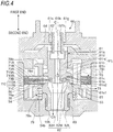
- Fig. 4 is an enlarged cross-sectional view illustrating the configuration of the control valve portion 60 of the damping force generating device 40.
- the large diameter portion 52 is provided with a recess portion 54 which is recessed toward the small diameter portion 51 side.
- a boss portion 55 which is raised from a bottom surface 54b of the recess portion 54 is formed.
- a cylindrical portion 52t is formed on the first end 40a side so as to further expand on the outer peripheral side and extend to the first end 40a (upper part of Fig. 4 , see Fig. 3 ) side.
- the large diameter portion 52 is formed with a flow passage hole 56 penetrating the inside and outside thereof.
- the flow passage hole 56 is formed on an outer peripheral side of a valve body 70 of the control valve portion 60 described below.
- valve seat member 50 is formed with a central flow passage 106 which makes a tip portion 51s on the second end 40b side of the small diameter portion 51 and the boss portion 55 of the large diameter portion 52 communicate with each other.
- valve seat member 50 In such a valve seat member 50, the cylindrical portion 52t and a part of the large diameter portion 52 on the first end 40a side are inserted into the cartridge case 41 and the second end 40b side of the large diameter portion 52 and the main damper 42 held by the small diameter portion 51 project outward from the cartridge case 41.
- the extension side valve seat member 44 and the compression side valve seat member 48 of the main damper 42 are respectively provided with annular seal rings 44s and 48s on their outer peripheral surfaces.
- respective seal rings 44s and 48s hit the inner peripheral surface of the damper holding portion 27, whereby the first oil chamber S11, the second oil chamber S12, and the third oil chamber S13 are formed between the damper holding portion 27 and the main damper 42.
- the first oil chamber S11 is formed further on the first end 40a side than the seal ring 48s of the compression side valve seat member 48.
- the second oil chamber S12 is formed between the seal ring 44s of the extension side valve seat member 44 and the seal ring 48s of the compression side valve seat member 48.
- the third oil chamber S13 is formed between the bottom on the second end 40b side of the damper case 16 and the seal ring 44s of the extension side valve seat member 44.
- the tip portion 51s of the small diameter portion 51 of the valve seat member 50 is arranged in the third oil chamber S13 of the damper case 16 and the third oil chamber S13 and a central flow passage 106 formed in the small diameter portion 51 communicate with each other.
- the communication passage 107 communicating with the oil reservoir chamber S3 in the reservoir 30 is formed between the compression side valve seat member 48 and the extension side valve seat member 44 at a position facing the second oil chamber S12.
- the control valve portion 60 is an example of a valve mechanism.
- the control valve portion 60 includes a drive valve 61, a solenoid actuator 62 which drives the drive valve 61, an annular valve body holder 64 fitted inside the cylindrical portion 52t, the valve body 70 accommodated in the recess portion 54, and an orifice collar 80 arranged so as to be able to come into contact with the valve body 70.
- the control valve portion 60 is provided with a valve collar 78 and a coil spring 79 arranged between the valve collar 78 and the orifice collar 80.
- the drive valve 61 is provided on the valve body holder 64 so as to be movable along the central axis C direction of the damping force generating device 40.
- the drive valve 61 is arranged on an opposite side (the drive valve 61 is above the valve body 70 and the orifice collar 80 is below the valve body 70) of the orifice collar 80 from the valve body 70.
- the drive valve 61 includes a shaft portion 61j having a flow passage 61h formed in the central axis C direction therein and a first step portion 61b extending from an outer peripheral surface 61a of the shaft portion 61j to the radial outside of the shaft portion 61j.
- the flow passage 61h is a through hole penetrating in the central axis C direction. Therefore, the shaft portion 61j has a substantially cylindrical shape as a whole by the outer peripheral surface 61a and the flow passage 61h.
- the outer peripheral surface 61a is the outer surface of the cylinder and the flow passage 61h is the inner peripheral surface or the inner surface of the cylinder.
- the shaft portion 61j has a rod accommodating portion 61s which is recessed toward the tip portion side at the rear end portion on the first end 40a side.
- the drive valve 61 has an annular first step portion 61b protruding from the outer peripheral surface 61a in a direction intersecting with the central axis C direction (axial direction).
- the first step portion 61b is an annular portion protruding from the outer peripheral surface 61a in a direction substantially perpendicular to the central axis C direction and continuing to the outer peripheral surface 61a.
- the drive valve 61 forms an accommodation portion 61k by the first step portion 61b.
- a spoke valve 71A which will be described below, which is a part of the valve body 70, is accommodated in the accommodation portion 61k.
- the direction in which the first step portion 61b projects from the outer peripheral surface 61a is also the direction along which the oil flows. That is, the first step portion 61b projects in a direction substantially perpendicular to the central axis C direction, and thus a part of the valve body 70, which is arranged in a direction substantially perpendicular to the central axis C direction, is accommodated without a gap and the flow of oil is not easily obstructed.
- the drive valve 61 presses the valve body 70 the first step portion 61b presses the spoke valve 71A and the spoke valve 71A elastically deforms toward the orifice collar 80 side.
- the shaft portion 61j includes a protruding portion 61c which further protrudes toward the second end 40b side (orifice collar 80 side) than the first step portion 61b and a base portion 61m extending toward the opposite side of the protruding portion 61c with respect to the first step portion 61b and having a larger outer peripheral diameter than the outer diameter of the protruding portion 61c.
- the protruding portion 61c has a cylindrical shape because it has the above-described flow passage 61h inside.
- the protruding portion 61c has a role of flowing oil in the central axis C direction.
- the oil flows from the radial outside of the shaft portion 61j toward the outer peripheral surface 61a along the first step portion 61b, then changes the direction along the protruding portion 61c and flows toward the second end 40b side, and then flows toward the central flow passage 106.
- the protruding portion 61c changes the direction of the oil flow from the radial direction of the shaft portion 61j to the central axis C direction. Therefore, it can be said that the protruding portion 61c is an oil direction changing portion for flowing the oil toward the central flow passage 106.
- oil flows in the opposite direction.
- the protruding portion 61c is an oil direction changing portion for changing the flow of oil from the central axis C direction to the radial direction of the shaft portion 61j. Therefore, it can be said that the protruding portion 61c is also formed along the direction along which the oil flows.
- the drive valve 61 has a communication hole 61d which connects the outer peripheral surface of the protruding portion 61c of the shaft portion 61j and the flow passage 61h.
- Fig. 5 is a diagram illustrating the communication hole 61d and is a diagram illustrating the drive valve 61 in a cross section different from that in Fig. 4 .
- the communication hole 61d is an oblique hole which extends from the outer peripheral surface of the protruding portion 61c in a direction oblique to the central axis C direction (axial direction) and communicates with the flow passage 61h.
- the communication hole 61d is an oblique hole which is linearly formed obliquely from the outer peripheral surface of the protruding portion 61c toward the first end 40a.
- the communication hole 61d is open to the flow passage 61h at a portion closer to the protruding portion 61c than the base portion 61m.
- the communication hole 61d is an oblique hole in which a second opening 61d2 opening on the outer peripheral surface of the protruding portion 61c is arranged further on the second end 40b side (orifice collar 80 side) than a first opening 61d1 opening on the flow passage 61h.
- the drive valve 61 has a second step portion 61e extending from the outer peripheral surface of the protruding portion 61c to the outside in the radial direction of the protruding portion 61c.
- the second step portion 61e is formed in an annular shape around the central axis C and the outer diameter of the second step portion 61e is smaller than the outer diameter of the first step portion 61b.
- the second step portion 61e has an annular recess portion 61e1 on the end surface on the second end 40b side (orifice collar 80 side). As illustrated in Fig.
- the angle ⁇ formed by a plane having the central axis C as a normal direction and an inclined surface on an apex portion 61e2 side of the recess portion 61e1 facing the orifice collar 80 is preferably 10° or more and 30° or less (10° ⁇ 30°), and particularly preferably 20°.
- the second step portion 61e faces a spoke valve 71B of the valve body 70 which is arranged further on the second end 40b side (orifice collar 80 side) than the spoke valve 71A of the valve body 70 described below in detail.
- the second step portion 61e is not in contact with the spoke valve 71B when the drive valve 61 does not press the valve body 70.
- the second step portion 61e comes into contact with the spoke valve 71B and the second step 61e presses the spoke valve 71B, and further the spoke valve 71B elastically deforms toward the second end 40b side (orifice collar 80 side).
- the recess portion 61e1 is formed in the second step portion 61e, the apex portion 61e2 of the second step portion 61e comes into contact with the spoke valve 71B.
- the solenoid actuator 62 is an example of a drive unit which moves the drive valve 61 in the axial direction.
- the solenoid actuator 62 is provided in the cartridge case 41 as illustrated in Fig. 3 . Further, the solenoid actuator 62 includes two cores 65A and 65B, a coil 66, a rod 67, and a plunger 68.
- the core 65A has a bottomed tubular shape having a recess portion 65c and the core 65B has a bottomed tubular shape having a recess portion 65d.
- the two cores 65A and 65B are provided with the recess portions 65c and 65d facing each other, thereby forming a plunger chamber 69 continuous in the central axis C direction.
- the rod 67 extends along the central axis C direction.
- the rod 67 is slidably held along the central axis C direction by a guide bush 65g provided on one core 65A and a guide bush 65h provided in a recess portion formed on the other core 65B.
- the rod 67 has a through hole 67h penetrating in the central axis C direction.
- the tip portion of the rod 67 on the second end 40b side is inserted into the rod accommodating portion 61s provided in the drive valve 61.
- the outer diameter of the rod 67 is smaller than the inner diameter of the rod accommodating portion 61s, whereby a cylindrical gap 61g is formed with respect to the rod 67 in the rod accommodating portion 61s.
- the rod 67 has a communication hole (not illustrated) for communicating the inside of the through hole 67h and the gap 61g at the tip portion on the second end 40b side.
- a back pressure chamber 65r which spreads to the outer peripheral side of the rod 67 is formed.
- the back pressure chamber 65r communicates with the gap 61g and further communicates with the inside of the through hole 67h of the rod 67 through a communication hole (not illustrated).
- Such a solenoid actuator 62 adjusts the electromagnetic force generated in the coil 66 by increasing/decreasing the current applied to the coil 66, so that the rod 67 moves back and forth in the central axis C direction.
- the position of the drive valve 61 can be adjusted in the central axis C direction. That is, the solenoid actuator 62 generates a thrust force which presses the drive valve 61 toward the second end 40b when a current is applied to the coil 66.
- the drive valve 61 presses the valve body 70 toward the second end 40b due to this thrust force and the pressure of the oil flowing into the back pressure chamber 65r.
- Fig. 6 is a diagram illustrating the configuration of the valve body 70.
- valve body 70 in addition to the valve body 70, the drive valve 61 and the valve collar 78 are also illustrated.
- the illustrated valve body 70 is a member having a cylindrical shape as a whole.
- the valve body 70 is arranged so that its center substantially coincides with the central axis C.
- the valve body 70 has the spoke valve 71A, a spacer 73A, a protective valve 710A, the spoke valve 71B, a protective valve 710B, a spacer 73B, and a spoke valve 71C, which are sequentially stacked from the first end 40a to the second end 40b.
- the spoke valve 71A, the spoke valve 71B, and the spoke valve 71C are stacked in the direction in which the solenoid actuator 62 presses the drive valve 61.
- the valve body 70 includes a plurality of axially stacked valve bodies (three spoke valves 71A, 71B, and 71C), the spacers (spacers 73A and 73B arranged between the spoke valves adjacent to each other in the stacking direction) arranged between the valve bodies adjacent to each other in the stacking direction, and the protective valves (710A and 710B disposed so as to interpose the spoke valve 71B) disposed in contact with the spoke valve 71B.
- the case where three spoke valves are stacked in the axial direction is illustrated, but the invention can be configured to include four or more spoke valves stacked in the axial direction.
- the spoke valve 71A is an example of a first spoke valve located at the upper end of the plurality of valve bodies on the first end 40a side. It can also be said that the spoke valve 71A is located closest to the drive valve 61 side among the three spoke valves 71A, 71B, and 71C.
- the spoke valve 71A includes an outer frame portion 74 formed in an annular shape, an inner frame portion 75 formed annularly on the inner side in the radial direction with respect to the outer frame portion 74, and a plurality of spoke portions 72S connecting the outer frame portion 74 and the inner frame portion 75. As a result, a central hole 76 is formed inside the inner frame portion 75.
- a plurality of the spoke portions 72S are arranged apart from each other, and in the embodiment, three spoke portions 72S are arranged at equal intervals in the circumferential direction. That is, one spoke portion 72S is arranged every 120° in the circumferential direction.
- three opening portions 77 are formed between the adjacent spoke portions 72S in the circumferential direction.
- the central hole 76 and the opening portion 77 are an example of a through hole provided in the valve body 70 and penetrating in the axial direction.
- the spoke valve 71B is an example of a second spoke valve arranged further on the second end 40b side (orifice collar 80 side) than the spoke valve 71A.
- the spoke valve 71C is located at the lower end portion on the second end 40b side.
- the spoke valve 71C is an example of a third spoke valve which is arranged so as to come into contact with the end face in the central axis C direction of the orifice collar 80 which is a tubular body. It can also be said that the spoke valve 71C is located closest to the orifice collar 80 side among the three spoke valves 71A, 71B, and 71C.
- the outer frame portion 74 and the spoke portion 72S of the spoke valve 71B and the outer frame portion 74 and the spoke portion 72S of the spoke valve 71C have the same configurations as the outer frame portion 74 and the spoke portion 72S of the spoke valve 71A, as illustrated in the drawing.
- the inner frame portion 75 of the spoke valve 71B is formed radially inward of the inner frame portion 75 of the spoke valve 71A. That is, the inner frame portion 75 of the spoke valve 71B is smaller in size than the inner frame portion 75 of the spoke valve 71A. As a result, the central hole 76 of the spoke valve 71B is smaller than the central hole 76 of the spoke valve 71A.
- the inner frame portion 75 of the spoke valve 71C is formed radially outside the inner frame portion 75 of the spoke valve 71A. That is, the inner frame portion 75 of the spoke valve 71C is larger in size than the inner frame portion 75 of the spoke valve 71A. As a result, the central hole 76 of the spoke valve 71C is larger than the central hole 76 of the spoke valve 71A.
- the size of the central hole 76 becomes smaller in the order of the spoke valve 71C, the spoke valve 71A, and the spoke valve 71B.
- the spoke valve 71A and the spoke valve 71C are formed by stacking a plurality of plate-shaped members having the same shape. In the embodiment, the spoke valve 71A and the spoke valve 71C are respectively formed by stacking three plate-shaped members.
- the spoke valve 71B is not a stacked body like this, but a single plate-shaped member.
- the inner frame portion 75 of the spoke valve 71A has an upper surface, which is a surface on the first end 40a side, accommodated in the accommodation portion 61k of the drive valve 61. That is, the diameter of the central hole 76 of the spoke valve 71A is substantially equal to the outer diameter of the accommodation portion 61k of the drive valve 61, and the inner peripheral surface of the central hole 76 and the accommodation portion 61k are in contact with each other.
- the upper surface of the inner frame portion 75 of the spoke valve 71B which is the surface on the first end 40a side, faces the second step portion 61e of the drive valve 61.
- the inner frame portion 75 of the spoke valve 71C is placed on an orifice collar 80 and the valve collar 78, which will be described below.
- each of the spoke valve 71A, the spoke valve 71B, and the spoke valve 71C functions as a part of a flow passage through which oil flows. It can also be said that the opening portion 77 is a flow passage in the central axis C direction in the valve body 70.
- the axial gap between the spoke valve 71A and the spoke valve 71B functions as a gap flow passage 110A which allows oil to flow therethrough.
- the axial gap between the spoke valve 71B and the spoke valve 71C also functions as a gap flow passage 110B which allows oil to flow therethrough.
- the gap flow passage 110A and the gap flow passage 110B are a part of the flow passage formed in the valve body 70 and can be said to be radial flow passages in the valve body 70.
- gap flow passage 110A and the gap flow passage 110B are not distinguished from each other, they may be simply referred to as "gap flow passage 110".
- the spacer 73A has an annular shape and is arranged between the spoke valve 71A and the spoke valve 71B to adjust the gap between the spoke valve 71A and the spoke valve 71B. Thereby, the flow passage area of the gap flow passage 110A between the spoke valve 71A and the spoke valve 71B is adjusted. Further, since the protective valve 710A is provided between the spoke valve 71A and the spoke valve 71B, the spacer 73A is arranged so as to be interposed between the spoke valve 71A and the protective valve 710A.
- the spacer 73B also has an annular shape and is arranged between the spoke valve 71B and the spoke valve 71C to adjust the gap between the spoke valve 71B and the spoke valve 71C. Thereby, the flow passage area of the gap flow passage 110B between the spoke valve 71B and the spoke valve 71C is adjusted. Further, since the protective valve 710B is provided between the spoke valve 71B and the spoke valve 71C, the spacer 73B is arranged so as to be interposed between the protective valve 710B and the spoke valve 71C.
- the spacer 73A and the spacer 73B are arranged so as to be respectively located between the outer frame portions 74 of the spoke valves 71A, 71B, and 71C which are adjacent to each other in the stacking direction. That is, the spacer 73A and the spacer 73B have the same shape and size as the outer frame portions 74 of the spoke valves 71A, 71B, and 71C and are interposed between the outer frame portions 74 adjacent in the stacking direction, so the spacers 73A and spacers 73B adjust the distance between the spoke valve 71A and the spoke valve 71B and the distance between the spoke valve 71B and the spoke valve 71C.
- the protective valve 710A is interposed between the spacer 73A and the spoke valve 71B. Further, the protective valve 710B is interposed between the spoke valve 71B and the spacer 73B. That is, the protective valves 710A and 710B are arranged in contact with the spoke valve 71B and are arranged so as to interpose the spoke valve 71B.
- the protective valve 710B protects the spoke portion 72S when the spoke portion 72S of the spoke valve 71C is deformed.
- the protective valves 710A and 710B are claw valves which include the outer frame portion 74 formed in a ring shape and a claw portion 711 which protrudes inward from the outer frame portion 74 and is formed at a position corresponding to the spoke portion 72S of the spoke valve 71B.
- the outer frame portions 74 of the protective valves 710A and 710B have the same shape and size as the outer frame portions 74 of the spoke valve 71B and the spacers 73A and 73B. Therefore, the outer frame portion 74 of the protective valve 710A is interposed between the outer frame portions 74 of the spacer 73A and the spoke valve 71B. Further, the outer frame portion 74 of the protective valve 710B is interposed between the outer frame portions 74 of the spoke valve 71B and the spacer 73B.
- three spoke portions 72S of the spoke valve 71B are arranged at equal intervals in the circumferential direction. Therefore, three claw portions 711 of the protective valve 710A or 710B formed at positions corresponding to the spoke portion 72S are also arranged at equal intervals in the circumferential direction. That is, one claw 711 is arranged every 120° in the circumferential direction of the protective valves 710A and 710B.
- the protective valve 710B protects a connecting portion 713 between the outer frame portion 74 and the spoke portion 72S of the spoke valve 71C by those claw portions 711.
- the protective valve 710A can be regarded as a gap adjusting member which adjusts the gap between the spoke valve 71A and the spoke valve 71B together with the spacer 73A.
- the protective valve 710B, together with the spacer 73B can be regarded as a gap adjusting member which adjusts the gap between the spoke valve 71B and the spoke valve 71C. That is, the protective valves 710A and 710B adjust the gap between the adjacent spoke valves in the stacking direction, as similar to the spacers 73A and 73B.
- the valve collar 78 is an example of a positioning member for the spoke valves 71A, 71B, and 71C and the protective valves 710A and 710B of the valve body 70.
- the valve collar 78 includes a first recess portion 78a arranged at a position corresponding to the spoke portions 72S of the spoke valves 71A, 71B, and 71C and the claw portions 711 of the protective valves 710A and 710B in the circumferential direction.
- the three spoke portions 72S are arranged at equal intervals in the circumferential direction
- the three first recess portions 78a are provided at equal intervals in the circumferential direction.
- valve collar 78 is provided with a convex portion 78b which protrudes with respect to the first recess portion 78a between the adjacent first recess portions 78a in the circumferential direction.
- the three convex portions 78b provided at equal intervals in the circumferential direction penetrate the opening portions 77 of the spoke valves 71A, 71B, and 71C.
- the spoke valves 71A, 71B, and 71C and the protective valves 710A and 710B can be positioned in the circumferential direction.
- the valve collar 78 has a mounting portion 78d.
- the inner frame portion 75 of the spoke valve 71C is mounted on the mounting portion 78d.
- the spoke valves 71A, 71B, and 71C can be positioned in the direction of the central axis C.
- the convex portion 78b of the valve collar 78 has a second recess portion 78c which is recessed and formed above the first recess portion 78a. Then, as illustrated by the dotted line L1 in Fig. 4 , the upper surface of the first recess portion 78a and the upper surface of the second recess portion 78c are on the same slope.
- each convex portion 78b of the valve collar 78 is provided. Therefore, there are six recess portions between the respective convex portions 78b, including the above-described first recess portion 78a and second recess portion 78c. It can be said that there are recess portions at equal intervals every 60° in the circumferential direction. Therefore, when the recess portions with a uniform depth are created, when assembling the valve body 70, in some cases, the spoke portions 72S of the spoke valves 71A, 71B, and 71C and the claw portions 711 of the protective valve 710B may enter a recess portions which are 60° circumferentially displaced from the recess portions where the spoke portions or the claw portions should enter.
- the recess portion such as the first recess portion 78a where the spoke portion or the claw portion should originally enter is formed deep and the recess portion such as the second recess portion 78c where the spoke portion or the claw portion should not enter is formed shallow.
- the deeply formed recess portions and the shallowly formed recess portions are alternately arranged in the circumferential direction as illustrated in the drawing and the deeply formed recess portions are arranged every 120° in the circumferential direction. Therefore, at the time of assembly, it becomes easy to accommodate the spoke portion 72S and the claw portion 711 in the recess portion where the spoke portion or the claw portion should originally enter.
- the spoke valve 71C and the upper surface of the first recess portion 78a do not come into contact with each other.
- the inner frame portion 75 of the spoke valve 71C is mounted on the mounting portion 78d. That is, by setting the upper surface of the first recess portion 78a to be an inclined surface separately from the mounting portion 78d, the inner frame portion 75 of the spoke valve 71C is mounted on the mounting portion 78d, and thus the sealing property between the spoke valve 71C and the valve collar 78 can be secured.
- the first recess portion 78a and the second recess portion 78c can be machined together by using a circular cutter or milling cutter, which makes the manufacture of the valve collar 78 easier.
- the coil spring 79 is provided in a compressed state in the recess portion 78e provided on the second end 40b side of the valve collar 78.
- the drive valve 61 presses the valve body 70, the coil spring 79 is pressed via the valve body 70 and the valve collar 78, so that the coil spring 79 is maintained in a compressed state.
- the orifice collar 80 is an example of a tubular body and is arranged so as to face the drive valve 61 with the valve body 70 interposed therebetween.
- the orifice collar 80 has an upper step portion 81 for coming in contact with and accommodating the valve body 70 on the end surface on the first end 40a side in the central axis C direction.
- the valve body 70 is accommodated in the orifice collar 80 in a state where the end surface of the upper step portion 81 on the side of the first end 40a in the central axis direction is in contact with the end surface of the inner frame portion 75 of the spoke valve 71C on the side of the orifice collar 80.
- the orifice collar 80 has a through hole 82 as a hollow portion penetrating in the axial direction.
- the through hole 82 allows oil to flow in the central axis C direction (axial direction) inside the orifice collar 80.
- the through hole 82 is composed of an upper through hole 82H located on the upper side which is the first end 40a side, a lower through hole 82L located on the lower side which is the second end 40b side, and a middle through hole 82M connecting the upper through hole 82H and the lower through hole 82L.
- the flow passages of the upper through hole 82H and the lower through hole 82L have a constant diameter in the central axis C direction (axial direction).
- the central through hole 82M has an orifice shape whose diameter decreases along the central axis C direction (axial direction) as the distance from the valve body 70 increases.
- the middle through hole 82M is an orifice portion whose inner diameter increases as it approaches the valve body 70.
- the diameter of the first end 40a side end of the middle through hole 82M is set to be the same as the diameter of the upper through hole 82H and the diameter of the second end 40b side end of the middle through hole 82M is set to be the same as the diameter of the lower through hole 82L, in such a manner that the upper through hole 82H, the middle through hole 82M, and the lower through hole 82L are continuously connected.
- the tip of the protruding portion 61c on the side of the second end 40b is arranged so as to enter the inside of the through hole 82 of the orifice collar 80.
- the middle through hole 82M of the through hole 82 is not formed into an orifice shape, the distance between the protruding portion 61c and the inner peripheral surface of the through hole 82 becomes small, and thus oil circulation is likely to be hindered.
- the middle portion through hole 82M that is the orifice portion is provided, the oil can flow more smoothly.
- the orifice collar 80 is not integrated with the valve seat member 50 and is formed as a separate member, it becomes easier to use the orifice collar 80 in which the diameter of the opening of the upper through hole 82H is changed, so the attenuation characteristic can be easily changed.
- the orifice collar 80 can be easily replaced by, for example, screwing it onto the valve seat member 50.
- the oil in the piston-side oil chamber S1 is compressed by the piston 12. Then, the oil in the piston-side oil chamber S1 is sent from the oil hole 102 formed in the damper case 16 to the first oil chamber S11 formed in the damper holding portion 27. As indicated by the arrow C1 in Fig. 3 , the oil sent into the first oil chamber S11 passes through the compression side inlet oil passage 48c formed in the compression side valve seat member 48 of the main damper 42, and then the oil pushes open the compression side damping valve 47 provided on the outlet side and flows into the second oil chamber S12. In this case, the compression side damping valve 47 is pushed open to allow the oil to pass through the gap formed between the outlet of the compression side inlet oil passage 48c and the compression side damping valve 47, whereby a damping force is generated.
- the oil flowing into the third oil chamber S13 passes through the flow passage 105 formed in the damper case 16, and then the oil flows from the oil hole 104 formed at the upper end potion of the outer cylinder 15 into the cylindrical flow passage 101 formed between the inner cylinder 14 and the outer cylinder 15.
- the oil which flows into the flow passage 101 passes through the oil hole 103 and flows into the rod-side oil chamber S2. In this way, the oil flows into the rod-side oil chamber S2, by the oil flowing into the rod-side oil chamber S2, when the piston rod 13 enters the cylinder 11, the amount of oil corresponding to the entry volume of the piston rod 13 is compensated.
- the oil flowing into the large diameter portion 52 passes through the opening portions 77 formed in the spoke valve 71B and the spoke valve 71C, the gap flow passage 110, and the central holes 76 formed in the spoke valve 71B and the spoke valve 71C, and then the oil flows into the through hole 82 of the orifice collar 80. After that, the oil which flows into the through hole 82 passes through the central flow passage 106 formed in the valve seat member 50 and flows into the third oil chamber S13.
- a damping force is generated by the resistance generated when the oil flowing through the path indicated by the arrow C5 passes through the gap flow passage 110.
- the oil in the rod-side oil chamber S2 is compressed by the piston 12. Then, the oil in the rod-side oil chamber S2 passes through the oil hole 103 formed at the lower end portion of the inner cylinder 14 and flows into the cylindrical flow passage 101 formed between the inner cylinder 14 and the outer cylinder 15. The oil flowing through the flow passage 101 is sent from the oil hole 104 formed at the upper end potion of the outer cylinder 15 through the flow passage 105 formed in the damper case 16 to the third oil chamber S13 of the damping force generating device 40.
- the oil sent to the third oil chamber S13 flows into the extension side inlet oil passage 44t of the extension side valve seat member 44 and the extension side damping valve 45 provided on the outlet side is pushed open to generate a damping force.
- the oil flowing into the second oil chamber S12 passes through the extension side outlet oil passage 48t of the compression side valve seat member 48, pushes the extension side outlet check valve 49 open, and flows into the first oil chamber S11.
- the oil flowing into the first oil chamber S11 flows into the piston-side oil chamber S1 from the oil hole 102 formed in the damper case 16. In this way, the oil flows into the piston-side oil chamber S1 to compensate the oil amount corresponding to the withdrawal volume of the piston rod 13 when the piston rod 13 withdraws from the cylinder 11.
- the oil flowing into the through hole 82 in this way passes through the central holes 76 formed in the spoke valve 71A and the spoke valve 71B from the through hole 82 of the orifice collar 80, as indicated by the arrow T5 in Fig. 4 .
- the oil passing through the central hole 76 passes through the gap flow passage 110 and the opening portions 77 formed in the spoke valve 71B and the spoke valve 71C, and then the oil flows into the first oil chamber S11 through the flow passage hole 56 formed in the large diameter portion 52 of the valve seat member 50.
- a damping force is generated by the resistance generated when the oil flowing through the path indicated by the arrow T5 passes through the gap flow passage 110.
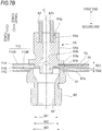
- Figs. 7A and 7B are cross-sectional views comparing before and after displacing the drive valve 61 to the valve body 70 side by the thrust force of the solenoid actuator 62.
- Fig. 7A illustrates a state before displacing the drive valve 61 to the valve body 70 side
- Fig. 7B illustrates a state after displacing the drive valve 61 to the valve body 70 side.
- a width R11 of the gap flow passage 110A between the spoke valve 71A and the spoke valve 71B and a width R12 of the gap flow passage 110B between the spoke valve 71B and the spoke valve 71C are substantially uniform in the radial direction of each spoke valve.
- the width R11 and the width R12 are respectively the thicknesses of the spacer 73A and the spacer 73B.
- the accommodation portion 61k of the drive valve 61 presses the inner frame portion 75 of the spoke valve 71A, and subsequently, the second step portion 61e of the drive valve 61 presses the inner frame portion 75 of the spoke valve 71B.
- the respective spoke portions 72S of the spoke valve 71A and the spoke valve 71B are mainly elastically deformed and the inner frame portions 75 of the spoke valve 71A and the spoke valve 71B move to the second end 40b side. That is, in this case, it moves downward in the drawing.
- the outer frame portions 74 of the spoke valve 71A and the spoke valve 71B are hardly deformed. Further, since there is the spacer 73A between the outer frame portion 74 of the spoke valve 71A and the outer frame portion 74 of the spoke valve 71B, the distance between the spoke valve 71A and the spoke valve 71B does not change at this point.
- the inner frame portion 75 of the spoke valve 71A moves toward the second end 40b side by being pressed and elastically deformed. Further, the inner frame portion 75 of the spoke valve 71B moves toward the second end 40b side by being pressed and elastically deformed after the second step portion 61e comes into contact with the spoke valve 71B.
- the inner frame portion 75 of the spoke valve 71B moves later than the inner frame portion 75 of the spoke valve 71A.
- the gap of the gap flow passage 110A between the spoke valve 71A and the spoke valve 71B becomes smaller than R11 and becomes R21 illustrated in Fig. 7B . That is, the inner frame portions 75 of the spoke valve 71A and the spoke valve 71B are pressed and elastically deformed, so that the flow passage area of the gap flow passage 110A is reduced.
- valve body 70 is configured such that, by elastically deforming the inner peripheral portion of the valve body 70, which comes into contact with the drive valve 61 that has moved in a direction toward the valve body 70, relative to the outer peripheral portion of the valve body 70, in the direction toward the orifice collar 80, the gap between the plurality of valve bodies 70 can be changed.
- the inner frame portion 75 of the spoke valve 71C does not move because it is not pressed, but the inner frame portion 75 of the spoke valve 71B moves by being pressed and elastically deformed. Therefore, the gap of the gap flow passage 110B between the inner frame portion 75 of the spoke valve 71B and the inner frame portion 75 of the spoke valve 71C becomes smaller than R12 and becomes R22 illustrated in Fig. 7B . That is, the inner frame portions 75 of the spoke valve 71A and the spoke valve 71B are pressed and elastically deformed, so that the flow passage area of the gap flow passage 110B is reduced.
- the damping force generated when the oil passes through the gap flow passage 110 is the force in a direction to move the drive valve 61 to the valve opening side. That is, when the oil passes through the gap flow passage 110, a drag force against the force that displaces the drive valve 61 to the valve body 70 side by the solenoid actuator 62 is generated.
- This drag force is a force that tends to separate the second step portion 61e from the spoke valve 71B in the compression side stroke and the pressure receiving area, which is the area to which this drag force is exerted, is the area of the circle at the second step portion 61e. That is, it is the area of a circle of a diameter M1 illustrated in Fig. 7A .
- the above-described drag force is a force in a direction to separate the spoke valve 71B from the orifice collar 80 in the extension side stroke and the pressure receiving area, which is the area to which this drag force is exerted, is the area of the circle of the opening of the upper through hole 82H of the orifice collar 80. That is, it is the area of a circle of a diameter M3 illustrated in Fig. 7A .
- the drive valve 61 is formed with a through hole 61h communicating in the central axis C direction. Further, a communication hole which communicates the inside of the through hole 67h with the gap 61g of the drive valve 61 is formed at the tip of the rod 67 and the back pressure chamber 65r is further formed at the tip thereof. Therefore, the oil can wrap around behind the drive valve 61, which produces a force (back pressure) in a direction to cancel the above-described drag force.
- the second end 40b side of the drive valve 61 and the back pressure chamber 65r communicate with each other through the flow passage 61h.
- the pressure receiving area which is the area exerting the back pressure, is the area of the circle at an outer peripheral portion 61a. This is the area of the circle of a diameter M2 illustrated in Fig. 7A .
- the annular area which is the difference between the area of the circle having the diameter M1 and the area of the circle having the diameter M2
- the annular area which is the difference between the area of the circle having the diameter M2 and the area of the circle having the diameter M3
- the contact area between the second step portion 61e and the valve body 70 is reduced by providing the apex portion 61e2 in the second step portion 61e.
- the drive valve 61 moves to the valve opening side.
- the second step portion 61e and the spoke valve 71B are separated from each other to form a first gap
- the spoke valve 71B and the orifice collar 80 are separated from each other to form a second gap.
- the second step portion 61e and the spoke valve 71B can be brought into contact with each other, and in the extension side stroke, the spoke valve 71B and the orifice collar 80 can be brought into contact with each other.
- the increased flow passage area can be reduced. That is, according to the invention, the flow passage area can be increased or decreased by the damping pressure.
- the oil which flows due to the sliding of the piston 11 flows into the control valve portion 60 to generate a damping force.
- the higher drag force is when the oil flows through the gap flow passage 110 at high speed, for example, this is a case where the wheels are abruptly displaced in the vertical direction due to the unevenness of the road surface, or the like and the piston 12 is displaced at a high speed in the cylinder 11.
- the drag force becomes large, the first gap and the second gap tend to become large.
- the damping force can be adjusted by the thrust force of the solenoid actuator 62 pressing the drive valve 61. That is, the smaller the thrust force with which the solenoid actuator 62 presses the drive valve 61, the greater the drag force becomes than the thrust force. Therefore, the first gap and the second gap tend to become large and the damping force becomes small. On the other hand, as the thrust force with which the solenoid actuator 62 presses the drive valve 61 is larger, the drag force is less likely to be larger than the thrust force, so that the first gap and the second gap are likely to be small, and thus the damping force is large.
- the valve body 70 is highly accurately positioned by the valve collar 78. Further, the positions between the spoke valves 71A, 71B and 71C and the spacers 73A and 73B which form the valve body 70 are also positioned with high accuracy. Therefore, the flow passage area of the gap flow passage 110 can be determined with high accuracy, and thus the damping force generated in the gap flow passage 110 can be adjusted with higher precision.
- the oil flow passages are different between the compression side stroke and the extension side stroke, it is possible to adjust the damping force independently in each of the compression side stroke and the extension side stroke by changing the thickness of the spacer 73A and the spacer 73B, for example.
- the spoke valves 71A, 71B, 71C, the spacers 73A, 73B, and the protective valves 710A, 710B are plate-shaped members and can be easily formed by punching the plate material by pressing or the like. Further, the plate thickness accuracy can be easily increased by using the plate-shaped member. Further, those plate-shaped members have no directivity with respect to the front and back sides. As a result, when assembling, it is possible to stack without worrying about the front and back sides, and thus the assembling property of the valve body 70 is improved.
- the protective valve 710B protects the spoke portion 72S of the spoke valve 71C in the compression side stroke.
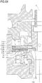
- Fig. 8A is a view illustrating a state of the spoke valve 71C when the protective valves 710A and 710B are provided in the compression side stroke.
- Fig. 8B is a diagram illustrating a state of the spoke valve 71C when the protective valves 710A and 710B are not provided in the compression side stroke.
- the protective valve 710B is provided to protect the connecting portion 713 of the spoke valve 71C.
- the protective valve 710B includes the claw portion 711 as described above. Then, as illustrated in Fig. 8A , when the spoke valve 71C is bent by the pressure of the oil, the spoke portion 72S comes into contact with the claw portion 711 of the protective valve 710B. As a result, excessive bending of the spoke valve 71C is suppressed and bending of the connecting portion 713 is also suppressed. As a result, the spoke valve 71C can be protected.
- the oil flows from the through hole 82 of the orifice collar 80 into the valve body 70 and comes into contact with the spoke valve 71A.
- the piston 12 is less likely to be displaced in the cylinder 11 at a high speed, and the oil is further less likely to flow at a high speed. Therefore, there is little need to protect the spoke valve 71A with the protective valve 710A. Therefore, the protective valve 710A does not necessarily have to be provided. That is, the protective valve needs to be arranged on the spoke valve 71C side with respect to the spoke valve 71B, but not necessarily on the spoke valve 71A side.
- the invention is not limited to this embodiment and it is possible to arrange the protective valve 710A also on the spoke valve 71A side and protect the spoke valve 71A with the protective valve 710A.
- the protective valve 710A when the protective valve 710A is not provided, the axial symmetry of each member forming the valve body 70 is lost. That is, when the protective valve 710A is provided, it becomes symmetrical in the axial direction about the spoke valve 71B, whereas when the protective valve 710A is not provided, this symmetry cannot be maintained. Without this symmetry, in the assembly process of the valve body 70, it is necessary to confirm that the protective valve 710A is not provided on the spoke valve 71A side in the axial direction around the spoke valve 71B, but the protective valve 710B is provided on the spoke valve 71C side, which lowers the assembling property. Therefore, it is more preferable to provide the protective valve 710A in order to improve the assembling property.
- the first step portion 61b is in contact with the spoke valve 71A.
- the first step portion 61b and the spoke valve 71A do not have to be in contact with each other when the drive valve 61 is not pressed. That is, the first step portion 61b and the spoke valve 71A may be separated from each other, and there may be a gap between the first step portion 61b and the spoke valve 71A.
- the drive valve 61 moves to the second end 40b side (orifice collar 80 side) to bring the separated first step portion 61b into contact with the spoke valve 71A. From this state, when the drive valve 61 moves toward the orifice collar 80 side, the spoke valve 71A is pressed by the first step portion 61b and the spoke valve 71A elastically deforms. Further, when the drive valve 61 moves to the orifice collar 80 side, the second step portion 61e comes into contact with the spoke valve 71B. Then, the second step portion 61e presses the spoke valve 71B and the spoke valve 71B elastically deforms toward the second end 40b side (orifice collar 80 side).
- the configuration of the invention is not limited to the embodiment as long as the operation and effects of the invention are exhibited.
- a configuration in which the oil flow in the compression side stroke and the oil flow in the extension side stroke are opposite to each other, that is, the oil flow in the extension side stroke is the arrow C5 in Fig. 4 and the oil flow in the compression side stroke is the arrow T5 in Fig. 4 can be applied.
Landscapes
- Engineering & Computer Science (AREA)
- General Engineering & Computer Science (AREA)
- Mechanical Engineering (AREA)
- Fluid-Damping Devices (AREA)
Abstract
Description
- The present invention relates to a valve mechanism and a shock absorber.
- Suspension devices for vehicles such as automobiles are equipped with a shock absorber which uses a damping force generating mechanism to appropriately reduce vibration transmitted from a road surface to a vehicle body while driving and improve riding comfort and steering stability. The shock absorber has a flow passage through which fluid flows. Further, a valve body forming a part of the flow passage may be elastically deformed by being pressed by a drive unit, thereby controlling a flow path area to adjust a damping force.
- For example, Patent Literature 1 discloses a control valve portion which includes a valve seat member having a valve seat formed radially outside an opening at one end of a central flow passage of oil, a drive valve provided so as to be movable toward and away from the valve seat, a plurality of valve bodies provided between the valve seat and the drive valve and having opening portions through which oil flows, a solenoid actuator which moves the drive valve in a direction approaching the valve seat and makes the valve body closest to the drive valve of the plurality of valve bodies elastically deform in a direction in which an inner peripheral portion approaches the valve seat with respect to an outer peripheral portion of the valve body to make variable a gap flow passage between the inner peripheral portion of the valve body and the valve seat, and a valve rotation restraint portion which restrains relative rotation of the plurality of valve bodies in a circumferential direction in a state where the opening portions of the plurality of valve bodies communicate with each other.
- [Patent Literature 1]:
JP-A-2017-180606 - When a valve body is pressed by a drive unit to be elastically deformed to control a flow passage area, the valve body may be excessively bent when a flow rate of fluid is increased.
- An object of the invention is to provide a valve mechanism or the like which can prevent a valve body from excessively bending and further improve the durability of the valve body.
- For this purpose, the completed invention is a valve mechanism which includes a tubular body having a hollow portion penetrating in an axial direction, a valve body having a through hole penetrating in the axial direction and arranged so as to come into contact with an axial end surface of the tubular body, and a drive valve which is movable in the axial direction and is arranged on an opposite side of the tubular body with the valve body as a boundary, where the valve body includes a spoke valve which includes an outer frame portion formed in an annular shape, an inner frame portion formed in an annular shape on an inner side in a radial direction with respect to the outer frame portion, and a plurality of spoke portions connecting the outer frame portion and the inner frame portion and a protective valve which protects the spoke portion when the spoke portion of the spoke valve is deformed.
- Here, the valve body may be formed by stacking a plurality of the spoke valves and the protective valve may protect the spoke valve with which fluid first comes into contact during either a compression side stroke or an extension side stroke. In this case, it is possible to protect the excessively flexible spoke valve.
- Further, the spoke valve may be a stack of three or more, and when three or more of the spoke valves are set to a first spoke valve located closest to the drive valve side, a second spoke valve located closer to the tubular body side than the first spoke valve, and a third spoke valve located closest to the tubular body side, the protective valve may be disposed in contact with the second spoke valve. In this case, when the first spoke valve or the third spoke valve bends, it comes into contact with the protective valve, and thus the deflection can be suppressed.
- In addition, the third spoke valve may come into contact with the fluid first in either the compression side stroke or the extension side stroke and the protective valve may be disposed at least on the third spoke valve side with respect to the second spoke valve. In this case, it is possible to protect the third spoke valve, which tends to have low durability.
- Also, the third spoke valve may allow the spoke portion to come into contact with the protective valve when bent. In this case, the spoke portion comes into contact with the protective valve, so that the spoke portion is less likely to bend.
- In addition, a spacer may be interposed between the protective valve and the third spoke valve. In this case, the damping characteristic can be adjusted.
- The protective valve may protect a connecting portion between the outer frame portion and the spoke portion of the spoke valve. In this case, it is possible to protect the connecting portion, which particularly tends to have low durability.
- Also, the protective valve may be a claw valve having an annular outer frame portion and a claw portion protruding inward from the outer frame portion and formed at a position corresponding to the spoke portion of the spoke valve. In this case, the connecting portion of the spoke valve can be protected by the claw portion of the protective valve.
- A positioning member for positioning the spoke valve and the protective valve may be further provided and the positioning member may perform circumferential positioning by forming a first recess portion for accommodating the spoke portion in the circumferential direction and forming a convex portion protruding with respect to the first recess portion at another location. This makes it easier to assemble the valve body.
- Further, the positioning member may have a second recess portion recessed from the convex portion and formed to be shallower than the first recess portion and an upper surface of the first recess portion and an upper surface of the second recess portion may be on the same slope. This makes it easier to assemble the valve body.
- Further, the invention is a shock absorber which includes the valve mechanism described above, a cylinder which accommodates a fluid, a piston which is slidably fitted in the cylinder, a piston rod which is connected to the piston and extended to the outside of the cylinder, and an oil reservoir chamber which compensates an amount of oil corresponding to an entry volume of the piston rod when the piston rod enters the cylinder, where the fluid which flows due to sliding of the piston flows into the valve mechanism to generate a damping force and the fluid which passes through the valve mechanism can flow through the oil reservoir chamber.
- According to the invention, the valve mechanism or the like which can suppress the excessive bending of the valve body and can further improve the durability of the valve body can be provided.
-
-
Fig. 1 is a cross-sectional view illustrating an overall configuration of a shock absorber according to an embodiment. -
Fig. 2 is a plan view illustrating a damper case provided in the shock absorber. -
Fig. 3 is a cross-sectional view illustrating a damping force generating device provided in the damper case. -
Fig. 4 is an enlarged cross-sectional view illustrating a configuration of a control valve portion of the damping force generating device. -
Fig. 5 is a diagram illustrating a communication hole and is a diagram illustrating a drive valve in a cross section different from that inFig. 4 . -
Fig. 6 is a diagram illustrating a configuration of a valve body. -
Fig. 7A is a diagram illustrating a state before the drive valve is displaced to a valve body side. -
Fig. 7B is a diagram illustrating a state after the drive valve is displaced to the valve body side. -
Fig. 8A is a diagram illustrating a state of a spoke valve when a protective valve is provided in a compression side stroke. -
Fig. 8B is a diagram illustrating a state of the spoke valve when the protective valve is not provided in the compression side stroke. - Hereinafter, embodiments for implementing a valve mechanism, a damping force generating device, and a shock absorber according to the invention will be described with reference to the accompanying drawings. However, the invention is not limited to only those embodiments.
-
Fig. 1 is a cross-sectional view illustrating an overall configuration of a shock absorber 10 according to the embodiment. - As illustrated in
Fig. 1 , theshock absorber 10 is provided, for example, between a vehicle body of a motorcycle and a rear wheel support portion which supports the rear wheels and buffers shocks and vibrations input from the rear wheels. In the following description, the shock absorber 10 extends in an up-down direction, and a vehicle bodyside attachment portion 18 provided at an upper end portion thereof is connected to the vehicle body side and an axleside attachment member 20 provided at a lower end portion thereof is connected to a rear wheel side. However, the invention does not exclude the case where the shock absorber 10 is provided so as to extend in a lateral direction (substantially horizontal direction), for example. - The
shock absorber 10 includes acylinder 11, apiston 12, apiston rod 13, areservoir 30, a dampingforce generating device 40, and a spring (not illustrated). - The
cylinder 11 accommodates oil, which is an example of a fluid. Thecylinder 11 is composed of aninner cylinder 14 and anouter cylinder 15 which form a concentric double tube. Adamper case 16 provided with the vehicle bodyside attachment portion 18 is arranged on the upper end side of the shock absorber 10. Thedamper case 16 is provided with a cylindricalcylinder holding portion 17 extending toward thecylinder 11 side. The upper end portions of theouter cylinder 15 and theinner cylinder 14 are inserted into and held by thecylinder holding portion 17. - The inner diameter of the
outer cylinder 15 of thecylinder 11 is larger than the outer diameter of theinner cylinder 14 by a certain size. As a result, acylindrical flow passage 101 is formed between theouter cylinder 15 and theinner cylinder 14. - The
outer cylinder 15 is formed so as to further protrude downward than alower end portion 14b of theinner cylinder 14 by a predetermined dimension. Inside alower end portion 15b of theouter cylinder 15, there is provided anannular rod guide 23 which slidably supports thepiston rod 13 in a central axis direction (up-down direction inFig. 1 ) thereof. Thelower end portion 14b of theinner cylinder 14 hits an upper surface of therod guide 23, whereby the lower end of theflow passage 101 is closed. - Further, the
rod guide 23 is provided with arebound rubber 24 on its upper side, which absorbs an impact when thepiston 12 collides. - The
piston 12 is fixed to the end of thepiston rod 13 and is provided in contact with thecylinder 11 so as to be movable in an axial direction (up-down direction inFig. 1 ) of thecylinder 11, and defines a space inside thecylinder 11. Thepiston 12 is fitted inside theinner cylinder 14 of thecylinder 11 so as to be slidable along the central axis direction (up-down direction inFig. 1 ) of theinner cylinder 14. Thepiston 12 divides the inner space of theinner cylinder 14 of thecylinder 11 into a piston-side oil chamber S1 formed on thedamper case 16 side and a rod-side oil chamber S2 formed on thepiston rod 13 side. - An
oil hole 102 which opens to the piston-side oil chamber S1 is formed in thedamper case 16 at a position facing an upper end opening of theinner cylinder 14. Theoil hole 102 communicates with a first oil chamber S11 (seeFig. 3 ) of the dampingforce generating device 40 described below. - A plurality of
oil holes 103 are formed in thelower end portion 14b of theinner cylinder 14, and the oil holes 103 makes the rod-side oil chamber S2 and theflow passage 101 communicate with each other. - Further, at the upper end potion of the
flow passage 101, a plurality ofoil holes 104 are formed in theouter cylinder 15 at a portion facing thecylinder holding portion 17. Those oil holes 104 make the piston-side oil chamber S1 and theflow passage 101 communicate with each other. - The
damper case 16 has aflow passage 105 formed at a position facing theoil hole 104, theflow passage 105 communicating with a third oil chamber S13 (seeFig. 3 ) of the dampingforce generating device 40 described below. - The
piston rod 13 relatively moves in the axial direction (up-down direction inFig. 1 ) of thecylinder 11. Thepiston rod 13 is fixed to thepiston 12 by anut 19. Thepiston rod 13 extends along the central axis direction (up-down direction inFig. 1 ) of theinner cylinder 14, penetrates therod guide 23, and projects to the outside of thecylinder 11. Therefore, it can be said that thepiston rod 13 is a member which is connected to thepiston 12 and extends to the outside of thecylinder 11. An axleside attachment member 20 is provided on alower end 13b of thepiston rod 13. On thecylinder 11 side of the axleside attachment member 20, abump rubber 22 for preventing bottoming of theshock absorber 10 is provided by being inserted into thepiston rod 13. -
Fig. 2 is a plan view illustrating thedamper case 16 provided in theshock absorber 10. - As illustrated in
Fig. 2 , thereservoir 30 is formed in thedamper case 16 and has, for example, a cylindrical shape and is provided with a bag-shapedbladder 31 therein. Thebladder 31 is formed into a bag shape with an elastic body such as rubber and can be expanded or contracted. The inside of thebladder 31 is filled with gas such as air. Also, in thereservoir 30, the space outside thebladder 31 serves as an oil reservoir chamber S3 and communicates with a second oil chamber S12 (seeFig. 3 ) of the dampingforce generating device 40 described below via acommunication passage 107. That is, the oil which has passed through the dampingforce generating device 40 can flow through the oil reservoir chamber S3. - Oil is filled in the piston side oil chamber S1 in the
cylinder 11, the rod-side oil chamber S2, theflow passage 101 between theinner cylinder 14 and theouter cylinder 15, the oil reservoir chamber S3 in thereservoir 30, and the dampingforce generating device 40 described below, as described above. -
Fig. 3 is a cross-sectional view illustrating the dampingforce generating device 40 provided in thedamper case 16. - The damping
force generating device 40 has a flow path through which oil flows in accordance with the relative movement of thepiston rod 13 and generates a damping force when the oil flows through the flow path. The dampingforce generating device 40 is provided on a bottomed cylindricaldamper holding portion 27 formed on thedamper case 16. The dampingforce generating device 40 has a cylindrical shape as a whole and mainly includes acartridge case 41, amain damper 42, avalve seat member 50, and acontrol valve portion 60. - The damping
force generating device 40 is provided with acylindrical cartridge case 41 on thefirst end 40a side thereof. Amale screw portion 41n is formed on the outer peripheral surface of thecartridge case 41. The dampingforce generating device 40 is detachably held by thedamper holding portion 27 by screwing themale screw portion 41n of thecartridge case 41 into afemale screw portion 27n formed on the inner peripheral surface of thedamper holding portion 27. - In the following description, in the damping
force generating device 40, the end on the side where thecartridge case 41 is provided is set as afirst end 40a, the opposite end is set as asecond end 40b, and a direction connecting thefirst end 40a and thesecond end 40b is set as a central axis C direction. - The
main damper 42 is an example of a damping force generating mechanism and is provided on thesecond end 40b side of the dampingforce generating device 40 so as to be exposed from thecartridge case 41. In themain damper 42, in a direction from thesecond end 40b side of the dampingforce generating device 40 to thefirst end 40a side, avalve stopper 39, a compression sideoutlet check valve 43, an extension sidevalve seat member 44, an extensionside damping valve 45, anintermediate member 46, a compressionside damping valve 47, a compression sidevalve seat member 48, and an extension sideoutlet check valve 49 are sequentially arranged. - The
valve stopper 39, the compression sideoutlet check valve 43, the extension sidevalve seat member 44, the extensionside damping valve 45, theintermediate member 46, the compressionside damping valve 47, the compression sidevalve seat member 48, and the extension sideoutlet check valve 49 are each formed in an annular shape. - In the extension side
valve seat member 44, a plurality of extension side inlet oil passages 44t and compression sideoutlet oil passages 44c are alternately formed along the circumferential direction. The extension side inlet oil passage 44t and the compression sideoutlet oil passage 44c are formed so as to penetrate the extension sidevalve seat member 44 in the central axis C direction. - The extension side inlet oil passage 44t is open to the
second end 40b side of the extension sidevalve seat member 44. The extensionside damping valve 45 is provided so as to close the outlet on thefirst end 40a side of the extension side inlet oil passage 44t. The extensionside damping valve 45 is configured by stacking a plurality of disc valves. - The compression side
outlet oil passage 44c opens to thefirst end 40a side of the extension sidevalve seat member 44. The compression sideoutlet check valve 43 is formed of a disc valve and is provided so as to close the outlet on thesecond end 40b side of the compression sideoutlet oil passage 44c. - A plurality of compression side
inlet oil passages 48c and a plurality of extension sideoutlet oil passages 48t are alternately formed in the compression sidevalve seat member 48 along the circumferential direction. The compression sideinlet oil passage 48c and the extension sideoutlet oil passage 48t are formed so as to penetrate through the compression sidevalve seat member 48 in the central axis C direction. - The compression side
inlet oil passage 48c opens to thefirst end 40a side of the compression sidevalve seat member 48. The compressionside damping valve 47 is provided so as to close the outlet on thesecond end 40b side of the compression sideinlet oil passage 48c. The compressionside damping valve 47 is configured by stacking a plurality of disc valves. - The extension side
outlet oil passage 48t is open to thesecond end 40b side of the compression sidevalve seat member 48. The extension sideoutlet check valve 49 is formed of a disc valve and is provided so as to close the outlet on thefirst end 40a side of the extension sideoutlet oil passage 48t. - The extension
side damping valve 45 normally closes the extension side inlet oil passage 44t to block the flow of oil and flexibly deforms according to the pressure passing through the extension side inlet oil passage 44t, and when the oil passes through the gap between the extension side inlet oil passage 44t, a damping force is generated. Further, the compressionside damping valve 47 normally closes the compression sideinlet oil passage 48c to block the flow of oil and flexibly deforms according to the pressure passing through the compression sideinlet oil passage 48c, and when the oil passes through the gap between the compression sideinlet oil passage 48c, a damping force is generated. In the extensionside damping valve 45, the generated damping force is adjusted by adjusting the number of disc valves. Further, in the compressionside damping valve 47, the generated damping force is adjusted by adjusting the number of disc valves. - The compression side
outlet check valve 43 normally closes the compression sideoutlet oil passage 44c to block the flow of oil and flexibly deforms according to the pressure of the oil passing through the compression sideoutlet oil passage 44c to allow the oil to flow. The extension sideoutlet check valve 49 normally closes the extension sideoutlet oil passage 48t to block the oil flow and flexibly deforms according to the pressure of the oil passing through the extension sideoutlet oil passage 48t to allow the oil to flow. - The
valve seat member 50 has asmall diameter portion 51 and a large diameter portion 52. - The
small diameter portion 51 is formed on thesecond end 40b side of thevalve seat member 50. - The
small diameter portion 51 extends along the central axis C direction of the dampingforce generating device 40 and is inserted through openings formed in the central portions of theannular valve stopper 39, the compression sideoutlet check valve 43, the extension sidevalve seat member 44, the extensionside damping valve 45, theintermediate member 46, the compressionside damping valve 47, the compression sidevalve seat member 48, and the extension sideoutlet check valve 49. The outer diameter of thesmall diameter portion 51 is approximately the same as the diameter of the openings formed in the central portion of theannular valve stopper 39, the compression sideoutlet check valve 43, the extension sidevalve seat member 44, the extensionside damping valve 45, theintermediate member 46, the compressionside damping valve 47, the compression sidevalve seat member 48, and the extension sideoutlet check valve 49. Thevalve stopper 39 arranged closest to thesecond end 40b side is restricted from moving from thesmall diameter portion 51 toward thesecond end 40b side by astopper ring 39s provided on an outer peripheral surface of thesmall diameter portion 51. - The large diameter portion 52 has an outer diameter larger than that of the
small diameter portion 51 and is formed continuously on thefirst end 40a side of thesmall diameter portion 51. Anorthogonal surface 53 orthogonal to the central axis C direction is formed between the large diameter portion 52 and thesmall diameter portion 51. The extension sideoutlet check valve 49 hits theorthogonal surface 53 and is restricted from moving toward the large diameter portion 52 side. -
Fig. 4 is an enlarged cross-sectional view illustrating the configuration of thecontrol valve portion 60 of the dampingforce generating device 40. - As illustrated in
Figs. 3 and4 , the large diameter portion 52 is provided with arecess portion 54 which is recessed toward thesmall diameter portion 51 side. At the center of therecess portion 54 of the large diameter portion 52, aboss portion 55 which is raised from abottom surface 54b of therecess portion 54 is formed. - Further, in the large diameter portion 52, a
cylindrical portion 52t is formed on thefirst end 40a side so as to further expand on the outer peripheral side and extend to thefirst end 40a (upper part ofFig. 4 , seeFig. 3 ) side. - The large diameter portion 52 is formed with a
flow passage hole 56 penetrating the inside and outside thereof. Theflow passage hole 56 is formed on an outer peripheral side of avalve body 70 of thecontrol valve portion 60 described below. - As illustrated in
Figs. 3 and4 , thevalve seat member 50 is formed with acentral flow passage 106 which makes atip portion 51s on thesecond end 40b side of thesmall diameter portion 51 and theboss portion 55 of the large diameter portion 52 communicate with each other. - In such a
valve seat member 50, thecylindrical portion 52t and a part of the large diameter portion 52 on thefirst end 40a side are inserted into thecartridge case 41 and thesecond end 40b side of the large diameter portion 52 and themain damper 42 held by thesmall diameter portion 51 project outward from thecartridge case 41. - In this way, the
main damper 42 protruding from thecartridge case 41 to thesecond end 40b side and the large diameter portion 52 of thevalve seat member 50 are inserted and arranged inside the bottomed tubulardamper holding portion 27. - Returning to
Fig. 3 , the extension sidevalve seat member 44 and the compression sidevalve seat member 48 of themain damper 42 are respectively provided with annular seal rings 44s and 48s on their outer peripheral surfaces. In a state where themain damper 42 is accommodated in thedamper holding portion 27,respective seal rings damper holding portion 27, whereby the first oil chamber S11, the second oil chamber S12, and the third oil chamber S13 are formed between thedamper holding portion 27 and themain damper 42. - The first oil chamber S11 is formed further on the
first end 40a side than theseal ring 48s of the compression sidevalve seat member 48. The second oil chamber S12 is formed between theseal ring 44s of the extension sidevalve seat member 44 and theseal ring 48s of the compression sidevalve seat member 48. The third oil chamber S13 is formed between the bottom on thesecond end 40b side of thedamper case 16 and theseal ring 44s of the extension sidevalve seat member 44. - The
tip portion 51s of thesmall diameter portion 51 of thevalve seat member 50 is arranged in the third oil chamber S13 of thedamper case 16 and the third oil chamber S13 and acentral flow passage 106 formed in thesmall diameter portion 51 communicate with each other. - Also, in the
damper case 16, thecommunication passage 107 communicating with the oil reservoir chamber S3 in thereservoir 30 is formed between the compression sidevalve seat member 48 and the extension sidevalve seat member 44 at a position facing the second oil chamber S12. - The
control valve portion 60 is an example of a valve mechanism. Thecontrol valve portion 60 includes adrive valve 61, asolenoid actuator 62 which drives thedrive valve 61, an annularvalve body holder 64 fitted inside thecylindrical portion 52t, thevalve body 70 accommodated in therecess portion 54, and anorifice collar 80 arranged so as to be able to come into contact with thevalve body 70. Furthermore, thecontrol valve portion 60 is provided with avalve collar 78 and acoil spring 79 arranged between thevalve collar 78 and theorifice collar 80. - The
drive valve 61 is provided on thevalve body holder 64 so as to be movable along the central axis C direction of the dampingforce generating device 40. Thedrive valve 61 is arranged on an opposite side (thedrive valve 61 is above thevalve body 70 and theorifice collar 80 is below the valve body 70) of theorifice collar 80 from thevalve body 70. - As illustrated in
Fig. 4 , thedrive valve 61 includes ashaft portion 61j having aflow passage 61h formed in the central axis C direction therein and afirst step portion 61b extending from an outerperipheral surface 61a of theshaft portion 61j to the radial outside of theshaft portion 61j. Theflow passage 61h is a through hole penetrating in the central axis C direction. Therefore, theshaft portion 61j has a substantially cylindrical shape as a whole by the outerperipheral surface 61a and theflow passage 61h. In this case, the outerperipheral surface 61a is the outer surface of the cylinder and theflow passage 61h is the inner peripheral surface or the inner surface of the cylinder. Theshaft portion 61j has arod accommodating portion 61s which is recessed toward the tip portion side at the rear end portion on thefirst end 40a side. - Further, the
drive valve 61 has an annularfirst step portion 61b protruding from the outerperipheral surface 61a in a direction intersecting with the central axis C direction (axial direction). In this case, thefirst step portion 61b is an annular portion protruding from the outerperipheral surface 61a in a direction substantially perpendicular to the central axis C direction and continuing to the outerperipheral surface 61a. Then, thedrive valve 61 forms anaccommodation portion 61k by thefirst step portion 61b. In the embodiment, aspoke valve 71A, which will be described below, which is a part of thevalve body 70, is accommodated in theaccommodation portion 61k. The direction in which thefirst step portion 61b projects from the outerperipheral surface 61a is also the direction along which the oil flows. That is, thefirst step portion 61b projects in a direction substantially perpendicular to the central axis C direction, and thus a part of thevalve body 70, which is arranged in a direction substantially perpendicular to the central axis C direction, is accommodated without a gap and the flow of oil is not easily obstructed. When thedrive valve 61 presses thevalve body 70, thefirst step portion 61b presses thespoke valve 71A and thespoke valve 71A elastically deforms toward theorifice collar 80 side. - Further, the
shaft portion 61j includes a protrudingportion 61c which further protrudes toward thesecond end 40b side (orifice collar 80 side) than thefirst step portion 61b and abase portion 61m extending toward the opposite side of the protrudingportion 61c with respect to thefirst step portion 61b and having a larger outer peripheral diameter than the outer diameter of the protrudingportion 61c. Further, the protrudingportion 61c has a cylindrical shape because it has the above-describedflow passage 61h inside. The protrudingportion 61c has a role of flowing oil in the central axis C direction. Although details will be described below, for example, in the compression side stroke, the oil flows from the radial outside of theshaft portion 61j toward the outerperipheral surface 61a along thefirst step portion 61b, then changes the direction along the protrudingportion 61c and flows toward thesecond end 40b side, and then flows toward thecentral flow passage 106. In this way, the protrudingportion 61c changes the direction of the oil flow from the radial direction of theshaft portion 61j to the central axis C direction. Therefore, it can be said that the protrudingportion 61c is an oil direction changing portion for flowing the oil toward thecentral flow passage 106. Also, in the extension side stroke, oil flows in the opposite direction. In this case as well, it can be said that the protrudingportion 61c is an oil direction changing portion for changing the flow of oil from the central axis C direction to the radial direction of theshaft portion 61j. Therefore, it can be said that the protrudingportion 61c is also formed along the direction along which the oil flows. - Furthermore, the
drive valve 61 has acommunication hole 61d which connects the outer peripheral surface of the protrudingportion 61c of theshaft portion 61j and theflow passage 61h. -
Fig. 5 is a diagram illustrating thecommunication hole 61d and is a diagram illustrating thedrive valve 61 in a cross section different from that inFig. 4 . - The
communication hole 61d is an oblique hole which extends from the outer peripheral surface of the protrudingportion 61c in a direction oblique to the central axis C direction (axial direction) and communicates with theflow passage 61h. In other words, thecommunication hole 61d is an oblique hole which is linearly formed obliquely from the outer peripheral surface of the protrudingportion 61c toward thefirst end 40a. Thecommunication hole 61d is open to theflow passage 61h at a portion closer to the protrudingportion 61c than thebase portion 61m. Thecommunication hole 61d is an oblique hole in which a second opening 61d2 opening on the outer peripheral surface of the protrudingportion 61c is arranged further on thesecond end 40b side (orifice collar 80 side) than a first opening 61d1 opening on theflow passage 61h. - Furthermore, the
drive valve 61 has asecond step portion 61e extending from the outer peripheral surface of the protrudingportion 61c to the outside in the radial direction of the protrudingportion 61c. Thesecond step portion 61e is formed in an annular shape around the central axis C and the outer diameter of thesecond step portion 61e is smaller than the outer diameter of thefirst step portion 61b. Further, thesecond step portion 61e has an annular recess portion 61e1 on the end surface on thesecond end 40b side (orifice collar 80 side). As illustrated inFig. 5 , the angle θ formed by a plane having the central axis C as a normal direction and an inclined surface on an apex portion 61e2 side of the recess portion 61e1 facing theorifice collar 80 is preferably 10° or more and 30° or less (10°≤θ≤30°), and particularly preferably 20°. As a result, a vortex is less likely to occur and the oil flow in the compression side stroke becomes smoother. - Further, the
second step portion 61e faces aspoke valve 71B of thevalve body 70 which is arranged further on thesecond end 40b side (orifice collar 80 side) than thespoke valve 71A of thevalve body 70 described below in detail. Thesecond step portion 61e is not in contact with thespoke valve 71B when thedrive valve 61 does not press thevalve body 70. When thedrive valve 61 presses thevalve body 70, thesecond step portion 61e comes into contact with thespoke valve 71B and thesecond step 61e presses thespoke valve 71B, and further thespoke valve 71B elastically deforms toward thesecond end 40b side (orifice collar 80 side). In this case, since the recess portion 61e1 is formed in thesecond step portion 61e, the apex portion 61e2 of thesecond step portion 61e comes into contact with thespoke valve 71B. - The
solenoid actuator 62 is an example of a drive unit which moves thedrive valve 61 in the axial direction. Thesolenoid actuator 62 is provided in thecartridge case 41 as illustrated inFig. 3 . Further, thesolenoid actuator 62 includes twocores coil 66, arod 67, and aplunger 68. - The
core 65A has a bottomed tubular shape having arecess portion 65c and thecore 65B has a bottomed tubular shape having arecess portion 65d. The twocores recess portions plunger chamber 69 continuous in the central axis C direction. - The
rod 67 extends along the central axis C direction. Therod 67 is slidably held along the central axis C direction by aguide bush 65g provided on onecore 65A and aguide bush 65h provided in a recess portion formed on theother core 65B. - The
rod 67 has a throughhole 67h penetrating in the central axis C direction. - The tip portion of the
rod 67 on thesecond end 40b side is inserted into therod accommodating portion 61s provided in thedrive valve 61. The outer diameter of therod 67 is smaller than the inner diameter of therod accommodating portion 61s, whereby acylindrical gap 61g is formed with respect to therod 67 in therod accommodating portion 61s. Therod 67 has a communication hole (not illustrated) for communicating the inside of the throughhole 67h and thegap 61g at the tip portion on thesecond end 40b side. - Further, between the core 65A and the
valve body holder 64, aback pressure chamber 65r which spreads to the outer peripheral side of therod 67 is formed. Theback pressure chamber 65r communicates with thegap 61g and further communicates with the inside of the throughhole 67h of therod 67 through a communication hole (not illustrated). - Such a
solenoid actuator 62 adjusts the electromagnetic force generated in thecoil 66 by increasing/decreasing the current applied to thecoil 66, so that therod 67 moves back and forth in the central axis C direction. By moving therod 67 back and forth, the position of thedrive valve 61 can be adjusted in the central axis C direction. That is, thesolenoid actuator 62 generates a thrust force which presses thedrive valve 61 toward thesecond end 40b when a current is applied to thecoil 66. Thedrive valve 61 presses thevalve body 70 toward thesecond end 40b due to this thrust force and the pressure of the oil flowing into theback pressure chamber 65r. -
Fig. 6 is a diagram illustrating the configuration of thevalve body 70. - In addition, in
Fig. 6 , in addition to thevalve body 70, thedrive valve 61 and thevalve collar 78 are also illustrated. - The illustrated
valve body 70 is a member having a cylindrical shape as a whole. Thevalve body 70 is arranged so that its center substantially coincides with the central axis C. Thevalve body 70 has thespoke valve 71A, aspacer 73A, aprotective valve 710A, thespoke valve 71B, aprotective valve 710B, aspacer 73B, and aspoke valve 71C, which are sequentially stacked from thefirst end 40a to thesecond end 40b. In other words, it can be said that thespoke valve 71A, thespoke valve 71B, and thespoke valve 71C are stacked in the direction in which thesolenoid actuator 62 presses thedrive valve 61. In the embodiment, thevalve body 70 includes a plurality of axially stacked valve bodies (three spokevalves spacers spoke valve 71B) disposed in contact with thespoke valve 71B. Here, the case where three spoke valves are stacked in the axial direction is illustrated, but the invention can be configured to include four or more spoke valves stacked in the axial direction. - The
spoke valve 71A is an example of a first spoke valve located at the upper end of the plurality of valve bodies on thefirst end 40a side. It can also be said that thespoke valve 71A is located closest to thedrive valve 61 side among the three spokevalves spoke valve 71A includes anouter frame portion 74 formed in an annular shape, aninner frame portion 75 formed annularly on the inner side in the radial direction with respect to theouter frame portion 74, and a plurality ofspoke portions 72S connecting theouter frame portion 74 and theinner frame portion 75. As a result, acentral hole 76 is formed inside theinner frame portion 75. Further, a plurality of thespoke portions 72S are arranged apart from each other, and in the embodiment, three spokeportions 72S are arranged at equal intervals in the circumferential direction. That is, one spokeportion 72S is arranged every 120° in the circumferential direction. As a result, three openingportions 77 are formed between theadjacent spoke portions 72S in the circumferential direction. Thecentral hole 76 and the openingportion 77 are an example of a through hole provided in thevalve body 70 and penetrating in the axial direction. - The
spoke valve 71B is an example of a second spoke valve arranged further on thesecond end 40b side (orifice collar 80 side) than thespoke valve 71A. Thespoke valve 71C is located at the lower end portion on thesecond end 40b side. Thespoke valve 71C is an example of a third spoke valve which is arranged so as to come into contact with the end face in the central axis C direction of theorifice collar 80 which is a tubular body. It can also be said that thespoke valve 71C is located closest to theorifice collar 80 side among the three spokevalves - The
outer frame portion 74 and thespoke portion 72S of thespoke valve 71B and theouter frame portion 74 and thespoke portion 72S of thespoke valve 71C have the same configurations as theouter frame portion 74 and thespoke portion 72S of thespoke valve 71A, as illustrated in the drawing. - However, the
inner frame portion 75 of thespoke valve 71B is formed radially inward of theinner frame portion 75 of thespoke valve 71A. That is, theinner frame portion 75 of thespoke valve 71B is smaller in size than theinner frame portion 75 of thespoke valve 71A. As a result, thecentral hole 76 of thespoke valve 71B is smaller than thecentral hole 76 of thespoke valve 71A. - Further, the
inner frame portion 75 of thespoke valve 71C is formed radially outside theinner frame portion 75 of thespoke valve 71A. That is, theinner frame portion 75 of thespoke valve 71C is larger in size than theinner frame portion 75 of thespoke valve 71A. As a result, thecentral hole 76 of thespoke valve 71C is larger than thecentral hole 76 of thespoke valve 71A. - That is, the size of the
central hole 76 becomes smaller in the order of thespoke valve 71C, thespoke valve 71A, and thespoke valve 71B. - The
spoke valve 71A and thespoke valve 71C are formed by stacking a plurality of plate-shaped members having the same shape. In the embodiment, thespoke valve 71A and thespoke valve 71C are respectively formed by stacking three plate-shaped members. - On the other hand, the
spoke valve 71B is not a stacked body like this, but a single plate-shaped member. - As illustrated in
Figs. 4 and6 , theinner frame portion 75 of thespoke valve 71A has an upper surface, which is a surface on thefirst end 40a side, accommodated in theaccommodation portion 61k of thedrive valve 61. That is, the diameter of thecentral hole 76 of thespoke valve 71A is substantially equal to the outer diameter of theaccommodation portion 61k of thedrive valve 61, and the inner peripheral surface of thecentral hole 76 and theaccommodation portion 61k are in contact with each other. - The upper surface of the
inner frame portion 75 of thespoke valve 71B, which is the surface on thefirst end 40a side, faces thesecond step portion 61e of thedrive valve 61. - Further, the
inner frame portion 75 of thespoke valve 71C is placed on anorifice collar 80 and thevalve collar 78, which will be described below. - The opening
portion 77 of each of thespoke valve 71A, thespoke valve 71B, and thespoke valve 71C functions as a part of a flow passage through which oil flows. It can also be said that the openingportion 77 is a flow passage in the central axis C direction in thevalve body 70. - The axial gap between the
spoke valve 71A and thespoke valve 71B functions as agap flow passage 110A which allows oil to flow therethrough. Similarly, the axial gap between thespoke valve 71B and thespoke valve 71C also functions as agap flow passage 110B which allows oil to flow therethrough. Thegap flow passage 110A and thegap flow passage 110B are a part of the flow passage formed in thevalve body 70 and can be said to be radial flow passages in thevalve body 70. Hereinafter, when thegap flow passage 110A and thegap flow passage 110B are not distinguished from each other, they may be simply referred to as "gap flow passage 110". - The
spacer 73A has an annular shape and is arranged between thespoke valve 71A and thespoke valve 71B to adjust the gap between thespoke valve 71A and thespoke valve 71B. Thereby, the flow passage area of thegap flow passage 110A between thespoke valve 71A and thespoke valve 71B is adjusted. Further, since theprotective valve 710A is provided between thespoke valve 71A and thespoke valve 71B, thespacer 73A is arranged so as to be interposed between thespoke valve 71A and theprotective valve 710A. - The
spacer 73B also has an annular shape and is arranged between thespoke valve 71B and thespoke valve 71C to adjust the gap between thespoke valve 71B and thespoke valve 71C. Thereby, the flow passage area of thegap flow passage 110B between thespoke valve 71B and thespoke valve 71C is adjusted. Further, since theprotective valve 710B is provided between thespoke valve 71B and thespoke valve 71C, thespacer 73B is arranged so as to be interposed between theprotective valve 710B and thespoke valve 71C. - The
spacer 73A and thespacer 73B are arranged so as to be respectively located between theouter frame portions 74 of thespoke valves spacer 73A and thespacer 73B have the same shape and size as theouter frame portions 74 of thespoke valves outer frame portions 74 adjacent in the stacking direction, so thespacers 73A andspacers 73B adjust the distance between thespoke valve 71A and thespoke valve 71B and the distance between thespoke valve 71B and thespoke valve 71C. - Further, in the embodiment, the
protective valve 710A is interposed between thespacer 73A and thespoke valve 71B. Further, theprotective valve 710B is interposed between thespoke valve 71B and thespacer 73B. That is, theprotective valves spoke valve 71B and are arranged so as to interpose thespoke valve 71B. - As will be described below in detail, the
protective valve 710B protects thespoke portion 72S when thespoke portion 72S of thespoke valve 71C is deformed. - The
protective valves outer frame portion 74 formed in a ring shape and aclaw portion 711 which protrudes inward from theouter frame portion 74 and is formed at a position corresponding to thespoke portion 72S of thespoke valve 71B. - The
outer frame portions 74 of theprotective valves outer frame portions 74 of thespoke valve 71B and thespacers outer frame portion 74 of theprotective valve 710A is interposed between theouter frame portions 74 of thespacer 73A and thespoke valve 71B. Further, theouter frame portion 74 of theprotective valve 710B is interposed between theouter frame portions 74 of thespoke valve 71B and thespacer 73B. - Further, as described above, three spoke
portions 72S of thespoke valve 71B are arranged at equal intervals in the circumferential direction. Therefore, threeclaw portions 711 of theprotective valve spoke portion 72S are also arranged at equal intervals in the circumferential direction. That is, oneclaw 711 is arranged every 120° in the circumferential direction of theprotective valves protective valve 710B protects a connectingportion 713 between theouter frame portion 74 and thespoke portion 72S of thespoke valve 71C by thoseclaw portions 711. - Further, the
protective valve 710A can be regarded as a gap adjusting member which adjusts the gap between thespoke valve 71A and thespoke valve 71B together with thespacer 73A. Similarly, theprotective valve 710B, together with thespacer 73B, can be regarded as a gap adjusting member which adjusts the gap between thespoke valve 71B and thespoke valve 71C. That is, theprotective valves spacers - The
valve collar 78 is an example of a positioning member for thespoke valves protective valves valve body 70. Thevalve collar 78 includes afirst recess portion 78a arranged at a position corresponding to thespoke portions 72S of thespoke valves claw portions 711 of theprotective valves portions 72S are arranged at equal intervals in the circumferential direction, the threefirst recess portions 78a are provided at equal intervals in the circumferential direction. Furthermore, thevalve collar 78 is provided with aconvex portion 78b which protrudes with respect to thefirst recess portion 78a between the adjacentfirst recess portions 78a in the circumferential direction. The threeconvex portions 78b provided at equal intervals in the circumferential direction penetrate the openingportions 77 of thespoke valves spoke valves protective valves - The
valve collar 78 has a mountingportion 78d. Theinner frame portion 75 of thespoke valve 71C is mounted on the mountingportion 78d. As a result, thespoke valves - Further, the
convex portion 78b of thevalve collar 78 has asecond recess portion 78c which is recessed and formed above thefirst recess portion 78a. Then, as illustrated by the dotted line L1 inFig. 4 , the upper surface of thefirst recess portion 78a and the upper surface of thesecond recess portion 78c are on the same slope. - In the embodiment, six
convex portions 78b of thevalve collar 78 are provided. Therefore, there are six recess portions between the respectiveconvex portions 78b, including the above-describedfirst recess portion 78a andsecond recess portion 78c. It can be said that there are recess portions at equal intervals every 60° in the circumferential direction. Therefore, when the recess portions with a uniform depth are created, when assembling thevalve body 70, in some cases, thespoke portions 72S of thespoke valves claw portions 711 of theprotective valve 710B may enter a recess portions which are 60° circumferentially displaced from the recess portions where the spoke portions or the claw portions should enter. In order to prevent this, the recess portion such as thefirst recess portion 78a where the spoke portion or the claw portion should originally enter is formed deep and the recess portion such as thesecond recess portion 78c where the spoke portion or the claw portion should not enter is formed shallow. The deeply formed recess portions and the shallowly formed recess portions are alternately arranged in the circumferential direction as illustrated in the drawing and the deeply formed recess portions are arranged every 120° in the circumferential direction. Therefore, at the time of assembly, it becomes easy to accommodate thespoke portion 72S and theclaw portion 711 in the recess portion where the spoke portion or the claw portion should originally enter. Moreover, by making the upper surface of thefirst recess portion 78a an inclined surface, thespoke valve 71C and the upper surface of thefirst recess portion 78a do not come into contact with each other. Theinner frame portion 75 of thespoke valve 71C is mounted on the mountingportion 78d. That is, by setting the upper surface of thefirst recess portion 78a to be an inclined surface separately from the mountingportion 78d, theinner frame portion 75 of thespoke valve 71C is mounted on the mountingportion 78d, and thus the sealing property between thespoke valve 71C and thevalve collar 78 can be secured. Furthermore, by setting the upper surface of thefirst recess portion 78a and the upper surface of thesecond recess portion 78c on the same slope, thefirst recess portion 78a and thesecond recess portion 78c can be machined together by using a circular cutter or milling cutter, which makes the manufacture of thevalve collar 78 easier. - The
coil spring 79 is provided in a compressed state in therecess portion 78e provided on thesecond end 40b side of thevalve collar 78. When thedrive valve 61 presses thevalve body 70, thecoil spring 79 is pressed via thevalve body 70 and thevalve collar 78, so that thecoil spring 79 is maintained in a compressed state. - The
orifice collar 80 is an example of a tubular body and is arranged so as to face thedrive valve 61 with thevalve body 70 interposed therebetween. - The
orifice collar 80 has anupper step portion 81 for coming in contact with and accommodating thevalve body 70 on the end surface on thefirst end 40a side in the central axis C direction. Thevalve body 70 is accommodated in theorifice collar 80 in a state where the end surface of theupper step portion 81 on the side of thefirst end 40a in the central axis direction is in contact with the end surface of theinner frame portion 75 of thespoke valve 71C on the side of theorifice collar 80. - Further, the
orifice collar 80 has a throughhole 82 as a hollow portion penetrating in the axial direction. The throughhole 82 allows oil to flow in the central axis C direction (axial direction) inside theorifice collar 80. The throughhole 82 is composed of an upper throughhole 82H located on the upper side which is thefirst end 40a side, a lower throughhole 82L located on the lower side which is thesecond end 40b side, and a middle throughhole 82M connecting the upper throughhole 82H and the lower throughhole 82L. Of these, the flow passages of the upper throughhole 82H and the lower throughhole 82L have a constant diameter in the central axis C direction (axial direction). On the other hand, the central throughhole 82M has an orifice shape whose diameter decreases along the central axis C direction (axial direction) as the distance from thevalve body 70 increases. In other words, it can be said that the middle throughhole 82M is an orifice portion whose inner diameter increases as it approaches thevalve body 70. The diameter of thefirst end 40a side end of the middle throughhole 82M is set to be the same as the diameter of the upper throughhole 82H and the diameter of thesecond end 40b side end of the middle throughhole 82M is set to be the same as the diameter of the lower throughhole 82L, in such a manner that the upper throughhole 82H, the middle throughhole 82M, and the lower throughhole 82L are continuously connected. - As illustrated in
FIG. 4 , the tip of the protrudingportion 61c on the side of thesecond end 40b is arranged so as to enter the inside of the throughhole 82 of theorifice collar 80. When the middle throughhole 82M of the throughhole 82 is not formed into an orifice shape, the distance between the protrudingportion 61c and the inner peripheral surface of the throughhole 82 becomes small, and thus oil circulation is likely to be hindered. On the other hand, in the embodiment, since the middle portion throughhole 82M that is the orifice portion is provided, the oil can flow more smoothly. - Further, as will be described below in detail, when the diameter of the opening of the upper through
hole 82H is changed, the pressure receiving area in the compression side stroke changes. Therefore, since theorifice collar 80 is not integrated with thevalve seat member 50 and is formed as a separate member, it becomes easier to use theorifice collar 80 in which the diameter of the opening of the upper throughhole 82H is changed, so the attenuation characteristic can be easily changed. Theorifice collar 80 can be easily replaced by, for example, screwing it onto thevalve seat member 50. - Next, the operation of the damping
force generating device 40 will be described according to the embodiment. - In the compression side stroke in which the
piston 12 moves to the vehicle body side in thecylinder 11, the oil in the piston-side oil chamber S1 is compressed by thepiston 12. Then, the oil in the piston-side oil chamber S1 is sent from theoil hole 102 formed in thedamper case 16 to the first oil chamber S11 formed in thedamper holding portion 27. As indicated by the arrow C1 inFig. 3 , the oil sent into the first oil chamber S11 passes through the compression sideinlet oil passage 48c formed in the compression sidevalve seat member 48 of themain damper 42, and then the oil pushes open the compressionside damping valve 47 provided on the outlet side and flows into the second oil chamber S12. In this case, the compressionside damping valve 47 is pushed open to allow the oil to pass through the gap formed between the outlet of the compression sideinlet oil passage 48c and the compressionside damping valve 47, whereby a damping force is generated. - Part of the oil which has flowed into the second oil chamber S12 passes through the
communication passage 107 formed in thedamper case 16 and flows into the oil reservoir chamber S3 as indicated by the arrow C2 inFig. 3 . In addition, as indicated by the arrow C3 inFig. 3 , the remaining oil flowing into the second oil chamber S12 flows into the compression sideoutlet oil passage 44c of the extension sidevalve seat member 44, pushes the compression sideoutlet check valve 43 open, and flows into the third oil chamber S13. - The oil flowing into the third oil chamber S13 passes through the
flow passage 105 formed in thedamper case 16, and then the oil flows from theoil hole 104 formed at the upper end potion of theouter cylinder 15 into thecylindrical flow passage 101 formed between theinner cylinder 14 and theouter cylinder 15. The oil which flows into theflow passage 101 passes through theoil hole 103 and flows into the rod-side oil chamber S2. In this way, the oil flows into the rod-side oil chamber S2, by the oil flowing into the rod-side oil chamber S2, when thepiston rod 13 enters thecylinder 11, the amount of oil corresponding to the entry volume of thepiston rod 13 is compensated. - On the other hand, as indicated by the arrow C4 in
Fig. 3 , the oil in the first oil chamber S11 flows into the inside of the large diameter portion 52 of thevalve seat member 50 from theflow passage hole 56 formed in the large diameter portion 52 of thevalve seat member 50. - As indicated by the arrow C5 in
Fig. 4 , the oil flowing into the large diameter portion 52 passes through the openingportions 77 formed in thespoke valve 71B and thespoke valve 71C, thegap flow passage 110, and thecentral holes 76 formed in thespoke valve 71B and thespoke valve 71C, and then the oil flows into the throughhole 82 of theorifice collar 80. After that, the oil which flows into the throughhole 82 passes through thecentral flow passage 106 formed in thevalve seat member 50 and flows into the third oil chamber S13. - In this case, a damping force is generated by the resistance generated when the oil flowing through the path indicated by the arrow C5 passes through the
gap flow passage 110. - In the extension side stroke in which the
piston 12 moves to the wheel side in thecylinder 11 due to the vertical movement of the wheel, the oil in the rod-side oil chamber S2 is compressed by thepiston 12. Then, the oil in the rod-side oil chamber S2 passes through theoil hole 103 formed at the lower end portion of theinner cylinder 14 and flows into thecylindrical flow passage 101 formed between theinner cylinder 14 and theouter cylinder 15. The oil flowing through theflow passage 101 is sent from theoil hole 104 formed at the upper end potion of theouter cylinder 15 through theflow passage 105 formed in thedamper case 16 to the third oil chamber S13 of the dampingforce generating device 40. - As indicated by the arrow T1 in
Fig. 3 , the oil sent to the third oil chamber S13 flows into the extension side inlet oil passage 44t of the extension sidevalve seat member 44 and the extensionside damping valve 45 provided on the outlet side is pushed open to generate a damping force. - The oil that has passed through the gap formed between the extension side inlet oil passage 44t and the extension
side damping valve 45 flows into the second oil chamber S12. Further, as indicated by the arrow T2 inFig. 3 , in order to compensate for the volume change of thepiston rod 13 in thecylinder 11 due to the movement of thepiston 12, the oil passes through thecommunication passage 107 formed in thedamper case 16 and flows from the oil reservoir chamber S3 to the second oil chamber S12. - As indicated by the arrow T3 in
Fig. 3 , the oil flowing into the second oil chamber S12 passes through the extension sideoutlet oil passage 48t of the compression sidevalve seat member 48, pushes the extension sideoutlet check valve 49 open, and flows into the first oil chamber S11. - The oil flowing into the first oil chamber S11 flows into the piston-side oil chamber S1 from the
oil hole 102 formed in thedamper case 16. In this way, the oil flows into the piston-side oil chamber S1 to compensate the oil amount corresponding to the withdrawal volume of thepiston rod 13 when thepiston rod 13 withdraws from thecylinder 11. - On the other hand, as indicated by the arrow T4 in
Fig. 3 , the oil flowing into the third oil chamber S13 flows into thecentral flow passage 106 from the tip of thesmall diameter portion 51 of thevalve seat member 50 and heads for the throughhole 82 of theorifice collar 80 in thecontrol valve portion 60. - The oil flowing into the through
hole 82 in this way passes through thecentral holes 76 formed in thespoke valve 71A and thespoke valve 71B from the throughhole 82 of theorifice collar 80, as indicated by the arrow T5 inFig. 4 . The oil passing through thecentral hole 76 passes through thegap flow passage 110 and the openingportions 77 formed in thespoke valve 71B and thespoke valve 71C, and then the oil flows into the first oil chamber S11 through theflow passage hole 56 formed in the large diameter portion 52 of thevalve seat member 50. - In this case, a damping force is generated by the resistance generated when the oil flowing through the path indicated by the arrow T5 passes through the
gap flow passage 110. -
Figs. 7A and7B are cross-sectional views comparing before and after displacing thedrive valve 61 to thevalve body 70 side by the thrust force of thesolenoid actuator 62. Among those,Fig. 7A illustrates a state before displacing thedrive valve 61 to thevalve body 70 side andFig. 7B illustrates a state after displacing thedrive valve 61 to thevalve body 70 side. - In the state illustrated in
Fig. 7A , the thrust force of thesolenoid actuator 62 is not generated. Therefore, thedrive valve 61 does not press thevalve body 70. Since it is not pushed by thedrive valve 61, none of thespoke valve 71A, thespoke valve 71B, and thespoke valve 71C of thevalve body 70 is deformed. When the thrust force of thesolenoid actuator 62 is not generated, a width R11 of thegap flow passage 110A between thespoke valve 71A and thespoke valve 71B and a width R12 of thegap flow passage 110B between thespoke valve 71B and thespoke valve 71C are substantially uniform in the radial direction of each spoke valve. The width R11 and the width R12 are respectively the thicknesses of thespacer 73A and thespacer 73B. - On the other hand, in the state illustrated in
Fig. 7B , thrust force of thesolenoid actuator 62 is generated. Under the condition where the thrust force of thesolenoid actuator 62 is generated, therod 67 moves in a direction of pressing thevalve body 70 and the movedrod 67 and thedrive valve 61 come into contact with each other. In this way, after therod 67 and thedrive valve 61 come into contact with each other, when therod 67 which receives the thrust force further moves in the direction of pressing thevalve body 70, thedrive valve 61 also moves in the direction of pressing thevalve body 70 and thedrive valve 61 presses thevalve body 70. In this case, theaccommodation portion 61k of thedrive valve 61 presses theinner frame portion 75 of thespoke valve 71A, and subsequently, thesecond step portion 61e of thedrive valve 61 presses theinner frame portion 75 of thespoke valve 71B. As a result, the respective spokeportions 72S of thespoke valve 71A and thespoke valve 71B are mainly elastically deformed and theinner frame portions 75 of thespoke valve 71A and thespoke valve 71B move to thesecond end 40b side. That is, in this case, it moves downward in the drawing. - Even when the thrust force of the
solenoid actuator 62 is generated, theouter frame portions 74 of thespoke valve 71A and thespoke valve 71B are hardly deformed. Further, since there is thespacer 73A between theouter frame portion 74 of thespoke valve 71A and theouter frame portion 74 of thespoke valve 71B, the distance between thespoke valve 71A and thespoke valve 71B does not change at this point. On the other hand, theinner frame portion 75 of thespoke valve 71A moves toward thesecond end 40b side by being pressed and elastically deformed. Further, theinner frame portion 75 of thespoke valve 71B moves toward thesecond end 40b side by being pressed and elastically deformed after thesecond step portion 61e comes into contact with thespoke valve 71B. That is, theinner frame portion 75 of thespoke valve 71B moves later than theinner frame portion 75 of thespoke valve 71A. As a result, the gap of thegap flow passage 110A between thespoke valve 71A and thespoke valve 71B becomes smaller than R11 and becomes R21 illustrated inFig. 7B . That is, theinner frame portions 75 of thespoke valve 71A and thespoke valve 71B are pressed and elastically deformed, so that the flow passage area of thegap flow passage 110A is reduced. That is, it is configured such that, by elastically deforming the inner peripheral portion of thevalve body 70, which comes into contact with thedrive valve 61 that has moved in a direction toward thevalve body 70, relative to the outer peripheral portion of thevalve body 70, in the direction toward theorifice collar 80, the gap between the plurality ofvalve bodies 70 can be changed. - Further, the
inner frame portion 75 of thespoke valve 71C does not move because it is not pressed, but theinner frame portion 75 of thespoke valve 71B moves by being pressed and elastically deformed. Therefore, the gap of thegap flow passage 110B between theinner frame portion 75 of thespoke valve 71B and theinner frame portion 75 of thespoke valve 71C becomes smaller than R12 and becomes R22 illustrated inFig. 7B . That is, theinner frame portions 75 of thespoke valve 71A and thespoke valve 71B are pressed and elastically deformed, so that the flow passage area of thegap flow passage 110B is reduced. - The damping force generated when the oil passes through the
gap flow passage 110 is the force in a direction to move thedrive valve 61 to the valve opening side. That is, when the oil passes through thegap flow passage 110, a drag force against the force that displaces thedrive valve 61 to thevalve body 70 side by thesolenoid actuator 62 is generated. - This drag force is a force that tends to separate the
second step portion 61e from thespoke valve 71B in the compression side stroke and the pressure receiving area, which is the area to which this drag force is exerted, is the area of the circle at thesecond step portion 61e. That is, it is the area of a circle of a diameter M1 illustrated inFig. 7A . In addition, the above-described drag force is a force in a direction to separate thespoke valve 71B from theorifice collar 80 in the extension side stroke and the pressure receiving area, which is the area to which this drag force is exerted, is the area of the circle of the opening of the upper throughhole 82H of theorifice collar 80. That is, it is the area of a circle of a diameter M3 illustrated inFig. 7A . - On the other hand, as described above, the
drive valve 61 is formed with a throughhole 61h communicating in the central axis C direction. Further, a communication hole which communicates the inside of the throughhole 67h with thegap 61g of thedrive valve 61 is formed at the tip of therod 67 and theback pressure chamber 65r is further formed at the tip thereof. Therefore, the oil can wrap around behind thedrive valve 61, which produces a force (back pressure) in a direction to cancel the above-described drag force. Here, thesecond end 40b side of thedrive valve 61 and theback pressure chamber 65r communicate with each other through theflow passage 61h. Therefore, it is considered that the pressure on thesecond end 40b side of thedrive valve 61, which is the side exerting the drag force, and the back pressure on theback pressure chamber 65r side are almost the same. The pressure receiving area, which is the area exerting the back pressure, is the area of the circle at an outerperipheral portion 61a. This is the area of the circle of a diameter M2 illustrated inFig. 7A . - Therefore, in the compression side stroke, the annular area, which is the difference between the area of the circle having the diameter M1 and the area of the circle having the diameter M2, is the substantial pressure receiving area of the drag force, and in the extension side stroke, the annular area, which is the difference between the area of the circle having the diameter M2 and the area of the circle having the diameter M3, is the substantial pressure receiving area of the drag force. Further, in the embodiment, the contact area between the
second step portion 61e and thevalve body 70 is reduced by providing the apex portion 61e2 in thesecond step portion 61e. As described above, by reducing the contact area between thesecond step portion 61e and thevalve body 70, the pressure receiving diameter when the valve is opened can be controlled with higher accuracy. As a result, the damping force can be controlled with higher accuracy. - When the drag force becomes larger than the force which displaces the
drive valve 61 to thevalve body 70 side by thesolenoid actuator 62, thedrive valve 61 moves to the valve opening side. As a result, in the compression side stroke, thesecond step portion 61e and thespoke valve 71B are separated from each other to form a first gap, and in the extension side stroke, thespoke valve 71B and theorifice collar 80 are separated from each other to form a second gap. By forming the first gap and the second gap in this manner, the flow passage area can be increased in each of the compression side stroke and the extension side stroke. On the other hand, by increasing the flow passage area and then reducing the drag force, in the compression side stroke, thesecond step portion 61e and thespoke valve 71B can be brought into contact with each other, and in the extension side stroke, thespoke valve 71B and theorifice collar 80 can be brought into contact with each other. In this way, in the invention, the increased flow passage area can be reduced. That is, according to the invention, the flow passage area can be increased or decreased by the damping pressure. - In the embodiment, the oil which flows due to the sliding of the
piston 11 flows into thecontrol valve portion 60 to generate a damping force. The higher drag force is when the oil flows through thegap flow passage 110 at high speed, for example, this is a case where the wheels are abruptly displaced in the vertical direction due to the unevenness of the road surface, or the like and thepiston 12 is displaced at a high speed in thecylinder 11. In such a case, since the drag force becomes large, the first gap and the second gap tend to become large. By increasing the first gap and the second gap, a larger amount of oil can be circulated in the first gap and the second gap. - The damping force can be adjusted by the thrust force of the
solenoid actuator 62 pressing thedrive valve 61. That is, the smaller the thrust force with which thesolenoid actuator 62 presses thedrive valve 61, the greater the drag force becomes than the thrust force. Therefore, the first gap and the second gap tend to become large and the damping force becomes small. On the other hand, as the thrust force with which thesolenoid actuator 62 presses thedrive valve 61 is larger, the drag force is less likely to be larger than the thrust force, so that the first gap and the second gap are likely to be small, and thus the damping force is large. - In the
control valve portion 60, thevalve body 70 is highly accurately positioned by thevalve collar 78. Further, the positions between thespoke valves spacers valve body 70 are also positioned with high accuracy. Therefore, the flow passage area of thegap flow passage 110 can be determined with high accuracy, and thus the damping force generated in thegap flow passage 110 can be adjusted with higher precision. - Also, since the oil flow passages are different between the compression side stroke and the extension side stroke, it is possible to adjust the damping force independently in each of the compression side stroke and the extension side stroke by changing the thickness of the
spacer 73A and thespacer 73B, for example. - Further, the
spoke valves spacers protective valves valve body 70 is improved. - Further, in the embodiment, the
protective valve 710B protects thespoke portion 72S of thespoke valve 71C in the compression side stroke. -
Fig. 8A is a view illustrating a state of thespoke valve 71C when theprotective valves Fig. 8B is a diagram illustrating a state of thespoke valve 71C when theprotective valves - In the compression side stroke, as illustrated by the arrow C5 in
Fig. 4 , the oil flows from theflow passage hole 56 into thevalve body 70 and the oil first comes into contact with thespoke valve 71C. Then, when thepiston 12 is displaced at a high speed in thecylinder 11 and the oil flows at a high speed, thespoke valve 71C may be excessively bent by the pressure of the oil as illustrated inFig. 8B . This deflection becomes larger in the connectingportion 713 between theouter frame portion 74 of thespoke valve 71C and thespoke portion 72S. Therefore, in order to improve the durability of thevalve body 70, it is necessary to protect the connectingportion 713. - Therefore, in this embodiment, as illustrated in
Fig. 8A , theprotective valve 710B is provided to protect the connectingportion 713 of thespoke valve 71C. Theprotective valve 710B includes theclaw portion 711 as described above. Then, as illustrated inFig. 8A , when thespoke valve 71C is bent by the pressure of the oil, thespoke portion 72S comes into contact with theclaw portion 711 of theprotective valve 710B. As a result, excessive bending of thespoke valve 71C is suppressed and bending of the connectingportion 713 is also suppressed. As a result, thespoke valve 71C can be protected. - In the embodiment, in the extension side stroke, as indicated by the arrow T5 in
Fig. 4 , the oil flows from the throughhole 82 of theorifice collar 80 into thevalve body 70 and comes into contact with thespoke valve 71A. However, in the extension side stroke, as compared with the compression side stroke, thepiston 12 is less likely to be displaced in thecylinder 11 at a high speed, and the oil is further less likely to flow at a high speed. Therefore, there is little need to protect thespoke valve 71A with theprotective valve 710A. Therefore, theprotective valve 710A does not necessarily have to be provided. That is, the protective valve needs to be arranged on thespoke valve 71C side with respect to thespoke valve 71B, but not necessarily on thespoke valve 71A side. Of course, the invention is not limited to this embodiment and it is possible to arrange theprotective valve 710A also on thespoke valve 71A side and protect thespoke valve 71A with theprotective valve 710A. - However, when the
protective valve 710A is not provided, the axial symmetry of each member forming thevalve body 70 is lost. That is, when theprotective valve 710A is provided, it becomes symmetrical in the axial direction about thespoke valve 71B, whereas when theprotective valve 710A is not provided, this symmetry cannot be maintained. Without this symmetry, in the assembly process of thevalve body 70, it is necessary to confirm that theprotective valve 710A is not provided on thespoke valve 71A side in the axial direction around thespoke valve 71B, but theprotective valve 710B is provided on thespoke valve 71C side, which lowers the assembling property. Therefore, it is more preferable to provide theprotective valve 710A in order to improve the assembling property. - Further, in the above-described example, as illustrated in
Figs. 4 ,7A , and7B , when thesolenoid actuator 62 did not generate thrust force and thedrive valve 61 is not pressed, thefirst step portion 61b is in contact with thespoke valve 71A. However, this is an example and thefirst step portion 61b and thespoke valve 71A do not have to be in contact with each other when thedrive valve 61 is not pressed. That is, thefirst step portion 61b and thespoke valve 71A may be separated from each other, and there may be a gap between thefirst step portion 61b and thespoke valve 71A. When there is a gap between thefirst step portion 61b and thespoke valve 71A, if thesolenoid actuator 62 generates thrust force, thedrive valve 61 moves to thesecond end 40b side (orifice collar 80 side) to bring the separatedfirst step portion 61b into contact with thespoke valve 71A. From this state, when thedrive valve 61 moves toward theorifice collar 80 side, thespoke valve 71A is pressed by thefirst step portion 61b and thespoke valve 71A elastically deforms. Further, when thedrive valve 61 moves to theorifice collar 80 side, thesecond step portion 61e comes into contact with thespoke valve 71B. Then, thesecond step portion 61e presses thespoke valve 71B and thespoke valve 71B elastically deforms toward thesecond end 40b side (orifice collar 80 side). - The configuration of the invention is not limited to the embodiment as long as the operation and effects of the invention are exhibited. For example, a configuration in which the oil flow in the compression side stroke and the oil flow in the extension side stroke are opposite to each other, that is, the oil flow in the extension side stroke is the arrow C5 in
Fig. 4 and the oil flow in the compression side stroke is the arrow T5 inFig. 4 can be applied. -
- 10: shock absorber
- 11: cylinder
- 12: piston
- 13: piston rod
- 40: damping force generating device
- 60: control valve portion (example of valve mechanism)
- 61: drive valve
- 61b: first step portion
- 61c: protruding portion
- 61d: communication hole
- 61e: second step portion
- 61h: flow passage
- 61k: accommodation portion
- 62: solenoid actuator
- 70: valve body
- 71A, 71B, 71C: spoke valve
- 72S: spoke portion
- 73A, 73B: spacer
- 74: outer frame portion
- 75: inner frame portion
- 78a: first recess portion
- 78b: convex portion
- 78c: second recess portion
- 80: orifice collar (example of tubular body)
- 81: upper step portion
- 82: through hole
- 710A, 710B: protective valve
- 711: claw portion
Claims (11)
- A valve mechanism, comprising:a tubular body having a hollow portion penetrating in an axial direction;a valve body having a through hole penetrating in the axial direction and arranged so as to come into contact with an axial end surface of the tubular body; anda drive valve which is movable in the axial direction and is arranged on an opposite side of the tubular body with the valve body as a boundary, wherein
the valve body includes,a spoke valve which includes an outer frame portion formed in an annular shape, an inner frame portion formed in an annular shape on an inner side in a radial direction with respect to the outer frame portion, and a plurality of spoke portions connecting the outer frame portion and the inner frame portion, anda protective valve which protects the spoke portion when the spoke portion of the spoke valve is deformed. - The valve mechanism according to claim 1, wherein
the valve body is formed by stacking a plurality of the spoke valves, and
the protective valve protects the spoke valve with which fluid first comes into contact during either a compression side stroke or an extension side stroke. - The valve mechanism according to claim 2, wherein
the spoke valve is a stack of three or more, and
when three or more of the spoke valves are set to a first spoke valve located closest to the drive valve side, a second spoke valve located closer to the tubular body side than the first spoke valve, and a third spoke valve located closest to the tubular body side, the protective valve is disposed in contact with the second spoke valve. - The valve mechanism according to claim 3, wherein
the third spoke valve comes into contact with the fluid first in either the compression side stroke or the extension side stroke, and
the protective valve is disposed at least on the third spoke valve side with respect to the second spoke valve. - The valve mechanism according to claim 4, wherein
the third spoke valve is protected by the spoke portion coming into contact with the protective valve when bent. - The valve mechanism according to claim 4, wherein
a spacer is interposed between the protective valve and the third spoke valve. - The valve mechanism according to claim 1, wherein
the protective valve protects a connecting portion between the outer frame portion and the spoke portion of the spoke valve. - The valve mechanism according to claim 7, wherein
the protective valve is a claw valve having an annular outer frame portion and a claw portion protruding inward from the outer frame portion and formed at a position corresponding to the spoke portion of the spoke valve. - The valve mechanism according to claim 1, further comprising:a positioning member for positioning the spoke valve and the protective valve, whereinthe positioning member performs circumferential positioning by forming a first recess portion for accommodating the spoke portion in a circumferential direction and forming a convex portion protruding with respect to the first recess portion at another location.
- The valve mechanism according to claim 9, wherein
the positioning member has a second recess portion recessed from the convex portion and formed to be shallower than the first recess portion, and
an upper surface of the first recess portion and an upper surface of the second recess portion are on the same slope. - A shock absorber, comprising:the valve mechanism according to any one of claims 1 to 10;a cylinder which accommodates a fluid;a piston which is slidably fitted in the cylinder;a piston rod which is connected to the piston and extended to an outside of the cylinder; andan oil reservoir chamber which compensates an amount of oil corresponding to an entry volume of the piston rod when the piston rod enters the cylinder, whereinthe fluid which flows due to sliding of the piston flows into the valve mechanism to generate a damping force and the fluid which passes through the valve mechanism can flow through the oil reservoir chamber.
Applications Claiming Priority (1)
| Application Number | Priority Date | Filing Date | Title |
|---|---|---|---|
| PCT/JP2018/028754 WO2020026362A1 (en) | 2018-07-31 | 2018-07-31 | Valve mechanism and shock absorber |
Publications (3)
| Publication Number | Publication Date |
|---|---|
| EP3832158A1 true EP3832158A1 (en) | 2021-06-09 |
| EP3832158A4 EP3832158A4 (en) | 2022-03-16 |
| EP3832158B1 EP3832158B1 (en) | 2026-04-22 |
Family
ID=65270622
Family Applications (1)
| Application Number | Title | Priority Date | Filing Date |
|---|---|---|---|
| EP18928219.7A Active EP3832158B1 (en) | 2018-07-31 | 2018-07-31 | Valve mechanism and shock absorber |
Country Status (4)
| Country | Link |
|---|---|
| US (1) | US11821489B2 (en) |
| EP (1) | EP3832158B1 (en) |
| JP (1) | JP6466041B1 (en) |
| WO (1) | WO2020026362A1 (en) |
Families Citing this family (1)
| Publication number | Priority date | Publication date | Assignee | Title |
|---|---|---|---|---|
| DE102020134820A1 (en) | 2020-12-23 | 2022-06-23 | Ktm Ag | Valve arrangement for a vibration damper |
Family Cites Families (23)
| Publication number | Priority date | Publication date | Assignee | Title |
|---|---|---|---|---|
| US3844389A (en) * | 1972-07-17 | 1974-10-29 | C Bourcier | Pistons for hydraulic shock absorbers |
| FR2611844B1 (en) * | 1987-03-06 | 1989-07-13 | Bourcier Carbon Christian | PISTON ASSEMBLY FOR HYDRAULIC SHOCK ABSORBER |
| US5042624A (en) * | 1988-09-29 | 1991-08-27 | Atsugi Unisia Corporation | Hydraulic shock absorber with pre-loaded valve for linear variation characteristics of damping force |
| JP3471438B2 (en) * | 1993-12-06 | 2003-12-02 | 株式会社ショーワ | Shock absorber valve structure |
| KR0156352B1 (en) * | 1995-06-29 | 1998-10-15 | 정몽원 | Fluid flow control piston valve for shock absorber |
| JP2004211879A (en) * | 2003-01-08 | 2004-07-29 | Showa Corp | Hydraulic shock absorber bottom valve device |
| JP4987283B2 (en) * | 2005-11-09 | 2012-07-25 | カヤバ工業株式会社 | Shock absorber valve structure and shock absorber |
| US8342303B2 (en) * | 2006-07-28 | 2013-01-01 | Hitachi, Ltd. | Valve apparatus |
| US8794407B2 (en) * | 2009-11-18 | 2014-08-05 | Tenneco Automotive Operating Company Inc. | Velocity progressive valving |
| DE102012109437A1 (en) * | 2012-10-04 | 2014-04-10 | Thyssenkrupp Bilstein Gmbh | Damping valve for a shock absorber |
| NL2010038C2 (en) * | 2012-12-21 | 2014-06-24 | Koni Bv | Shock absorber. |
| JP2014194259A (en) * | 2013-03-29 | 2014-10-09 | Hitachi Automotive Systems Ltd | Buffer |
| JP5787961B2 (en) * | 2013-10-31 | 2015-09-30 | 日立オートモティブシステムズ株式会社 | Shock absorber |
| KR101760908B1 (en) * | 2013-12-09 | 2017-07-24 | 주식회사 만도 | Shock absorber |
| JP6722683B2 (en) * | 2015-09-14 | 2020-07-15 | 日立オートモティブシステムズ株式会社 | Shock absorber |
| JP6516916B2 (en) * | 2016-02-24 | 2019-05-22 | 日立オートモティブシステムズ株式会社 | Damping force adjustable shock absorber |
| JP6628143B2 (en) | 2016-03-29 | 2020-01-08 | 株式会社ショーワ | Valve mechanism, damping force generator, and shock absorber |
| JP6628145B2 (en) * | 2016-03-29 | 2020-01-08 | 株式会社ショーワ | Valve mechanism, damping force generator, and shock absorber |
| JP6652895B2 (en) * | 2016-07-22 | 2020-02-26 | 日立オートモティブシステムズ株式会社 | Damping force adjustable shock absorber |
| DE102016218378A1 (en) * | 2016-09-23 | 2018-03-29 | Zf Friedrichshafen Ag | Damping valve for a vibration damper |
| DE102016218375A1 (en) * | 2016-09-23 | 2018-03-29 | Zf Friedrichshafen Ag | Damping valve for a vibration damper |
| DE102016221659B4 (en) * | 2016-11-04 | 2022-07-07 | Zf Friedrichshafen Ag | Damping valve for a vibration damper |
| KR102002607B1 (en) * | 2017-05-24 | 2019-07-22 | 주식회사 만도 | Valve structure of a shock absorber |
-
2018
- 2018-07-31 EP EP18928219.7A patent/EP3832158B1/en active Active
- 2018-07-31 WO PCT/JP2018/028754 patent/WO2020026362A1/en not_active Ceased
- 2018-07-31 JP JP2018540176A patent/JP6466041B1/en active Active
-
2020
- 2020-12-02 US US17/110,002 patent/US11821489B2/en active Active
Also Published As
| Publication number | Publication date |
|---|---|
| JP6466041B1 (en) | 2019-02-06 |
| EP3832158A4 (en) | 2022-03-16 |
| EP3832158B1 (en) | 2026-04-22 |
| US11821489B2 (en) | 2023-11-21 |
| US20210088099A1 (en) | 2021-03-25 |
| WO2020026362A1 (en) | 2020-02-06 |
| JPWO2020026362A1 (en) | 2020-08-06 |
Similar Documents
| Publication | Publication Date | Title |
|---|---|---|
| US10060497B2 (en) | Shock absorber | |
| EP3002478B1 (en) | Shock absorber with a combination of a fail-safe and check-valve | |
| JP6466905B2 (en) | 2-position valve with face seal and pressure relief port | |
| JP5387841B2 (en) | Damping force adjustable shock absorber | |
| EP3236105B1 (en) | Shock absorber | |
| EP3739234B1 (en) | A damper assembly and a piston for a damper assembly | |
| US11796025B2 (en) | Valve mechanism and shock absorber | |
| EP3832158B1 (en) | Valve mechanism and shock absorber | |
| JP6628143B2 (en) | Valve mechanism, damping force generator, and shock absorber | |
| EP3232081B1 (en) | Valve mechanism, damping force generating device, and shock absorber | |
| WO2020179682A1 (en) | Shock absorber | |
| JP6628145B2 (en) | Valve mechanism, damping force generator, and shock absorber | |
| WO2022044560A1 (en) | Shock absorber | |
| EP3812610B1 (en) | Valve mechanism and shock absorber | |
| JP2023054956A (en) | Shock absorber, rod-shaped member, and method for manufacturing rod-shaped member | |
| JP2017187048A (en) | Shock absorber and method of assembling the shock absorber | |
| JP2007146948A (en) | Front fork |
Legal Events
| Date | Code | Title | Description |
|---|---|---|---|
| STAA | Information on the status of an ep patent application or granted ep patent |
Free format text: STATUS: THE INTERNATIONAL PUBLICATION HAS BEEN MADE |
|
| PUAI | Public reference made under article 153(3) epc to a published international application that has entered the european phase |
Free format text: ORIGINAL CODE: 0009012 |
|
| STAA | Information on the status of an ep patent application or granted ep patent |
Free format text: STATUS: REQUEST FOR EXAMINATION WAS MADE |
|
| 17P | Request for examination filed |
Effective date: 20201203 |
|
| AK | Designated contracting states |
Kind code of ref document: A1 Designated state(s): AL AT BE BG CH CY CZ DE DK EE ES FI FR GB GR HR HU IE IS IT LI LT LU LV MC MK MT NL NO PL PT RO RS SE SI SK SM TR |
|
| RIN1 | Information on inventor provided before grant (corrected) |
Inventor name: FUJIKAWA, YOSUKE |
|
| DAV | Request for validation of the european patent (deleted) | ||
| DAX | Request for extension of the european patent (deleted) | ||
| A4 | Supplementary search report drawn up and despatched |
Effective date: 20220210 |
|
| RIC1 | Information provided on ipc code assigned before grant |
Ipc: F16K 31/06 20060101ALI20220204BHEP Ipc: F16F 9/348 20060101ALI20220204BHEP Ipc: F16F 9/34 20060101ALI20220204BHEP Ipc: F16F 9/46 20060101AFI20220204BHEP |
|
| RAP1 | Party data changed (applicant data changed or rights of an application transferred) |
Owner name: HITACHI AUTOMOTIVE SYSTEMS, LTD. |
|
| RAP1 | Party data changed (applicant data changed or rights of an application transferred) |
Owner name: HITACHI ASTEMO, LTD. |
|
| RAP3 | Party data changed (applicant data changed or rights of an application transferred) |
Owner name: ASTEMO, LTD. |
|
| GRAP | Despatch of communication of intention to grant a patent |
Free format text: ORIGINAL CODE: EPIDOSNIGR1 |
|
| STAA | Information on the status of an ep patent application or granted ep patent |
Free format text: STATUS: GRANT OF PATENT IS INTENDED |
|
| INTG | Intention to grant announced |
Effective date: 20251126 |
|
| GRAS | Grant fee paid |
Free format text: ORIGINAL CODE: EPIDOSNIGR3 |
|
| GRAA | (expected) grant |
Free format text: ORIGINAL CODE: 0009210 |
|
| STAA | Information on the status of an ep patent application or granted ep patent |
Free format text: STATUS: THE PATENT HAS BEEN GRANTED |
|
| AK | Designated contracting states |
Kind code of ref document: B1 Designated state(s): AL AT BE BG CH CY CZ DE DK EE ES FI FR GB GR HR HU IE IS IT LI LT LU LV MC MK MT NL NO PL PT RO RS SE SI SK SM TR |
|
| REG | Reference to a national code |
Ref country code: CH Ref legal event code: F10 Free format text: ST27 STATUS EVENT CODE: U-0-0-F10-F00 (AS PROVIDED BY THE NATIONAL OFFICE) Effective date: 20260422 Ref country code: GB Ref legal event code: FG4D |
|
| REG | Reference to a national code |
Ref country code: DE Ref legal event code: R096 Ref document number: 602018090885 Country of ref document: DE |