EP3832133A1 - Hydraulic rotary machine - Google Patents
Hydraulic rotary machine Download PDFInfo
- Publication number
- EP3832133A1 EP3832133A1 EP19910931.5A EP19910931A EP3832133A1 EP 3832133 A1 EP3832133 A1 EP 3832133A1 EP 19910931 A EP19910931 A EP 19910931A EP 3832133 A1 EP3832133 A1 EP 3832133A1
- Authority
- EP
- European Patent Office
- Prior art keywords
- swash plate
- piston
- tilt angle
- pump
- stopper
- Prior art date
- Legal status (The legal status is an assumption and is not a legal conclusion. Google has not performed a legal analysis and makes no representation as to the accuracy of the status listed.)
- Granted
Links
Images


Classifications
-
- F—MECHANICAL ENGINEERING; LIGHTING; HEATING; WEAPONS; BLASTING
- F04—POSITIVE - DISPLACEMENT MACHINES FOR LIQUIDS; PUMPS FOR LIQUIDS OR ELASTIC FLUIDS
- F04B—POSITIVE-DISPLACEMENT MACHINES FOR LIQUIDS; PUMPS
- F04B1/00—Multi-cylinder machines or pumps characterised by number or arrangement of cylinders
- F04B1/12—Multi-cylinder machines or pumps characterised by number or arrangement of cylinders having cylinder axes coaxial with, or parallel or inclined to, main shaft axis
- F04B1/20—Multi-cylinder machines or pumps characterised by number or arrangement of cylinders having cylinder axes coaxial with, or parallel or inclined to, main shaft axis having rotary cylinder block
-
- F—MECHANICAL ENGINEERING; LIGHTING; HEATING; WEAPONS; BLASTING
- F04—POSITIVE - DISPLACEMENT MACHINES FOR LIQUIDS; PUMPS FOR LIQUIDS OR ELASTIC FLUIDS
- F04B—POSITIVE-DISPLACEMENT MACHINES FOR LIQUIDS; PUMPS
- F04B1/00—Multi-cylinder machines or pumps characterised by number or arrangement of cylinders
- F04B1/12—Multi-cylinder machines or pumps characterised by number or arrangement of cylinders having cylinder axes coaxial with, or parallel or inclined to, main shaft axis
- F04B1/20—Multi-cylinder machines or pumps characterised by number or arrangement of cylinders having cylinder axes coaxial with, or parallel or inclined to, main shaft axis having rotary cylinder block
- F04B1/2014—Details or component parts
- F04B1/2078—Swash plates
-
- F—MECHANICAL ENGINEERING; LIGHTING; HEATING; WEAPONS; BLASTING
- F03—MACHINES OR ENGINES FOR LIQUIDS; WIND, SPRING, OR WEIGHT MOTORS; PRODUCING MECHANICAL POWER OR A REACTIVE PROPULSIVE THRUST, NOT OTHERWISE PROVIDED FOR
- F03C—POSITIVE-DISPLACEMENT ENGINES DRIVEN BY LIQUIDS
- F03C1/00—Reciprocating-piston liquid engines
- F03C1/02—Reciprocating-piston liquid engines with multiple-cylinders, characterised by the number or arrangement of cylinders
- F03C1/06—Reciprocating-piston liquid engines with multiple-cylinders, characterised by the number or arrangement of cylinders with cylinder axes generally coaxial with, or parallel or inclined to, main shaft axis
- F03C1/0636—Reciprocating-piston liquid engines with multiple-cylinders, characterised by the number or arrangement of cylinders with cylinder axes generally coaxial with, or parallel or inclined to, main shaft axis having rotary cylinder block
-
- F—MECHANICAL ENGINEERING; LIGHTING; HEATING; WEAPONS; BLASTING
- F04—POSITIVE - DISPLACEMENT MACHINES FOR LIQUIDS; PUMPS FOR LIQUIDS OR ELASTIC FLUIDS
- F04B—POSITIVE-DISPLACEMENT MACHINES FOR LIQUIDS; PUMPS
- F04B53/00—Component parts, details or accessories not provided for in, or of interest apart from, groups F04B1/00 - F04B23/00 or F04B39/00 - F04B47/00
- F04B53/16—Casings; Cylinders; Cylinder liners or heads; Fluid connections
-
- F—MECHANICAL ENGINEERING; LIGHTING; HEATING; WEAPONS; BLASTING
- F03—MACHINES OR ENGINES FOR LIQUIDS; WIND, SPRING, OR WEIGHT MOTORS; PRODUCING MECHANICAL POWER OR A REACTIVE PROPULSIVE THRUST, NOT OTHERWISE PROVIDED FOR
- F03C—POSITIVE-DISPLACEMENT ENGINES DRIVEN BY LIQUIDS
- F03C1/00—Reciprocating-piston liquid engines
- F03C1/02—Reciprocating-piston liquid engines with multiple-cylinders, characterised by the number or arrangement of cylinders
- F03C1/06—Reciprocating-piston liquid engines with multiple-cylinders, characterised by the number or arrangement of cylinders with cylinder axes generally coaxial with, or parallel or inclined to, main shaft axis
- F03C1/0678—Control
- F03C1/0686—Control by changing the inclination of the swash plate
-
- F—MECHANICAL ENGINEERING; LIGHTING; HEATING; WEAPONS; BLASTING
- F04—POSITIVE - DISPLACEMENT MACHINES FOR LIQUIDS; PUMPS FOR LIQUIDS OR ELASTIC FLUIDS
- F04B—POSITIVE-DISPLACEMENT MACHINES FOR LIQUIDS; PUMPS
- F04B1/00—Multi-cylinder machines or pumps characterised by number or arrangement of cylinders
- F04B1/12—Multi-cylinder machines or pumps characterised by number or arrangement of cylinders having cylinder axes coaxial with, or parallel or inclined to, main shaft axis
- F04B1/20—Multi-cylinder machines or pumps characterised by number or arrangement of cylinders having cylinder axes coaxial with, or parallel or inclined to, main shaft axis having rotary cylinder block
- F04B1/2014—Details or component parts
-
- F—MECHANICAL ENGINEERING; LIGHTING; HEATING; WEAPONS; BLASTING
- F04—POSITIVE - DISPLACEMENT MACHINES FOR LIQUIDS; PUMPS FOR LIQUIDS OR ELASTIC FLUIDS
- F04B—POSITIVE-DISPLACEMENT MACHINES FOR LIQUIDS; PUMPS
- F04B1/00—Multi-cylinder machines or pumps characterised by number or arrangement of cylinders
- F04B1/12—Multi-cylinder machines or pumps characterised by number or arrangement of cylinders having cylinder axes coaxial with, or parallel or inclined to, main shaft axis
- F04B1/26—Control
- F04B1/30—Control of machines or pumps with rotary cylinder blocks
- F04B1/32—Control of machines or pumps with rotary cylinder blocks by varying the relative positions of a swash plate and a cylinder block
- F04B1/324—Control of machines or pumps with rotary cylinder blocks by varying the relative positions of a swash plate and a cylinder block by changing the inclination of the swash plate
Definitions
- the present invention relates to a hydraulic srotating machine.
- a hydraulic rotating machine which includes a swash plate which is provided in a casing so as to be tiltable, and a tilt control piston which controls the tilt angle of the swash plate (see JPH8-200209A).
- a cylinder hole is formed in the casing , the tilt control piston is slidably inserted into the cylinder hole.
- the present invention aims to easily improve a wear resistance of a sliding surface that a tilt control piston slides.
- a hydraulic rotating machine includes: a case; a cylinder block housed in the case and having a plurality of cylinders, a piston reciprocatively inserted into the cylinder; a swash plate configured to reciprocate the piston as the cylinder block rotates, a tilt control piston configured to biase the swash plate and control a tilt angle of the swash plate; and a stopper mounted to the case, the stopper being configured to define a minimum tilt angle of the swash plate.
- the stopper has a sliding surface for slidably supporting the tilt control piston.
- FIGS. 1 and 2 are a cross-sectional view of the hydraulic rotating machine.
- FIG. 1 shows a state in which a tilt angle is maximum
- FIG. 2 shows a state in which the tilt angle is minimum.
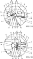
- FIG. 3A is a partial enlarged view of FIG. 1
- FIG. 3B is a partial enlarged view of FIG. 2 .
- the hydraulic rotating machine functions as a piston pump capable of discharging a hydraulic oil as a working fluid by rotating a shaft 1 and reciprocating a piston 5 by an power from the outside.
- the hydraulic rotating machine also functions as a piston motor capable of outputting a rotational driving force by reciprocating the piston 5 and rotating the shaft 1 by the fluid pressure of the hydraulic oil supplied from the outside.
- the hydraulic rotating machine may function only as the piston pump, or may function only as the piston motor.
- the hydraulic rotating machine is used as a swash plate type piston pump.
- the hydraulic rotating machine is referred to as a "piston pump 100".
- the piston pump 100 is used as a hydraulic supply source for supplying hydraulic oil to an actuator such as a hydraulic cylinder (not shown).
- the piston pump 100 includes a shaft 1 which is rotated by a power source such as an engine (not shown), a cylinder block 2 which is connected to the shaft 1 and rotates together with the shaft 1, and a case 3 which houses the cylinder block 2, as shown in FIG. 1 .
- a direction along a rotation center axis O1 of the cylinder block 2 i.e. a central axis of the shaft 1
- a circumferential direction around the rotation center axis O1 of the cylinder block 2 is referred to as a circumferential direction.
- the case 3 includes a bottomed cylindrical case body 3a whose one end opens, and a cover 3b that closes the open end of the case body 3a.
- An inside of the case 3 communicates with a tank (not shown) through a drain passage (not shown).
- the cover 3b is provided with a through hole 3c through which the shaft 1 penetrates.
- One end 1a of the shaft 1 is rotatably supported by the through hole 3c of the cover 3b via a bearing 4a.
- a power source such as an engine (not shown) is connected to the end 1a of the shaft 1 protruding from the case 3 to the outside.
- the bottom of the case body 3a is provided with a shaft housing portion 3d that houses the other end 1b of the shaft 1.
- the end 1b of the shaft 1 is rotatably supported by the shaft housing portion 3d of the case body 3a via a bearing 4b.
- the bottom of the case body 3a may be provided with the shaft housing portion 3d as a through hole through which the shaft 1 penetrates, and a rotary shaft of other hydraulic pump such as a gear pump (not shown) may be connected to the end 1b of the shaft 1 protruding from the case 3 to the outside.
- the cylinder block 2 is provided with a through hole 2a through which the shaft 1 penetrates.
- the through hole 2a of the cylinder block 2 is splined to the shaft 1.
- the cylinder block 2 rotates with the rotation of the shaft 1.
- the cylinder block 2 is provided with a plurality of cylinders 2b which open at one end of the cylinder block 2.
- the cylinders 2b are formed in parallel with the shaft 1.
- the plurality of cylinders 2b are formed with a predetermined interval in the circumferential direction of the cylinder block 2.
- a cylindrical piston 5 is reciprocatively inserted into the cylinder 2b, and a volume chamber 6 is formed by the cylinder 2b and the piston 5.
- the distal end of the piston 5 protrudes from a opening of the cylinder 2b.
- a spherical seat 5a is formed at the distal end of the piston 5, the spherical seat 5a is rotatably connected to a shoe 7 described later.
- the piston pump 100 further includes a swash plate 8 that reciprocates the piston 5 as the cylinder block 2 rotates, a shoe 7 that is in sliding contact with a sliding contact surface 8a formed on the front surface (a surface on the left side shown in the drawing) of the swash plate 8, and a valve plate 9 that is provided between the cylinder block 2 and the bottom portion of the case body 3a.
- the swash plate 8 is swingably supported by the case 3 via a tilt bearing 11.
- a stroke of the piston 5 with respect to the cylinder 2b is changed by changing a tilt angle of the swash plate 8.
- the pump capacity (displacement volume) which is a discharge amount of the hydraulic oil per rotation of the piston pump 100 is changed.
- the pump capacity becomes a minimum value when the tilt angle of the swash plate 8 is a minimum value.
- the pump capacity increases as the tilt angle of the swash plate 8 increases and becomes a maximum value when the tilt angle of the swash plate 8 is a maximum value.
- the tilt angle of the swash plate 8 is controlled by a tilt control device 10 described later.
- the valve plate 9 is a member which a base end surface of the cylinder block 2 is in sliding contact with.
- the valve plate 9 is fixed to the bottom of the case body 3a.
- a suction port and a discharge port are formed in the valve plate 9.
- the suction port connects a suction passage formed on the case body 3a and the volume chamber 6.
- the discharge port connects a discharge passage formed on the case body 3a and the volume chamber 6.
- the tilt control device 10 includes a large-diameter piston 23 as a tilt control piston for controlling the tilt angle of the swash plate 8, and a pressure chamber 28 that the large-diameter piston 23 faces.
- the case body 3a is provided with a housing recess 31 in which the large-diameter piston 23 is reciprocally accommodated.
- the pressure chamber 28 is formed by the housing recess 31 and the large-diameter piston 23.
- the large-diameter piston 23 is disposed so as to face the front surface of the swash plate 8 (the surface on the left side shown in the drawing).
- the large-diameter piston 23 biases the swash plate 8 in a direction in which the tilt angle decreases by the pressure of the pressure chamber 28.
- the tilt control device 10 further includes a stopper 40 that defines a minimum value (a minimum tilt angle) of the tilt angle of the swash plate 8, a small-diameter piston 70 as a tilt control piston that controls the tilt angle of the swash plate 8, and a pressure chamber 29 that the small-diameter piston 70 faces.
- a mounting hole 32 is formed in the cover 3b.
- the the stopper 40 is mounted to the mounting hole 32.
- the stopper 40 has a through hole.
- the inner peripheral surface of the through hole is a sliding surface 43 for slidably supporting the small-diameter piston 70.
- the pressure chamber 29 is formed by the mounting hole 32, the stopper 40, and the small-diameter piston 70.
- the small-diameter piston 70 is disposed so as to face the back surface of the swash plate 8 (a surface of the right side shown in the drawing).
- the small-diameter piston 70 biases the swash plate 8 in a direction in which the tilt angle increases by the pressure of the pressure chamber 29.
- the large-diameter piston 23 and the small-diameter piston 70 are disposed to face each other across the swash plate 8.
- the large-diameter piston 23 and the small-diameter piston 70 are arranged so as to be concentric.
- the pressure chamber 29 is connected to the discharge passage (not shown) of the piston pump 100. Therefore, the discharge pressure P1 (self-pressure) of the piston pump 100 is always guided to the pressure chamber 29 through the discharge passage (not shown).
- the tilt control device 10 further includes a control pressure adjusting device 50 for adjusting the pressure (Hereinafter, referred to control pressure Pc) of the pressure chamber 28.
- the control pressure adjusting device 50 adjusts the control pressure Pc in accordance with the discharge pressure P1 of the piston pump 100 to control an output of the piston pump 100.
- the control pressure adjusting device 50 includes a control pressure adjusting spool 52 for adjusting the control pressure Pc, a sleeve 51 for axially movably accommodating the control pressure adjusting spool 52, a cylindrical feedback pin 55 that abuts the swash plate 8, and springs 53a and 53b as biasing members for biasing the feedback pin 55 toward the swash plate 8 and for biasing the control pressure adjusting spool 52 in a direction for switching the control pressure adjusting spool 52 to a tank communication position described later.
- the tilt angle of the swash plate 8 is adjusted by a balance of a moment around a swing center axis 02.
- the direction of the moment of the force transmitted from the feedback pin 55 to the swash plate 8 by the elastic force of the springs 53a and 53b is the same as a direction of the moment of the force transmitted from the small-diameter piston 70 to the swash plate 8 by the pressure of the pressure chamber 29, and is opposite to a direction of the moment of the force transmitted from the large-diameter piston 23 to the swash plate 8 by the pressure of the pressure chamber 28.
- the control pressure adjusting device 50 has a pump port 50p communicating with the discharge passage (not shown) of the piston pump 100, a tank port 50t communicating with a tank (not shown), and a control pressure port 50c communicating with the pressure chamber 28.
- the control pressure adjusting spool 52 has a pump communication position and a tank communication position. In the pump communication position, the pump port 50p and the control pressure port 50c communicate with each other and a communication between the tank port 50t and the control pressure port 50c is blocked. In the tank communication position, the tank port 50t and the control pressure port 50c communicate with each other and a communication between the pump port 50p and the control pressure port 50c is blocked.
- the control pressure adjusting device 50 may include a port which the discharge pressure (external pump pressure) of another pump driven by the engine (not shown) together with the piston pump 100, and/or the signal pressure (external signal pressure) from the outside is guided.
- the control characteristics of the swash plate 8 can be adjusted by the external pump pressure and/or the external signal pressure.
- the piston pump 100 is controlled by the tilt control device 10 so that the pump capacity decreases when the discharge pressure P1 increases and the pump capacity increases when the discharge pressure P1 decreases.
- the operation of the piston pump 100 when the discharge pressure P1 increases to the predetermined pressure will be described.
- the pump capacity is maintained at a maximum state (see FIG. 1 ).
- the control pressure adjusting spool 52 moves to the right in the drawing and is switched to the pump communication position.
- the control pressure adjusting spool 52 is switched to the pump communication position, the pressure in the pressure chamber 29 (the control pressure Pc) increases and the large-diameter piston 23 presses the swash plate 8, so that the tilt angle of the swash plate 8 decreases.
- the control pressure adjusting spool 52 is switched to the pump communication position again, and the tilt angle of the swash plate 8 decreases.
- the increase and decrease of the tilt angle of the swash plate 8 is repeated.
- the tilt of the swash plate 8 is stopped, and the tilt angle of the swash plate 8 becomes a tilt angle in accordance with the discharge pressure P1.
- a horsepower control is performed in which the pump capacity is controlled in accordance with the discharge pressure P1 so that an output of the piston pump 100 is kept constant.
- the tilt angle is controlled so that the pump capacity decreases.
- the members constituting the piston pump may wear due to sliding, and thereby, backlash between the members occur.
- the backlash between the members may cause deterioration of the pump performance, such as unstable discharge rate of the piston pump. Therefore, in order to maintain the pump performance over a long period, it is effective to suppress the wear of the member.
- As a method for suppressing the wear of the member it is effective to perform surface treatment such as heat treatment on the member.
- the cover 3b does not directly slidably support the small-diameter piston 70 which is a sliding component, but a small component mounted to the cover 3b slidably supports the small-diameter piston 70.
- the stopper 40 which defines the minimum tilt angle of the swash plate 8 is adopted as the small component for slidably supporting the small-diameter piston 70. That is, the stopper 40 according to the present embodiment has both a function of defining the minimum tilt angle of the swash plate 8 and a function of slidably supporting the small-diameter piston 70.
- the swash plate 8 includes a swash plate body 91 formed by casting or the like, a piston receiving member 60 disposed between the swash plate body 91 and the small-diameter piston 70, a first support member 86 disposed between the swash plate body 91 and the large-diameter piston 23, and a second support member 87 disposed between the swash plate body 91 and the feedback pin 55.
- the stopper 40 has a mounting portion 41 which is mounted to the mounting hole 32 of the cover 3b, and an abutting portion 42 which abuts the piston receiving member 60 which is attached to the swash plate 8.
- a male screw is formed on the outer periphery of the mounting portion 41. The male screw is screwed onto a female screw which is formed on the inner periphery of the mounting hole 32.
- a state in which the large-diameter piston 23 abuts against the bottom of the housing recess 31 and the protruding length of the small-diameter piston 70 protruding from the stopper 40 toward the swash plate 8 is maximized is a state in which the tilt angle of the swash plate 8 is maximized. From this state, the tilt angle of the swash plate 8 is decreased, and as shown in FIGS. 2 and 3B , when the piston receiving member 60 attached to the swash plate 8 abuts the distal end surface of the abutting portion 42 of the stopper 40, it is restricted that the tilt angle of the swash plate 8 is further decreased.
- a state in which the piston receiving member 60 attached to the swash plate 8 abuts the distal end surface of the abutting portion 42 and the small-diameter piston 70 is housed in the stopper 40 is a state in which the tilt angle of the swash plate 8 is minimized.
- the small-diameter piston 70 accommodated in the through hole of the stopper 40 has a cylindrical piston body 71 and a piston shoe 72 provided at the distal end of the piston body 71.
- the piston shoe 72 has a disc-shaped base 73 and a spherical seat 74 which is fixed to the base 73.
- the base 73 and the spherical seat 74 may be formed as a single component by integral molding.
- a receiving portion 71a for receiving the spherical seat 74 of the piston shoe 72 is formed at the distal end of the piston body 71.
- the inner surface of the receiving portion 71a is formed in a spherical shape so as to be in sliding contact with the outer surface of the spherical seat 74. This allows the piston shoe 72 to be displaced in any direction relative to the piston body 71.
- the piston receiving member 60 is attached to a step portion 81 formed on the back surface of the swash plate 8.
- a back-side recess 82 as a recess portion is formed on the step portion 81.
- the piston receiving member 60 has a cylindrical press-fit portion 61 which is press-fitted and fixed to the back-side recess 82, and a disc-shaped receiving portion 62 which abuts the step portion 81.
- a sliding contact surface 63 is formed on the receiving portion 62.
- the small-diameter piston 70 is in sliding contact with the sliding contact surface 63.
- the sliding contact surface 63 of the receiving portion 62 is in sliding contact with the base 73 of the piston shoe 72.
- the piston shoe 72 is held in a state sandwiched between the receiving portion 62 of the piston receiving member 60 and the receiving portion 71a of the piston body 71. Therefore, in the present embodiment, in a case where the tilt angle is in the minimum state, when the control pressure Pc is lowered and the small-diameter piston 70 is pushed toward the swash plate 8 by the discharge pressure P1 of the piston pump 100, the piston shoe 72 provided at the distal end of the small-diameter piston 70 presses the swash plate body 91 via the piston receiving member 60. Thus, the tilt angle of the swash plate 8 increases.
- the stopper 40 is smaller in size and simpler in shape than the cover 3b, it is possible to easily perform surface treatment such as heat treatment. Therefore, it is possible to easily improve the hardness of the sliding surface 43 on which the outer peripheral surface of the small-diameter piston 70 slides. Thus, backlash and/or prizing between the small-diameter piston 70 and the sliding surface 43 are prevented over a long period, and thereby, it is possible to maintain good sliding property. As a result, it is possible to prevent the control of the swash plate 8 from becoming unstable due to the backlash or the like, and to maintain good pump performance for a long period.
- the present embodiment by improving the hardness of the sliding surface 43, it can be set shorter axial length of the piston body 71. Thus, it is possible to reduce the frictional resistance between the sliding surface 43 and the piston body 71. As a result, the hysteresis of the tilt angle of the swash plate 8 between increasing the tilt angle and decreasing the tilt angle, which is set in accordance with the control pressure Pc, can be reduced.
- the piston receiving member 60 is smaller in size and simpler in shape than the swash plate 8, it is possible to easily perform surface treatment such as heat treatment. Therefore, it is possible to easily improve the hardness of the sliding contact surface 63 which the piston shoe 72 of the small-diameter piston 70 is in sliding contact with. Thus, it is possible to prevent wear of the sliding contact surface 63.
- the position of the force transmitted from each of the small-diameter piston 70, the large-diameter piston 23, and the feedback pin 55 may change, and thereby, the performance of the piston pump 100 may change.
- the small-diameter piston 70 is in sliding contact with the piston receiving member 60 attached to the swash plate 8, the wear of the swash plate 8 can be prevented. As a result, the performance of the piston pump 100 can be well maintained for a long period.
- a front-side first recess 83 and a front-side second recess 84 as recesses are formed on the front surface of the swash plate 8.
- the cylindrical or spherical first support member 86 is accommodated in the front-side first recess 83.
- the cylindrical or spherical second support member 87 is accommodated in the front-side second recess 84.
- the first support member 86 is held in a state sandwiched between the front-side first recess 83 and the large-diameter piston 23. That is, the large-diameter piston 23 transmits a force to the swash plate 8 via the first support member 86.
- the second support member 87 is held in a state sandwiched between the front-side second recess 84 and the feedback pin 55. That is, the feedback pin 55 transmits a force to the swash plate 8 via the second support member 87.
- first support member 86 is smaller in size and simpler in shape than the swash plate 8
- surface treatment such as heat treatment can be easily performed. Therefore, it is possible to easily improve the hardness of a sliding contact surface 86a which the large-diameter piston 23 is in sliding contact with.
- second support member 87 is smaller in size and simpler in shape than the swash plate 8, surface treatment such as heat treatment can be easily performed. Therefore, it is possible to easily improve the hardness of a sliding contact surface 87a which the feedback pin 55 is in sliding contact with.
- the large-diameter piston 23 biases the swash plate 8 against the force transmitted from the small-diameter piston 70 to the swash plate 8 and the force transmitted from the feedback pin 55 to the swash plate 8. Therefore, the force acting on the front-side first recess 83 of the swash plate 8 from the first support member 86 is larger than the force acting on the front-side second recess 84 of the swash plate 8 from the second support member 87.
- a curved surface 83a contacting the outer peripheral surface of the first support member 86 is formed at the bottom of the front-side first recess 83.
- the load applied from the first support member 86 to the bottom of the front-side first recess 83 can be dispersed, and thereby, wear of the front-side first recess 83 can be effectively prevented.
- the bottom of the front-side first recess 83 and the bottom of the back-side recess 82 are communicated through a communication passage 89. Therefore, when the press-fit portion 61 of the piston receiving member 60 is press-fitted to the back-side recess 82, a gas between the back-side recess 82 and the press-fit portion 61 is discharged to the front-side first recess 83 through the communication passage 89. Therefore, the piston receiving member 60 can be appropriately and easily attached to the swash plate 8.
- each member is disposed so that a contact portion C1 between the small-diameter piston 70 and the swash plate 8, a contact portion C2 between the large-diameter piston 23 and the swash plate 8, and a contact portion C3 between the feedback pin 55 and the swash plate 8 are positioned on the same plane.
- the effect of this configuration will be described in comparison with the comparative example.
- the contact portion C2 is disposed on a virtual plane which is perpendicular to the swing center axis 02 of the swash plate 8 and includes the rotation center axis O1 of the cylinder block 2. Further, in the comparative example of the present embodiment, the contact portion C1 is disposed at a position separated from the virtual plane by a predetermined distance on one side. The contact portion C3 is disposed at a position separated from the virtual plane by a predetermined distance on the other side (the side opposite to the contact portion C1). For example, the contact portion C1 and the contact portion C3 are disposed so as to be plane symmetric with respect to the virtual plane.
- the swash plate 8 is inclined in a direction different from the swing direction.
- the swash plate 8 may be inclined around an axis orthogonal to the rotation center axis O1 and the swing center axis 02.
- the contact portion C1, the contact portion C2, and the contact portion C3 are disposed on the same plane, it is possible to prevent the swash plate 8 from inclining in a direction different from the swing direction. As a result, the hysteresis of the tilt angle of the swash plate 8 between increasing the tilt angle and decreasing the tilt angle, which is set in accordance with the control pressure Pc, can be reduced. Further, in the present embodiment, since the small-diameter piston 70 and the large-diameter piston 23 sandwich the swash plate 8 on the same straight line, vibration of the swash plate 8 can be suppressed as compared with the comparative example.
- the tilt control of the swash plate 8 can be performed more stably. As a result, the discharge rate of the piston pump 100 is more stable.
- the small-diameter piston 70 presses the back surface of the swash plate 8 by the pressure of the pressure chamber 29. Therefore, since the load applied to the tilt bearing 11 can be reduced as compared with a case where the small-diameter piston 70 presses the front surface of the swash plate 8, damage to the tilt bearing 11 can be effectively prevented.
- a small-diameter piston 70 as the tilt control piston is slidably supported by the stopper 40 mounted to the cover 3b constituting the case 3. Since the stopper 40 is smaller in size than the cover 3b, it is possible to easily perform surface treatment such as heat treatment. Therefore, it is possible to easily improve the wear resistance of the sliding surface 43 which the small-diameter piston 70 slides. Thus, since it is possible to maintain good slidability of the small-diameter piston 70 for a long period, it is possible to maintain good performance of the piston pump 100 for a long period.
- the contact portion C1 may be disposed on an virtual plane orthogonal to the rotation center axis O1 and the swing center axis 02
- the contact portion C1 and the contact portion C3 may be disposed so as to be plane symmetric with respect to the virtual plane.
- the hydraulic rotating machine (the piston pump 100 and piston motor) includes the case 3, the cylinder block 2 housed in the case 3 and having a plurality of cylinders 2b, the piston 5 reciprocatively inserted into the cylinder 2b, the swash plate 8 configured to reciprocate the piston 5 as the cylinder block 2 rotates, the tilt control piston (small-diameter piston 70) configured to biase the swash plate 8 and control the tilt angle of the swash plate 8, and the stopper 40 which is mounted to the case 3 and configured to define the minimum tilt angle of the swash plate 8.
- the stopper 40 has a sliding surface 43 for slidably supporting the tilt control piston (small-diameter piston 70).
- the tilt control piston small-diameter piston 70
- the stopper 40 Since the stopper 40 is smaller in size than the case 3, it is possible to easily perform surface treatment such as heat treatment. Therefore, it is possible to easily improve the wear resistance of the sliding surface 43 which the tilt control piston (small-diameter piston 70) slides.
- the swash plate 8 includes the swash plate body 91 and the piston receiving member 60 attached to the swash plate body 91 and having the sliding contact surface 63 which the tilt control piston (the small-diameter piston 70) is in sliding contact with.
- the tilt control piston (the small-diameter piston 70) is in sliding contact with the piston receiving member 60 attached to the swash plate body 91. Since the piston receiving member 60 is smaller in size than the swash plate body 91, it is possible to easily perform surface treatment such as heat treatment. Therefore, it is possible to easily improve the wear resistance of the sliding contact surface 63 which the tilt control piston (small-diameter piston 70) is in sliding contact with.
Landscapes
- Engineering & Computer Science (AREA)
- Mechanical Engineering (AREA)
- General Engineering & Computer Science (AREA)
- Chemical & Material Sciences (AREA)
- Combustion & Propulsion (AREA)
- Reciprocating Pumps (AREA)
- Hydraulic Motors (AREA)
Abstract
Description
- The present invention relates to a hydraulic srotating machine.
- There is a hydraulic rotating machine which includes a swash plate which is provided in a casing so as to be tiltable, and a tilt control piston which controls the tilt angle of the swash plate (see JPH8-200209A). In the hydraulic rotating machine described in JPH8-200209A, a cylinder hole is formed in the casing , the tilt control piston is slidably inserted into the cylinder hole.
- In the hydraulic rotating machine described in JPH8-200209A, since the tilt control piston slides in the cylinder hole, the inner peripheral surface of the cylinder hole is worn, thereby there is a possibility that the performance of a pump is deteriorated. To suppress wear of the inner peripheral surface of the cylinder hole, it is effective to perform a surface treatment such as heat treatment as a method of improving the hardness of the inner peripheral surface of the cylinder hole. However, it is not easy to perform the surface treatment such as heat treatment to the inner peripheral surface of the cylinder hole formed in the casing.
- The present invention aims to easily improve a wear resistance of a sliding surface that a tilt control piston slides.
- According to one aspect of the present invention, a hydraulic rotating machine includes: a case; a cylinder block housed in the case and having a plurality of cylinders, a piston reciprocatively inserted into the cylinder; a swash plate configured to reciprocate the piston as the cylinder block rotates, a tilt control piston configured to biase the swash plate and control a tilt angle of the swash plate; and a stopper mounted to the case, the stopper being configured to define a minimum tilt angle of the swash plate. The stopper has a sliding surface for slidably supporting the tilt control piston.
-
-
FIG. 1 is a cross-sectional view of a hydraulic rotating machine according to an embodiment of the present invention, showing a state in which a tilt angle is maximum. -
FIG. 2 is a cross-sectional view of the hydraulic rotating machine according to the embodiment of the present invention, showing a state in which the tilt angle is minimum. -
FIG. 3A is a partial enlarged view ofFIG. 1 . -
FIG. 3b is a partial enlarged view ofFIG. 2 . - A hydraulic rotating machine according to an embodiment of the present invention will be described with reference to the drawings.
FIGS. 1 and2 are a cross-sectional view of the hydraulic rotating machine.FIG. 1 shows a state in which a tilt angle is maximum,FIG. 2 shows a state in which the tilt angle is minimum.FIG. 3A is a partial enlarged view ofFIG. 1 , andFIG. 3B is a partial enlarged view ofFIG. 2 . - The hydraulic rotating machine functions as a piston pump capable of discharging a hydraulic oil as a working fluid by rotating a shaft 1 and reciprocating a
piston 5 by an power from the outside. The hydraulic rotating machine also functions as a piston motor capable of outputting a rotational driving force by reciprocating thepiston 5 and rotating the shaft 1 by the fluid pressure of the hydraulic oil supplied from the outside. Incidentally, the hydraulic rotating machine may function only as the piston pump, or may function only as the piston motor. - In the present embodiment, a case where the hydraulic rotating machine is used as a swash plate type piston pump will be exemplified. Hereinafter, the hydraulic rotating machine is referred to as a "
piston pump 100". - As shown in
FIGS. 1 and2 , thepiston pump 100 is used as a hydraulic supply source for supplying hydraulic oil to an actuator such as a hydraulic cylinder (not shown). Thepiston pump 100 includes a shaft 1 which is rotated by a power source such as an engine (not shown), acylinder block 2 which is connected to the shaft 1 and rotates together with the shaft 1, and acase 3 which houses thecylinder block 2, as shown inFIG. 1 . Hereinafter, a direction along a rotation center axis O1 of the cylinder block 2 (i.e. a central axis of the shaft 1) is referred to as an axial direction, a circumferential direction around the rotation center axis O1 of thecylinder block 2 is referred to as a circumferential direction. - The
case 3 includes a bottomedcylindrical case body 3a whose one end opens, and acover 3b that closes the open end of thecase body 3a. An inside of thecase 3 communicates with a tank (not shown) through a drain passage (not shown). - The
cover 3b is provided with athrough hole 3c through which the shaft 1 penetrates. Oneend 1a of the shaft 1 is rotatably supported by thethrough hole 3c of thecover 3b via abearing 4a. A power source such as an engine (not shown) is connected to theend 1a of the shaft 1 protruding from thecase 3 to the outside. - The bottom of the
case body 3a is provided with ashaft housing portion 3d that houses theother end 1b of the shaft 1. Theend 1b of the shaft 1 is rotatably supported by theshaft housing portion 3d of thecase body 3a via abearing 4b. Incidentally, the bottom of thecase body 3a may be provided with theshaft housing portion 3d as a through hole through which the shaft 1 penetrates, and a rotary shaft of other hydraulic pump such as a gear pump (not shown) may be connected to theend 1b of the shaft 1 protruding from thecase 3 to the outside. - The
cylinder block 2 is provided with athrough hole 2a through which the shaft 1 penetrates. The throughhole 2a of thecylinder block 2 is splined to the shaft 1. Thus, thecylinder block 2 rotates with the rotation of the shaft 1. - The
cylinder block 2 is provided with a plurality ofcylinders 2b which open at one end of thecylinder block 2. Thecylinders 2b are formed in parallel with the shaft 1. The plurality ofcylinders 2b are formed with a predetermined interval in the circumferential direction of thecylinder block 2. Acylindrical piston 5 is reciprocatively inserted into thecylinder 2b, and avolume chamber 6 is formed by thecylinder 2b and thepiston 5. The distal end of thepiston 5 protrudes from a opening of thecylinder 2b. Aspherical seat 5a is formed at the distal end of thepiston 5, thespherical seat 5a is rotatably connected to ashoe 7 described later. - The
piston pump 100 further includes aswash plate 8 that reciprocates thepiston 5 as thecylinder block 2 rotates, ashoe 7 that is in sliding contact with a slidingcontact surface 8a formed on the front surface (a surface on the left side shown in the drawing) of theswash plate 8, and avalve plate 9 that is provided between thecylinder block 2 and the bottom portion of thecase body 3a. - The
swash plate 8 is swingably supported by thecase 3 via a tilt bearing 11. In thepiston pump 100, a stroke of thepiston 5 with respect to thecylinder 2b is changed by changing a tilt angle of theswash plate 8. Thus, the pump capacity (displacement volume) which is a discharge amount of the hydraulic oil per rotation of thepiston pump 100 is changed. The pump capacity becomes a minimum value when the tilt angle of theswash plate 8 is a minimum value. The pump capacity increases as the tilt angle of theswash plate 8 increases and becomes a maximum value when the tilt angle of theswash plate 8 is a maximum value. The tilt angle of theswash plate 8 is controlled by atilt control device 10 described later. - The
valve plate 9 is a member which a base end surface of thecylinder block 2 is in sliding contact with. Thevalve plate 9 is fixed to the bottom of thecase body 3a. Although not shown, a suction port and a discharge port are formed in thevalve plate 9. The suction port connects a suction passage formed on thecase body 3a and thevolume chamber 6. The discharge port connects a discharge passage formed on thecase body 3a and thevolume chamber 6. - The
tilt control device 10 includes a large-diameter piston 23 as a tilt control piston for controlling the tilt angle of theswash plate 8, and apressure chamber 28 that the large-diameter piston 23 faces. Thecase body 3a is provided with a housing recess 31 in which the large-diameter piston 23 is reciprocally accommodated. Thepressure chamber 28 is formed by thehousing recess 31 and the large-diameter piston 23. The large-diameter piston 23 is disposed so as to face the front surface of the swash plate 8 (the surface on the left side shown in the drawing). The large-diameter piston 23 biases theswash plate 8 in a direction in which the tilt angle decreases by the pressure of thepressure chamber 28. - The
tilt control device 10 further includes astopper 40 that defines a minimum value (a minimum tilt angle) of the tilt angle of theswash plate 8, a small-diameter piston 70 as a tilt control piston that controls the tilt angle of theswash plate 8, and apressure chamber 29 that the small-diameter piston 70 faces. A mountinghole 32 is formed in thecover 3b. The thestopper 40 is mounted to the mountinghole 32. Thestopper 40 has a through hole. The inner peripheral surface of the through hole is a slidingsurface 43 for slidably supporting the small-diameter piston 70. Thepressure chamber 29 is formed by the mountinghole 32, thestopper 40, and the small-diameter piston 70. The small-diameter piston 70 is disposed so as to face the back surface of the swash plate 8 (a surface of the right side shown in the drawing). The small-diameter piston 70 biases theswash plate 8 in a direction in which the tilt angle increases by the pressure of thepressure chamber 29. - The large-
diameter piston 23 and the small-diameter piston 70 are disposed to face each other across theswash plate 8. In the present embodiment, the large-diameter piston 23 and the small-diameter piston 70 are arranged so as to be concentric. - The
pressure chamber 29 is connected to the discharge passage (not shown) of thepiston pump 100. Therefore, the discharge pressure P1 (self-pressure) of thepiston pump 100 is always guided to thepressure chamber 29 through the discharge passage (not shown). - The
tilt control device 10 further includes a controlpressure adjusting device 50 for adjusting the pressure (Hereinafter, referred to control pressure Pc) of thepressure chamber 28. The controlpressure adjusting device 50 adjusts the control pressure Pc in accordance with the discharge pressure P1 of thepiston pump 100 to control an output of thepiston pump 100. - The control
pressure adjusting device 50 includes a controlpressure adjusting spool 52 for adjusting the control pressure Pc, asleeve 51 for axially movably accommodating the controlpressure adjusting spool 52, acylindrical feedback pin 55 that abuts theswash plate 8, and springs 53a and 53b as biasing members for biasing thefeedback pin 55 toward theswash plate 8 and for biasing the controlpressure adjusting spool 52 in a direction for switching the controlpressure adjusting spool 52 to a tank communication position described later. - The tilt angle of the
swash plate 8 is adjusted by a balance of a moment around aswing center axis 02. The direction of the moment of the force transmitted from thefeedback pin 55 to theswash plate 8 by the elastic force of thesprings diameter piston 70 to theswash plate 8 by the pressure of thepressure chamber 29, and is opposite to a direction of the moment of the force transmitted from the large-diameter piston 23 to theswash plate 8 by the pressure of thepressure chamber 28. - The control
pressure adjusting device 50 has apump port 50p communicating with the discharge passage (not shown) of thepiston pump 100, atank port 50t communicating with a tank (not shown), and acontrol pressure port 50c communicating with thepressure chamber 28. - The control
pressure adjusting spool 52 has a pump communication position and a tank communication position. In the pump communication position, thepump port 50p and thecontrol pressure port 50c communicate with each other and a communication between thetank port 50t and thecontrol pressure port 50c is blocked. In the tank communication position, thetank port 50t and thecontrol pressure port 50c communicate with each other and a communication between thepump port 50p and thecontrol pressure port 50c is blocked. - When the control
pressure adjusting spool 52 is switched to the pump communication position, the hydraulic oil discharged from thepiston pump 100 is guided to thepressure chamber 28, and the control pressure Pc increases. When the control pressure Pc becomes higher than the predetermined pressure, theswash plate 8 tilts in a direction in which the tilt angle of theswash plate 8 decreases, and the pump capacity decreases. - When the control
pressure adjusting spool 52 is switched to the tank communication position, the hydraulic oil of thepressure chamber 28 is discharged to the tank (not shown), and the control pressure Pc decreases. When the control pressure Pc becomes lower than the predetermined pressure, theswash plate 8 tilts in a direction in which the tilt angle of theswash plate 8 increases, and the pump capacity increases. - The control
pressure adjusting device 50 may include a port which the discharge pressure (external pump pressure) of another pump driven by the engine (not shown) together with thepiston pump 100, and/or the signal pressure (external signal pressure) from the outside is guided. In this case, the control characteristics of theswash plate 8 can be adjusted by the external pump pressure and/or the external signal pressure. - The
piston pump 100 is controlled by thetilt control device 10 so that the pump capacity decreases when the discharge pressure P1 increases and the pump capacity increases when the discharge pressure P1 decreases. Hereinafter, as an example of the operation of thepiston pump 100, the operation of thepiston pump 100 when the discharge pressure P1 increases to the predetermined pressure will be described. - If the discharge pressure P1 of the
piston pump 100 is less than a predetermined value, the pump capacity is maintained at a maximum state (seeFIG. 1 ). When the discharge pressure P1 increases to a predetermined pressure equal to or higher than the predetermined value, the controlpressure adjusting spool 52 moves to the right in the drawing and is switched to the pump communication position. When the controlpressure adjusting spool 52 is switched to the pump communication position, the pressure in the pressure chamber 29 (the control pressure Pc) increases and the large-diameter piston 23 presses theswash plate 8, so that the tilt angle of theswash plate 8 decreases. - When the tilt angle of the
swash plate 8 decreases as the control pressure Pc increases, thefeedback pin 55 is pushed leftward in the drawing by theswash plate 8. When thefeedback pin 55 is pushed to the leftward, the controlpressure adjusting spool 52 is pushed back to the leftward by being biased by thefeedback pin 55 via thesprings pressure adjusting spool 52 is switched to the tank communicating position, the pressure of thepressure chamber 28 decreases. When the control pressure Pc decreases, the tilt angle of theswash plate 8 increases because theswash plate 8 is pressed by the small-diameter piston 70. - When the tilt angle of the
swash plate 8 increases as the control pressure Pc decreases, the controlpressure adjusting spool 52 is switched to the pump communication position again, and the tilt angle of theswash plate 8 decreases. Thus, in thetilt control device 10, the increase and decrease of the tilt angle of theswash plate 8 is repeated. When the moment of the force transmitted from the small-diameter piston 70 and thefeedback pin 55 to theswash plate 8 and the moment of the force transmitted from the large-diameter piston 23 to theswash plate 8 are balanced, the tilt of theswash plate 8 is stopped, and the tilt angle of theswash plate 8 becomes a tilt angle in accordance with the discharge pressure P1. - Thus, in the present embodiment, a horsepower control is performed in which the pump capacity is controlled in accordance with the discharge pressure P1 so that an output of the
piston pump 100 is kept constant. In the horsepower control, when the discharge pressure P1 of thepiston pump 100 increases, the tilt angle is controlled so that the pump capacity decreases. Thus, it is possible to prevent an overload of the engine (not shown) as the power source of thepiston pump 100. - In general, in a piston pump, the members constituting the piston pump may wear due to sliding, and thereby, backlash between the members occur. The backlash between the members may cause deterioration of the pump performance, such as unstable discharge rate of the piston pump. Therefore, in order to maintain the pump performance over a long period, it is effective to suppress the wear of the member. As a method for suppressing the wear of the member, it is effective to perform surface treatment such as heat treatment on the member. However, depending on size and shape of the member, it may not be easy to perform the surface treatment. For example, since the
case body 3a and thecover 3b constituting thecase 3 are large and complicated shape compared to other components, it is particularly difficult to perform the surface treatment to thecase body 3a and thecover 3b. - Therefore, in the present embodiment, the
cover 3b does not directly slidably support the small-diameter piston 70 which is a sliding component, but a small component mounted to thecover 3b slidably supports the small-diameter piston 70. In addition, thestopper 40 which defines the minimum tilt angle of theswash plate 8 is adopted as the small component for slidably supporting the small-diameter piston 70. That is, thestopper 40 according to the present embodiment has both a function of defining the minimum tilt angle of theswash plate 8 and a function of slidably supporting the small-diameter piston 70. Thus, as compared with a case of providing individually parts having respective functions, it is possible to reduce the number of parts. - The
swash plate 8 includes aswash plate body 91 formed by casting or the like, apiston receiving member 60 disposed between theswash plate body 91 and the small-diameter piston 70, afirst support member 86 disposed between theswash plate body 91 and the large-diameter piston 23, and asecond support member 87 disposed between theswash plate body 91 and thefeedback pin 55. - The
stopper 40 has a mountingportion 41 which is mounted to the mountinghole 32 of thecover 3b, and an abuttingportion 42 which abuts thepiston receiving member 60 which is attached to theswash plate 8. A male screw is formed on the outer periphery of the mountingportion 41. The male screw is screwed onto a female screw which is formed on the inner periphery of the mountinghole 32. - As shown in
FIGS. 1 and3A , a state in which the large-diameter piston 23 abuts against the bottom of thehousing recess 31 and the protruding length of the small-diameter piston 70 protruding from thestopper 40 toward theswash plate 8 is maximized is a state in which the tilt angle of theswash plate 8 is maximized. From this state, the tilt angle of theswash plate 8 is decreased, and as shown inFIGS. 2 and3B , when thepiston receiving member 60 attached to theswash plate 8 abuts the distal end surface of the abuttingportion 42 of thestopper 40, it is restricted that the tilt angle of theswash plate 8 is further decreased. A state in which thepiston receiving member 60 attached to theswash plate 8 abuts the distal end surface of the abuttingportion 42 and the small-diameter piston 70 is housed in thestopper 40 is a state in which the tilt angle of theswash plate 8 is minimized. - As shown in
FIGS. 3A and 3B , the small-diameter piston 70 accommodated in the through hole of thestopper 40 has acylindrical piston body 71 and apiston shoe 72 provided at the distal end of thepiston body 71. Thepiston shoe 72 has a disc-shapedbase 73 and aspherical seat 74 which is fixed to thebase 73. Incidentally, thebase 73 and thespherical seat 74 may be formed as a single component by integral molding. - A receiving
portion 71a for receiving thespherical seat 74 of thepiston shoe 72 is formed at the distal end of thepiston body 71. The inner surface of the receivingportion 71a is formed in a spherical shape so as to be in sliding contact with the outer surface of thespherical seat 74. This allows thepiston shoe 72 to be displaced in any direction relative to thepiston body 71. - The
piston receiving member 60 is attached to astep portion 81 formed on the back surface of theswash plate 8. A back-side recess 82 as a recess portion is formed on thestep portion 81. Thepiston receiving member 60 has a cylindrical press-fit portion 61 which is press-fitted and fixed to the back-side recess 82, and a disc-shaped receivingportion 62 which abuts thestep portion 81. A slidingcontact surface 63 is formed on the receivingportion 62. The small-diameter piston 70 is in sliding contact with the slidingcontact surface 63. - The sliding
contact surface 63 of the receivingportion 62 is in sliding contact with thebase 73 of thepiston shoe 72. Thepiston shoe 72 is held in a state sandwiched between the receivingportion 62 of thepiston receiving member 60 and the receivingportion 71a of thepiston body 71. Therefore, in the present embodiment, in a case where the tilt angle is in the minimum state, when the control pressure Pc is lowered and the small-diameter piston 70 is pushed toward theswash plate 8 by the discharge pressure P1 of thepiston pump 100, thepiston shoe 72 provided at the distal end of the small-diameter piston 70 presses theswash plate body 91 via thepiston receiving member 60. Thus, the tilt angle of theswash plate 8 increases. - Since the
stopper 40 is smaller in size and simpler in shape than thecover 3b, it is possible to easily perform surface treatment such as heat treatment. Therefore, it is possible to easily improve the hardness of the slidingsurface 43 on which the outer peripheral surface of the small-diameter piston 70 slides. Thus, backlash and/or prizing between the small-diameter piston 70 and the slidingsurface 43 are prevented over a long period, and thereby, it is possible to maintain good sliding property. As a result, it is possible to prevent the control of theswash plate 8 from becoming unstable due to the backlash or the like, and to maintain good pump performance for a long period. - Furthermore, in the present embodiment, by improving the hardness of the sliding
surface 43, it can be set shorter axial length of thepiston body 71. Thus, it is possible to reduce the frictional resistance between the slidingsurface 43 and thepiston body 71. As a result, the hysteresis of the tilt angle of theswash plate 8 between increasing the tilt angle and decreasing the tilt angle, which is set in accordance with the control pressure Pc, can be reduced. - Further, since the
piston receiving member 60 is smaller in size and simpler in shape than theswash plate 8, it is possible to easily perform surface treatment such as heat treatment. Therefore, it is possible to easily improve the hardness of the slidingcontact surface 63 which thepiston shoe 72 of the small-diameter piston 70 is in sliding contact with. Thus, it is possible to prevent wear of the slidingcontact surface 63. - When the
swash plate 8 is worn, the position of the force transmitted from each of the small-diameter piston 70, the large-diameter piston 23, and thefeedback pin 55 may change, and thereby, the performance of thepiston pump 100 may change. In the present embodiment, as described above, since the small-diameter piston 70 is in sliding contact with thepiston receiving member 60 attached to theswash plate 8, the wear of theswash plate 8 can be prevented. As a result, the performance of thepiston pump 100 can be well maintained for a long period. - As shown in
FIGS. 1 and2 , a front-sidefirst recess 83 and a front-sidesecond recess 84 as recesses are formed on the front surface of theswash plate 8. The cylindrical or sphericalfirst support member 86 is accommodated in the front-sidefirst recess 83. The cylindrical or sphericalsecond support member 87 is accommodated in the front-sidesecond recess 84. - The
first support member 86 is held in a state sandwiched between the front-sidefirst recess 83 and the large-diameter piston 23. That is, the large-diameter piston 23 transmits a force to theswash plate 8 via thefirst support member 86. Thesecond support member 87 is held in a state sandwiched between the front-sidesecond recess 84 and thefeedback pin 55. That is, thefeedback pin 55 transmits a force to theswash plate 8 via thesecond support member 87. - Since the
first support member 86 is smaller in size and simpler in shape than theswash plate 8, surface treatment such as heat treatment can be easily performed. Therefore, it is possible to easily improve the hardness of a slidingcontact surface 86a which the large-diameter piston 23 is in sliding contact with. Similarly, since thesecond support member 87 is smaller in size and simpler in shape than theswash plate 8, surface treatment such as heat treatment can be easily performed. Therefore, it is possible to easily improve the hardness of a slidingcontact surface 87a which thefeedback pin 55 is in sliding contact with. - Since the large-
diameter piston 23 is in sliding contact with thefirst support member 86 provided on theswash plate 8, wear of theswash plate 8 can be prevented. Further, since thefeedback pin 55 is in sliding contact with thesecond support member 87 provided on theswash plate 8, wear of theswash plate 8 can be prevented. As a result, the performance of thepiston pump 100 can be well maintained for a long period. - The large-
diameter piston 23 biases theswash plate 8 against the force transmitted from the small-diameter piston 70 to theswash plate 8 and the force transmitted from thefeedback pin 55 to theswash plate 8. Therefore, the force acting on the front-sidefirst recess 83 of theswash plate 8 from thefirst support member 86 is larger than the force acting on the front-sidesecond recess 84 of theswash plate 8 from thesecond support member 87. In the present embodiment, as shown inFIGS. 3A and 3B , acurved surface 83a contacting the outer peripheral surface of thefirst support member 86 is formed at the bottom of the front-sidefirst recess 83. Therefore, as compared with a case where thefirst support member 86 and the bottom of the front-sidefirst recess 83 are point contact or line contact with each other, the load applied from thefirst support member 86 to the bottom of the front-sidefirst recess 83 can be dispersed, and thereby, wear of the front-sidefirst recess 83 can be effectively prevented. - The bottom of the front-side
first recess 83 and the bottom of the back-side recess 82 are communicated through acommunication passage 89. Therefore, when the press-fit portion 61 of thepiston receiving member 60 is press-fitted to the back-side recess 82, a gas between the back-side recess 82 and the press-fit portion 61 is discharged to the front-sidefirst recess 83 through thecommunication passage 89. Therefore, thepiston receiving member 60 can be appropriately and easily attached to theswash plate 8. - Further, in the present embodiment, as shown in
FIG. 1 , each member is disposed so that a contact portion C1 between the small-diameter piston 70 and theswash plate 8, a contact portion C2 between the large-diameter piston 23 and theswash plate 8, and a contact portion C3 between thefeedback pin 55 and theswash plate 8 are positioned on the same plane. The effect of this configuration will be described in comparison with the comparative example. - In the comparative example of the present embodiment, the contact portion C2 is disposed on a virtual plane which is perpendicular to the
swing center axis 02 of theswash plate 8 and includes the rotation center axis O1 of thecylinder block 2. Further, in the comparative example of the present embodiment, the contact portion C1 is disposed at a position separated from the virtual plane by a predetermined distance on one side. The contact portion C3 is disposed at a position separated from the virtual plane by a predetermined distance on the other side (the side opposite to the contact portion C1). For example, the contact portion C1 and the contact portion C3 are disposed so as to be plane symmetric with respect to the virtual plane. In such a configuration, there is a case where theswash plate 8 is inclined in a direction different from the swing direction. For example, theswash plate 8 may be inclined around an axis orthogonal to the rotation center axis O1 and theswing center axis 02. - In contrast, in the present embodiment, since the contact portion C1, the contact portion C2, and the contact portion C3 are disposed on the same plane, it is possible to prevent the
swash plate 8 from inclining in a direction different from the swing direction. As a result, the hysteresis of the tilt angle of theswash plate 8 between increasing the tilt angle and decreasing the tilt angle, which is set in accordance with the control pressure Pc, can be reduced. Further, in the present embodiment, since the small-diameter piston 70 and the large-diameter piston 23 sandwich theswash plate 8 on the same straight line, vibration of theswash plate 8 can be suppressed as compared with the comparative example. Thus, in the present embodiment, since the control hysteresis is reduced and the vibration of theswash plate 8 can be suppressed, the tilt control of theswash plate 8 can be performed more stably. As a result, the discharge rate of thepiston pump 100 is more stable. - Furthermore, in the present embodiment, the small-
diameter piston 70 presses the back surface of theswash plate 8 by the pressure of thepressure chamber 29. Therefore, since the load applied to the tilt bearing 11 can be reduced as compared with a case where the small-diameter piston 70 presses the front surface of theswash plate 8, damage to the tilt bearing 11 can be effectively prevented. - According to the above-described embodiment, the following operational effects can be achieved.
- In the present embodiment, a small-
diameter piston 70 as the tilt control piston is slidably supported by thestopper 40 mounted to thecover 3b constituting thecase 3. Since thestopper 40 is smaller in size than thecover 3b, it is possible to easily perform surface treatment such as heat treatment. Therefore, it is possible to easily improve the wear resistance of the slidingsurface 43 which the small-diameter piston 70 slides. Thus, since it is possible to maintain good slidability of the small-diameter piston 70 for a long period, it is possible to maintain good performance of thepiston pump 100 for a long period. - The following modifications are also within the scope of the present invention, and it is also possible to combine the configurations shown in the modifications with the configurations described in the above embodiments, or to combine the configurations described in the following different modifications.
- <Modification 1> In the above embodiment, an example in which the
piston receiving member 60 is provided between theswash plate body 91 and the small-diameter piston 70 has been described, but the present invention is not limited thereto. Thepiston receiving member 60 may be omitted. In this case, theswash plate body 91 abuts thestopper 40 directly, and thereby, the minimum tilt angle is defined. Further, theswash plate body 91 is directly pressed by the small-diameter piston 70 in a direction in which the tilt angle increases. - <
Modification 2> In the above embodiment, an example in which the contact portion C1, the contact portion C2, and the contact portion C3 are located on the same plane has been described, but the present invention is not limited thereto. For example, the contact portion C2 may be disposed on an virtual plane orthogonal to the rotation center axis O1 and theswing center axis 02, and the contact portion C1 and the contact portion C3 may be disposed so as to be plane symmetric with respect to the virtual plane. - <
Modification 3> In the above embodiment, an example in which the small-diameter piston 70 for biasing theswash plate 8 by the discharge pressure P1 of thepiston pump 100 is slidably supported by thestopper 40 has been described, but the present invention is not limited thereto. The tilt control piston for biasing theswash plate 8 by the control pressure Pc may be slidably supported by thestopper 40. - The configuration, operation, and effect of the embodiment of the present invention configured as described above will be collectively described.
- The hydraulic rotating machine (the
piston pump 100 and piston motor) includes thecase 3, thecylinder block 2 housed in thecase 3 and having a plurality ofcylinders 2b, thepiston 5 reciprocatively inserted into thecylinder 2b, theswash plate 8 configured to reciprocate thepiston 5 as thecylinder block 2 rotates, the tilt control piston (small-diameter piston 70) configured to biase theswash plate 8 and control the tilt angle of theswash plate 8, and thestopper 40 which is mounted to thecase 3 and configured to define the minimum tilt angle of theswash plate 8. Thestopper 40 has a slidingsurface 43 for slidably supporting the tilt control piston (small-diameter piston 70). - In this configuration, the tilt control piston (small-diameter piston 70) is slidably supported by the
stopper 40 mounted to thecase 3. Since thestopper 40 is smaller in size than thecase 3, it is possible to easily perform surface treatment such as heat treatment. Therefore, it is possible to easily improve the wear resistance of the slidingsurface 43 which the tilt control piston (small-diameter piston 70) slides. - In the hydraulic rotating machine (the
piston pump 100 and the piston motor), theswash plate 8 includes theswash plate body 91 and thepiston receiving member 60 attached to theswash plate body 91 and having the slidingcontact surface 63 which the tilt control piston (the small-diameter piston 70) is in sliding contact with. - In this configuration, the tilt control piston (the small-diameter piston 70) is in sliding contact with the
piston receiving member 60 attached to theswash plate body 91. Since thepiston receiving member 60 is smaller in size than theswash plate body 91, it is possible to easily perform surface treatment such as heat treatment. Therefore, it is possible to easily improve the wear resistance of the slidingcontact surface 63 which the tilt control piston (small-diameter piston 70) is in sliding contact with. - Embodiments of this invention were described above, but the above embodiments are merely examples of applications of this invention, and the technical scope of this invention is not limited to the specific constitutions of the above embodiments.
- This application claims priority based on Japanese Patent Application No.
2019-010394
Claims (2)
- A hydraulic rotating machine comprising:a case;a cylinder block housed in the case and having a plurality of cylinders,a piston reciprocatively inserted into the cylinder;a swash plate configured to reciprocate the piston as the cylinder block rotates,a tilt control piston configured to biase the swash plate and control a tilt angle of the swash plate; anda stopper mounted to the case, the stopper being configured to define a minimum tilt angle of the swash plate, whereinthe stopper has a sliding surface for slidably supporting the tilt control piston.
- The hydraulic rotating machine according to claim 1, wherein:
the swash plate includes:a swash plate body; anda piston receiving member attached to the swash plate body and having a sliding contact surface which the tilt control piston is in sliding contact with.
Applications Claiming Priority (2)
| Application Number | Priority Date | Filing Date | Title |
|---|---|---|---|
| JP2019010394A JP7128753B2 (en) | 2019-01-24 | 2019-01-24 | hydraulic rotary machine |
| PCT/JP2019/037383 WO2020152909A1 (en) | 2019-01-24 | 2019-09-24 | Hydraulic rotary machine |
Publications (3)
| Publication Number | Publication Date |
|---|---|
| EP3832133A1 true EP3832133A1 (en) | 2021-06-09 |
| EP3832133A4 EP3832133A4 (en) | 2021-12-08 |
| EP3832133B1 EP3832133B1 (en) | 2025-05-14 |
Family
ID=71736362
Family Applications (1)
| Application Number | Title | Priority Date | Filing Date |
|---|---|---|---|
| EP19910931.5A Active EP3832133B1 (en) | 2019-01-24 | 2019-09-24 | Hydraulic rotary machine |
Country Status (5)
| Country | Link |
|---|---|
| US (1) | US11549497B2 (en) |
| EP (1) | EP3832133B1 (en) |
| JP (1) | JP7128753B2 (en) |
| CN (1) | CN112912624B (en) |
| WO (1) | WO2020152909A1 (en) |
Family Cites Families (16)
| Publication number | Priority date | Publication date | Assignee | Title |
|---|---|---|---|---|
| US3209538A (en) * | 1961-10-17 | 1965-10-05 | Kuze Yoshikazu | Hydraulic running transmission device |
| JPH025762A (en) * | 1989-04-10 | 1990-01-10 | Kayaba Ind Co Ltd | Variable type oil-hydraulic motor |
| JPH05126029A (en) * | 1991-10-31 | 1993-05-21 | Toyota Autom Loom Works Ltd | Variable capacity piston pump |
| US5253576A (en) * | 1992-02-07 | 1993-10-19 | Bethke Donald G | Swashplate assembly for an axial piston pump |
| CN2164469Y (en) | 1993-03-05 | 1994-05-11 | 建设部长沙建设机械研究院 | Hydraulic pump |
| JPH0754758A (en) * | 1993-08-11 | 1995-02-28 | Kubota Corp | Swash plate angle adjustment structure for variable displacement hydraulic motor |
| JPH07158558A (en) * | 1993-12-10 | 1995-06-20 | Kayaba Ind Co Ltd | Piston pump |
| JPH08200209A (en) * | 1995-01-23 | 1996-08-06 | Hitachi Constr Mach Co Ltd | Variable capacity swash plate type hydraulic rotary machine |
| JP2008121614A (en) * | 2006-11-15 | 2008-05-29 | Nabtesco Corp | 2-speed swash plate motor |
| JP4934749B1 (en) * | 2011-02-23 | 2012-05-16 | 株式会社小松製作所 | Variable displacement hydraulic pump / motor |
| JP2012255375A (en) * | 2011-06-08 | 2012-12-27 | Hitachi Constr Mach Co Ltd | Variable displacement swash plate hydraulic pump |
| JP5756691B2 (en) * | 2011-07-04 | 2015-07-29 | ナブテスコ株式会社 | Swash plate type hydraulic motor or swash plate type hydraulic pump |
| JP5851337B2 (en) * | 2012-05-11 | 2016-02-03 | 株式会社クボタ | Work vehicle |
| JP6206513B2 (en) * | 2016-01-14 | 2017-10-04 | 株式会社豊田自動織機 | Variable displacement swash plate type piston pump |
| JP6960151B2 (en) | 2017-06-30 | 2021-11-05 | 国立大学法人金沢大学 | Foot sole observation device and sole observation method |
| JP6993950B2 (en) * | 2018-09-28 | 2022-01-14 | Kyb株式会社 | Hydraulic rotary machine |
-
2019
- 2019-01-24 JP JP2019010394A patent/JP7128753B2/en active Active
- 2019-09-24 US US17/276,353 patent/US11549497B2/en active Active
- 2019-09-24 EP EP19910931.5A patent/EP3832133B1/en active Active
- 2019-09-24 CN CN201980069809.0A patent/CN112912624B/en active Active
- 2019-09-24 WO PCT/JP2019/037383 patent/WO2020152909A1/en not_active Ceased
Also Published As
| Publication number | Publication date |
|---|---|
| US11549497B2 (en) | 2023-01-10 |
| US20220049685A1 (en) | 2022-02-17 |
| JP2020118097A (en) | 2020-08-06 |
| WO2020152909A1 (en) | 2020-07-30 |
| EP3832133A4 (en) | 2021-12-08 |
| CN112912624B (en) | 2023-02-17 |
| CN112912624A (en) | 2021-06-04 |
| JP7128753B2 (en) | 2022-08-31 |
| EP3832133B1 (en) | 2025-05-14 |
Similar Documents
| Publication | Publication Date | Title |
|---|---|---|
| JP2687822B2 (en) | Fluid pressure generator | |
| CN111295514B (en) | Hydraulic rotary machine | |
| US12540605B2 (en) | Hydraulic pump with swash plate tilt control | |
| JP6740032B2 (en) | Hydraulic pump | |
| WO2013077355A1 (en) | Swash plate piston pump | |
| KR20160011581A (en) | Variable capacity hydraulic device | |
| EP3832133B1 (en) | Hydraulic rotary machine | |
| JP4917938B2 (en) | Horsepower control regulator, horsepower control device, and piston pump | |
| CN115698504B (en) | Hydraulic rotary machine | |
| JP6248844B2 (en) | Variable displacement piston pump | |
| KR100887232B1 (en) | Variable displacement swash plate compressor | |
| JP7295925B2 (en) | hydraulic rotary machine | |
| JP2021188532A (en) | Hydraulic rotary machine | |
| JP2016223307A (en) | Variable capacity swash plate type hydraulic rotating machine | |
| JP2012255375A (en) | Variable displacement swash plate hydraulic pump | |
| JP2002202063A (en) | Swash plate type piston pump | |
| KR102897679B1 (en) | Fluid machine and construction machine | |
| JPH0518350A (en) | Capacity control device of variable capacity type axial piston machine | |
| KR20200130100A (en) | Hydraulic pump and construction machine | |
| WO2018139067A1 (en) | Hydraulic circuit |
Legal Events
| Date | Code | Title | Description |
|---|---|---|---|
| STAA | Information on the status of an ep patent application or granted ep patent |
Free format text: STATUS: UNKNOWN |
|
| STAA | Information on the status of an ep patent application or granted ep patent |
Free format text: STATUS: THE INTERNATIONAL PUBLICATION HAS BEEN MADE |
|
| PUAI | Public reference made under article 153(3) epc to a published international application that has entered the european phase |
Free format text: ORIGINAL CODE: 0009012 |
|
| STAA | Information on the status of an ep patent application or granted ep patent |
Free format text: STATUS: REQUEST FOR EXAMINATION WAS MADE |
|
| 17P | Request for examination filed |
Effective date: 20210303 |
|
| AK | Designated contracting states |
Kind code of ref document: A1 Designated state(s): AL AT BE BG CH CY CZ DE DK EE ES FI FR GB GR HR HU IE IS IT LI LT LU LV MC MK MT NL NO PL PT RO RS SE SI SK SM TR |
|
| REG | Reference to a national code |
Ref country code: DE Ref legal event code: R079 Free format text: PREVIOUS MAIN CLASS: F04B0001220000 Ipc: F04B0001200000 Ref document number: 602019070101 Country of ref document: DE |
|
| A4 | Supplementary search report drawn up and despatched |
Effective date: 20211109 |
|
| RIC1 | Information provided on ipc code assigned before grant |
Ipc: F04B 1/2078 20200101ALI20211103BHEP Ipc: F04B 53/16 20060101ALI20211103BHEP Ipc: F04B 1/324 20200101ALI20211103BHEP Ipc: F03C 1/06 20060101ALI20211103BHEP Ipc: F03C 1/40 20060101ALI20211103BHEP Ipc: F04B 1/20 20200101AFI20211103BHEP |
|
| DAV | Request for validation of the european patent (deleted) | ||
| DAX | Request for extension of the european patent (deleted) | ||
| STAA | Information on the status of an ep patent application or granted ep patent |
Free format text: STATUS: EXAMINATION IS IN PROGRESS |
|
| 17Q | First examination report despatched |
Effective date: 20230725 |
|
| GRAP | Despatch of communication of intention to grant a patent |
Free format text: ORIGINAL CODE: EPIDOSNIGR1 |
|
| STAA | Information on the status of an ep patent application or granted ep patent |
Free format text: STATUS: GRANT OF PATENT IS INTENDED |
|
| INTG | Intention to grant announced |
Effective date: 20250113 |
|
| GRAS | Grant fee paid |
Free format text: ORIGINAL CODE: EPIDOSNIGR3 |
|
| GRAA | (expected) grant |
Free format text: ORIGINAL CODE: 0009210 |
|
| STAA | Information on the status of an ep patent application or granted ep patent |
Free format text: STATUS: THE PATENT HAS BEEN GRANTED |
|
| AK | Designated contracting states |
Kind code of ref document: B1 Designated state(s): AL AT BE BG CH CY CZ DE DK EE ES FI FR GB GR HR HU IE IS IT LI LT LU LV MC MK MT NL NO PL PT RO RS SE SI SK SM TR |
|
| REG | Reference to a national code |
Ref country code: GB Ref legal event code: FG4D |
|
| REG | Reference to a national code |
Ref country code: CH Ref legal event code: EP |
|
| REG | Reference to a national code |
Ref country code: DE Ref legal event code: R096 Ref document number: 602019070101 Country of ref document: DE |
|
| REG | Reference to a national code |
Ref country code: IE Ref legal event code: FG4D |
|
| REG | Reference to a national code |
Ref country code: NL Ref legal event code: MP Effective date: 20250514 |
|
| PG25 | Lapsed in a contracting state [announced via postgrant information from national office to epo] |
Ref country code: FI Free format text: LAPSE BECAUSE OF FAILURE TO SUBMIT A TRANSLATION OF THE DESCRIPTION OR TO PAY THE FEE WITHIN THE PRESCRIBED TIME-LIMIT Effective date: 20250514 Ref country code: PT Free format text: LAPSE BECAUSE OF FAILURE TO SUBMIT A TRANSLATION OF THE DESCRIPTION OR TO PAY THE FEE WITHIN THE PRESCRIBED TIME-LIMIT Effective date: 20250915 Ref country code: ES Free format text: LAPSE BECAUSE OF FAILURE TO SUBMIT A TRANSLATION OF THE DESCRIPTION OR TO PAY THE FEE WITHIN THE PRESCRIBED TIME-LIMIT Effective date: 20250514 |
|
| REG | Reference to a national code |
Ref country code: LT Ref legal event code: MG9D |
|
| PG25 | Lapsed in a contracting state [announced via postgrant information from national office to epo] |
Ref country code: NO Free format text: LAPSE BECAUSE OF FAILURE TO SUBMIT A TRANSLATION OF THE DESCRIPTION OR TO PAY THE FEE WITHIN THE PRESCRIBED TIME-LIMIT Effective date: 20250814 Ref country code: GR Free format text: LAPSE BECAUSE OF FAILURE TO SUBMIT A TRANSLATION OF THE DESCRIPTION OR TO PAY THE FEE WITHIN THE PRESCRIBED TIME-LIMIT Effective date: 20250815 |
|
| PG25 | Lapsed in a contracting state [announced via postgrant information from national office to epo] |
Ref country code: PL Free format text: LAPSE BECAUSE OF FAILURE TO SUBMIT A TRANSLATION OF THE DESCRIPTION OR TO PAY THE FEE WITHIN THE PRESCRIBED TIME-LIMIT Effective date: 20250514 Ref country code: NL Free format text: LAPSE BECAUSE OF FAILURE TO SUBMIT A TRANSLATION OF THE DESCRIPTION OR TO PAY THE FEE WITHIN THE PRESCRIBED TIME-LIMIT Effective date: 20250514 |
|
| REG | Reference to a national code |
Ref country code: AT Ref legal event code: MK05 Ref document number: 1794966 Country of ref document: AT Kind code of ref document: T Effective date: 20250514 |
|
| PG25 | Lapsed in a contracting state [announced via postgrant information from national office to epo] |
Ref country code: BG Free format text: LAPSE BECAUSE OF FAILURE TO SUBMIT A TRANSLATION OF THE DESCRIPTION OR TO PAY THE FEE WITHIN THE PRESCRIBED TIME-LIMIT Effective date: 20250514 |
|
| PG25 | Lapsed in a contracting state [announced via postgrant information from national office to epo] |
Ref country code: HR Free format text: LAPSE BECAUSE OF FAILURE TO SUBMIT A TRANSLATION OF THE DESCRIPTION OR TO PAY THE FEE WITHIN THE PRESCRIBED TIME-LIMIT Effective date: 20250514 |
|
| PG25 | Lapsed in a contracting state [announced via postgrant information from national office to epo] |
Ref country code: AT Free format text: LAPSE BECAUSE OF FAILURE TO SUBMIT A TRANSLATION OF THE DESCRIPTION OR TO PAY THE FEE WITHIN THE PRESCRIBED TIME-LIMIT Effective date: 20250514 |
|
| PG25 | Lapsed in a contracting state [announced via postgrant information from national office to epo] |
Ref country code: RS Free format text: LAPSE BECAUSE OF FAILURE TO SUBMIT A TRANSLATION OF THE DESCRIPTION OR TO PAY THE FEE WITHIN THE PRESCRIBED TIME-LIMIT Effective date: 20250814 |
|
| PG25 | Lapsed in a contracting state [announced via postgrant information from national office to epo] |
Ref country code: IS Free format text: LAPSE BECAUSE OF FAILURE TO SUBMIT A TRANSLATION OF THE DESCRIPTION OR TO PAY THE FEE WITHIN THE PRESCRIBED TIME-LIMIT Effective date: 20250914 |
|
| PG25 | Lapsed in a contracting state [announced via postgrant information from national office to epo] |
Ref country code: LV Free format text: LAPSE BECAUSE OF FAILURE TO SUBMIT A TRANSLATION OF THE DESCRIPTION OR TO PAY THE FEE WITHIN THE PRESCRIBED TIME-LIMIT Effective date: 20250514 |
|
| PGFP | Annual fee paid to national office [announced via postgrant information from national office to epo] |
Ref country code: DE Payment date: 20250929 Year of fee payment: 7 |
|
| PG25 | Lapsed in a contracting state [announced via postgrant information from national office to epo] |
Ref country code: SM Free format text: LAPSE BECAUSE OF FAILURE TO SUBMIT A TRANSLATION OF THE DESCRIPTION OR TO PAY THE FEE WITHIN THE PRESCRIBED TIME-LIMIT Effective date: 20250514 Ref country code: DK Free format text: LAPSE BECAUSE OF FAILURE TO SUBMIT A TRANSLATION OF THE DESCRIPTION OR TO PAY THE FEE WITHIN THE PRESCRIBED TIME-LIMIT Effective date: 20250514 |
|
| PG25 | Lapsed in a contracting state [announced via postgrant information from national office to epo] |
Ref country code: CZ Free format text: LAPSE BECAUSE OF FAILURE TO SUBMIT A TRANSLATION OF THE DESCRIPTION OR TO PAY THE FEE WITHIN THE PRESCRIBED TIME-LIMIT Effective date: 20250514 |
|
| PG25 | Lapsed in a contracting state [announced via postgrant information from national office to epo] |
Ref country code: EE Free format text: LAPSE BECAUSE OF FAILURE TO SUBMIT A TRANSLATION OF THE DESCRIPTION OR TO PAY THE FEE WITHIN THE PRESCRIBED TIME-LIMIT Effective date: 20250514 |
|
| PG25 | Lapsed in a contracting state [announced via postgrant information from national office to epo] |
Ref country code: SK Free format text: LAPSE BECAUSE OF FAILURE TO SUBMIT A TRANSLATION OF THE DESCRIPTION OR TO PAY THE FEE WITHIN THE PRESCRIBED TIME-LIMIT Effective date: 20250514 Ref country code: RO Free format text: LAPSE BECAUSE OF FAILURE TO SUBMIT A TRANSLATION OF THE DESCRIPTION OR TO PAY THE FEE WITHIN THE PRESCRIBED TIME-LIMIT Effective date: 20250514 |
|
| PG25 | Lapsed in a contracting state [announced via postgrant information from national office to epo] |
Ref country code: IT Free format text: LAPSE BECAUSE OF FAILURE TO SUBMIT A TRANSLATION OF THE DESCRIPTION OR TO PAY THE FEE WITHIN THE PRESCRIBED TIME-LIMIT Effective date: 20250514 |
|
| REG | Reference to a national code |
Ref country code: DE Ref legal event code: R097 Ref document number: 602019070101 Country of ref document: DE |
|
| PLBE | No opposition filed within time limit |
Free format text: ORIGINAL CODE: 0009261 |
|
| STAA | Information on the status of an ep patent application or granted ep patent |
Free format text: STATUS: NO OPPOSITION FILED WITHIN TIME LIMIT |
|
| REG | Reference to a national code |
Ref country code: CH Ref legal event code: L10 Free format text: ST27 STATUS EVENT CODE: U-0-0-L10-L00 (AS PROVIDED BY THE NATIONAL OFFICE) Effective date: 20260325 |
|
| 26N | No opposition filed |
Effective date: 20260217 |
|
| REG | Reference to a national code |
Ref country code: CH Ref legal event code: H13 Free format text: ST27 STATUS EVENT CODE: U-0-0-H10-H13 (AS PROVIDED BY THE NATIONAL OFFICE) Effective date: 20260425 |