EP3832076A1 - An assembly for transmitting force from a rocker arm to an end of two valve stems in an internal combustion piston engine - Google Patents
An assembly for transmitting force from a rocker arm to an end of two valve stems in an internal combustion piston engine Download PDFInfo
- Publication number
- EP3832076A1 EP3832076A1 EP19213405.4A EP19213405A EP3832076A1 EP 3832076 A1 EP3832076 A1 EP 3832076A1 EP 19213405 A EP19213405 A EP 19213405A EP 3832076 A1 EP3832076 A1 EP 3832076A1
- Authority
- EP
- European Patent Office
- Prior art keywords
- yoke part
- guide pin
- conduit
- assembly
- guide
- Prior art date
- Legal status (The legal status is an assumption and is not a legal conclusion. Google has not performed a legal analysis and makes no representation as to the accuracy of the status listed.)
- Granted
Links
Images


Classifications
-
- F—MECHANICAL ENGINEERING; LIGHTING; HEATING; WEAPONS; BLASTING
- F01—MACHINES OR ENGINES IN GENERAL; ENGINE PLANTS IN GENERAL; STEAM ENGINES
- F01L—CYCLICALLY OPERATING VALVES FOR MACHINES OR ENGINES
- F01L1/00—Valve-gear or valve arrangements, e.g. lift-valve gear
- F01L1/12—Transmitting gear between valve drive and valve
- F01L1/18—Rocking arms or levers
- F01L1/185—Overhead end-pivot rocking arms
-
- F—MECHANICAL ENGINEERING; LIGHTING; HEATING; WEAPONS; BLASTING
- F01—MACHINES OR ENGINES IN GENERAL; ENGINE PLANTS IN GENERAL; STEAM ENGINES
- F01L—CYCLICALLY OPERATING VALVES FOR MACHINES OR ENGINES
- F01L1/00—Valve-gear or valve arrangements, e.g. lift-valve gear
- F01L1/26—Valve-gear or valve arrangements, e.g. lift-valve gear characterised by the provision of two or more valves operated simultaneously by same transmitting-gear; peculiar to machines or engines with more than two lift-valves per cylinder
-
- F—MECHANICAL ENGINEERING; LIGHTING; HEATING; WEAPONS; BLASTING
- F01—MACHINES OR ENGINES IN GENERAL; ENGINE PLANTS IN GENERAL; STEAM ENGINES
- F01L—CYCLICALLY OPERATING VALVES FOR MACHINES OR ENGINES
- F01L2305/00—Valve arrangements comprising rollers
-
- F—MECHANICAL ENGINEERING; LIGHTING; HEATING; WEAPONS; BLASTING
- F01—MACHINES OR ENGINES IN GENERAL; ENGINE PLANTS IN GENERAL; STEAM ENGINES
- F01L—CYCLICALLY OPERATING VALVES FOR MACHINES OR ENGINES
- F01L2810/00—Arrangements solving specific problems in relation with valve gears
- F01L2810/02—Lubrication
-
- F—MECHANICAL ENGINEERING; LIGHTING; HEATING; WEAPONS; BLASTING
- F01—MACHINES OR ENGINES IN GENERAL; ENGINE PLANTS IN GENERAL; STEAM ENGINES
- F01L—CYCLICALLY OPERATING VALVES FOR MACHINES OR ENGINES
- F01L2820/00—Details on specific features characterising valve gear arrangements
- F01L2820/01—Absolute values
Definitions
- the present invention relates to an assembly for transmitting force from a rocker arm to an end of two valve stems in an internal combustion piston engine according to the preamble of claim 1.
- Internal combustion engine comprises a combustion chamber in each one of it cylinders, in which gas exchange valves are used for controlling admission of the combustion air and removal of exhaust gas from the combustion chamber. It is very important that the valves are closed in tight manner and closing and opening of the valves are timed accurately to meet the demands of the combustion cycle.
- the engine is provided with a cam shaft which is rotated in synchronous action with a crank shaft of the engine at half speed to the speed of the crank shaft in a four stroke engine.
- the cam lobes force the valves open by pressing on the valve using an intermediate mechanism or linkage which comprises a push rod and a rocker arm, when the cam shaft is supported in the block of the engine.
- Such a linkage may also be referred to as a valve train.
- a rocker arm is an oscillating lever that conveys radial movement from the cam shaft lobe into linear movement at the valve to open it.
- One end is raised and lowered by a rotating lobe of the camshaft while the other end acts to the valve stem.
- the camshaft lobe raises the first end of the arm, the second end presses down the valve stem, opening the valve.
- the first end of the arm is permitted to return due to the camshafts rotation, the second end rises, allowing the valve spring to close the valve.
- the rocker arm comprises a first end in communication with a push rod and a second extension which is in communication with the valve. The rocker arm is supported between the extensions such that is can move, rock back and forth according to the control of the cam shaft.
- the rocker arm is typically lubricated by the lubrication system of the engine.
- the clearance of the linkage between the cam lobe and the valve must be suitable so as to enable desired accuracy of the valve timings. Such clearance may also be referred to as lash.
- the clearance is also effected by wearing of the valve sealing surface and/or a valve seat.
- US 2019257219 A1 discloses a valve train for an internal combustion engine and an internal combustion engine comprising such a valve train with extended maintenance periods, in other words a valve train which needs a smaller amount of or no maintenance work regarding the valve lash adjustment.
- the document proposes to provide a rocker arm with a cavity at one end thereof and a piston arranged into the cavity such that the piston act as part of the valve actuating train.
- the cavity is in fluid communication with engines lubrication system via a shaft of the rocker arm such that the communication is controlled by relative position of the rocker arm to the shaft.
- US 2019257219 A1 discloses also an embodiment which is intended to actuate at least two valves.
- This arrangement comprises a bridge which for actuating at least two valves, in which a cavity at an end thereof is arranged and a piston arranged into the cavity such that the piston act as part of the valve actuating train.
- the cavity is closed when a rocker arm moves the valve bridge and the flow connection to the lubrication system of the engine is closed.
- the valve bridge is guided by a valve bridge guide which can plunge into the valve bridge depending on the actual position of the valve bridge.
- the valve bridge guide is used as supply-pin, supplying the cavity with the fluid depending on the relative position of the valve bridge to the valve bridge guide.
- An object of the invention is to provide an assembly for transmitting force from a rocker arm to an end of two valve stems in an internal combustion piston engine in which the performance is considerably improved compared to the prior art solutions.
- An assembly for transmitting force from a rocker arm to an end of two valve stems in an internal combustion piston engine comprising a guide pin and a yoke part, wherein the guide pin comprising a guiding outer surface, and the yoke part comprising an axially elongated guide opening to receive the guide pin, the opening having a guiding surface arranged to cooperate with the guiding surface of the guide pin, two arms configured to transmit force from the yoke part to an end of a valve stems, and wherein the yoke part and the guide pin are arranged to cooperate with each other in linearly sliding manner such that when the guide pin is assembled for use, the yoke part is arranged movable under guidance of the guide pin in the axially elongated guide opening.
- the axially elongated guide opening in the yoke part is a through hole and the guide pin is arranged to extend through the axially elongated guide opening and the contact area between the guide opening and the guide pin is arranged to be lubricated via a first conduit arranged in the guide pin for introducing lubrication oil to the contact area.
- the space available in top if a cylinder head and inside a rocker arm cover is efficiently used. Also the movement of the yoke along the guide pin is unconstrained due to the through-hole configuration. Additionally, the linear movement of the yoke part under guidance of the guide pin is effectively and reliably lubricated via the first conduit arranged in the guide pin.
- the guide opening in the yoke part has a first longitudinal axis A1
- the guide opening has a first axial end and a second axial end
- a body section of the yoke part comprises an axial extension which extends axially further from one of the first axial end and the second axial end parallel to the first longitudinal axis A1.
- the guide opening in the yoke part has a first longitudinal axis A1 and the two arms are parallel to each other and are arranged to extend to opposite directions from the axial extension of the yoke part.
- a body section of the yoke part is arranged to extend radially in respect to the first longitudinal axis A1 beside the guide opening and to extend axially from an axial end of the guide opening.
- the two arms each comprising a cylindrical space and a piston member arranged to each one of the cylindrical spaces at the end of the arms, configured to transmit force from the yoke part to an end a valve stem, and wherein the guide opening in the yoke part has a first longitudinal axis A1 and the cylindrical space has a second longitudinal axis A2 and the first longitudinal axis A1 is at a distance from a line connecting the second longitudinal axes A2 of the cylindrical spaces.
- Such a configuration provides required space for valve springs still minimizing the space consumption.
- the yoke part comprising a second conduit for receiving lubrication oil from the guide pin having an inlet at the guiding surface of the guide opening, the first conduit in the guide pin has at least one outlet at the guiding surface of the guide pin , wherein cross sectional area of the inlet of the second conduit is greater than the outlet of the first conduit (26).
- the first conduit in the guide pin has at least one outlet at the guiding surface of the guide pin, and the yoke part comprising a second conduit for receiving lubrication oil from the guide pin having an inlet at the guiding surface of the guide opening, wherein the two arms comprise a cylindrical space having a second longitudinal axis A2, at an end of the arms, wherein the first and the second longitudinal axes A1, A2 are parallel to each other, and wherein the second conduit has an outlet opening into the cylindrical space, and further a piston member arranged to each one of the cylindrical spaces in the arms, configured to transmit force from the yoke part to an end a valve stem.
- the second conduit is provided with a one-way valve in operational connection with each one of the cylindrical spaces.
- the piston member is provided with an axial through-hole extending from first axial end of the piston member to its second axial end.
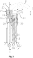
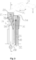
- Figures 1 , 2 and 3 depict schematically an assembly 10 for transmitting force to a gas exchange valves 12 in an internal combustion piston engine (not shown).
- Figure 2 shows a cross sectional view II-II in the figure 1 and figure 1 in turn shows cross sectional view I-I of the figure 2 .
- FIG 3 there is shown a position where the yoke is pushed down (in the direction of the figure) so as to open the gas exchange valves associated with the assembly 10.
- the assembly 10 is a valve actuation assembly for use in connection with mechanical valve train of an internal combustion engine.
- the assembly is a lash adjusting valve actuation assembly 10 which is configured to transmit force from a rocker arm 14 to an end of two valve stems 16 in an internal combustion piston engine (not shown).
- a guide pin 18 and a yoke part 20 are arranged in cooperation with each other such that the yoke part 20 is arranged movably to the guide pin 18.
- the guide pin 18 is removably attached to a cylinder head 22 of the engine.
- the particular manner of attachment may vary according to the specific application, but it may be a threaded or provided with suitable flange part, just to mention a few options.
- the guide pin comprises a guiding surface 24, which is advantageously a cylindrical guiding surface.
- the guide pin 18 is provided with a first conduit 26 for introducing lubrication oil to a contact area between the guide opening 32 and the guide pin 18.
- the contact area is arranged to be lubricated via the first conduit 26 arranged in the guide pin 18.
- the first conduit 26 is also arranged for introducing lubrication oil to the yoke part 20.
- the lubrication oil is used, in addition to lubricated the sliding surfaces, as pressurized hydraulic working medium.
- the first conduit 26 has at least one inlet at its end extending to the cylinder head and being in flow communication with a lubrication oil channel there, and at least one outlet 30 arranged open at the guiding surface 24 of the guide pin 18.
- the first conduit is in flow communication with a lubrication system of the engine when assembled for use. This makes it possible to deliver lubrication oil at elevated pressure to the valve actuation assembly according to the invention through the first conduit 26.
- the yoke part 20 is a generally of T-shaped structure. It comprises a body section 20.1 which is parallel to the guide pin 18, and two arms 20.2, 20.3 which extend sideways from the body section 20.1 of the yoke part 20. The arms are parallel with each other.
- the yoke part 20, and more particularly its body section 20.1, comprises an axially elongated guide opening 32 which has a first longitudinal axis A1.
- the guide opening 32 is axially longer than its diameter.
- the guide opening 32 is configured to receive the guide pin 18 to extend into the guide opening 32.
- the guide opening 32 is a through-hole and it comprises a guiding surface 34.
- the guiding surface is advantageously also a cylindrical guiding surface.
- the guide opening 32 extends through the yoke 20.
- the guide opening 32 is a cylindrical through hole so that guide pin 18 moves substantially freely along the guiding surface 34 without a risk of pressure formation, damping the movement of the yoke, which would be the case of a closed or blind hole.
- the guiding surface 34 of the guide opening 32 is arranged to cooperate with the guiding surface 24 of the guide pint 18 such that they together allow relative linear movement between the guide pin 18 and the yoke part 20.
- the guide pin 18 When assembled for use in a cylinder head of an engine the guide pin 18 is installed stationary to the cylinder head and the yoke part 20 is arranged to reciprocate in respect to the guide pin 18 and the cylinder head by means of the rocker arms.
- the body section 20.1 is arranged to extend radially in respect to the first longitudinal axis A1 at a side the guide opening 32 and also extend axially from an axial end of the guide opening 32.
- the part of the body section 20.1 which is arranged to extend both radially and axially in respect to the axial end of the guide opening 3 may be referred to as a yoke extension part 21.
- a yoke extension part 21 As can be seen particularly in the figures 2 and 3 , when the assembly is installed to an engine the upper end of the guide opening 32 of the yoke part 20 is lower than an upper and of the yoke part 20.
- the arms 20.2, 20.3 of the yoke part 20 are arranged to the yoke extension part 21 and the arms 20.2, 20.3 are arranged to extend to opposite directions from the yoke extension part 21 substantially perpendicularly to the first longitudinal axis A1.
- This particular structure makes it possible to provide more room for valve spring in a more confined area because the distance between the valve stems and the guide pin 18 is increased thanks to the radial extension of the body section of the yoke part 20.
- This also makes is possible to provide more space for the rocker arm, particularly because the upper end of the guide opening 32 of the yoke part 20 and also an upper end of the guide pin 18 may be at lower position than an upper and of the yoke part 20.
- the yoke part (20) is provided with a contact surface 23 configured to be in force transmission connection with the rocker arm 14, arranged in the middle between the ends of the arms 20.1,20.3.
- the contact surface is generally perpendicular to the guide opening and it surface is configured to operate as force transmission surface cooperating with the rocker arm.
- the contact surface is can alternatively be made cylindrically concave having its axis parallel with the arms 20.2, 20.3, or as spherical recess or even as flat surface and the rocker arm is provided respectively suitable means to co-operate with the contact surface, such as cylindrical or spherical surface or a roller to engage with a flat surface.
- the yoke part 20 comprises a second conduit 36 for receiving lubrication oil from the guide pin 18.
- the second conduit 36 is provided with an inlet 38 opening at the guiding surface of the elongated guide opening 32 of the yoke part 20.
- the inlet 38 has a cross sectional area greater than that of the second conduit 36.
- the cross sectional area of the inlet 38 of the second conduit 36 is also greater than the outlet 30 of the first conduit 26. This way the flow connection between the outlet 30 of the first conduit and the inlet 38 of the second conduit 36 is open even if the mutual position of the yoke part 20 and the guide pin 18 changes.
- the inlet 38 of the second conduit 36 extends, or has a length L, on the guiding surface 34 in the direction of the first longitudinal axis A1 such that the flow connection between the outlet 30 of the first conduit 26 and the second conduit 36 is ruled by mutual positions of the outlet 30 in the guiding surface 24 of the guide pin 18 and the inlet 38 of the second conduit 36 in the yoke part 20.
- the flow connection is maintained while the outlet 30 of the first conduit 26 is within the range of length L.
- the length L is at least such that the flow connection is open while the gas exchange valve is closed position.
- the length L is advantageously 10 - 50 % of the respective valve lift.
- the flow connection between the first conduit 26 and the second conduit 36 is however open at least when the gas exchange valve is closed i.e.
- the assembly 10 for transmitting force is at its resting position.
- the dimension of the inlet 38 of the second conduit in the direction of the first longitudinal axis A1 is greater than the dimension of the outlet 30 of the first conduit 26 in the direction of the first longitudinal axis A1.
- the inlet 38 may be formed as a slot into which the second conduit 36 opens.
- the engine comprises a pair of valves 12 as intake or exhaust valves which are operated simultaneously, their lifting synchronized by the yoke and thus the yoke comprises two arms, one for each valve of the valve pair.
- the arms 20.2, 20.3 comprise both a cylindrical space 40 at an end of the arms.
- the cylindrical space can be referred to simply as a cylinder.
- the end of the arm 20.3 is shown in more detailed manner in the figure 3 which is the detail A of the figure 1 .
- the lubrication oil has, when the engine is running, has substantially constant pressure and therefore the pressure obtainable into the cylindrical space is substantially the pressure of the lubrication oil of the engine.
- the first conduit 26, where the pressure of the lubrication oil is effected constantly, is in flow connection with the second conduit 36 when the relative position of the yoke part 20 in respect to the guide pin 18 is such that the outlet 30 of the first conduit 26 meets with the inlet 38.
- the second conduit has an outlet 44 opening into each one of the cylindrical spaces 40.
- the outlet 44 of the second conduit 36 opens into the cylindrical space 40 axially behind the piston member 42 so as to be capable of exert force against the piston member urging the piston member 42 to move out from the cylindrical space 40.
- the conduit 36 is provided with a plug 37 at its end.
- the second conduit 36 is provided with a one-way valve 46 in operational connection with each one of the cylindrical spaces 40.
- the cylindrical space 40 in the arm 20.2 has a second longitudinal axis A2 which is parallel to the first longitudinal axis A1. This way the movement of the piston member 42 in the cylindrical space 40 is also parallel to the movement of the yoke part 20 in respect to the guide member 18.
- the first longitudinal axis A1 is at a distance from a line connecting the second axes A2 of the cylindrical spaces at the ends of the arms 20.2, 20.3.
- the arms are of equal lengths, so the distance from the first longitudinal A1 to both of the second longitudinal axes A2 is the same.
- the piston member 42 and the cylindrical space 40 has special form by means of which the functional features thereof can be obtained.
- the cylindrical space 40 has a first axial end section 40' and a second axial end section 40".
- the piston member 42 has a first axial end section 42' and a second axial end section 42".
- the piston member 42 and the cylindrical space 40 are formed so that the first axial end section 42' of the piston member 42 is configured to fit into the first axial end section 40' of the cylindrical space 40 and the second axial end section 42" of the piston member is configured to fit into the second axial end section 40" of the cylindrical space.
- the first axial end section 40' of the cylindrical space 40 has greater diameter than the second axial end section 40" and there is a radially extending wall section 48 of the piston part 42 which is formed by transition from the first and second axial end sections of the piston member 42.
- the radially extending wall section 48 provides the surface which transmits the pressure into force urging the piston member 42 move out from the cylindrical space 40.
- the second axial end section 42" protrudes axially from the radially extending wall section 48 and is arranged to fit into the second axial end section 40" of the cylindrical space 40.
- the first axial end section 40' of the cylindrical space 40 has a first diameter D40' and the second axial end section 40" of the cylindrical space 40 has a second diameter D40".
- the first axial end section 42' of the piston member 42 has a third diameter D42' and the second axial end section 42" of the piston member 42 has a fourth diameter D42".
- the first diameter D40' is greater than the third diameter D42', such that suitable gap is provided therebetween, and the second diameter D40" is greater than the fourth diameter D42".
- the first diameter D40' is much greater than second diameter D40".
- the first diameter D40' is 2 - 5 times the second diameter D40".
- the first diameter and the second diameter are dimensioned case by case taking into account the force needed for opening the valves for example due to the valve springs.
- the cylindrical space 40 extends through the arm 20.3 of yoke part 20 and there is an annular gap 50 formed between the second axial section 42" of the piston member 42 and second axial section 40" of the cylindrical space 40 The gap is forms an air bleed conduit of the cylindrical space 40 and also a conduit for feeding lubrication oil to contact area between the piston member 42 and the end of the valve stem 16.
- the second axial section 42" of the piston member 42 and the second axial section 40" of the cylindrical space is above the first axial section 42' of the piston member and the first axial section 40' of the cylindrical space 40.
- any air present in the cylindrical space 40 or the conduits 26,36 can be removed by upwards flow through the gap 50.
- the difference between the second diameter D40" and the fourth diameter D42" is 50 - 150 ⁇ m, advantageously 0,1 mm. Even if there will be a small oil bleed off through the gap, the operation cycle is so fast in practise that the pressure drop will not affect the operation.
- the cylindrical space 40 extends through the arm 20.3 of yoke part 20 and it has an axial length L1 which naturally corresponds to the thickness of the arm at that region.
- the piston member 42 is provided with a radial extension 52 at its first axial end which has a diameter greater than the diameter of the cylindrical space. This way the radial extension is also a mechanical stopper which prevents the piston part 42 from moving farther into the cylindrical space 40.
- the piston member 42 has an axial length L2 between a base 53 of the radial extension 52 and the second axial end 54 of the piston member 42.
- the axial length L1 of the cylindrical space 40 is greater than the axial length L2 between a base 53 of the radial extension 52 and the second axial end 54 of the piston member 42 and therefore there is an oil collecting recess 56 formed in by the second axial end section 40" of the cylindrical space 40, above the second axial end section 42" of the piston member 42.
- Axial length of the oil collecting recess 56 may vary according to relative position of the piston member 42 in the cylindrical space40. Since during the operation of the engine lubrication oil is fed to the cylindrical space 40 and it may flow through the gap 50 above (or behind) the second axial section 42" of the piston member 42, into the oil collecting recess 56.
- the piston member 42 is provided with an axial through-hole 58 extending from first axial end, at the first axial end section 42' of the piston member 42 to its second axial end, at the second axial end section 42" of the piston member. This way then the engine is running an the lubrication oil flow into the cylindrical space 40, the oil flows through the annular gap 50 into the oil connecting recess 56, from which oil may be guided through the axial through-hole 58 to underside or to the first axial end of the piston member 42.
- the piston member 42 is provided at its first axial end with a circular recess 60 into which the axial through-hole 58 opens.
- the recess 60 has a plane bottom which is configured to receive the valve stem 16 when assembled for use in an internal combustion engine.
- the arrangement 10 provides lubrication oil to the contact between the valve stem 16 and the piston member 42 via the route: cylindrical space 40 - annular gap 50 - oil collecting recess 56 - through-hole 58. Lubrication of can flow out of the recess 60 via a gap between the valve stem 16 and inner cylindrical wall of the recess 60.
- the assembly operates so that during the valves 12 are closed the yoke 20 is at a position at which the flow path for the lubrication oil 26,36,44,46 is open through the first conduit 26 to the second conduit 36 and further to the cylindrical space 40 through the one-way valve 46 this causes the piston part 42 to be moved against the end of the valve stem 16 in outward direction (downward in the figures) removing any lash in the valve train.
- the valves 12 lifting commences the yoke starts to move downward in the figures, since the rocker arm 14 pushes it from opposite side to the guide pin 18.
- the lubrication oil flow path 26, 36 is closed when the inlet 38 of the second conduit 36 departs from the outlet 30 of the first conduit 26. Now the pressure prevailing in the cylindrical space 40 can be maintained for longer period of time due to the effect of the one-way valve 46. This also causes the pressure in the cylindrical space to purge via the gaps thus facilitating the lubrication of the piston member 42 and the valve stem 16.
Landscapes
- Engineering & Computer Science (AREA)
- Mechanical Engineering (AREA)
- General Engineering & Computer Science (AREA)
- Lubrication Of Internal Combustion Engines (AREA)
Abstract
Description
- The present invention relates to an assembly for transmitting force from a rocker arm to an end of two valve stems in an internal combustion piston engine according to the preamble of claim 1.
- Internal combustion engine comprises a combustion chamber in each one of it cylinders, in which gas exchange valves are used for controlling admission of the combustion air and removal of exhaust gas from the combustion chamber. It is very important that the valves are closed in tight manner and closing and opening of the valves are timed accurately to meet the demands of the combustion cycle. In mechanically actuated valves the engine is provided with a cam shaft which is rotated in synchronous action with a crank shaft of the engine at half speed to the speed of the crank shaft in a four stroke engine. The cam lobes force the valves open by pressing on the valve using an intermediate mechanism or linkage which comprises a push rod and a rocker arm, when the cam shaft is supported in the block of the engine. Such a linkage may also be referred to as a valve train.
- A rocker arm is an oscillating lever that conveys radial movement from the cam shaft lobe into linear movement at the valve to open it. One end is raised and lowered by a rotating lobe of the camshaft while the other end acts to the valve stem. When the camshaft lobe raises the first end of the arm, the second end presses down the valve stem, opening the valve. When the first end of the arm is permitted to return due to the camshafts rotation, the second end rises, allowing the valve spring to close the valve. The rocker arm comprises a first end in communication with a push rod and a second extension which is in communication with the valve. The rocker arm is supported between the extensions such that is can move, rock back and forth according to the control of the cam shaft. The rocker arm is typically lubricated by the lubrication system of the engine. The clearance of the linkage between the cam lobe and the valve must be suitable so as to enable desired accuracy of the valve timings. Such clearance may also be referred to as lash. However, there should be a mechanical clearance in the linkage in order to make sure that the valve can be closed properly and take into account thermal expansions of the parts. It is also a fact that the circumstances change during the operation and lifespan of the engine causing the change in the clearance also. The clearance is also effected by wearing of the valve sealing surface and/or a valve seat.
-
US 2019257219 A1 discloses a valve train for an internal combustion engine and an internal combustion engine comprising such a valve train with extended maintenance periods, in other words a valve train which needs a smaller amount of or no maintenance work regarding the valve lash adjustment. The document proposes to provide a rocker arm with a cavity at one end thereof and a piston arranged into the cavity such that the piston act as part of the valve actuating train. The cavity is in fluid communication with engines lubrication system via a shaft of the rocker arm such that the communication is controlled by relative position of the rocker arm to the shaft.US 2019257219 A1 discloses also an embodiment which is intended to actuate at least two valves. This arrangement comprises a bridge which for actuating at least two valves, in which a cavity at an end thereof is arranged and a piston arranged into the cavity such that the piston act as part of the valve actuating train. The cavity is closed when a rocker arm moves the valve bridge and the flow connection to the lubrication system of the engine is closed. The valve bridge is guided by a valve bridge guide which can plunge into the valve bridge depending on the actual position of the valve bridge. The valve bridge guide is used as supply-pin, supplying the cavity with the fluid depending on the relative position of the valve bridge to the valve bridge guide. - Even if the general principles of lash adjusting disclosed in
US 2019257219 A1 may be applicable as such, with regard to the two-valve actuator bridge, to proposed solution still has shortcomings to be improved. - An object of the invention is to provide an assembly for transmitting force from a rocker arm to an end of two valve stems in an internal combustion piston engine in which the performance is considerably improved compared to the prior art solutions.
- Objects of the invention can be met substantially as is disclosed in the independent claim and in the other claims describing more details of different embodiments of the invention.
- An assembly for transmitting force from a rocker arm to an end of two valve stems in an internal combustion piston engine, comprising a guide pin and a yoke part, wherein the guide pin comprising a guiding outer surface, and the yoke part comprising an axially elongated guide opening to receive the guide pin, the opening having a guiding surface arranged to cooperate with the guiding surface of the guide pin, two arms configured to transmit force from the yoke part to an end of a valve stems, and wherein the yoke part and the guide pin are arranged to cooperate with each other in linearly sliding manner such that when the guide pin is assembled for use, the yoke part is arranged movable under guidance of the guide pin in the axially elongated guide opening. Further, the axially elongated guide opening in the yoke part is a through hole and the guide pin is arranged to extend through the axially elongated guide opening and the contact area between the guide opening and the guide pin is arranged to be lubricated via a first conduit arranged in the guide pin for introducing lubrication oil to the contact area.
- By means of the assembly for transmitting force from a rocker arm to an end of two valve stems according to the invention the space available in top if a cylinder head and inside a rocker arm cover is efficiently used. Also the movement of the yoke along the guide pin is unconstrained due to the through-hole configuration. Additionally, the linear movement of the yoke part under guidance of the guide pin is effectively and reliably lubricated via the first conduit arranged in the guide pin.
- According to an embodiment of the invention the guide opening in the yoke part has a first longitudinal axis A1, and the guide opening has a first axial end and a second axial end, wherein a body section of the yoke part comprises an axial extension which extends axially further from one of the first axial end and the second axial end parallel to the first longitudinal axis A1.
- This way there is a sufficient room for a rocker arm to operate such that it reaches the yoke part over the guide pin.
- According to an embodiment of the invention the guide opening in the yoke part has a first longitudinal axis A1 and the two arms are parallel to each other and are arranged to extend to opposite directions from the axial extension of the yoke part.
- According to an embodiment of the invention a body section of the yoke part is arranged to extend radially in respect to the first longitudinal axis A1 beside the guide opening and to extend axially from an axial end of the guide opening.
- According to an embodiment of the invention the two arms each comprising a cylindrical space and a piston member arranged to each one of the cylindrical spaces at the end of the arms, configured to transmit force from the yoke part to an end a valve stem, and wherein the guide opening in the yoke part has a first longitudinal axis A1 and the cylindrical space has a second longitudinal axis A2 and the first longitudinal axis A1 is at a distance from a line connecting the second longitudinal axes A2 of the cylindrical spaces.
- Such a configuration provides required space for valve springs still minimizing the space consumption.
- According to an embodiment of the invention the yoke part comprising a second conduit for receiving lubrication oil from the guide pin having an inlet at the guiding surface of the guide opening, the first conduit in the guide pin has at least one outlet at the guiding surface of the guide pin , wherein cross sectional area of the inlet of the second conduit is greater than the outlet of the first conduit (26).
- According to an embodiment of the invention the first conduit in the guide pin has at least one outlet at the guiding surface of the guide pin, and the yoke part comprising a second conduit for receiving lubrication oil from the guide pin having an inlet at the guiding surface of the guide opening, wherein the two arms comprise a cylindrical space having a second longitudinal axis A2, at an end of the arms, wherein the first and the second longitudinal axes A1, A2 are parallel to each other, and wherein the second conduit has an outlet opening into the cylindrical space, and further a piston member arranged to each one of the cylindrical spaces in the arms, configured to transmit force from the yoke part to an end a valve stem.
- According to an embodiment of the invention the second conduit is provided with a one-way valve in operational connection with each one of the cylindrical spaces.
- This way operation of the yoke part and particularly of the piston members is precise since the one-way valve cuts the flow connection from the cylindrical spaces to the conduits feeding lubrication oil to the cylindrical space and also the flow connection between the cylindrical spaces. This in turn result in simultaneous opening of both of the valves which the valve actuation assembly is configured to open.
- According to an embodiment of the invention the piston member is provided with an axial through-hole extending from first axial end of the piston member to its second axial end.
- The exemplary embodiments of the invention presented in this patent application are not to be interpreted to pose limitations to the applicability of the appended claims. The verb "to comprise" is used in this patent application as an open limitation that does not exclude the existence of also unrecited features. The features recited in depending claims are mutually freely combinable unless otherwise explicitly stated. The novel features which are considered as characteristic of the invention are set forth in particular in the appended claims.
- In the following, the invention will be described with reference to the accompanying exemplary, schematic drawings, in which
-
Figure 1 illustrates an assembly for transmitting force to a gas exchange valves in an internal combustion piston engine according to an embodiment of the invention, -
Figure 2 illustrates a cross sectional view II-II of theFigure 1 . -
Figure 3 illustrates the cross sectional view Ii-II of theFigure 1 the assembly at a position where the valves are opened. -
Figure 4 illustrates a detail A in theFigure 1 . -
Figures 1 ,2 and3 depict schematically anassembly 10 for transmitting force to agas exchange valves 12 in an internal combustion piston engine (not shown).Figure 2 shows a cross sectional view II-II in thefigure 1 and figure 1 in turn shows cross sectional view I-I of thefigure 2 . In thefigure 3 there is shown a position where the yoke is pushed down (in the direction of the figure) so as to open the gas exchange valves associated with theassembly 10. More particularly theassembly 10 is a valve actuation assembly for use in connection with mechanical valve train of an internal combustion engine. According to an embodiment of the invention the assembly is a lash adjustingvalve actuation assembly 10 which is configured to transmit force from arocker arm 14 to an end of twovalve stems 16 in an internal combustion piston engine (not shown). In the valve actuation assembly 10 aguide pin 18 and ayoke part 20 are arranged in cooperation with each other such that theyoke part 20 is arranged movably to theguide pin 18. In the embodiment shown in the figures, theguide pin 18 is removably attached to acylinder head 22 of the engine. The particular manner of attachment may vary according to the specific application, but it may be a threaded or provided with suitable flange part, just to mention a few options. The guide pin comprises a guidingsurface 24, which is advantageously a cylindrical guiding surface. Theguide pin 18 is provided with afirst conduit 26 for introducing lubrication oil to a contact area between theguide opening 32 and theguide pin 18. The contact area is arranged to be lubricated via thefirst conduit 26 arranged in theguide pin 18. Thefirst conduit 26 is also arranged for introducing lubrication oil to theyoke part 20. In the present invention the lubrication oil is used, in addition to lubricated the sliding surfaces, as pressurized hydraulic working medium. Thefirst conduit 26 has at least one inlet at its end extending to the cylinder head and being in flow communication with a lubrication oil channel there, and at least oneoutlet 30 arranged open at the guidingsurface 24 of theguide pin 18. The first conduit is in flow communication with a lubrication system of the engine when assembled for use. This makes it possible to deliver lubrication oil at elevated pressure to the valve actuation assembly according to the invention through thefirst conduit 26. - The
yoke part 20 is a generally of T-shaped structure. It comprises a body section 20.1 which is parallel to theguide pin 18, and two arms 20.2, 20.3 which extend sideways from the body section 20.1 of theyoke part 20. The arms are parallel with each other. Theyoke part 20, and more particularly its body section 20.1, comprises an axiallyelongated guide opening 32 which has a first longitudinal axis A1. Theguide opening 32 is axially longer than its diameter. Theguide opening 32 is configured to receive theguide pin 18 to extend into theguide opening 32. Theguide opening 32 is a through-hole and it comprises a guidingsurface 34. The guiding surface is advantageously also a cylindrical guiding surface. Theguide opening 32 extends through theyoke 20. Theguide opening 32 is a cylindrical through hole so thatguide pin 18 moves substantially freely along the guidingsurface 34 without a risk of pressure formation, damping the movement of the yoke, which would be the case of a closed or blind hole. The guidingsurface 34 of theguide opening 32 is arranged to cooperate with the guidingsurface 24 of theguide pint 18 such that they together allow relative linear movement between theguide pin 18 and theyoke part 20. When assembled for use in a cylinder head of an engine theguide pin 18 is installed stationary to the cylinder head and theyoke part 20 is arranged to reciprocate in respect to theguide pin 18 and the cylinder head by means of the rocker arms. - The body section 20.1 is arranged to extend radially in respect to the first longitudinal axis A1 at a side the
guide opening 32 and also extend axially from an axial end of theguide opening 32. The part of the body section 20.1 which is arranged to extend both radially and axially in respect to the axial end of the guide opening 3 may be referred to as ayoke extension part 21. As can be seen particularly in thefigures 2 and3 , when the assembly is installed to an engine the upper end of the guide opening 32 of theyoke part 20 is lower than an upper and of theyoke part 20. Also, the arms 20.2, 20.3 of theyoke part 20 are arranged to theyoke extension part 21 and the arms 20.2, 20.3 are arranged to extend to opposite directions from theyoke extension part 21 substantially perpendicularly to the first longitudinal axis A1. This particular structure makes it possible to provide more room for valve spring in a more confined area because the distance between the valve stems and theguide pin 18 is increased thanks to the radial extension of the body section of theyoke part 20. This also makes is possible to provide more space for the rocker arm, particularly because the upper end of the guide opening 32 of theyoke part 20 and also an upper end of theguide pin 18 may be at lower position than an upper and of theyoke part 20. - The yoke part (20) is provided with a
contact surface 23 configured to be in force transmission connection with therocker arm 14, arranged in the middle between the ends of the arms 20.1,20.3. The contact surface is generally perpendicular to the guide opening and it surface is configured to operate as force transmission surface cooperating with the rocker arm. The contact surface is can alternatively be made cylindrically concave having its axis parallel with the arms 20.2, 20.3, or as spherical recess or even as flat surface and the rocker arm is provided respectively suitable means to co-operate with the contact surface, such as cylindrical or spherical surface or a roller to engage with a flat surface. - The
yoke part 20 comprises asecond conduit 36 for receiving lubrication oil from theguide pin 18. Thesecond conduit 36 is provided with aninlet 38 opening at the guiding surface of the elongated guide opening 32 of theyoke part 20. Theinlet 38 has a cross sectional area greater than that of thesecond conduit 36. And what is more important for the function of the assembly, the cross sectional area of theinlet 38 of thesecond conduit 36 is also greater than theoutlet 30 of thefirst conduit 26. This way the flow connection between theoutlet 30 of the first conduit and theinlet 38 of thesecond conduit 36 is open even if the mutual position of theyoke part 20 and theguide pin 18 changes. Theinlet 38 of thesecond conduit 36 extends, or has a length L, on the guidingsurface 34 in the direction of the first longitudinal axis A1 such that the flow connection between theoutlet 30 of thefirst conduit 26 and thesecond conduit 36 is ruled by mutual positions of theoutlet 30 in the guidingsurface 24 of theguide pin 18 and theinlet 38 of thesecond conduit 36 in theyoke part 20. The flow connection is maintained while theoutlet 30 of thefirst conduit 26 is within the range of length L. The length L is at least such that the flow connection is open while the gas exchange valve is closed position. The length L is advantageously 10 - 50 % of the respective valve lift. The flow connection between thefirst conduit 26 and thesecond conduit 36 is however open at least when the gas exchange valve is closed i.e. theassembly 10 for transmitting force is at its resting position. In other words, the dimension of theinlet 38 of the second conduit in the direction of the first longitudinal axis A1 is greater than the dimension of theoutlet 30 of thefirst conduit 26 in the direction of the first longitudinal axis A1. Theinlet 38 may be formed as a slot into which thesecond conduit 36 opens. - In the embodiment shown in the figures the engine comprises a pair of
valves 12 as intake or exhaust valves which are operated simultaneously, their lifting synchronized by the yoke and thus the yoke comprises two arms, one for each valve of the valve pair. The arms 20.2, 20.3 comprise both acylindrical space 40 at an end of the arms. The cylindrical space can be referred to simply as a cylinder. The end of the arm 20.3 is shown in more detailed manner in thefigure 3 which is the detail A of thefigure 1 . There is apiston member 42 arranged to each one of thecylindrical spaces 40 in the arms 20.2, 20.3, configured to transmit force from the yoke part to an end of the avalve stem 16. The lubrication oil has, when the engine is running, has substantially constant pressure and therefore the pressure obtainable into the cylindrical space is substantially the pressure of the lubrication oil of the engine. Thefirst conduit 26, where the pressure of the lubrication oil is effected constantly, is in flow connection with thesecond conduit 36 when the relative position of theyoke part 20 in respect to theguide pin 18 is such that theoutlet 30 of thefirst conduit 26 meets with theinlet 38. - As can be seen in the
figure 1 andfigure 4 the second conduit has anoutlet 44 opening into each one of thecylindrical spaces 40. Theoutlet 44 of thesecond conduit 36 opens into thecylindrical space 40 axially behind thepiston member 42 so as to be capable of exert force against the piston member urging thepiston member 42 to move out from thecylindrical space 40. Theconduit 36 is provided with aplug 37 at its end. - The
second conduit 36 is provided with a one-way valve 46 in operational connection with each one of thecylindrical spaces 40. In practise this means that the one-way valve 46 dedicated to onecylindrical space 40 effects only to operation of onecylindrical space 40 such that the lubrication oil fed through thesecond conduit 36 is prevented from flowing back to the conduit. This way the sustainment of lubrication oil pressure in thecylindrical space 40 is not effected by tightness of theinlet 38 of thesecond conduit 36 against the guidingsurface 24 of theguide pin 18. - The
cylindrical space 40 in the arm 20.2 has a second longitudinal axis A2 which is parallel to the first longitudinal axis A1. This way the movement of thepiston member 42 in thecylindrical space 40 is also parallel to the movement of theyoke part 20 in respect to theguide member 18. The first longitudinal axis A1 is at a distance from a line connecting the second axes A2 of the cylindrical spaces at the ends of the arms 20.2, 20.3. The arms are of equal lengths, so the distance from the first longitudinal A1 to both of the second longitudinal axes A2 is the same. - The
piston member 42 and thecylindrical space 40 has special form by means of which the functional features thereof can be obtained. Thecylindrical space 40 has a first axial end section 40' and a secondaxial end section 40". Likewise thepiston member 42 has a first axial end section 42' and a secondaxial end section 42". Thepiston member 42 and thecylindrical space 40 are formed so that the first axial end section 42' of thepiston member 42 is configured to fit into the first axial end section 40' of thecylindrical space 40 and the secondaxial end section 42" of the piston member is configured to fit into the secondaxial end section 40" of the cylindrical space. More particularly, the first axial end section 40' of thecylindrical space 40 has greater diameter than the secondaxial end section 40" and there is a radially extendingwall section 48 of thepiston part 42 which is formed by transition from the first and second axial end sections of thepiston member 42. The radially extendingwall section 48 provides the surface which transmits the pressure into force urging thepiston member 42 move out from thecylindrical space 40. The secondaxial end section 42" protrudes axially from the radially extendingwall section 48 and is arranged to fit into the secondaxial end section 40" of thecylindrical space 40. - The first axial end section 40' of the
cylindrical space 40 has a first diameter D40' and the secondaxial end section 40" of thecylindrical space 40 has a second diameter D40". Respectively, the first axial end section 42' of thepiston member 42 has a third diameter D42' and the secondaxial end section 42" of thepiston member 42 has a fourth diameter D42". In order to have thepiston member 42 according to the invention be assemblable into thecylindrical space 40 the first diameter D40' is greater than the third diameter D42', such that suitable gap is provided therebetween, and the second diameter D40" is greater than the fourth diameter D42". Also, the first diameter D40' is much greater than second diameter D40". Advantageously the first diameter D40' is 2 - 5 times the second diameter D40". The first diameter and the second diameter are dimensioned case by case taking into account the force needed for opening the valves for example due to the valve springs. Thecylindrical space 40 extends through the arm 20.3 ofyoke part 20 and there is anannular gap 50 formed between the secondaxial section 42" of thepiston member 42 and secondaxial section 40" of thecylindrical space 40 The gap is forms an air bleed conduit of thecylindrical space 40 and also a conduit for feeding lubrication oil to contact area between thepiston member 42 and the end of thevalve stem 16. When installed for use theassembly 10 is in the position shown in the figures an therefore the secondaxial section 42" of thepiston member 42 and the secondaxial section 40" of the cylindrical space is above the first axial section 42' of the piston member and the first axial section 40' of thecylindrical space 40. Thus any air present in thecylindrical space 40 or theconduits gap 50. Advantageously the difference between the second diameter D40" and the fourth diameter D42" is 50 - 150 µm, advantageously 0,1 mm. Even if there will be a small oil bleed off through the gap, the operation cycle is so fast in practise that the pressure drop will not affect the operation. - The
cylindrical space 40 extends through the arm 20.3 ofyoke part 20 and it has an axial length L1 which naturally corresponds to the thickness of the arm at that region. Thepiston member 42 is provided with aradial extension 52 at its first axial end which has a diameter greater than the diameter of the cylindrical space. This way the radial extension is also a mechanical stopper which prevents thepiston part 42 from moving farther into thecylindrical space 40. Thepiston member 42 has an axial length L2 between a base 53 of theradial extension 52 and the secondaxial end 54 of thepiston member 42. The axial length L1 of thecylindrical space 40 is greater than the axial length L2 between a base 53 of theradial extension 52 and the secondaxial end 54 of thepiston member 42 and therefore there is anoil collecting recess 56 formed in by the secondaxial end section 40" of thecylindrical space 40, above the secondaxial end section 42" of thepiston member 42. Axial length of theoil collecting recess 56 may vary according to relative position of thepiston member 42 in the cylindrical space40. Since during the operation of the engine lubrication oil is fed to thecylindrical space 40 and it may flow through thegap 50 above (or behind) the secondaxial section 42" of thepiston member 42, into theoil collecting recess 56. Thepiston member 42 is provided with an axial through-hole 58 extending from first axial end, at the first axial end section 42' of thepiston member 42 to its second axial end, at the secondaxial end section 42" of the piston member. This way then the engine is running an the lubrication oil flow into thecylindrical space 40, the oil flows through theannular gap 50 into theoil connecting recess 56, from which oil may be guided through the axial through-hole 58 to underside or to the first axial end of thepiston member 42. Thepiston member 42 is provided at its first axial end with acircular recess 60 into which the axial through-hole 58 opens. Therecess 60 has a plane bottom which is configured to receive thevalve stem 16 when assembled for use in an internal combustion engine. This way thearrangement 10 provides lubrication oil to the contact between thevalve stem 16 and thepiston member 42 via the route: cylindrical space 40 - annular gap 50 - oil collecting recess 56 - through-hole 58. Lubrication of can flow out of therecess 60 via a gap between thevalve stem 16 and inner cylindrical wall of therecess 60. - The assembly operates so that during the
valves 12 are closed theyoke 20 is at a position at which the flow path for thelubrication oil first conduit 26 to thesecond conduit 36 and further to thecylindrical space 40 through the one-way valve 46 this causes thepiston part 42 to be moved against the end of thevalve stem 16 in outward direction (downward in the figures) removing any lash in the valve train. When thevalves 12 lifting commences the yoke starts to move downward in the figures, since therocker arm 14 pushes it from opposite side to theguide pin 18. The lubricationoil flow path inlet 38 of thesecond conduit 36 departs from theoutlet 30 of thefirst conduit 26. Now the pressure prevailing in thecylindrical space 40 can be maintained for longer period of time due to the effect of the one-way valve 46. This also causes the pressure in the cylindrical space to purge via the gaps thus facilitating the lubrication of thepiston member 42 and thevalve stem 16. - While the invention has been described herein by way of examples in connection with what are, at present, considered to be the most preferred embodiments, it is to be understood that the invention is not limited to the disclosed embodiments, but is intended to cover various combinations or modifications of its features, and several other applications included within the scope of the invention, as defined in the appended claims. The details mentioned in connection with any embodiment above may be used in connection with another embodiment when such combination is technically feasible.
Claims (9)
- An assembly (10) for transmitting force from a rocker arm (14) to an end of two valve stems (16) in an internal combustion piston engine, comprising a guide pin (18) and a yoke part (20), wherein
the guide pin (18) comprisinga guiding outer surface (24), and
the yoke part (20) comprisingan axially elongated guide opening (32) to receive the guide pin (18), the opening having a guiding surface (34) arranged to cooperate with the guiding surface (24) of the guide pin (18),two arms (20.2, 20.3) configured to transmit force from the yoke part (20) to an end of a valve stems (16), and wherein
the yoke part (20) and the guide pin (18) are arranged to cooperate with each other in linearly sliding manner such that when the guide pin (18) is assembled for use, the yoke part (20) is arranged movable under guidance of the guide pin (18) in the axially elongated guide opening (32), characterized in that axially elongated guide opening (32) in the yoke part (18) is a through hole and that the guide pin (18) is arranged to extend through the axially elongated guide opening (32) wherein contact area between the guide opening (32) and the guide pin (18) is arranged to be lubricated via a first conduit (26) arranged in the guide pin (18) for introducing lubrication oil to the contact area. - An assembly (10) according to claim 1, characterized in that the guide opening in the yoke part (20) has a first longitudinal axis (A1), and the guide opening (32) has a first axial end and a second axial end, wherein a body section (20.1) of the yoke part (20) comprises an axial extension which extends axially further from one of the first axial end and the second axial end parallel to the first longitudinal axis (A1).
- An assembly (10) according to claim 1 or 2, characterized in that the guide opening in the yoke part (20) has a first longitudinal axis (A1) and the two arms are parallel to each other and are arranged to extend to opposite directions from the axial extension of the yoke part.
- An assembly (10) according to claim 1 2 or 3, characterized in that a body section (20.1) of the yoke part (20) is arranged to extend radially in respect to the first longitudinal axis (A1) beside the guide opening (32) and to extend axially from an axial end of the guide opening (32).
- An assembly (10) according to anyone of the preceding claims, characterized in that the two arms each comprising a cylindrical space (40) and a piston member (42) arranged to each one of the cylindrical spaces (40) at the end of the arms (20.2, 20.3), configured to transmit force from the yoke part (20) to an end a valve stem (16), and wherein the guide opening in the yoke part (20) has a first longitudinal axis (A1) and the cylindrical space has a second longitudinal axis (A2) and the first longitudinal axis (A1) is at a distance from a line connecting the second longitudinal axes (A2) of the cylindrical spaces (4).
- An assembly (10) according to claim 1, characterized in that the yoke part (20) comprising a second conduit (36) for receiving lubrication oil from the guide pin (18) having an inlet (38) at the guiding surface (34) of the guide opening (32), the first conduit (26) in the guide pin (18) has at least one outlet (30) at the guiding surface (24) of the guide pin (18), wherein cross sectional area of the inlet (38) of the second conduit (36) is greater than the outlet (30) of the first conduit (26).
- An assembly (10) according to claim 1, characterized in that the first conduit (26) in the guide pin (18) has at least one outlet (30) at the guiding surface (24) of the guide pin (18), and the yoke part (20) comprising a second conduit (36) for receiving lubrication oil from the guide pin (18) having an inlet (38) at the guiding surface (34) of the guide opening (32), wherein the two arms (20.2, 20.3) comprise a cylindrical space (40) having a second longitudinal axis (A2), at an end of the arms (20.2, 20.3), wherein the first and the second longitudinal axes (A1, A2) are parallel to each other, and wherein the second conduit (36) has an outlet (44) opening into the cylindrical space (40), and further a piston member (42) arranged to each one of the cylindrical spaces (40) in the arms (20.2, 20.3), configured to transmit force from the yoke part (20) to an end a valve stem (16).
- An assembly (10) according to claim 6, characterized in that the second conduit (36) is provided with a one-way valve (46) in operational connection with each one of the cylindrical spaces (40).
- An assembly (10) according to anyone of the claims 6 or 7, characterized in that the piston member (42) is provided with an axial through-hole (58) extending from first axial end of the piston member (42) to its second axial end.
Priority Applications (1)
| Application Number | Priority Date | Filing Date | Title |
|---|---|---|---|
| EP19213405.4A EP3832076B1 (en) | 2019-12-04 | 2019-12-04 | An assembly for transmitting force from a rocker arm to ends of two valve stems in an internal combustion piston engine |
Applications Claiming Priority (1)
| Application Number | Priority Date | Filing Date | Title |
|---|---|---|---|
| EP19213405.4A EP3832076B1 (en) | 2019-12-04 | 2019-12-04 | An assembly for transmitting force from a rocker arm to ends of two valve stems in an internal combustion piston engine |
Publications (2)
| Publication Number | Publication Date |
|---|---|
| EP3832076A1 true EP3832076A1 (en) | 2021-06-09 |
| EP3832076B1 EP3832076B1 (en) | 2022-08-10 |
Family
ID=68771415
Family Applications (1)
| Application Number | Title | Priority Date | Filing Date |
|---|---|---|---|
| EP19213405.4A Active EP3832076B1 (en) | 2019-12-04 | 2019-12-04 | An assembly for transmitting force from a rocker arm to ends of two valve stems in an internal combustion piston engine |
Country Status (1)
| Country | Link |
|---|---|
| EP (1) | EP3832076B1 (en) |
Cited By (2)
| Publication number | Priority date | Publication date | Assignee | Title |
|---|---|---|---|---|
| CN117581006A (en) * | 2021-07-12 | 2024-02-20 | 雅各布斯车辆系统公司 | Valve bridge restraints and guides and related methods |
| CN118900949A (en) * | 2022-03-15 | 2024-11-05 | 伊顿智能动力有限公司 | Valve bridge stabilizer for engine braking |
Citations (5)
| Publication number | Priority date | Publication date | Assignee | Title |
|---|---|---|---|---|
| JPH07247812A (en) * | 1994-03-07 | 1995-09-26 | Komatsu Ltd | Engine valve gear |
| JPH09112233A (en) * | 1995-10-20 | 1997-04-28 | Hino Motors Ltd | Engine valve mechanism |
| WO2009048410A1 (en) * | 2007-10-12 | 2009-04-16 | Scania Cv Ab (Publ) | Valve bridge in a combustion engine |
| DE202019102290U1 (en) * | 2019-04-24 | 2019-04-30 | Schaeffler Technologies AG & Co. KG | Bar-like solid bridge for a valve train of a heavy-duty internal combustion engine |
| US20190257219A1 (en) | 2017-12-14 | 2019-08-22 | Innio Jenbacher Gmbh & Co Og | Valve train for an internal combustion engine |
-
2019
- 2019-12-04 EP EP19213405.4A patent/EP3832076B1/en active Active
Patent Citations (5)
| Publication number | Priority date | Publication date | Assignee | Title |
|---|---|---|---|---|
| JPH07247812A (en) * | 1994-03-07 | 1995-09-26 | Komatsu Ltd | Engine valve gear |
| JPH09112233A (en) * | 1995-10-20 | 1997-04-28 | Hino Motors Ltd | Engine valve mechanism |
| WO2009048410A1 (en) * | 2007-10-12 | 2009-04-16 | Scania Cv Ab (Publ) | Valve bridge in a combustion engine |
| US20190257219A1 (en) | 2017-12-14 | 2019-08-22 | Innio Jenbacher Gmbh & Co Og | Valve train for an internal combustion engine |
| DE202019102290U1 (en) * | 2019-04-24 | 2019-04-30 | Schaeffler Technologies AG & Co. KG | Bar-like solid bridge for a valve train of a heavy-duty internal combustion engine |
Cited By (3)
| Publication number | Priority date | Publication date | Assignee | Title |
|---|---|---|---|---|
| CN117581006A (en) * | 2021-07-12 | 2024-02-20 | 雅各布斯车辆系统公司 | Valve bridge restraints and guides and related methods |
| EP4370785A4 (en) * | 2021-07-12 | 2025-05-21 | Jacobs Vehicle Systems, Inc. | Valve bridge constraints and guides and related methods |
| CN118900949A (en) * | 2022-03-15 | 2024-11-05 | 伊顿智能动力有限公司 | Valve bridge stabilizer for engine braking |
Also Published As
| Publication number | Publication date |
|---|---|
| EP3832076B1 (en) | 2022-08-10 |
Similar Documents
| Publication | Publication Date | Title |
|---|---|---|
| US7921818B2 (en) | Valve control for reciprocating piston internal combustion engine | |
| EP2094949B1 (en) | Dual lift rocker arm latch mechanism andactuation arrangement therefor | |
| JPH048604B2 (en) | ||
| US7464678B2 (en) | Hydraulic lash adjuster | |
| EP2711512A1 (en) | Reset type rocker braking method and device | |
| EP2538043B1 (en) | Hydraulic lash adjuster including band of radial recirculation openings | |
| EP3832076B1 (en) | An assembly for transmitting force from a rocker arm to ends of two valve stems in an internal combustion piston engine | |
| KR100299302B1 (en) | Valve control means | |
| CN110159383B (en) | Switchable rocker arm with clearance adjustment | |
| US7617807B2 (en) | Engine and valvetrain with dual pushrod lifters and independent lash adjustment | |
| US7458350B2 (en) | Engine/valvetrain with shaft-mounted cam followers having dual independent lash adjusters | |
| CN205477798U (en) | A round pin and valve actuating system for having valve actuating system of rocking arm | |
| CN108397252B (en) | Hydraulic lash adjuster | |
| JP4639130B2 (en) | INTERNAL COMBUSTION ENGINE HAVING HYDRAULIC OPERATING UNIT FOR CONTROLLING VALVE BY ROCKING OPERATION | |
| US6782855B1 (en) | Valve train and method for reducing oil flow to deactivated engine valves | |
| US20190257219A1 (en) | Valve train for an internal combustion engine | |
| CN205370669U (en) | Valve body, valve module and xarm subassembly | |
| WO2021110250A1 (en) | An assembly for transmitting force from a rocker arm to an end of two valve stems in an internal combustion piston engine | |
| US6880507B2 (en) | Internal combustion engine with switchable cam follower | |
| EP4090838B1 (en) | Latch assembly and compact rocker arm assembly | |
| WO2013112316A1 (en) | Deactivating hydraulic valve lash adjuster/compensator with temporary lash compensation deactivation | |
| EP3596317B1 (en) | A control arrangement for a gas exchange valve in an internal combustion piston engine and method of operating a control arrangement for a gas exchange valve in an internal combustion engine | |
| EP0857857B1 (en) | Rocker arm assembly | |
| JPS63117109A (en) | Valve system for internal combustion engine | |
| US8869760B2 (en) | Hydraulic valve actuator system and engine incorporating same |
Legal Events
| Date | Code | Title | Description |
|---|---|---|---|
| PUAI | Public reference made under article 153(3) epc to a published international application that has entered the european phase |
Free format text: ORIGINAL CODE: 0009012 |
|
| STAA | Information on the status of an ep patent application or granted ep patent |
Free format text: STATUS: THE APPLICATION HAS BEEN PUBLISHED |
|
| AK | Designated contracting states |
Kind code of ref document: A1 Designated state(s): AL AT BE BG CH CY CZ DE DK EE ES FI FR GB GR HR HU IE IS IT LI LT LU LV MC MK MT NL NO PL PT RO RS SE SI SK SM TR |
|
| STAA | Information on the status of an ep patent application or granted ep patent |
Free format text: STATUS: REQUEST FOR EXAMINATION WAS MADE |
|
| 17P | Request for examination filed |
Effective date: 20211008 |
|
| RBV | Designated contracting states (corrected) |
Designated state(s): AL AT BE BG CH CY CZ DE DK EE ES FI FR GB GR HR HU IE IS IT LI LT LU LV MC MK MT NL NO PL PT RO RS SE SI SK SM TR |
|
| GRAP | Despatch of communication of intention to grant a patent |
Free format text: ORIGINAL CODE: EPIDOSNIGR1 |
|
| STAA | Information on the status of an ep patent application or granted ep patent |
Free format text: STATUS: GRANT OF PATENT IS INTENDED |
|
| INTG | Intention to grant announced |
Effective date: 20220325 |
|
| GRAS | Grant fee paid |
Free format text: ORIGINAL CODE: EPIDOSNIGR3 |
|
| GRAA | (expected) grant |
Free format text: ORIGINAL CODE: 0009210 |
|
| STAA | Information on the status of an ep patent application or granted ep patent |
Free format text: STATUS: THE PATENT HAS BEEN GRANTED |
|
| AK | Designated contracting states |
Kind code of ref document: B1 Designated state(s): AL AT BE BG CH CY CZ DE DK EE ES FI FR GB GR HR HU IE IS IT LI LT LU LV MC MK MT NL NO PL PT RO RS SE SI SK SM TR |
|
| REG | Reference to a national code |
Ref country code: AT Ref legal event code: REF Ref document number: 1510699 Country of ref document: AT Kind code of ref document: T Effective date: 20220815 Ref country code: CH Ref legal event code: EP |
|
| REG | Reference to a national code |
Ref country code: IE Ref legal event code: FG4D |
|
| REG | Reference to a national code |
Ref country code: DE Ref legal event code: R096 Ref document number: 602019018058 Country of ref document: DE |
|
| REG | Reference to a national code |
Ref country code: NL Ref legal event code: MP Effective date: 20220810 |
|
| REG | Reference to a national code |
Ref country code: LT Ref legal event code: MG9D |
|
| PG25 | Lapsed in a contracting state [announced via postgrant information from national office to epo] |
Ref country code: SE Free format text: LAPSE BECAUSE OF FAILURE TO SUBMIT A TRANSLATION OF THE DESCRIPTION OR TO PAY THE FEE WITHIN THE PRESCRIBED TIME-LIMIT Effective date: 20220810 Ref country code: RS Free format text: LAPSE BECAUSE OF FAILURE TO SUBMIT A TRANSLATION OF THE DESCRIPTION OR TO PAY THE FEE WITHIN THE PRESCRIBED TIME-LIMIT Effective date: 20220810 Ref country code: PT Free format text: LAPSE BECAUSE OF FAILURE TO SUBMIT A TRANSLATION OF THE DESCRIPTION OR TO PAY THE FEE WITHIN THE PRESCRIBED TIME-LIMIT Effective date: 20221212 Ref country code: NO Free format text: LAPSE BECAUSE OF FAILURE TO SUBMIT A TRANSLATION OF THE DESCRIPTION OR TO PAY THE FEE WITHIN THE PRESCRIBED TIME-LIMIT Effective date: 20221110 Ref country code: NL Free format text: LAPSE BECAUSE OF FAILURE TO SUBMIT A TRANSLATION OF THE DESCRIPTION OR TO PAY THE FEE WITHIN THE PRESCRIBED TIME-LIMIT Effective date: 20220810 Ref country code: LV Free format text: LAPSE BECAUSE OF FAILURE TO SUBMIT A TRANSLATION OF THE DESCRIPTION OR TO PAY THE FEE WITHIN THE PRESCRIBED TIME-LIMIT Effective date: 20220810 Ref country code: LT Free format text: LAPSE BECAUSE OF FAILURE TO SUBMIT A TRANSLATION OF THE DESCRIPTION OR TO PAY THE FEE WITHIN THE PRESCRIBED TIME-LIMIT Effective date: 20220810 Ref country code: FI Free format text: LAPSE BECAUSE OF FAILURE TO SUBMIT A TRANSLATION OF THE DESCRIPTION OR TO PAY THE FEE WITHIN THE PRESCRIBED TIME-LIMIT Effective date: 20220810 |
|
| REG | Reference to a national code |
Ref country code: AT Ref legal event code: MK05 Ref document number: 1510699 Country of ref document: AT Kind code of ref document: T Effective date: 20220810 |
|
| PG25 | Lapsed in a contracting state [announced via postgrant information from national office to epo] |
Ref country code: PL Free format text: LAPSE BECAUSE OF FAILURE TO SUBMIT A TRANSLATION OF THE DESCRIPTION OR TO PAY THE FEE WITHIN THE PRESCRIBED TIME-LIMIT Effective date: 20220810 Ref country code: IS Free format text: LAPSE BECAUSE OF FAILURE TO SUBMIT A TRANSLATION OF THE DESCRIPTION OR TO PAY THE FEE WITHIN THE PRESCRIBED TIME-LIMIT Effective date: 20221210 Ref country code: HR Free format text: LAPSE BECAUSE OF FAILURE TO SUBMIT A TRANSLATION OF THE DESCRIPTION OR TO PAY THE FEE WITHIN THE PRESCRIBED TIME-LIMIT Effective date: 20220810 Ref country code: GR Free format text: LAPSE BECAUSE OF FAILURE TO SUBMIT A TRANSLATION OF THE DESCRIPTION OR TO PAY THE FEE WITHIN THE PRESCRIBED TIME-LIMIT Effective date: 20221111 |
|
| PG25 | Lapsed in a contracting state [announced via postgrant information from national office to epo] |
Ref country code: SM Free format text: LAPSE BECAUSE OF FAILURE TO SUBMIT A TRANSLATION OF THE DESCRIPTION OR TO PAY THE FEE WITHIN THE PRESCRIBED TIME-LIMIT Effective date: 20220810 Ref country code: RO Free format text: LAPSE BECAUSE OF FAILURE TO SUBMIT A TRANSLATION OF THE DESCRIPTION OR TO PAY THE FEE WITHIN THE PRESCRIBED TIME-LIMIT Effective date: 20220810 Ref country code: ES Free format text: LAPSE BECAUSE OF FAILURE TO SUBMIT A TRANSLATION OF THE DESCRIPTION OR TO PAY THE FEE WITHIN THE PRESCRIBED TIME-LIMIT Effective date: 20220810 Ref country code: DK Free format text: LAPSE BECAUSE OF FAILURE TO SUBMIT A TRANSLATION OF THE DESCRIPTION OR TO PAY THE FEE WITHIN THE PRESCRIBED TIME-LIMIT Effective date: 20220810 Ref country code: CZ Free format text: LAPSE BECAUSE OF FAILURE TO SUBMIT A TRANSLATION OF THE DESCRIPTION OR TO PAY THE FEE WITHIN THE PRESCRIBED TIME-LIMIT Effective date: 20220810 Ref country code: AT Free format text: LAPSE BECAUSE OF FAILURE TO SUBMIT A TRANSLATION OF THE DESCRIPTION OR TO PAY THE FEE WITHIN THE PRESCRIBED TIME-LIMIT Effective date: 20220810 |
|
| REG | Reference to a national code |
Ref country code: DE Ref legal event code: R097 Ref document number: 602019018058 Country of ref document: DE |
|
| PG25 | Lapsed in a contracting state [announced via postgrant information from national office to epo] |
Ref country code: SK Free format text: LAPSE BECAUSE OF FAILURE TO SUBMIT A TRANSLATION OF THE DESCRIPTION OR TO PAY THE FEE WITHIN THE PRESCRIBED TIME-LIMIT Effective date: 20220810 Ref country code: EE Free format text: LAPSE BECAUSE OF FAILURE TO SUBMIT A TRANSLATION OF THE DESCRIPTION OR TO PAY THE FEE WITHIN THE PRESCRIBED TIME-LIMIT Effective date: 20220810 |
|
| PLBE | No opposition filed within time limit |
Free format text: ORIGINAL CODE: 0009261 |
|
| STAA | Information on the status of an ep patent application or granted ep patent |
Free format text: STATUS: NO OPPOSITION FILED WITHIN TIME LIMIT |
|
| PG25 | Lapsed in a contracting state [announced via postgrant information from national office to epo] |
Ref country code: AL Free format text: LAPSE BECAUSE OF FAILURE TO SUBMIT A TRANSLATION OF THE DESCRIPTION OR TO PAY THE FEE WITHIN THE PRESCRIBED TIME-LIMIT Effective date: 20220810 |
|
| 26N | No opposition filed |
Effective date: 20230511 |
|
| REG | Reference to a national code |
Ref country code: CH Ref legal event code: PL |
|
| REG | Reference to a national code |
Ref country code: BE Ref legal event code: MM Effective date: 20221231 |
|
| PG25 | Lapsed in a contracting state [announced via postgrant information from national office to epo] |
Ref country code: SI Free format text: LAPSE BECAUSE OF FAILURE TO SUBMIT A TRANSLATION OF THE DESCRIPTION OR TO PAY THE FEE WITHIN THE PRESCRIBED TIME-LIMIT Effective date: 20220810 Ref country code: LU Free format text: LAPSE BECAUSE OF NON-PAYMENT OF DUE FEES Effective date: 20221204 |
|
| PG25 | Lapsed in a contracting state [announced via postgrant information from national office to epo] |
Ref country code: LI Free format text: LAPSE BECAUSE OF NON-PAYMENT OF DUE FEES Effective date: 20221231 Ref country code: IE Free format text: LAPSE BECAUSE OF NON-PAYMENT OF DUE FEES Effective date: 20221204 Ref country code: CH Free format text: LAPSE BECAUSE OF NON-PAYMENT OF DUE FEES Effective date: 20221231 |
|
| PG25 | Lapsed in a contracting state [announced via postgrant information from national office to epo] |
Ref country code: FR Free format text: LAPSE BECAUSE OF NON-PAYMENT OF DUE FEES Effective date: 20221231 Ref country code: BE Free format text: LAPSE BECAUSE OF NON-PAYMENT OF DUE FEES Effective date: 20221231 |
|
| PG25 | Lapsed in a contracting state [announced via postgrant information from national office to epo] |
Ref country code: CY Free format text: LAPSE BECAUSE OF FAILURE TO SUBMIT A TRANSLATION OF THE DESCRIPTION OR TO PAY THE FEE WITHIN THE PRESCRIBED TIME-LIMIT Effective date: 20220810 |
|
| PG25 | Lapsed in a contracting state [announced via postgrant information from national office to epo] |
Ref country code: MK Free format text: LAPSE BECAUSE OF FAILURE TO SUBMIT A TRANSLATION OF THE DESCRIPTION OR TO PAY THE FEE WITHIN THE PRESCRIBED TIME-LIMIT Effective date: 20220810 Ref country code: IT Free format text: LAPSE BECAUSE OF FAILURE TO SUBMIT A TRANSLATION OF THE DESCRIPTION OR TO PAY THE FEE WITHIN THE PRESCRIBED TIME-LIMIT Effective date: 20220810 Ref country code: HU Free format text: LAPSE BECAUSE OF FAILURE TO SUBMIT A TRANSLATION OF THE DESCRIPTION OR TO PAY THE FEE WITHIN THE PRESCRIBED TIME-LIMIT; INVALID AB INITIO Effective date: 20191204 |
|
| PG25 | Lapsed in a contracting state [announced via postgrant information from national office to epo] |
Ref country code: MC Free format text: LAPSE BECAUSE OF FAILURE TO SUBMIT A TRANSLATION OF THE DESCRIPTION OR TO PAY THE FEE WITHIN THE PRESCRIBED TIME-LIMIT Effective date: 20220810 |
|
| PG25 | Lapsed in a contracting state [announced via postgrant information from national office to epo] |
Ref country code: TR Free format text: LAPSE BECAUSE OF FAILURE TO SUBMIT A TRANSLATION OF THE DESCRIPTION OR TO PAY THE FEE WITHIN THE PRESCRIBED TIME-LIMIT Effective date: 20220810 Ref country code: MC Free format text: LAPSE BECAUSE OF FAILURE TO SUBMIT A TRANSLATION OF THE DESCRIPTION OR TO PAY THE FEE WITHIN THE PRESCRIBED TIME-LIMIT Effective date: 20220810 |
|
| PG25 | Lapsed in a contracting state [announced via postgrant information from national office to epo] |
Ref country code: BG Free format text: LAPSE BECAUSE OF FAILURE TO SUBMIT A TRANSLATION OF THE DESCRIPTION OR TO PAY THE FEE WITHIN THE PRESCRIBED TIME-LIMIT Effective date: 20220810 |
|
| GBPC | Gb: european patent ceased through non-payment of renewal fee |
Effective date: 20231204 |
|
| PG25 | Lapsed in a contracting state [announced via postgrant information from national office to epo] |
Ref country code: MT Free format text: LAPSE BECAUSE OF FAILURE TO SUBMIT A TRANSLATION OF THE DESCRIPTION OR TO PAY THE FEE WITHIN THE PRESCRIBED TIME-LIMIT Effective date: 20220810 |
|
| PG25 | Lapsed in a contracting state [announced via postgrant information from national office to epo] |
Ref country code: GB Free format text: LAPSE BECAUSE OF NON-PAYMENT OF DUE FEES Effective date: 20231204 |
|
| PG25 | Lapsed in a contracting state [announced via postgrant information from national office to epo] |
Ref country code: GB Free format text: LAPSE BECAUSE OF NON-PAYMENT OF DUE FEES Effective date: 20231204 |
|
| PGFP | Annual fee paid to national office [announced via postgrant information from national office to epo] |
Ref country code: DE Payment date: 20251211 Year of fee payment: 7 |