EP3831985A1 - Hydrogen production system - Google Patents
Hydrogen production system Download PDFInfo
- Publication number
- EP3831985A1 EP3831985A1 EP19857163.0A EP19857163A EP3831985A1 EP 3831985 A1 EP3831985 A1 EP 3831985A1 EP 19857163 A EP19857163 A EP 19857163A EP 3831985 A1 EP3831985 A1 EP 3831985A1
- Authority
- EP
- European Patent Office
- Prior art keywords
- pure water
- hydrogen production
- amount
- production device
- hydrogen
- Prior art date
- Legal status (The legal status is an assumption and is not a legal conclusion. Google has not performed a legal analysis and makes no representation as to the accuracy of the status listed.)
- Pending
Links
Images




Classifications
-
- C—CHEMISTRY; METALLURGY
- C25—ELECTROLYTIC OR ELECTROPHORETIC PROCESSES; APPARATUS THEREFOR
- C25B—ELECTROLYTIC OR ELECTROPHORETIC PROCESSES FOR THE PRODUCTION OF COMPOUNDS OR NON-METALS; APPARATUS THEREFOR
- C25B1/00—Electrolytic production of inorganic compounds or non-metals
- C25B1/01—Products
- C25B1/02—Hydrogen or oxygen
- C25B1/04—Hydrogen or oxygen by electrolysis of water
-
- C—CHEMISTRY; METALLURGY
- C25—ELECTROLYTIC OR ELECTROPHORETIC PROCESSES; APPARATUS THEREFOR
- C25B—ELECTROLYTIC OR ELECTROPHORETIC PROCESSES FOR THE PRODUCTION OF COMPOUNDS OR NON-METALS; APPARATUS THEREFOR
- C25B1/00—Electrolytic production of inorganic compounds or non-metals
- C25B1/01—Products
- C25B1/02—Hydrogen or oxygen
- C25B1/04—Hydrogen or oxygen by electrolysis of water
- C25B1/042—Hydrogen or oxygen by electrolysis of water by electrolysis of steam
-
- C—CHEMISTRY; METALLURGY
- C25—ELECTROLYTIC OR ELECTROPHORETIC PROCESSES; APPARATUS THEREFOR
- C25B—ELECTROLYTIC OR ELECTROPHORETIC PROCESSES FOR THE PRODUCTION OF COMPOUNDS OR NON-METALS; APPARATUS THEREFOR
- C25B15/00—Operating or servicing cells
- C25B15/02—Process control or regulation
-
- C—CHEMISTRY; METALLURGY
- C25—ELECTROLYTIC OR ELECTROPHORETIC PROCESSES; APPARATUS THEREFOR
- C25B—ELECTROLYTIC OR ELECTROPHORETIC PROCESSES FOR THE PRODUCTION OF COMPOUNDS OR NON-METALS; APPARATUS THEREFOR
- C25B15/00—Operating or servicing cells
- C25B15/08—Supplying or removing reactants or electrolytes; Regeneration of electrolytes
- C25B15/081—Supplying products to non-electrochemical reactors that are combined with the electrochemical cell, e.g. Sabatier reactor
-
- C—CHEMISTRY; METALLURGY
- C25—ELECTROLYTIC OR ELECTROPHORETIC PROCESSES; APPARATUS THEREFOR
- C25B—ELECTROLYTIC OR ELECTROPHORETIC PROCESSES FOR THE PRODUCTION OF COMPOUNDS OR NON-METALS; APPARATUS THEREFOR
- C25B15/00—Operating or servicing cells
- C25B15/08—Supplying or removing reactants or electrolytes; Regeneration of electrolytes
- C25B15/085—Removing impurities
-
- F—MECHANICAL ENGINEERING; LIGHTING; HEATING; WEAPONS; BLASTING
- F01—MACHINES OR ENGINES IN GENERAL; ENGINE PLANTS IN GENERAL; STEAM ENGINES
- F01K—STEAM ENGINE PLANTS; STEAM ACCUMULATORS; ENGINE PLANTS NOT OTHERWISE PROVIDED FOR; ENGINES USING SPECIAL WORKING FLUIDS OR CYCLES
- F01K11/00—Plants characterised by the engines being structurally combined with boilers or condensers
-
- F—MECHANICAL ENGINEERING; LIGHTING; HEATING; WEAPONS; BLASTING
- F01—MACHINES OR ENGINES IN GENERAL; ENGINE PLANTS IN GENERAL; STEAM ENGINES
- F01K—STEAM ENGINE PLANTS; STEAM ACCUMULATORS; ENGINE PLANTS NOT OTHERWISE PROVIDED FOR; ENGINES USING SPECIAL WORKING FLUIDS OR CYCLES
- F01K13/00—General layout or general methods of operation of complete plants
-
- F—MECHANICAL ENGINEERING; LIGHTING; HEATING; WEAPONS; BLASTING
- F01—MACHINES OR ENGINES IN GENERAL; ENGINE PLANTS IN GENERAL; STEAM ENGINES
- F01K—STEAM ENGINE PLANTS; STEAM ACCUMULATORS; ENGINE PLANTS NOT OTHERWISE PROVIDED FOR; ENGINES USING SPECIAL WORKING FLUIDS OR CYCLES
- F01K13/00—General layout or general methods of operation of complete plants
- F01K13/02—Controlling, e.g. stopping or starting
-
- F—MECHANICAL ENGINEERING; LIGHTING; HEATING; WEAPONS; BLASTING
- F01—MACHINES OR ENGINES IN GENERAL; ENGINE PLANTS IN GENERAL; STEAM ENGINES
- F01K—STEAM ENGINE PLANTS; STEAM ACCUMULATORS; ENGINE PLANTS NOT OTHERWISE PROVIDED FOR; ENGINES USING SPECIAL WORKING FLUIDS OR CYCLES
- F01K19/00—Regenerating or otherwise treating steam exhausted from steam engine plant
- F01K19/10—Cooling exhaust steam other than by condenser; Rendering exhaust steam invisible
-
- F—MECHANICAL ENGINEERING; LIGHTING; HEATING; WEAPONS; BLASTING
- F01—MACHINES OR ENGINES IN GENERAL; ENGINE PLANTS IN GENERAL; STEAM ENGINES
- F01K—STEAM ENGINE PLANTS; STEAM ACCUMULATORS; ENGINE PLANTS NOT OTHERWISE PROVIDED FOR; ENGINES USING SPECIAL WORKING FLUIDS OR CYCLES
- F01K25/00—Plants or engines characterised by use of special working fluids, not otherwise provided for; Plants operating in closed cycles and not otherwise provided for
- F01K25/005—Plants or engines characterised by use of special working fluids, not otherwise provided for; Plants operating in closed cycles and not otherwise provided for the working fluid being steam, created by combustion of hydrogen with oxygen
-
- F—MECHANICAL ENGINEERING; LIGHTING; HEATING; WEAPONS; BLASTING
- F01—MACHINES OR ENGINES IN GENERAL; ENGINE PLANTS IN GENERAL; STEAM ENGINES
- F01K—STEAM ENGINE PLANTS; STEAM ACCUMULATORS; ENGINE PLANTS NOT OTHERWISE PROVIDED FOR; ENGINES USING SPECIAL WORKING FLUIDS OR CYCLES
- F01K7/00—Steam engine plants characterised by the use of specific types of engine; Plants or engines characterised by their use of special steam systems, cycles or processes; Control means specially adapted for such systems, cycles or processes; Use of withdrawn or exhaust steam for feed-water heating
- F01K7/16—Steam engine plants characterised by the use of specific types of engine; Plants or engines characterised by their use of special steam systems, cycles or processes; Control means specially adapted for such systems, cycles or processes; Use of withdrawn or exhaust steam for feed-water heating the engines being only of turbine type
-
- F—MECHANICAL ENGINEERING; LIGHTING; HEATING; WEAPONS; BLASTING
- F22—STEAM GENERATION
- F22B—METHODS OF STEAM GENERATION; STEAM BOILERS
- F22B1/00—Methods of steam generation characterised by form of heating method
- F22B1/003—Methods of steam generation characterised by form of heating method using combustion of hydrogen with oxygen
-
- F—MECHANICAL ENGINEERING; LIGHTING; HEATING; WEAPONS; BLASTING
- F23—COMBUSTION APPARATUS; COMBUSTION PROCESSES
- F23C—METHODS OR APPARATUS FOR COMBUSTION USING FLUID FUEL OR SOLID FUEL SUSPENDED IN A CARRIER GAS OR AIR
- F23C1/00—Combustion apparatus specially adapted for combustion of two or more kinds of fuel simultaneously or alternately, at least one kind of fuel being either a fluid fuel or a solid fuel suspended in a carrier gas or air
- F23C1/04—Combustion apparatus specially adapted for combustion of two or more kinds of fuel simultaneously or alternately, at least one kind of fuel being either a fluid fuel or a solid fuel suspended in a carrier gas or air lump and gaseous fuel
-
- F—MECHANICAL ENGINEERING; LIGHTING; HEATING; WEAPONS; BLASTING
- F23—COMBUSTION APPARATUS; COMBUSTION PROCESSES
- F23C—METHODS OR APPARATUS FOR COMBUSTION USING FLUID FUEL OR SOLID FUEL SUSPENDED IN A CARRIER GAS OR AIR
- F23C1/00—Combustion apparatus specially adapted for combustion of two or more kinds of fuel simultaneously or alternately, at least one kind of fuel being either a fluid fuel or a solid fuel suspended in a carrier gas or air
- F23C1/12—Combustion apparatus specially adapted for combustion of two or more kinds of fuel simultaneously or alternately, at least one kind of fuel being either a fluid fuel or a solid fuel suspended in a carrier gas or air gaseous and pulverulent fuel
-
- F—MECHANICAL ENGINEERING; LIGHTING; HEATING; WEAPONS; BLASTING
- F23—COMBUSTION APPARATUS; COMBUSTION PROCESSES
- F23C—METHODS OR APPARATUS FOR COMBUSTION USING FLUID FUEL OR SOLID FUEL SUSPENDED IN A CARRIER GAS OR AIR
- F23C10/00—Fluidised bed combustion apparatus
- F23C10/002—Fluidised bed combustion apparatus for pulverulent solid fuel
-
- H—ELECTRICITY
- H02—GENERATION; CONVERSION OR DISTRIBUTION OF ELECTRIC POWER
- H02J—ELECTRIC POWER NETWORKS; CIRCUIT ARRANGEMENTS OR SYSTEMS FOR SUPPLYING OR DISTRIBUTING ELECTRIC POWER; SYSTEMS FOR STORING ELECTRIC ENERGY
- H02J15/00—Systems for storing electric energy specially adapted for power networks
- H02J15/50—Systems for storing electric energy specially adapted for power networks using stored hydrogen
-
- H—ELECTRICITY
- H02—GENERATION; CONVERSION OR DISTRIBUTION OF ELECTRIC POWER
- H02J—ELECTRIC POWER NETWORKS; CIRCUIT ARRANGEMENTS OR SYSTEMS FOR SUPPLYING OR DISTRIBUTING ELECTRIC POWER; SYSTEMS FOR STORING ELECTRIC ENERGY
- H02J3/00—Circuit arrangements for AC mains or AC distribution networks
- H02J3/28—Arrangements for balancing of the load in networks by storage of energy
-
- F—MECHANICAL ENGINEERING; LIGHTING; HEATING; WEAPONS; BLASTING
- F22—STEAM GENERATION
- F22B—METHODS OF STEAM GENERATION; STEAM BOILERS
- F22B31/00—Modifications of boiler construction, or of tube systems, dependent on installation of combustion apparatus; Arrangements or dispositions of combustion apparatus
- F22B31/0007—Modifications of boiler construction, or of tube systems, dependent on installation of combustion apparatus; Arrangements or dispositions of combustion apparatus with combustion in a fluidized bed
-
- F—MECHANICAL ENGINEERING; LIGHTING; HEATING; WEAPONS; BLASTING
- F22—STEAM GENERATION
- F22B—METHODS OF STEAM GENERATION; STEAM BOILERS
- F22B35/00—Control systems for steam boilers
-
- F—MECHANICAL ENGINEERING; LIGHTING; HEATING; WEAPONS; BLASTING
- F23—COMBUSTION APPARATUS; COMBUSTION PROCESSES
- F23C—METHODS OR APPARATUS FOR COMBUSTION USING FLUID FUEL OR SOLID FUEL SUSPENDED IN A CARRIER GAS OR AIR
- F23C2900/00—Special features of, or arrangements for combustion apparatus using fluid fuels or solid fuels suspended in air; Combustion processes therefor
- F23C2900/9901—Combustion process using hydrogen, hydrogen peroxide water or brown gas as fuel
-
- Y—GENERAL TAGGING OF NEW TECHNOLOGICAL DEVELOPMENTS; GENERAL TAGGING OF CROSS-SECTIONAL TECHNOLOGIES SPANNING OVER SEVERAL SECTIONS OF THE IPC; TECHNICAL SUBJECTS COVERED BY FORMER USPC CROSS-REFERENCE ART COLLECTIONS [XRACs] AND DIGESTS
- Y02—TECHNOLOGIES OR APPLICATIONS FOR MITIGATION OR ADAPTATION AGAINST CLIMATE CHANGE
- Y02E—REDUCTION OF GREENHOUSE GAS [GHG] EMISSIONS, RELATED TO ENERGY GENERATION, TRANSMISSION OR DISTRIBUTION
- Y02E60/00—Enabling technologies; Technologies with a potential or indirect contribution to GHG emissions mitigation
- Y02E60/30—Hydrogen technology
- Y02E60/36—Hydrogen production from non-carbon containing sources, e.g. by water electrolysis
-
- Y—GENERAL TAGGING OF NEW TECHNOLOGICAL DEVELOPMENTS; GENERAL TAGGING OF CROSS-SECTIONAL TECHNOLOGIES SPANNING OVER SEVERAL SECTIONS OF THE IPC; TECHNICAL SUBJECTS COVERED BY FORMER USPC CROSS-REFERENCE ART COLLECTIONS [XRACs] AND DIGESTS
- Y02—TECHNOLOGIES OR APPLICATIONS FOR MITIGATION OR ADAPTATION AGAINST CLIMATE CHANGE
- Y02E—REDUCTION OF GREENHOUSE GAS [GHG] EMISSIONS, RELATED TO ENERGY GENERATION, TRANSMISSION OR DISTRIBUTION
- Y02E70/00—Other energy conversion or management systems reducing GHG emissions
- Y02E70/30—Systems combining energy storage with energy generation of non-fossil origin
Definitions
- the present disclosure relates to a hydrogen production system.
- Patent Document 1 discloses a hydrogen production system that produces hydrogen by using the exhaust heat of an incinerator that incinerates waste.
- the hydrogen production system of Patent Document 1 includes an incinerator for incinerating waste, a pure water production device for producing pure water from raw water, a boiler for recovering heat of exhaust gas discharged from the incinerator and heating the pure water produced by the pure water production device to produce steam, a generator for generating power by using the steam, a water electrolysis device for electrolyzing the pure water produced by the pure water production device by using the power generated by the generator to produce hydrogen and oxygen, a hydrogen tank for storing the hydrogen, and an oxygen tank for storing the oxygen.
- Patent Document 1 JP2017-89916A
- At least one embodiment of the present invention was made in view of the above typical problem, and an object thereof is to provide a hydrogen production system that can absorb the surplus power of the electric power system.
- At least one embodiment of the present invention provides a hydrogen production system that can absorb the surplus power of the power grid.
- an expression of relative or absolute arrangement such as “in a direction”, “along a direction”, “parallel”, “orthogonal”, “centered”, “concentric” and “coaxial” shall not be construed as indicating only the arrangement in a strict literal sense, but also includes a state where the arrangement is relatively displaced by a tolerance, or by an angle or a distance whereby it is possible to achieve the same function.
- an expression of an equal state such as “same” “equal” and “uniform” shall not be construed as indicating only the state in which the feature is strictly equal, but also includes a state in which there is a tolerance or a difference that can still achieve the same function.
- an expression of a shape such as a rectangular shape or a cylindrical shape shall not be construed as only the geometrically strict shape, but also includes a shape with unevenness or chamfered corners within the range in which the same effect can be achieved.
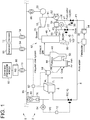
- FIG 1 is a schematic configuration diagram of the hydrogen production system 2 according to an embodiment.
- FIG 2 is a schematic configuration diagram of the hydrogen production system 2 according to an embodiment.
- FIG 3 is a schematic configuration diagram of the hydrogen production system 2 according to an embodiment.
- FIG 4 is a schematic configuration diagram of the hydrogen production system 2 according to an embodiment.
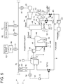
- FIG 5 is a schematic configuration diagram of the hydrogen production system 2 according to an embodiment.
- an electric power system 5, to which the hydrogen production system 2 is connected includes a generator 60 for generating power using depleting energy, such as thermal power generation and nuclear power generation, and a power generation device 62 for generating power using renewable energy, such as solar power generation and wind power generation.
- the amount of power generated using renewable energy may fluctuate depending on external environmental factors.
- the generator 60 is connected to a power grid 66 of the electric power system 5 via a transformer 64.
- the power generation device 62 is connected to the power grid 66 via a power conditioner (PCS: power conditioning system) 68 and a transformer 70.
- a power demander 72 is connected to the power grid 66 via a transformer 74.
- the hydrogen production system 2 includes a pure water production device 4, a hydrogen production device 6, a first pure water line 8, a first adjustment device 10, and a first control unit 12.
- the pure water production device 4 is configured to produce pure water by removing impurities from raw water.
- the hydrogen production device 6 is connected to the electric power system 5 via a substation 80 and is configured to produce hydrogen by electrolyzing pure water using power received from the electric power system 5.
- the substation 80 includes an AC/DC converter 76 and a transformer 78.
- the transformer 78 adjusts the voltage of AC power supplied from the electric power system 5, and the AC/DC converter 76 converts the AC power into DC power. Then, the DC power is supplied to the hydrogen production device 6.
- the hydrogen production system 2 includes an output control unit 82 capable of controlling the output of the hydrogen production device 6 according to request from the electric power system 5.
- the output control unit 82 controls the amount of power supplied from the electric power system 5 to the hydrogen production device 6 via the substation 80 according to request from the electric power system 5.
- the first pure water line 8 is configured to supply pure water produced by the pure water production device 4 to the hydrogen production device 6.
- the first adjustment device 10 is configured to adjust the amount of pure water supplied to the hydrogen production device 6 via the first pure water line 8.
- the first control unit 12 is configured to control the first adjustment device 10, based on a power amount signal V0 indicating information on the amount of power supplied from the electric power system 5 to the hydrogen production device 6.
- the first adjustment device 10 is a first valve 14 disposed in the first pure water line 8, and the first control unit 12 controls the opening degree of the valve 14 based on the power amount signal V0 to adjust the amount of pure water supplied to the hydrogen production device 6.
- the first control unit 12 controls the first adjustment device 10, based on the power amount signal V0 indicating information on the amount of power supplied from the electric power system 5 to the hydrogen production device 6.
- the hydrogen production system 2 includes a power meter 84 for measuring the amount of power supplied from the electric power system 5 to the hydrogen production device 6.
- the power amount signal V0 is an output signal of the power meter 84. That is, the first control unit 12 controls the first adjustment device 10, based on the output signal of the power meter 84.
- the power amount signal V0 is a control signal for controlling the output of the hydrogen production device 6 by the output control unit 82. That is, the first control unit 12 controls the first adjustment device 10 to adjust the amount of pure water supplied to the hydrogen production device 6, based on the control signal transmitted by the output control unit 82 for controlling the output of the hydrogen production device 6.
- the hydrogen production device 6 is connected to the power grid 66 via the substation 80 and is connected to the power generation device 62 using renewable energy via the power grid 66.
- power obtained from the power generation device 62 using renewable energy is converted into high-voltage AC power via the power conditioner 68 and the transformer 70, transmitted through the power grid 66, converted into low-voltage DC power via the substation 80, and then supplied to the hydrogen production device 6.
- the surplus power of the electric power system 5 can be supplied to the hydrogen production device 6 via the power grid 66 with a small transmission loss.
- the hydrogen production device 6 is directly connected to the power generation device 62 using renewable energy not via the power grid 66.
- power obtained from the power generation device 62 using renewable energy is converted into AC voltage via the power conditioner 68, transmitted through the power grid 67, converted into DC power via the substation 80, and then supplied to the hydrogen production device 6.
- the surplus power of the electric power system 5 can be directly supplied to the hydrogen production device 6 not via the high-voltage power grid 66 with a small transmission loss.
- the hydrogen production system 2 includes a steam cycle 92 including a boiler 22 and a steam turbine 18 driven by steam of the boiler 22, a generator 20 configured to be driven by the steam turbine 18, and a second pure water line 28 for supplying pure water produced by the pure water production device 4 to a position downstream of the steam turbine 18 and upstream of the boiler 22 in the steam cycle 92.
- the first pure water line 8 is connected to the second pure water line.
- one pure water production device can be used as the pure water production device 4 for producing pure water supplied to the hydrogen production device 6 and the pure water production device 4 for producing pure water supplied to the boiler 22.
- the facility configuration of the pure water production device can be simplified, and the facility cost and the operating cost can be reduced.
- the hydrogen production system 2 includes a pure water tank 30, disposed upstream of a connection position P1 between the second pure water line 28 and the first pure water line 8 and downstream of the pure water production device 4, for storing pure water produced by the pure water production device 4.
- one pure water tank can be used as the pure water tank 30 for supplying pure water to the hydrogen production device 6 and the pure water tank 30 for supplying pure water to the boiler 22.
- the facility configuration of the pure water tank can be simplified, and the facility cost and the operating cost can be reduced.
- the amount of pure water to be supplied to the hydrogen production device 6 and the amount of pure water to be supplied to the boiler 22 fluctuate, it is possible to flexibly respond to the fluctuation by discharging pure water stored in the pure water tank 30, and it is possible to simplify the facility configuration of the pure water production device 4.
- the boiler 22 includes a furnace 44 for combusting fuel and a heat exchanger 46 for producing steam by using exhaust gas discharged from the furnace 44.
- the boiler 22 is a circulating fluidized bed boiler.
- the furnace 44 is configured to combust coal as the fuel
- the boiler 22 includes a cyclone 48 for collecting particles contained in exhaust gas produced by the combustion in the furnace 44 and guided to the cyclone 48, and an external heat exchanger 50 for recovering thermal energy of the particles in the exhaust gas collected by the cyclone 48. From the bottom of the furnace 44, air is supplied to the inside of the furnace 44, and ash is discharged to the outside of the furnace 44.
- the steam produced by the heat exchanger 46 is supplied to the steam turbine 18 via a steam line 26, works in the steam turbine 18, and then is condensed by a condenser 52 through a condensate line 51 to form condensed water.
- the condensed water is, after passing through a water treatment device 54, boosted by a water supply pump 90 disposed in a water supply line 45, and is supplied to the heat exchanger 46 again.
- the heat exchanger 46, the steam line 26, the steam turbine 18, the condensate line 51, the condenser 52, the water treatment device 54, the water supply line 45, and the water supply pump 90 constitute the steam cycle 92.
- the exhaust gas that has undergone heat exchange in the heat exchanger 46 is purified and then discharged from a stack 56.
- the water treatment device 54 may perform combined water treatment (CWT) on feedwater, for example.
- the combined water treatment is a treatment in which oxygen is injected into feedwater to inactivate iron, and a protective film of hematite is formed on the surface of the base material of the system to prevent corrosion.
- oxygen produced by electrolysis of water in the hydrogen production device 6 may be used for the combined water treatment by the water treatment device 54.
- oxygen which is a by-product of the hydrogen production device 6 for the water treatment the cost for procuring oxygen can be reduced.
- the hydrogen production system 2 includes a hydrogen line 86 for supplying hydrogen produced by the hydrogen production device 6 to the furnace 44.
- a hydrogen line 86 for supplying hydrogen produced by the hydrogen production device 6 to the furnace 44.
- the hydrogen production system 2 includes a hydrogen storage device 58 disposed in the hydrogen line 86 so as to store hydrogen produced by the hydrogen production device 6.
- the generator 20 is connected to the power grid 66 of the electric power system 5 via a transformer 88.
- hydrogen produced by the hydrogen production device 6 using the surplus power of the electric power system 5 can be stored in the hydrogen storage device 58, and during the time when the amount of power generated in the electric power system 5 is insufficient with respect to the power demand, hydrogen can be supplied from the hydrogen storage device 58 to the furnace 44 to generate power by the generator 20 with the above method.
- This contributes to the stabilization of the electric power system and the effective use of renewable energy, resulting in a reduction in CO 2 emissions.
- Even during the time when surplus power is generated in the electric power system for example, if the power generation cost of fossil fuel is higher than the power generation cost of the generator 20 using hydrogen produced by the hydrogen production device 6, hydrogen may be used preferentially over fossil fuel to generate power.
- FIG 6 is a diagram showing an example of one-day transition of the power generation amount of the generator 20, 60, the power generation amount of the power generation device 62, and the power demand in some embodiments shown in FIGs. 1 and 3 to 5.
- the output control unit 82 performs control to supply the surplus power to the hydrogen production device 6 via the substation 80 to produce hydrogen and store the hydrogen in the hydrogen storage device 58, based on request from the electric power system 5.
- the output control unit 82 performs control to cause the hydrogen produced in the daytime and stored in the hydrogen storage device 58 to be released from the hydrogen storage device 58 at night and supplied to the furnace 44 together with coal.
- the energy of hydrogen produced and stored in the daytime using renewable energy can be used to generate power by the generator 20 at night. This contributes to the stabilization of the electric power system and the effective use of renewable energy, resulting in a reduction in CO 2 emissions.
- only hydrogen released from the hydrogen storage device 58 may be combusted as the fuel at night without using coal as the fuel.
- the hydrogen production system 2 does not include the hydrogen storage device 58, and hydrogen produced by the hydrogen production device 6 is supplied to the furnace 44 via the hydrogen line 86 without storing the hydrogen.
- the generator 20 is not connected to the power grid 66 of the electric power system 5 but functions as a private generator.
- the hydrogen production system 2 includes a second adjustment device 32 capable of adjusting the amount of pure water supplied to the boiler 22 via the second pure water line 28, and a second control unit 36 configured to control the second adjustment device 32, based on a first signal V1 indicating information on the amount of pure water supplied from the first pure water line 8 to the hydrogen production device 6.
- the second adjustment device 32 is a valve 38 disposed in the second pure water line 28, and the second control unit 36 controls the opening degree of the valve 38 based on the first signal V1 to adjust the amount of pure water supplied to the boiler 22.
- the hydrogen production system 2 includes a blow-down water line 34 for discharging blow-down water of the boiler 22, a blow-down water amount adjustment device 40 for adjusting the amount of blow-down water discharged from the blow-down water line 34, and a blow-down water control unit 42 configured to control the blow-down water amount adjustment device 40, based on a second signal V2 indicating information on the amount of pure water supplied from the first pure water line 8 to the hydrogen production device 6.
- the blow-down water amount adjustment device 40 is a valve 96 disposed in the blow-down water line 34, and the blow-down water control unit 42 controls the opening degree of the valve 96 based on the second signal V2 to adjust the amount of blow-down water discharged from the blow-down water line 34.
- the second signal V2 may be, for example, the power amount signal V0 described above, or may be a signal indicating a measurement value of the amount of pure water supplied from the first pure water line 8 to the hydrogen production device 6.
- the hydrogen production system 2 includes a water meter 25 for measuring the amount of blow-down water discharged from the blow-down water line 34.
- the first signal V1 may be an output signal of the water meter 25 or the power amount signal V0, or may be a signal indicating a measurement value of the amount of pure water supplied from the first pure water line 8 to the hydrogen production device 6.
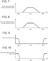
- FIG 7 is a diagram showing an example of one-day transition of the power supply amount to the hydrogen production device 6 in the embodiments shown in FIGs. 1 to 5 .
- FIG 8 is a diagram showing an example of one-day transition of the pure water supply amount to the hydrogen production device 6 corresponding to the one-day transition of the power supply amount shown in FIG 7.
- FIG 9 is a diagram showing an example of one-day transition of the blow-down water amount of the boiler 22 corresponding to the one-day transition of the power supply amount shown in FIG 7.
- FIG 10 is a diagram showing an example of one-day transition of the pure water supply amount to the steam cycle 92 corresponding to the one-day transition of the power supply amount shown in FIG 7 .
- the one-day transition of each amount shown in FIGs. 7 to 10 corresponds to the one-day transition of the power generation amount, etc., shown in FIG 6 .
- the second control unit 36 (see FIGs. 1 to 5 ) is configured to able to execute a limit mode which limits the amount of pure water supplied from the second pure water line 28 to the boiler 22 such that the supply of pure water to the hydrogen production device 6 is prioritized over the supply of pure water to the steam cycle 92.
- a limit mode which limits the amount of pure water supplied from the second pure water line 28 to the boiler 22 such that the supply of pure water to the hydrogen production device 6 is prioritized over the supply of pure water to the steam cycle 92.
- the second control unit 36 is configured to limit a period for supplying pure water to the steam cycle 92 to a period during which the supply of pure water to the hydrogen production device 6 is stopped or to a period during which the amount of pure water supplied to the hydrogen production device 6 is equal to or less than a reference amount.
- the hydrogen production system 2 includes a remaining amount detection unit 94 for detecting the remaining amount of the pure water tank 30, and the second control unit 36 is configured to, when the remaining amount of the pure water tank 30 detected by the remaining amount detection unit 94 exceeds a reference value, not execute the limit mode, and when the remaining amount of the pure water tank 30 detected by the remaining amount detection unit 94 falls below the reference value, execute the limit mode.
- the remaining amount detection unit 94 may be, for example, a water level meter.
- the amount of pure water that can be supplied to the hydrogen production device 6 and the boiler 22 is small as compared with the case where the pure water tank 30 has a sufficient remaining amount of pure water. Accordingly, as described above, if the limit mode is not executed when the remaining amount of the pure water tank 30 exceeds the reference value while the limit mode is executed when the remaining amount falls below the reference value, it is possible to absorb the surplus power of the electric power system while efficiently producing hydrogen by the hydrogen production device and generating power by the generator.
- FIG 11 is a diagram showing a hardware configuration of each of the output control unit 82, the first control unit 12, the second control unit 36, and the blow-down water control unit 42. Since the outlines of the hardware configurations of the respective control units are the same, the same reference numerals are used in FIG 11 for convenience.
- Each control unit is implemented by a computer including a central processing unit (CPU) 98, a random access memory (RAM) 100, a read only memory (ROM) 102, a hard disk drive (HDD) 104, an input I/F 106, and an output I/F 108, which are connected via a bus 110.
- the hardware configuration of each control unit is limited thereto, and may be configured by a combination of a control circuit and a storage device.
- each control unit is implemented by executing a program that realizes each function of the control unit by the computer.
- the function of each control unit described below is realized by, for instance, loading a program stored in the ROM 102 into the RAM 100 and executing the program by the CPU 98, and reading and writing data in the RAM 100 or the ROM 102.
- the present invention is not limited to the embodiments described above, but includes modifications to the embodiments described above, and embodiments composed of combinations of those embodiments.
- the circulating fluidized bed boiler including the furnace 44 and the heat exchanger 46 has been described as an example of the means for producing steam.
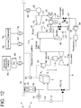
- the means for producing steam is not limited to the above-described embodiments, and may be, for example, a pulverized coal-fired boiler, a natural gas-fired boiler, or a heavy crude oil-fired boiler, or may be a combination of a gas turbine 112 and a heat recovery steam generator 114 (HRSG) in a gas turbine combined cycle (GTCC) as shown in FIG 12 .
- HRSG heat recovery steam generator 114
- GTCC gas turbine combined cycle
- hydrogen produced by the hydrogen production device 6 is supplied to the gas turbine 112 via the hydrogen storage device 58, mixed with natural gas, and combusted by a combustor 113 of the gas turbine 112. Further, feedwater supplied to the heat recovery steam generator 114 via the water supply line 45 evaporates due to exhaust heat of the gas turbine 112 in the heat recovery steam generator 114 to form steam, and is supplied to the steam turbine 18.
- the second pure water line 28 is configured to supply pure water to a position downstream of the steam turbine 18 and upstream of the heat recovery steam generator 114 in a steam cycle 116 including the heat recovery steam generator 114 and the steam turbine 18 driven by steam of the heat recovery steam generator 114.
- the combustor 113 of the gas turbine 112 only hydrogen produced by the hydrogen production device 6 may be combusted as the fuel without using natural gas as the fuel.
Landscapes
- Engineering & Computer Science (AREA)
- Chemical & Material Sciences (AREA)
- Combustion & Propulsion (AREA)
- General Engineering & Computer Science (AREA)
- Mechanical Engineering (AREA)
- Materials Engineering (AREA)
- Organic Chemistry (AREA)
- Electrochemistry (AREA)
- Chemical Kinetics & Catalysis (AREA)
- Metallurgy (AREA)
- Inorganic Chemistry (AREA)
- Life Sciences & Earth Sciences (AREA)
- Sustainable Development (AREA)
- Sustainable Energy (AREA)
- Physics & Mathematics (AREA)
- Thermal Sciences (AREA)
- Automation & Control Theory (AREA)
- Power Engineering (AREA)
- Electrolytic Production Of Non-Metals, Compounds, Apparatuses Therefor (AREA)
- Supply And Distribution Of Alternating Current (AREA)
Abstract
Description
- The present disclosure relates to a hydrogen production system.
-
Patent Document 1 discloses a hydrogen production system that produces hydrogen by using the exhaust heat of an incinerator that incinerates waste. The hydrogen production system ofPatent Document 1 includes an incinerator for incinerating waste, a pure water production device for producing pure water from raw water, a boiler for recovering heat of exhaust gas discharged from the incinerator and heating the pure water produced by the pure water production device to produce steam, a generator for generating power by using the steam, a water electrolysis device for electrolyzing the pure water produced by the pure water production device by using the power generated by the generator to produce hydrogen and oxygen, a hydrogen tank for storing the hydrogen, and an oxygen tank for storing the oxygen. - Patent Document 1:
JP2017-89916A - If the balance between supply and demand of electric power is lost due to the introduction of renewable energy or fluctuations in power demand in an electric power system, surplus power is generated, and the power is wasted.
- In this regard, in the hydrogen production system disclosed in
Patent Document 1, the surplus power of the electric power system is not absorbed although the generator is driven by steam produced using exhaust gas of the incinerator in the system and hydrogen is produced using power obtained from the generator. - At least one embodiment of the present invention was made in view of the above typical problem, and an object thereof is to provide a hydrogen production system that can absorb the surplus power of the electric power system.
-
- (1) A hydrogen production system according at least one embodiment of the present invention comprises: a hydrogen production device connected to an electric power system and configured to produce hydrogen by electrolyzing pure water; an output control unit capable of controlling an amount of power supplied from the electric power system to the hydrogen production device according to request from the electric power system; a first pure water line for supplying pure water to the hydrogen production device; a first adjustment device capable of adjusting an amount of pure water supplied to the hydrogen production device via the first pure water line; and a first control unit configured to control the first adjustment device, based on a power amount signal indicating information on an amount of power supplied from the electric power system to the hydrogen production device.
With the above configuration (1), when surplus power is generated due to fluctuations in output of renewable energy or fluctuations in power demand in the electric power system, the surplus power of the electric power system is received by the hydrogen production device based on request from the electric power system, and the surplus electric power is used to electrolyze pure water to produce hydrogen.
Here, the amount of surplus power in the electric power system changes with fluctuations in output of renewable energy or fluctuations in power demand, etc. In this regard, in the above configuration (1), the first control unit controls the first adjustment device based on the power amount signal indicating information on the amount of power supplied from the electric power system to the hydrogen production device to adjust the amount of pure water supplied to the hydrogen production device.
Thus, since an appropriate amount of pure water is supplied to the hydrogen production device according to the amount of power supplied from the electric power system to the hydrogen production device, hydrogen can be efficiently produced by exhibiting the performance of the hydrogen production device while absorbing the surplus power of the electric power system. This contributes to the stabilization of the electric power system and the operation with less waste of electric power derived from renewable energy. Further, the use of power derived from renewable energy to produce hydrogen results in a reduction in CO2 emissions. - (2) In some embodiments, in the above configuration (1), the hydrogen production system further comprises a power meter for measuring an amount of power supplied from the electric power system to the hydrogen production device. The power amount signal is an output signal of the power meter. The first control unit is configured to control the first adjustment device based on the output signal of the power meter.
With the above configuration (2), since the amount of pure water supplied from the first pure water line to the hydrogen production device is adjusted according to the amount of power supplied to the hydrogen production device as measured by the power meter, it is possible to supply an appropriate amount of pure water to the hydrogen production device according to the amount of power actually supplied from the electric power system to the hydrogen production device. Accordingly, hydrogen can be efficiently produced by effectively exhibiting the performance of the hydrogen production device. - (3) In some embodiments, in the above configuration (1), the power amount signal is a control signal by which the output control unit controls an amount of power supplied to the hydrogen production device. The first control unit is configured to control the first adjustment device based on the control signal of the output control unit.
With the above configuration (3), without using the power meter, it is possible to supply an appropriate amount of pure water to the hydrogen production device according to the amount of power supplied from the electric power system to the hydrogen production device. Accordingly, hydrogen can be efficiently produced by exhibiting the performance of the hydrogen production device with a simple configuration. - (4) In some embodiments, in any one of the above configurations (1) to (3), the first pure water line is connected to a second pure water line for supplying pure water to a steam cycle including a boiler and a steam turbine driven by steam of the boiler at a position downstream of the steam turbine and upstream of the boiler.
With the above configuration (4), one pure water production device can be used as the pure water production device for producing pure water supplied to the hydrogen production device and the pure water production device for producing pure water supplied to the boiler. As a result, compared with the case where the pure water production device for producing pure water supplied to the boiler and the pure water production device for producing pure water supplied to the hydrogen production device are separately provided, the facility configuration of the pure water production device can be simplified, and the facility cost and the operating cost can be reduced. - (5) In some embodiments, in the above configuration (4), the hydrogen production system further comprises a hydrogen line for supplying hydrogen produced by the hydrogen production device to the boiler.
With the above configuration (5), since the fuel mixed with hydrogen can be combusted in the boiler, it is possible to produce steam in the boiler by using hydrogen produced by the hydrogen production device and generate power by the generator connected to the steam turbine. - (6) In some embodiments, in the above configuration (5), the hydrogen production system further comprises a hydrogen storage device for storing hydrogen produced by the hydrogen production device, and a generator driven by the steam turbine is connected to the electric power system.
With the above configuration (6), hydrogen produced by the hydrogen production device using the surplus power of the electric power system can be stored in the hydrogen storage device, and during the time when the surplus power is not generated in the electric power system, hydrogen can be supplied from the hydrogen storage device to the boiler to generate power by the generator with the above method. This contributes to the stabilization of the electric power system and the effective use of renewable energy, resulting in a reduction in CO2 emissions. - (7) In some embodiments, in any one of the above configurations (4) to (6), the hydrogen production system further comprises: a pure water production device configured to produce pure water by removing an impurity from raw water to supply pure water to the second pure water line; and a pure water tank for storing pure water produced by the pure water production device and disposed upstream of a connection position between the second pure water line and the first pure water line and downstream of the pure water production device.
With the above configuration (7), one pure water tank can be used as the pure water tank for supplying pure water to the hydrogen production device and the pure water tank for supplying pure water to the boiler. As a result, compared with the case where the pure water tank for supplying pure water to the boiler and the pure water tank for supplying pure water to the hydrogen production device are separately provided, the facility configuration of the pure water tank can be simplified, and the facility cost and the operating cost can be reduced. Further, even when the amount of pure water to be supplied to the hydrogen production device and the amount of pure water to be supplied to the boiler fluctuate, it is possible to flexibly respond to the fluctuation by discharging pure water stored in the pure water tank, and it is possible to simplify the facility configuration of the pure water production device. - (8) In some embodiments, in any one of the above configurations (4) to (6), the hydrogen production system further comprises: a second adjustment device capable of adjusting an amount of pure water supplied to the boiler via the second pure water line; and a second control unit configured to control the second adjustment device, based on a first signal indicating information on an amount of pure water supplied from the first pure water line to the hydrogen production device.
With the above configuration (8), the amount of pure water supplied to the boiler via the second pure water line can be appropriately adjusted in consideration of the amount of pure water supplied from the first pure water line to the hydrogen production device. - (9) In some embodiments, in the above configuration (8), the second control unit is configured to be able to execute a limit mode which limits an amount of pure water supplied from the second pure water line to the boiler such that supply of pure water to the hydrogen production device is prioritized over supply of pure water to the steam cycle.
With the above configuration (9), it is possible to effectively absorb the surplus power of the electric power system while generating power by the generator via the steam turbine to the extent possible. - (10) In some embodiments, in the above configuration (9), in the limit mode, the second control unit is configured to limit a period for supplying pure water to the steam cycle to a period during which supply of pure water to the hydrogen production device is stopped or to a period during which an amount of pure water supplied to the hydrogen production device is equal to or less than a reference amount.
With the above configuration (10), it is possible to avoid overlapping between the period for supplying pure water to the hydrogen production device and the period for supplying pure water to the steam cycle. Accordingly, it is possible to suppress an increase in the installation volume of the pure water production device and the pure water tank, and it is possible to reduce the facility cost and the operating cost of the hydrogen production system. In addition, it is possible to absorb the surplus power of the electric power system. - (11) In some embodiments, in the above configuration (9) or (10), the hydrogen production system further comprises: a pure water tank for storing pure water produced by a pure water production device; and a remaining amount detection unit for detecting a remaining amount of the pure water tank. The second control unit is configured to execute the limit mode when the remaining amount detected by the remaining amount detection unit falls below a reference value.
When the remaining amount of the pure water tank is small, the amount of pure water that can be supplied to the hydrogen production device and the boiler is small as compared with the case where the pure water tank has a sufficient remaining amount of pure water. Accordingly, as described in (9) or (10), if the limit mode is not executed when the remaining amount of the pure water tank exceeds the reference value while the limit mode is executed when the remaining amount falls below the reference value, it is possible to absorb the surplus power of the electric power system while efficiently producing hydrogen by the hydrogen production device and generating power by the generator. - (12) In some embodiments, in any one of the above configurations (8) to (11), the hydrogen production system further comprises: a blow-down water line for discharging blow-down water of the boiler; a blow-down water amount adjustment device for adjusting an amount of blow-down water discharged from the blow-down water line; and a blow-down water control unit configured to control the blow-down water amount adjustment device, based on a second signal indicating information on an amount of pure water supplied from the first pure water line to the hydrogen production device.
With the above configuration (12), the amount of blow-down water discharged from the blow-down water line can be appropriately adjusted in consideration of the amount of pure water supplied from the first pure water line to the hydrogen production device. - (13) In some embodiments, in the above configuration (12), the hydrogen production system further comprises a water meter for measuring an amount of the blow-down water discharged from the blow-down water line. The first signal is an output signal of the water meter. The second control unit is configured to control the second adjustment device based on the output signal of the water meter.
- With the above configuration (13), an appropriate amount of pure water can be supplied to the boiler according to the amount of blow-down water discharged from the blow-down water line. Thus, it is possible to appropriately maintain the amount of pure water necessary for the steam cycle.
- At least one embodiment of the present invention provides a hydrogen production system that can absorb the surplus power of the power grid.
-
-
FIG 1 is a schematic configuration diagram of ahydrogen production system 2 according to an embodiment. -
FIG 2 is a schematic configuration diagram of ahydrogen production system 2 according to an embodiment. -
FIG 3 is a schematic configuration diagram of ahydrogen production system 2 according to an embodiment. -
FIG 4 is a schematic configuration diagram of ahydrogen production system 2 according to an embodiment. -
FIG 5 is a schematic configuration diagram of ahydrogen production system 2 according to an embodiment. -
FIG 6 is a diagram showing an example of one-day transition of the power generation amount of agenerator power generation device 62, and the power demand in some embodiments shown inFIGs. 1 and3 to 5 . -
FIG 7 is a diagram showing an example of one-day transition of the power supply amount to ahydrogen production device 6 in some embodiments shown inFIGs. 1 to 5 . -
FIG 8 is a diagram showing an example of one-day transition of the pure water supply amount to thehydrogen production device 6 corresponding to the one-day transition of the power supply amount shown inFIG 7 . -
FIG 9 is a diagram showing an example of one-day transition of the blow-down water amount of aboiler 22 corresponding to the one-day transition of the power supply amount shown inFIG 7 . -
FIG 10 is a diagram showing an example of one-day transition of the pure water supply amount to asteam cycle 92 corresponding to the one-day transition of the power supply amount shown inFIG 7 . -
FIG 11 is a diagram showing a hardware configuration of each of anoutput control unit 82, afirst control unit 12, asecond control unit 36, and a blow-downwater control unit 42. -
FIG 12 is a schematic configuration diagram of ahydrogen production system 2 according to an embodiment. - Embodiments of the present invention will now be described in detail with reference to the accompanying drawings. It is intended, however, that unless particularly identified, dimensions, materials, shapes, relative positions, and the like of components described in the embodiments shall be interpreted as illustrative only and not intended to limit the scope of the present invention.
- For instance, an expression of relative or absolute arrangement such as "in a direction", "along a direction", "parallel", "orthogonal", "centered", "concentric" and "coaxial" shall not be construed as indicating only the arrangement in a strict literal sense, but also includes a state where the arrangement is relatively displaced by a tolerance, or by an angle or a distance whereby it is possible to achieve the same function.
- For instance, an expression of an equal state such as "same" "equal" and "uniform" shall not be construed as indicating only the state in which the feature is strictly equal, but also includes a state in which there is a tolerance or a difference that can still achieve the same function.
- Further, for instance, an expression of a shape such as a rectangular shape or a cylindrical shape shall not be construed as only the geometrically strict shape, but also includes a shape with unevenness or chamfered corners within the range in which the same effect can be achieved.
- On the other hand, an expression such as "comprise", "include", "have", "contain" and "constitute" are not intended to be exclusive of other components.
-
FIG 1 is a schematic configuration diagram of thehydrogen production system 2 according to an embodiment.FIG 2 is a schematic configuration diagram of thehydrogen production system 2 according to an embodiment.FIG 3 is a schematic configuration diagram of thehydrogen production system 2 according to an embodiment.FIG 4 is a schematic configuration diagram of thehydrogen production system 2 according to an embodiment.FIG 5 is a schematic configuration diagram of thehydrogen production system 2 according to an embodiment. - In some embodiments, an
electric power system 5, to which thehydrogen production system 2 is connected, includes agenerator 60 for generating power using depleting energy, such as thermal power generation and nuclear power generation, and apower generation device 62 for generating power using renewable energy, such as solar power generation and wind power generation. The amount of power generated using renewable energy may fluctuate depending on external environmental factors. Thegenerator 60 is connected to apower grid 66 of theelectric power system 5 via atransformer 64. Thepower generation device 62 is connected to thepower grid 66 via a power conditioner (PCS: power conditioning system) 68 and atransformer 70. Apower demander 72 is connected to thepower grid 66 via atransformer 74. - In some embodiments, for example as shown in
FIGs. 1 to 5 , thehydrogen production system 2 includes a purewater production device 4, ahydrogen production device 6, a firstpure water line 8, afirst adjustment device 10, and afirst control unit 12. - The pure
water production device 4 is configured to produce pure water by removing impurities from raw water. Thehydrogen production device 6 is connected to theelectric power system 5 via asubstation 80 and is configured to produce hydrogen by electrolyzing pure water using power received from theelectric power system 5. Thesubstation 80 includes an AC/DC converter 76 and atransformer 78. Thetransformer 78 adjusts the voltage of AC power supplied from theelectric power system 5, and the AC/DC converter 76 converts the AC power into DC power. Then, the DC power is supplied to thehydrogen production device 6. In the illustrated embodiment, thehydrogen production system 2 includes anoutput control unit 82 capable of controlling the output of thehydrogen production device 6 according to request from theelectric power system 5. Theoutput control unit 82 controls the amount of power supplied from theelectric power system 5 to thehydrogen production device 6 via thesubstation 80 according to request from theelectric power system 5. - The first
pure water line 8 is configured to supply pure water produced by the purewater production device 4 to thehydrogen production device 6. Thefirst adjustment device 10 is configured to adjust the amount of pure water supplied to thehydrogen production device 6 via the firstpure water line 8. Thefirst control unit 12 is configured to control thefirst adjustment device 10, based on a power amount signal V0 indicating information on the amount of power supplied from theelectric power system 5 to thehydrogen production device 6. In the illustrated embodiment, thefirst adjustment device 10 is afirst valve 14 disposed in the firstpure water line 8, and thefirst control unit 12 controls the opening degree of thevalve 14 based on the power amount signal V0 to adjust the amount of pure water supplied to thehydrogen production device 6. - With this configuration, when surplus power is generated due to fluctuations in output of renewable energy or fluctuations in power demand in the
electric power system 5, the surplus power of theelectric power system 5 is received by thehydrogen production device 6 based on request from theelectric power system 5, and the surplus power is used to electrolyze pure water to produce hydrogen. - Here, the amount of surplus power in the
electric power system 5 changes with fluctuations in output of renewable energy or fluctuations in power demand, etc. In this regard, in thehydrogen production system 2, thefirst control unit 12 controls thefirst adjustment device 10, based on the power amount signal V0 indicating information on the amount of power supplied from theelectric power system 5 to thehydrogen production device 6. - Thus, since an appropriate amount of pure water is supplied to the
hydrogen production device 6 according to the amount of power supplied from theelectric power system 5 to thehydrogen production device 6, hydrogen can be efficiently produced by exhibiting the performance of thehydrogen production device 6 while absorbing the surplus power of theelectric power system 5. This contributes to the stabilization of theelectric power system 5 and the operation with less waste of electric power derived from renewable energy. Further, the use of power derived from renewable energy to produce hydrogen results in a reduction in CO2 emissions. - In some embodiments, for example as shown in
FIGs. 1 to 3 and5 , thehydrogen production system 2 includes apower meter 84 for measuring the amount of power supplied from theelectric power system 5 to thehydrogen production device 6. In this case, the power amount signal V0 is an output signal of thepower meter 84. That is, thefirst control unit 12 controls thefirst adjustment device 10, based on the output signal of thepower meter 84. - With this configuration, since the amount of pure water supplied from the first
pure water line 8 to thehydrogen production device 6 is adjusted according to the amount of power supplied to thehydrogen production device 6 as measured by thepower meter 84, it is possible to supply an appropriate amount of pure water to thehydrogen production device 6 according to the amount of power actually supplied from theelectric power system 5 to thehydrogen production device 6. Accordingly, hydrogen can be efficiently produced by effectively exhibiting the performance of thehydrogen production device 6. - In some embodiments, for example as shown in
FIG 4 , the power amount signal V0 is a control signal for controlling the output of thehydrogen production device 6 by theoutput control unit 82. That is, thefirst control unit 12 controls thefirst adjustment device 10 to adjust the amount of pure water supplied to thehydrogen production device 6, based on the control signal transmitted by theoutput control unit 82 for controlling the output of thehydrogen production device 6. - With this configuration, without using the
power meter 84, it is possible to supply an appropriate amount of pure water to thehydrogen production device 6 according to the amount of power supplied from theelectric power system 5 to thehydrogen production device 6. Accordingly, hydrogen can be efficiently produced by exhibiting the performance of thehydrogen production device 6 with a simple configuration. - In some embodiments, for example as shown in
FIGs. 1 ,2 ,4 , and5 , thehydrogen production device 6 is connected to thepower grid 66 via thesubstation 80 and is connected to thepower generation device 62 using renewable energy via thepower grid 66. In this case, power obtained from thepower generation device 62 using renewable energy is converted into high-voltage AC power via thepower conditioner 68 and thetransformer 70, transmitted through thepower grid 66, converted into low-voltage DC power via thesubstation 80, and then supplied to thehydrogen production device 6. As a result, the surplus power of theelectric power system 5 can be supplied to thehydrogen production device 6 via thepower grid 66 with a small transmission loss. - In some embodiments, for example as shown in
FIG 3 , thehydrogen production device 6 is directly connected to thepower generation device 62 using renewable energy not via thepower grid 66. In this case, power obtained from thepower generation device 62 using renewable energy is converted into AC voltage via thepower conditioner 68, transmitted through thepower grid 67, converted into DC power via thesubstation 80, and then supplied to thehydrogen production device 6. As a result, the surplus power of theelectric power system 5 can be directly supplied to thehydrogen production device 6 not via the high-voltage power grid 66 with a small transmission loss. - In some embodiments, for example as shown in
FIGs. 1 to 5 , thehydrogen production system 2 includes asteam cycle 92 including aboiler 22 and asteam turbine 18 driven by steam of theboiler 22, agenerator 20 configured to be driven by thesteam turbine 18, and a secondpure water line 28 for supplying pure water produced by the purewater production device 4 to a position downstream of thesteam turbine 18 and upstream of theboiler 22 in thesteam cycle 92. The firstpure water line 8 is connected to the second pure water line. - With this configuration, in the case where the
hydrogen production device 6 for producing hydrogen and theboiler 22 for driving thesteam turbine 18 connected to thegenerator 20 are included, one pure water production device can be used as the purewater production device 4 for producing pure water supplied to thehydrogen production device 6 and the purewater production device 4 for producing pure water supplied to theboiler 22. As a result, compared with the case where the pure water production device for producing pure water supplied to theboiler 22 and the pure water production device for producing pure water supplied to thehydrogen production device 6 are separately provided, the facility configuration of the pure water production device can be simplified, and the facility cost and the operating cost can be reduced. - In some embodiments, for example as shown in
FIGs. 1 to 5 , thehydrogen production system 2 includes apure water tank 30, disposed upstream of a connection position P1 between the secondpure water line 28 and the firstpure water line 8 and downstream of the purewater production device 4, for storing pure water produced by the purewater production device 4. - With this configuration, one pure water tank can be used as the
pure water tank 30 for supplying pure water to thehydrogen production device 6 and thepure water tank 30 for supplying pure water to theboiler 22. As a result, compared with the case where the pure water tank for supplying pure water to theboiler 22 and the pure water tank for supplying pure water to thehydrogen production device 6 are separately provided, the facility configuration of the pure water tank can be simplified, and the facility cost and the operating cost can be reduced. Further, even when the amount of pure water to be supplied to thehydrogen production device 6 and the amount of pure water to be supplied to theboiler 22 fluctuate, it is possible to flexibly respond to the fluctuation by discharging pure water stored in thepure water tank 30, and it is possible to simplify the facility configuration of the purewater production device 4. - In some embodiments, for example as shown in
FIGs. 1 to 5 , theboiler 22 includes afurnace 44 for combusting fuel and aheat exchanger 46 for producing steam by using exhaust gas discharged from thefurnace 44. In the illustrated exemplary embodiment, theboiler 22 is a circulating fluidized bed boiler. Thefurnace 44 is configured to combust coal as the fuel, and theboiler 22 includes acyclone 48 for collecting particles contained in exhaust gas produced by the combustion in thefurnace 44 and guided to thecyclone 48, and anexternal heat exchanger 50 for recovering thermal energy of the particles in the exhaust gas collected by thecyclone 48. From the bottom of thefurnace 44, air is supplied to the inside of thefurnace 44, and ash is discharged to the outside of thefurnace 44. - The steam produced by the
heat exchanger 46 is supplied to thesteam turbine 18 via asteam line 26, works in thesteam turbine 18, and then is condensed by acondenser 52 through acondensate line 51 to form condensed water. The condensed water is, after passing through awater treatment device 54, boosted by awater supply pump 90 disposed in awater supply line 45, and is supplied to theheat exchanger 46 again. Thus, in the illustrated embodiment, theheat exchanger 46, thesteam line 26, thesteam turbine 18, thecondensate line 51, thecondenser 52, thewater treatment device 54, thewater supply line 45, and thewater supply pump 90 constitute thesteam cycle 92. The exhaust gas that has undergone heat exchange in theheat exchanger 46 is purified and then discharged from astack 56. - The
water treatment device 54 may perform combined water treatment (CWT) on feedwater, for example. The combined water treatment is a treatment in which oxygen is injected into feedwater to inactivate iron, and a protective film of hematite is formed on the surface of the base material of the system to prevent corrosion. In this case, as shown inFIG. 5 , oxygen produced by electrolysis of water in thehydrogen production device 6 may be used for the combined water treatment by thewater treatment device 54. Thus, by using oxygen which is a by-product of thehydrogen production device 6 for the water treatment, the cost for procuring oxygen can be reduced. - In some embodiments, for example as shown in
FIGs. 1 to 5 , thehydrogen production system 2 includes ahydrogen line 86 for supplying hydrogen produced by thehydrogen production device 6 to thefurnace 44. With this configuration, since the fuel (coal in the illustrated embodiment) mixed with hydrogen can be combusted in thefurnace 44, it is possible to produce steam in theboiler 22 by using hydrogen produced by thehydrogen production device 6 and generate power by thegenerator 20 connected to thesteam turbine 18. In another embodiment, in thefurnace 44, only hydrogen produced by thehydrogen production device 6 may be combusted as the fuel without using coal as the fuel. - In some embodiments, for example as shown in
FIGs. 1 and3 to 5 , thehydrogen production system 2 includes ahydrogen storage device 58 disposed in thehydrogen line 86 so as to store hydrogen produced by thehydrogen production device 6. In this case, thegenerator 20 is connected to thepower grid 66 of theelectric power system 5 via atransformer 88. - With this configuration, hydrogen produced by the
hydrogen production device 6 using the surplus power of theelectric power system 5 can be stored in thehydrogen storage device 58, and during the time when the amount of power generated in theelectric power system 5 is insufficient with respect to the power demand, hydrogen can be supplied from thehydrogen storage device 58 to thefurnace 44 to generate power by thegenerator 20 with the above method. This contributes to the stabilization of the electric power system and the effective use of renewable energy, resulting in a reduction in CO2 emissions. Even during the time when surplus power is generated in the electric power system, for example, if the power generation cost of fossil fuel is higher than the power generation cost of thegenerator 20 using hydrogen produced by thehydrogen production device 6, hydrogen may be used preferentially over fossil fuel to generate power. -
FIG 6 is a diagram showing an example of one-day transition of the power generation amount of thegenerator power generation device 62, and the power demand in some embodiments shown inFIGs. 1 and3 to 5. - As shown in
FIG 6 , in the daytime, the amount of power generated by thepower generation device 62 using renewable energy including solar power generation increases, so that the total amount of power generation increases and exceeds the power demand, and surplus power is likely to be generated. Therefore, in the daytime when the surplus power is generated, theoutput control unit 82 performs control to supply the surplus power to thehydrogen production device 6 via thesubstation 80 to produce hydrogen and store the hydrogen in thehydrogen storage device 58, based on request from theelectric power system 5. - At night when the output of solar power generation or the like is lost, power is generated by the
generator 60 mainly using depleting energy, such as thermal power generation. Theoutput control unit 82 performs control to cause the hydrogen produced in the daytime and stored in thehydrogen storage device 58 to be released from thehydrogen storage device 58 at night and supplied to thefurnace 44 together with coal. Thus, the energy of hydrogen produced and stored in the daytime using renewable energy can be used to generate power by thegenerator 20 at night. This contributes to the stabilization of the electric power system and the effective use of renewable energy, resulting in a reduction in CO2 emissions. In another embodiment, in thefurnace 44, only hydrogen released from thehydrogen storage device 58 may be combusted as the fuel at night without using coal as the fuel. - In some embodiments, for example as shown in
FIG 2 , thehydrogen production system 2 does not include thehydrogen storage device 58, and hydrogen produced by thehydrogen production device 6 is supplied to thefurnace 44 via thehydrogen line 86 without storing the hydrogen. In this case, thegenerator 20 is not connected to thepower grid 66 of theelectric power system 5 but functions as a private generator. - With this configuration, since the
generator 20 functions as a private generator which is not affected by the demand on theelectric power system 5, hydrogen produced by thehydrogen production device 6 can be used in real time without storing hydrogen. - In some embodiments, for example as shown in
FIGs. 1 to 5 , thehydrogen production system 2 includes asecond adjustment device 32 capable of adjusting the amount of pure water supplied to theboiler 22 via the secondpure water line 28, and asecond control unit 36 configured to control thesecond adjustment device 32, based on a first signal V1 indicating information on the amount of pure water supplied from the firstpure water line 8 to thehydrogen production device 6. In the illustrated embodiment, thesecond adjustment device 32 is avalve 38 disposed in the secondpure water line 28, and thesecond control unit 36 controls the opening degree of thevalve 38 based on the first signal V1 to adjust the amount of pure water supplied to theboiler 22. - In some embodiments, for example as shown in
FIGs. 1 to 5 , thehydrogen production system 2 includes a blow-downwater line 34 for discharging blow-down water of theboiler 22, a blow-down wateramount adjustment device 40 for adjusting the amount of blow-down water discharged from the blow-downwater line 34, and a blow-downwater control unit 42 configured to control the blow-down wateramount adjustment device 40, based on a second signal V2 indicating information on the amount of pure water supplied from the firstpure water line 8 to thehydrogen production device 6. - In the illustrated embodiment, the blow-down water
amount adjustment device 40 is avalve 96 disposed in the blow-downwater line 34, and the blow-downwater control unit 42 controls the opening degree of thevalve 96 based on the second signal V2 to adjust the amount of blow-down water discharged from the blow-downwater line 34. The second signal V2 may be, for example, the power amount signal V0 described above, or may be a signal indicating a measurement value of the amount of pure water supplied from the firstpure water line 8 to thehydrogen production device 6. - In some embodiments, for example as shown in
FIGs. 1 to 5 , thehydrogen production system 2 includes awater meter 25 for measuring the amount of blow-down water discharged from the blow-downwater line 34. The first signal V1 may be an output signal of thewater meter 25 or the power amount signal V0, or may be a signal indicating a measurement value of the amount of pure water supplied from the firstpure water line 8 to thehydrogen production device 6. - In the embodiments shown in
FIGs. 1 to 5 , control as shown inFIGs. 7 to 10 can be performed, for example.FIG 7 is a diagram showing an example of one-day transition of the power supply amount to thehydrogen production device 6 in the embodiments shown inFIGs. 1 to 5 .FIG 8 is a diagram showing an example of one-day transition of the pure water supply amount to thehydrogen production device 6 corresponding to the one-day transition of the power supply amount shown inFIG 7. FIG 9 is a diagram showing an example of one-day transition of the blow-down water amount of theboiler 22 corresponding to the one-day transition of the power supply amount shown inFIG 7. FIG 10 is a diagram showing an example of one-day transition of the pure water supply amount to thesteam cycle 92 corresponding to the one-day transition of the power supply amount shown inFIG 7 . The one-day transition of each amount shown inFIGs. 7 to 10 corresponds to the one-day transition of the power generation amount, etc., shown inFIG 6 . - As shown in
FIGs. 7 and 8 , in the daytime when the surplus power of theelectric power system 5 tends to increase, power and pure water are supplied to thehydrogen production device 6 so as to absorb the surplus power, while in the nighttime when the surplus power of theelectric power system 5 tends to decrease, the supply of power and pure water to thehydrogen production device 6 is stopped. - On the other hand, as shown in
FIGs. 9 and 10 , in the daytime when power and pure water are supplied to thehydrogen production device 6, the supply of pure water to thehydrogen production device 6 is prioritized over the supply of pure water to thesteam cycle 92, so that pure water is not supplied to thesteam cycle 92. Further, in the nighttime when the supply of power and pure water to thehydrogen production device 6 is stopped, blow-down water is discharged, and pure water is supplied to thesteam cycle 92. - As described above, the second control unit 36 (see
FIGs. 1 to 5 ) is configured to able to execute a limit mode which limits the amount of pure water supplied from the secondpure water line 28 to theboiler 22 such that the supply of pure water to thehydrogen production device 6 is prioritized over the supply of pure water to thesteam cycle 92. As a result, it is possible to effectively absorb the surplus power of theelectric power system 5 while generating power by thegenerator 20 via thesteam turbine 18 to the extent possible. - Further, in the limit mode, the
second control unit 36 is configured to limit a period for supplying pure water to thesteam cycle 92 to a period during which the supply of pure water to thehydrogen production device 6 is stopped or to a period during which the amount of pure water supplied to thehydrogen production device 6 is equal to or less than a reference amount. With this configuration, it is possible to avoid overlapping between the period for supplying pure water to thehydrogen production device 6 and the period for supplying pure water to thesteam cycle 92. Accordingly, it is possible to suppress an increase in the installation volume of the purewater production device 4 and thepure water tank 30, and it is possible to reduce the facility cost and the operating cost of thehydrogen production system 2. In addition, it is possible to absorb the surplus power of theelectric power system 5. Further, in atypical boiler 22, since the blow-down water of theboiler 22 is discharged, for example, only once a day, even when the supply of pure water to thehydrogen production device 6 is prioritized over the discharge of blow-down water of theboiler 22 and the supply of pure water to thesteam cycle 92, thesteam cycle 92 can be operated satisfactorily. - In some embodiments, for example as shown in
FIGs. 1 to 5 , thehydrogen production system 2 includes a remainingamount detection unit 94 for detecting the remaining amount of thepure water tank 30, and thesecond control unit 36 is configured to, when the remaining amount of thepure water tank 30 detected by the remainingamount detection unit 94 exceeds a reference value, not execute the limit mode, and when the remaining amount of thepure water tank 30 detected by the remainingamount detection unit 94 falls below the reference value, execute the limit mode. The remainingamount detection unit 94 may be, for example, a water level meter. - When the remaining amount of the
pure water tank 30 is small, the amount of pure water that can be supplied to thehydrogen production device 6 and theboiler 22 is small as compared with the case where thepure water tank 30 has a sufficient remaining amount of pure water. Accordingly, as described above, if the limit mode is not executed when the remaining amount of thepure water tank 30 exceeds the reference value while the limit mode is executed when the remaining amount falls below the reference value, it is possible to absorb the surplus power of the electric power system while efficiently producing hydrogen by the hydrogen production device and generating power by the generator. -
FIG 11 is a diagram showing a hardware configuration of each of theoutput control unit 82, thefirst control unit 12, thesecond control unit 36, and the blow-downwater control unit 42. Since the outlines of the hardware configurations of the respective control units are the same, the same reference numerals are used inFIG 11 for convenience. Each control unit is implemented by a computer including a central processing unit (CPU) 98, a random access memory (RAM) 100, a read only memory (ROM) 102, a hard disk drive (HDD) 104, an input I/F 106, and an output I/F 108, which are connected via abus 110. The hardware configuration of each control unit is limited thereto, and may be configured by a combination of a control circuit and a storage device. Further, each control unit is implemented by executing a program that realizes each function of the control unit by the computer. The function of each control unit described below is realized by, for instance, loading a program stored in theROM 102 into theRAM 100 and executing the program by theCPU 98, and reading and writing data in theRAM 100 or theROM 102. - The present invention is not limited to the embodiments described above, but includes modifications to the embodiments described above, and embodiments composed of combinations of those embodiments.
- For example, in the above-described embodiments, the circulating fluidized bed boiler including the
furnace 44 and theheat exchanger 46 has been described as an example of the means for producing steam. However, the means for producing steam is not limited to the above-described embodiments, and may be, for example, a pulverized coal-fired boiler, a natural gas-fired boiler, or a heavy crude oil-fired boiler, or may be a combination of agas turbine 112 and a heat recovery steam generator 114 (HRSG) in a gas turbine combined cycle (GTCC) as shown inFIG 12 . - In the embodiment shown in
FIG 12 , hydrogen produced by thehydrogen production device 6 is supplied to thegas turbine 112 via thehydrogen storage device 58, mixed with natural gas, and combusted by acombustor 113 of thegas turbine 112. Further, feedwater supplied to the heat recovery steam generator 114 via thewater supply line 45 evaporates due to exhaust heat of thegas turbine 112 in the heat recovery steam generator 114 to form steam, and is supplied to thesteam turbine 18. In this case, the secondpure water line 28 is configured to supply pure water to a position downstream of thesteam turbine 18 and upstream of the heat recovery steam generator 114 in asteam cycle 116 including the heat recovery steam generator 114 and thesteam turbine 18 driven by steam of the heat recovery steam generator 114. In another embodiment, in thecombustor 113 of thegas turbine 112, only hydrogen produced by thehydrogen production device 6 may be combusted as the fuel without using natural gas as the fuel. -
- 2
- Hydrogen production system
- 4
- Pure water production device
- 5
- Electric power system
- 6
- Hydrogen production device
- 8
- First pure water line
- 10
- First adjustment device
- 12
- First control unit
- 14
- First valve
- 18
- Steam turbine
- 20
- Generator
- 22
- Boiler
- 25
- Water meter
- 26
- Steam line
- 28
- Second pure water line
- 30
- Pure water tank
- 32
- Second adjustment device
- 34
- Blow-down water line
- 36
- Second control unit
- 38
- Second valve
- 40
- Blow-down water amount adjustment device
- 42
- Blow-down water control unit
- 44
- Furnace
- 45
- Water supply line
- 46
- Heat exchanger
- 48
- Cyclone
- 50
- External heat exchanger
- 51
- Condensate line
- 52
- Condenser
- 54
- Water treatment device
- 56
- Stack
- 58
- Hydrogen storage device
- 60
- Generator
- 62
- Power generation device
- 64, 70, 74, 78, 88
- Transformer
- 66
- Power grid
- 68
- Power conditioner
- 72
- Demander
- 76
- AC/DC converter
- 80
- Substation
- 82
- Output control unit
- 84
- Power meter
- 86
- Hydrogen line
- 90
- Water supply pump
- 92
- Steam cycle
- 94
- Remaining amount detection unit
- 96
- Valve
- 98
- CPU
- 100
- RAM
- 102
- ROM
- 104
- HDD
- 106
- Input I/F
- 108
- Output I/F
- 110
- Bus
- 112
- Gas turbine
- 113
- Combustor
- 114
- Heat recovery steam generator
- 116
- Steam cycle
Claims (13)
- A hydrogen production system, comprising:a hydrogen production device connected to an electric power system and configured to produce hydrogen by electrolyzing pure water;an output control unit capable of controlling an amount of power supplied from the electric power system to the hydrogen production device according to request from the electric power system;a first pure water line for supplying pure water to the hydrogen production device;a first adjustment device capable of adjusting an amount of pure water supplied to the hydrogen production device via the first pure water line; anda first control unit configured to control the first adjustment device, based on a power amount signal indicating information on an amount of power supplied from the electric power system to the hydrogen production device.
- The hydrogen production system according to claim 1, further comprising a power meter for measuring an amount of power supplied from the electric power system to the hydrogen production device,
wherein the power amount signal is an output signal of the power meter, and
wherein the first control unit is configured to control the first adjustment device based on the output signal of the power meter. - The hydrogen production system according to claim 1,
wherein the power amount signal is a control signal by which the output control unit controls an amount of power supplied to the hydrogen production device, and
wherein the first control unit is configured to control the first adjustment device based on the control signal of the output control unit. - The hydrogen production system according to any one of claims 1 to 3,
wherein the first pure water line is connected to a second pure water line for supplying pure water to a steam cycle including a boiler and a steam turbine driven by steam of the boiler at a position downstream of the steam turbine and upstream of the boiler. - The hydrogen production system according to claim 4, further comprising a hydrogen line for supplying hydrogen produced by the hydrogen production device to the boiler.
- The hydrogen production system according to claim 5, further comprising a hydrogen storage device for storing hydrogen produced by the hydrogen production device,
wherein a generator driven by the steam turbine is connected to the electric power system. - The hydrogen production system according to any one of claims 4 to 6, further comprising:a pure water production device configured to produce pure water by removing an impurity from raw water to supply pure water to the second pure water line; anda pure water tank for storing pure water produced by the pure water production device, the pure water tank being disposed upstream of a connection position between the second pure water line and the first pure water line and downstream of the pure water production device.
- The hydrogen production system according to any one of claims 4 to 6, further comprising:a second adjustment device capable of adjusting an amount of pure water supplied to the boiler via the second pure water line; anda second control unit configured to control the second adjustment device, based on a first signal indicating information on an amount of pure water supplied from the first pure water line to the hydrogen production device.
- The hydrogen production system according to claim 8,
wherein the second control unit is configured to be able to execute a limit mode which limits an amount of pure water supplied from the second pure water line to the boiler such that supply of pure water to the hydrogen production device is prioritized over supply of pure water to the steam cycle. - The hydrogen production system according to claim 9,
wherein, in the limit mode, the second control unit is configured to limit a period for supplying pure water to the steam cycle to a period during which supply of pure water to the hydrogen production device is stopped or to a period during which an amount of pure water supplied to the hydrogen production device is equal to or less than a reference amount. - The hydrogen production system according to claim 9 or 10, further comprising:a pure water tank for storing pure water produced by a pure water production device; anda remaining amount detection unit for detecting a remaining amount of the pure water tank,wherein the second control unit is configured to execute the limit mode when the remaining amount detected by the remaining amount detection unit falls below a reference value.
- The hydrogen production system according to any one of claims 8 to 11, further comprising:a blow-down water line for discharging blow-down water of the boiler;a blow-down water amount adjustment device for adjusting an amount of blow-down water discharged from the blow-down water line; anda blow-down water control unit configured to control the blow-down water amount adjustment device, based on a second signal indicating information on an amount of pure water supplied from the first pure water line to the hydrogen production device.
- The hydrogen production system according to claim 12, further comprising a water meter for measuring an amount of the blow-down water discharged from the blow-down water line,
wherein the first signal is an output signal of the water meter, and
wherein the second control unit is configured to control the second adjustment device based on the output signal of the water meter.
Applications Claiming Priority (2)
| Application Number | Priority Date | Filing Date | Title |
|---|---|---|---|
| JP2018167528A JP7104591B2 (en) | 2018-09-07 | 2018-09-07 | Hydrogen production system |
| PCT/JP2019/032563 WO2020050019A1 (en) | 2018-09-07 | 2019-08-21 | Hydrogen production system |
Publications (2)
| Publication Number | Publication Date |
|---|---|
| EP3831985A1 true EP3831985A1 (en) | 2021-06-09 |
| EP3831985A4 EP3831985A4 (en) | 2021-09-22 |
Family
ID=69722559
Family Applications (1)
| Application Number | Title | Priority Date | Filing Date |
|---|---|---|---|
| EP19857163.0A Pending EP3831985A4 (en) | 2018-09-07 | 2019-08-21 | HYDROGEN PRODUCTION SYSTEM |
Country Status (5)
| Country | Link |
|---|---|
| US (2) | US11421329B2 (en) |
| EP (1) | EP3831985A4 (en) |
| JP (1) | JP7104591B2 (en) |
| CN (1) | CN112639170B (en) |
| WO (1) | WO2020050019A1 (en) |
Families Citing this family (10)
| Publication number | Priority date | Publication date | Assignee | Title |
|---|---|---|---|---|
| JP7104591B2 (en) * | 2018-09-07 | 2022-07-21 | 三菱重工業株式会社 | Hydrogen production system |
| US11670960B2 (en) | 2020-09-01 | 2023-06-06 | Mitsubishi Power Americas, Inc. | Integrated power production and storage systems |
| EP3967654A1 (en) * | 2020-09-11 | 2022-03-16 | L'air Liquide, Société Anonyme Pour L'Étude Et L'exploitation Des Procédés Georges Claude | Method and system for the production of hydrogen through steam reforming and high temperature electrolysis |
| JP7754665B2 (en) * | 2020-09-28 | 2025-10-15 | 一般財団法人電力中央研究所 | Power generation system |
| IT202100004421A1 (en) * | 2021-02-25 | 2022-08-25 | Nuovo Pignone Tecnologie Srl | POWER PLANT FOR THE GENERATION OF ELECTRICITY FOR AN ELECTRICITY NETWORK INCLUDING AN ELECTROLYZER SUPPLIED FROM THE ELECTRICITY NETWORK |
| CN113122879B (en) * | 2021-04-16 | 2022-09-13 | 阳光新能源开发股份有限公司 | Hydrogen production control method and hydrogen production system |
| JP6940713B1 (en) * | 2021-05-18 | 2021-09-29 | 三菱重工環境・化学エンジニアリング株式会社 | Hydrogen production system |
| CN113374537A (en) * | 2021-06-07 | 2021-09-10 | 西安热工研究院有限公司 | System for realizing upgrading and reconstruction of green hydrogen fuel with zero carbon emission of active thermal power generating unit |
| JP7822387B2 (en) * | 2021-07-29 | 2026-03-02 | 住友重機械工業株式会社 | Combustion device and combustion method |
| JP7790489B1 (en) | 2024-08-01 | 2025-12-23 | 三浦工業株式会社 | Hydrogen boiler and control device |
Family Cites Families (22)
| Publication number | Priority date | Publication date | Assignee | Title |
|---|---|---|---|---|
| US3459953A (en) * | 1967-03-20 | 1969-08-05 | Univ Oklahoma State | Energy storage system |
| JPS5016972B1 (en) | 1970-05-04 | 1975-06-17 | ||
| JP2002095167A (en) | 2000-09-14 | 2002-03-29 | Matsushita Electric Ind Co Ltd | Surplus power storage and supply device |
| DE10207791B4 (en) * | 2002-02-25 | 2010-04-01 | Rwe Power Ag | Method for using the primary control power provided in a thermal power plant to adapt to grid fluctuations |
| JP4034586B2 (en) * | 2002-03-29 | 2008-01-16 | 福田金属箔粉工業株式会社 | Copper foil for printed wiring board and method for producing the same |
| EP1396558A1 (en) * | 2002-05-10 | 2004-03-10 | Proton Energy Systems, Inc. | Anode/cathode feed high pressure electrolysis system |
| WO2005078159A1 (en) * | 2004-02-18 | 2005-08-25 | Ebara Corporation | Method and apparatus for producing hydrogen |
| US7000395B2 (en) * | 2004-03-11 | 2006-02-21 | Yuan Ze University | Hybrid clean-energy power-supply framework |
| US7340893B1 (en) * | 2004-05-14 | 2008-03-11 | Rowan James A | Steam generator system |
| US7188478B2 (en) | 2004-09-13 | 2007-03-13 | General Electric Company | Power generation system and method of operating same |
| FR2879854B1 (en) * | 2004-12-21 | 2008-05-30 | Inst Francais Du Petrole | METHOD OF MANAGING THE PRODUCTION OF ELECTRIC ENERGY |
| JP5016972B2 (en) | 2007-05-17 | 2012-09-05 | 株式会社日立製作所 | Heavy oil reforming method and heavy oil reforming combined plant |
| US20110011110A1 (en) * | 2009-07-03 | 2011-01-20 | Wilfrid John Hanson | Method and apparatus for generating and distributing electricity |
| JP6191070B2 (en) * | 2012-05-25 | 2017-09-06 | 三菱重工環境・化学エンジニアリング株式会社 | Ammonia treatment system |
| AU2014209146B2 (en) * | 2013-01-24 | 2017-08-24 | Edward HINDERS | Combined brayton/rankine cycle gas and steam turbine generating system operated in two closed loops |
| US10436074B2 (en) * | 2013-01-24 | 2019-10-08 | Tascosa Advanced Service, Inc. | Combined brayton/rankine cycle gas and steam turbine generating system operated in two closed loops |
| KR102225779B1 (en) * | 2013-07-09 | 2021-03-11 | 미츠비시 히타치 파워 시스템스 유럽 게엠베하 | Flexibly operable power plant and method for the operation thereof |
| JP6587460B2 (en) | 2015-08-31 | 2019-10-09 | 関西電力株式会社 | Hydrogen production facility and hydrogen production method |
| JP6613822B2 (en) | 2015-11-04 | 2019-12-04 | Jfeエンジニアリング株式会社 | Waste incineration and hydrogen production equipment and method |
| JP6553523B2 (en) | 2016-02-02 | 2019-07-31 | 株式会社日立製作所 | Power supply system |
| JP7104591B2 (en) * | 2018-09-07 | 2022-07-21 | 三菱重工業株式会社 | Hydrogen production system |
| US11670960B2 (en) * | 2020-09-01 | 2023-06-06 | Mitsubishi Power Americas, Inc. | Integrated power production and storage systems |
-
2018
- 2018-09-07 JP JP2018167528A patent/JP7104591B2/en active Active
-
2019
- 2019-08-21 EP EP19857163.0A patent/EP3831985A4/en active Pending
- 2019-08-21 WO PCT/JP2019/032563 patent/WO2020050019A1/en not_active Ceased
- 2019-08-21 US US17/272,835 patent/US11421329B2/en active Active
- 2019-08-21 CN CN201980057306.1A patent/CN112639170B/en active Active
-
2022
- 2022-07-18 US US17/867,265 patent/US11802344B2/en active Active
Also Published As
| Publication number | Publication date |
|---|---|
| US11802344B2 (en) | 2023-10-31 |
| EP3831985A4 (en) | 2021-09-22 |
| US20210262100A1 (en) | 2021-08-26 |
| JP7104591B2 (en) | 2022-07-21 |
| US20220349068A1 (en) | 2022-11-03 |
| JP2020041173A (en) | 2020-03-19 |
| WO2020050019A1 (en) | 2020-03-12 |
| US11421329B2 (en) | 2022-08-23 |
| CN112639170A (en) | 2021-04-09 |
| CN112639170B (en) | 2023-05-02 |
Similar Documents
| Publication | Publication Date | Title |
|---|---|---|
| US11802344B2 (en) | System and method for hydrogen production using a control unit controlling an adjustment device | |
| Campbell | Increasing the efficiency of existing coal-fired power plants | |
| JP2016183839A (en) | Pulverized coal firing boiler and power generation facility | |
| JP2013013176A (en) | Independent power supply device | |
| Turchi et al. | Co-located gas turbine/solar thermal hybrid designs for power production | |
| KR101536760B1 (en) | A heat annexation power system using bio-fuel efficiently recycling residual heat of exhausting gases and vapors | |
| Tontu | Performance assessment and economic evaluation of trigeneration energy system driven by the waste heat of coal-fired power plant for electricity, hydrogen and freshwater production | |
| Frank | The net benefits of low and no-carbon electricity technologies | |
| Deng | Hybrid solar and coal-fired steam power plant based on air preheating | |
| Umrao et al. | Performance of coal based thermal power plant at full load and part loads | |
| Liu et al. | Cost comparison of thermal storage power plants and conventional power plants for flexible residual load coverage | |
| Yin et al. | Integrating more renewable electricity into the power system may increase carbon emissions | |
| Kunickis et al. | Flexibility options of Riga CHP-2 plant operation under conditions of open electricity market | |
| RU2855615C1 (en) | Hybrid power plant | |
| Roman | A preliminary techno-economic analysis of the potential of using municipal waste gasification installations in a hybrid electricity generation system | |
| Hoang et al. | An Experimental Study and Evaluation between Fired Domestic Coal Subcritical and Mixed Import Coal Super-critical Power Units in Viet Nam: The Economic-Technical Terms | |
| Namdev et al. | Energy audit of a boiler and waste heat recovery system in thermal power plant | |
| Bhatt | Hybrid clean energy technologies for power generation from sub-bituminous coals: a case of 250 MW unit | |
| Cormos et al. | Integration of thermo-chemical energy storage for flexible operation of decarbonized power plants | |
| Sreekanth et al. | Implementing results of exergy analysis in steam turbine power plants | |
| JP7246357B2 (en) | Fuel cell system and power generation system using the same | |
| Turchi et al. | Gas turbine/solar parabolic trough hybrid design using molten salt heat transfer fluid | |
| Zhou et al. | An Adaptability Evaluation System of Flexibility Enhancement Technologies for Thermal Power Units | |
| Sudarsono et al. | Steam Power Plant’s Loads and Efficiency of the Subcritical Pulverized Coal Boiler: A Case in Kendari City | |
| Tahir et al. | Techno-Economic Analysis of Sahiwal Coal Fired Power Plant with integration of Renewable Energy Resources |
Legal Events
| Date | Code | Title | Description |
|---|---|---|---|
| STAA | Information on the status of an ep patent application or granted ep patent |
Free format text: STATUS: THE INTERNATIONAL PUBLICATION HAS BEEN MADE |
|
| PUAI | Public reference made under article 153(3) epc to a published international application that has entered the european phase |
Free format text: ORIGINAL CODE: 0009012 |
|
| STAA | Information on the status of an ep patent application or granted ep patent |
Free format text: STATUS: REQUEST FOR EXAMINATION WAS MADE |
|
| 17P | Request for examination filed |
Effective date: 20210301 |
|
| AK | Designated contracting states |
Kind code of ref document: A1 Designated state(s): AL AT BE BG CH CY CZ DE DK EE ES FI FR GB GR HR HU IE IS IT LI LT LU LV MC MK MT NL NO PL PT RO RS SE SI SK SM TR |
|
| A4 | Supplementary search report drawn up and despatched |
Effective date: 20210825 |
|
| RIC1 | Information provided on ipc code assigned before grant |
Ipc: F23C 10/00 20060101ALI20210819BHEP Ipc: F23C 1/12 20060101ALI20210819BHEP Ipc: F23C 1/04 20060101ALI20210819BHEP Ipc: F22B 1/00 20060101ALI20210819BHEP Ipc: C25B 1/042 20210101ALI20210819BHEP Ipc: H02J 15/00 20060101ALI20210819BHEP Ipc: H02J 3/28 20060101ALI20210819BHEP Ipc: F01K 13/00 20060101ALI20210819BHEP Ipc: F01D 15/10 20060101ALI20210819BHEP Ipc: C25B 15/08 20060101ALI20210819BHEP Ipc: C25B 1/04 20210101ALI20210819BHEP Ipc: C25B 15/02 20210101AFI20210819BHEP |
|
| DAV | Request for validation of the european patent (deleted) | ||
| DAX | Request for extension of the european patent (deleted) | ||
| RAP1 | Party data changed (applicant data changed or rights of an application transferred) |
Owner name: MITSUBISHI HEAVY INDUSTRIES, LTD. |
|
| STAA | Information on the status of an ep patent application or granted ep patent |
Free format text: STATUS: EXAMINATION IS IN PROGRESS |
|
| 17Q | First examination report despatched |
Effective date: 20230901 |