EP3831809B1 - Centrifugal pump for processing molten urea and relative plant - Google Patents
Centrifugal pump for processing molten urea and relative plant Download PDFInfo
- Publication number
- EP3831809B1 EP3831809B1 EP20211599.4A EP20211599A EP3831809B1 EP 3831809 B1 EP3831809 B1 EP 3831809B1 EP 20211599 A EP20211599 A EP 20211599A EP 3831809 B1 EP3831809 B1 EP 3831809B1
- Authority
- EP
- European Patent Office
- Prior art keywords
- centrifugal pump
- molten urea
- pressure
- centrifugal
- outlet
- Prior art date
- Legal status (The legal status is an assumption and is not a legal conclusion. Google has not performed a legal analysis and makes no representation as to the accuracy of the status listed.)
- Active
Links
Images



Classifications
-
- F—MECHANICAL ENGINEERING; LIGHTING; HEATING; WEAPONS; BLASTING
- F04—POSITIVE - DISPLACEMENT MACHINES FOR LIQUIDS; PUMPS FOR LIQUIDS OR ELASTIC FLUIDS
- F04B—POSITIVE-DISPLACEMENT MACHINES FOR LIQUIDS; PUMPS
- F04B15/00—Pumps adapted to handle specific fluids, e.g. by selection of specific materials for pumps or pump parts
-
- F—MECHANICAL ENGINEERING; LIGHTING; HEATING; WEAPONS; BLASTING
- F04—POSITIVE - DISPLACEMENT MACHINES FOR LIQUIDS; PUMPS FOR LIQUIDS OR ELASTIC FLUIDS
- F04D—NON-POSITIVE-DISPLACEMENT PUMPS
- F04D29/00—Details, component parts, or accessories
- F04D29/70—Suction grids; Strainers; Dust separation; Cleaning
- F04D29/708—Suction grids; Strainers; Dust separation; Cleaning specially for liquid pumps
-
- F—MECHANICAL ENGINEERING; LIGHTING; HEATING; WEAPONS; BLASTING
- F04—POSITIVE - DISPLACEMENT MACHINES FOR LIQUIDS; PUMPS FOR LIQUIDS OR ELASTIC FLUIDS
- F04D—NON-POSITIVE-DISPLACEMENT PUMPS
- F04D1/00—Radial-flow pumps, e.g. centrifugal pumps; Helico-centrifugal pumps
- F04D1/06—Multi-stage pumps
-
- F—MECHANICAL ENGINEERING; LIGHTING; HEATING; WEAPONS; BLASTING
- F04—POSITIVE - DISPLACEMENT MACHINES FOR LIQUIDS; PUMPS FOR LIQUIDS OR ELASTIC FLUIDS
- F04D—NON-POSITIVE-DISPLACEMENT PUMPS
- F04D7/00—Pumps adapted for handling specific fluids, e.g. by selection of specific materials for pumps or pump parts
- F04D7/02—Pumps adapted for handling specific fluids, e.g. by selection of specific materials for pumps or pump parts of centrifugal type
- F04D7/06—Pumps adapted for handling specific fluids, e.g. by selection of specific materials for pumps or pump parts of centrifugal type the fluids being hot or corrosive, e.g. liquid metals
-
- C—CHEMISTRY; METALLURGY
- C07—ORGANIC CHEMISTRY
- C07D—HETEROCYCLIC COMPOUNDS
- C07D251/00—Heterocyclic compounds containing 1,3,5-triazine rings
- C07D251/02—Heterocyclic compounds containing 1,3,5-triazine rings not condensed with other rings
- C07D251/12—Heterocyclic compounds containing 1,3,5-triazine rings not condensed with other rings having three double bonds between ring members or between ring members and non-ring members
- C07D251/26—Heterocyclic compounds containing 1,3,5-triazine rings not condensed with other rings having three double bonds between ring members or between ring members and non-ring members with only hetero atoms directly attached to ring carbon atoms
- C07D251/40—Nitrogen atoms
- C07D251/54—Three nitrogen atoms
- C07D251/56—Preparation of melamine
- C07D251/60—Preparation of melamine from urea or from carbon dioxide and ammonia
-
- F—MECHANICAL ENGINEERING; LIGHTING; HEATING; WEAPONS; BLASTING
- F04—POSITIVE - DISPLACEMENT MACHINES FOR LIQUIDS; PUMPS FOR LIQUIDS OR ELASTIC FLUIDS
- F04D—NON-POSITIVE-DISPLACEMENT PUMPS
- F04D13/00—Pumping installations or systems
- F04D13/12—Combinations of two or more pumps
- F04D13/14—Combinations of two or more pumps the pumps being all of centrifugal type
-
- F—MECHANICAL ENGINEERING; LIGHTING; HEATING; WEAPONS; BLASTING
- F04—POSITIVE - DISPLACEMENT MACHINES FOR LIQUIDS; PUMPS FOR LIQUIDS OR ELASTIC FLUIDS
- F04D—NON-POSITIVE-DISPLACEMENT PUMPS
- F04D29/00—Details, component parts, or accessories
- F04D29/40—Casings; Connections of working fluid
- F04D29/42—Casings; Connections of working fluid for radial or helico-centrifugal pumps
- F04D29/426—Casings; Connections of working fluid for radial or helico-centrifugal pumps especially adapted for liquid pumps
- F04D29/4273—Casings; Connections of working fluid for radial or helico-centrifugal pumps especially adapted for liquid pumps suction eyes
-
- F—MECHANICAL ENGINEERING; LIGHTING; HEATING; WEAPONS; BLASTING
- F04—POSITIVE - DISPLACEMENT MACHINES FOR LIQUIDS; PUMPS FOR LIQUIDS OR ELASTIC FLUIDS
- F04D—NON-POSITIVE-DISPLACEMENT PUMPS
- F04D29/00—Details, component parts, or accessories
- F04D29/40—Casings; Connections of working fluid
- F04D29/42—Casings; Connections of working fluid for radial or helico-centrifugal pumps
- F04D29/426—Casings; Connections of working fluid for radial or helico-centrifugal pumps especially adapted for liquid pumps
- F04D29/4293—Details of fluid inlet or outlet
-
- F—MECHANICAL ENGINEERING; LIGHTING; HEATING; WEAPONS; BLASTING
- F04—POSITIVE - DISPLACEMENT MACHINES FOR LIQUIDS; PUMPS FOR LIQUIDS OR ELASTIC FLUIDS
- F04D—NON-POSITIVE-DISPLACEMENT PUMPS
- F04D29/00—Details, component parts, or accessories
- F04D29/58—Cooling; Heating; Diminishing heat transfer
- F04D29/586—Cooling; Heating; Diminishing heat transfer specially adapted for liquid pumps
-
- F—MECHANICAL ENGINEERING; LIGHTING; HEATING; WEAPONS; BLASTING
- F04—POSITIVE - DISPLACEMENT MACHINES FOR LIQUIDS; PUMPS FOR LIQUIDS OR ELASTIC FLUIDS
- F04D—NON-POSITIVE-DISPLACEMENT PUMPS
- F04D7/00—Pumps adapted for handling specific fluids, e.g. by selection of specific materials for pumps or pump parts
- F04D7/02—Pumps adapted for handling specific fluids, e.g. by selection of specific materials for pumps or pump parts of centrifugal type
- F04D7/04—Pumps adapted for handling specific fluids, e.g. by selection of specific materials for pumps or pump parts of centrifugal type the fluids being viscous or non-homogenous
- F04D7/045—Pumps adapted for handling specific fluids, e.g. by selection of specific materials for pumps or pump parts of centrifugal type the fluids being viscous or non-homogenous with means for comminuting, mixing stirring or otherwise treating
-
- F—MECHANICAL ENGINEERING; LIGHTING; HEATING; WEAPONS; BLASTING
- F04—POSITIVE - DISPLACEMENT MACHINES FOR LIQUIDS; PUMPS FOR LIQUIDS OR ELASTIC FLUIDS
- F04D—NON-POSITIVE-DISPLACEMENT PUMPS
- F04D1/00—Radial-flow pumps, e.g. centrifugal pumps; Helico-centrifugal pumps
-
- F—MECHANICAL ENGINEERING; LIGHTING; HEATING; WEAPONS; BLASTING
- F04—POSITIVE - DISPLACEMENT MACHINES FOR LIQUIDS; PUMPS FOR LIQUIDS OR ELASTIC FLUIDS
- F04D—NON-POSITIVE-DISPLACEMENT PUMPS
- F04D15/00—Control, e.g. regulation, of pumps, pumping installations or systems
- F04D15/0005—Control, e.g. regulation, of pumps, pumping installations or systems by using valves
- F04D15/0016—Control, e.g. regulation, of pumps, pumping installations or systems by using valves mixing-reversing- or deviation valves
-
- F—MECHANICAL ENGINEERING; LIGHTING; HEATING; WEAPONS; BLASTING
- F04—POSITIVE - DISPLACEMENT MACHINES FOR LIQUIDS; PUMPS FOR LIQUIDS OR ELASTIC FLUIDS
- F04D—NON-POSITIVE-DISPLACEMENT PUMPS
- F04D9/00—Priming; Preventing vapour lock
- F04D9/001—Preventing vapour lock
- F04D9/002—Preventing vapour lock by means in the very pump
- F04D9/003—Preventing vapour lock by means in the very pump separating and removing the vapour
Definitions
- the present invention relates to the field of industrial processing of urea, particularly for the production of melamine.
- the present invention relates to a centrifugal pump for processing molten urea and a relative plant, in particular for producing melamine with a high-pressure process.
- the processes for converting urea into melamine are distinguished into two groups: processes performing high-pressure urea pyrolysis and processes performing low-pressure urea pyrolysis.
- Both the processes are typically performed in reactors fed with a molten urea stream.
- the reactor is also fed with an ammonia stream.
- the reaction chamber In high-pressure processes, the reaction chamber is always held at a pressure greater than 60 bar and it is provided with heating means maintaining the reagent system at a temperature of about 360°C - 450°C.
- the present invention relates particularly to processes for the high-pressure preparation of melamine. More specifically, in order to produce melamine, it is necessary to handle and pressurize liquid-state urea with a concentration greater than 99.8%, i.e. molten, taking it either from a vacuum separator, in case the urea is fed to the plant as aqueous solution and needs to be concentrated inside the plant itself, or from a surge drum maintained under a slight pressure, in case the urea is fed to the melamine plant already as concentrated, to a reactor operating at a pressure of about 80 bars.
- a vacuum separator in case the urea is fed to the plant as aqueous solution and needs to be concentrated inside the plant itself, or from a surge drum maintained under a slight pressure, in case the urea is fed to the melamine plant already as concentrated, to a reactor operating at a pressure of about 80 bars.
- Reciprocating pumps are by their nature in each head equipped with valves at the inlet (suction) and at the outlet (delivery) that control their operation.
- the presence of such valves along the pump's suction flow, and in particular at the inlet on each head, is a bottleneck that results in an speed increase and load loss with a subsequent decrease inside the valve itself causing the release of any gases dissolved in the liquid phase with a risk of cavitation phenomena at the pump inlet.
- the molten urea is subjected to a continuous, though minimal, decomposition with the formation of ammonia and carbon dioxide, that remain dissolved in the liquid phase under constant pressure conditions, but which are released as a gas phase as the pressure decreases, generating cavitation phenomena that impair the proper operation of the reciprocating pumps reducing their performance and often resulting in mechanical faults.
- reciprocating pumps require the use of an additional pump arranged upstream to cause a pre-compression of the molten urea and preventing cavitation at the reciprocating pump inlet.
- the reciprocating pumps have by their nature a pulsating delivery pressure, which requires the use of accumulators downstream the reciprocating pump and other devices capable of damping pulsations and/or operating under pulsating pressures.
- this factor affects the reactor subjected to a pulsating feeding which generates the formation of a pulsating reaction gas (see the reaction) with a subsequent internal pulsating pressure and on gases it emits in the pressure control, that also result having a pulsating flow rate, and on the components designated to processing such gases.
- Urea has a melting temperature equal to 133 °C.
- the pump In order to avoid urea solidification, the pump needs to be drained and washed after its shutdown.
- the reciprocating pumps with multiple heads arranged in parallel require that each head to be drained and washed individually, and therefore they require complex draining and washing systems. Such systems are detrimental to the reliability of the pump, increasing the possibility of leaks and clogging, and making these operations particularly time-consuming for the operators who could omit complete execution of the same.
- the starting of the reciprocating pumps causes a sudden pressure increase in the delivery of the pump itself, which risks to cause malfunctions or damages to the downstream components, particularly to the shut off/check valve, which keeps the reactor under pressure during the urea pre-feeding step wherein the pressure of the reactor is maintained by a constant supply of ammonia.
- the delivery is pre-pressurized in advance, with a consequent increase in the complexity of the plant and of its starting procedures.
- the document CN 109 404 292 A discloses a centrifugal pump according to the preamble of claim 1.
- a general object of the present invention is to improve the prior art with reference to one or more points of view.
- an object of the present invention is to overcome the above disadvantages by using a centrifugal pump for processing molten urea and a relative plant, in particular for producing melamine with a high-pressure process.
- object of the present invention is to provide a centrifugal pump for processing molten urea and a relative plant capable of processing a higher amount of molten urea than the prior art, particularly a centrifugal pump having the prevalence conditions necessary to feed molten urea to the production reactor.
- a further object of the present invention is to provide a centrifugal pump for processing molten urea and a relative plant which is less complex than what is currently available.
- a further object of the present invention is to provide a centrifugal pump for processing molten urea and a relative plant having less malfunction risks and lower wear of components.
- the present invention relates to a centrifugal pump for processing molten urea according to claim 1.
- the present invention relates to a plant for processing molten urea according to claim 9.
- plant 1 a plant for processing molten urea, object of the present invention, is generically indicated with the reference number 1 and hereinafter reference to it will be made with the annotation "plant 1".
- Plant 1 comprises a vacuum separator 10 for molten urea provided with a primary inlet 11, an outlet for molten urea 12, a recirculation inlet 13 and an outlet for gas 14.
- the recirculation inlet 13 is arranged at or in the proximity of an upper end of the separator 10 and the outlet for molten urea 12 is arranged at or in the proximity of a lower end of the separator 10.
- the plant 1 also comprises a centrifugal pump for processing molten urea, which forms a further object of the present invention and hereinafter it will be indicated with the reference number 100 and named as "centrifugal pump 100".
- the centrifugal pump 100 has an inlet 102 and a delivery outlet 104.
- the inlet 102 corresponds to the suction of the centrifugal pump 100 and, when operated, is fluidly connected to the outlet for molten urea 12 of the separator 10 to receive molten urea from it through a suction duct 32.
- the delivery outlet 104 corresponds to the delivery of the centrifugal pump 100 and, when operated, is fluidly connectable to a reactor 20 for the production of melamine from urea, in order to feed it with a flow rate of molten urea through a delivery duct 34.
- the centrifugal pump 100 is configured to receive molten urea at a preselected suction pressure at the inlet 102 and allow an output of molten urea at a delivery pressure at the delivery outlet 104, greater than the suction pressure.
- the suction pressure is comprised between 0.5 bar and 5 bar, even more preferably between 1 bar and 2 bar, particularly of about 1.5 bar.
- Such suction pressure is determined by the greater height above ground level of the separator 10 (which operates under conditions of absolute vacuum or slight overpressure) with respect to the inlet 102. The difference in height between the separator 10 and the pump inlet 102 must therefore be such as to guarantee a positive pressure in any case.
- the delivery pressure is preferably comprised between 60 bar and 100 bar, even more preferably between 70 bar and 90 bar, particularly of about 81 bar. Accordingly, the centrifugal pump 100 has a prevalence preferably comprised between 60 bar and 100 bar, even more preferably between 70 bar and 90 bar, particularly of about 80 bar.
- the centrifugal pump 100 is configured to process a flow rate of molten urea greater than 15 m 3 /h, even more preferably greater than 25 m 3 /h.
- the centrifugal pump 100 comprises a heating system configured to maintain an internal temperature of the molten urea greater than a preselected value, particularly greater than its melting temperature, equal to about 133 °C, in order to avoid solidification inside the centrifugal pump 100 itself.
- the centrifugal pump 100 is multi-stage and comprises a plurality of centrifugal stages 110 serially arranged.
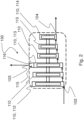
- each centrifugal stage 110 has a compression chamber and an impeller arranged inside it, as shown in Fig. 2 .
- the plurality of centrifugal stages 110 includes an initial stage 112 arranged at the inlet 102 to receive molten urea through it and a final stage 114 arranged at the delivery outlet 104 to send molten urea to the reactor 20 through it.
- the plurality of centrifugal stages 110 comprises an intermediate pressure stage 113, operatively serially arranged between the initial stage 112 and the final stage 114.
- the intermediate-pressure stage 113 has an intermediate outlet 103 configured and arranged to allow the output of molten urea from such stage at an intermediate pressure greater than the suction pressure and lower than the delivery pressure.
- the intermediate pressure is comprised between 3 bar and 15 bar, even more preferably between 5 bar and 10 bar.
- the intermediate pressure is greater than the suction pressure by a value comprised between 2 bar and 14 bar, more preferably between 4 bar and 9 bar.
- the value of said intermediate pressure depends on the serially arrangement of the intermediate-pressure stage 113 in the plurality of centrifugal stages 110.
- the intermediate-pressure stage 113 is a centrifugal stage interposed between the initial stage 112 and the final stage 114.
- the stage at intermediate pressure stage 113 can coincide with the initial stage 112.
- the intermediate outlet 103 is sized and configured to output a flow rate of molten urea comprised between 50% and 75% of the molten urea at the inlet, even more preferably between 60% and 70%, particularly about 67%.
- the intermediate outlet 103 when operated, is preferably located at an upper end of the intermediate-pressure stage 113 to allow a gas extraction or venting.
- the molten urea continuously generates reaction gases, particularly ammonia and carbon dioxide, and the intermediate-pressure stage 113 thus configured allows to convey the gases generated from urea during the movement through the intermediate outlet 103 with operating advantage of the subsequent compression stages.
- the intermediate-pressure stage 113 has a storage volume 115 arranged, an operative configuration, above the impeller, in fluid communication with the compression chamber.
- the centrifugal pump 100 has a casing provided with a dome-shaped portion 116 vertically above the impeller of the intermediate-pressure stage 113 to define the above-mentioned storage volume 115.
- the intermediate outlet 103 is arranged at an upper end of the dome-shaped portion 116.
- the storage volume 115 is configured to receive molten urea and gas from the compression chamber of the intermediate-pressure stage 113 during operation of the centrifugal pump 100 to allow its input through the intermediate outlet 103.
- the intermediate outlet 103 is, when operated, fluidly connected to the separator 10 through a recirculation duct 33, such that to cause a recirculation stream of molten urea from the centrifugal pump 100 to the separator 10 such as to prevent accumulation of solid residues inside it.
- the recirculation duct 33 is fluidly connected to the recirculation inlet 13 of the separator 10.
- the feed duct 32 is connected to the outlet for molten urea 12. This configuration allows to determine a continuous flow of molten urea from the recirculation inlet 13 to the outlet for molten urea 12 through the entire extension of the separator 10.
- the plant 1 further comprises the reactor 20 for producing melamine fluidly connected to the delivery outlet 104 of the centrifugal pump 100 to receive from it pressurized molten urea through the delivery duct 34.
- the centrifugal pump 100 has a variable speed to regulate the flow rate of the molten urea directed to the reactor 20.
- the centrifugal pump 100 has a fixed rotation speed and the plant 1 comprises a regulation valve arranged along the delivery duct 34, between the delivery outlet 104 of the centrifugal pump 100 and the reactor 20, to regulate the flow rate of the molten urea directed to the reactor 20.
- plant 1 comprises two of the above-described centrifugal pumps 100, arranged in parallel for redundancy, as illustrated in Fig. 3 , to compress the molten urea directed from the separator 10 to the reactor 20.
- One of the two centrifugal pumps 100 is configurable in stand-by while the other is running.
- a plurality of valves 40 is arranged along the suction and delivery ducts of the two valves to allow the centrifugal pump 100, when operated, to be connected in line between the separator 10 and the reactor 20 and to isolate the other.
- plant 1 further comprises a first flushing line 41 controlled by a related valve 42 and arranged to cause a fluid coupling between the delivery outlets 104 of the two centrifugal pumps 100, bypassing the valves 40.
- plant 1 can comprise a second flushing line 43 controlled by a related valve 44 and arranged to cause a fluid coupling between the inlets 102 of the two centrifugal pumps 100, bypassing the valves 40.
- Fig. 4 shows an example of an operational configuration of the plant 1 wherein the centrifugal pump 100A is running, the centrifugal pump 100B is in stand-by, the valves 40A, 42 and 44 are open and the valves 40B are closed.
- the re-circulation of the fluid in the centrifugal pump 100B in stand-by can be obtained by leaving open or partially open the valve 40B upstream (or in suction) of the centrifugal pump 100B in stand-by.
- the first and the second flushing line 41 and 43 allows to establish, during the operation of one of the two centrifugal pumps 100, a flow of molten urea from the delivery outlet 104 of the running centrifugal pump 100 to the inlet 102 of the other centrifugal pump 100 in stand-by, circulating inside the pump in stand-by, and reaching the suction line 102 of the running pump.
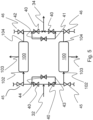
- plant 1 further comprises a system for washing the one or more centrifugal pumps 100 after their shutdown, an example of which is given in Fig. 5 .
- plant 1 comprises a plurality of access portions 45 and 46, fluidly coupled to the centrifugal pumps 100 to allow their emptying and flushing.
- plant 1 comprises a prima access portion 45 upstream of the centrifugal pump 100 and a second access portion 46 downstream of each centrifugal pump 100.
- the first and second access portions 45 e 46 consist of rapid connections equipped with valves, which allow the connection of drainage and / or flushing ducts to perform these operations.
- first and second access portions 45 and 46 allow access to any areas where the molten urea may have solidified, which tends to solidify in the dead points, i.e. without circulation and renewal of the product, for example the areas upstream of the rapid connection valves.
- centrifugal pump with these characteristics in place of the traditional reciprocating pumps allows to process a greater amount of molten urea without having to adopt a large number of reciprocating heads or pumps in parallel.
- centrifugal pump with these characteristics prevents the phenomena of cavitation in the suction and allows not to use additional pumps to pre-compress the molten urea.
- the described centrifugal pump allows to send a recirculation flow rate at right pressure to the vacuum separator, if present, in order to prevent the accumulation of solid residues without requiring a dedicated pump.
- the described centrifugal pump also allows to avoid problems caused to the plant by the delivery pulsating pressure of the reciprocating pumps.
Landscapes
- Engineering & Computer Science (AREA)
- Mechanical Engineering (AREA)
- General Engineering & Computer Science (AREA)
- Chemical & Material Sciences (AREA)
- Organic Chemistry (AREA)
- Physics & Mathematics (AREA)
- Thermal Sciences (AREA)
- Structures Of Non-Positive Displacement Pumps (AREA)
- Organic Low-Molecular-Weight Compounds And Preparation Thereof (AREA)
Description
- The present invention relates to the field of industrial processing of urea, particularly for the production of melamine. In more detail, the present invention relates to a centrifugal pump for processing molten urea and a relative plant, in particular for producing melamine with a high-pressure process.
- The production of melamine by urea pyrolysis according to the global reaction (1) is known:

- The processes for converting urea into melamine are distinguished into two groups: processes performing high-pressure urea pyrolysis and processes performing low-pressure urea pyrolysis.
- Both the processes are typically performed in reactors fed with a molten urea stream. Preferably, the reactor is also fed with an ammonia stream.
- In high-pressure processes, the reaction chamber is always held at a pressure greater than 60 bar and it is provided with heating means maintaining the reagent system at a temperature of about 360°C - 450°C.
- The present invention relates particularly to processes for the high-pressure preparation of melamine. More specifically, in order to produce melamine, it is necessary to handle and pressurize liquid-state urea with a concentration greater than 99.8%, i.e. molten, taking it either from a vacuum separator, in case the urea is fed to the plant as aqueous solution and needs to be concentrated inside the plant itself, or from a surge drum maintained under a slight pressure, in case the urea is fed to the melamine plant already as concentrated, to a reactor operating at a pressure of about 80 bars.
- At present, in order to pressurize the molten urea from the separator to the reactor reciprocating pumps are used. The constant increase of the production capability of plants for producing melamine requested by the market, has determined a proportional increase of urea flow rates to be processed in the plants, resulting in an increase of the volume and number of reciprocating pump heads used, and frequently, in the use of more pumps in parallel, with the result of an increase in the complexity, costs and malfunction risks of the reciprocating pumps currently used with an impact on the operation of the plant itself. The use of reciprocating pumps causes a number of disadvantages.
- Reciprocating pumps are by their nature in each head equipped with valves at the inlet (suction) and at the outlet (delivery) that control their operation. The presence of such valves along the pump's suction flow, and in particular at the inlet on each head, is a bottleneck that results in an speed increase and load loss with a subsequent decrease inside the valve itself causing the release of any gases dissolved in the liquid phase with a risk of cavitation phenomena at the pump inlet.
- The molten urea is subjected to a continuous, though minimal, decomposition with the formation of ammonia and carbon dioxide, that remain dissolved in the liquid phase under constant pressure conditions, but which are released as a gas phase as the pressure decreases, generating cavitation phenomena that impair the proper operation of the reciprocating pumps reducing their performance and often resulting in mechanical faults. For this reason, reciprocating pumps require the use of an additional pump arranged upstream to cause a pre-compression of the molten urea and preventing cavitation at the reciprocating pump inlet.
- Furthermore, the reciprocating pumps have by their nature a pulsating delivery pressure, which requires the use of accumulators downstream the reciprocating pump and other devices capable of damping pulsations and/or operating under pulsating pressures. Moreover, in the production of melamine, this factor affects the reactor subjected to a pulsating feeding which generates the formation of a pulsating reaction gas (see the reaction) with a subsequent internal pulsating pressure and on gases it emits in the pressure control, that also result having a pulsating flow rate, and on the components designated to processing such gases.
- Urea has a melting temperature equal to 133 °C. In order to avoid urea solidification, the pump needs to be drained and washed after its shutdown. The reciprocating pumps with multiple heads arranged in parallel require that each head to be drained and washed individually, and therefore they require complex draining and washing systems. Such systems are detrimental to the reliability of the pump, increasing the possibility of leaks and clogging, and making these operations particularly time-consuming for the operators who could omit complete execution of the same.
- Moreover, the starting of the reciprocating pumps causes a sudden pressure increase in the delivery of the pump itself, which risks to cause malfunctions or damages to the downstream components, particularly to the shut off/check valve, which keeps the reactor under pressure during the urea pre-feeding step wherein the pressure of the reactor is maintained by a constant supply of ammonia. In order to overcome this problem generally the delivery is pre-pressurized in advance, with a consequent increase in the complexity of the plant and of its starting procedures.
- In addition, some plants require the presence of spare pumps arranged in parallel to the main pump and kept in stand-by, ready to be started if the running pump will stop. In order to maintain the spare pump in stand-by it is necessary to keep it empty and continuously flushed with steam to ensure that internally, in case of leakage of the shutoff valves, urea cannot accumulate, and with its subsequent degradation resulting in a blockage. As an alternative, it is necessary to pre-fill the stand-by pump with molten urea, guaranteeing a circulation inside it to avoid solidifications. In reciprocating pumps, establishing a recirculation inside the pump is complicated and difficult to obtain in a uniformly distributed manner due to the multiple heads which are not individually flushed, unless a complex circulation system is created for each individual head, thus resulting in increased operational operations and a high number of possible leakage points of urea outwards.
- The document
CN 109 404 292 A discloses a centrifugal pump according to the preamble ofclaim 1. - A general object of the present invention is to improve the prior art with reference to one or more points of view.
- Particularly, an object of the present invention is to overcome the above disadvantages by using a centrifugal pump for processing molten urea and a relative plant, in particular for producing melamine with a high-pressure process.
- More in detail, object of the present invention is to provide a centrifugal pump for processing molten urea and a relative plant capable of processing a higher amount of molten urea than the prior art, particularly a centrifugal pump having the prevalence conditions necessary to feed molten urea to the production reactor.
- A further object of the present invention is to provide a centrifugal pump for processing molten urea and a relative plant which is less complex than what is currently available.
- A further object of the present invention is to provide a centrifugal pump for processing molten urea and a relative plant having less malfunction risks and lower wear of components.
- Such objectives are achieved by the subject-matter of the independent claims.
- According to a first aspect, the present invention relates to a centrifugal pump for processing molten urea according to
claim 1. - According to a second aspect, the present invention relates to a plant for processing molten urea according to claim 9.
- The present invention will be clearer from the following detailed description to be considered together with the accompanying drawings wherein:
-
Fig. 1 shows a schematic view of a plant for processing molten urea according to the present invention; -
Fig. 2 shows a schematic view of a centrifugal pump for processing molten urea according to the present invention; -
Fig. 3 shows a schematic view of a detail of a plant for processing molten urea according to a possible embodiment of the present invention. -
Fig. 4 shows a schematic view of a detail of a plant for processing molten urea with the possibility of internal circulation. -
Fig.5 shows a schematic view of a detail of a plant for processing molten urea with flushing possibility. - As easily understandable, there are several modes to implement in practice the present invention which is defined in the accompanying claims and is not limited either by the following detailed description or by the accompanying drawings.
- With reference to the attached figures, a plant for processing molten urea, object of the present invention, is generically indicated with the
reference number 1 and hereinafter reference to it will be made with the annotation "plant 1". -
Plant 1 comprises avacuum separator 10 for molten urea provided with aprimary inlet 11, an outlet formolten urea 12, arecirculation inlet 13 and an outlet forgas 14. Preferably, therecirculation inlet 13 is arranged at or in the proximity of an upper end of theseparator 10 and the outlet formolten urea 12 is arranged at or in the proximity of a lower end of theseparator 10. - The
plant 1 also comprises a centrifugal pump for processing molten urea, which forms a further object of the present invention and hereinafter it will be indicated with thereference number 100 and named as "centrifugal pump 100". - The
centrifugal pump 100 has aninlet 102 and adelivery outlet 104. Theinlet 102 corresponds to the suction of thecentrifugal pump 100 and, when operated, is fluidly connected to the outlet formolten urea 12 of theseparator 10 to receive molten urea from it through asuction duct 32. Thedelivery outlet 104 corresponds to the delivery of thecentrifugal pump 100 and, when operated, is fluidly connectable to areactor 20 for the production of melamine from urea, in order to feed it with a flow rate of molten urea through adelivery duct 34. - The
centrifugal pump 100 is configured to receive molten urea at a preselected suction pressure at theinlet 102 and allow an output of molten urea at a delivery pressure at thedelivery outlet 104, greater than the suction pressure. Preferably, the suction pressure is comprised between 0.5 bar and 5 bar, even more preferably between 1 bar and 2 bar, particularly of about 1.5 bar. Such suction pressure is determined by the greater height above ground level of the separator 10 (which operates under conditions of absolute vacuum or slight overpressure) with respect to theinlet 102. The difference in height between theseparator 10 and thepump inlet 102 must therefore be such as to guarantee a positive pressure in any case. - The delivery pressure is preferably comprised between 60 bar and 100 bar, even more preferably between 70 bar and 90 bar, particularly of about 81 bar. Accordingly, the
centrifugal pump 100 has a prevalence preferably comprised between 60 bar and 100 bar, even more preferably between 70 bar and 90 bar, particularly of about 80 bar. - Preferably, the
centrifugal pump 100 is configured to process a flow rate of molten urea greater than 15 m3/h, even more preferably greater than 25 m3/h. - Preferably, the
centrifugal pump 100 comprises a heating system configured to maintain an internal temperature of the molten urea greater than a preselected value, particularly greater than its melting temperature, equal to about 133 °C, in order to avoid solidification inside thecentrifugal pump 100 itself. - Preferably, the
centrifugal pump 100 is multi-stage and comprises a plurality ofcentrifugal stages 110 serially arranged. Generally, eachcentrifugal stage 110 has a compression chamber and an impeller arranged inside it, as shown inFig. 2 . Particularly, the plurality ofcentrifugal stages 110 includes an initial stage 112 arranged at theinlet 102 to receive molten urea through it and a final stage 114 arranged at thedelivery outlet 104 to send molten urea to thereactor 20 through it. - Between the initial stage 112 and the final stage 114 the pressure of the molten urea gradually increases passing through the various
centrifugal stages 110. - The plurality of
centrifugal stages 110 comprises an intermediate pressure stage 113, operatively serially arranged between the initial stage 112 and the final stage 114. - Particularly, the intermediate-pressure stage 113 has an
intermediate outlet 103 configured and arranged to allow the output of molten urea from such stage at an intermediate pressure greater than the suction pressure and lower than the delivery pressure. Preferably, the intermediate pressure is comprised between 3 bar and 15 bar, even more preferably between 5 bar and 10 bar. In other words, the intermediate pressure is greater than the suction pressure by a value comprised between 2 bar and 14 bar, more preferably between 4 bar and 9 bar. - The value of said intermediate pressure depends on the serially arrangement of the intermediate-pressure stage 113 in the plurality of
centrifugal stages 110. Preferably, the intermediate-pressure stage 113 is a centrifugal stage interposed between the initial stage 112 and the final stage 114. In some embodiments, the stage at intermediate pressure stage 113 can coincide with the initial stage 112. - Preferably, the
intermediate outlet 103 is sized and configured to output a flow rate of molten urea comprised between 50% and 75% of the molten urea at the inlet, even more preferably between 60% and 70%, particularly about 67%. - Moreover, the
intermediate outlet 103 when operated, is preferably located at an upper end of the intermediate-pressure stage 113 to allow a gas extraction or venting. The molten urea continuously generates reaction gases, particularly ammonia and carbon dioxide, and the intermediate-pressure stage 113 thus configured allows to convey the gases generated from urea during the movement through theintermediate outlet 103 with operating advantage of the subsequent compression stages. - Preferably, the intermediate-pressure stage 113 has a
storage volume 115 arranged, an operative configuration, above the impeller, in fluid communication with the compression chamber. Particularly, thecentrifugal pump 100 has a casing provided with a dome-shapedportion 116 vertically above the impeller of the intermediate-pressure stage 113 to define the above-mentionedstorage volume 115. Theintermediate outlet 103 is arranged at an upper end of the dome-shapedportion 116. - The
storage volume 115 is configured to receive molten urea and gas from the compression chamber of the intermediate-pressure stage 113 during operation of thecentrifugal pump 100 to allow its input through theintermediate outlet 103. - The
intermediate outlet 103 is, when operated, fluidly connected to theseparator 10 through arecirculation duct 33, such that to cause a recirculation stream of molten urea from thecentrifugal pump 100 to theseparator 10 such as to prevent accumulation of solid residues inside it. Particularly, therecirculation duct 33 is fluidly connected to therecirculation inlet 13 of theseparator 10. Thefeed duct 32 is connected to the outlet for moltenurea 12. This configuration allows to determine a continuous flow of molten urea from therecirculation inlet 13 to the outlet for moltenurea 12 through the entire extension of theseparator 10. - The
plant 1 further comprises thereactor 20 for producing melamine fluidly connected to thedelivery outlet 104 of thecentrifugal pump 100 to receive from it pressurized molten urea through thedelivery duct 34. - According to a possible embodiment, the
centrifugal pump 100 has a variable speed to regulate the flow rate of the molten urea directed to thereactor 20. - According to a possible alternative embodiment, the
centrifugal pump 100 has a fixed rotation speed and theplant 1 comprises a regulation valve arranged along thedelivery duct 34, between thedelivery outlet 104 of thecentrifugal pump 100 and thereactor 20, to regulate the flow rate of the molten urea directed to thereactor 20. - Preferably,
plant 1 comprises two of the above-describedcentrifugal pumps 100, arranged in parallel for redundancy, as illustrated inFig. 3 , to compress the molten urea directed from theseparator 10 to thereactor 20. One of the twocentrifugal pumps 100 is configurable in stand-by while the other is running. - A plurality of
valves 40 is arranged along the suction and delivery ducts of the two valves to allow thecentrifugal pump 100, when operated, to be connected in line between theseparator 10 and thereactor 20 and to isolate the other. Preferably,plant 1 further comprises afirst flushing line 41 controlled by arelated valve 42 and arranged to cause a fluid coupling between thedelivery outlets 104 of the twocentrifugal pumps 100, bypassing thevalves 40. Moreover,plant 1 can comprise asecond flushing line 43 controlled by arelated valve 44 and arranged to cause a fluid coupling between theinlets 102 of the twocentrifugal pumps 100, bypassing thevalves 40. -
Fig. 4 shows an example of an operational configuration of theplant 1 wherein thecentrifugal pump 100A is running, thecentrifugal pump 100B is in stand-by, thevalves valves 40B are closed. - In the absence of the
second flushing line 43, the re-circulation of the fluid in thecentrifugal pump 100B in stand-by can be obtained by leaving open or partially open thevalve 40B upstream (or in suction) of thecentrifugal pump 100B in stand-by. Advantageously, the first and thesecond flushing line centrifugal pumps 100, a flow of molten urea from thedelivery outlet 104 of the runningcentrifugal pump 100 to theinlet 102 of the othercentrifugal pump 100 in stand-by, circulating inside the pump in stand-by, and reaching thesuction line 102 of the running pump. - By means of this internal circulation in the stand-by pump it is avoided that molten urea can stay inside it with the possibility of decomposition and solidification.
- Preferably,
plant 1 further comprises a system for washing the one or morecentrifugal pumps 100 after their shutdown, an example of which is given inFig. 5 . - The washing of the
centrifugal pumps 100 consists in emptying them from the molten urea by draining them into a recovery manifold, followed by flushing with steam and subsequently with water which are in turn recovered to avoid environmental pollution. For this purpose,plant 1 comprises a plurality ofaccess portions centrifugal pumps 100 to allow their emptying and flushing. Particularlyplant 1 comprises aprima access portion 45 upstream of thecentrifugal pump 100 and asecond access portion 46 downstream of eachcentrifugal pump 100. Preferably, the first and second access portions 45e 46 consist of rapid connections equipped with valves, which allow the connection of drainage and / or flushing ducts to perform these operations. - These first and
second access portions - The described embodiments overcome the limitations of the prior art.
- The use of the centrifugal pump with these characteristics in place of the traditional reciprocating pumps allows to process a greater amount of molten urea without having to adopt a large number of reciprocating heads or pumps in parallel.
- The use of the centrifugal pump with these characteristics prevents the phenomena of cavitation in the suction and allows not to use additional pumps to pre-compress the molten urea.
- The described centrifugal pump allows to send a recirculation flow rate at right pressure to the vacuum separator, if present, in order to prevent the accumulation of solid residues without requiring a dedicated pump.
- The described centrifugal pump also allows to avoid problems caused to the plant by the delivery pulsating pressure of the reciprocating pumps.
- The use of the described solutions makes it possible to create simpler plants having less malfunction risks and lower wear of components.
- Comparing the construction and operating peculiarities of centrifugal pumps with respect to reciprocating pumps, the greater simplicity of washing the former compared to the latter is clear, considering that:
- there is only one pumping body and not a plurality of in parallel bodies with the possibility of by-passing by the washing fluid or urea retention during the drainage phase, which make the operation unsafe;
- they can be flushed in both directions, lacking in the internal check valves present in the reciprocating pumps.
Claims (15)
- A centrifugal pump (100) for processing molten urea having:- an inlet (102) adapted to receive molten urea at a suction pressure;- a delivery outlet (104) adapted to allow an output of molten urea at a delivery pressure greater than said suction pressure;wherein said centrifugal pump (100) comprises a heating system adapted to maintain a temperature of the molten urea inside the centrifugal pump (100) greater than a predetermined value,the centrifugal pump being characterised in thatit has an intermediate outlet (103) adapted to allow an output of molten urea at an intermediate pressure greater than said suction pressure and lower than said delivery pressure.
- The centrifugal pump (100) according to claim 1, comprising a plurality of centrifugal stages (110) arranged in series;said plurality of centrifugal stages (110) comprising:- an intermediate pressure stage (113) arranged and/or configured to cause a molten urea pressure equal to said intermediate pressure;said intermediate outlet (103) being arranged at said intermediate pressure stage (113) to receive molten urea from said intermediate pressure stage (113).
- The centrifugal pump (100) according to claim 2, wherein said plurality of centrifugal stages (110) comprises:- an initial stage (112) arranged at said inlet (102) to receive molten urea from said inlet (102);- a final stage (114) arranged at said delivery outlet (104) to send molten urea to said delivery outlet (104);said intermediate pressure stage (113) being operatively arranged between said initial stage (112) and said final stage (114).
- The centrifugal pump (100) according to claim 2 or 3, wherein said intermediate outlet (103) is arranged at an upper end of said intermediate pressure stage (113) to allow a gas extraction from said intermediate pressure stage (113) through said intermediate outlet (103).
- The centrifugal pump (100) according to claim 4, wherein said intermediate pressure stage (113) has a compression chamber, an impeller arranged in said compression chamber and a storage volume (115) arranged above said impeller, in fluid communication with said compression chamber; said storage volume (115) being configured to receive molten urea and gas from said compression chamber during an operation of the centrifugal pump (100) and said intermediate outlet (103) being arranged at an upper end of said storage volume (115).
- The centrifugal pump (100) according to claim 5, comprising a casing provided with a dome-shaped portion (116), said dome-shaped portion (116) defining superiorly said storage volume (115).
- The centrifugal pump (100) according to one or more of the preceding claims, adapted to process a flow rate of molten urea greater than 15 m3/h, preferably greater than 25m3/h, wherein said delivery pressure is greater than said suction pressure by a value comprised between 50 bar and 100 bar, preferably between 70 bar and 90 bar.
- The centrifugal pump (100) according to one or more of the preceding claims, wherein said intermediate pressure is greater than said suction pressure by a value comprised between 2 bar and 14 bar, preferably between 4 bar and 9 bar, and wherein said centrifugal pump (100) is configured to direct a flow rate of molten urea comprised between 50% and 75% of the molten urea at the inlet, preferably between 60% and 70%, through said intermediate outlet (103).
- A plant (1) for processing molten urea, in particular for producing melamine with a high-pressure process, comprising:- a separator (10) for molten urea having a primary inlet (11), a recirculation inlet (13) and an outlet for molten urea (12);- at least one centrifugal pump (100) having:- an inlet (102) adapted to receive molten urea at a suction pressure;- a delivery outlet (104) adapted to allow an output of molten urea at a delivery pressure greater than said suction pressure;- an intermediate outlet (103) adapted to allow an output of molten urea at an intermediate pressure greater than said suction pressure and lower than said delivery pressure;wherein the inlet (102) of the centrifugal pump (100) is fluidly connected to the outlet for molten urea (12) of the separator (10) to receive molten urea at the inlet coming from said separator (10);wherein the recirculation inlet (13) of the separator (10) is fluidly connected to the intermediate outlet (103) of the centrifugal pump (100) to receive recirculation molten urea at the inlet coming from said centrifugal pump (100).
- The plant according to claim 9, wherein the centrifugal pump (100) is according to one or more of claims 1 to 8.
- The plant (1) according to claim 9 or 10, comprising a reactor (20) for producing melamine in a high-pressure process, fluidly connected to the delivery outlet (104) of said centrifugal pump (100) to receive pressurized molten urea from said centrifugal pump (100).
- The plant (1) according to claim 11, whereinsaid centrifugal pump (100) has a variable speed to regulate a flow rate and/or a pressure of the molten urea directed to said reactor (20); orsaid centrifugal pump (100) has a fixed rotation speed and said plant (1) comprises a regulation valve operatively arranged between the delivery outlet (104) of said centrifugal pump (100) and said reactor (20) to regulate a flow rate and/or a pressure of the molten urea directed to said reactor (20).
- The plant (1) according to one or more of claims 9 to 12, comprising two centrifugal pumps (100) according to the pump features of claim 9,said two centrifugal pumps (100) being arranged in parallel;one of said two centrifugal pumps (100) being configurable in stand-by while the other is running.
- The plant (1) according to claim 13, comprising a first flushing line (41) adapted to cause a fluid coupling between the delivery outlets (104) of said two centrifugal pumps (100) and a second flushing line (43) adapted to cause a fluid coupling between the inlets (102) of said two centrifugal pumps (100);
the running centrifugal pump (100) being adapted to cause a flow of molten urea from the delivery outlet (104) to the inlet (102) of said centrifugal pump (100) in stand-by through said first and second flushing line (41, 43) in an operating condition of said plant (1). - The plant (1) according to one or more of claims 9 to 14, comprising at least one first access portion (45) fluidly coupled to said at least one centrifugal pump (100) upstream of said at least one centrifugal pump (100) and at least one second access portion (46) fluidly coupled to said at least one centrifugal pump (100) downstream of said at least one centrifugal pump (100);
said first and second access portions (45, 46) being adapted to drain and/or flush said at least one centrifugal pump (100).
Applications Claiming Priority (1)
| Application Number | Priority Date | Filing Date | Title |
|---|---|---|---|
| IT102019000023160A IT201900023160A1 (en) | 2019-12-06 | 2019-12-06 | Centrifugal pump for processing molten urea and relative plant |
Publications (4)
| Publication Number | Publication Date |
|---|---|
| EP3831809A1 EP3831809A1 (en) | 2021-06-09 |
| EP3831809B1 true EP3831809B1 (en) | 2023-09-13 |
| EP3831809C0 EP3831809C0 (en) | 2023-09-13 |
| EP3831809B8 EP3831809B8 (en) | 2023-10-18 |
Family
ID=70009264
Family Applications (1)
| Application Number | Title | Priority Date | Filing Date |
|---|---|---|---|
| EP20211599.4A Active EP3831809B8 (en) | 2019-12-06 | 2020-12-03 | Centrifugal pump for processing molten urea and relative plant |
Country Status (6)
| Country | Link |
|---|---|
| US (1) | US20210172459A1 (en) |
| EP (1) | EP3831809B8 (en) |
| CN (1) | CN112922843B (en) |
| BR (1) | BR102020024588A2 (en) |
| IT (1) | IT201900023160A1 (en) |
| PL (1) | PL3831809T3 (en) |
Families Citing this family (2)
| Publication number | Priority date | Publication date | Assignee | Title |
|---|---|---|---|---|
| CN114452897A (en) * | 2022-01-06 | 2022-05-10 | 四川金象赛瑞化工股份有限公司 | Urea feeding device, urea feeding method, melamine production device and melamine production method |
| CN118874001A (en) * | 2024-10-08 | 2024-11-01 | 西安泵阀总厂有限公司 | A separation type gas-liquid two-phase pumping system |
Citations (1)
| Publication number | Priority date | Publication date | Assignee | Title |
|---|---|---|---|---|
| CN109404292A (en) * | 2018-12-09 | 2019-03-01 | 大连深蓝泵业有限公司 | Large chemical fertilizer urea plant high-pressure pump |
Family Cites Families (8)
| Publication number | Priority date | Publication date | Assignee | Title |
|---|---|---|---|---|
| US3118386A (en) * | 1964-01-21 | Multi-stage centrifugal pump | ||
| SU899538A1 (en) * | 1969-01-21 | 1982-01-23 | Предприятие П/Я Г-4302 | Process for producing urea and melamine |
| EP1461139B1 (en) * | 2001-11-16 | 2005-08-31 | AMI Agrolinz Melamine International GmbH | Method for purifying off-gases from a melamine-producing installation |
| CN202250886U (en) * | 2011-09-26 | 2012-05-30 | 大连深蓝泵业有限公司 | Dual-drum self-balancing sectional type multi-stage pump |
| CN202560651U (en) * | 2012-02-22 | 2012-11-28 | 肖大银 | Novel special double-suction molten urea pump |
| EP3187736B1 (en) * | 2015-12-30 | 2021-04-14 | Sulzer Management AG | Multi-stage horizontal centrifugal pump for pumping a fluid and method for repairing the same |
| EP3486493B1 (en) * | 2017-01-10 | 2020-05-13 | Mitsubishi Heavy Industries, Ltd. | Vertical pump and urea synthesizing plant |
| CN109723618A (en) * | 2018-12-28 | 2019-05-07 | 四川金象赛瑞化工股份有限公司 | Online alternative mean, application and the system of urea pump |
-
2019
- 2019-12-06 IT IT102019000023160A patent/IT201900023160A1/en unknown
-
2020
- 2020-12-01 BR BR102020024588-0A patent/BR102020024588A2/en not_active Application Discontinuation
- 2020-12-03 PL PL20211599.4T patent/PL3831809T3/en unknown
- 2020-12-03 EP EP20211599.4A patent/EP3831809B8/en active Active
- 2020-12-04 CN CN202011409981.7A patent/CN112922843B/en active Active
- 2020-12-04 US US17/111,837 patent/US20210172459A1/en not_active Abandoned
Patent Citations (1)
| Publication number | Priority date | Publication date | Assignee | Title |
|---|---|---|---|---|
| CN109404292A (en) * | 2018-12-09 | 2019-03-01 | 大连深蓝泵业有限公司 | Large chemical fertilizer urea plant high-pressure pump |
Also Published As
| Publication number | Publication date |
|---|---|
| PL3831809T3 (en) | 2024-01-29 |
| EP3831809B8 (en) | 2023-10-18 |
| EP3831809C0 (en) | 2023-09-13 |
| EP3831809A1 (en) | 2021-06-09 |
| US20210172459A1 (en) | 2021-06-10 |
| BR102020024588A2 (en) | 2021-09-08 |
| CN112922843B (en) | 2025-07-08 |
| IT201900023160A1 (en) | 2021-06-06 |
| CN112922843A (en) | 2021-06-08 |
Similar Documents
| Publication | Publication Date | Title |
|---|---|---|
| US20140373541A1 (en) | Method and apparatus for safety operation of extraction steam turbine utilized for power generation plant | |
| US20210172459A1 (en) | Centrifugal pump for processing molten urea and relative plant | |
| US10302074B2 (en) | Hydraulic drive for a pressure booster | |
| JP7422186B2 (en) | Boiling water reactor startup/shutdown hydrogen injection system and method | |
| CN116677918B (en) | Well head gas conveying device of coal bed gas drainage and production well and using method | |
| AU3167100A (en) | Method and device for desalting water | |
| CN113431787A (en) | System for preventing recirculation valve of feed pump from leaking under condition of adapting to frequent peak regulation situation | |
| US11572899B2 (en) | Pressure exchanger for hydraulic fracking | |
| EP1592839B1 (en) | Method for washing pulp in a bleaching line and a bleaching line | |
| US9150290B2 (en) | Ballast system | |
| CN114411170B (en) | Hydrogen production system and method | |
| CN216203281U (en) | Condensate water recovery device under pressure | |
| CN213294793U (en) | Two-stage DTRO system capable of being maintained on line | |
| CN211754787U (en) | Prevent blockking up olefin polymerization catalyst pipeline device | |
| CN210509768U (en) | Closed hydraulic system for oil cylinder driving | |
| CN110183557B (en) | Shutdown control method and system for polyethylene device | |
| RU2020139155A (en) | Centrifugal pump for molten urea processing and associated installation | |
| CN210658178U (en) | Parallel water pumping device | |
| CN107368048B (en) | Design method of underground water supply pump station structure control system | |
| CN107537407B (en) | Adiponitrile hydrogenation reaction system and method for treating reactor heavy blockage by using same | |
| CN220614873U (en) | Large-caliber pipe vacuum box | |
| CN211624810U (en) | Pressure regulating valve draining structure | |
| CN105864744A (en) | Novel device for conveying low-pressure fluid to high-pressure fluid | |
| CN206637231U (en) | Novel oil filtering machine | |
| CN223952940U (en) | Boosting and speed increasing hydraulic system |
Legal Events
| Date | Code | Title | Description |
|---|---|---|---|
| PUAI | Public reference made under article 153(3) epc to a published international application that has entered the european phase |
Free format text: ORIGINAL CODE: 0009012 |
|
| STAA | Information on the status of an ep patent application or granted ep patent |
Free format text: STATUS: THE APPLICATION HAS BEEN PUBLISHED |
|
| AK | Designated contracting states |
Kind code of ref document: A1 Designated state(s): AL AT BE BG CH CY CZ DE DK EE ES FI FR GB GR HR HU IE IS IT LI LT LU LV MC MK MT NL NO PL PT RO RS SE SI SK SM TR |
|
| STAA | Information on the status of an ep patent application or granted ep patent |
Free format text: STATUS: REQUEST FOR EXAMINATION WAS MADE |
|
| 17P | Request for examination filed |
Effective date: 20211125 |
|
| RBV | Designated contracting states (corrected) |
Designated state(s): AL AT BE BG CH CY CZ DE DK EE ES FI FR GB GR HR HU IE IS IT LI LT LU LV MC MK MT NL NO PL PT RO RS SE SI SK SM TR |
|
| GRAP | Despatch of communication of intention to grant a patent |
Free format text: ORIGINAL CODE: EPIDOSNIGR1 |
|
| STAA | Information on the status of an ep patent application or granted ep patent |
Free format text: STATUS: GRANT OF PATENT IS INTENDED |
|
| INTG | Intention to grant announced |
Effective date: 20230404 |
|
| RIN1 | Information on inventor provided before grant (corrected) |
Inventor name: DE AMICIS, ALBERTO Inventor name: DI RUOCCO, GIUSEPPE Inventor name: SANTUCCI, ROBERTO |
|
| GRAS | Grant fee paid |
Free format text: ORIGINAL CODE: EPIDOSNIGR3 |
|
| GRAA | (expected) grant |
Free format text: ORIGINAL CODE: 0009210 |
|
| STAA | Information on the status of an ep patent application or granted ep patent |
Free format text: STATUS: THE PATENT HAS BEEN GRANTED |
|
| AK | Designated contracting states |
Kind code of ref document: B1 Designated state(s): AL AT BE BG CH CY CZ DE DK EE ES FI FR GB GR HR HU IE IS IT LI LT LU LV MC MK MT NL NO PL PT RO RS SE SI SK SM TR |
|
| REG | Reference to a national code |
Ref country code: CH Ref legal event code: EP |
|
| RAP2 | Party data changed (patent owner data changed or rights of a patent transferred) |
Owner name: PROMAN AG |
|
| REG | Reference to a national code |
Ref country code: CH Ref legal event code: PK Free format text: BERICHTIGUNG B8 |
|
| REG | Reference to a national code |
Ref country code: DE Ref legal event code: R096 Ref document number: 602020017569 Country of ref document: DE |
|
| REG | Reference to a national code |
Ref country code: IE Ref legal event code: FG4D |
|
| U01 | Request for unitary effect filed |
Effective date: 20231010 |
|
| U07 | Unitary effect registered |
Designated state(s): AT BE BG DE DK EE FI FR IT LT LU LV MT NL PT SE SI Effective date: 20231018 |
|
| PG25 | Lapsed in a contracting state [announced via postgrant information from national office to epo] |
Ref country code: GR Free format text: LAPSE BECAUSE OF FAILURE TO SUBMIT A TRANSLATION OF THE DESCRIPTION OR TO PAY THE FEE WITHIN THE PRESCRIBED TIME-LIMIT Effective date: 20231214 |
|
| PG25 | Lapsed in a contracting state [announced via postgrant information from national office to epo] |
Ref country code: RS Free format text: LAPSE BECAUSE OF FAILURE TO SUBMIT A TRANSLATION OF THE DESCRIPTION OR TO PAY THE FEE WITHIN THE PRESCRIBED TIME-LIMIT Effective date: 20230913 Ref country code: NO Free format text: LAPSE BECAUSE OF FAILURE TO SUBMIT A TRANSLATION OF THE DESCRIPTION OR TO PAY THE FEE WITHIN THE PRESCRIBED TIME-LIMIT Effective date: 20231213 Ref country code: HR Free format text: LAPSE BECAUSE OF FAILURE TO SUBMIT A TRANSLATION OF THE DESCRIPTION OR TO PAY THE FEE WITHIN THE PRESCRIBED TIME-LIMIT Effective date: 20230913 Ref country code: GR Free format text: LAPSE BECAUSE OF FAILURE TO SUBMIT A TRANSLATION OF THE DESCRIPTION OR TO PAY THE FEE WITHIN THE PRESCRIBED TIME-LIMIT Effective date: 20231214 |
|
| U20 | Renewal fee for the european patent with unitary effect paid |
Year of fee payment: 4 Effective date: 20231227 |
|
| PG25 | Lapsed in a contracting state [announced via postgrant information from national office to epo] |
Ref country code: IS Free format text: LAPSE BECAUSE OF FAILURE TO SUBMIT A TRANSLATION OF THE DESCRIPTION OR TO PAY THE FEE WITHIN THE PRESCRIBED TIME-LIMIT Effective date: 20240113 |
|
| PG25 | Lapsed in a contracting state [announced via postgrant information from national office to epo] |
Ref country code: ES Free format text: LAPSE BECAUSE OF FAILURE TO SUBMIT A TRANSLATION OF THE DESCRIPTION OR TO PAY THE FEE WITHIN THE PRESCRIBED TIME-LIMIT Effective date: 20230913 |
|
| PG25 | Lapsed in a contracting state [announced via postgrant information from national office to epo] |
Ref country code: SM Free format text: LAPSE BECAUSE OF FAILURE TO SUBMIT A TRANSLATION OF THE DESCRIPTION OR TO PAY THE FEE WITHIN THE PRESCRIBED TIME-LIMIT Effective date: 20230913 Ref country code: RO Free format text: LAPSE BECAUSE OF FAILURE TO SUBMIT A TRANSLATION OF THE DESCRIPTION OR TO PAY THE FEE WITHIN THE PRESCRIBED TIME-LIMIT Effective date: 20230913 Ref country code: IS Free format text: LAPSE BECAUSE OF FAILURE TO SUBMIT A TRANSLATION OF THE DESCRIPTION OR TO PAY THE FEE WITHIN THE PRESCRIBED TIME-LIMIT Effective date: 20240113 Ref country code: ES Free format text: LAPSE BECAUSE OF FAILURE TO SUBMIT A TRANSLATION OF THE DESCRIPTION OR TO PAY THE FEE WITHIN THE PRESCRIBED TIME-LIMIT Effective date: 20230913 Ref country code: CZ Free format text: LAPSE BECAUSE OF FAILURE TO SUBMIT A TRANSLATION OF THE DESCRIPTION OR TO PAY THE FEE WITHIN THE PRESCRIBED TIME-LIMIT Effective date: 20230913 Ref country code: SK Free format text: LAPSE BECAUSE OF FAILURE TO SUBMIT A TRANSLATION OF THE DESCRIPTION OR TO PAY THE FEE WITHIN THE PRESCRIBED TIME-LIMIT Effective date: 20230913 |
|
| REG | Reference to a national code |
Ref country code: DE Ref legal event code: R097 Ref document number: 602020017569 Country of ref document: DE |
|
| PLBE | No opposition filed within time limit |
Free format text: ORIGINAL CODE: 0009261 |
|
| STAA | Information on the status of an ep patent application or granted ep patent |
Free format text: STATUS: NO OPPOSITION FILED WITHIN TIME LIMIT |
|
| 26N | No opposition filed |
Effective date: 20240614 |
|
| PG25 | Lapsed in a contracting state [announced via postgrant information from national office to epo] |
Ref country code: MC Free format text: LAPSE BECAUSE OF FAILURE TO SUBMIT A TRANSLATION OF THE DESCRIPTION OR TO PAY THE FEE WITHIN THE PRESCRIBED TIME-LIMIT Effective date: 20230913 |
|
| PG25 | Lapsed in a contracting state [announced via postgrant information from national office to epo] |
Ref country code: MC Free format text: LAPSE BECAUSE OF FAILURE TO SUBMIT A TRANSLATION OF THE DESCRIPTION OR TO PAY THE FEE WITHIN THE PRESCRIBED TIME-LIMIT Effective date: 20230913 |
|
| REG | Reference to a national code |
Ref country code: IE Ref legal event code: MM4A |
|
| PG25 | Lapsed in a contracting state [announced via postgrant information from national office to epo] |
Ref country code: IE Free format text: LAPSE BECAUSE OF NON-PAYMENT OF DUE FEES Effective date: 20231203 |
|
| PG25 | Lapsed in a contracting state [announced via postgrant information from national office to epo] |
Ref country code: IE Free format text: LAPSE BECAUSE OF NON-PAYMENT OF DUE FEES Effective date: 20231203 |
|
| U20 | Renewal fee for the european patent with unitary effect paid |
Year of fee payment: 5 Effective date: 20241227 |
|
| U1N | Appointed representative for the unitary patent procedure changed after the registration of the unitary effect |
Representative=s name: BIRD & BIRD SOCIETA TRA AVVOCATI S.R.L.; IT |
|
| PG25 | Lapsed in a contracting state [announced via postgrant information from national office to epo] |
Ref country code: CY Free format text: LAPSE BECAUSE OF FAILURE TO SUBMIT A TRANSLATION OF THE DESCRIPTION OR TO PAY THE FEE WITHIN THE PRESCRIBED TIME-LIMIT; INVALID AB INITIO Effective date: 20201203 |
|
| PG25 | Lapsed in a contracting state [announced via postgrant information from national office to epo] |
Ref country code: HU Free format text: LAPSE BECAUSE OF FAILURE TO SUBMIT A TRANSLATION OF THE DESCRIPTION OR TO PAY THE FEE WITHIN THE PRESCRIBED TIME-LIMIT; INVALID AB INITIO Effective date: 20201203 |
|
| GBPC | Gb: european patent ceased through non-payment of renewal fee |
Effective date: 20241203 |
|
| PG25 | Lapsed in a contracting state [announced via postgrant information from national office to epo] |
Ref country code: GB Free format text: LAPSE BECAUSE OF NON-PAYMENT OF DUE FEES Effective date: 20241203 |
|
| REG | Reference to a national code |
Ref country code: CH Ref legal event code: U11 Free format text: ST27 STATUS EVENT CODE: U-0-0-U10-U11 (AS PROVIDED BY THE NATIONAL OFFICE) Effective date: 20260101 |
|
| PGFP | Annual fee paid to national office [announced via postgrant information from national office to epo] |
Ref country code: TR Payment date: 20251121 Year of fee payment: 6 |
|
| PGFP | Annual fee paid to national office [announced via postgrant information from national office to epo] |
Ref country code: PL Payment date: 20251119 Year of fee payment: 6 |
|
| U20 | Renewal fee for the european patent with unitary effect paid |
Year of fee payment: 6 Effective date: 20251229 |
|
| REG | Reference to a national code |
Ref country code: CH Ref legal event code: R14 Free format text: ST27 STATUS EVENT CODE: U-0-0-R10-R14 (AS PROVIDED BY THE NATIONAL OFFICE) Effective date: 20260311 Ref country code: CH Ref legal event code: R17 Free format text: ST27 STATUS EVENT CODE: U-0-0-R10-R17 (AS PROVIDED BY THE NATIONAL OFFICE) Effective date: 20260311 |
|
| REG | Reference to a national code |
Ref country code: CH Ref legal event code: S20 Free format text: ST27 STATUS EVENT CODE: U-0-0-S10-S20 (AS PROVIDED BY THE NATIONAL OFFICE) Effective date: 20260317 |
|
| U1K | Transfer of rights of the unitary patent after the registration of the unitary effect |
Owner name: EUROTECNICA CONTRACTORS AND ENGINEERS S.P.A.; IT |
|
| PGFP | Annual fee paid to national office [announced via postgrant information from national office to epo] |
Ref country code: CH Payment date: 20260101 Year of fee payment: 6 |