EP3831774A1 - Method for preparing carbon nanotubes - Google Patents
Method for preparing carbon nanotubes Download PDFInfo
- Publication number
- EP3831774A1 EP3831774A1 EP19840337.0A EP19840337A EP3831774A1 EP 3831774 A1 EP3831774 A1 EP 3831774A1 EP 19840337 A EP19840337 A EP 19840337A EP 3831774 A1 EP3831774 A1 EP 3831774A1
- Authority
- EP
- European Patent Office
- Prior art keywords
- carbon nanotubes
- preparing
- drying
- vacuum drying
- carried out
- Prior art date
- Legal status (The legal status is an assumption and is not a legal conclusion. Google has not performed a legal analysis and makes no representation as to the accuracy of the status listed.)
- Granted
Links
Images
Classifications
-
- B—PERFORMING OPERATIONS; TRANSPORTING
- B01—PHYSICAL OR CHEMICAL PROCESSES OR APPARATUS IN GENERAL
- B01J—CHEMICAL OR PHYSICAL PROCESSES, e.g. CATALYSIS OR COLLOID CHEMISTRY; THEIR RELEVANT APPARATUS
- B01J35/00—Catalysts, in general, characterised by their form or physical properties
- B01J35/60—Catalysts, in general, characterised by their form or physical properties characterised by their surface properties or porosity
- B01J35/61—Surface area
- B01J35/615—100-500 m2/g
-
- C—CHEMISTRY; METALLURGY
- C01—INORGANIC CHEMISTRY
- C01B—NON-METALLIC ELEMENTS; COMPOUNDS THEREOF; METALLOIDS OR COMPOUNDS THEREOF NOT COVERED BY SUBCLASS C01C
- C01B32/00—Carbon; Compounds thereof
- C01B32/15—Nano-sized carbon materials
- C01B32/158—Carbon nanotubes
- C01B32/16—Preparation
- C01B32/162—Preparation characterised by catalysts
-
- B—PERFORMING OPERATIONS; TRANSPORTING
- B01—PHYSICAL OR CHEMICAL PROCESSES OR APPARATUS IN GENERAL
- B01J—CHEMICAL OR PHYSICAL PROCESSES, e.g. CATALYSIS OR COLLOID CHEMISTRY; THEIR RELEVANT APPARATUS
- B01J21/00—Catalysts comprising the elements, oxides, or hydroxides of magnesium, boron, aluminium, carbon, silicon, titanium, zirconium, or hafnium
- B01J21/02—Boron or aluminium; Oxides or hydroxides thereof
-
- B—PERFORMING OPERATIONS; TRANSPORTING
- B01—PHYSICAL OR CHEMICAL PROCESSES OR APPARATUS IN GENERAL
- B01J—CHEMICAL OR PHYSICAL PROCESSES, e.g. CATALYSIS OR COLLOID CHEMISTRY; THEIR RELEVANT APPARATUS
- B01J21/00—Catalysts comprising the elements, oxides, or hydroxides of magnesium, boron, aluminium, carbon, silicon, titanium, zirconium, or hafnium
- B01J21/02—Boron or aluminium; Oxides or hydroxides thereof
- B01J21/04—Alumina
-
- B—PERFORMING OPERATIONS; TRANSPORTING
- B01—PHYSICAL OR CHEMICAL PROCESSES OR APPARATUS IN GENERAL
- B01J—CHEMICAL OR PHYSICAL PROCESSES, e.g. CATALYSIS OR COLLOID CHEMISTRY; THEIR RELEVANT APPARATUS
- B01J23/00—Catalysts comprising metals or metal oxides or hydroxides, not provided for in group B01J21/00
- B01J23/16—Catalysts comprising metals or metal oxides or hydroxides, not provided for in group B01J21/00 of arsenic, antimony, bismuth, vanadium, niobium, tantalum, polonium, chromium, molybdenum, tungsten, manganese, technetium or rhenium
- B01J23/20—Vanadium, niobium or tantalum
- B01J23/22—Vanadium
-
- B—PERFORMING OPERATIONS; TRANSPORTING
- B01—PHYSICAL OR CHEMICAL PROCESSES OR APPARATUS IN GENERAL
- B01J—CHEMICAL OR PHYSICAL PROCESSES, e.g. CATALYSIS OR COLLOID CHEMISTRY; THEIR RELEVANT APPARATUS
- B01J23/00—Catalysts comprising metals or metal oxides or hydroxides, not provided for in group B01J21/00
- B01J23/70—Catalysts comprising metals or metal oxides or hydroxides, not provided for in group B01J21/00 of the iron group metals or copper
- B01J23/74—Iron group metals
-
- B—PERFORMING OPERATIONS; TRANSPORTING
- B01—PHYSICAL OR CHEMICAL PROCESSES OR APPARATUS IN GENERAL
- B01J—CHEMICAL OR PHYSICAL PROCESSES, e.g. CATALYSIS OR COLLOID CHEMISTRY; THEIR RELEVANT APPARATUS
- B01J23/00—Catalysts comprising metals or metal oxides or hydroxides, not provided for in group B01J21/00
- B01J23/70—Catalysts comprising metals or metal oxides or hydroxides, not provided for in group B01J21/00 of the iron group metals or copper
- B01J23/76—Catalysts comprising metals or metal oxides or hydroxides, not provided for in group B01J21/00 of the iron group metals or copper combined with metals, oxides or hydroxides provided for in groups B01J23/02 - B01J23/36
- B01J23/84—Catalysts comprising metals or metal oxides or hydroxides, not provided for in group B01J21/00 of the iron group metals or copper combined with metals, oxides or hydroxides provided for in groups B01J23/02 - B01J23/36 with arsenic, antimony, bismuth, vanadium, niobium, tantalum, polonium, chromium, molybdenum, tungsten, manganese, technetium or rhenium
- B01J23/847—Vanadium, niobium or tantalum or polonium
- B01J23/8472—Vanadium
-
- B—PERFORMING OPERATIONS; TRANSPORTING
- B01—PHYSICAL OR CHEMICAL PROCESSES OR APPARATUS IN GENERAL
- B01J—CHEMICAL OR PHYSICAL PROCESSES, e.g. CATALYSIS OR COLLOID CHEMISTRY; THEIR RELEVANT APPARATUS
- B01J23/00—Catalysts comprising metals or metal oxides or hydroxides, not provided for in group B01J21/00
- B01J23/70—Catalysts comprising metals or metal oxides or hydroxides, not provided for in group B01J21/00 of the iron group metals or copper
- B01J23/76—Catalysts comprising metals or metal oxides or hydroxides, not provided for in group B01J21/00 of the iron group metals or copper combined with metals, oxides or hydroxides provided for in groups B01J23/02 - B01J23/36
- B01J23/84—Catalysts comprising metals or metal oxides or hydroxides, not provided for in group B01J21/00 of the iron group metals or copper combined with metals, oxides or hydroxides provided for in groups B01J23/02 - B01J23/36 with arsenic, antimony, bismuth, vanadium, niobium, tantalum, polonium, chromium, molybdenum, tungsten, manganese, technetium or rhenium
- B01J23/889—Manganese, technetium or rhenium
- B01J23/8892—Manganese
-
- B—PERFORMING OPERATIONS; TRANSPORTING
- B01—PHYSICAL OR CHEMICAL PROCESSES OR APPARATUS IN GENERAL
- B01J—CHEMICAL OR PHYSICAL PROCESSES, e.g. CATALYSIS OR COLLOID CHEMISTRY; THEIR RELEVANT APPARATUS
- B01J27/00—Catalysts comprising the elements or compounds of halogens, sulfur, selenium, tellurium, phosphorus or nitrogen; Catalysts comprising carbon compounds
- B01J27/24—Nitrogen compounds
- B01J27/25—Nitrates
-
- B—PERFORMING OPERATIONS; TRANSPORTING
- B01—PHYSICAL OR CHEMICAL PROCESSES OR APPARATUS IN GENERAL
- B01J—CHEMICAL OR PHYSICAL PROCESSES, e.g. CATALYSIS OR COLLOID CHEMISTRY; THEIR RELEVANT APPARATUS
- B01J31/00—Catalysts comprising hydrides, coordination complexes or organic compounds
- B01J31/02—Catalysts comprising hydrides, coordination complexes or organic compounds containing organic compounds or metal hydrides
- B01J31/12—Catalysts comprising hydrides, coordination complexes or organic compounds containing organic compounds or metal hydrides containing organo-metallic compounds or metal hydrides
- B01J31/122—Metal aryl or alkyl compounds
-
- B—PERFORMING OPERATIONS; TRANSPORTING
- B01—PHYSICAL OR CHEMICAL PROCESSES OR APPARATUS IN GENERAL
- B01J—CHEMICAL OR PHYSICAL PROCESSES, e.g. CATALYSIS OR COLLOID CHEMISTRY; THEIR RELEVANT APPARATUS
- B01J37/00—Processes, in general, for preparing catalysts; Processes, in general, for activation of catalysts
- B01J37/02—Impregnation, coating or precipitation
- B01J37/0201—Impregnation
-
- B—PERFORMING OPERATIONS; TRANSPORTING
- B01—PHYSICAL OR CHEMICAL PROCESSES OR APPARATUS IN GENERAL
- B01J—CHEMICAL OR PHYSICAL PROCESSES, e.g. CATALYSIS OR COLLOID CHEMISTRY; THEIR RELEVANT APPARATUS
- B01J37/00—Processes, in general, for preparing catalysts; Processes, in general, for activation of catalysts
- B01J37/02—Impregnation, coating or precipitation
- B01J37/0201—Impregnation
- B01J37/0207—Pretreatment of the support
-
- B—PERFORMING OPERATIONS; TRANSPORTING
- B01—PHYSICAL OR CHEMICAL PROCESSES OR APPARATUS IN GENERAL
- B01J—CHEMICAL OR PHYSICAL PROCESSES, e.g. CATALYSIS OR COLLOID CHEMISTRY; THEIR RELEVANT APPARATUS
- B01J37/00—Processes, in general, for preparing catalysts; Processes, in general, for activation of catalysts
- B01J37/02—Impregnation, coating or precipitation
- B01J37/0236—Drying, e.g. preparing a suspension, adding a soluble salt and drying
-
- B—PERFORMING OPERATIONS; TRANSPORTING
- B01—PHYSICAL OR CHEMICAL PROCESSES OR APPARATUS IN GENERAL
- B01J—CHEMICAL OR PHYSICAL PROCESSES, e.g. CATALYSIS OR COLLOID CHEMISTRY; THEIR RELEVANT APPARATUS
- B01J37/00—Processes, in general, for preparing catalysts; Processes, in general, for activation of catalysts
- B01J37/08—Heat treatment
-
- C—CHEMISTRY; METALLURGY
- C01—INORGANIC CHEMISTRY
- C01B—NON-METALLIC ELEMENTS; COMPOUNDS THEREOF; METALLOIDS OR COMPOUNDS THEREOF NOT COVERED BY SUBCLASS C01C
- C01B2202/00—Structure or properties of carbon nanotubes
- C01B2202/20—Nanotubes characterized by their properties
- C01B2202/32—Specific surface area
-
- C—CHEMISTRY; METALLURGY
- C01—INORGANIC CHEMISTRY
- C01B—NON-METALLIC ELEMENTS; COMPOUNDS THEREOF; METALLOIDS OR COMPOUNDS THEREOF NOT COVERED BY SUBCLASS C01C
- C01B2202/00—Structure or properties of carbon nanotubes
- C01B2202/20—Nanotubes characterized by their properties
- C01B2202/36—Diameter
-
- C—CHEMISTRY; METALLURGY
- C01—INORGANIC CHEMISTRY
- C01P—INDEXING SCHEME RELATING TO STRUCTURAL AND PHYSICAL ASPECTS OF SOLID INORGANIC COMPOUNDS
- C01P2004/00—Particle morphology
- C01P2004/10—Particle morphology extending in one dimension, e.g. needle-like
- C01P2004/13—Nanotubes
-
- C—CHEMISTRY; METALLURGY
- C01—INORGANIC CHEMISTRY
- C01P—INDEXING SCHEME RELATING TO STRUCTURAL AND PHYSICAL ASPECTS OF SOLID INORGANIC COMPOUNDS
- C01P2004/00—Particle morphology
- C01P2004/60—Particles characterised by their size
- C01P2004/64—Nanometer sized, i.e. from 1-100 nanometer
-
- C—CHEMISTRY; METALLURGY
- C01—INORGANIC CHEMISTRY
- C01P—INDEXING SCHEME RELATING TO STRUCTURAL AND PHYSICAL ASPECTS OF SOLID INORGANIC COMPOUNDS
- C01P2006/00—Physical properties of inorganic compounds
- C01P2006/12—Surface area
Definitions
- the present invention relates to a method for preparing carbon nanotubes, and to a method for preparing carbon nanotubes including drying an active carrier through multi-stage drying including vacuum drying.
- carbon nanotubes refer to cylindrical carbon tubes having a diameter of several nanometers to several tens of nanometers and having a length greater by several times to several ten times than the diameter. These carbon nanotubes consist of layers of aligned carbon atoms.
- Carbon nanotubes may be generally prepared by an arc discharge method, a laser evaporation method, a chemical vapor phase synthesis method, or the like.
- the arc discharge method and the laser evaporation method have problems in that it is difficult to mass-produce, and the economic efficiency is lowered due to excessive arc production cost and laser equipment purchase cost.
- Carbon nanotubes exhibit insulator, conductor or semiconductor properties depending on their unique chirality, and the carbon atoms are connected by strong covalent bonds, and thus the carbon nanotubes have tensile strength greater than steel, superior flexibility and elasticity, and chemical stability.
- Such carbon nanotubes can be dispersed in a dispersion medium and used as a conductive material dispersion.
- a dispersion medium used as a conductive material dispersion.
- the carbon nanotubes are dispersed at a high concentration in order to improve the conductivity of the conductive material dispersion, it becomes difficult to handle the same due to the increase in viscosity.
- Patent Document 1 KR10-1431953B
- An aspect of the present invention provides a method for preparing carbon nanotubes with significantly improved conductivity.
- the present invention provides a method for preparing carbon nanotubes, the method including: preparing a support including AlO(OH) by primary heat treatment of Al(OH) 3 ; preparing an active carrier by supporting a mixture including a main catalyst precursor and a cocatalyst precursor on the support; drying the active carrier through multi-stage drying including vacuum drying; preparing a supported catalyst by secondary heat treatment of the dried active support; and preparing carbon nanotubes in the presence of the supported catalyst.
- the present invention provides carbon nanotubes which are prepared according to the above-described preparing method, and include a carbon nanotube unit having an average diameter of 5-20 nm.
- the carbon nanotubes prepared by the method for preparing the carbon nanotubes of the present invention are in a bundle type, the carbon nanotubes may be applied to a conductive material dispersion, and the conductivity of the conductive material dispersion may be significantly improved.
- the aged active support was then primarily vacuum dried at 120°C, 100 mbar for 120 minutes.
- the primarily vacuum dried active carrier was secondarily vacuum dried while rotating at 200°C, 10 mbar for 30 minutes.
- the secondarily vacuum dried active carrier was secondarily heat-treated at 700°C for 2 hours to prepare a supported catalyst.
- the obtained supported catalyst (1 g) was mounted on the bottom of a quartz tube having an internal diameter of 55 mm located in the fluidized bed reactor.
- the inside of the fluidized bed reactor was heated at a constant rate up to 660°C in a nitrogen atmosphere, and then maintained, and synthesized for 90 hours while flowing nitrogen gas and ethylene gas in a volume ratio of 3:1 at 2.1 1/min to prepare 21 g of carbon nanotubes.
- Example 2 The preparation of nanotubes in Example 2 was performed under all the same conditions as those in Example 1 except that Co(NO 3 ) 2 ⁇ 6H 2 O (14.13 g) as the main catalyst precursor, NH 4 VO 3 (0.85 g) as the cocatalyst precursor, (NH 4 ) 6 Mo 7 O 24 (0.255 g), citric acid (0.61 g) and distilled water (20 ml) were added to prepare a catalyst precursor solution.
- the supported catalyst and carbon nanotubes were prepared in the same manner as in Example 1 except that the primary vacuum dried active carrier was secondary vacuum dried while rotating at 175°C, 50 mbar for 1 hour.
- the supported catalyst and carbon nanotubes were prepared in the same manner as in Example 1 except that the primarily vacuum dried active carrier was secondarily vacuum dried while rotating at 300°C, 10 mbar for 30 minutes.
- the supported catalyst and carbon nanotubes were prepared in the same manner as in Example 1 except that the primarily vacuum dried active carrier was secondarily vacuum dried while rotating at 200°C, 50 mbar for 30 minutes.
- the supported catalyst and carbon nanotubes were prepared in the same manner as in Example 1 except that the primarily vacuum dried active support was secondarily vacuum dried while rotating at 170°C, 10 mbar for 30 minutes.
- the supported catalyst and carbon nanotubes were prepared in the same manner as in Example 1 except that the primarily vacuum dried active carrier was not subjected to secondary vacuum drying but dried at atmospheric pressure at 200°C for 2 hours.
- the supported catalyst and carbon nanotubes were prepared in the same manner as in Example 1 except that the primarily vacuum dried active carrier was not subjected to secondary vacuum drying but dried at atmospheric pressure at 200°C for 2 hours with the vessel lid being closed.
- XRD pattern and catalyst crystallinity were measured under the following conditions.
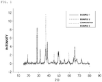
- the pattern of the peak in Example 1 and Example 2 and the pattern of the peak in Comparative Example 2 are generally different from each other.
- Example 1 since the value in Example 1 appears almost the same as in Example 2, the lines overlap and do not appear clearly on the graph.
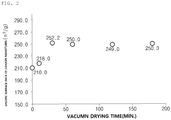
- FIG. 2 shows a change in specific surface area of carbon nanotubes according to vacuum drying time when preparing a supported catalyst in Example 2 while varying the vacuum drying time.
- Example 2 2 wt% of carbon nanotubes in Example 1 and Comparative Example 1, 97.6 wt% of N-methyl-2-pyrrolidone (NMP), and 0.4 wt% of polyvinylpyrrolidone (PVP) were introduced into a high pressure homogenizer (product name: Panda, manufacturer: GEA) and treated at 1,500 bar for 30 minutes to prepare a conductive material dispersion.
- NMP N-methyl-2-pyrrolidone
- PVP polyvinylpyrrolidone
- Viscosity of the conductive material dispersion was measured at 12 rpm, 25°C using a viscometer (model name: DV2T Viscometer, manufacturer: Brookfield, Pin No: 64), the results are shown in Table 2 below.
- electrode slurry including 0.5 wt% of a conductive material dispersion, 98 wt% of LiNi 0.6 Mn 0.2 Co 0.2 O 2 , and 1.5 wt% of polyvinylidene fluoride (PVDF) was prepared, followed by drying at 150°C for 6 hours to prepare powder.
- PVDF polyvinylidene fluoride
- Powder resistance was measured at 64 MPa with 5 g of powder using MCP-PD51 (model name, manufacturer: Mitsubishi Chemical).
- Example 1 As shown in Table 2, the conductive material dispersion in Example 1 was higher in viscosity than the conductive material dispersion in Comparative Example 1. These results are inferred from the facts that the carbon nanotubes in Example 1 have the smaller unit diameter, the larger specific surface area, and the greater number of units contained per unit mass of the powder, compared to the carbon nanotubes in Comparative Example 1. In addition, it was confirmed that the powder in Example 1 using the carbon nanotubes is significantly lower in resistance compared to the powder in Comparative Example 1 because the electrical networking is well made.
- Carbon nanotubes as used herein have a secondary structure shape formed by gathering all or part of carbon nanotube unit cells, and the carbon nanotube unit cell has a graphite sheet having a cylinder shape having a nano size diameter, and sp 2 bonding structure. In this case, characteristics of a conductor or a semiconductor may exhibit depending on the angle and structure in which the graphite sheet is rolled.
- Carbon nanotube unit cells can be divided into single-walled carbon nanotubes (SWCNTs), double-walled carbon nanotubes (DWCNTs) and multi-walled carbon nanotubes (MWCNTs), depending on the number of bonds that form the walls. The thinner the wall, the lower the resistance.
- SWCNTs single-walled carbon nanotubes
- DWCNTs double-walled carbon nanotubes
- MWCNTs multi-walled carbon nanotubes
- the carbon nanotubes of the present invention may include any one or two or more of single-walled, double-walled, and multi-walled carbon nanotube unit cells.
- the term “bundle type” refers to a secondary structure shape in the form of a bundle or a rope, in which a plurality of carbon nanotube unit cells are arranged side by side along the orientation to which the longitudinal axes of the unit cells are substantially identical, or twisted or entangled after being arranged.
- entangled type may refer to a form in which a plurality of carbon nanotube unit cells are entangled without a constant shape, such as a bundle or a rope shape.
- the average particle diameter of the carbon nanotube unit cells herein may be measured using SEM and BET.
- the specific surface area of the carbon nanotubes herein may be measured by the BET method. Specifically, the specific surface area can be calculated from the nitrogen gas adsorption amount under the liquid nitrogen temperature (77K) using BELSORP-mini II (product name, manufacturer: BEL Japan, Inc.).
- a method for preparing carbon nanotubes includes: 1) preparing a support including AIO(OH) by primary heat treatment of Al(OH) 3 ; 2) preparing an active carrier by supporting a mixture including a main catalyst precursor and a cocatalyst precursor on the support; 3) drying the active carrier through multi-stage drying including vacuum drying; 4) preparing a supported catalyst by secondary heat treatment of the dried active support; and 5) preparing carbon nanotubes in the presence of the supported catalyst.
- Al(OH) 3 is primarily heat-treated to prepare a support including AIO(OH).
- a support including mesopores which are easy to carry a catalyst is prepared, and in the subsequent process, a main catalyst and a cocatalyst are well dispersed in the support, thereby preparing carbon nanotubes having a high specific surface area.
- the primary heat treatment may be carried out at 100 to 500°C, and preferably at 200 to 400°C .
- Al(OH) 3 is converted to Al 2 O 3 while the support contains 30 wt% or more of AIO(OH) converted from Al(OH) 3 with respect to the total weight. This enables to produce a support capable of preparing not entangled carbon nanotubes but only a carbon nanotube bundle.
- a mixture including a main catalyst precursor and a cocatalyst precursor is supported on the support to prepare an active carrier.
- the mixture may further include a solvent, and the main catalyst precursor and the cocatalyst precursor may be in a solution state dissolved in a solvent.
- the solvent may be at least one selected from the group consisting of water, methanol and ethanol, wherein the water is preferred.
- the main catalyst may be at least one selected from the group consisting of cobalt, iron, nickel, manganese and chromium, wherein the cobalt is preferred.
- the main catalyst precursor may be at least one selected from the group consisting of nitrates, sulfates, carbonates and acetates of the main catalyst, wherein the nitrate of the main catalyst is preferred.
- the cocatalyst improves dispersibility of the main catalyst, may be vanadium, and may be vanadium and molybdenum.
- the cocatalyst precursor may be at least one selected from the group consisting of NH 4 VO 3 , NaVO 3 , V 2 O 5 , V(C 5 H 7 O 2 ) 3 , (NH 4 ) 6 Mo 7 O 24 , and (NH 4 ) 6 Mo 7 O 24 ⁇ 4H 2 O, wherein at least one selected from the group consisting of NH 4 VO 3 and (NH 4 ) 6 Mo 7 O 24 is preferred.
- the mixture may include the main catalyst precursor and the cocatalyst precursor such that the molar ratio of the main catalyst and the cocatalyst is 40:1 to 3:1, and preferably 15:1 to 5:1.
- the dispersibility of the main catalyst may be remarkably improved.
- the acid point of the surface of the support is controlled by using the cocatalyst to effectively support the main catalyst in a well dispersed form.
- the mixture may further include an organic acid that serves to inhibit precipitation of the main catalyst precursor and the cocatalyst precursor and control the surface charge of the support by adjusting the pH of the solution.
- the organic acid may be at least one selected from the group consisting of citric acid, tartaric acid, fumaric acid, malic acid, acetic acid, butyric acid, palmitic acid and oxalic acid, wherein citric acid is preferred.
- the mixture may include the organic acid and the cocatalyst precursor in a weight ratio of 1:0.2 to 1:2, and preferably include 1:0.5 to 1:1.5.
- a method for preparing carbon nanotubes according to an embodiment of the present invention may further include an aging step after step 2.
- the aging may be carried out for 1 to 60 minutes, preferably 10 to 50 minutes.
- the main catalyst precursor and the cocatalyst precursor may be sufficiently supported on the support.
- bubbles which are present in the support may be removed as much as possible, such that the main catalyst precursor and the cocatalyst precursor may be sufficiently supported to the fine pores inside the support.
- the active carrier is dried through multi-stage drying including vacuum drying.
- the multi-stage drying may mean that a drying process including vacuum drying is performed two or more times.
- the multi-stage drying may mean including atmospheric pressure drying and vacuum drying, or including two or more times of vacuum drying only.
- the main catalyst precursor present in the active support, that is, the coordination compound of the main catalyst is easily decomposed, but also the main catalyst precursor may be converted into the main catalyst oxide having a very small and uniform average particle diameter.
- the main catalyst derived from the main catalyst oxide is present in a very small and uniform average particle diameter in the supported catalyst, and carbon nanotube unit cells grown from the main catalyst has a very small average diameter, so that the amount present per unit area is remarkably increased. If such carbon nanotubes are applied to a conductive material dispersion, the conductivity of the conductive material dispersion may be significantly improved.
- the productivity of the supported catalyst may be improved.
- the vacuum drying may be carried out at 175 to 300°C , and preferably at 180 to 280°C .
- the main catalyst precursor that is, the coordination compound of the main catalyst may be easily decomposed to form the main catalyst oxide, and the energy consumption may be minimized.
- the vacuum drying may be carried out at 1 to 200 mbar, and preferably at 1 to 100 mbar.
- the main catalyst precursor that is, the coordination compound of the main catalyst is suddenly decomposed and discharged, so that the main catalyst oxide may be more easily formed under vacuum conditions, and the energy consumption may be minimized.
- the vacuum drying may be carried out for 10 minutes to 3 hours, preferably 10 minutes to 2 hours.
- the main catalyst precursor may be easily decomposed and converted into the main catalyst oxide, and the energy consumption may be minimized.
- the atmospheric pressure drying may be performed before the above-mentioned vacuum drying is performed, and the solvent which may exist in the active carrier may be removed by the atmospheric pressure drying.
- the atmospheric pressure drying may be carried out at 80 to 160°C , and preferably at 100 to 140°C.
- the solvent present in the active carrier may be sufficiently removed, and the energy consumption may be minimized.
- the atmospheric pressure drying may be carried out at 900 to 1,100 mbar, and preferably at 950 to 1,050 mbar.
- the solvent present in the active carrier may be sufficiently removed, and the energy consumption may be minimized.
- the atmospheric pressure drying may be carried out for 1 to 12 hours, preferably 3 to 9 hours.
- the solvent present in the active carrier may be sufficiently removed, and the energy consumption may be minimized.
- the multi-stage drying may include two or more times of vacuum drying which are carried out at a different temperature, more specifically, a primary vacuum drying performed at a first temperature and a secondary vacuum drying performed at a second temperature higher than the first temperature.
- the primary vacuum drying may be carried out to remove a solvent that may be present in the active carrier.
- the first temperature may be 80 to 160°C, and preferably 100 to 140°C.
- the solvent present in the active carrier may be sufficiently removed, and the energy consumption may be minimized.
- the primary vacuum drying may be carried out for 1 to 12 hours, and preferably 3 to 9 hours.
- the solvent present in the active carrier may be sufficiently removed, and the energy consumption may be minimized.
- the primary vacuum drying may be carried out at 1 to 200 mbar, and preferably at 1 to 150 mbar.
- the solvent present in the active carrier may be sufficiently removed, and the energy consumption may be minimized.
- the second temperature may be 175 to 300°C, and preferably 180 to 280°C.
- the main catalyst precursor that is, the coordination compound of the main catalyst may be easily decomposed to form the main catalyst oxide, and the energy consumption may be minimized.
- the secondary vacuum drying may be carried out at 1 to 200 mbar, preferably at 1 to 150 mbar, and more preferably at 1 to 100 mbar.
- the main catalyst precursor that is, the coordination compound of the main catalyst is suddenly decomposed and discharged, so that the main catalyst oxide may be more easily formed under vacuum conditions, and the energy consumption may be minimized.
- the secondary vacuum drying may be carried out for 10 minutes to 3 hours, and preferably 10 minutes to 2 hours.
- the main catalyst precursor may be easily decomposed and converted into the main catalyst oxide, and the energy consumption may be minimized.
- the dried active carrier is subjected to secondary heat treatment to prepare a supported catalyst.
- a supported catalyst is prepared in a state in which the main catalyst and the cocatalyst are coated on the surface and the pores of the support.
- the secondary heat treatment may be carried out at 600 to 800°C, and preferably at 620 to 750°C.
- the supported catalyst may be prepared in a state in which the main catalyst and the promoter are uniformly coated on the surface and the pores of the support, and energy consumption may be minimized.
- the secondary heat treatment may be carried out for 1 to 12 hours, and preferably 2 to 8 hours.
- the supported catalyst may be prepared in a state in which the catalyst precursor is uniformly coated on the surface and the pores of the support.
- carbon nanotubes may be prepared by contacting the supported catalyst with a carbon-based compound, and specifically, a chemical vapor phase synthesis method may be carried out.
- the supported catalyst may be introduced into a horizontal fixed bed reactor or a fluidized bed reactor.
- carbon nanotubes may be grown by the chemical vapor phase synthesis method through decomposing the gaseous carbon-based compound by injecting the gaseous carbon-based compound or the gaseous carbon-based compound and a mixed gas of a reducing gas (e.g., hydrogen) and a carrier gas (e.g., nitrogen) at above a pyrolysis temperature of the gaseous carbon-based compound or a temperature below the melting point of catalyst which is supported the supported catalyst.
- a reducing gas e.g., hydrogen
- a carrier gas e.g., nitrogen
- Carbon nanotubes prepared by the chemical vapor phase synthesis method as described above may have high crystallinity of the graphite structure in the tube length direction and the crystal growth direction is substantially parallel to the tube axis. As a result, carbon nanotubes having a small diameter and high conductivity and strength may be prepared.
- the chemical vapor synthesis method may be carried out at 600 to 800°C, and preferably at 650 to 750°C .
- carbon nanotubes may be prepared while minimizing the generation of amorphous carbon.
- induction heating radiant heat, laser, IR, microwave, plasma, surface plasmon heating and the like may be used.
- the carbon-based compound may supply carbon and whatever carbon-based compound can exist in a gaseous state at a temperature of 300°C or higher may be used without particular limitation.
- the carbon-based compound may be a carbon-based compound having 6 or less of carbon atoms, and at least one selected from the group consisting of carbon monoxide, methane, ethane, ethylene, ethanol, acetylene, propane, propylene, butane, butadiene, pentane, pentene, cyclopentadiene, hexane, cyclohexane, benzene, and toluene.
- a cooling process for more regularly aligning the arrangement of the carbon nanotubes may optionally be further performed.
- the cooling process may be performed using natural cooling according to the removal of the heat source or a cooler.
- the carbon nanotubes may be in a bundle type.
- Carbon nanotubes prepared by the preparing method according to an embodiment of the present invention include carbon nanotube units having an average diameter of 5 to 20 nm.
- the carbon nanotubes preferably include carbon nanotube units having an average diameter of 8 to 15 nm.
- the number of carbon nanotube units which are present per unit area is remarkably increased, so that the conductivity can be remarkably improved when applied to a conductive material dispersion.
- the carbon nanotubes may have a specific surface area of 200 to 350 m 2 /g, preferably 200 to 300 m 2 /g, and particularly preferably 240 to 280 m 2 /g.
- the specific surface area of carbon nanotubes has a strong negative correlation with the average diameter. As the average diameter of carbon nanotubes decreases, the specific surface area increases. Therefore, if the specific surface area of carbon nanotubes satisfies the above conditions, the number of carbon nanotube units which are present per unit area is remarkably increased, so that the conductivity can be remarkably improved when applied to the conductive material dispersion.
Landscapes
- Chemical & Material Sciences (AREA)
- Engineering & Computer Science (AREA)
- Materials Engineering (AREA)
- Organic Chemistry (AREA)
- Chemical Kinetics & Catalysis (AREA)
- Nanotechnology (AREA)
- Inorganic Chemistry (AREA)
- Physics & Mathematics (AREA)
- Thermal Sciences (AREA)
- Carbon And Carbon Compounds (AREA)
- Catalysts (AREA)
- Inorganic Fibers (AREA)
Abstract
Description
- The present application claims the benefit of the priority of Korean Patent Application No.
10-2018-0088008, filed on July 27, 2018 - The present invention relates to a method for preparing carbon nanotubes, and to a method for preparing carbon nanotubes including drying an active carrier through multi-stage drying including vacuum drying.
- In general, carbon nanotubes refer to cylindrical carbon tubes having a diameter of several nanometers to several tens of nanometers and having a length greater by several times to several ten times than the diameter. These carbon nanotubes consist of layers of aligned carbon atoms.
- Carbon nanotubes may be generally prepared by an arc discharge method, a laser evaporation method, a chemical vapor phase synthesis method, or the like. Among these, the arc discharge method and the laser evaporation method have problems in that it is difficult to mass-produce, and the economic efficiency is lowered due to excessive arc production cost and laser equipment purchase cost.
- Carbon nanotubes exhibit insulator, conductor or semiconductor properties depending on their unique chirality, and the carbon atoms are connected by strong covalent bonds, and thus the carbon nanotubes have tensile strength greater than steel, superior flexibility and elasticity, and chemical stability.
- Such carbon nanotubes can be dispersed in a dispersion medium and used as a conductive material dispersion. When the carbon nanotubes are dispersed at a high concentration in order to improve the conductivity of the conductive material dispersion, it becomes difficult to handle the same due to the increase in viscosity.
- Accordingly, research has been continued to improve the conductivity of the conductive material dispersion without increasing the concentration of carbon nanotubes.
- (Patent Document 1)
KR10-1431953B - An aspect of the present invention provides a method for preparing carbon nanotubes with significantly improved conductivity.
- To solve the problems, the present invention provides a method for preparing carbon nanotubes, the method including: preparing a support including AlO(OH) by primary heat treatment of Al(OH)3; preparing an active carrier by supporting a mixture including a main catalyst precursor and a cocatalyst precursor on the support; drying the active carrier through multi-stage drying including vacuum drying; preparing a supported catalyst by secondary heat treatment of the dried active support; and preparing carbon nanotubes in the presence of the supported catalyst.
- In addition, the present invention provides carbon nanotubes which are prepared according to the above-described preparing method, and include a carbon nanotube unit having an average diameter of 5-20 nm.
- According to a method for preparing carbon nanotubes of the present invention, since carbon nanotube units having a small average diameter can be prepared, the number of carbon nanotube units per unit area is significantly increased.
- Since the carbon nanotubes prepared by the method for preparing the carbon nanotubes of the present invention are in a bundle type, the carbon nanotubes may be applied to a conductive material dispersion, and the conductivity of the conductive material dispersion may be significantly improved.
-
-
FIG. 1 is a graph measuring the XRD patterns of supported catalysts prepared in Example 1, Example 2, and Comparative Example 2. -
FIG. 2 is a graph showing a change in specific surface area of carbon nanotubes according to vacuum drying time when preparing a supported catalyst in Example 2 while varying the vacuum drying time. - Hereinafter, embodiments of the present invention will be described in detail so that a person with ordinary skill in the art can easily practice the present invention. The present invention may, however, be embodied in different forms and should not be construed as limited to the embodiments set forth herein.
- Al(OH)3 (30 g, product name: BH39-622, manufacturer: Nippon Light Metal Holdings Co., Ltd., Japan) was primarily heat-treated at 400°C for 4 hours to prepare a support. Co(NO3)2·6H2O (15.7 g) as a main catalyst precursor, NH4VO3 (0.63 g) as a cocatalyst precursor, a citric acid (0.45 g) and distilled water (20 ml) were added to prepare a catalyst precursor solution. The entire amount of the catalyst precursor solution was supported on the support (20 mg) to prepare an active carrier. The active carrier was aged while being stirred for 15 minutes in a thermostat at 80°C.
- The aged active support was then primarily vacuum dried at 120°C, 100 mbar for 120 minutes. The primarily vacuum dried active carrier was secondarily vacuum dried while rotating at 200°C, 10 mbar for 30 minutes. The secondarily vacuum dried active carrier was secondarily heat-treated at 700°C for 2 hours to prepare a supported catalyst.
- The obtained supported catalyst (1 g) was mounted on the bottom of a quartz tube having an internal diameter of 55 mm located in the fluidized bed reactor. The inside of the fluidized bed reactor was heated at a constant rate up to 660°C in a nitrogen atmosphere, and then maintained, and synthesized for 90 hours while flowing nitrogen gas and ethylene gas in a volume ratio of 3:1 at 2.1 1/min to prepare 21 g of carbon nanotubes.
- The preparation of nanotubes in Example 2 was performed under all the same conditions as those in Example 1 except that Co(NO3)2·6H2O (14.13 g) as the main catalyst precursor, NH4VO3 (0.85 g) as the cocatalyst precursor, (NH4)6Mo7O24 (0.255 g), citric acid (0.61 g) and distilled water (20 ml) were added to prepare a catalyst precursor solution.
- The supported catalyst and carbon nanotubes were prepared in the same manner as in Example 1 except that the primary vacuum dried active carrier was secondary vacuum dried while rotating at 175°C, 50 mbar for 1 hour.
- The supported catalyst and carbon nanotubes were prepared in the same manner as in Example 1 except that the primarily vacuum dried active carrier was secondarily vacuum dried while rotating at 300°C, 10 mbar for 30 minutes.
- The supported catalyst and carbon nanotubes were prepared in the same manner as in Example 1 except that the primarily vacuum dried active carrier was secondarily vacuum dried while rotating at 200°C, 50 mbar for 30 minutes.
- The supported catalyst and carbon nanotubes were prepared in the same manner as in Example 1 except that the primarily vacuum dried active support was secondarily vacuum dried while rotating at 170°C, 10 mbar for 30 minutes.
- The supported catalyst and carbon nanotubes were prepared in the same manner as in Example 1 except that the primarily vacuum dried active carrier was not subjected to secondary vacuum drying but dried at atmospheric pressure at 200°C for 2 hours.
- The supported catalyst and carbon nanotubes were prepared in the same manner as in Example 1 except that the primarily vacuum dried active carrier was not subjected to secondary vacuum drying but dried at atmospheric pressure at 200°C for 2 hours with the vessel lid being closed.
- Physical properties of the supported catalysts prepared in Examples 1 and 2 and Comparative Example 2 were measured by the methods described below, and the results are shown in
FIG. 1 and Table 1 below. - ① XRD pattern and catalyst crystallinity: XRD pattern and catalyst crystallinity were measured under the following conditions.
- Bruker AXS D4 Endeavor XRD (voltage: 40 kV, current: 40 mA)
- Cu Kα radiation (wavelength: 1.54 Å)
- LynxEye position sensitive detector (3.7° slit)
- Referring to
FIG. 1 , it was confirmed that the maximum diffraction peak intensity in Example 1 and Example 2 was obtained at 2θ value = 25° to 30°, whereas the maximum diffraction peak in Comparative Example 2 was obtained at 35° to 40°. In addition, it was seen that the pattern of the peak in Example 1 and Example 2 and the pattern of the peak in Comparative Example 2 are generally different from each other. - From such results, it was confirmed that the supported catalysts in Examples 1 and 2 and the supported catalysts in Comparative Example 2 had different physical properties.
- On the other hand, since the value in Example 1 appears almost the same as in Example 2, the lines overlap and do not appear clearly on the graph.
-
FIG. 2 shows a change in specific surface area of carbon nanotubes according to vacuum drying time when preparing a supported catalyst in Example 2 while varying the vacuum drying time. - Referring to
FIG. 2 , it was seen that when the vacuum drying time is 30 minutes or less, as the vacuum drying time elapses, the specific surface area of the carbon nanotubes increases which are prepared as the supported catalyst. In addition, since the decomposition of the main catalyst precursor starts from the vacuum drying time of 30 minutes or more, it was confirmed that the specific surface area of the carbon nanotubes was maintained relatively constant. - Physical properties of the carbon nanotubes of Examples and Comparative Examples were measured by the methods described below, and the results are shown in Table 2 below.
- ② Secondary structure shape was observed using a scanning electron microscope.
- ③ Average diameter (nm) of carbon nanotube unit was measured using SEM and BET.
- ④ Specific surface area (m2/g) was measured by BET method using BELSORP-mini II (product name, manufacturer: BEL Japan, Inc.).
- [Table 1]
Division Catalyst crystallinity (I37°/I72°) Secondary structure shape Average diameter of carbon nanotube unit Specific surface area Example 1 3.4 Bundle type 8.6 256 Example 2 3.5 Bundle type 8.4 254 Example 3 4.3 Bundle type 10.2 244 Example 4 3.1 Bundle type 8.0 262 Example 5 3.6 Bundle type 8.8 252 Example 6 5.2 Bundle type 15.5 223 Comparative Example 1 8.5 Bundle + Entangled type 18.4 205.7 Comparative Example 2 11.5 Bundle + Entangled type 20.4 185 - Referring to Table 1, it was confirmed that compared to the carbon nanotubes in Comparative Examples 1 and 2, the carbon nanotubes in Examples 1 to 6 in which the supported catalysts have lower crystallinity the secondary structure shape is the bundle type, and the units have smaller average diameters were prepared. However, in Comparative Examples 1 and 2, which were not subjected to vacuum drying when preparing the supported catalysts, it was confirmed that the supported catalysts have large crystallinity, and thus, the carbon nanotubes having a mixed state of a Bundle type and an Entangled type, and of which the units have a large average diameter were prepared.
- 2 wt% of carbon nanotubes in Example 1 and Comparative Example 1, 97.6 wt% of N-methyl-2-pyrrolidone (NMP), and 0.4 wt% of polyvinylpyrrolidone (PVP) were introduced into a high pressure homogenizer (product name: Panda, manufacturer: GEA) and treated at 1,500 bar for 30 minutes to prepare a conductive material dispersion.
- Viscosity of the conductive material dispersion was measured at 12 rpm, 25°C using a viscometer (model name: DV2T Viscometer, manufacturer: Brookfield, Pin No: 64), the results are shown in Table 2 below.
- In addition, electrode slurry including 0.5 wt% of a conductive material dispersion, 98 wt% of LiNi0.6Mn0.2Co0.2O2, and 1.5 wt% of polyvinylidene fluoride (PVDF) was prepared, followed by drying at 150°C for 6 hours to prepare powder.
- Powder resistance was measured at 64 MPa with 5 g of powder using MCP-PD51 (model name, manufacturer: Mitsubishi Chemical).
- [Table 2]
Division Viscosity of conductive material dispersion (cP) Powder Resistance (Q-cm) Example 1 12,000 48 Comparative Example 2 8,500 125 - As shown in Table 2, the conductive material dispersion in Example 1 was higher in viscosity than the conductive material dispersion in Comparative Example 1. These results are inferred from the facts that the carbon nanotubes in Example 1 have the smaller unit diameter, the larger specific surface area, and the greater number of units contained per unit mass of the powder, compared to the carbon nanotubes in Comparative Example 1. In addition, it was confirmed that the powder in Example 1 using the carbon nanotubes is significantly lower in resistance compared to the powder in Comparative Example 1 because the electrical networking is well made.
- Hereinafter, the present invention will be described in more detail to aid in understanding the present invention.
- Terms or words used in this specification and claims should not be restrictively interpreted as ordinary meanings or dictionary-based meanings, but should be interpreted as meanings and concepts conforming to the scope of the present invention on the basis of the principle that an inventor can properly define the concept of a term to describe and explain his or her invention in the best ways.
- "Carbon nanotubes" as used herein have a secondary structure shape formed by gathering all or part of carbon nanotube unit cells, and the carbon nanotube unit cell has a graphite sheet having a cylinder shape having a nano size diameter, and sp2 bonding structure. In this case, characteristics of a conductor or a semiconductor may exhibit depending on the angle and structure in which the graphite sheet is rolled.
- Carbon nanotube unit cells can be divided into single-walled carbon nanotubes (SWCNTs), double-walled carbon nanotubes (DWCNTs) and multi-walled carbon nanotubes (MWCNTs), depending on the number of bonds that form the walls. The thinner the wall, the lower the resistance.
- The carbon nanotubes of the present invention may include any one or two or more of single-walled, double-walled, and multi-walled carbon nanotube unit cells.
- As used herein, unless mentioned otherwise, the term "bundle type" refers to a secondary structure shape in the form of a bundle or a rope, in which a plurality of carbon nanotube unit cells are arranged side by side along the orientation to which the longitudinal axes of the unit cells are substantially identical, or twisted or entangled after being arranged.
- As used herein, unless mentioned otherwise, the term "entangled type" may refer to a form in which a plurality of carbon nanotube unit cells are entangled without a constant shape, such as a bundle or a rope shape.
- The average particle diameter of the carbon nanotube unit cells herein may be measured using SEM and BET.
- The specific surface area of the carbon nanotubes herein may be measured by the BET method. Specifically, the specific surface area can be calculated from the nitrogen gas adsorption amount under the liquid nitrogen temperature (77K) using BELSORP-mini II (product name, manufacturer: BEL Japan, Inc.).
- A method for preparing carbon nanotubes according to an embodiment of the present invention includes: 1) preparing a support including AIO(OH) by primary heat treatment of Al(OH)3; 2) preparing an active carrier by supporting a mixture including a main catalyst precursor and a cocatalyst precursor on the support; 3) drying the active carrier through multi-stage drying including vacuum drying; 4) preparing a supported catalyst by secondary heat treatment of the dried active support; and 5) preparing carbon nanotubes in the presence of the supported catalyst.
- Hereinafter, a method for preparing carbon nanotubes according to an embodiment of the present invention will be described in detail.
- First, Al(OH)3 is primarily heat-treated to prepare a support including AIO(OH).
- When the primary heat treatment is carried out, a support including mesopores which are easy to carry a catalyst is prepared, and in the subsequent process, a main catalyst and a cocatalyst are well dispersed in the support, thereby preparing carbon nanotubes having a high specific surface area.
- The primary heat treatment may be carried out at 100 to 500°C, and preferably at 200 to 400°C .
- If the above conditions are satisfied, it may be prevented that Al(OH)3 is converted to Al2O3 while the support contains 30 wt% or more of AIO(OH) converted from Al(OH)3 with respect to the total weight. This enables to produce a support capable of preparing not entangled carbon nanotubes but only a carbon nanotube bundle.
- Subsequently, a mixture including a main catalyst precursor and a cocatalyst precursor is supported on the support to prepare an active carrier.
- In order to prepare an active carrier in which the main catalyst precursor and the cocatalyst precursor are uniformly supported on the support, the mixture may further include a solvent, and the main catalyst precursor and the cocatalyst precursor may be in a solution state dissolved in a solvent. The solvent may be at least one selected from the group consisting of water, methanol and ethanol, wherein the water is preferred.
- The main catalyst may be at least one selected from the group consisting of cobalt, iron, nickel, manganese and chromium, wherein the cobalt is preferred.
- The main catalyst precursor may be at least one selected from the group consisting of nitrates, sulfates, carbonates and acetates of the main catalyst, wherein the nitrate of the main catalyst is preferred.
- The main catalyst precursor may be at least one selected from the group consisting of Co(NO3)2, Co(NO3)2·6H2O, CO2(CO)8, Co2(CO)6[HC=C(C(CH3)3)], Co(CH3CO2)2, Fe(NO3)3, Fe(NO3)2·nH2O, Fe(CH3CO2)2, Ni(NO3)2, Ni(NO3)2·6H2O, Mn(NO3)2, Mn(NO3)2·6H2O, Mn(CH3CO2)2·n(H2O) and Mn(CO)5Br, wherein at least one selected from the group consisting of Co(NO3)2·6H2O, Fe(NO3)2·nH2O, and Ni(NO3)2·6H2O is preferred.
- The cocatalyst improves dispersibility of the main catalyst, may be vanadium, and may be vanadium and molybdenum.
- The cocatalyst precursor may be at least one selected from the group consisting of NH4VO3, NaVO3, V2O5, V(C5H7O2)3, (NH4) 6Mo7O24, and (NH4) 6Mo7O24·4H2O, wherein at least one selected from the group consisting of NH4VO3 and (NH4)6Mo7O24 is preferred.
- The mixture may include the main catalyst precursor and the cocatalyst precursor such that the molar ratio of the main catalyst and the cocatalyst is 40:1 to 3:1, and preferably 15:1 to 5:1.
- If the above molar ratio is satisfied, the dispersibility of the main catalyst may be remarkably improved. In addition, when the catalyst is supported, the acid point of the surface of the support is controlled by using the cocatalyst to effectively support the main catalyst in a well dispersed form.
- The mixture may further include an organic acid that serves to inhibit precipitation of the main catalyst precursor and the cocatalyst precursor and control the surface charge of the support by adjusting the pH of the solution.
- The organic acid may be at least one selected from the group consisting of citric acid, tartaric acid, fumaric acid, malic acid, acetic acid, butyric acid, palmitic acid and oxalic acid, wherein citric acid is preferred.
- The mixture may include the organic acid and the cocatalyst precursor in a weight ratio of 1:0.2 to 1:2, and preferably include 1:0.5 to 1:1.5.
- When the above-mentioned range is satisfied, after supporting, fine powder production due to precipitation of the main catalyst and the cocatalyst may be suppressed, and as a result, there is an advantage that a transparent mixture in a solution state including the main catalyst and the cocatalyst is prepared. If precipitation occurs in the mixture in a solution state, the main catalyst and the cocatalyst may not be uniformly coated on the support, and thus, a heterogeneous supported catalyst may be prepared. In addition, the heterogeneous supported catalyst may generate a lot of fine powder during growth of carbon nanotubes, which may cause troubles during the preparing process of carbon nanotubes.
- A method for preparing carbon nanotubes according to an embodiment of the present invention may further include an aging step after
step 2. - The aging may be carried out for 1 to 60 minutes, preferably 10 to 50 minutes.
- When the above conditions are satisfied, the main catalyst precursor and the cocatalyst precursor may be sufficiently supported on the support. In addition, bubbles which are present in the support may be removed as much as possible, such that the main catalyst precursor and the cocatalyst precursor may be sufficiently supported to the fine pores inside the support.
- Subsequently, the active carrier is dried through multi-stage drying including vacuum drying.
- The multi-stage drying may mean that a drying process including vacuum drying is performed two or more times. Specifically, the multi-stage drying may mean including atmospheric pressure drying and vacuum drying, or including two or more times of vacuum drying only.
- By performing the vacuum drying, not only the main catalyst precursor present in the active support, that is, the coordination compound of the main catalyst is easily decomposed, but also the main catalyst precursor may be converted into the main catalyst oxide having a very small and uniform average particle diameter. In addition, the main catalyst derived from the main catalyst oxide is present in a very small and uniform average particle diameter in the supported catalyst, and carbon nanotube unit cells grown from the main catalyst has a very small average diameter, so that the amount present per unit area is remarkably increased. If such carbon nanotubes are applied to a conductive material dispersion, the conductivity of the conductive material dispersion may be significantly improved.
- In addition, since the main catalyst precursor is easily decomposed by the vacuum drying, the productivity of the supported catalyst may be improved.
- The vacuum drying may be carried out at 175 to 300°C , and preferably at 180 to 280°C .
- When the above conditions are satisfied, the main catalyst precursor, that is, the coordination compound of the main catalyst may be easily decomposed to form the main catalyst oxide, and the energy consumption may be minimized.
- The vacuum drying may be carried out at 1 to 200 mbar, and preferably at 1 to 100 mbar.
- When the above conditions are satisfied, the main catalyst precursor, that is, the coordination compound of the main catalyst is suddenly decomposed and discharged, so that the main catalyst oxide may be more easily formed under vacuum conditions, and the energy consumption may be minimized.
- The vacuum drying may be carried out for 10 minutes to 3 hours, preferably 10 minutes to 2 hours.
- When the above conditions are satisfied, the main catalyst precursor may be easily decomposed and converted into the main catalyst oxide, and the energy consumption may be minimized.
- Meanwhile, when the multi-stage drying includes atmospheric pressure drying and vacuum drying, the atmospheric pressure drying may be performed before the above-mentioned vacuum drying is performed, and the solvent which may exist in the active carrier may be removed by the atmospheric pressure drying.
- The atmospheric pressure drying may be carried out at 80 to 160°C , and preferably at 100 to 140°C.
- When the above conditions are satisfied, the solvent present in the active carrier may be sufficiently removed, and the energy consumption may be minimized.
- The atmospheric pressure drying may be carried out at 900 to 1,100 mbar, and preferably at 950 to 1,050 mbar.
- When the above conditions are satisfied, the solvent present in the active carrier may be sufficiently removed, and the energy consumption may be minimized.
- The atmospheric pressure drying may be carried out for 1 to 12 hours, preferably 3 to 9 hours.
- When the above conditions are satisfied, the solvent present in the active carrier may be sufficiently removed, and the energy consumption may be minimized.
- On the other hand, when the multi-stage drying includes two or more times of vacuum drying only, the multi-stage drying may include two or more times of vacuum drying which are carried out at a different temperature, more specifically, a primary vacuum drying performed at a first temperature and a secondary vacuum drying performed at a second temperature higher than the first temperature.
- The primary vacuum drying may be carried out to remove a solvent that may be present in the active carrier.
- The first temperature may be 80 to 160°C, and preferably 100 to 140°C.
- When the above conditions are satisfied, the solvent present in the active carrier may be sufficiently removed, and the energy consumption may be minimized.
- The primary vacuum drying may be carried out for 1 to 12 hours, and preferably 3 to 9 hours.
- When the above conditions are satisfied, the solvent present in the active carrier may be sufficiently removed, and the energy consumption may be minimized.
- The primary vacuum drying may be carried out at 1 to 200 mbar, and preferably at 1 to 150 mbar.
- When the above conditions are satisfied, the solvent present in the active carrier may be sufficiently removed, and the energy consumption may be minimized.
- The description of the secondary vacuum drying is as described in the above description of the vacuum drying.
- The second temperature may be 175 to 300°C, and preferably 180 to 280°C.
- When the above conditions are satisfied, the main catalyst precursor, that is, the coordination compound of the main catalyst may be easily decomposed to form the main catalyst oxide, and the energy consumption may be minimized.
- The secondary vacuum drying may be carried out at 1 to 200 mbar, preferably at 1 to 150 mbar, and more preferably at 1 to 100 mbar.
- When the above conditions are satisfied, the main catalyst precursor, that is, the coordination compound of the main catalyst is suddenly decomposed and discharged, so that the main catalyst oxide may be more easily formed under vacuum conditions, and the energy consumption may be minimized.
- The secondary vacuum drying may be carried out for 10 minutes to 3 hours, and preferably 10 minutes to 2 hours.
- When the above conditions are satisfied, the main catalyst precursor may be easily decomposed and converted into the main catalyst oxide, and the energy consumption may be minimized.
- Subsequently, the dried active carrier is subjected to secondary heat treatment to prepare a supported catalyst.
- When the secondary heat treatment is performed, a supported catalyst is prepared in a state in which the main catalyst and the cocatalyst are coated on the surface and the pores of the support.
- The secondary heat treatment may be carried out at 600 to 800°C, and preferably at 620 to 750°C.
- When the above conditions are satisfied, the supported catalyst may be prepared in a state in which the main catalyst and the promoter are uniformly coated on the surface and the pores of the support, and energy consumption may be minimized.
- The secondary heat treatment may be carried out for 1 to 12 hours, and preferably 2 to 8 hours.
- When the above time condition is satisfied, the supported catalyst may be prepared in a state in which the catalyst precursor is uniformly coated on the surface and the pores of the support.
- Subsequently, in the presence of the supported catalyst, a step for preparing carbon nanotubes is performed.
- Particularly, carbon nanotubes may be prepared by contacting the supported catalyst with a carbon-based compound, and specifically, a chemical vapor phase synthesis method may be carried out.
- The step for preparing carbon nanotubes will be described in detail. First, the supported catalyst may be introduced into a horizontal fixed bed reactor or a fluidized bed reactor. Subsequently, carbon nanotubes may be grown by the chemical vapor phase synthesis method through decomposing the gaseous carbon-based compound by injecting the gaseous carbon-based compound or the gaseous carbon-based compound and a mixed gas of a reducing gas (e.g., hydrogen) and a carrier gas (e.g., nitrogen) at above a pyrolysis temperature of the gaseous carbon-based compound or a temperature below the melting point of catalyst which is supported the supported catalyst.
- Carbon nanotubes prepared by the chemical vapor phase synthesis method as described above may have high crystallinity of the graphite structure in the tube length direction and the crystal growth direction is substantially parallel to the tube axis. As a result, carbon nanotubes having a small diameter and high conductivity and strength may be prepared.
- The chemical vapor synthesis method may be carried out at 600 to 800°C, and preferably at 650 to 750°C .
- When the above temperature condition is satisfied, carbon nanotubes may be prepared while minimizing the generation of amorphous carbon.
- As a heat source for the reaction, induction heating, radiant heat, laser, IR, microwave, plasma, surface plasmon heating and the like may be used.
- In addition, the carbon-based compound may supply carbon and whatever carbon-based compound can exist in a gaseous state at a temperature of 300°C or higher may be used without particular limitation.
- The carbon-based compound may be a carbon-based compound having 6 or less of carbon atoms, and at least one selected from the group consisting of carbon monoxide, methane, ethane, ethylene, ethanol, acetylene, propane, propylene, butane, butadiene, pentane, pentene, cyclopentadiene, hexane, cyclohexane, benzene, and toluene.
- After growing the carbon nanotubes by the above-described reaction, a cooling process for more regularly aligning the arrangement of the carbon nanotubes may optionally be further performed. Specifically, the cooling process may be performed using natural cooling according to the removal of the heat source or a cooler.
- The carbon nanotubes may be in a bundle type.
- Carbon nanotubes prepared by the preparing method according to an embodiment of the present invention include carbon nanotube units having an average diameter of 5 to 20 nm.
- The carbon nanotubes preferably include carbon nanotube units having an average diameter of 8 to 15 nm.
- If the above conditions are satisfied, the number of carbon nanotube units which are present per unit area is remarkably increased, so that the conductivity can be remarkably improved when applied to a conductive material dispersion.
- The carbon nanotubes may have a specific surface area of 200 to 350 m2/g, preferably 200 to 300 m2/g, and particularly preferably 240 to 280 m2/g.
- The specific surface area of carbon nanotubes has a strong negative correlation with the average diameter. As the average diameter of carbon nanotubes decreases, the specific surface area increases. Therefore, if the specific surface area of carbon nanotubes satisfies the above conditions, the number of carbon nanotube units which are present per unit area is remarkably increased, so that the conductivity can be remarkably improved when applied to the conductive material dispersion.
Claims (16)
- A method for preparing carbon nanotubes, the method comprising:preparing a support comprising AIO(OH) by primary heat treatment of Al(OH)3;preparing an active carrier by supporting a mixture including a main catalyst precursor and a cocatalyst precursor on the support;drying the active carrier through multi-stage drying including vacuum drying;preparing a supported catalyst by secondary heat treatment of the dried active carrier; andpreparing carbon nanotubes in the presence of the supported catalyst.
- The method of claim 1, wherein the multi-stage drying comprises atmospheric pressure drying and vacuum drying.
- The method of claim 2, wherein the atmospheric pressure drying is carried out at 80 to 160°C.
- The method of claim 1, wherein the vacuum drying is carried out at 175 to 300°C.
- The method of claim 1, wherein the vacuum drying is carried out at 1 to 200 mbar.
- The method of claim 1, wherein the vacuum drying is carried out for 10 minutes to 3 hours.
- The method of claim 1, wherein the multi-stage drying comprises primary vacuum drying which is carried out at a first temperature and secondary vacuum drying which is carried out at a second temperature higher than the first temperature.
- The method of claim 7, wherein the first temperature is from 80 to 160°C.
- The method of claim 7, wherein the second temperature is from 175 to 300°C.
- The method of claim 1, wherein the primary heat treatment is carried out at 100 to 500°C.
- The method of claim 1, wherein the secondary heat treatment is carried out at 600 to 800°C.
- The method of claim 1, wherein the main catalyst precursor is at least one selected from the group consisting of Co(NO3)2, Co (NO3)2·6H2O, CO2(CO)8, Co2(CO)6[HC=C(C(CH3)3)], Co(CH3CO2)2, Fe(NO3)3, Fe(NO3)2·nH2O, Fe(CH3CO2)2, Ni(NO3)2, Ni(NO3)2·6H2O, Mn(NO3)2, Mn(NO3)2·6H2O, Mn(CH3CO2)2·n(H2O), and Mn(CO)5Br.
- The method of claim 1, wherein the cocatalyst precursor is at least one selected from the group consisting of NH4VO3, NaVO3, V2O5, V(C5H7O2)3, (NH4)6MO7O24, and (NH4)6Mo7O24·4H2O.
- The method of claim 1, wherein the carbon nanotubes are in a bundle type.
- Carbon nanotubes prepared according to the method of any one of claims 1 to 14, and
comprising carbon nanotube units having an average diameter of 5 to 20 nm. - The carbon nanotubes of claim 15, wherein the carbon nanotubes have a specific surface area of 200 to 350 m2/g.
Applications Claiming Priority (2)
| Application Number | Priority Date | Filing Date | Title |
|---|---|---|---|
| KR1020180088008A KR102450747B1 (en) | 2018-07-27 | 2018-07-27 | Method for preparing carbonnanotube |
| PCT/KR2019/009042 WO2020022725A1 (en) | 2018-07-27 | 2019-07-22 | Method for preparing carbon nanotubes |
Publications (3)
| Publication Number | Publication Date |
|---|---|
| EP3831774A1 true EP3831774A1 (en) | 2021-06-09 |
| EP3831774A4 EP3831774A4 (en) | 2021-09-29 |
| EP3831774B1 EP3831774B1 (en) | 2025-09-03 |
Family
ID=69181858
Family Applications (1)
| Application Number | Title | Priority Date | Filing Date |
|---|---|---|---|
| EP19840337.0A Active EP3831774B1 (en) | 2018-07-27 | 2019-07-22 | Method for preparing carbon nanotubes |
Country Status (7)
| Country | Link |
|---|---|
| US (1) | US11964870B2 (en) |
| EP (1) | EP3831774B1 (en) |
| JP (1) | JP7086418B2 (en) |
| KR (1) | KR102450747B1 (en) |
| CN (1) | CN112203978B (en) |
| TW (1) | TWI815931B (en) |
| WO (1) | WO2020022725A1 (en) |
Families Citing this family (5)
| Publication number | Priority date | Publication date | Assignee | Title |
|---|---|---|---|---|
| KR102450747B1 (en) * | 2018-07-27 | 2022-10-06 | 주식회사 엘지화학 | Method for preparing carbonnanotube |
| CN116390808B (en) * | 2020-11-09 | 2024-09-27 | 株式会社科本 | Method for continuously synthesizing carbon nano tube |
| CN115254133A (en) * | 2022-05-16 | 2022-11-01 | 湖北冠毓新材料科技有限公司 | Preparation method of supported high-conductivity carbon nanotube catalyst |
| KR20240063802A (en) * | 2022-11-03 | 2024-05-10 | 주식회사 엘지화학 | Catalyst for manufacturing carbon nanotubes and method for preparing the same |
| CN119034823B (en) * | 2024-10-29 | 2025-05-02 | 浙江方泰思克科技有限公司 | Precursor, catalyst and preparation method thereof, carbon nanotube and preparation method thereof |
Family Cites Families (18)
| Publication number | Priority date | Publication date | Assignee | Title |
|---|---|---|---|---|
| JP2009078235A (en) | 2007-09-26 | 2009-04-16 | Toray Ind Inc | Method for producing catalyst body for carbon nanotube synthesis |
| KR101357630B1 (en) | 2010-12-29 | 2014-02-05 | 제일모직주식회사 | Supported Catalyst for Synthesizing Carbon Nanotubes and Method for Preparing thereof |
| JP5674143B2 (en) | 2011-03-09 | 2015-02-25 | 株式会社豊田中央研究所 | Dielectric material |
| KR101431953B1 (en) | 2012-01-11 | 2014-08-19 | 주식회사 엘지화학 | Method for Preparing Homogeneous Supported Catalyst for CNT |
| EP2700740A3 (en) * | 2012-08-24 | 2014-03-19 | Showa Denko Kabushiki Kaisha | Carbon fibers and catalyst for production of carbon fibers |
| JP5497220B1 (en) | 2013-03-14 | 2014-05-21 | 昭和電工株式会社 | Composite carbon fiber |
| KR101605621B1 (en) | 2013-07-10 | 2016-03-22 | 주식회사 엘지화학 | Supported catalyst and carbon nanotubes preparing by using same |
| EP2883609B1 (en) | 2013-07-10 | 2023-01-11 | LG Chem, Ltd. | Supported catalyst, carbon nanotube assembly, and preparation method therefor |
| KR101778834B1 (en) * | 2013-07-10 | 2017-09-14 | 주식회사 엘지화학 | Process for preparing carbon nanotubes and carbon nanotubes produced therfrom |
| KR101508101B1 (en) | 2013-09-30 | 2015-04-07 | 주식회사 엘지화학 | Carbon nanotubes having high specific surface area and Process for preparing same |
| KR101620194B1 (en) | 2013-09-30 | 2016-05-12 | 주식회사 엘지화학 | Process for preparing carbon nanotube agglomerates having a controlled bulk density |
| KR101700355B1 (en) | 2014-05-22 | 2017-01-26 | 주식회사 엘지화학 | Preparation method of carbon nanotube and dispersed composition of carbon nanotube |
| KR101746260B1 (en) * | 2014-06-12 | 2017-06-12 | 주식회사 엘지화학 | Supported catalysts, carbon nanotube agglomerates, and process for preparing same |
| KR101785773B1 (en) | 2015-02-06 | 2017-10-17 | 주식회사 엘지화학 | Catalyst having circular shaped alpha-alumina for obtaining carbon nanotube, and process for preparing same |
| KR20160114812A (en) | 2015-03-25 | 2016-10-06 | 한국세라믹기술원 | Manufacturing method of supercapacitor graphene electrode using reduced graphene oxide and supercapacitor cell using the supercapacitor electrode manufactured by the method |
| KR101735180B1 (en) | 2015-04-21 | 2017-05-12 | 주식회사 엘지화학 | Carbon nanotubes having larger diameter and lower bulk density And Process for preparing same |
| JP2017196579A (en) | 2016-04-28 | 2017-11-02 | 東洋インキScホールディングス株式会社 | Production method of catalyst precursor for production of carbon nanotube |
| KR102450747B1 (en) | 2018-07-27 | 2022-10-06 | 주식회사 엘지화학 | Method for preparing carbonnanotube |
-
2018
- 2018-07-27 KR KR1020180088008A patent/KR102450747B1/en active Active
-
2019
- 2019-07-19 TW TW108125577A patent/TWI815931B/en active
- 2019-07-22 EP EP19840337.0A patent/EP3831774B1/en active Active
- 2019-07-22 US US17/059,945 patent/US11964870B2/en active Active
- 2019-07-22 WO PCT/KR2019/009042 patent/WO2020022725A1/en not_active Ceased
- 2019-07-22 CN CN201980035532.XA patent/CN112203978B/en active Active
- 2019-07-22 JP JP2020567519A patent/JP7086418B2/en active Active
Also Published As
| Publication number | Publication date |
|---|---|
| WO2020022725A1 (en) | 2020-01-30 |
| CN112203978B (en) | 2023-09-05 |
| US20210214227A1 (en) | 2021-07-15 |
| TW202007642A (en) | 2020-02-16 |
| KR20200012562A (en) | 2020-02-05 |
| JP7086418B2 (en) | 2022-06-20 |
| JP2021526121A (en) | 2021-09-30 |
| TWI815931B (en) | 2023-09-21 |
| CN112203978A (en) | 2021-01-08 |
| EP3831774A4 (en) | 2021-09-29 |
| US11964870B2 (en) | 2024-04-23 |
| KR102450747B1 (en) | 2022-10-06 |
| EP3831774B1 (en) | 2025-09-03 |
Similar Documents
| Publication | Publication Date | Title |
|---|---|---|
| EP3831774B1 (en) | Method for preparing carbon nanotubes | |
| KR102407566B1 (en) | Carbon nanotube, method for preparing the same and positive electrode for primary battery comprising the same | |
| EP3053877B1 (en) | Method for manufacturing bundle-type carbon nanotubes having a large specific surface area | |
| US20090075077A1 (en) | Ultra-fine fibrous carbon and preparation method thereof | |
| US10758898B2 (en) | Method for manufacturing carbon nanotube agglomerate having controlled bulk density | |
| KR102002048B1 (en) | Purification method of carbon nanotubes | |
| CN118022755B (en) | Improved catalyst for MWCNT production | |
| CN110785378B (en) | Carbon nanotube composition and method for preparing same | |
| KR20170011779A (en) | Carbon nanotubes having improved thermal stability | |
| KR20120075760A (en) | Supported catalyst for synthesizing carbon nanotubes and method for preparing thereof | |
| KR101838170B1 (en) | Catalyst composition for manufacturing high purity carbon nanotube and method for manufacturing thereof and carbon nanotube agglomerates including the same | |
| KR102622430B1 (en) | Method for producing catalyst for producing carbon nanotube and carbon nanotube | |
| KR102473017B1 (en) | Method for preparing carbonnanotube | |
| RU2829742C1 (en) | Improved catalyst for producing multilayer carbon nanotubes | |
| KR102927146B1 (en) | Catalyst for Manufacturing Carbon Nanotubes | |
| KR102764657B1 (en) | Method of preparing catalyst for manufacturing carbon nanotubes and method of manufacturing carbon nanotubes | |
| KR20030033152A (en) | Mass production of carbon nanotubes using catalytic tubular reactors |
Legal Events
| Date | Code | Title | Description |
|---|---|---|---|
| STAA | Information on the status of an ep patent application or granted ep patent |
Free format text: STATUS: THE INTERNATIONAL PUBLICATION HAS BEEN MADE |
|
| PUAI | Public reference made under article 153(3) epc to a published international application that has entered the european phase |
Free format text: ORIGINAL CODE: 0009012 |
|
| STAA | Information on the status of an ep patent application or granted ep patent |
Free format text: STATUS: REQUEST FOR EXAMINATION WAS MADE |
|
| 17P | Request for examination filed |
Effective date: 20201124 |
|
| AK | Designated contracting states |
Kind code of ref document: A1 Designated state(s): AL AT BE BG CH CY CZ DE DK EE ES FI FR GB GR HR HU IE IS IT LI LT LU LV MC MK MT NL NO PL PT RO RS SE SI SK SM TR |
|
| A4 | Supplementary search report drawn up and despatched |
Effective date: 20210830 |
|
| RIC1 | Information provided on ipc code assigned before grant |
Ipc: B01J 23/847 20060101ALI20210824BHEP Ipc: B01J 37/02 20060101ALI20210824BHEP Ipc: C01B 32/162 20170101AFI20210824BHEP |
|
| DAV | Request for validation of the european patent (deleted) | ||
| DAX | Request for extension of the european patent (deleted) | ||
| STAA | Information on the status of an ep patent application or granted ep patent |
Free format text: STATUS: EXAMINATION IS IN PROGRESS |
|
| 17Q | First examination report despatched |
Effective date: 20240110 |
|
| GRAP | Despatch of communication of intention to grant a patent |
Free format text: ORIGINAL CODE: EPIDOSNIGR1 |
|
| STAA | Information on the status of an ep patent application or granted ep patent |
Free format text: STATUS: GRANT OF PATENT IS INTENDED |
|
| RIC1 | Information provided on ipc code assigned before grant |
Ipc: C01B 32/162 20170101AFI20250610BHEP Ipc: B01J 23/847 20060101ALI20250610BHEP Ipc: B01J 37/02 20060101ALI20250610BHEP Ipc: B01J 21/04 20060101ALI20250610BHEP Ipc: B01J 23/74 20060101ALI20250610BHEP Ipc: B01J 23/889 20060101ALI20250610BHEP Ipc: B01J 35/61 20240101ALI20250610BHEP |
|
| GRAS | Grant fee paid |
Free format text: ORIGINAL CODE: EPIDOSNIGR3 |
|
| GRAA | (expected) grant |
Free format text: ORIGINAL CODE: 0009210 |
|
| STAA | Information on the status of an ep patent application or granted ep patent |
Free format text: STATUS: THE PATENT HAS BEEN GRANTED |
|
| INTG | Intention to grant announced |
Effective date: 20250702 |
|
| AK | Designated contracting states |
Kind code of ref document: B1 Designated state(s): AL AT BE BG CH CY CZ DE DK EE ES FI FR GB GR HR HU IE IS IT LI LT LU LV MC MK MT NL NO PL PT RO RS SE SI SK SM TR |
|
| REG | Reference to a national code |
Ref country code: CH Ref legal event code: EP |
|
| REG | Reference to a national code |
Ref country code: DE Ref legal event code: R096 Ref document number: 602019075254 Country of ref document: DE |
|
| REG | Reference to a national code |
Ref country code: IE Ref legal event code: FG4D |
|
| REG | Reference to a national code |
Ref country code: NL Ref legal event code: MP Effective date: 20250903 |
|
| PG25 | Lapsed in a contracting state [announced via postgrant information from national office to epo] |
Ref country code: NO Free format text: LAPSE BECAUSE OF FAILURE TO SUBMIT A TRANSLATION OF THE DESCRIPTION OR TO PAY THE FEE WITHIN THE PRESCRIBED TIME-LIMIT Effective date: 20251203 |
|
| REG | Reference to a national code |
Ref country code: LT Ref legal event code: MG9D |
|
| PG25 | Lapsed in a contracting state [announced via postgrant information from national office to epo] |
Ref country code: FI Free format text: LAPSE BECAUSE OF FAILURE TO SUBMIT A TRANSLATION OF THE DESCRIPTION OR TO PAY THE FEE WITHIN THE PRESCRIBED TIME-LIMIT Effective date: 20250903 |
|
| PG25 | Lapsed in a contracting state [announced via postgrant information from national office to epo] |
Ref country code: HR Free format text: LAPSE BECAUSE OF FAILURE TO SUBMIT A TRANSLATION OF THE DESCRIPTION OR TO PAY THE FEE WITHIN THE PRESCRIBED TIME-LIMIT Effective date: 20250903 |
|
| PG25 | Lapsed in a contracting state [announced via postgrant information from national office to epo] |
Ref country code: GR Free format text: LAPSE BECAUSE OF FAILURE TO SUBMIT A TRANSLATION OF THE DESCRIPTION OR TO PAY THE FEE WITHIN THE PRESCRIBED TIME-LIMIT Effective date: 20251204 |
|
| PG25 | Lapsed in a contracting state [announced via postgrant information from national office to epo] |
Ref country code: SE Free format text: LAPSE BECAUSE OF FAILURE TO SUBMIT A TRANSLATION OF THE DESCRIPTION OR TO PAY THE FEE WITHIN THE PRESCRIBED TIME-LIMIT Effective date: 20250903 |
|
| PG25 | Lapsed in a contracting state [announced via postgrant information from national office to epo] |
Ref country code: LV Free format text: LAPSE BECAUSE OF FAILURE TO SUBMIT A TRANSLATION OF THE DESCRIPTION OR TO PAY THE FEE WITHIN THE PRESCRIBED TIME-LIMIT Effective date: 20250903 |
|
| PG25 | Lapsed in a contracting state [announced via postgrant information from national office to epo] |
Ref country code: BG Free format text: LAPSE BECAUSE OF FAILURE TO SUBMIT A TRANSLATION OF THE DESCRIPTION OR TO PAY THE FEE WITHIN THE PRESCRIBED TIME-LIMIT Effective date: 20250903 Ref country code: PL Free format text: LAPSE BECAUSE OF FAILURE TO SUBMIT A TRANSLATION OF THE DESCRIPTION OR TO PAY THE FEE WITHIN THE PRESCRIBED TIME-LIMIT Effective date: 20250903 |
|
| PG25 | Lapsed in a contracting state [announced via postgrant information from national office to epo] |
Ref country code: RS Free format text: LAPSE BECAUSE OF FAILURE TO SUBMIT A TRANSLATION OF THE DESCRIPTION OR TO PAY THE FEE WITHIN THE PRESCRIBED TIME-LIMIT Effective date: 20251203 |
|
| PG25 | Lapsed in a contracting state [announced via postgrant information from national office to epo] |
Ref country code: ES Free format text: LAPSE BECAUSE OF FAILURE TO SUBMIT A TRANSLATION OF THE DESCRIPTION OR TO PAY THE FEE WITHIN THE PRESCRIBED TIME-LIMIT Effective date: 20250903 |
|
| REG | Reference to a national code |
Ref country code: AT Ref legal event code: MK05 Ref document number: 1832886 Country of ref document: AT Kind code of ref document: T Effective date: 20250903 |
|
| PG25 | Lapsed in a contracting state [announced via postgrant information from national office to epo] |
Ref country code: NL Free format text: LAPSE BECAUSE OF FAILURE TO SUBMIT A TRANSLATION OF THE DESCRIPTION OR TO PAY THE FEE WITHIN THE PRESCRIBED TIME-LIMIT Effective date: 20250903 |
|
| PG25 | Lapsed in a contracting state [announced via postgrant information from national office to epo] |
Ref country code: SM Free format text: LAPSE BECAUSE OF FAILURE TO SUBMIT A TRANSLATION OF THE DESCRIPTION OR TO PAY THE FEE WITHIN THE PRESCRIBED TIME-LIMIT Effective date: 20250903 |
|
| PG25 | Lapsed in a contracting state [announced via postgrant information from national office to epo] |
Ref country code: AT Free format text: LAPSE BECAUSE OF FAILURE TO SUBMIT A TRANSLATION OF THE DESCRIPTION OR TO PAY THE FEE WITHIN THE PRESCRIBED TIME-LIMIT Effective date: 20250903 |
|
| PG25 | Lapsed in a contracting state [announced via postgrant information from national office to epo] |
Ref country code: IT Free format text: LAPSE BECAUSE OF FAILURE TO SUBMIT A TRANSLATION OF THE DESCRIPTION OR TO PAY THE FEE WITHIN THE PRESCRIBED TIME-LIMIT Effective date: 20250903 |
|
| PG25 | Lapsed in a contracting state [announced via postgrant information from national office to epo] |
Ref country code: IS Free format text: LAPSE BECAUSE OF FAILURE TO SUBMIT A TRANSLATION OF THE DESCRIPTION OR TO PAY THE FEE WITHIN THE PRESCRIBED TIME-LIMIT Effective date: 20260103 |
|
| PG25 | Lapsed in a contracting state [announced via postgrant information from national office to epo] |
Ref country code: PT Free format text: LAPSE BECAUSE OF FAILURE TO SUBMIT A TRANSLATION OF THE DESCRIPTION OR TO PAY THE FEE WITHIN THE PRESCRIBED TIME-LIMIT Effective date: 20260105 Ref country code: CZ Free format text: LAPSE BECAUSE OF FAILURE TO SUBMIT A TRANSLATION OF THE DESCRIPTION OR TO PAY THE FEE WITHIN THE PRESCRIBED TIME-LIMIT Effective date: 20250903 |
|
| PG25 | Lapsed in a contracting state [announced via postgrant information from national office to epo] |
Ref country code: SK Free format text: LAPSE BECAUSE OF FAILURE TO SUBMIT A TRANSLATION OF THE DESCRIPTION OR TO PAY THE FEE WITHIN THE PRESCRIBED TIME-LIMIT Effective date: 20250903 Ref country code: EE Free format text: LAPSE BECAUSE OF FAILURE TO SUBMIT A TRANSLATION OF THE DESCRIPTION OR TO PAY THE FEE WITHIN THE PRESCRIBED TIME-LIMIT Effective date: 20250903 |