EP3831768A1 - Pneumatic bottle opener for wine bottle - Google Patents
Pneumatic bottle opener for wine bottle Download PDFInfo
- Publication number
- EP3831768A1 EP3831768A1 EP20804422.2A EP20804422A EP3831768A1 EP 3831768 A1 EP3831768 A1 EP 3831768A1 EP 20804422 A EP20804422 A EP 20804422A EP 3831768 A1 EP3831768 A1 EP 3831768A1
- Authority
- EP
- European Patent Office
- Prior art keywords
- air
- housing
- air pressure
- inner cavity
- bottle
- Prior art date
- Legal status (The legal status is an assumption and is not a legal conclusion. Google has not performed a legal analysis and makes no representation as to the accuracy of the status listed.)
- Granted
Links
Images



Classifications
-
- B—PERFORMING OPERATIONS; TRANSPORTING
- B67—OPENING, CLOSING OR CLEANING BOTTLES, JARS OR SIMILAR CONTAINERS; LIQUID HANDLING
- B67B—APPLYING CLOSURE MEMBERS TO BOTTLES JARS, OR SIMILAR CONTAINERS; OPENING CLOSED CONTAINERS
- B67B7/00—Hand- or power-operated devices for opening closed containers
- B67B7/02—Hand- or power-operated devices for opening closed containers for removing stoppers
- B67B7/06—Other cork removers
- B67B7/08—Other cork removers using air or gas pressure
Definitions
- This utility model is in the field of wine utensils, and relates to an air pressure opener for opening a grape wine bottle.
- FIG. 1 Currently, most of the pressure openers for opening a grape wine bottle in the market are shown in Figure 1 .
- the air needle is inserted into the wine bottle.
- the housing moves up and down repeatedly to push the air into the wine bottle and then push the wine stopper out by using air pressure.
- too much air may be pumped into the bottle and causes the bottle to burst dangerously if the wine stopper tightly fills into the bottle and therefore is not easy to be pushed out of the bottle.
- the current technology lacks the air relief function to prevent bottle bursting.
- This utility model provides an air pressure opener for opening a grape wine bottle, which comprises a housing and an air pumping device for filling air into the wine bottle.
- the air pumping device comprises a cavity inside the housing and an air needle with an air channel.
- the head of the air needle connects to the inner cavity of the housing, and the air channel in the air needle connects the inner cavity of the housing.
- This utility model is characterized in that an air relief device is provided in the inner cavity of the housing, and when the value of air pressure in the inner cavity of the housing rises from atmospheric pressure to a certain value, the air pressure relief device can release the air pressure in the inner cavity of the housing.
- the air pressure relief device comprises a venting valve, a spring, a sealing ring and a venting hole
- the venting valve is fixedly installed at the bottom of the spring
- the venting hole is provided at the bottom of the air pressure relief device
- a sealing ring is also provided at the bottom of the venting valve.
- the housing comprises an outer housing and an inner housing.
- a piston ring is arranged between the top side wall of the inner housing and the outer housing, and a one-way valve is provided on the top of the inner housing.
- an air intake space is formed between the top of the inner housing and the outer housing.
- the piston ring controls the air flowing into the air intake space, and the one-way valve controls the air flowing into the inner cavity of the housing in one direction.
- the air pressure relief device is disposed on the side wall of the inner cavity of the housing, the inner side wall of the housing is provided with an air outlet, and the air pressure relief device connects to the outlet.
- a sleeve of the bottle opener is provided at the bottom of the bottle opener, and the air needle is accommodated in the sleeve of bottle opener.
- An air relief device is provided in the air pressure opener.
- the air pumping device pushes a large amount of air, but is not opening the stopper.
- the bottle may burst due to high air pressure in the wine bottle.
- the air relief device releases the air pressure in the bottle in time. Therefore, the present utility model ensures that the wine bottle does not burst when the bottle is being opened.
- the parts are numbered as: housing 1, outer housing 11, inner housing 12, inner cavity of the housing 121, one-way valve 122, piston ring 123, air outlet 124, intake space 13, air pressure relief device 2, venting valve 21, spring 22, seal ring 23, venting hole 24, air needle 3, sleeve of the bottle opener 4, stopper 51, wine bottle 52.
- an air pressure opener for opening a grape wine bottle comprises a housing 1 and a pumping device for filling air into a wine bottle.
- the pumping device comprises an inner cavity 121 of the housing and an air needle 3 with an air channel.
- the air needle 3 connects to the inner cavity 121 of the housing, and the air channel in the air needle 3 connects to the inner cavity of the housing 121.
- An air pressure relief device 2 is provided in the inner cavity of the housing 121. When the air pressure in the inner cavity of the housing rises from atmospheric pressure value to a certain value, the air pressure relief device 2 can vent the air in the inner cavity of the housing 121.
- an air pressure relief device 2 is provided in the air pressure opener.
- the pressure in the wine bottle 52 is high.
- the stopper 51 has not been opened and the air is still being pumped in at this time.
- the air pressure relief device 2 releases the air in the wine bottle 52 in time to prevent the wine bottle from bursting.
- the air pressure relief device 2 comprises a venting valve 21, a spring 22, a sealing ring 23, and a venting hole 24.
- the venting valve 21 is fixedly installed at the bottom of the spring 22.
- the spring 22 in this solution is a spring with a certain elastic strength to prevent the venting valve 21, which is installed at the bottom of the spring 22, from being easily pushed up by the air pressure in the inner cavity 121 of the housing.
- the venting hole 24 is provided at the bottom of the air pressure relief device 2 and a sealing ring 23 is provided at the bottom of the venting valve 21.
- the inner cavity 121 of the housing is in a state of communicating the air with the wine bottle 52 through the air needle 3.
- the air pressures in the inner cavity 121 and the wine bottle 52 are the same. A large amount of air can be filled into the wine bottle 52 when the air pumping device is used.
- the pressure in the inner cavity 121 of the housing is high enough to push up the venting valve 21 at this time. Then, the venting valve 21 and the venting hole 24 are opened (see Fig. 4 ).
- a space is formed and a certain amount of air is vented.
- the air in the inner cavity 121 follows into the atmosphere through the venting hole 24 and the air outlet 124. Since the air pressure inside the wine bottle 52 no longer rises at this time being, the danger of the wine bottle 52 bursting is avoided.
- the housing 1 comprises an outer housing 11 and an inner housing 12, and a piston ring 123 arranged between a top side wall of the inner housing 12 and the outer housing 11.
- a one-way valve 122 is provided on the top of the inner housing.
- an air intake space 13 is formed between the top of the inner housing 12 and the outer housing 11.
- a piston ring 123 is used to control the air flowing into the air intake space 13
- a one-way valve 122 is used to control the direction of the air flowing into the housing cavity 121 and make the air flow in one direction only.
- the specific embodiment is as follows: Pulling the housing 11 upward (see Fig.
- a further improvement is that the air pressure relief device 2 is disposed at a side wall of the inner cavity of the housing 121.
- the side wall of the inner housing 12 is provided with an air outlet 124, and the air pressure relief device 2 connects to and communicates the air with the outlet 124.
- a further improvement is that a sleeve 4 is provided at the bottom of the air pressure opener 4.
- the air needle 3 is provided on the sleeve of the air pressure opener 4 and the sleeve 4 is set at the bottle mouth.
- the air needle 3 passes through the stopper 51 and into the wine bottle 52.
- the sleeve of bottle opener 4 is set on the wine bottle 52 to make the bottle opening process being more stable.
Landscapes
- Engineering & Computer Science (AREA)
- Mechanical Engineering (AREA)
- Devices For Opening Bottles Or Cans (AREA)
- Closures For Containers (AREA)
Abstract
Description
- This utility model is in the field of wine utensils, and relates to an air pressure opener for opening a grape wine bottle.
- Currently, most of the pressure openers for opening a grape wine bottle in the market are shown in
Figure 1 . When using this type of air pressure opener to open the grape wine bottle, the air needle is inserted into the wine bottle. Like a pump, the housing moves up and down repeatedly to push the air into the wine bottle and then push the wine stopper out by using air pressure. However, it is not easy to control the amount of air pumped into the bottle in this way. Sometimes, too much air may be pumped into the bottle and causes the bottle to burst dangerously if the wine stopper tightly fills into the bottle and therefore is not easy to be pushed out of the bottle. The current technology lacks the air relief function to prevent bottle bursting. - This utility model provides an air pressure opener for opening a grape wine bottle, which comprises a housing and an air pumping device for filling air into the wine bottle. The air pumping device comprises a cavity inside the housing and an air needle with an air channel. The head of the air needle connects to the inner cavity of the housing, and the air channel in the air needle connects the inner cavity of the housing. This utility model is characterized in that an air relief device is provided in the inner cavity of the housing, and when the value of air pressure in the inner cavity of the housing rises from atmospheric pressure to a certain value, the air pressure relief device can release the air pressure in the inner cavity of the housing.
- The air pressure relief device comprises a venting valve, a spring, a sealing ring and a venting hole, the venting valve is fixedly installed at the bottom of the spring, and the venting hole is provided at the bottom of the air pressure relief device, a sealing ring is also provided at the bottom of the venting valve. When the air pressure value of the inner cavity of the housing does not reach a value capable of ejecting the venting valve, the venting valve tightly fits with the venting hole through the sealing ring under the action of the spring force. When the air pressure value of the inner cavity of the housing reaches a value capable of ejecting the venting valve, the spring can be compressed. The venting valve and the venting hole can be opened under the air pressure of the inner cavity of the housing. In this way, the air pressure in the inner cavity of the housing is released.
- The housing comprises an outer housing and an inner housing. A piston ring is arranged between the top side wall of the inner housing and the outer housing, and a one-way valve is provided on the top of the inner housing.
- When the bottle opener is used, an air intake space is formed between the top of the inner housing and the outer housing. The piston ring controls the air flowing into the air intake space, and the one-way valve controls the air flowing into the inner cavity of the housing in one direction.
- The air pressure relief device is disposed on the side wall of the inner cavity of the housing, the inner side wall of the housing is provided with an air outlet, and the air pressure relief device connects to the outlet.
- A sleeve of the bottle opener is provided at the bottom of the bottle opener, and the air needle is accommodated in the sleeve of bottle opener. When the grape wine bottle is being opened, the bottle opener is set on the bottle mouth, and the air needle is inserted into the grape wine bottle through the bottle stopper.
- The innovative points of this utility model are as follows:
An air relief device is provided in the air pressure opener. When the bottle is being opened, the air pumping device pushes a large amount of air, but is not opening the stopper. At this time, if the air is continuously being pumped into the bottle, the bottle may burst due to high air pressure in the wine bottle. In this context, the air relief device releases the air pressure in the bottle in time. Therefore, the present utility model ensures that the wine bottle does not burst when the bottle is being opened. -
-
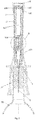
Fig. 1 is a schematic structure diagram of the existing air pressure opener. -
Fig. 2 is a structure diagram of the air pressure opener of the present invention. -
Fig. 3 is an enlarged view of the air pressure relief device of the present invention. -
Fig. 4 is a partially enlarged schematic diagram of the air relief device of the present invention. -
Fig. 5 is a schematic diagram of the air pressure opener of the present invention when it is used and the air is being pumped into the opener. -
Fig. 6 is a partial enlarged view between the top of the inner housing and the outer housing of the air pressure opener of the present invention. - The parts are numbered as: housing 1,
outer housing 11,inner housing 12, inner cavity of thehousing 121, one-way valve 122,piston ring 123,air outlet 124,intake space 13, airpressure relief device 2,venting valve 21,spring 22,seal ring 23,venting hole 24,air needle 3, sleeve of thebottle opener 4,stopper 51,wine bottle 52. - The present invention is further described in detail with reference to the drawings as below. Referring to
Figs. 1-5 , an air pressure opener for opening a grape wine bottle comprises a housing 1 and a pumping device for filling air into a wine bottle. The pumping device comprises aninner cavity 121 of the housing and anair needle 3 with an air channel. Theair needle 3 connects to theinner cavity 121 of the housing, and the air channel in theair needle 3 connects to the inner cavity of thehousing 121. An airpressure relief device 2 is provided in the inner cavity of thehousing 121. When the air pressure in the inner cavity of the housing rises from atmospheric pressure value to a certain value, the airpressure relief device 2 can vent the air in the inner cavity of thehousing 121. The technical effect of this solution is that an airpressure relief device 2 is provided in the air pressure opener. When the bottle is being opened, the pressure in thewine bottle 52 is high. There can be a danger of bottle explosion due to excessive pressure in thewine bottle 52 if thestopper 51 has not been opened and the air is still being pumped in at this time. With the airpressure relief device 2, the airpressure relief device 2 releases the air in thewine bottle 52 in time to prevent the wine bottle from bursting. - As an improvement, the air
pressure relief device 2 comprises aventing valve 21, aspring 22, asealing ring 23, and aventing hole 24. Theventing valve 21 is fixedly installed at the bottom of thespring 22. Preferably, thespring 22 in this solution is a spring with a certain elastic strength to prevent theventing valve 21, which is installed at the bottom of thespring 22, from being easily pushed up by the air pressure in theinner cavity 121 of the housing. Theventing hole 24 is provided at the bottom of the airpressure relief device 2 and asealing ring 23 is provided at the bottom of theventing valve 21. When the air pressure in theinner cavity 121 does not reach to the value which can push theventing valve 21 up, theventing valve 21 and theventing hole 24 are tightly fitted through asealing ring 23 under the elastic force of thespring 22. Theseal ring 23 can prevent the air in theinner cavity 121 from flowing through theventing hole 24 into the atmosphere. When the air pressure in theinner cavity 121 reaches the value which can push up theventing valve 21, thespring 22 is compressed. And then theventing valve 21 is pushed up, with theventing hole 24 being opened, under the air pressure inside theinner cavity 121. The air into theinner cavity 121 is released to the atmosphere by this way. When thewine bottle 52 is being opened, theair needle 3 is inserted into thewine bottle 52. At this time, theinner cavity 121 of the housing is in a state of communicating the air with thewine bottle 52 through theair needle 3. The air pressures in theinner cavity 121 and thewine bottle 52 are the same. A large amount of air can be filled into thewine bottle 52 when the air pumping device is used. When the air pressure in thebottle 52 is high and thestopper 51 is not being pushed out, thewine bottle 52 can be in a risk of bursting due to the excessive pressure inside if the air is still being pushed in thewine bottle 52. In the present invention, the pressure in theinner cavity 121 of the housing is high enough to push up the ventingvalve 21 at this time. Then, the ventingvalve 21 and the ventinghole 24 are opened (seeFig. 4 ). A space is formed and a certain amount of air is vented. The air in theinner cavity 121 follows into the atmosphere through the ventinghole 24 and theair outlet 124. Since the air pressure inside thewine bottle 52 no longer rises at this time being, the danger of thewine bottle 52 bursting is avoided. - A further improvement is that the housing 1 comprises an
outer housing 11 and aninner housing 12, and apiston ring 123 arranged between a top side wall of theinner housing 12 and theouter housing 11. A one-way valve 122 is provided on the top of the inner housing. When the air pressure opener is used, anair intake space 13 is formed between the top of theinner housing 12 and theouter housing 11. Apiston ring 123 is used to control the air flowing into theair intake space 13, and a one-way valve 122 is used to control the direction of the air flowing into thehousing cavity 121 and make the air flow in one direction only. The specific embodiment is as follows: Pulling thehousing 11 upward (seeFig. 5 ) so that the air can enter theintake space 13 through thepiston ring 123, then pressing theouter housing 11 downward (seeFig. 2 ) and thepiston ring 123 is closed. The air in theintake space 13 enters the inner cavity of thehousing 121 through the one-way valve 122. The inner cavity of thehousing 121 connects to and communicates the air with thewine bottle 52 through theair needle 3. By this way, the air is filled into thewine bottle 52 if thehousing 11 repeatedly moves upward or downward (seeFig. 5 andFig. 2 ). If thewine bottle 52 is continuously filled with the air, thestopper 51 is ejected. - A further improvement is that the air
pressure relief device 2 is disposed at a side wall of the inner cavity of thehousing 121. The side wall of theinner housing 12 is provided with anair outlet 124, and the airpressure relief device 2 connects to and communicates the air with theoutlet 124. - A further improvement is that a
sleeve 4 is provided at the bottom of theair pressure opener 4. Theair needle 3 is provided on the sleeve of theair pressure opener 4 and thesleeve 4 is set at the bottle mouth. When the bottle is being opened, theair needle 3 passes through thestopper 51 and into thewine bottle 52. In this case, the sleeve ofbottle opener 4 is set on thewine bottle 52 to make the bottle opening process being more stable. - The embodiment mentioned above only shows part of the implementation manners of the present invention. They should not be understood as a limitation to the scope of the patent of the present invention. It should be noted that the modifications and improvements, which come from the concept of the present invention for the ordinary technicians in this field, fall into the protection scope of the present invention. The protection scope of the invention patent shall be subject to the claims.
Claims (6)
- An air pressure opener for opening a grape wine bottle, comprising a housing and an air pumping device for filling air into the wine bottle, the air pumping device comprises an inner cavity of a housing and an air needle with an air channel inside; the air needle connects to the inner cavity of the housing; the air channel in the air needle connects to the inner cavity of the housing, characterized in that an air pressure relief device is provided in the inner cavity of the housing, and when the value of air pressure in the inner cavity of the housing rises from atmospheric pressure to a certain value, the air pressure relief device can release the air pressure in the inner cavity of the housing.
- The air pressure opener for opening grape wine bottle according to claim 1, characterized in that the air pressure relief device comprises a venting valve, a spring, a sealing ring and a venting hole, the venting valve being fixedly installed at the bottom of the spring, and the venting hole being provided at the bottom of the air pressure relief device, a sealing ring is also provided at the bottom of the venting valve; when the air pressure value of the inner cavity of the housing does not reach a value capable of ejecting the venting valve, the venting valve tightly fits the venting hole through the sealing ring under the action of the spring force; when the air pressure value of the inner cavity of the housing reaches a value capable of ejecting the venting valve, the spring will be compressed and the venting valve and the venting hole will be opened under the air pressure of the inner cavity of the housing, by this way, the air pressure in the inner cavity of the housing is released.
- The air pressure opener for opening grape wine bottle according to claim 2, characterized in that the housing comprises an outer housing and an inner housing, and a piston ring is arranged between the top side wall of the inner housing and the outer housing, and a one-way valve is provided on the top of the inner housing.
- The air pressure opener for opening grape wine bottle according to claim 3, characterized in that when the bottle opener works, an air intake space is formed between the top of the inner housing and the outer housing, and the piston ring controls the air flowing into the air intake space, and the one-way valve controls the air flowing into the inner cavity of the housing in one direction.
- The air pressure opener for opening grape wine bottle according to claim 4, characterized in that the air pressure relief device is disposed on the side wall of the inner cavity of the housing, the inner side wall of the housing is provided with an air outlet, and the air pressure relief device communicates the air to the atmosphere though the outlet.
- The air pressure opener for opening grape wine bottle according to claim 5, characterized in that a sleeve of bottle opener is provided at the bottom of the bottle opener, and the air needle is accommodated in the sleeve of bottle opener; when the grape wine bottle is being opened, the bottle opener is set on the bottle mouth, and the air needle is inserted into the grape wine bottle through the bottle stopper.
Applications Claiming Priority (2)
| Application Number | Priority Date | Filing Date | Title |
|---|---|---|---|
| CN201921768985 | 2019-10-21 | ||
| PCT/CN2020/080059 WO2021077666A1 (en) | 2019-10-21 | 2020-03-18 | Pneumatic bottle opener for wine bottle |
Publications (4)
| Publication Number | Publication Date |
|---|---|
| EP3831768A1 true EP3831768A1 (en) | 2021-06-09 |
| EP3831768A4 EP3831768A4 (en) | 2021-11-10 |
| EP3831768B1 EP3831768B1 (en) | 2026-01-07 |
| EP3831768C0 EP3831768C0 (en) | 2026-01-07 |
Family
ID=73179868
Family Applications (1)
| Application Number | Title | Priority Date | Filing Date |
|---|---|---|---|
| EP20804422.2A Active EP3831768B1 (en) | 2019-10-21 | 2020-03-18 | Pneumatic bottle opener for wine bottle |
Country Status (4)
| Country | Link |
|---|---|
| US (1) | US12037232B2 (en) |
| EP (1) | EP3831768B1 (en) |
| CN (2) | CN211946203U (en) |
| WO (1) | WO2021077666A1 (en) |
Cited By (1)
| Publication number | Priority date | Publication date | Assignee | Title |
|---|---|---|---|---|
| CN112758871A (en) * | 2019-10-21 | 2021-05-07 | 郑羽彤 | Air pressure bottle opener for wine bottle |
Families Citing this family (1)
| Publication number | Priority date | Publication date | Assignee | Title |
|---|---|---|---|---|
| CN114380258A (en) * | 2022-02-16 | 2022-04-22 | 宁夏回族自治区农业学校 | Bottled wine batch processing quick uncork device |
Family Cites Families (15)
| Publication number | Priority date | Publication date | Assignee | Title |
|---|---|---|---|---|
| JPS5983799A (en) * | 1982-11-02 | 1984-05-15 | Nippon Steel Corp | Method and apparatus for metal plating |
| JPS5983799U (en) * | 1983-08-29 | 1984-06-06 | 株式会社研進 | corkscrew |
| US5005446A (en) * | 1987-01-13 | 1991-04-09 | Mackey Edward R | Pressurized cork-removal apparatus for wine bottles and other containers |
| US5012703A (en) * | 1990-02-05 | 1991-05-07 | Helmut Reinbacher | Cork removal apparatus |
| US20050076741A1 (en) * | 2003-10-09 | 2005-04-14 | C. C. & L Company Limited | Cork removing device |
| DE202004004558U1 (en) * | 2004-03-23 | 2004-05-27 | Holo Electronics Co., Ltd. | Ball pump type bottle opener for opening bottles has ball pump type air pump, grip bush for bottle neck and intermediate bush fitting telescopically in grip bush |
| CN1751982A (en) * | 2004-09-24 | 2006-03-29 | 思力图有限公司 | cork removing device |
| US7231850B2 (en) * | 2005-11-08 | 2007-06-19 | Ching-Chen Wang | Manual wine bottle opener |
| CN2887832Y (en) * | 2006-02-28 | 2007-04-11 | 梁国和 | Pneumatic opener |
| TWI348455B (en) * | 2009-04-21 | 2011-09-11 | Ho Tien Chen | Cork stopper remover |
| CN201647960U (en) * | 2010-01-08 | 2010-11-24 | 林顺安 | Bottle opener |
| CN101759127A (en) * | 2010-01-08 | 2010-06-30 | 林顺安 | Bottle opener |
| CN202164090U (en) * | 2011-06-23 | 2012-03-14 | 东莞精博电子科技有限公司 | Multifunctional air pressure type bottle opener |
| US9446936B2 (en) * | 2014-04-25 | 2016-09-20 | Wei-Tung Kao | Pneumatically operated opener device |
| WO2021077666A1 (en) * | 2019-10-21 | 2021-04-29 | 郑羽彤 | Pneumatic bottle opener for wine bottle |
-
2020
- 2020-03-18 WO PCT/CN2020/080059 patent/WO2021077666A1/en not_active Ceased
- 2020-03-18 CN CN202020348121.6U patent/CN211946203U/en active Active
- 2020-03-18 CN CN202010193484.1A patent/CN112758871A/en active Pending
- 2020-03-18 EP EP20804422.2A patent/EP3831768B1/en active Active
- 2020-03-18 US US17/042,674 patent/US12037232B2/en active Active
Cited By (1)
| Publication number | Priority date | Publication date | Assignee | Title |
|---|---|---|---|---|
| CN112758871A (en) * | 2019-10-21 | 2021-05-07 | 郑羽彤 | Air pressure bottle opener for wine bottle |
Also Published As
| Publication number | Publication date |
|---|---|
| EP3831768A4 (en) | 2021-11-10 |
| EP3831768B1 (en) | 2026-01-07 |
| US20230113838A1 (en) | 2023-04-13 |
| WO2021077666A1 (en) | 2021-04-29 |
| EP3831768C0 (en) | 2026-01-07 |
| CN112758871A (en) | 2021-05-07 |
| US12037232B2 (en) | 2024-07-16 |
| CN211946203U (en) | 2020-11-17 |
Similar Documents
| Publication | Publication Date | Title |
|---|---|---|
| US12037232B2 (en) | Air pressure opener for opening wine bottle | |
| US6530401B1 (en) | Method for the preservation of an opened drink bottle | |
| US11117148B2 (en) | Pump assembly and container with contents discharge function | |
| CN207830707U (en) | A kind of vacuum pumping valve | |
| CN111075968B (en) | Safe pressure tank | |
| US4791834A (en) | Pressure metering cork extractor | |
| CN110002095A (en) | Novel inflating cover | |
| CN215400017U (en) | Vacuum storage tank | |
| CN208007704U (en) | A kind of vacuum tank | |
| CN214946629U (en) | Gas cylinder valve with pressure maintaining function | |
| CN201501608U (en) | Automatic-feeding vacuum tea caddy | |
| CN118025654A (en) | A gas cylinder sealed container with an improved plug cover gas outlet structure | |
| CN213849982U (en) | Juice glass and juice extractor | |
| CN212356508U (en) | Liquid pumping device | |
| US11420817B2 (en) | Pressure vacuum vent | |
| CN210770512U (en) | Piston type selector valve | |
| CN219088914U (en) | Pressure indication stop valve | |
| CN219567561U (en) | Wine taking device | |
| CN207670966U (en) | A kind of vacuum plant | |
| CN209018536U (en) | A kind of oil bottle | |
| CN209177216U (en) | a foam pump | |
| CN209506519U (en) | A kind of wine lance of band manually and automatically pressure relief valve | |
| CN220891198U (en) | Driving bottle container valve | |
| CN221478140U (en) | Packaging bag and exhaust valve thereof | |
| CN205819924U (en) | sealing column core |
Legal Events
| Date | Code | Title | Description |
|---|---|---|---|
| STAA | Information on the status of an ep patent application or granted ep patent |
Free format text: STATUS: UNKNOWN |
|
| STAA | Information on the status of an ep patent application or granted ep patent |
Free format text: STATUS: THE INTERNATIONAL PUBLICATION HAS BEEN MADE |
|
| PUAI | Public reference made under article 153(3) epc to a published international application that has entered the european phase |
Free format text: ORIGINAL CODE: 0009012 |
|
| STAA | Information on the status of an ep patent application or granted ep patent |
Free format text: STATUS: REQUEST FOR EXAMINATION WAS MADE |
|
| 17P | Request for examination filed |
Effective date: 20201120 |
|
| AK | Designated contracting states |
Kind code of ref document: A1 Designated state(s): AL AT BE BG CH CY CZ DE DK EE ES FI FR GB GR HR HU IE IS IT LI LT LU LV MC MK MT NL NO PL PT RO RS SE SI SK SM TR |
|
| A4 | Supplementary search report drawn up and despatched |
Effective date: 20211012 |
|
| RIC1 | Information provided on ipc code assigned before grant |
Ipc: B67B 7/08 20060101AFI20211006BHEP |
|
| DAV | Request for validation of the european patent (deleted) | ||
| DAX | Request for extension of the european patent (deleted) | ||
| STAA | Information on the status of an ep patent application or granted ep patent |
Free format text: STATUS: EXAMINATION IS IN PROGRESS |
|
| 17Q | First examination report despatched |
Effective date: 20231205 |
|
| GRAP | Despatch of communication of intention to grant a patent |
Free format text: ORIGINAL CODE: EPIDOSNIGR1 |
|
| STAA | Information on the status of an ep patent application or granted ep patent |
Free format text: STATUS: GRANT OF PATENT IS INTENDED |
|
| INTG | Intention to grant announced |
Effective date: 20250806 |
|
| GRAS | Grant fee paid |
Free format text: ORIGINAL CODE: EPIDOSNIGR3 |
|
| GRAA | (expected) grant |
Free format text: ORIGINAL CODE: 0009210 |
|
| STAA | Information on the status of an ep patent application or granted ep patent |
Free format text: STATUS: THE PATENT HAS BEEN GRANTED |
|
| AK | Designated contracting states |
Kind code of ref document: B1 Designated state(s): AL AT BE BG CH CY CZ DE DK EE ES FI FR GB GR HR HU IE IS IT LI LT LU LV MC MK MT NL NO PL PT RO RS SE SI SK SM TR |
|
| REG | Reference to a national code |
Ref country code: CH Ref legal event code: F10 Free format text: ST27 STATUS EVENT CODE: U-0-0-F10-F00 (AS PROVIDED BY THE NATIONAL OFFICE) Effective date: 20260107 Ref country code: GB Ref legal event code: FG4D |
|
| REG | Reference to a national code |
Ref country code: DE Ref legal event code: R096 Ref document number: 602020065233 Country of ref document: DE |
|
| REG | Reference to a national code |
Ref country code: IE Ref legal event code: FG4D |
|
| U01 | Request for unitary effect filed |
Effective date: 20260209 |
|
| U07 | Unitary effect registered |
Designated state(s): AT BE BG DE DK EE FI FR IT LT LU LV MT NL PT RO SE SI Effective date: 20260312 |
|
| U20 | Renewal fee for the european patent with unitary effect paid |
Year of fee payment: 7 Effective date: 20260330 |
|
| PG25 | Lapsed in a contracting state [announced via postgrant information from national office to epo] |
Ref country code: RS Free format text: LAPSE BECAUSE OF FAILURE TO SUBMIT A TRANSLATION OF THE DESCRIPTION OR TO PAY THE FEE WITHIN THE PRESCRIBED TIME-LIMIT Effective date: 20260407 |
|
| PG25 | Lapsed in a contracting state [announced via postgrant information from national office to epo] |
Ref country code: ES Free format text: LAPSE BECAUSE OF FAILURE TO SUBMIT A TRANSLATION OF THE DESCRIPTION OR TO PAY THE FEE WITHIN THE PRESCRIBED TIME-LIMIT Effective date: 20260107 |
|
| PG25 | Lapsed in a contracting state [announced via postgrant information from national office to epo] |
Ref country code: PL Free format text: LAPSE BECAUSE OF FAILURE TO SUBMIT A TRANSLATION OF THE DESCRIPTION OR TO PAY THE FEE WITHIN THE PRESCRIBED TIME-LIMIT Effective date: 20260107 |
|
| PG25 | Lapsed in a contracting state [announced via postgrant information from national office to epo] |
Ref country code: GR Free format text: LAPSE BECAUSE OF FAILURE TO SUBMIT A TRANSLATION OF THE DESCRIPTION OR TO PAY THE FEE WITHIN THE PRESCRIBED TIME-LIMIT Effective date: 20260408 |
|
| PG25 | Lapsed in a contracting state [announced via postgrant information from national office to epo] |
Ref country code: NO Free format text: LAPSE BECAUSE OF FAILURE TO SUBMIT A TRANSLATION OF THE DESCRIPTION OR TO PAY THE FEE WITHIN THE PRESCRIBED TIME-LIMIT Effective date: 20260407 |
|
| PG25 | Lapsed in a contracting state [announced via postgrant information from national office to epo] |
Ref country code: HR Free format text: LAPSE BECAUSE OF FAILURE TO SUBMIT A TRANSLATION OF THE DESCRIPTION OR TO PAY THE FEE WITHIN THE PRESCRIBED TIME-LIMIT Effective date: 20260107 |
|
| PG25 | Lapsed in a contracting state [announced via postgrant information from national office to epo] |
Ref country code: IS Free format text: LAPSE BECAUSE OF FAILURE TO SUBMIT A TRANSLATION OF THE DESCRIPTION OR TO PAY THE FEE WITHIN THE PRESCRIBED TIME-LIMIT Effective date: 20260507 |