EP3831714A1 - Unmanned aerial vehicle and associated method for reducing drag during flight of an unmanned aerial vehicle - Google Patents
Unmanned aerial vehicle and associated method for reducing drag during flight of an unmanned aerial vehicle Download PDFInfo
- Publication number
- EP3831714A1 EP3831714A1 EP20208141.0A EP20208141A EP3831714A1 EP 3831714 A1 EP3831714 A1 EP 3831714A1 EP 20208141 A EP20208141 A EP 20208141A EP 3831714 A1 EP3831714 A1 EP 3831714A1
- Authority
- EP
- European Patent Office
- Prior art keywords
- frame
- boom
- end portion
- unmanned aerial
- aerial vehicle
- Prior art date
- Legal status (The legal status is an assumption and is not a legal conclusion. Google has not performed a legal analysis and makes no representation as to the accuracy of the status listed.)
- Granted
Links
Images






Classifications
-
- B—PERFORMING OPERATIONS; TRANSPORTING
- B64—AIRCRAFT; AVIATION; COSMONAUTICS
- B64C—AEROPLANES; HELICOPTERS
- B64C7/00—Structures or fairings not otherwise provided for
-
- B—PERFORMING OPERATIONS; TRANSPORTING
- B64—AIRCRAFT; AVIATION; COSMONAUTICS
- B64U—UNMANNED AERIAL VEHICLES [UAV]; EQUIPMENT THEREFOR
- B64U10/00—Type of UAV
- B64U10/10—Rotorcrafts
- B64U10/13—Flying platforms
- B64U10/16—Flying platforms with five or more distinct rotor axes, e.g. octocopters
-
- B—PERFORMING OPERATIONS; TRANSPORTING
- B64—AIRCRAFT; AVIATION; COSMONAUTICS
- B64U—UNMANNED AERIAL VEHICLES [UAV]; EQUIPMENT THEREFOR
- B64U20/00—Constructional aspects of UAVs
- B64U20/70—Constructional aspects of the UAV body
-
- B—PERFORMING OPERATIONS; TRANSPORTING
- B64—AIRCRAFT; AVIATION; COSMONAUTICS
- B64U—UNMANNED AERIAL VEHICLES [UAV]; EQUIPMENT THEREFOR
- B64U30/00—Means for producing lift; Empennages; Arrangements thereof
- B64U30/20—Rotors; Rotor supports
-
- B—PERFORMING OPERATIONS; TRANSPORTING
- B64—AIRCRAFT; AVIATION; COSMONAUTICS
- B64U—UNMANNED AERIAL VEHICLES [UAV]; EQUIPMENT THEREFOR
- B64U2101/00—UAVs specially adapted for particular uses or applications
-
- B—PERFORMING OPERATIONS; TRANSPORTING
- B64—AIRCRAFT; AVIATION; COSMONAUTICS
- B64U—UNMANNED AERIAL VEHICLES [UAV]; EQUIPMENT THEREFOR
- B64U60/00—Undercarriages
- B64U60/50—Undercarriages with landing legs
Definitions
- This application relates to unmanned aerial vehicles and, more particularly, to the use of fairings to reduce drag during flight of unmanned aerial vehicles.
- Unmanned aerial vehicles are increasingly used for performing a variety of functions in civilian, commercial, and military applications.
- UAVs may be implemented for delivering payloads, performing emergency services such as firefighting management, locating schools of fish, and other functions.
- Unmanned aerial vehicles are typically powered by one or more batteries. Therefore, unmanned aerial vehicles remain in service for only a limited amounted of time (i.e., the service duration), as dictated by battery life. Once a battery on an unmanned aerial vehicle is exhausted, the unmanned aerial vehicle must be taken out of service while the exhausted battery is charged or while the exhausted battery is swapped with a charged battery.
- Drag the greater the drag, the more energy is consumed by the unmanned aerial vehicle per a given flight path, and the shorter the service duration.
- the disclosed unmanned aerial vehicle includes a frame elongated along a frame axis, the frame has a leading side and an aft side, the frame further includes a left end portion and a right end portion, a first forward rotor assembly connected to the left end portion of the frame, a second forward rotor assembly connected to the right end portion of the frame, the first forward rotor assembly and the second forward rotor assembly being positioned on the leading side of the frame, a compartment connected to the frame, the compartment having a leading side, and a curved leading-edge fairing disposed on the frame, wherein a portion of the curved leading-edge fairing extends to cover the leading side of the compartment, and wherein the curved leading-edge fairing reduces drag during flight in a forward direction to enable a substantially level flight profile.
- the disclosed unmanned aerial vehicle includes a frame elongated along a frame axis, the frame having a leading side and an aft side, the frame further including a left end portion and a right end portion axially opposed from the left end portion relative to the frame axis, a first forward rotor assembly connected to the left end portion of the frame by way of a first forward boom, a first aft rotor assembly connected to the left end portion of the frame by way of a first aft boom, a first outboard rotor assembly connected to the left end portion of the frame by way of a first outboard boom, the first outboard boom having a leading side and an aft side, a first forward boom fairing positioned over the leading side of the first outboard boom, a second forward rotor assembly connected to the right end portion of the frame by way of a second forward boom, a second aft rotor assembly connected to the right end portion of the frame by way of a second aft boom,
- the unmanned aerial vehicle includes a frame elongated along a frame axis, the frame having a leading side and an aft side, as well as a left end portion and a right end portion, at least two rotor assemblies connected to the left end portion of the frame by way of at least two first booms, and at least two rotor assemblies connected to the right end portion of the frame by way of at least two second booms.
- the disclosed method for reducing drag during flight of such unmanned aerial vehicle includes steps of (1) positioning a curved leading-edge fairing over at least a portion of the leading side of the frame; (2) positioning a first forward boom fairing over a boom of the at least two first booms; and (3) positioning a second forward boom fairing over a boom of the at least two second booms.
- the disclosed unmanned aerial vehicles may have a pitch angle about the frame axis of less than 13 degrees (e.g., about 10 degrees or less) when traveling in a forward direction at airspeeds up to about 50 knots.
- the disclosed unmanned aerial vehicles may experience significantly less drag, thereby significantly increasing service duration of the unmanned aerial vehicles.
- one example of the disclosed unmanned aerial vehicle includes a frame 12, a first forward rotor assembly 30, a second forward rotor assembly 40, a first aft rotor assembly 50, a second aft rotor assembly 60, a first outboard rotor assembly 70, a second outboard rotor assembly 80, a compartment 90, a curved leading-edge fairing 100, a first forward boom fairing 120 and a second forward boom fairing 150.
- the unmanned aerial vehicle 10 may further include a first aft boom fairing 130 and a second aft boom fairing 160.
- the unmanned aerial vehicle 10 includes a pair of forward rotor assemblies 30, 40, a pair of aft rotor assemblies 50, 60, a pair of outboard rotor assemblies 70, 80, and a pair of forward boom fairings 120, 150, and a pair of aft boom fairings 130, 160.
- Various additional components and features may be included in the disclosed unmanned aerial vehicle 10 without departing from the scope of the present disclosure.
- the frame 12 of the disclosed unmanned aerial vehicle 10 may include a truss 22 (e.g., a Brown-type truss) and may be elongated along a frame axis A F , which may be orthogonal to (e.g., lateral relative to) the forward direction F the unmanned aerial vehicle 10. Therefore, the frame 12 may have a left end portion 18 and a right end portion 20 that is axially opposed from the left end portion 18 relative to the frame axis A F .
- the frame 12 may further have a leading side 14 and an aft side 16, as well as an underside 24 and a topside 26.
- the first forward rotor assembly 30 of the disclosed unmanned aerial vehicle 10 is connected to the left end portion 18 of the frame 12 on the leading side 14 of the frame 12.
- the unmanned aerial vehicle 10 may include a first forward boom 32 having a proximal end portion 31 ( Fig. 4 ) connected to the left end portion 18 of the frame 12 and a distal end portion 33 ( Fig. 4 ) connected to the first forward rotor assembly 30.
- the first forward rotor assembly 30 may include a rotor shaft 34, a rotor 36, and a motor 38, as best shown in Figs. 1-3 .
- the rotor shaft 34 may define a rotor shaft axis A R1 , which may be slightly tilted inward (i.e., toward the right end portion 20 of the frame 12) and slightly tilted in the forward direction F.
- the rotor shaft 34 may be rotatable about the rotor shaft A R1 .
- the rotor 36 may be fixedly connected to the rotor shaft 34 such that the rotor 36 rotates with the rotor shaft 34.
- the motor 38 (e.g., a battery-powered electric motor) may be operatively connected to the rotor shaft 34 to cause the rotor shaft 34 and, thus, the rotor 36, to rotate about the rotor shaft axis A R1 .
- the first forward rotor assembly 30 may include a pair or rotors 36, 37 (e.g., a pair of co-rotating rotors (same direction)).
- the second rotor 37 of the first forward rotor assembly 30 may be fixedly connected to a second rotor shaft 35 and may be powered by a second motor 39.
- the motors 38, 39 of the first forward rotor assembly 30 may be configured as a coaxial motor stack.
- the second forward rotor assembly 40 of the disclosed unmanned aerial vehicle 10 may be connected to the right end portion 20 of the frame 12 on the leading side 14 of the frame 12.
- the unmanned aerial vehicle 10 may include a second forward boom 42 having a proximal end portion 41 ( Fig. 4 ) connected to the right end portion 20 of the frame 12 and a distal end portion 43 ( Fig. 4 ) connected to the second forward rotor assembly 40. Therefore, the unmanned aerial vehicle 10 may have a pair of forward booms 32, 42.
- the second forward rotor assembly 40 may include a rotor shaft 44, a rotor 46, and a motor 48.
- the rotor shaft 44 may define a rotor shaft axis A R2 , which may be slightly tilted inward (i.e., toward the left end portion 18 of the frame 12) and slightly tilted in the forward direction F.
- the rotor shaft 44 may be rotatable about the rotor shaft A R2 .
- the rotor 46 may be fixedly connected to the rotor shaft 44 such that the rotor 46 rotates with the rotor shaft 44.
- the motor 48 (e.g., a battery-powered electric motor) may be operatively connected to the rotor shaft 44 to cause the rotor shaft 44 and, thus, the rotor 46, to rotate about the rotor shaft axis A R2 .
- the second forward rotor assembly 40 may include a pair or rotors 46, 47 (e.g., a pair of co-rotating rotors (same direction)).
- the second rotor 47 of the second forward rotor assembly 40 may be fixedly connected to a second rotor shaft 45 and may be powered by a second motor 49.
- the motors 48, 49 of the second forward rotor assembly 40 may be configured as a coaxial motor stack.
- the first aft rotor assembly 50 of the disclosed unmanned aerial vehicle 10 may be connected to the left end portion 18 of the frame 12 on the aft side 16 of the frame 12.
- the unmanned aerial vehicle 10 may include a first aft boom 52 having a proximal end portion 51 ( Fig. 4 ) connected to the left end portion 18 of the frame 12 and a distal end portion 53 ( Fig. 4 ) connected to the first aft rotor assembly 50.
- the first aft rotor assembly 50 may include a rotor shaft 54, a rotor 56, and a motor 58.
- the rotor shaft 54 may define a rotor shaft axis A R3 , which may be slightly tilted inward (i.e., toward the right end portion 20 of the frame 12).
- the rotor shaft 54 may be rotatable about the rotor shaft A R3 .
- the rotor 56 may be fixedly connected to the rotor shaft 54 such that the rotor 56 rotates with the rotor shaft 54.
- the motor 58 (e.g., a battery-powered electric motor) may be operatively connected to the rotor shaft 54 to cause the rotor shaft 54 and, thus, the rotor 56, to rotate about the rotor shaft axis A R3 .
- the first aft rotor assembly 50 may include a pair or rotors 56, 57 (e.g., a pair of co-rotating rotors (same direction)).
- the second rotor 57 of the first aft rotor assembly 50 may be fixedly connected to a second rotor shaft 55 and may be powered by a second motor 59.
- the motors 58, 59 of the first aft rotor assembly 50 may be configured as a coaxial motor stack.
- the second aft rotor assembly 60 of the disclosed unmanned aerial vehicle 10 may be connected to the right end portion 20 of the frame 12 on the aft side 16 of the frame 12.
- the unmanned aerial vehicle 10 may include a second aft boom 62 having a proximal end portion 61 ( Fig. 4 ) connected to the right end portion 20 of the frame 12 and a distal end portion 63 ( Fig. 4 ) connected to the second aft rotor assembly 60. Therefore, the unmanned aerial vehicle 10 may have a pair of aft booms 52, 62.
- the second aft rotor assembly 60 may include a rotor shaft 64, a rotor 66, and a motor 68.
- the rotor shaft 64 may define a rotor shaft axis A R4 , which may be slightly tilted inward (i.e., toward the left end portion 18 of the frame 12).
- the rotor shaft 64 may be rotatable about the rotor shaft A R4 .
- the rotor 66 may be fixedly connected to the rotor shaft 64 such that the rotor 66 rotates with the rotor shaft 64.
- the motor 68 (e.g., a battery-powered electric motor) may be operatively connected to the rotor shaft 64 to cause the rotor shaft 64 and, thus, the rotor 66, to rotate about the rotor shaft axis A R4 .
- the second aft rotor assembly 60 may include a pair or rotors 66, 67 (e.g., a pair of co-rotating rotors (same direction)).
- the second rotor 67 of the second aft rotor assembly 60 may be fixedly connected to a second rotor shaft 65 and may be powered by a second motor 69.
- the motors 68, 69 of the second aft rotor assembly 60 may be configured as a coaxial motor stack.
- the first outboard rotor assembly 70 of the disclosed unmanned aerial vehicle 10 may be connected to the left end portion 18 of the frame 12 and may protrude laterally outward from the frame 12 (e.g., along the frame axis A F ).
- the unmanned aerial vehicle 10 may include a first outboard boom 72 having a leading side 110 and an aft side 112, as well as a proximal end portion 114 and a distal end portion 116 opposed from the proximal end portion 114.
- the proximal end portion 114 of the first outboard boom 72 may be connected to the left end portion 18 of the frame 12 and the distal end portion 116 of the first outboard boom 72 may be connected to the first outboard rotor assembly 70.
- the first outboard rotor assembly 70 may include a rotor shaft 74, a rotor 76, and a motor 78.
- the rotor shaft 74 may define a rotor shaft axis A R5 , which may be slightly tilted in the forward direction F.
- the rotor shaft 74 may be rotatable about the rotor shaft A R5 .
- the rotor 76 may be fixedly connected to the rotor shaft 74 such that the rotor 76 rotates with the rotor shaft 74.
- the motor 78 (e.g., a battery-powered electric motor) may be operatively connected to the rotor shaft 74 to cause the rotor shaft 74 and, thus, the rotor 76, to rotate about the rotor shaft axis A R5 .
- the first outboard rotor assembly 70 may include a pair or rotors 76, 77 (e.g., a pair of contra-rotating rotors).
- the second rotor 77 of the first outboard rotor assembly 70 may be fixedly connected to a second rotor shaft 75 and may be powered by a second motor 79.
- the motors 78, 79 of the first outboard rotor assembly 70 may be configured as a coaxial motor stack.
- the second outboard rotor assembly 80 of the disclosed unmanned aerial vehicle 10 may be connected to the right end portion 20 of the frame 12 and may protrude laterally outward from the frame 12 (e.g., along the frame axis A F ).
- the unmanned aerial vehicle 10 may include a second outboard boom 82 having a leading side 140 and an aft side 142, as well as a proximal end portion 144 and a distal end portion 146 opposed from the proximal end portion 144.
- the proximal end portion 144 of the second outboard boom 82 may be connected to the right end portion 20 of the frame 12 and the distal end portion 146 of the second outboard boom 82 may be connected to the second outboard rotor assembly 80. Therefore, the unmanned aerial vehicle 10 may have a pair of outboard booms 72, 82.
- the second outboard rotor assembly 80 may include a rotor shaft 84, a rotor 86, and a motor 88.
- the rotor shaft 84 may define a rotor shaft axis A R6 , which may be slightly tilted in the forward direction F.
- the rotor shaft 84 may be rotatable about the rotor shaft A R6 .
- the rotor 86 may be fixedly connected to the rotor shaft 84 such that the rotor 86 rotates with the rotor shaft 84.
- the motor 88 (e.g., a battery-powered electric motor) may be operatively connected to the rotor shaft 84 to cause the rotor shaft 84 and, thus, the rotor 86, to rotate about the rotor shaft axis A R6 .
- the second outboard rotor assembly 80 may include a pair or rotors 86, 87 (e.g., a pair of contra-rotating rotors).
- the second rotor 87 of the second outboard rotor assembly 80 may be fixedly connected to a second rotor shaft 85 and may be powered by a second motor 89.
- the motors 88, 89 of the second outboard rotor assembly 80 may be configured as a coaxial motor stack.
- the compartment 90 of the disclosed unmanned aerial vehicle 10 has a leading side 92 and an aft side opposed from the leading side 92, and is connected to the frame 12.
- the compartment 90 may be connected to the underside 24 of the frame 12, as shown in Figs. 5 and 6 .
- the compartment 90 may be connected to the topside 26 of the frame 12.
- the compartment 90 may define a partially enclosed or a fully enclosed space for storing various items on the unmanned aerial vehicle 10.
- the compartment 90 may be a battery compartment, and a battery 94 may be received (e.g., housed) in the compartment 90.
- the battery 94 may be used to power the various motors 38, 39, 48, 49, 58, 59, 68, 69, 78, 79, 88, 89 of the unmanned aerial vehicle 10.
- the compartment 90 may be a payload compartment.
- the compartment 90 may be configured for receiving both a battery 94 and a payload (not shown).
- the unmanned aerial vehicle 10 may further include landing gear 96.
- the landing gear 96 may be connected to the frame 12, such as to the underside 24 of the frame 12. With the landing gear 96 positioned on the underside 24 of the frame 12, the landing gear 96 may elevate the frame 12 above any structure (e.g., landing pad (not shown)) upon which the unmanned aerial vehicle 10 is resting.
- the curved leading-edge fairing 100 of the disclosed unmanned aerial vehicle 10 is positioned over at least a portion of the leading side 14 of the frame 12 and at least a portion of the leading side 92 of the compartment 90.
- the curved leading-edge fairing 100 substantially completely covers (e.g., covers at least 90 percent of) the leading side 14 of the frame 12 and the leading side 92 of the compartment 90.
- the curved leading-edge fairing 100 may be disposed relative to the frame 12 such that a first portion 101 of the curved leading-edge fairing 100 extends over the leading side 14 of the frame 12 and a second portion 103 extends over the leading side 92 of the compartment 90.
- the curved leading-edge fairing 100 may include an upper edge 102, a lower edge 104A associated with the first portion 101 of the curved leading-edge fairing 100, and a lower edge 104B associated with the second portion 103 of the curved leading-edge fairing 100, and may have a continuous curvature 106 from the upper edge 102 to the lower edge 104A and a continuous curvature 106 from the upper edge 102 to the lower edge 104B.
- the curved leading-edge fairing 100 has a minimum radius of curvature of at least about 7,62 cm (i.e. about 3 inches).
- the curved leading-edge fairing 100 may have an aerodynamic shape that reduces drag during flight of the unmanned aerial vehicle 10 in a forward direction F ( Fig. 1 ) to enable a substantially level flight profile.
- the substantially level flight profile is a pitch angle ⁇ of the frame 12 about the frame axis A F , during flight in a forward direction F, of 0 degrees up to about 13 degrees, and more preferably a pitch angle ⁇ of 0 to about 10 degrees.
- the curved leading-edge fairing 100 may be constructed from various materials without departing from the scope of the present disclosure. Appropriate material selection may ensure that the outer surface 108 of the curved leading-edge fairing 100 is sufficiently smooth and aerodynamic.
- suitable materials include, without limitation, metals and metal alloys (e.g., titanium alloys), polymeric materials, and composite materials (e.g., carbon fiber-reinforced epoxy composites).
- the first forward boom fairing 120 of the disclosed unmanned aerial vehicle 10 is positioned over at least a portion of the leading side 110 of the first outboard boom 72. In one particular construction, the first forward boom fairing 120 substantially completely covers the leading side 110 of the first outboard boom 72.
- the first forward boom fairing 120 may include an upper edge 122 and a lower edge 124, and may have a continuous curvature 126 from the upper edge 122 to the lower edge 124.
- the first forward boom fairing 120 may have a first radius of curvature R L1 proximate (i.e., at or near) the proximal end portion 114 ( Fig. 6 ) of the first outboard boom 72 and a second radius of curvature R L2 proximate the distal end portion 116 ( Fig.
- the first radius of curvature R L1 is substantially greater (e.g., at least 20 percent greater, such as at least 50 percent greater) than the second radius of curvature R L2 .
- the first radius of curvature R L1 may be about 14,61 cm (i.e. about 5.75 inches) and the second radius of curvature R L2 may be about 7,62 cm (i.e. about 3 inches). Therefore, the first forward boom fairing 120 may have an aerodynamic shape that reduces drag during flight of the unmanned aerial vehicle 10 in a forward direction F ( Fig. 1 ) to enable a substantially level flight profile.
- the second forward boom fairing 150 of the disclosed unmanned aerial vehicle 10 is positioned over at least a portion of the leading side 110 of the second outboard boom 82. In one particular construction, the second forward boom fairing 150 substantially completely covers the leading side 140 of the second outboard boom 82.
- the second forward boom fairing 150 may include an upper edge 152 and a lower edge 154, and may have a continuous curvature 156 from the upper edge 152 to the lower edge 154.
- the second forward boom fairing 150 may have a first radius of curvature R R1 proximate (i.e., at or near) the proximal end portion 144 ( Fig. 6 ) of the second forward boom fairing 150 and a second radius of curvature R R2 proximate the distal end portion 146 ( Fig.
- the second forward boom fairing 150 may have an aerodynamic shape that reduces drag during flight of the unmanned aerial vehicle 10 in a forward direction F ( Fig. 1 ) to enable a substantially level flight profile.
- the first aft boom fairing 130 of the disclosed unmanned aerial vehicle 10 is positioned over at least a portion of the aft side 112 of the first outboard boom 72.
- the first aft boom fairing 130 may be sized, shaped and configured in a manner similar to the first forward boom fairing 120 on the forward side 110 of the first outboard boom 72.
- the second aft boom fairing 160 of the disclosed unmanned aerial vehicle 10 is positioned over at least a portion of the aft side 142 of the second outboard boom 82.
- the second aft boom fairing 160 may be sized, shaped and configured in a manner similar to the second forward boom fairing 150 on the forward side 140 of the second outboard boom 82.
- the first aft boom fairing 130 and the second aft boom fairing 160 may facilitate drag reduction. Additionally, the first aft boom fairing 130 and the second aft boom fairing 160 may enhance handling qualities in hover.
- the first forward boom fairing 120 and the second forward boom fairing 150 may be identical to but opposite of the first aft boom fairing 130 and the second aft boom fairing 160. Therefore, in hover, the first forward boom fairing 120, the second forward boom fairing 150, the first aft boom fairing 130, and the second aft boom fairing 160 may passively have equal and opposite forces in the horizontal direction, helping the flight control system to hold position above a point on the ground.
- the presence on the unmanned aerial vehicle 10 of the curved leading-edge fairing 100, the first forward boom fairing 120, the second forward boom fairing 150, the first aft boom fairing 130, and/or the second aft boom fairing 160 may significantly reduce drag when the unmanned aerial vehicle 10 moves in a forward direction F, thereby reducing power consumption (e.g., up to about 20 percent) and increasing service duration of the unmanned aerial vehicle 10. Therefore, the pitch angle ⁇ (i.e., the angle between the forward direction F and the pitch attitude P of the frame 12 about the frame axis A F ) of the unmanned aerial vehicle 10 during flight in the forward direction F can be significantly reduced (e.g., a predetermined reduction in pitch angle ⁇ can be achieved).
- the predetermined reduction in pitch angle ⁇ is a reduction (compared to a pitch angle of a UAV configured without the presence of the disclosed fairings) in pitch angle ⁇ of about 2 to 5 degrees.
- a reduction in pitch angle ⁇ of up to about 5 degrees may be achieved, such as a 4 degree reduction in pitch angle ⁇ or a 3 degree reduction in pitch angle ⁇ or a 2 degree reduction in pitch angle ⁇ .
- the reduced drag enables the predetermined reduction in the pitch angle ⁇ that is effective to yield a reduced pitch angle ⁇ of the frame 12 about the frame axis A F that is at most 13 degrees.
- the reduced pitch angle ⁇ is between about 10 and 13 degrees.
- the pitch angle ⁇ of the frame 12 about the frame axis A F is at most about 13 degrees when the unmanned aerial vehicle 10 is traveling in a forward direction F at airspeeds up to about 50 knots. In another expression, the pitch angle ⁇ of the frame 12 about the frame axis A F is at most about 12 degrees when the unmanned aerial vehicle 10 is traveling in a forward direction F at airspeeds up to about 50 knots. In another expression, the pitch angle ⁇ of the frame 12 about the frame axis A F is at most about 11 degrees when the unmanned aerial vehicle 10 is traveling in a forward direction F at airspeeds up to about 50 knots. In another expression, the pitch angle ⁇ of the frame 12 about the frame axis A F is at most about 10 degrees when the unmanned aerial vehicle 10 is traveling in a forward direction F at airspeeds up to about 50 knots.
- the presence on the unmanned aerial vehicle 10 of the curved leading-edge fairing 100, the first forward boom fairing 120, the second forward boom fairing 150, the first aft boom fairing 130, and the second aft boom fairing 160 helps to reduce power consumption and increase service duration of the unmanned aerial vehicle 10. Furthermore, the presence on the unmanned aerial vehicle 10 of the curved leading-edge fairing 100, the first forward boom fairing 120, the second forward boom fairing 150, the first aft boom fairing 130, and the second aft boom fairing 160 may significantly reduce noise when the unmanned aerial vehicle 10 moves in a forward direction F.
- the presence of the curved leading-edge fairing 100, the first forward boom fairing 120, the second forward boom fairing 150, the first aft boom fairing 130, and the second aft boom fairing 160 enhances the stability (e.g., closer to neutral stability) of the unmanned aerial vehicle 10, thereby contributing to UAV/rotor noise reduction.
- Also disclosed are methods for reducing drag during flight of an unmanned aerial vehicle that includes a frame elongated along a frame axis, the frame comprising a leading side and an aft side, the frame further comprising a left end portion and a right end portion, at least two rotor assemblies connected to the left end portion of the frame by way of at least two first booms, and at least two rotor assemblies connected to the right end portion of the frame by way of at least two second booms.
- one example of the disclosed method for reducing drag during flight of an unmanned aerial vehicle begins at Block 510 with the step of positioning a curved leading-edge fairing 100 over at least a portion of the leading side 14 of the frame 12.
- a first forward boom fairing 120 is positioned over the first outboard boom 72.
- a second forward boom fairing 150 is positioned over the second outboard boom 82.
- a first aft boom fairing 130 may be positioned over the first outboard boom 72.
- a second aft boom fairing 160 may be positioned over the second outboard boom 82.
- the aircraft manufacturing and service method 1000 may include specification and design 1004 of the aircraft 1002 and material procurement 1006.
- component/subassembly manufacturing 1008 and system integration 1010 of the aircraft 1002 takes place.
- the aircraft 1002 may go through certification and delivery 1012 in order to be placed in service 1014.
- routine maintenance and service 1016 which may also include modification, reconfiguration, refurbishment and the like.
- a system integrator may include without limitation any number of aircraft manufacturers and major-system subcontractors; a third party may include without limitation any number of venders, subcontractors, and suppliers; and an operator may be an airline, leasing company, military entity, service organization, and so on.
- the aircraft 1002 produced by example method 1000 may include an airframe 1018 with a plurality of systems 1020 and an interior 1022.
- the plurality of systems 1020 may include one or more of a propulsion system 1024, an electrical system 1026, a hydraulic system 1028, and an environmental system 1030. Any number of other systems may be included.
- the disclosed unmanned aerial vehicle and/or method for reducing drag during flight of an unmanned aerial vehicle may be employed during any one or more of the stages of the aircraft manufacturing and service method 1000.
- the disclosed unmanned aerial vehicle and/or method for reducing drag during flight of an unmanned aerial vehicle may be employed during material procurement 1006.
- components or subassemblies corresponding to component/subassembly manufacturing 1008, system integration 1010, and or maintenance and service 1016 may be fabricated or manufactured using the disclosed unmanned aerial vehicle and/or method for reducing drag during flight of an unmanned aerial vehicle.
- the airframe 1018 and the interior 1022 may be constructed using the disclosed unmanned aerial vehicle and/or method for reducing drag during flight of an unmanned aerial vehicle.
- one or more apparatus examples, method examples, or a combination thereof may be utilized during component/subassembly manufacturing 1008 and/or system integration 1010, for example, by substantially expediting assembly of or reducing the cost of an aircraft 1002, such as the airframe 1018 and/or the interior 1022.
- one or more of system examples, method examples, or a combination thereof may be utilized while the aircraft 1002 is in service, for example and without limitation, to maintenance and service 1016.
- the disclosed unmanned aerial vehicle and/or method for reducing drag during flight of an unmanned aerial vehicle are described in the context of an aircraft; however, one of ordinary skill in the art will readily recognize that the disclosed unmanned aerial vehicle and/or method for reducing drag during flight of an unmanned aerial vehicle may be utilized for a variety of applications.
- the disclosed unmanned aerial vehicle and/or method for reducing drag during flight of an unmanned aerial vehicle may be implemented in various types of vehicles, including, for example, helicopters, passenger ships, automobiles and the like.
Landscapes
- Engineering & Computer Science (AREA)
- Aviation & Aerospace Engineering (AREA)
- Mechanical Engineering (AREA)
- Remote Sensing (AREA)
- Forklifts And Lifting Vehicles (AREA)
- Control Of Position, Course, Altitude, Or Attitude Of Moving Bodies (AREA)
- Physics & Mathematics (AREA)
- Fluid Mechanics (AREA)
- Toys (AREA)
Abstract
Description
- This application relates to unmanned aerial vehicles and, more particularly, to the use of fairings to reduce drag during flight of unmanned aerial vehicles.
- Unmanned aerial vehicles (UAVs) are increasingly used for performing a variety of functions in civilian, commercial, and military applications. For example, UAVs may be implemented for delivering payloads, performing emergency services such as firefighting management, locating schools of fish, and other functions.
- Unmanned aerial vehicles are typically powered by one or more batteries. Therefore, unmanned aerial vehicles remain in service for only a limited amounted of time (i.e., the service duration), as dictated by battery life. Once a battery on an unmanned aerial vehicle is exhausted, the unmanned aerial vehicle must be taken out of service while the exhausted battery is charged or while the exhausted battery is swapped with a charged battery.
- Various factors contribute to battery life and, thus, the service duration of an unmanned aerial vehicle. One particular factor is drag. The greater the drag, the more energy is consumed by the unmanned aerial vehicle per a given flight path, and the shorter the service duration.
- Accordingly, those skilled in the art continue with research and development efforts in the field of unmanned aerial vehicles.
- Disclosed are various unmanned aerial vehicles.
- In one example, the disclosed unmanned aerial vehicle includes a frame elongated along a frame axis, the frame has a leading side and an aft side, the frame further includes a left end portion and a right end portion, a first forward rotor assembly connected to the left end portion of the frame, a second forward rotor assembly connected to the right end portion of the frame, the first forward rotor assembly and the second forward rotor assembly being positioned on the leading side of the frame, a compartment connected to the frame, the compartment having a leading side, and a curved leading-edge fairing disposed on the frame, wherein a portion of the curved leading-edge fairing extends to cover the leading side of the compartment, and wherein the curved leading-edge fairing reduces drag during flight in a forward direction to enable a substantially level flight profile.
- In another example, the disclosed unmanned aerial vehicle includes a frame elongated along a frame axis, the frame having a leading side and an aft side, the frame further including a left end portion and a right end portion axially opposed from the left end portion relative to the frame axis, a first forward rotor assembly connected to the left end portion of the frame by way of a first forward boom, a first aft rotor assembly connected to the left end portion of the frame by way of a first aft boom, a first outboard rotor assembly connected to the left end portion of the frame by way of a first outboard boom, the first outboard boom having a leading side and an aft side, a first forward boom fairing positioned over the leading side of the first outboard boom, a second forward rotor assembly connected to the right end portion of the frame by way of a second forward boom, a second aft rotor assembly connected to the right end portion of the frame by way of a second aft boom, a second outboard rotor assembly connected to the right end portion of the frame by way of a second outboard boom, the second outboard boom having a leading side and an aft side, a second forward boom fairing positioned over the leading side of the second outboard boom, a compartment connected to the frame, the compartment having a leading side, and a curved leading-edge fairing disposed on the frame, wherein a portion of the curved leading-edge fairing extends to cover the leading side of the compartment.
- Also disclosed are methods for reducing drag during flight of an unmanned aerial vehicle. The unmanned aerial vehicle includes a frame elongated along a frame axis, the frame having a leading side and an aft side, as well as a left end portion and a right end portion, at least two rotor assemblies connected to the left end portion of the frame by way of at least two first booms, and at least two rotor assemblies connected to the right end portion of the frame by way of at least two second booms.
- In one example, the disclosed method for reducing drag during flight of such unmanned aerial vehicle includes steps of (1) positioning a curved leading-edge fairing over at least a portion of the leading side of the frame; (2) positioning a first forward boom fairing over a boom of the at least two first booms; and (3) positioning a second forward boom fairing over a boom of the at least two second booms.
- Other examples of the disclosed unmanned aerial vehicles and methods for reducing drag during flight of an unmanned aerial vehicle will become apparent from the following detailed description, the accompanying drawings and the appended claims.
-
-
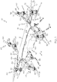
Fig. 1 is a front perspective view of one example of the disclosed unmanned aerial vehicle; -
Fig. 2 is a front elevational view of the unmanned aerial vehicle ofFig. 1 ; -
Fig. 3 is a side elevational view of the unmanned aerial vehicle ofFig. 1 ; -
Fig. 4 is a top plan view of the unmanned aerial vehicle ofFig. 1 ; -
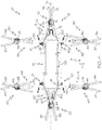
Fig. 5 is a front elevational view of the unmanned aerial vehicle ofFig. 1 , but without the curved leading-edge fairing and the boom fairings, thereby showing internal structure; -
Fig. 6 is a front elevational view of the unmanned aerial vehicle ofFig. 5 ; -
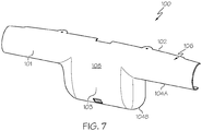
Fig. 7 is a front perspective view of the curved leading-edge fairing of the unmanned aerial vehicle ofFig. 1 ; -
Figs. 8 and 9 are front perspective view of the boom fairings of the unmanned aerial vehicle ofFig. 1 ; -
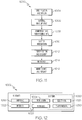
Fig. 10 is a flow diagram depicting one example of the disclosed method for reducing drag during flight of an unmanned aerial vehicle; -
Fig. 11 is a flow diagram of an aircraft manufacturing and service methodology; and -
Fig. 12 is a block diagram of an aircraft. - Disclosed are unmanned aerial vehicles that have been designed and configured for forward flight with a significantly reduced pitch attitude. For example, the disclosed unmanned aerial vehicles may have a pitch angle about the frame axis of less than 13 degrees (e.g., about 10 degrees or less) when traveling in a forward direction at airspeeds up to about 50 knots. As such, the disclosed unmanned aerial vehicles may experience significantly less drag, thereby significantly increasing service duration of the unmanned aerial vehicles.
- Referring to
Figs. 1-6 , one example of the disclosed unmanned aerial vehicle, generally designated 10, includes aframe 12, a firstforward rotor assembly 30, a secondforward rotor assembly 40, a firstaft rotor assembly 50, a secondaft rotor assembly 60, a firstoutboard rotor assembly 70, a secondoutboard rotor assembly 80, acompartment 90, a curved leading-edge fairing 100, a firstforward boom fairing 120 and a secondforward boom fairing 150. The unmannedaerial vehicle 10 may further include a first aft boom fairing 130 and a second aft boom fairing 160. In other words, the unmannedaerial vehicle 10 includes a pair offorward rotor assemblies aft rotor assemblies outboard rotor assemblies forward boom fairings aft boom fairings aerial vehicle 10 without departing from the scope of the present disclosure. - As best shown in
Figs. 5 and6 , theframe 12 of the disclosed unmannedaerial vehicle 10 may include a truss 22 (e.g., a Brown-type truss) and may be elongated along a frame axis AF, which may be orthogonal to (e.g., lateral relative to) the forward direction F the unmannedaerial vehicle 10. Therefore, theframe 12 may have aleft end portion 18 and aright end portion 20 that is axially opposed from theleft end portion 18 relative to the frame axis AF. Theframe 12 may further have a leadingside 14 and anaft side 16, as well as anunderside 24 and atopside 26. - Still referring to
Figs. 1-6 , the firstforward rotor assembly 30 of the disclosed unmannedaerial vehicle 10 is connected to theleft end portion 18 of theframe 12 on the leadingside 14 of theframe 12. For example, the unmannedaerial vehicle 10 may include a firstforward boom 32 having a proximal end portion 31 (Fig. 4 ) connected to theleft end portion 18 of theframe 12 and a distal end portion 33 (Fig. 4 ) connected to the firstforward rotor assembly 30. - The first
forward rotor assembly 30 may include arotor shaft 34, arotor 36, and amotor 38, as best shown inFigs. 1-3 . Therotor shaft 34 may define a rotor shaft axis AR1, which may be slightly tilted inward (i.e., toward theright end portion 20 of the frame 12) and slightly tilted in the forward direction F. Therotor shaft 34 may be rotatable about the rotor shaft AR1. Therotor 36 may be fixedly connected to therotor shaft 34 such that therotor 36 rotates with therotor shaft 34. The motor 38 (e.g., a battery-powered electric motor) may be operatively connected to therotor shaft 34 to cause therotor shaft 34 and, thus, therotor 36, to rotate about the rotor shaft axis AR1. - In one particular implementation, the first
forward rotor assembly 30 may include a pair orrotors 36, 37 (e.g., a pair of co-rotating rotors (same direction)). Thesecond rotor 37 of the firstforward rotor assembly 30 may be fixedly connected to asecond rotor shaft 35 and may be powered by asecond motor 39. Themotors forward rotor assembly 30 may be configured as a coaxial motor stack. - The second
forward rotor assembly 40 of the disclosed unmannedaerial vehicle 10 may be connected to theright end portion 20 of theframe 12 on the leadingside 14 of theframe 12. For example, the unmannedaerial vehicle 10 may include a secondforward boom 42 having a proximal end portion 41 (Fig. 4 ) connected to theright end portion 20 of theframe 12 and a distal end portion 43 (Fig. 4 ) connected to the secondforward rotor assembly 40. Therefore, the unmannedaerial vehicle 10 may have a pair offorward booms - The second
forward rotor assembly 40 may include arotor shaft 44, arotor 46, and amotor 48. Therotor shaft 44 may define a rotor shaft axis AR2, which may be slightly tilted inward (i.e., toward theleft end portion 18 of the frame 12) and slightly tilted in the forward direction F. Therotor shaft 44 may be rotatable about the rotor shaft AR2. Therotor 46 may be fixedly connected to therotor shaft 44 such that therotor 46 rotates with therotor shaft 44. The motor 48 (e.g., a battery-powered electric motor) may be operatively connected to therotor shaft 44 to cause therotor shaft 44 and, thus, therotor 46, to rotate about the rotor shaft axis AR2. - In one particular implementation, the second
forward rotor assembly 40 may include a pair orrotors 46, 47 (e.g., a pair of co-rotating rotors (same direction)). Thesecond rotor 47 of the secondforward rotor assembly 40 may be fixedly connected to asecond rotor shaft 45 and may be powered by asecond motor 49. Themotors forward rotor assembly 40 may be configured as a coaxial motor stack. - The first
aft rotor assembly 50 of the disclosed unmannedaerial vehicle 10 may be connected to theleft end portion 18 of theframe 12 on theaft side 16 of theframe 12. For example, the unmannedaerial vehicle 10 may include afirst aft boom 52 having a proximal end portion 51 (Fig. 4 ) connected to theleft end portion 18 of theframe 12 and a distal end portion 53 (Fig. 4 ) connected to the firstaft rotor assembly 50. - The first
aft rotor assembly 50 may include arotor shaft 54, arotor 56, and amotor 58. Therotor shaft 54 may define a rotor shaft axis AR3, which may be slightly tilted inward (i.e., toward theright end portion 20 of the frame 12). Therotor shaft 54 may be rotatable about the rotor shaft AR3. Therotor 56 may be fixedly connected to therotor shaft 54 such that therotor 56 rotates with therotor shaft 54. The motor 58 (e.g., a battery-powered electric motor) may be operatively connected to therotor shaft 54 to cause therotor shaft 54 and, thus, therotor 56, to rotate about the rotor shaft axis AR3. - In one particular implementation, the first
aft rotor assembly 50 may include a pair orrotors 56, 57 (e.g., a pair of co-rotating rotors (same direction)). Thesecond rotor 57 of the firstaft rotor assembly 50 may be fixedly connected to asecond rotor shaft 55 and may be powered by asecond motor 59. Themotors aft rotor assembly 50 may be configured as a coaxial motor stack. - The second
aft rotor assembly 60 of the disclosed unmannedaerial vehicle 10 may be connected to theright end portion 20 of theframe 12 on theaft side 16 of theframe 12. For example, the unmannedaerial vehicle 10 may include asecond aft boom 62 having a proximal end portion 61 (Fig. 4 ) connected to theright end portion 20 of theframe 12 and a distal end portion 63 (Fig. 4 ) connected to the secondaft rotor assembly 60. Therefore, the unmannedaerial vehicle 10 may have a pair ofaft booms - The second
aft rotor assembly 60 may include arotor shaft 64, a rotor 66, and amotor 68. Therotor shaft 64 may define a rotor shaft axis AR4, which may be slightly tilted inward (i.e., toward theleft end portion 18 of the frame 12). Therotor shaft 64 may be rotatable about the rotor shaft AR4. The rotor 66 may be fixedly connected to therotor shaft 64 such that the rotor 66 rotates with therotor shaft 64. The motor 68 (e.g., a battery-powered electric motor) may be operatively connected to therotor shaft 64 to cause therotor shaft 64 and, thus, the rotor 66, to rotate about the rotor shaft axis AR4. - In one particular implementation, the second
aft rotor assembly 60 may include a pair or rotors 66, 67 (e.g., a pair of co-rotating rotors (same direction)). Thesecond rotor 67 of the secondaft rotor assembly 60 may be fixedly connected to asecond rotor shaft 65 and may be powered by asecond motor 69. Themotors aft rotor assembly 60 may be configured as a coaxial motor stack. - The first
outboard rotor assembly 70 of the disclosed unmannedaerial vehicle 10 may be connected to theleft end portion 18 of theframe 12 and may protrude laterally outward from the frame 12 (e.g., along the frame axis AF). For example, the unmannedaerial vehicle 10 may include a firstoutboard boom 72 having a leadingside 110 and anaft side 112, as well as aproximal end portion 114 and adistal end portion 116 opposed from theproximal end portion 114. Theproximal end portion 114 of the firstoutboard boom 72 may be connected to theleft end portion 18 of theframe 12 and thedistal end portion 116 of the firstoutboard boom 72 may be connected to the firstoutboard rotor assembly 70. - The first
outboard rotor assembly 70 may include arotor shaft 74, arotor 76, and amotor 78. Therotor shaft 74 may define a rotor shaft axis AR5, which may be slightly tilted in the forward direction F. Therotor shaft 74 may be rotatable about the rotor shaft AR5. Therotor 76 may be fixedly connected to therotor shaft 74 such that therotor 76 rotates with therotor shaft 74. The motor 78 (e.g., a battery-powered electric motor) may be operatively connected to therotor shaft 74 to cause therotor shaft 74 and, thus, therotor 76, to rotate about the rotor shaft axis AR5. - In one particular implementation, the first
outboard rotor assembly 70 may include a pair orrotors 76, 77 (e.g., a pair of contra-rotating rotors). Thesecond rotor 77 of the firstoutboard rotor assembly 70 may be fixedly connected to asecond rotor shaft 75 and may be powered by asecond motor 79. Themotors outboard rotor assembly 70 may be configured as a coaxial motor stack. - The second
outboard rotor assembly 80 of the disclosed unmannedaerial vehicle 10 may be connected to theright end portion 20 of theframe 12 and may protrude laterally outward from the frame 12 (e.g., along the frame axis AF). For example, the unmannedaerial vehicle 10 may include a secondoutboard boom 82 having a leadingside 140 and anaft side 142, as well as aproximal end portion 144 and adistal end portion 146 opposed from theproximal end portion 144. Theproximal end portion 144 of the secondoutboard boom 82 may be connected to theright end portion 20 of theframe 12 and thedistal end portion 146 of the secondoutboard boom 82 may be connected to the secondoutboard rotor assembly 80. Therefore, the unmannedaerial vehicle 10 may have a pair ofoutboard booms - The second
outboard rotor assembly 80 may include arotor shaft 84, arotor 86, and amotor 88. Therotor shaft 84 may define a rotor shaft axis AR6, which may be slightly tilted in the forward direction F. Therotor shaft 84 may be rotatable about the rotor shaft AR6. Therotor 86 may be fixedly connected to therotor shaft 84 such that therotor 86 rotates with therotor shaft 84. The motor 88 (e.g., a battery-powered electric motor) may be operatively connected to therotor shaft 84 to cause therotor shaft 84 and, thus, therotor 86, to rotate about the rotor shaft axis AR6. - In one particular implementation, the second
outboard rotor assembly 80 may include a pair orrotors 86, 87 (e.g., a pair of contra-rotating rotors). Thesecond rotor 87 of the secondoutboard rotor assembly 80 may be fixedly connected to asecond rotor shaft 85 and may be powered by asecond motor 89. Themotors outboard rotor assembly 80 may be configured as a coaxial motor stack. - The
compartment 90 of the disclosed unmannedaerial vehicle 10 has a leadingside 92 and an aft side opposed from the leadingside 92, and is connected to theframe 12. As one example, thecompartment 90 may be connected to theunderside 24 of theframe 12, as shown inFigs. 5 and6 . As another example, thecompartment 90 may be connected to thetopside 26 of theframe 12. - The
compartment 90 may define a partially enclosed or a fully enclosed space for storing various items on the unmannedaerial vehicle 10. As one example, thecompartment 90 may be a battery compartment, and abattery 94 may be received (e.g., housed) in thecompartment 90. Thebattery 94 may be used to power thevarious motors aerial vehicle 10. As another example, thecompartment 90 may be a payload compartment. As yet another example, thecompartment 90 may be configured for receiving both abattery 94 and a payload (not shown). - The unmanned
aerial vehicle 10 may further includelanding gear 96. Thelanding gear 96 may be connected to theframe 12, such as to theunderside 24 of theframe 12. With thelanding gear 96 positioned on theunderside 24 of theframe 12, thelanding gear 96 may elevate theframe 12 above any structure (e.g., landing pad (not shown)) upon which the unmannedaerial vehicle 10 is resting. - The curved leading-
edge fairing 100 of the disclosed unmannedaerial vehicle 10 is positioned over at least a portion of the leadingside 14 of theframe 12 and at least a portion of the leadingside 92 of thecompartment 90. In one particular construction, the curved leading-edge fairing 100 substantially completely covers (e.g., covers at least 90 percent of) the leadingside 14 of theframe 12 and the leadingside 92 of thecompartment 90. For example, the curved leading-edge fairing 100 may be disposed relative to theframe 12 such that afirst portion 101 of the curved leading-edge fairing 100 extends over the leadingside 14 of theframe 12 and asecond portion 103 extends over the leadingside 92 of thecompartment 90. - As shown in
Fig. 7 , the curved leading-edge fairing 100 may include anupper edge 102, alower edge 104A associated with thefirst portion 101 of the curved leading-edge fairing 100, and alower edge 104B associated with thesecond portion 103 of the curved leading-edge fairing 100, and may have acontinuous curvature 106 from theupper edge 102 to thelower edge 104A and acontinuous curvature 106 from theupper edge 102 to thelower edge 104B. For example, from theupper edge 102 to thelower edge 104A, the curved leading-edge fairing 100 has a minimum radius of curvature of at least about 7,62 cm (i.e. about 3 inches). Therefore, the curved leading-edge fairing 100 may have an aerodynamic shape that reduces drag during flight of the unmannedaerial vehicle 10 in a forward direction F (Fig. 1 ) to enable a substantially level flight profile. Within examples, the substantially level flight profile is a pitch angle Θ of theframe 12 about the frame axis AF, during flight in a forward direction F, of 0 degrees up to about 13 degrees, and more preferably a pitch angle Θ of 0 to about 10 degrees. - The curved leading-
edge fairing 100 may be constructed from various materials without departing from the scope of the present disclosure. Appropriate material selection may ensure that theouter surface 108 of the curved leading-edge fairing 100 is sufficiently smooth and aerodynamic. Examples of suitable materials include, without limitation, metals and metal alloys (e.g., titanium alloys), polymeric materials, and composite materials (e.g., carbon fiber-reinforced epoxy composites). - The first forward boom fairing 120 of the disclosed unmanned
aerial vehicle 10 is positioned over at least a portion of the leadingside 110 of the firstoutboard boom 72. In one particular construction, the first forward boom fairing 120 substantially completely covers the leadingside 110 of the firstoutboard boom 72. - As shown in
Fig. 8 , the first forward boom fairing 120 may include anupper edge 122 and alower edge 124, and may have acontinuous curvature 126 from theupper edge 122 to thelower edge 124. In one particular construction, the first forward boom fairing 120 may have a first radius of curvature RL1 proximate (i.e., at or near) the proximal end portion 114 (Fig. 6 ) of the firstoutboard boom 72 and a second radius of curvature RL2 proximate the distal end portion 116 (Fig. 6 ) of the firstoutboard boom 72, and wherein the first radius of curvature RL1 is substantially greater (e.g., at least 20 percent greater, such as at least 50 percent greater) than the second radius of curvature RL2. For example, the first radius of curvature RL1 may be about 14,61 cm (i.e. about 5.75 inches) and the second radius of curvature RL2 may be about 7,62 cm (i.e. about 3 inches). Therefore, the first forward boom fairing 120 may have an aerodynamic shape that reduces drag during flight of the unmannedaerial vehicle 10 in a forward direction F (Fig. 1 ) to enable a substantially level flight profile. - The second forward boom fairing 150 of the disclosed unmanned
aerial vehicle 10 is positioned over at least a portion of the leadingside 110 of the secondoutboard boom 82. In one particular construction, the second forward boom fairing 150 substantially completely covers the leadingside 140 of the secondoutboard boom 82. - As shown in
Fig. 9 , the second forward boom fairing 150 may include anupper edge 152 and alower edge 154, and may have acontinuous curvature 156 from theupper edge 152 to thelower edge 154. In one particular construction, the second forward boom fairing 150 may have a first radius of curvature RR1 proximate (i.e., at or near) the proximal end portion 144 (Fig. 6 ) of the second forward boom fairing 150 and a second radius of curvature RR2 proximate the distal end portion 146 (Fig. 6 ) of the second forward boom fairing 150, and wherein the first radius of curvature RR1 is substantially greater (e.g., at least 20 percent greater, such as at least 50 percent greater) than the second radius of curvature RR2. For example, the first radius of curvature RR1 may be about 14,61 cm (i.e. about 5.75 inches) and the second radius of curvature RR2 may be about 7,62 cm (i.e. about 3 inches). Therefore, the second forward boom fairing 150 may have an aerodynamic shape that reduces drag during flight of the unmannedaerial vehicle 10 in a forward direction F (Fig. 1 ) to enable a substantially level flight profile. - The first aft boom fairing 130 of the disclosed unmanned
aerial vehicle 10 is positioned over at least a portion of theaft side 112 of the firstoutboard boom 72. The first aft boom fairing 130 may be sized, shaped and configured in a manner similar to the first forward boom fairing 120 on theforward side 110 of the firstoutboard boom 72. - The second aft boom fairing 160 of the disclosed unmanned
aerial vehicle 10 is positioned over at least a portion of theaft side 142 of the secondoutboard boom 82. The second aft boom fairing 160 may be sized, shaped and configured in a manner similar to the second forward boom fairing 150 on theforward side 140 of the secondoutboard boom 82. - The first aft boom fairing 130 and the second aft boom fairing 160 may facilitate drag reduction. Additionally, the first aft boom fairing 130 and the second aft boom fairing 160 may enhance handling qualities in hover. For example, the first forward boom fairing 120 and the second forward boom fairing 150 may be identical to but opposite of the first aft boom fairing 130 and the second
aft boom fairing 160. Therefore, in hover, the first forward boom fairing 120, the second forward boom fairing 150, the first aft boom fairing 130, and the second aft boom fairing 160 may passively have equal and opposite forces in the horizontal direction, helping the flight control system to hold position above a point on the ground. - The presence on the unmanned
aerial vehicle 10 of the curved leading-edge fairing 100, the first forward boom fairing 120, the second forward boom fairing 150, the first aft boom fairing 130, and/or the second aft boom fairing 160 may significantly reduce drag when the unmannedaerial vehicle 10 moves in a forward direction F, thereby reducing power consumption (e.g., up to about 20 percent) and increasing service duration of the unmannedaerial vehicle 10. Therefore, the pitch angle Θ (i.e., the angle between the forward direction F and the pitch attitude P of theframe 12 about the frame axis AF) of the unmannedaerial vehicle 10 during flight in the forward direction F can be significantly reduced (e.g., a predetermined reduction in pitch angle Θ can be achieved). Within examples, the predetermined reduction in pitch angle Θ is a reduction (compared to a pitch angle of a UAV configured without the presence of the disclosed fairings) in pitch angle Θ of about 2 to 5 degrees. For example, a reduction in pitch angle Θ of up to about 5 degrees may be achieved, such as a 4 degree reduction in pitch angle Θ or a 3 degree reduction in pitch angle Θ or a 2 degree reduction in pitch angle Θ. The reduced drag enables the predetermined reduction in the pitch angle Θ that is effective to yield a reduced pitch angle Θ of theframe 12 about the frame axis AF that is at most 13 degrees. Within examples, the reduced pitch angle Θ is between about 10 and 13 degrees. - In one expression, the pitch angle Θ of the
frame 12 about the frame axis AF is at most about 13 degrees when the unmannedaerial vehicle 10 is traveling in a forward direction F at airspeeds up to about 50 knots. In another expression, the pitch angle Θ of theframe 12 about the frame axis AF is at most about 12 degrees when the unmannedaerial vehicle 10 is traveling in a forward direction F at airspeeds up to about 50 knots. In another expression, the pitch angle Θ of theframe 12 about the frame axis AF is at most about 11 degrees when the unmannedaerial vehicle 10 is traveling in a forward direction F at airspeeds up to about 50 knots. In another expression, the pitch angle Θ of theframe 12 about the frame axis AF is at most about 10 degrees when the unmannedaerial vehicle 10 is traveling in a forward direction F at airspeeds up to about 50 knots. - As mentioned above, the presence on the unmanned
aerial vehicle 10 of the curved leading-edge fairing 100, the first forward boom fairing 120, the second forward boom fairing 150, the first aft boom fairing 130, and the second aft boom fairing 160 helps to reduce power consumption and increase service duration of the unmannedaerial vehicle 10. Furthermore, the presence on the unmannedaerial vehicle 10 of the curved leading-edge fairing 100, the first forward boom fairing 120, the second forward boom fairing 150, the first aft boom fairing 130, and the second aft boom fairing 160 may significantly reduce noise when the unmannedaerial vehicle 10 moves in a forward direction F. Without being limited to any particular theory, it is presently believed that the presence of the curved leading-edge fairing 100, the first forward boom fairing 120, the second forward boom fairing 150, the first aft boom fairing 130, and the second aft boom fairing 160 enhances the stability (e.g., closer to neutral stability) of the unmannedaerial vehicle 10, thereby contributing to UAV/rotor noise reduction. - Also disclosed are methods for reducing drag during flight of an unmanned aerial vehicle that includes a frame elongated along a frame axis, the frame comprising a leading side and an aft side, the frame further comprising a left end portion and a right end portion, at least two rotor assemblies connected to the left end portion of the frame by way of at least two first booms, and at least two rotor assemblies connected to the right end portion of the frame by way of at least two second booms.
- Referring to
Fig. 10 , one example of the disclosed method for reducing drag during flight of an unmanned aerial vehicle, generally designated 500, begins atBlock 510 with the step of positioning a curved leading-edge fairing 100 over at least a portion of the leadingside 14 of theframe 12. AtBlock 520, a first forward boom fairing 120 is positioned over the firstoutboard boom 72. AtBlock 530, a second forward boom fairing 150 is positioned over the secondoutboard boom 82. AtBlock 540, a first aft boom fairing 130 may be positioned over the firstoutboard boom 72. Atblock 550, a second aft boom fairing 160 may be positioned over the secondoutboard boom 82. - Examples of the disclosure may be described in the context of an aircraft manufacturing and
service method 1000, as shown inFig. 11 , and anaircraft 1002, as shown inFig. 12 . During pre-production, the aircraft manufacturing andservice method 1000 may include specification anddesign 1004 of theaircraft 1002 andmaterial procurement 1006. During production, component/subassembly manufacturing 1008 andsystem integration 1010 of theaircraft 1002 takes place. Thereafter, theaircraft 1002 may go through certification anddelivery 1012 in order to be placed inservice 1014. While in service by a customer, theaircraft 1002 is scheduled for routine maintenance andservice 1016, which may also include modification, reconfiguration, refurbishment and the like. - Each of the processes of
method 1000 may be performed or carried out by a system integrator, a third party, and/or an operator (e.g., a customer). For the purposes of this description, a system integrator may include without limitation any number of aircraft manufacturers and major-system subcontractors; a third party may include without limitation any number of venders, subcontractors, and suppliers; and an operator may be an airline, leasing company, military entity, service organization, and so on. - As shown in
Fig. 12 , theaircraft 1002 produced byexample method 1000 may include anairframe 1018 with a plurality ofsystems 1020 and an interior 1022. Examples of the plurality ofsystems 1020 may include one or more of apropulsion system 1024, anelectrical system 1026, ahydraulic system 1028, and anenvironmental system 1030. Any number of other systems may be included. - The disclosed unmanned aerial vehicle and/or method for reducing drag during flight of an unmanned aerial vehicle may be employed during any one or more of the stages of the aircraft manufacturing and
service method 1000. As one example, the disclosed unmanned aerial vehicle and/or method for reducing drag during flight of an unmanned aerial vehicle may be employed duringmaterial procurement 1006. As another example, components or subassemblies corresponding to component/subassembly manufacturing 1008,system integration 1010, and or maintenance andservice 1016 may be fabricated or manufactured using the disclosed unmanned aerial vehicle and/or method for reducing drag during flight of an unmanned aerial vehicle. As another example, theairframe 1018 and the interior 1022 may be constructed using the disclosed unmanned aerial vehicle and/or method for reducing drag during flight of an unmanned aerial vehicle. Also, one or more apparatus examples, method examples, or a combination thereof may be utilized during component/subassembly manufacturing 1008 and/orsystem integration 1010, for example, by substantially expediting assembly of or reducing the cost of anaircraft 1002, such as theairframe 1018 and/or the interior 1022. Similarly, one or more of system examples, method examples, or a combination thereof may be utilized while theaircraft 1002 is in service, for example and without limitation, to maintenance andservice 1016. The disclosed unmanned aerial vehicle and/or method for reducing drag during flight of an unmanned aerial vehicle are described in the context of an aircraft; however, one of ordinary skill in the art will readily recognize that the disclosed unmanned aerial vehicle and/or method for reducing drag during flight of an unmanned aerial vehicle may be utilized for a variety of applications. For example, the disclosed unmanned aerial vehicle and/or method for reducing drag during flight of an unmanned aerial vehicle may be implemented in various types of vehicles, including, for example, helicopters, passenger ships, automobiles and the like. - Further, the disclosure comprises embodiments according to the following clauses:
- Clause 1. An unmanned aerial vehicle (10) comprising:
- a frame (12) elongated along a frame axis (AF), the frame (12) comprising a leading side (14) and an aft side (16), the frame (12) further comprising a left end portion (18) and a right end portion (20);
- a first forward rotor assembly (30) connected to the left end portion (18) of the frame (12);
- a second forward rotor assembly (40) connected to the right end portion (20) of the frame (12), the first forward rotor assembly (30) and the second forward rotor assembly (40) being positioned on the leading side (14) of the frame (12);
- a compartment (90) connected to the frame (12), the compartment (90) comprising a leading side (92); and
- a curved leading-edge fairing (100) disposed on the frame (12), wherein a portion of the curved leading-edge fairing extends to cover the leading side (92) of the compartment (90), and wherein the curved leading-edge fairing reduces drag during flight in a forward direction to enable a substantially level flight profile.
- Clause 2. The unmanned aerial vehicle (10) of Clause 1 wherein the compartment (90) is a battery compartment.
- Clause 3. The unmanned aerial vehicle (10) of Clause 1 or Clause 2 wherein the compartment (90) is positioned on an underside (24) of the frame (12).
- Clause 4. The unmanned aerial vehicle (10) of Clause 3 further comprising landing gear (96), the landing gear (96) being positioned on the underside (24) of the frame (12).
- Clause 5. The unmanned aerial vehicle (10) of any of Clauses 1-4 further comprising a battery (94) housed in the compartment (90).
- Clause 6. The unmanned aerial vehicle (10) of any of Clauses 1-5 wherein the curved leading-edge fairing (100) comprises an upper edge (102), a lower edge (104), and a continuous curvature (106) from the upper edge (102) to the lower edge (104).
- Clause 7. The unmanned aerial vehicle (10) of any of Clauses 1-6 wherein the curved leading-edge fairing (100) substantially completely covers the leading side (14) of the frame (12) and the leading side (92) of the compartment (90).
- Clause 8. The unmanned aerial vehicle (10) of any of Clauses 1-7 wherein the curved leading-edge fairing (100) is configured to reduce a pitch angle (Θ) of the frame (12) about the frame axis (AF) to less than 13 degrees when the unmanned aerial vehicle (10) is traveling in a forward direction (F) at airspeeds up to about 50 knots.
- Clause 9. The unmanned aerial vehicle (10) of any of Clauses 1-8 wherein a reduced pitch angle (Θ) of the frame (12) about the frame axis (AF) is at most about 10 degrees when the unmanned aerial vehicle (10) is traveling in a forward direction (F) at airspeeds up to about 50 knots.
-
Clause 10. The unmanned aerial vehicle (10) of any of Clauses 1-9 further comprising:- a pair of outboard rotor assemblies disposed on a pair of outboard booms; and
- a pair of forward boom fairings disposed on the pair of outboard booms.
- Clause 11. The unmanned aerial vehicle (10) of
Clause 10 wherein the curved leading edge fairing (100) and the pair of forward boom fairings are configured to reduce drag during flight in the forward direction to enable a predetermined reduction in a pitch angle (Θ) of the frame (12) about the frame axis (AF) when the unmanned aerial vehicle (10) moves in the forward direction (F). -
Clause 12. The unmanned aerial vehicle (10) of Clause 11 wherein a reduced pitch angle (Θ) of the frame (12) about the frame axis (AF) is at most 13 degrees. - Clause 13. The unmanned aerial vehicle (10) of
Clause 12 wherein the reduced pitch angle is between about 10 and 13 degrees. -
Clause 14. The unmanned aerial vehicle (10) of any of Clauses 10-13 wherein:- the pair of outboard booms comprises a first outboard boom (72) comprising a leading side (110) and an aft side (112), the first outboard boom (72) further comprising a proximal end portion (114) and a distal end portion (116) opposed from the proximal end portion (114), the proximal end portion (114) of the first outboard boom (72) being connected to the left end portion (18) of the frame (12);
- the pair of outboard rotor assemblies comprises a first outboard rotor assembly (70) connected to the distal end portion (116) of the first outboard boom (72); and
- the pair of forward boom fairings comprises a first forward boom fairing (120) positioned over at least a portion of the leading side (110) of the first outboard boom (72).
- Clause 15. The unmanned aerial vehicle (10) of
Clause 14 wherein the first forward boom fairing (120) comprises an upper edge (122), a lower edge (124), and a continuous curvature (126) from the upper edge (122) to the lower edge (124). -
Clause 16. The unmanned aerial vehicle (10) ofClause 14 or Clause 15 wherein the first forward boom fairing (120) comprises a first radius of curvature proximate the proximal end portion (114) of the first outboard boom (72) and a second radius of curvature proximate the distal end portion (116) of the first outboard boom (72), and wherein the first radius of curvature is substantially greater than the second radius of curvature. - Clause 17. The unmanned aerial vehicle (10) of any of Clauses 14-16 wherein:
- the pair of outboard booms further comprises a second outboard boom (82) comprising a leading side (140) and an aft side (142), the second outboard boom (82) further comprising a proximal end portion (144) and a distal end portion (146) opposed from the proximal end portion (144), the proximal end portion (144) of the second outboard boom (82) being connected to the right end portion (20) of the frame (12);
- the pair of outboard rotor assemblies further comprises a second outboard rotor assembly (80) connected to the distal end portion (146) of the second outboard boom (82); and
- the pair of forward boom fairings further comprises a second forward boom fairing (150) positioned over at least a portion of the leading side (140) of the second outboard boom (82).
-
Clause 18. The unmanned aerial vehicle (10) of Clause 17 wherein the second forward boom fairing (150) comprises an upper edge (152), a lower edge (154), and a continuous curvature (156) from the upper edge (152) to the lower edge (154). - Clause 19. The unmanned aerial vehicle (10) of Clause 17 or
Clause 18 wherein the second forward boom fairing (150) comprises a first radius of curvature proximate the proximal end portion (144) of the second outboard boom (82) and a second radius of curvature proximate the distal end portion (146) of the second outboard boom (82), and wherein the first radius of curvature is substantially greater than the second radius of curvature. -
Clause 20. The unmanned aerial vehicle (10) of any of Clauses 17-19 further comprising a pair of aft boom fairings disposed on the pair of outboard booms, wherein the pair of aft boom fairings comprises a first aft boom fairing (130) positioned over at least a portion of an aft side (112) of a first outboard boom (72) and a second aft boom fairing (160) positioned over at least a portion of an aft side (142) of a second outboard boom (82). - Clause 21. The unmanned aerial vehicle (10) of any of Clauses 10-20 wherein each forward boom fairing of the pair of forward boom fairings is configured to reduce drag when the unmanned aerial vehicle (10) moves in a forward direction (F).
-
Clause 22. The unmanned aerial vehicle (10) of any of Clauses 10-19 further comprising:
a pair of aft boom fairings disposed on the pair of outboard booms. - Clause 23. The unmanned aerial vehicle (10) of any of Clauses 1-22 wherein the frame (12) comprises a truss (22).
-
Clause 24. The unmanned aerial vehicle (10) of any of Clauses 1-9 further comprising:- a first forward boom (32) connecting the first forward rotor (30) assembly to the left end portion (18) of the frame (12); and
- a second forward boom (42) connecting the second forward rotor (40) assembly to the right end portion (20) of the frame (12).
- Clause 25. The unmanned aerial vehicle (10) of any of Clauses 1-24 wherein each of the first forward rotor assembly (30) and the second forward rotor assembly (40) comprises:
- a rotor shaft (34, 44) defining a rotor shaft axis (AR1, AR2);
- a rotor (36, 46) connected to the rotor shaft (34, 44); and
- a motor (38, 48) operatively connected to the rotor shaft (34, 44) to cause the rotor shaft (34, 44, 54, 64) to rotate about the rotor shaft axis (AR1, AR2).
-
Clause 26. The unmanned aerial vehicle (10) of any of Clauses 1-25 wherein each of the first forward rotor assembly (30) and the second forward rotor assembly (40) comprises a pair or rotors (36, 37; 46, 47). - Clause 27. The unmanned aerial vehicle (10) of any of Clauses 1-26 further comprising:
- a first aft rotor assembly (50) connected to the left end portion (18) of the frame (12); and
- a second aft rotor assembly (60) connected to the right end portion (20) of the frame (12), the first aft rotor assembly (50) and the second aft rotor assembly (60) being positioned on the aft side (16) of the frame (12).
- Clause 28. The unmanned aerial vehicle (10) of Clause 27 further comprising:
- a first aft boom (52) connecting the first aft rotor assembly (50) to the left end portion (18) of the frame (12); and
- a second aft boom (62) connecting the second aft rotor assembly (60) to the right end portion (20) of the frame (12).
- Clause 29. The unmanned aerial vehicle (10) of Clause 27 or Clause 28 wherein each of the first aft rotor assembly (50) and the second aft rotor (60) assembly comprises:
- a rotor shaft (54, 64) defining a rotor shaft axis (AR3, AR4);
- a rotor (56, 66) connected to the rotor shaft (54, 64); and
- a motor (58, 68) operatively connected to the rotor shaft (54, 64) to cause the rotor shaft (54, 64) to rotate about the rotor shaft axis (AR3, AR4).
-
Clause 30. The unmanned aerial vehicle (10) of any of Clauses 27-29 wherein each of the first aft rotor assembly (50) and the second aft rotor assembly (60) comprises a pair or rotors (56, 57; 66, 67). - Clause 31. An unmanned aerial vehicle (10) comprising:
- a frame (12) elongated along a frame axis, the frame comprising a leading side and an aft side, the frame further comprising a left end portion and a right end portion axially opposed from the left end portion relative to the frame axis;
- a first forward rotor assembly (30) connected to the left end portion of the frame by way of a first forward boom;
- a first aft rotor assembly (50) connected to the left end portion of the frame by way of a first aft boom;
- a first outboard rotor assembly (70) connected to the left end portion of the frame by way of a first outboard boom, the first outboard boom comprising a leading side and an aft side;
- a first forward boom fairing (120) positioned over the leading side of the first outboard boom;
- a second forward rotor (40) assembly connected to the right end portion of the frame by way of a second forward boom;
- a second aft rotor assembly (60) connected to the right end portion of the frame by way of a second aft boom;
- a second outboard rotor assembly (80) connected to the right end portion of the frame by way of a second outboard boom, the second outboard boom comprising a leading side and an aft side;
- a second forward boom fairing (150) positioned over the leading side of the second outboard boom;
- a compartment (90) connected to the frame, the compartment comprising a leading side; and
- a curved leading-edge fairing (100) disposed on the frame (12), wherein a portion of the curved leading-edge fairing extends to cover the leading side (92) of the compartment (90).
-
Clause 32. The unmanned aerial vehicle (10) of Clause 31 further comprising:- a first aft boom fairing positioned over the aft side of the first outboard boom; and
- a second aft boom fairing positioned over the aft side of the second outboard boom.
-
Clause 33. The unmanned aerial vehicle (10) ofClause 32 wherein a pitch angle (Θ) of the frame (12) about the frame axis (AF) is less than 13 degrees when the unmanned aerial vehicle (10) is traveling in a forward direction (F) at airspeeds up to about 50 knots. -
Clause 34. The unmanned aerial vehicle (10) ofClause 32 orClause 33 wherein a pitch angle (Θ) of the frame (12) about the frame axis (AF) is at most about 10 degrees when the unmanned aerial vehicle (10) is traveling in a forward direction (F) at airspeeds up to about 50 knots. -
Clause 35. A method (500) for reducing drag during flight of an unmanned aerial vehicle comprising a frame elongated along a frame axis, the frame comprising a leading side and an aft side, the frame further comprising a left end portion and a right end portion, at least two rotor assemblies connected to the left end portion of the frame by way of at least two first booms, and at least two rotor assemblies connected to the right end portion of the frame by way of at least two second booms, the method comprising:- positioning (510) a curved leading-edge fairing over at least a portion of the leading side of the frame;
- positioning (520) a first forward boom fairing over a boom of the at least two first booms; and
- positioning (530) a second forward boom fairing over a boom of the at least two second booms.
-
Clause 36. The method (500) ofClause 35 further comprising:- positioning (540) a first aft boom fairing over the boom of the at least two first booms; and
- positioning (550) a second aft boom fairing over the boom of the at least two second booms.
-
Clause 37. The method ofClause 35 orClause 36 wherein positioning (510) a curved leading-edge fairing over at least a portion of the leading side of the frame comprises positioning the curved leading-edge fairing over a leading side of a battery compartment connected to the frame. -
Clause 38. A method (500) for reducing drag during flight of an unmanned aerial vehicle, the vehicle comprising a frame elongated along a frame axis, the frame comprising a leading side and an aft side, the frame further comprising a left end portion and a right end portion, at least one rotor assembly connected to the left end portion of the frame by way of at least a first outboard boom, and at least one rotor assemblies connected to the right end portion of the frame by way of at least a second outboard boom, the method comprising:- positioning (510) a curved leading-edge fairing over at least a portion of the leading side of the frame;
- positioning (520) a first forward boom fairing over at least a portion of the leading side of the first outboard boom; and
- positioning (530) a second forward boom fairing over at least a portion of the leading side of the second outboard boom.
-
Clause 39. The method (500) ofClause 38 further comprising:- positioning (540) a first aft boom fairing over the aft side of the first outboard boom; and
- positioning (550) a second aft boom fairing over the aft side of the second outboard boom of the at least two second booms.
-
Clause 40. The method (500) ofClause 38 orClause 39 wherein positioning (510) a curved leading-edge fairing over at least a portion of the leading side of the frame comprises positioning the curved leading-edge fairing over a leading side of a battery compartment connected to the frame. - Although various examples of the disclosed unmanned aerial vehicle and/or method for reducing drag during flight of an unmanned aerial vehicle have been shown and described, modifications may occur to those skilled in the art upon reading the specification. The present application includes such modifications and is limited only by the scope of the claims.
Claims (15)
- An unmanned aerial vehicle (10) comprising:a frame (12) elongated along a frame axis (AF), the frame (12) comprising a leading side (14) and an aft side (16), the frame (12) further comprising a left end portion (18) and a right end portion (20);a first forward rotor assembly (30) connected to the left end portion (18) of the frame (12);a second forward rotor assembly (40) connected to the right end portion (20) of the frame (12), the first forward rotor assembly (30) and the second forward rotor assembly (40) being positioned on the leading side (14) of the frame (12);a compartment (90) connected to the frame (12), the compartment (90) comprising a leading side (92); anda curved leading-edge fairing (100) disposed on the frame (12), wherein a portion of the curved leading-edge fairing extends to cover the leading side (92) of the compartment (90), and wherein the curved leading-edge fairing reduces drag during flight in a forward direction to enable a substantially level flight profile.
- The unmanned aerial vehicle (10) of Claim 1, wherein the curved leading-edge fairing (100) comprises an upper edge (102), a lower edge (104), and a continuous curvature (106) from the upper edge (102) to the lower edge (104).
- The unmanned aerial vehicle (10) of Claim 1 or Claim 2, wherein the curved leading-edge fairing (100) substantially completely covers the leading side (14) of the frame (12) and the leading side (92) of the compartment (90).
- The unmanned aerial vehicle (10) of any of Claims 1-3, wherein the curved leading-edge fairing (100) is configured to reduce a pitch angle (Θ) of the frame (12) about the frame axis (AF) to less than 13 degrees, when the unmanned aerial vehicle (10) is traveling in a forward direction (F) at airspeeds up to about 50 knots.
- The unmanned aerial vehicle (10) of any of Claims 1-4, wherein a reduced pitch angle (Θ) of the frame (12) about the frame axis (AF) is at most about 10 degrees when the unmanned aerial vehicle (10) is traveling in a forward direction (F) at airspeeds up to about 50 knots.
- The unmanned aerial vehicle (10) of any of Claims 1-5, further comprising:a pair of outboard rotor assemblies (70, 80) disposed on a pair of outboard booms (72, 82); anda pair of forward boom fairings (120, 150) disposed on the pair of outboard booms.
- The unmanned aerial vehicle (10) of Claim 6, wherein the curved leading edge fairing (100) and the pair of forward boom fairings are configured to reduce drag during flight in the forward direction to enable a predetermined reduction in a pitch angle (Θ) of the frame (12) about the frame axis (AF) when the unmanned aerial vehicle (10) moves in the forward direction (F).
- The unmanned aerial vehicle (10) of Claim 7, wherein a reduced pitch angle (Θ) of the frame (12) about the frame axis (AF) is at most 13 degrees.
- The unmanned aerial vehicle (10) of Claim 8, wherein the reduced pitch angle is between about 10 and 13 degrees.
- The unmanned aerial vehicle (10) of any of Claims 6-9 wherein:the pair of outboard booms comprises a first outboard boom (72) comprising a leading side (110) and an aft side (112), the first outboard boom (72) further comprising a proximal end portion (114) and a distal end portion (116) opposed from the proximal end portion (114), the proximal end portion (114) of the first outboard boom (72) being connected to the left end portion (18) of the frame (12);the pair of outboard rotor assemblies comprises a first outboard rotor assembly (70) connected to the distal end portion (116) of the first outboard boom (72); andthe pair of forward boom fairings comprises a first forward boom fairing (120) positioned over at least a portion of the leading side (110) of the first outboard boom (72).
- The unmanned aerial vehicle (10) of Claim 10, wherein:the pair of outboard booms further comprises a second outboard boom (82) comprising a leading side (140) and an aft side (142), the second outboard boom (82) further comprising a proximal end portion (144) and a distal end portion (146) opposed from the proximal end portion (144), the proximal end portion (144) of the second outboard boom (82) being connected to the right end portion (20) of the frame (12);the pair of outboard rotor assemblies further comprises a second outboard rotor assembly (80) connected to the distal end portion (146) of the second outboard boom (82); andthe pair of forward boom fairings further comprises a second forward boom fairing (150) positioned over at least a portion of the leading side (140) of the second outboard boom (82).
- The unmanned aerial vehicle (10) of any of Claims 1-11 further comprising:a first aft rotor assembly (50) connected to the left end portion (18) of the frame (12); anda second aft rotor assembly (60) connected to the right end portion (20) of the frame (12), the first aft rotor assembly (50) and the second aft rotor assembly (60) being positioned on the aft side (16) of the frame (12);a first aft boom (52) connecting the first aft rotor assembly (50) to the left end portion (18) of the frame (12); anda second aft boom (62) connecting the second aft rotor assembly (60) to the right end portion (20) of the frame (12).
- A method (500) for reducing drag during flight of an unmanned aerial vehicle, the vehicle comprising a frame elongated along a frame axis, the frame comprising a leading side and an aft side, the frame further comprising a left end portion and a right end portion, at least two rotor assemblies connected to the left end portion of the frame by way of at least two first booms, and at least two rotor assemblies connected to the right end portion of the frame by way of at least two second booms, the method comprising:positioning (510) a curved leading-edge fairing over at least a portion of the leading side of the frame;positioning (520) a first forward boom fairing over a boom of the at least two first booms; andpositioning (530) a second forward boom fairing over a boom of the at least two second booms.
- The method (500) of Claim 13 further comprising:positioning (540) a first aft boom fairing over the boom of the at least two first booms; andpositioning (550) a second aft boom fairing over the boom of the at least two second booms.
- The method of Claim 13 or Claim 14 wherein positioning (510) a curved leading-edge fairing over at least a portion of the leading side of the frame comprises positioning the curved
leading-edge fairing over a leading side of a battery compartment connected to the frame.
Applications Claiming Priority (2)
| Application Number | Priority Date | Filing Date | Title |
|---|---|---|---|
| US201962942976P | 2019-12-03 | 2019-12-03 | |
| US16/871,184 US11820511B2 (en) | 2019-12-03 | 2020-05-11 | Unmanned aerial vehicle and associated method for reducing drag during flight of an unmanned aerial vehicle |
Publications (2)
| Publication Number | Publication Date |
|---|---|
| EP3831714A1 true EP3831714A1 (en) | 2021-06-09 |
| EP3831714B1 EP3831714B1 (en) | 2023-09-27 |
Family
ID=73475863
Family Applications (1)
| Application Number | Title | Priority Date | Filing Date |
|---|---|---|---|
| EP20208141.0A Active EP3831714B1 (en) | 2019-12-03 | 2020-11-17 | Unmanned aerial vehicle and associated method for reducing drag during flight of an unmanned aerial vehicle |
Country Status (3)
| Country | Link |
|---|---|
| US (1) | US11820511B2 (en) |
| EP (1) | EP3831714B1 (en) |
| CN (1) | CN112896490A (en) |
Families Citing this family (5)
| Publication number | Priority date | Publication date | Assignee | Title |
|---|---|---|---|---|
| US12371199B2 (en) * | 2020-06-10 | 2025-07-29 | International Institute Of Information Technology, Hyderabad | Re-configurable unmanned aerial vehicle |
| TWI779431B (en) * | 2020-12-18 | 2022-10-01 | 東友科技股份有限公司 | Drone and battery exchange system thereof |
| US11247783B1 (en) * | 2021-03-08 | 2022-02-15 | Heleng Inc. | Aircraft |
| US20230211879A1 (en) * | 2022-01-06 | 2023-07-06 | Bell Textron Inc. | Unmanned cargo lift rotorcraft |
| CN115946844B (en) * | 2023-02-10 | 2025-12-30 | 北京航空航天大学 | A vertical takeoff and landing unmanned aerial vehicle with a rotor opening and closing rectification mechanism |
Citations (5)
| Publication number | Priority date | Publication date | Assignee | Title |
|---|---|---|---|---|
| CN104554726A (en) * | 2014-12-01 | 2015-04-29 | 嵊州领航信息科技有限公司 | Special intelligent unmanned aerial vehicle for agriculture and forestry |
| CN105818956A (en) * | 2016-05-12 | 2016-08-03 | 辽宁壮龙无人机科技有限公司 | Fuel oil power multi-rotor-wing plant protection unmanned aerial vehicle hood |
| US20160257401A1 (en) * | 2015-03-02 | 2016-09-08 | Amazon Technologies, Inc. | Landing of unmanned aerial vehicles on transportation vehicles for transport |
| CN207089655U (en) * | 2017-07-26 | 2018-03-13 | 昊翔电能运动科技(昆山)有限公司 | Unmanned vehicle |
| US20180208301A1 (en) * | 2015-09-25 | 2018-07-26 | SZ DJI Technology Co., Ltd. | Rotor assembly and unmanned aerial vehicle having the same |
Family Cites Families (7)
| Publication number | Priority date | Publication date | Assignee | Title |
|---|---|---|---|---|
| US9862487B2 (en) * | 2014-05-23 | 2018-01-09 | Aibotix GmbH | Remote-controlled platform shaped aircraft |
| CN105691587A (en) * | 2016-03-03 | 2016-06-22 | 辽宁壮龙无人机科技有限公司 | Four-rotor aircraft with helicopter protective plate structure |
| US11117660B2 (en) * | 2016-04-19 | 2021-09-14 | Advanced Aircraft Company | Unmanned aerial vehicle including transversely extending support booms |
| US11053004B2 (en) * | 2017-10-17 | 2021-07-06 | Periscope Aviation, Llc | Aerodynamic drone using airfoil-designed fuselages and associated parts |
| NL2020397B1 (en) | 2017-12-05 | 2019-08-14 | Boeing Co | Unmanned aerial vehicle |
| CN110116798A (en) * | 2019-05-20 | 2019-08-13 | 苏州臻迪智能科技有限公司 | A kind of unmanned thermomechanical components and unmanned plane |
| WO2020233132A1 (en) * | 2019-05-20 | 2020-11-26 | 苏州臻迪智能科技有限公司 | Unmanned aerial vehicle component, arm, counterweight float, and unmanned aerial vehicle |
-
2020
- 2020-05-11 US US16/871,184 patent/US11820511B2/en active Active
- 2020-11-17 EP EP20208141.0A patent/EP3831714B1/en active Active
- 2020-12-02 CN CN202011391765.4A patent/CN112896490A/en active Pending
Patent Citations (5)
| Publication number | Priority date | Publication date | Assignee | Title |
|---|---|---|---|---|
| CN104554726A (en) * | 2014-12-01 | 2015-04-29 | 嵊州领航信息科技有限公司 | Special intelligent unmanned aerial vehicle for agriculture and forestry |
| US20160257401A1 (en) * | 2015-03-02 | 2016-09-08 | Amazon Technologies, Inc. | Landing of unmanned aerial vehicles on transportation vehicles for transport |
| US20180208301A1 (en) * | 2015-09-25 | 2018-07-26 | SZ DJI Technology Co., Ltd. | Rotor assembly and unmanned aerial vehicle having the same |
| CN105818956A (en) * | 2016-05-12 | 2016-08-03 | 辽宁壮龙无人机科技有限公司 | Fuel oil power multi-rotor-wing plant protection unmanned aerial vehicle hood |
| CN207089655U (en) * | 2017-07-26 | 2018-03-13 | 昊翔电能运动科技(昆山)有限公司 | Unmanned vehicle |
Also Published As
| Publication number | Publication date |
|---|---|
| EP3831714B1 (en) | 2023-09-27 |
| US11820511B2 (en) | 2023-11-21 |
| US20210163120A1 (en) | 2021-06-03 |
| CN112896490A (en) | 2021-06-04 |
Similar Documents
| Publication | Publication Date | Title |
|---|---|---|
| US11820511B2 (en) | Unmanned aerial vehicle and associated method for reducing drag during flight of an unmanned aerial vehicle | |
| US12269585B2 (en) | Vertical take-off and landing aircraft | |
| US20230365256A1 (en) | VTOL Aircraft | |
| US11505314B2 (en) | Vertical takeoff and landing aircraft with tiltable rotors | |
| EP3704019B1 (en) | VERTICALLY TAKE-OFF AND LANDING (VTOL) AIRCRAFT WITH FIXED-WING AND ROTARY-WING CONFIGURATIONS | |
| CN110650889B (en) | EVTOL aircraft using large-scale variable-speed tilting rotor | |
| CN111619795B (en) | Multi-rotor aircraft with articulated wings capable of vertical take-off and landing | |
| EP3087003B1 (en) | An unmanned aerial vehicle | |
| US9669924B2 (en) | Unmanned aerial vehicle | |
| CN105620735B (en) | High-speed multi-rotor vertical take-off and landing aircraft | |
| US10377488B1 (en) | Tandem-wing aircraft system with shrouded propeller | |
| WO2019213540A1 (en) | Quad-wing vertical takeoff and landing aircraft | |
| US10106274B2 (en) | Tail sitter vehicle with aerial and ground refueling system | |
| CN113165739B (en) | Vertical and short takeoff and landing (VSTOL) aircraft | |
| WO2011005278A1 (en) | Blended wing body unmanned aerial vehicle | |
| CA2979628C (en) | Foldable aircraft with anhedral stabilizing wings | |
| US20200009974A1 (en) | Power supply for an aircraft and corresponding aircraft | |
| EP3246248A1 (en) | Folding proprotor blade assembly having integral tang assembly | |
| CN106394856A (en) | Composite wing unmanned aerial vehicle | |
| US10933975B2 (en) | Variable geometry airframe for vertical and horizontal flight | |
| CN108382590A (en) | Composite wing unmanned plane | |
| CN215944856U (en) | Fixed wing scouting and hitting integrated unmanned aerial vehicle model | |
| Bustamante et al. | Design and construction of a UAV VTOL in ducted-fan and tilt-rotor configuration | |
| US11485614B2 (en) | Corner attachment assemblies for suspended payload containers of aircrafts | |
| Saunders et al. | Design, Analysis, and Testing of a Modular Tiltrotor eVTOL Vehicle With Distributed Electric Propulsion |
Legal Events
| Date | Code | Title | Description |
|---|---|---|---|
| PUAI | Public reference made under article 153(3) epc to a published international application that has entered the european phase |
Free format text: ORIGINAL CODE: 0009012 |
|
| STAA | Information on the status of an ep patent application or granted ep patent |
Free format text: STATUS: THE APPLICATION HAS BEEN PUBLISHED |
|
| AK | Designated contracting states |
Kind code of ref document: A1 Designated state(s): AL AT BE BG CH CY CZ DE DK EE ES FI FR GB GR HR HU IE IS IT LI LT LU LV MC MK MT NL NO PL PT RO RS SE SI SK SM TR |
|
| STAA | Information on the status of an ep patent application or granted ep patent |
Free format text: STATUS: REQUEST FOR EXAMINATION WAS MADE |
|
| 17P | Request for examination filed |
Effective date: 20211027 |
|
| RBV | Designated contracting states (corrected) |
Designated state(s): AL AT BE BG CH CY CZ DE DK EE ES FI FR GB GR HR HU IE IS IT LI LT LU LV MC MK MT NL NO PL PT RO RS SE SI SK SM TR |
|
| REG | Reference to a national code |
Ref country code: DE Ref legal event code: R079 Free format text: PREVIOUS MAIN CLASS: B64C0027080000 Ipc: B64U0010130000 Ref country code: DE Ref legal event code: R079 Ref document number: 602020018214 Country of ref document: DE Free format text: PREVIOUS MAIN CLASS: B64C0027080000 Ipc: B64U0010130000 |
|
| RAP3 | Party data changed (applicant data changed or rights of an application transferred) |
Owner name: THE BOEING COMPANY |
|
| GRAP | Despatch of communication of intention to grant a patent |
Free format text: ORIGINAL CODE: EPIDOSNIGR1 |
|
| STAA | Information on the status of an ep patent application or granted ep patent |
Free format text: STATUS: GRANT OF PATENT IS INTENDED |
|
| RIC1 | Information provided on ipc code assigned before grant |
Ipc: B64C 39/02 20060101ALI20230307BHEP Ipc: B64U 50/13 20230101ALI20230307BHEP Ipc: B64U 30/20 20230101ALI20230307BHEP Ipc: B64U 10/13 20230101AFI20230307BHEP |
|
| INTG | Intention to grant announced |
Effective date: 20230329 |
|
| GRAJ | Information related to disapproval of communication of intention to grant by the applicant or resumption of examination proceedings by the epo deleted |
Free format text: ORIGINAL CODE: EPIDOSDIGR1 |
|
| STAA | Information on the status of an ep patent application or granted ep patent |
Free format text: STATUS: REQUEST FOR EXAMINATION WAS MADE |
|
| INTC | Intention to grant announced (deleted) | ||
| GRAP | Despatch of communication of intention to grant a patent |
Free format text: ORIGINAL CODE: EPIDOSNIGR1 |
|
| STAA | Information on the status of an ep patent application or granted ep patent |
Free format text: STATUS: GRANT OF PATENT IS INTENDED |
|
| INTG | Intention to grant announced |
Effective date: 20230620 |
|
| GRAS | Grant fee paid |
Free format text: ORIGINAL CODE: EPIDOSNIGR3 |
|
| GRAA | (expected) grant |
Free format text: ORIGINAL CODE: 0009210 |
|
| STAA | Information on the status of an ep patent application or granted ep patent |
Free format text: STATUS: THE PATENT HAS BEEN GRANTED |
|
| AK | Designated contracting states |
Kind code of ref document: B1 Designated state(s): AL AT BE BG CH CY CZ DE DK EE ES FI FR GB GR HR HU IE IS IT LI LT LU LV MC MK MT NL NO PL PT RO RS SE SI SK SM TR |
|
| REG | Reference to a national code |
Ref country code: GB Ref legal event code: FG4D |
|
| REG | Reference to a national code |
Ref country code: CH Ref legal event code: EP |
|
| P01 | Opt-out of the competence of the unified patent court (upc) registered |
Effective date: 20230906 |
|
| REG | Reference to a national code |
Ref country code: DE Ref legal event code: R096 Ref document number: 602020018214 Country of ref document: DE |
|
| REG | Reference to a national code |
Ref country code: IE Ref legal event code: FG4D |
|
| REG | Reference to a national code |
Ref country code: LT Ref legal event code: MG9D |
|
| PG25 | Lapsed in a contracting state [announced via postgrant information from national office to epo] |
Ref country code: GR Free format text: LAPSE BECAUSE OF FAILURE TO SUBMIT A TRANSLATION OF THE DESCRIPTION OR TO PAY THE FEE WITHIN THE PRESCRIBED TIME-LIMIT Effective date: 20231228 |
|
| PG25 | Lapsed in a contracting state [announced via postgrant information from national office to epo] |
Ref country code: SE Free format text: LAPSE BECAUSE OF FAILURE TO SUBMIT A TRANSLATION OF THE DESCRIPTION OR TO PAY THE FEE WITHIN THE PRESCRIBED TIME-LIMIT Effective date: 20230927 Ref country code: RS Free format text: LAPSE BECAUSE OF FAILURE TO SUBMIT A TRANSLATION OF THE DESCRIPTION OR TO PAY THE FEE WITHIN THE PRESCRIBED TIME-LIMIT Effective date: 20230927 Ref country code: NO Free format text: LAPSE BECAUSE OF FAILURE TO SUBMIT A TRANSLATION OF THE DESCRIPTION OR TO PAY THE FEE WITHIN THE PRESCRIBED TIME-LIMIT Effective date: 20231227 Ref country code: LV Free format text: LAPSE BECAUSE OF FAILURE TO SUBMIT A TRANSLATION OF THE DESCRIPTION OR TO PAY THE FEE WITHIN THE PRESCRIBED TIME-LIMIT Effective date: 20230927 Ref country code: LT Free format text: LAPSE BECAUSE OF FAILURE TO SUBMIT A TRANSLATION OF THE DESCRIPTION OR TO PAY THE FEE WITHIN THE PRESCRIBED TIME-LIMIT Effective date: 20230927 Ref country code: HR Free format text: LAPSE BECAUSE OF FAILURE TO SUBMIT A TRANSLATION OF THE DESCRIPTION OR TO PAY THE FEE WITHIN THE PRESCRIBED TIME-LIMIT Effective date: 20230927 Ref country code: GR Free format text: LAPSE BECAUSE OF FAILURE TO SUBMIT A TRANSLATION OF THE DESCRIPTION OR TO PAY THE FEE WITHIN THE PRESCRIBED TIME-LIMIT Effective date: 20231228 Ref country code: FI Free format text: LAPSE BECAUSE OF FAILURE TO SUBMIT A TRANSLATION OF THE DESCRIPTION OR TO PAY THE FEE WITHIN THE PRESCRIBED TIME-LIMIT Effective date: 20230927 |
|
| REG | Reference to a national code |
Ref country code: NL Ref legal event code: MP Effective date: 20230927 |
|
| REG | Reference to a national code |
Ref country code: AT Ref legal event code: MK05 Ref document number: 1615200 Country of ref document: AT Kind code of ref document: T Effective date: 20230927 |
|
| PG25 | Lapsed in a contracting state [announced via postgrant information from national office to epo] |
Ref country code: NL Free format text: LAPSE BECAUSE OF FAILURE TO SUBMIT A TRANSLATION OF THE DESCRIPTION OR TO PAY THE FEE WITHIN THE PRESCRIBED TIME-LIMIT Effective date: 20230927 |
|
| PG25 | Lapsed in a contracting state [announced via postgrant information from national office to epo] |
Ref country code: IS Free format text: LAPSE BECAUSE OF FAILURE TO SUBMIT A TRANSLATION OF THE DESCRIPTION OR TO PAY THE FEE WITHIN THE PRESCRIBED TIME-LIMIT Effective date: 20240127 |
|
| PG25 | Lapsed in a contracting state [announced via postgrant information from national office to epo] |
Ref country code: AT Free format text: LAPSE BECAUSE OF FAILURE TO SUBMIT A TRANSLATION OF THE DESCRIPTION OR TO PAY THE FEE WITHIN THE PRESCRIBED TIME-LIMIT Effective date: 20230927 |
|
| PG25 | Lapsed in a contracting state [announced via postgrant information from national office to epo] |
Ref country code: ES Free format text: LAPSE BECAUSE OF FAILURE TO SUBMIT A TRANSLATION OF THE DESCRIPTION OR TO PAY THE FEE WITHIN THE PRESCRIBED TIME-LIMIT Effective date: 20230927 |
|
| PG25 | Lapsed in a contracting state [announced via postgrant information from national office to epo] |
Ref country code: SM Free format text: LAPSE BECAUSE OF FAILURE TO SUBMIT A TRANSLATION OF THE DESCRIPTION OR TO PAY THE FEE WITHIN THE PRESCRIBED TIME-LIMIT Effective date: 20230927 Ref country code: RO Free format text: LAPSE BECAUSE OF FAILURE TO SUBMIT A TRANSLATION OF THE DESCRIPTION OR TO PAY THE FEE WITHIN THE PRESCRIBED TIME-LIMIT Effective date: 20230927 Ref country code: IS Free format text: LAPSE BECAUSE OF FAILURE TO SUBMIT A TRANSLATION OF THE DESCRIPTION OR TO PAY THE FEE WITHIN THE PRESCRIBED TIME-LIMIT Effective date: 20240127 Ref country code: ES Free format text: LAPSE BECAUSE OF FAILURE TO SUBMIT A TRANSLATION OF THE DESCRIPTION OR TO PAY THE FEE WITHIN THE PRESCRIBED TIME-LIMIT Effective date: 20230927 Ref country code: EE Free format text: LAPSE BECAUSE OF FAILURE TO SUBMIT A TRANSLATION OF THE DESCRIPTION OR TO PAY THE FEE WITHIN THE PRESCRIBED TIME-LIMIT Effective date: 20230927 Ref country code: CZ Free format text: LAPSE BECAUSE OF FAILURE TO SUBMIT A TRANSLATION OF THE DESCRIPTION OR TO PAY THE FEE WITHIN THE PRESCRIBED TIME-LIMIT Effective date: 20230927 Ref country code: AT Free format text: LAPSE BECAUSE OF FAILURE TO SUBMIT A TRANSLATION OF THE DESCRIPTION OR TO PAY THE FEE WITHIN THE PRESCRIBED TIME-LIMIT Effective date: 20230927 Ref country code: SK Free format text: LAPSE BECAUSE OF FAILURE TO SUBMIT A TRANSLATION OF THE DESCRIPTION OR TO PAY THE FEE WITHIN THE PRESCRIBED TIME-LIMIT Effective date: 20230927 Ref country code: PT Free format text: LAPSE BECAUSE OF FAILURE TO SUBMIT A TRANSLATION OF THE DESCRIPTION OR TO PAY THE FEE WITHIN THE PRESCRIBED TIME-LIMIT Effective date: 20240129 |
|
| PG25 | Lapsed in a contracting state [announced via postgrant information from national office to epo] |
Ref country code: PL Free format text: LAPSE BECAUSE OF FAILURE TO SUBMIT A TRANSLATION OF THE DESCRIPTION OR TO PAY THE FEE WITHIN THE PRESCRIBED TIME-LIMIT Effective date: 20230927 Ref country code: IT Free format text: LAPSE BECAUSE OF FAILURE TO SUBMIT A TRANSLATION OF THE DESCRIPTION OR TO PAY THE FEE WITHIN THE PRESCRIBED TIME-LIMIT Effective date: 20230927 |
|
| REG | Reference to a national code |
Ref country code: DE Ref legal event code: R097 Ref document number: 602020018214 Country of ref document: DE Ref country code: CH Ref legal event code: PL |
|
| PG25 | Lapsed in a contracting state [announced via postgrant information from national office to epo] |
Ref country code: MC Free format text: LAPSE BECAUSE OF FAILURE TO SUBMIT A TRANSLATION OF THE DESCRIPTION OR TO PAY THE FEE WITHIN THE PRESCRIBED TIME-LIMIT Effective date: 20230927 |
|
| PG25 | Lapsed in a contracting state [announced via postgrant information from national office to epo] |
Ref country code: DK Free format text: LAPSE BECAUSE OF FAILURE TO SUBMIT A TRANSLATION OF THE DESCRIPTION OR TO PAY THE FEE WITHIN THE PRESCRIBED TIME-LIMIT Effective date: 20230927 |
|
| PG25 | Lapsed in a contracting state [announced via postgrant information from national office to epo] |
Ref country code: LU Free format text: LAPSE BECAUSE OF NON-PAYMENT OF DUE FEES Effective date: 20231117 |
|
| PG25 | Lapsed in a contracting state [announced via postgrant information from national office to epo] |
Ref country code: CH Free format text: LAPSE BECAUSE OF NON-PAYMENT OF DUE FEES Effective date: 20231130 |
|
| PG25 | Lapsed in a contracting state [announced via postgrant information from national office to epo] |
Ref country code: MC Free format text: LAPSE BECAUSE OF FAILURE TO SUBMIT A TRANSLATION OF THE DESCRIPTION OR TO PAY THE FEE WITHIN THE PRESCRIBED TIME-LIMIT Effective date: 20230927 Ref country code: LU Free format text: LAPSE BECAUSE OF NON-PAYMENT OF DUE FEES Effective date: 20231117 Ref country code: DK Free format text: LAPSE BECAUSE OF FAILURE TO SUBMIT A TRANSLATION OF THE DESCRIPTION OR TO PAY THE FEE WITHIN THE PRESCRIBED TIME-LIMIT Effective date: 20230927 Ref country code: CH Free format text: LAPSE BECAUSE OF NON-PAYMENT OF DUE FEES Effective date: 20231130 |
|
| REG | Reference to a national code |
Ref country code: BE Ref legal event code: MM Effective date: 20231130 |
|
| PLBE | No opposition filed within time limit |
Free format text: ORIGINAL CODE: 0009261 |
|
| STAA | Information on the status of an ep patent application or granted ep patent |
Free format text: STATUS: NO OPPOSITION FILED WITHIN TIME LIMIT |
|
| 26N | No opposition filed |
Effective date: 20240628 |
|
| REG | Reference to a national code |
Ref country code: IE Ref legal event code: MM4A |
|
| PG25 | Lapsed in a contracting state [announced via postgrant information from national office to epo] |
Ref country code: IE Free format text: LAPSE BECAUSE OF NON-PAYMENT OF DUE FEES Effective date: 20231117 |
|
| PG25 | Lapsed in a contracting state [announced via postgrant information from national office to epo] |
Ref country code: BE Free format text: LAPSE BECAUSE OF NON-PAYMENT OF DUE FEES Effective date: 20231130 |
|
| PG25 | Lapsed in a contracting state [announced via postgrant information from national office to epo] |
Ref country code: SI Free format text: LAPSE BECAUSE OF FAILURE TO SUBMIT A TRANSLATION OF THE DESCRIPTION OR TO PAY THE FEE WITHIN THE PRESCRIBED TIME-LIMIT Effective date: 20230927 |
|
| PG25 | Lapsed in a contracting state [announced via postgrant information from national office to epo] |
Ref country code: SI Free format text: LAPSE BECAUSE OF FAILURE TO SUBMIT A TRANSLATION OF THE DESCRIPTION OR TO PAY THE FEE WITHIN THE PRESCRIBED TIME-LIMIT Effective date: 20230927 Ref country code: IE Free format text: LAPSE BECAUSE OF NON-PAYMENT OF DUE FEES Effective date: 20231117 Ref country code: BE Free format text: LAPSE BECAUSE OF NON-PAYMENT OF DUE FEES Effective date: 20231130 |
|
| PG25 | Lapsed in a contracting state [announced via postgrant information from national office to epo] |
Ref country code: BG Free format text: LAPSE BECAUSE OF FAILURE TO SUBMIT A TRANSLATION OF THE DESCRIPTION OR TO PAY THE FEE WITHIN THE PRESCRIBED TIME-LIMIT Effective date: 20230927 |
|
| PG25 | Lapsed in a contracting state [announced via postgrant information from national office to epo] |
Ref country code: BG Free format text: LAPSE BECAUSE OF FAILURE TO SUBMIT A TRANSLATION OF THE DESCRIPTION OR TO PAY THE FEE WITHIN THE PRESCRIBED TIME-LIMIT Effective date: 20230927 |
|
| PG25 | Lapsed in a contracting state [announced via postgrant information from national office to epo] |
Ref country code: CY Free format text: LAPSE BECAUSE OF FAILURE TO SUBMIT A TRANSLATION OF THE DESCRIPTION OR TO PAY THE FEE WITHIN THE PRESCRIBED TIME-LIMIT; INVALID AB INITIO Effective date: 20201117 |
|
| PG25 | Lapsed in a contracting state [announced via postgrant information from national office to epo] |
Ref country code: HU Free format text: LAPSE BECAUSE OF FAILURE TO SUBMIT A TRANSLATION OF THE DESCRIPTION OR TO PAY THE FEE WITHIN THE PRESCRIBED TIME-LIMIT; INVALID AB INITIO Effective date: 20201117 |
|
| PG25 | Lapsed in a contracting state [announced via postgrant information from national office to epo] |
Ref country code: TR Free format text: LAPSE BECAUSE OF FAILURE TO SUBMIT A TRANSLATION OF THE DESCRIPTION OR TO PAY THE FEE WITHIN THE PRESCRIBED TIME-LIMIT Effective date: 20230927 |
|
| PGFP | Annual fee paid to national office [announced via postgrant information from national office to epo] |
Ref country code: DE Payment date: 20251128 Year of fee payment: 6 |
|
| PGFP | Annual fee paid to national office [announced via postgrant information from national office to epo] |
Ref country code: GB Payment date: 20251127 Year of fee payment: 6 |
|
| PGFP | Annual fee paid to national office [announced via postgrant information from national office to epo] |
Ref country code: FR Payment date: 20251125 Year of fee payment: 6 |