EP3831665A1 - Electric connection box and wire harness - Google Patents
Electric connection box and wire harness Download PDFInfo
- Publication number
- EP3831665A1 EP3831665A1 EP20209387.8A EP20209387A EP3831665A1 EP 3831665 A1 EP3831665 A1 EP 3831665A1 EP 20209387 A EP20209387 A EP 20209387A EP 3831665 A1 EP3831665 A1 EP 3831665A1
- Authority
- EP
- European Patent Office
- Prior art keywords
- casing
- terminal
- connection box
- electric
- electric connection
- Prior art date
- Legal status (The legal status is an assumption and is not a legal conclusion. Google has not performed a legal analysis and makes no representation as to the accuracy of the status listed.)
- Granted
Links
Images






Classifications
-
- B—PERFORMING OPERATIONS; TRANSPORTING
- B60—VEHICLES IN GENERAL
- B60R—VEHICLES, VEHICLE FITTINGS, OR VEHICLE PARTS, NOT OTHERWISE PROVIDED FOR
- B60R16/00—Electric or fluid circuits specially adapted for vehicles and not otherwise provided for; Arrangement of elements of electric or fluid circuits specially adapted for vehicles and not otherwise provided for
- B60R16/02—Electric or fluid circuits specially adapted for vehicles and not otherwise provided for; Arrangement of elements of electric or fluid circuits specially adapted for vehicles and not otherwise provided for electric constitutive elements
- B60R16/023—Electric or fluid circuits specially adapted for vehicles and not otherwise provided for; Arrangement of elements of electric or fluid circuits specially adapted for vehicles and not otherwise provided for electric constitutive elements for transmission of signals between vehicle parts or subsystems
- B60R16/0238—Electrical distribution centers
-
- H—ELECTRICITY
- H02—GENERATION; CONVERSION OR DISTRIBUTION OF ELECTRIC POWER
- H02G—INSTALLATION OF ELECTRIC CABLES OR LINES, OR OF COMBINED OPTICAL AND ELECTRIC CABLES OR LINES
- H02G3/00—Installations of electric cables or lines or protective tubing therefor in or on buildings, equivalent structures or vehicles
- H02G3/02—Details
- H02G3/08—Distribution boxes; Connection or junction boxes
- H02G3/086—Assembled boxes
-
- H—ELECTRICITY
- H02—GENERATION; CONVERSION OR DISTRIBUTION OF ELECTRIC POWER
- H02G—INSTALLATION OF ELECTRIC CABLES OR LINES, OR OF COMBINED OPTICAL AND ELECTRIC CABLES OR LINES
- H02G3/00—Installations of electric cables or lines or protective tubing therefor in or on buildings, equivalent structures or vehicles
- H02G3/02—Details
- H02G3/08—Distribution boxes; Connection or junction boxes
- H02G3/081—Bases, casings or covers
-
- B—PERFORMING OPERATIONS; TRANSPORTING
- B60—VEHICLES IN GENERAL
- B60R—VEHICLES, VEHICLE FITTINGS, OR VEHICLE PARTS, NOT OTHERWISE PROVIDED FOR
- B60R16/00—Electric or fluid circuits specially adapted for vehicles and not otherwise provided for; Arrangement of elements of electric or fluid circuits specially adapted for vehicles and not otherwise provided for
- B60R16/02—Electric or fluid circuits specially adapted for vehicles and not otherwise provided for; Arrangement of elements of electric or fluid circuits specially adapted for vehicles and not otherwise provided for electric constitutive elements
- B60R16/0207—Wire harnesses
- B60R16/0215—Protecting, fastening and routing means therefor
-
- B—PERFORMING OPERATIONS; TRANSPORTING
- B60—VEHICLES IN GENERAL
- B60R—VEHICLES, VEHICLE FITTINGS, OR VEHICLE PARTS, NOT OTHERWISE PROVIDED FOR
- B60R16/00—Electric or fluid circuits specially adapted for vehicles and not otherwise provided for; Arrangement of elements of electric or fluid circuits specially adapted for vehicles and not otherwise provided for
- B60R16/02—Electric or fluid circuits specially adapted for vehicles and not otherwise provided for; Arrangement of elements of electric or fluid circuits specially adapted for vehicles and not otherwise provided for electric constitutive elements
- B60R16/023—Electric or fluid circuits specially adapted for vehicles and not otherwise provided for; Arrangement of elements of electric or fluid circuits specially adapted for vehicles and not otherwise provided for electric constitutive elements for transmission of signals between vehicle parts or subsystems
- B60R16/0239—Electronic boxes
-
- H—ELECTRICITY
- H02—GENERATION; CONVERSION OR DISTRIBUTION OF ELECTRIC POWER
- H02G—INSTALLATION OF ELECTRIC CABLES OR LINES, OR OF COMBINED OPTICAL AND ELECTRIC CABLES OR LINES
- H02G3/00—Installations of electric cables or lines or protective tubing therefor in or on buildings, equivalent structures or vehicles
- H02G3/02—Details
- H02G3/08—Distribution boxes; Connection or junction boxes
- H02G3/081—Bases, casings or covers
- H02G3/083—Inlets
-
- H—ELECTRICITY
- H02—GENERATION; CONVERSION OR DISTRIBUTION OF ELECTRIC POWER
- H02G—INSTALLATION OF ELECTRIC CABLES OR LINES, OR OF COMBINED OPTICAL AND ELECTRIC CABLES OR LINES
- H02G3/00—Installations of electric cables or lines or protective tubing therefor in or on buildings, equivalent structures or vehicles
- H02G3/02—Details
- H02G3/08—Distribution boxes; Connection or junction boxes
- H02G3/16—Distribution boxes; Connection or junction boxes structurally associated with support for line-connecting terminals within the box
-
- H—ELECTRICITY
- H01—ELECTRIC ELEMENTS
- H01R—ELECTRICALLY-CONDUCTIVE CONNECTIONS; STRUCTURAL ASSOCIATIONS OF A PLURALITY OF MUTUALLY-INSULATED ELECTRICAL CONNECTING ELEMENTS; COUPLING DEVICES; CURRENT COLLECTORS
- H01R11/00—Individual connecting elements providing two or more spaced connecting locations for conductive members which are, or may be, thereby interconnected, e.g. end pieces for wires or cables supported by the wire or cable and having means for facilitating electrical connection to some other wire, terminal, or conductive member, blocks of binding posts
- H01R11/01—Individual connecting elements providing two or more spaced connecting locations for conductive members which are, or may be, thereby interconnected, e.g. end pieces for wires or cables supported by the wire or cable and having means for facilitating electrical connection to some other wire, terminal, or conductive member, blocks of binding posts characterised by the form or arrangement of the conductive interconnection between the connecting locations
-
- H—ELECTRICITY
- H02—GENERATION; CONVERSION OR DISTRIBUTION OF ELECTRIC POWER
- H02G—INSTALLATION OF ELECTRIC CABLES OR LINES, OR OF COMBINED OPTICAL AND ELECTRIC CABLES OR LINES
- H02G3/00—Installations of electric cables or lines or protective tubing therefor in or on buildings, equivalent structures or vehicles
- H02G3/02—Details
- H02G3/08—Distribution boxes; Connection or junction boxes
- H02G3/14—Fastening of cover or lid to box
Definitions
- Reference numeral 1 in FIGS. 1 to 3 indicates an electric connection box of the present embodiment. Further, reference character WH in FIGS. 1 to 3 indicates a wire harness of the present embodiment including the electric connection box 1.
- the electric connection box 1 of the present embodiment includes an insulating casing 10 and at least one electric part (hereinafter, referred to as "internal electric parts" (not illustrated)) accommodated inside the casing 10 ( FIGS. 1 to 3 ) .
- the internal electric parts are electrically connected to a plurality of electric wires (hereinafter, referred to as "internal electric wires") Wel inside the casing 10.
- the electric connection box 1 further includes a terminal block 20 disposed outside the casing 10 ( FIGS. 1 to 12 ).
- the terminal block 20 is assembled into the casing 10 on the outside of the casing 10 ( FIGS. 1 to 6 ).
- the internal electric part and the external electric part 30 refer to an electronic part or a conductive part.
- the electronic part refers to, for example, a circuit protection part such as a relay or a fuse.
- electronic devices such as a circuit board and an electronic control unit (so-called ECU) are also considered as a form of electronic parts.
- the conductive part refers to a terminal fitting, a connector, a bus bar, or the like.
- the casing 10 is mounted on a vehicle with each opening of the frame 10A oriented in a vertical direction. Therefore, the removable member 10D of this example is formed as a cover (hereinafter, referred to as a "side cover") that closes the notch 10A 1 of the frame 10A and forms the outer wall of the frame 10A.
- the notch 10A 1 is formed in a rectangular shape. Therefore, the removable member 10D has a cover main body 10D 1 with a rectangular plate shape that is matched with the shape of the notch 10A 1 ( FIGS. 7 to 12 ).
- the outer wall of the frame 10A is formed by the cover main body 10D 1 .
- the terminal block 20 may accommodate the external electric part 30 inside a casing (different from the casing 10), and may cause a holding member such as a so-called block to hold the external electric part 30.
- the external electric part 30 illustrated here refers to an electric part for a predetermined work required at the predetermined work such as an emergency response or a maintenance work.
- a relief terminal for supplying electricity to another vehicle is mentioned as an example, and one external electric wire We2 drawn from the terminal block 20 is electrically connected to the power supply. Therefore, the terminal block 20 includes a holding member 40 that holds the external electric part 30 to be visually recognized by a worker, and a terminal cover 50 that covers the holding member 40 together with the relief terminal 30 from the outside ( FIGS. 1 to 12 ).
- a rectangular and slice-shaped first connector 31 and a rectangular and slice-shaped second connector 32 intersect with each other ( FIGS. 11 and 12 ).
- the relief terminal 30 of this example is formed as an L-shaped terminal fitting in which the first connector 31 and the second connector 32 are caused to be orthogonal to each other.
- the side sandwiched between the first connector 31 and the second connector 32 is referred to as the inside, and the side opposite to this is referred to as the outside. Therefore, in the relief terminal 30, the first connector 31 and the second connector 32 have rectangular inner wall surfaces 31a and 32a on the inside and rectangular outer wall surfaces 31b and 32b on the outside, respectively. ( FIGS. 11 and 12 ).
- the second terminal fitting 82 of this example is a terminal fitting in which slice-shaped first and second connectors 82a and 82b are disposed in a linear shape, and the terminal of the external electric wire We2 is crimped and fixed to the second connector 82b ( FIGS. 11 and 12 ).
- the relief terminal 30 and the second terminal fitting 82 are physically and electrically connected by screwing and fixing the second connector 32 and the first connector 82a. Therefore, through-holes 32c and 82a 1 into which a male screw portion Ba of a male screw B is inserted are formed in the second connector 32 and the first connector 82a, respectively ( FIGS. 11 and 12 ).
- a female screw (not illustrated) is attached to each male screw B.
- the clip installation portion 42 of this example is projected along a side wall 40a 1 of the first concave portion 40a and toward the side of a free end of the male screw portion Ba, in a direction orthogonal to the terminal installation surface 41a of the terminal installation portion 41 ( FIG. 11 ).
- the clip installation portion 42 is formed in a plate shape having a first wall surface 42a in which the inner wall surface 32a of the second connector 32 is disposed to face the first wall surface 42a, and a second wall surface 42b which is provided along the side wall 40a 1 of the first concave portion 40a ( FIGS. 11 and 12 ).
- the clips of the booster cable sandwich the second connector 32 and the clip installation portion 42 from the side of the outer wall surface 32b and the side of the second wall surface 42b.
- a stud bolt as the male screw B is assembled into the clip installation portion 42 with the male screw portion Ba more projected than the first wall surface 42a ( FIG. 12 ).
- the first connector 82a is disposed to face the outer wall surface 32b of the second connector 32 while the male screw portion Ba of the male screw portion B assembled into the clip installation portion 42 is inserted into the through-hole 82a 1 .
- the second connector 32 of the relief terminal 30 and the first connector 82a of the second terminal fitting 82 are screwed and fixed by screwing a female screw (not illustrated) into the male screw portion Ba.
- the holding member 40 has a third concave portion 40d that is orthogonally connected to the first concave portion 40a ( FIG. 11 ).
- the second connector 81b of the first terminal fitting 81 is disposed in the third concave portion 40d, so that one external electric wire We2 is disposed along the third concave portion 40d.
- the second terminal fitting 82 is disposed in the second concave portion 40b, so that the other external electric wire We2 is disposed along the second concave portion 40b.
- the terminal cover 50 is formed so as to cover the holding member 40 together with the relief terminal 30 and the first and second terminal fittings 81 and 82 from the side of the clip installation portion 42.
- the terminal cover 50 of this example has a square cylindrical first cover body 51 with one end opened, and accommodates the holding member 40 from the opening ( FIGS. 11 and 12 ).
- a wall body 51b provided with a through-hole 51a is provided ( FIGS. 9 and 10 ).
- the through-hole 51a is a hole into which the clip installation portion 42 and the second connector 32 of the relief terminal 30 are inserted, and the clip installation portion 42 and the second connector 32 are more projected than the wall body 51b in a state where the holding member 40 is accommodated.
- the terminal cover 50 of this example includes a holding structure 54 that holds the second cover body 52 in a closed state with respect to the first cover body 51 ( FIGS. 1 to 12 ).
- the holding structure 54 includes a first holding body 54a provided in the first cover body 51 and a second holding body 54b provided in the second cover body 52 ( FIGS. 7 to 12 ).
- the first holding body 54a is provided in a projection state with respect to the wall body 51b
- the second holding body 54b is provided in a projection state with respect to the outer wall surface of the second cover body 52.
- the first holding body 54a has a locking portion 54a 1 ( FIG. 10 ).
- the second holding body 54b has a locked portion 54b 1 in which the relative movement toward the opened state at the position in the closed state is locked by the locking portion 54a 1 ( FIG. 10 ).
- One of the locking portion 54a 1 and the locked portion 54b 1 of this example is formed as a claw portion, and the other is formed as a locking wall for hooking the claw portion.
- the locking portion 54a 1 is formed as the claw portion
- the locked portion 54b 1 is formed as the locking wall.
- the terminal block 20 is assembled into the casing 10 on the outside of the casing 10.
- the holding member 40 of the terminal block 20 is integrated with one of the components forming the casing 10 in order to improve the workability of assembling the terminal block 20 into the casing 10.
- the holding member 40 is formed as one part integrated with the removable member forming the casing 10.
- the removable member illustrated here may be one of the first cover 10B, the second cover 10C, and the side cover (removable member 10D) illustrated above.
- any removable member that can be attached to and detached from the frame 10A as the accommodation member may be used.
- the removable member 10D as the side cover and the holding member 40 are formed as one part ( FIGS. 7 to 13 ).
- the electric connection box 1 of the present embodiment even if an assembly process of the terminal block 20 into the casing 10 is not separately provided, the assembly process is included in an assembly process of the removable member 10D into the frame 10A, so that the removable member 10D and the terminal block 20 can be assembled into the frame 10A at the same time. Therefore, in the electric connection box 1, the terminal block 20 can be assembled into the casing 10 with excellent assembly workability. Since the wire harness WH of the present embodiment includes the electric connection box 1, it is possible to achieve a useful effect obtained by the electric connection box 1.
- the electric connection box 1 and the wire harness WH of the present embodiment since the relief terminal 30 is disposed outside the casing 10, the external electric wire We2 connected to the relief terminal 30 is also disposed outside the casing 10. Therefore, if the volume of the internal space of the casing 10 is the same, the electric connection box 1 and the wire harness WH have an empty space corresponding to the external electric wire We2, so that the accommodation capacity of the parts for the casing 10 can be improved. From another viewpoint, the electric connection box 1 and the wire harness WH can reduce the volume of the internal space of the casing 10 corresponding to the external electric wire We2, so that the size of the casing 10 can be reduced.
- the second cover body 52 of the terminal cover 50 is connected to the first cover body 51 via the living hinge 53. Therefore, the electric connection box 1 and the wire harness WH obtain a cost reduction effect by reducing the number of parts as compared with the conventional case. In addition, since the electric connection box 1 and the wire harness WH do not require a work such as searching for a position of the removed second cover body as in the conventional case, it is possible to improve workability at the time of the emergency response.
- the terminal block 20 is preferably disposed in a state of being more projected than the casing 10 to the side of a variable portion 502 according to an external input in an impact absorbing structure of a vehicle body which is the installation target 500 ( FIG. 3 ).
- the variable portion 502 is a part of the vehicle body deformed when the external input of the predetermined magnitude or more is applied in order to absorb the impact caused by the external input. Therefore, in the electric connection box 1 and the wire harness WH of the present embodiment, when the variable portion 502 is deformed by the external input and comes into contact with the electric connection box 1, the variable portion 502 can be first hit against the terminal block 20, so that the internal electric parts and the like in the casing 10 can be protected.
- the external electric part 30 provided in the terminal block 20 is an electric part for the emergency response or the maintenance work. Therefore, even if a problem occurs in the terminal block 20, there is no urgent need for a repair work.
- the removable member is assembled into the accommodation member, so that the holding member of the terminal block is also assembled into the accommodation member.
- the external electric part and the external electric wire can be assembled into the holding member in advance. Therefore, in the electric connection box and the wire harness, the removable member is assembled into the accommodation member, so that the terminal block including the external electric part and the like is assembled into the accommodation member.
- the assembly process is included in an assembly process of the removable member into the accommodation member, so that the removable member and the terminal block can be assembled into the accommodation member at the same time. Therefore, in the electric connection box and the wire harness, the terminal block can be assembled into the casing with excellent assembly workability.
Landscapes
- Engineering & Computer Science (AREA)
- Architecture (AREA)
- Civil Engineering (AREA)
- Structural Engineering (AREA)
- Mechanical Engineering (AREA)
- Connection Or Junction Boxes (AREA)
- Insertion, Bundling And Securing Of Wires For Electric Apparatuses (AREA)
Abstract
Description
- The present invention relates to an electric connection box and a wire harness.
- Conventionally, in an electric connection box, a plurality of electric wires is electrically connected in a casing via electric parts such as electronic parts (relays and the like) and conductive parts (terminal fittings and the like), so that power is distributed between the electric wires and the electric wires are relayed. For example, the electric connection box is assembled into an installation target (vehicle such as an automobile). Japanese Patent Application Laid-open No.
2015-126543 - Incidentally, in the electric connection box, in a case where the electric parts required at a predetermined work such as an emergency response or a maintenance work are accommodated in the casing, when the electric parts are used, a worker should remove a cover of the casing. Therefore, conventionally, the electric parts are disposed outside the casing, so that workability during the predetermined work may be improved. However, when such a configuration is adopted, it is necessary not only to assemble the electric connection box and the electric wires drawn from the casing into the installation target, but also to assemble the electric parts for the predetermined work and the electric wires connected to the electric parts into the installation target. Therefore, this conventional configuration has room for improvement from the viewpoint of assembly workability at the time of manufacturing.
- Therefore, an object of the present invention is to provide an electric connection box and a wire harness having excellent assembly workability.
- In order to achieve the above object, an electric connection box according to one aspect of the present invention includes: an insulating casing; at least one internal electric part that is accommodated inside the casing and is electrically connected to a plurality of internal electric wires drawn from an inside to an outside of the casing; and a terminal block that is provided with at least one external electric part electrically connected to at least one external electric wire and is assembled into the casing outside the casing, wherein the casing includes an accommodation member that accommodates the internal electric part, and a removable member that is attached to and detached from the accommodation member, the terminal block includes a holding member that holds the external electric part, and the holding member is formed as one part integrated with the removable member.
- According to another aspect of the present invention, in the electric connection box, it is preferable that the removable member is a cover that is attached to and detached from the accommodation member.
- According to still another aspect of the present invention, in the electric connection box, it is preferable that the removable member is a side cover that closes a notch in the accommodation member and forms an outer wall of the accommodation member.
- According to still another aspect of the present invention, in the electric connection box, it is preferable that the casing has a held portion that is attached to and held by a holding portion of a vehicle body, and the terminal block is disposed in a state of being more projected than the casing to a side of a variable portion according to an external input in an impact absorbing structure of the vehicle body.
- According to still another aspect of the present invention, in the electric connection box, it is preferable that the external electric part is a relief terminal that supplies electricity to another vehicle.
- Further, in order to achieve the above object, a wire harness according to still another aspect of the present invention includes: an insulating casing; a plurality of internal electric wires; at least one internal electric part that is accommodated inside the casing and is electrically connected to the plurality of internal electric wires drawn from the inside to the outside of the casing; at least one external electric wire; and a terminal block that is provided with at least one external electric part electrically connected to the at least one external electric wire and is assembled into the casing outside the casing, wherein the casing includes an accommodation member that accommodates the internal electric part, and a removable member that is attached to and detached from the accommodation member, the terminal block includes a holding member that holds the external electric part, and the holding member is formed as one part integrated with the removable member.
- The above and other objects, features, advantages and technical and industrial significance of this invention will be better understood by reading the following detailed description of presently preferred embodiments of the invention, when considered in connection with the accompanying drawings.
-
-
FIG. 1 is a perspective view illustrating an electric connection box and a wire harness according to an embodiment; -
FIG. 2 is a perspective view of the electric connection box and the wire harness according to the embodiment as viewed from another angle; -
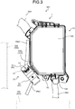
FIG. 3 is a plan view illustrating the electric connection box and the wire harness according to the embodiment as viewed vertically downward; -
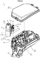
FIG. 4 is an exploded perspective view of the electric connection box with the side of a casing and the side of a terminal block separated; -
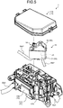
FIG. 5 is an exploded perspective view of the electric connection box with the side of the casing and the side of the terminal block separated, and is a front view of the side of a notch of an accommodation member; -
FIG. 6 is an exploded perspective view of the electric connection box with the side of the casing and the side of the terminal block separated, and is a front view of the side of a removable member of the terminal block; -
FIG. 7 is a perspective view illustrating an opened state of a second cover body in the terminal block; -
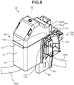
FIG. 8 is a perspective view of the opened state of the second cover body in the terminal block as viewed from another angle; -
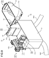
FIG. 9 is a perspective view illustrating the opened state of the second cover body in the terminal block; -
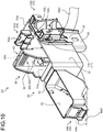
FIG. 10 is a perspective view of the opened state of the second cover body in the terminal block as viewed from another angle; -
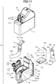
FIG. 11 is an exploded perspective view of the terminal block; -
FIG. 12 is an exploded perspective view of the terminal block viewed from another angle; and -
FIG. 13 is a cross-sectional view taken along line X-X ofFIG. 1 . - Hereinafter, embodiments of an electric connection box and a wire harness according to the present invention will be described in detail on the basis of the drawings. Note that the present invention is not limited by these embodiments.
- One of the embodiments of the electric connection box and the wire harness according to the present invention will be described on the basis of
FIGS. 1 to 13 . -
Reference numeral 1 inFIGS. 1 to 3 indicates an electric connection box of the present embodiment. Further, reference character WH inFIGS. 1 to 3 indicates a wire harness of the present embodiment including theelectric connection box 1. - The
electric connection box 1 of the present embodiment includes aninsulating casing 10 and at least one electric part (hereinafter, referred to as "internal electric parts" (not illustrated)) accommodated inside the casing 10 (FIGS. 1 to 3 ) . The internal electric parts are electrically connected to a plurality of electric wires (hereinafter, referred to as "internal electric wires") Wel inside thecasing 10. Theelectric connection box 1 further includes aterminal block 20 disposed outside the casing 10 (FIGS. 1 to 12 ). Theterminal block 20 is assembled into thecasing 10 on the outside of the casing 10 (FIGS. 1 to 6 ). Theterminal block 20 is provided with at least one electric part (hereinafter, referred to as an "external electric part") 30 electrically connected to at least one electric wire (hereinafter, referred to as an "external electric wire") We2 (FIGS. 9 to 12 ). Theelectric connection box 1 forms the wire harness WH together with the plurality of internal electric wires Wel drawn from the inside to the outside of thecasing 10 and at least one external electric wire We2 drawn from theterminal block 20. Note that the internal electric wire Wel in the drawings shows a plurality of internal electric wires bundled with exterior parts (a corrugated tube and the like), a protective tape, or the like. - Here, the internal electric part and the external
electric part 30 refer to an electronic part or a conductive part. The electronic part refers to, for example, a circuit protection part such as a relay or a fuse. Here, electronic devices such as a circuit board and an electronic control unit (so-called ECU) are also considered as a form of electronic parts. Further, the conductive part refers to a terminal fitting, a connector, a bus bar, or the like. - The internal electric part is electrically connected to a connection target via the internal electric wire Wel drawn to the outside of the
casing 10. The connection target refers to a power supply such as a secondary battery, a load such as an electric device (an actuator or the like), a sensor, or the like. In theelectric connection box 1 of this example, for example, a certain internal electric wire Wel is electrically connected to the power supply, and another internal electric wire Wel is electrically connected to the load, so that the power supply and the load are electrically connected via the internal electric part. - The
casing 10 in which the internal electric parts are accommodated is formed of an insulating material such as a synthetic resin. Thecasing 10 of this example includes acylindrical frame 10A that has both ends opened, a cover (hereinafter, referred to as a "first cover") 10B that closes one opening of theframe 10A, and a cover (hereinafter, referred to as a "second cover") 10C that closes the other opening of theframe 10A (FIGS. 1 to 6 ). In thecasing 10, each of thefirst cover 10B and thesecond cover 10C is detachably assembled into theframe 10A via a lock mechanism (for example, it locks the two parties with locking claws or the like in an assembled state). In addition, in thecasing 10, the internal electric parts are accommodated in an internal space surrounded by theframe 10A, thefirst cover 10B, and thesecond cover 10C in the assembled state, and the internal electric wires We1 electrically connected to the internal electric parts are drawn from the internal space to the outside. Note that, in thecasing 10, thefirst cover 10B and thesecond cover 10C are removable members that can be attached to and detached from theframe 10A. - Incidentally, in the
casing 10, theframe 10A has a function as an accommodation member for accommodating internal electric parts. In addition to thefirst cover 10B and thesecond cover 10C, thecasing 10 of this example includes aremovable member 10D that can be attached to and detached from theframe 10A (FIGS. 2 ,3 ,4 , and6 ). - For example, the
frame 10A illustrated here is provided with anotch 10A1 obtained by cutting a part of an outer wall (FIGS. 4 to 6 ). Thenotch 10A1 may cause the inside and the outside of theframe 10A to communicate with each other, and may be used when the internal electric parts inside theframe 10A are inspected, exchanged, or the like. Alternatively, thenotch 10A1 may form an opening of a wiring path of the electric wire, and may be used when the electric wire is disposed. In thecasing 10 illustrated here, theremovable member 10D is assembled into theframe 10A in order to close thenotch 10A1. That is, theremovable member 10D illustrated here is formed as a cover that can be attached to and detached from theframe 10A. In this example, thecasing 10 is mounted on a vehicle with each opening of theframe 10A oriented in a vertical direction. Therefore, theremovable member 10D of this example is formed as a cover (hereinafter, referred to as a "side cover") that closes thenotch 10A1 of theframe 10A and forms the outer wall of theframe 10A. Here, thenotch 10A1 is formed in a rectangular shape. Therefore, theremovable member 10D has a covermain body 10D1 with a rectangular plate shape that is matched with the shape of thenotch 10A1 (FIGS. 7 to 12 ). In theremovable member 10D, the outer wall of theframe 10A is formed by the covermain body 10D1. - A removable structure between the
frame 10A and theremovable member 10D as the side cover may be of any form. Here, a knownremovable structure 11 in the technical field in which theframe 10A and theremovable member 10D can be slid-fitted is mentioned as an example (FIG. 13 ). Theremovable structure 11 attaches/detaches theremovable member 10D to/from theframe 10A while sliding theremovable member 10D along a cylindrical axis direction of theframe 10A. Theremovable structure 11 includes aguide portion 11a formed on theframe 10A and a guidedportion 11b formed on one side of the covermain body 10D1 of theremovable member 10D. In theremovable structure 11, theremovable member 10D is assembled into theframe 10A by sliding and fitting the guidedportion 11b to theguide portion 11a along the cylindrical axis direction. Theguide portion 11a is formed in a circumferential portion along the cylindrical axis direction of thenotch 10A1 in theframe 10A. In addition, the guidedportion 11b is formed in a side portion along the cylindrical axis direction in an assembled state into theframe 10A, in the covermain body 10D1. Here, the circumferential portion itself of theframe 10A is used as theguide portion 11a, and the guidedportion 11b is formed in the side portion of the covermain body 10D1 so as to fit theguide portion 11a in a shape of a groove extending in the cylindrical axis direction. Theremovable structure 11 illustrated here includes two pairs ofguide portion 11a and guidedportion 11b. - The
casing 10 has a heldportion 12 that is attached to and held by a holdingportion 501 of an installation target 500 (FIG. 1 ). In thecasing 10 of this example, thefirst cover 10B is disposed vertically above theframe 10A, and thesecond cover 10C is disposed vertically below theframe 10A. For example, the heldportion 12 is provided in thesecond cover 10C and is attached to the holdingportion 501 of the vertically lower side in theinstallation target 500. Theinstallation target 500 illustrated here is a structure of a vehicle body in a vehicle such as an automobile. For example, theelectric connection box 1 is installed in an engine compartment of the vehicle body. - On the other hand, the
terminal block 20 may accommodate the externalelectric part 30 inside a casing (different from the casing 10), and may cause a holding member such as a so-called block to hold the externalelectric part 30. For example, the externalelectric part 30 illustrated here refers to an electric part for a predetermined work required at the predetermined work such as an emergency response or a maintenance work. Here, as the externalelectric part 30, a relief terminal for supplying electricity to another vehicle is mentioned as an example, and one external electric wire We2 drawn from theterminal block 20 is electrically connected to the power supply. Therefore, theterminal block 20 includes a holdingmember 40 that holds the externalelectric part 30 to be visually recognized by a worker, and aterminal cover 50 that covers the holdingmember 40 together with therelief terminal 30 from the outside (FIGS. 1 to 12 ). - In the
relief terminal 30 illustrated here, a rectangular and slice-shapedfirst connector 31 and a rectangular and slice-shapedsecond connector 32 intersect with each other (FIGS. 11 and12 ). Therelief terminal 30 of this example is formed as an L-shaped terminal fitting in which thefirst connector 31 and thesecond connector 32 are caused to be orthogonal to each other. In therelief terminal 30, for convenience, the side sandwiched between thefirst connector 31 and thesecond connector 32 is referred to as the inside, and the side opposite to this is referred to as the outside. Therefore, in therelief terminal 30, thefirst connector 31 and thesecond connector 32 have rectangular inner wall surfaces 31a and 32a on the inside and rectangular outer wall surfaces 31b and 32b on the outside, respectively. (FIGS. 11 and12 ). - At least one external electric wire We2 is electrically connected to the
relief terminal 30. In therelief terminal 30 of this example, one external electric wire We2 is electrically connected to each of thefirst connector 31 and thesecond connector 32. Here, a first terminal fitting 81 is physically and electrically connected to a terminal of one external electric wire We2, and a second terminal fitting 82 is physically and electrically connected to a terminal of the other external electric wire We2 (FIGS. 11 and12 ). In therelief terminal 30, one of the two external electric wires We2 is electrically connected to a power supply. - The first terminal fitting 81 of this example is an L-shaped terminal fitting in which slice-shaped first and
second connectors second connector 81b (FIGS. 11 and12 ). Therelief terminal 30 and the first terminal fitting 81 are physically and electrically connected by screwing and fixing thefirst connector 31 and thefirst connector 81a. Therefore, through-holes first connector 31 and thefirst connector 81a, respectively (FIGS. 11 and12 ). Further, the second terminal fitting 82 of this example is a terminal fitting in which slice-shaped first andsecond connectors second connector 82b (FIGS. 11 and12 ). Therelief terminal 30 and the second terminal fitting 82 are physically and electrically connected by screwing and fixing thesecond connector 32 and thefirst connector 82a. Therefore, through-holes second connector 32 and thefirst connector 82a, respectively (FIGS. 11 and12 ). A female screw (not illustrated) is attached to each male screw B. - Further, in the
relief terminal 30, thesecond connector 32 is sandwiched between clips (not illustrated) of a terminal of a booster cable, so that thesecond connector 32 is electrically connected to the booster cable. - The holding
member 40 and theterminal cover 50 are formed of an insulating material such as synthetic resin. Theterminal block 20 illustrated here is formed to accommodate therelief terminal 30 inside by the holdingmember 40 and theterminal cover 50 and to draw the external electric wire We2 from the inside to the outside. In theterminal block 20 of this example, therelief terminal 30, the first terminal fitting 81, and the second terminal fitting 82 are held by the holdingmember 40, and therelief terminal 30, the first terminal fitting 81, the second terminal fitting 82, and the holdingmember 40 are covered from the outside by theterminal cover 50. - The holding
member 40 has aterminal installation portion 41 into which theouter wall surface 31b of thefirst connector 31 is assembled, and aclip installation portion 42 in which theinner wall surface 32a of thesecond connector 32 is disposed to face theclip installation portion 42 and which is sandwiched between the clips of the booster cable together with the second connector 32 (FIG. 11 ). In the holdingmember 40, theterminal installation portion 41 is formed as a bottom portion of a firstconcave portion 40a. Further, in the holdingmember 40, theclip installation portion 42 is formed in a projection state as a part of a bottom portion of a secondconcave portion 40b (FIGS. 11 and12 ). The firstconcave portion 40a and the secondconcave portion 40b are formed so that the bottom portions thereof are orthogonal to each other. - The
terminal installation portion 41 of this example has aterminal installation surface 41a on which theouter wall surface 31b of thefirst connector 31 is mounted (FIG. 11 ). A stud bolt as the male screw B is assembled into theterminal installation portion 41 with the male screw portion Ba projected from theterminal installation surface 41a. For example, in theterminal installation portion 41, the male screw B is assembled from the side opposite to theterminal installation surface 41a. Therefore, theterminal installation portion 41 is provided with, for example, a locking claw that hooks on a square head portion of the assembled male screw B and locks the head portion. - The
clip installation portion 42 of this example is projected along aside wall 40a1 of the firstconcave portion 40a and toward the side of a free end of the male screw portion Ba, in a direction orthogonal to theterminal installation surface 41a of the terminal installation portion 41 (FIG. 11 ). Theclip installation portion 42 is formed in a plate shape having afirst wall surface 42a in which theinner wall surface 32a of thesecond connector 32 is disposed to face thefirst wall surface 42a, and asecond wall surface 42b which is provided along theside wall 40a1 of the firstconcave portion 40a (FIGS. 11 and12 ). The clips of the booster cable sandwich thesecond connector 32 and theclip installation portion 42 from the side of theouter wall surface 32b and the side of thesecond wall surface 42b. Further, a stud bolt as the male screw B is assembled into theclip installation portion 42 with the male screw portion Ba more projected than thefirst wall surface 42a (FIG. 12 ). - The
side wall 40a1 of the firstconcave portion 40a is provided with a through-hole 40c into which thefirst connector 31 is inserted from the side of thefirst wall surface 42a to the side of thesecond wall surface 42b of the clip installation portion 42 (FIG. 11 ). In the holdingmember 40, by inserting thefirst connector 31 into the through-hole 40c from the side of thefirst wall surface 42a, theouter wall surface 31b of thefirst connector 31 is mounted on theterminal installation surface 41a of theterminal installation portion 41. When thefirst connector 31 is inserted into the through-hole 40c, the male screw portion Ba of the male screw B assembled into theclip installation portion 42 in advance is inserted into the through-hole 32c of thesecond connector 32. In the holdingmember 40, the male screw B is assembled into theterminal installation portion 41 from the side opposite to theterminal installation surface 41a, so that the male screw portion Ba is inserted into the through-hole 31c of thefirst connector 31. In this way, therelief terminal 30 of this example is installed in the holdingmember 40. - Then, the first terminal fitting 81 and the second terminal fitting 82 are connected to the
relief terminal 30. For the first terminal fitting 81, thefirst connector 81a is mounted on theinner wall surface 31a of thefirst connector 31 while the male screw portion Ba of the male screw portion B assembled into theterminal installation portion 41 is inserted into the through-hole 81a1. In the holdingmember 40, thefirst connector 31 of therelief terminal 30 and thefirst connector 81a of the first terminal fitting 81 are screwed and fixed by screwing a female screw (not illustrated) into the male screw portion Ba. Further, for the second terminal fitting 82, thefirst connector 82a is disposed to face theouter wall surface 32b of thesecond connector 32 while the male screw portion Ba of the male screw portion B assembled into theclip installation portion 42 is inserted into the through-hole 82a1. In the holdingmember 40, thesecond connector 32 of therelief terminal 30 and thefirst connector 82a of the second terminal fitting 82 are screwed and fixed by screwing a female screw (not illustrated) into the male screw portion Ba. - The holding
member 40 has a thirdconcave portion 40d that is orthogonally connected to the firstconcave portion 40a (FIG. 11 ). In the holdingmember 40, thesecond connector 81b of the first terminal fitting 81 is disposed in the thirdconcave portion 40d, so that one external electric wire We2 is disposed along the thirdconcave portion 40d. Further, in the holdingmember 40, the second terminal fitting 82 is disposed in the secondconcave portion 40b, so that the other external electric wire We2 is disposed along the secondconcave portion 40b. - The holding
member 40 has a firstouter wall 43 and a secondouter wall 44 that are disposed to face each other at intervals, sandwich theterminal installation portion 41 and theclip installation portion 42, and form side walls of the facing arrangement state in the firstconcave portion 40a, the secondconcave portion 40b, and the thirdconcave portion 40d (FIGS. 11 and12 ). - The
terminal cover 50 is formed so as to cover the holdingmember 40 together with therelief terminal 30 and the first and secondterminal fittings clip installation portion 42. - The
terminal cover 50 of this example has a square cylindricalfirst cover body 51 with one end opened, and accommodates the holdingmember 40 from the opening (FIGS. 11 and12 ). At the other end of thefirst cover body 51 in a cylindrical axis direction, awall body 51b provided with a through-hole 51a is provided (FIGS. 9 and10 ). The through-hole 51a is a hole into which theclip installation portion 42 and thesecond connector 32 of therelief terminal 30 are inserted, and theclip installation portion 42 and thesecond connector 32 are more projected than thewall body 51b in a state where the holdingmember 40 is accommodated. - The
terminal cover 50 of this example has asecond cover body 52 that at least closes the through-hole 51a of thewall body 51b and covers theclip installation portion 42 and thesecond connector 32 more projected than thewall body 51b (FIGS. 1 to 12 ). Thesecond cover body 52 is formed in a square cylindrical shape with one end opened, and is attached to thefirst cover body 51 so as to be openable and closable. In theterminal cover 50 of this example, thefirst cover body 51 and thesecond cover body 52 are connected via aliving hinge 53, and thesecond cover body 52 is rotated with respect to thefirst cover body 51 about the living hinge 53 (FIGS. 7 to 10 ).FIGS. 1 to 8 illustrate a closed state of thesecond cover body 52 with respect to thefirst cover body 51.FIGS. 9 and10 illustrate an opened state of thesecond cover body 52 with respect to thefirst cover body 51. - The
terminal cover 50 of this example includes a holdingstructure 54 that holds thesecond cover body 52 in a closed state with respect to the first cover body 51 (FIGS. 1 to 12 ). The holdingstructure 54 includes afirst holding body 54a provided in thefirst cover body 51 and asecond holding body 54b provided in the second cover body 52 (FIGS. 7 to 12 ). Here, thefirst holding body 54a is provided in a projection state with respect to thewall body 51b, and thesecond holding body 54b is provided in a projection state with respect to the outer wall surface of thesecond cover body 52. Thefirst holding body 54a has a lockingportion 54a1 (FIG. 10 ). On the other hand, thesecond holding body 54b has a lockedportion 54b1 in which the relative movement toward the opened state at the position in the closed state is locked by the lockingportion 54a1 (FIG. 10 ). One of the lockingportion 54a1 and the lockedportion 54b1 of this example is formed as a claw portion, and the other is formed as a locking wall for hooking the claw portion. Here, the lockingportion 54a1 is formed as the claw portion, and the lockedportion 54b1 is formed as the locking wall. - As illustrated above, the
terminal block 20 is assembled into thecasing 10 on the outside of thecasing 10. In theelectric connection box 1, the holdingmember 40 of theterminal block 20 is integrated with one of the components forming thecasing 10 in order to improve the workability of assembling theterminal block 20 into thecasing 10. Specifically, the holdingmember 40 is formed as one part integrated with the removable member forming thecasing 10. The removable member illustrated here may be one of thefirst cover 10B, thesecond cover 10C, and the side cover (removable member 10D) illustrated above. In addition to these various covers, any removable member that can be attached to and detached from theframe 10A as the accommodation member may be used. In this example, theremovable member 10D as the side cover and the holdingmember 40 are formed as one part (FIGS. 7 to 13 ). - The
removable member 10D of this example has a connectingportion 10D2 projected from the outer wall surface of the covermain body 10D1, and is connected to the outer wall surface of the firstouter wall 43 of the holdingmember 40 via the connectingportion 10D2 (FIGS. 8 and10 to 13 ). In addition, thefirst cover body 51 of theterminal cover 50 of this example is provided with anotch 55 for avoiding the connectingportion 10D2 (FIGS. 8 ,10 ,12 , and13 ). - In the
electric connection box 1, theremovable member 10D as the side cover is assembled into theframe 10A before thefirst cover 10B is assembled into theframe 10A. Therefore, in theelectric connection box 1 of the present embodiment, theremovable member 10D is assembled into theframe 10A, so that the holdingmember 40 of theterminal block 20 is also assembled into theframe 10A. For example, in theterminal block 20, after therelief terminal 30, the first terminal fitting 81, and the second terminal fitting 82 are assembled into the holdingmember 40 in advance, theterminal cover 50 can be assembled into the holdingmember 40. Therefore, in theelectric connection box 1, theremovable member 10D is assembled into theframe 10A, so that theterminal block 20 including therelief terminal 30 and the like is assembled into theframe 10A. As described above, in theelectric connection box 1 of the present embodiment, even if an assembly process of theterminal block 20 into thecasing 10 is not separately provided, the assembly process is included in an assembly process of theremovable member 10D into theframe 10A, so that theremovable member 10D and theterminal block 20 can be assembled into theframe 10A at the same time. Therefore, in theelectric connection box 1, theterminal block 20 can be assembled into thecasing 10 with excellent assembly workability. Since the wire harness WH of the present embodiment includes theelectric connection box 1, it is possible to achieve a useful effect obtained by theelectric connection box 1. - Here, in the conventional electric connection box and wire harness, the relief terminal is accommodated in the casing together with the terminal cover as the internal electric part. For this reason, in the conventional electric connection box and wire harness, when the relief terminal is used, it is necessary to remove the first cover of the casing and remove the second cover body of the terminal cover from the first cover body. However, in the
electric connection box 1 and the wire harness WH of the present embodiment, therelief terminal 30 can be accessed only by opening thesecond cover body 52 of theterminal cover 50. Therefore, theelectric connection box 1 and the wire harness WH can also improve the workability at the time of an emergency response. - Further, in the
electric connection box 1 and the wire harness WH of the present embodiment, since therelief terminal 30 is disposed outside thecasing 10, the external electric wire We2 connected to therelief terminal 30 is also disposed outside thecasing 10. Therefore, if the volume of the internal space of thecasing 10 is the same, theelectric connection box 1 and the wire harness WH have an empty space corresponding to the external electric wire We2, so that the accommodation capacity of the parts for thecasing 10 can be improved. From another viewpoint, theelectric connection box 1 and the wire harness WH can reduce the volume of the internal space of thecasing 10 corresponding to the external electric wire We2, so that the size of thecasing 10 can be reduced. - Further, in the
electric connection box 1 and the wire harness WH of the present embodiment, thesecond cover body 52 of theterminal cover 50 is connected to thefirst cover body 51 via the livinghinge 53. Therefore, theelectric connection box 1 and the wire harness WH obtain a cost reduction effect by reducing the number of parts as compared with the conventional case. In addition, since theelectric connection box 1 and the wire harness WH do not require a work such as searching for a position of the removed second cover body as in the conventional case, it is possible to improve workability at the time of the emergency response. - Incidentally, in the
electric connection box 1, theterminal block 20 is preferably disposed in a state of being more projected than thecasing 10 to the side of avariable portion 502 according to an external input in an impact absorbing structure of a vehicle body which is the installation target 500 (FIG. 3 ). Thevariable portion 502 is a part of the vehicle body deformed when the external input of the predetermined magnitude or more is applied in order to absorb the impact caused by the external input. Therefore, in theelectric connection box 1 and the wire harness WH of the present embodiment, when thevariable portion 502 is deformed by the external input and comes into contact with theelectric connection box 1, thevariable portion 502 can be first hit against theterminal block 20, so that the internal electric parts and the like in thecasing 10 can be protected. In theelectric connection box 1 of this example, the externalelectric part 30 provided in theterminal block 20 is an electric part for the emergency response or the maintenance work. Therefore, even if a problem occurs in theterminal block 20, there is no urgent need for a repair work. - In the electric connection box and the wire harness according to the present embodiment, the removable member is assembled into the accommodation member, so that the holding member of the terminal block is also assembled into the accommodation member. For example, in the terminal block, the external electric part and the external electric wire can be assembled into the holding member in advance. Therefore, in the electric connection box and the wire harness, the removable member is assembled into the accommodation member, so that the terminal block including the external electric part and the like is assembled into the accommodation member. As described above, in the electric connection box and the wire harness according to the present embodiment, even if an assembly process of the terminal block into the casing is not separately provided, the assembly process is included in an assembly process of the removable member into the accommodation member, so that the removable member and the terminal block can be assembled into the accommodation member at the same time. Therefore, in the electric connection box and the wire harness, the terminal block can be assembled into the casing with excellent assembly workability.
- Although the invention has been described with respect to specific embodiments for a complete and clear disclosure, the appended claims are not to be thus limited but are to be construed as embodying all modifications and alternative constructions that may occur to one skilled in the art that fairly fall within the basic teaching herein set forth.
Claims (6)
- An electric connection box (1) comprising:an insulating casing (10);at least one internal electric part that is accommodated inside the casing (10) and is electrically connected to a plurality of internal electric wires (We1) drawn from an inside to an outside of the casing (10); anda terminal block (20) that is provided with at least one external electric part (30) electrically connected to at least one external electric wire (We2) and is assembled into the casing (10) outside the casing (10), whereinthe casing (10) includes an accommodation member (10A) that accommodates the internal electric part, and a removable member (10D) that is attached to and detached from the accommodation member (10A),the terminal block (20) includes a holding member (40) that holds the external electric part (30), andthe holding member (40) is formed as one part integrated with the removable member (10D).
- The electric connection box (1) according to claim 1, wherein
the removable member (10D) is a cover that is attached to and detached from the accommodation member (10A). - The electric connection box (1) according to claim 1, wherein
the removable member (10D) is a side cover that closes a notch in the accommodation member (10A) and forms an outer wall of the accommodation member (10A). - The electric connection box (1) according to claim 1, 2 or 3, wherein
the casing (10) has a held portion that is attached to and held by a holding portion of a vehicle body, and
the terminal block (20) is disposed in a state of being more projected than the casing (10) to a side of a variable portion according to an external input in an impact absorbing structure of the vehicle body. - The electric connection box (1) according to any one of claims 1 to 4, wherein
the external electric part (30) is a relief terminal that supplies electricity to another vehicle. - A wire harness (WH) comprising:an insulating casing (10);a plurality of internal electric wires (We1);at least one internal electric part that is accommodated inside the casing (10) and is electrically connected to the plurality of internal electric wires (We1) drawn from an inside to an outside of the casing (10);at least one external electric wire (We2); anda terminal block (20) that is provided with at least one external electric part (30) electrically connected to the at least one external electric wire (We2) and is assembled into the casing (10) outside the casing (10), whereinthe casing (10) includes an accommodation member (10A) that accommodates the internal electric part, and a removable member (10D) that is attached to and detached from the accommodation member (10A),the terminal block (20) includes a holding member (40) that holds the external electric part (30), andthe holding member (40) is formed as one part integrated with the removable member (10D).
Applications Claiming Priority (1)
| Application Number | Priority Date | Filing Date | Title |
|---|---|---|---|
| JP2019220115A JP7032001B2 (en) | 2019-12-05 | 2019-12-05 | Electrical junction box and wire harness |
Publications (2)
| Publication Number | Publication Date |
|---|---|
| EP3831665A1 true EP3831665A1 (en) | 2021-06-09 |
| EP3831665B1 EP3831665B1 (en) | 2024-02-21 |
Family
ID=73554262
Family Applications (1)
| Application Number | Title | Priority Date | Filing Date |
|---|---|---|---|
| EP20209387.8A Active EP3831665B1 (en) | 2019-12-05 | 2020-11-24 | Electric connection box and wire harness |
Country Status (4)
| Country | Link |
|---|---|
| US (1) | US11394187B2 (en) |
| EP (1) | EP3831665B1 (en) |
| JP (1) | JP7032001B2 (en) |
| CN (1) | CN112928715B (en) |
Families Citing this family (12)
| Publication number | Priority date | Publication date | Assignee | Title |
|---|---|---|---|---|
| JP7284135B2 (en) * | 2020-10-12 | 2023-05-30 | 矢崎総業株式会社 | Assembling structure of electrical junction box and method of assembling electrical junction box |
| US11855429B2 (en) * | 2021-07-29 | 2023-12-26 | Sumitomo Wiring Systems, Ltd. | Electric junction box assembly with removable cover |
| US12107404B2 (en) * | 2022-06-20 | 2024-10-01 | Sumitomo Wiring Systems, Ltd. | Junction box assembly having an ancillary box |
| JP7602518B2 (en) * | 2022-09-21 | 2024-12-18 | 矢崎総業株式会社 | Wire Harness |
| FR3141115A1 (en) * | 2022-10-21 | 2024-04-26 | Renault S.A.S | Interconnection box for a motor vehicle and vehicle comprising such a box. |
| JP7629434B2 (en) * | 2022-11-24 | 2025-02-13 | 矢崎総業株式会社 | Electrical Junction Box |
| JP7629435B2 (en) * | 2022-11-24 | 2025-02-13 | 矢崎総業株式会社 | Electrical Junction Box |
| JP7633986B2 (en) * | 2022-11-24 | 2025-02-20 | 矢崎総業株式会社 | Electrical Junction Box |
| JP7633984B2 (en) * | 2022-11-24 | 2025-02-20 | 矢崎総業株式会社 | Electrical Junction Box |
| JP7736661B2 (en) * | 2022-12-19 | 2025-09-09 | 矢崎総業株式会社 | Electrical junction box |
| JP2024147295A (en) * | 2023-04-03 | 2024-10-16 | 住友電装株式会社 | Terminal Blocks and Wire Harnesses |
| US12522154B2 (en) * | 2023-10-30 | 2026-01-13 | Fca Us Llc | Electric control unit (ECU) for a vehicle |
Citations (9)
| Publication number | Priority date | Publication date | Assignee | Title |
|---|---|---|---|---|
| US20050227542A1 (en) * | 2004-04-12 | 2005-10-13 | Autonetworks Technologies, Ltd. | Electrical connection box |
| JP2007330054A (en) * | 2006-06-08 | 2007-12-20 | Sumitomo Wiring Syst Ltd | Electrical junction box |
| JP2013034284A (en) * | 2011-08-01 | 2013-02-14 | Yazaki Corp | Electric connection box |
| JP2015079652A (en) * | 2013-10-17 | 2015-04-23 | 矢崎総業株式会社 | Relief terminal block, assembly of relief terminal block and frame |
| JP2015126543A (en) | 2013-12-25 | 2015-07-06 | 矢崎総業株式会社 | Electrical junction box |
| US20160020536A1 (en) * | 2014-07-18 | 2016-01-21 | Yazaki Corporation | Booster cable holding structure |
| US20160315458A1 (en) * | 2015-04-22 | 2016-10-27 | Yazaki Corporation | Electrical connection box and wire harness |
| US20170305370A1 (en) * | 2014-09-24 | 2017-10-26 | Sumitomo Wiring Systems, Ltd. | Electrical junction box |
| US20180309279A1 (en) * | 2017-04-25 | 2018-10-25 | Yazaki Corporation | Electrical connection box and wire harness |
Family Cites Families (9)
| Publication number | Priority date | Publication date | Assignee | Title |
|---|---|---|---|---|
| US6679708B1 (en) * | 2002-09-10 | 2004-01-20 | Sumitomo Wiring Systems, Ltd. | Vehicle junction box having power distribution center with terminal for jump-starting vehicle |
| JP2008123928A (en) * | 2006-11-15 | 2008-05-29 | Yazaki Corp | Terminal fitting and electric junction box provided with the terminal fitting |
| JP5074744B2 (en) * | 2006-11-15 | 2012-11-14 | 矢崎総業株式会社 | Electrical junction box |
| JP5836810B2 (en) * | 2012-01-13 | 2015-12-24 | 矢崎総業株式会社 | Screw connection block assembly structure of electrical junction box |
| JP6209558B2 (en) * | 2015-05-29 | 2017-10-04 | 矢崎総業株式会社 | Electrical junction box and wire harness |
| JP6499152B2 (en) * | 2016-12-27 | 2019-04-10 | 矢崎総業株式会社 | Electrical junction box and wire harness |
| JP6660914B2 (en) * | 2017-04-27 | 2020-03-11 | 矢崎総業株式会社 | Electrical junction box and wire harness |
| JP6644040B2 (en) * | 2017-10-02 | 2020-02-12 | 矢崎総業株式会社 | Waterproof structure of slide cover, electrical connection box and wire harness |
| JP6980488B2 (en) * | 2017-11-08 | 2021-12-15 | 矢崎総業株式会社 | Electrical junction box |
-
2019
- 2019-12-05 JP JP2019220115A patent/JP7032001B2/en active Active
-
2020
- 2020-11-24 US US17/102,466 patent/US11394187B2/en active Active
- 2020-11-24 EP EP20209387.8A patent/EP3831665B1/en active Active
- 2020-12-03 CN CN202011410909.6A patent/CN112928715B/en active Active
Patent Citations (9)
| Publication number | Priority date | Publication date | Assignee | Title |
|---|---|---|---|---|
| US20050227542A1 (en) * | 2004-04-12 | 2005-10-13 | Autonetworks Technologies, Ltd. | Electrical connection box |
| JP2007330054A (en) * | 2006-06-08 | 2007-12-20 | Sumitomo Wiring Syst Ltd | Electrical junction box |
| JP2013034284A (en) * | 2011-08-01 | 2013-02-14 | Yazaki Corp | Electric connection box |
| JP2015079652A (en) * | 2013-10-17 | 2015-04-23 | 矢崎総業株式会社 | Relief terminal block, assembly of relief terminal block and frame |
| JP2015126543A (en) | 2013-12-25 | 2015-07-06 | 矢崎総業株式会社 | Electrical junction box |
| US20160020536A1 (en) * | 2014-07-18 | 2016-01-21 | Yazaki Corporation | Booster cable holding structure |
| US20170305370A1 (en) * | 2014-09-24 | 2017-10-26 | Sumitomo Wiring Systems, Ltd. | Electrical junction box |
| US20160315458A1 (en) * | 2015-04-22 | 2016-10-27 | Yazaki Corporation | Electrical connection box and wire harness |
| US20180309279A1 (en) * | 2017-04-25 | 2018-10-25 | Yazaki Corporation | Electrical connection box and wire harness |
Also Published As
| Publication number | Publication date |
|---|---|
| CN112928715B (en) | 2023-03-14 |
| EP3831665B1 (en) | 2024-02-21 |
| CN112928715A (en) | 2021-06-08 |
| US11394187B2 (en) | 2022-07-19 |
| JP7032001B2 (en) | 2022-03-08 |
| JP2021090296A (en) | 2021-06-10 |
| US20210175697A1 (en) | 2021-06-10 |
Similar Documents
| Publication | Publication Date | Title |
|---|---|---|
| EP3831665B1 (en) | Electric connection box and wire harness | |
| EP3835135B1 (en) | Electric connection box and wire harness | |
| US10131297B1 (en) | Electric connection box and wire harness | |
| US20120043104A1 (en) | Electric junction box | |
| US9867299B2 (en) | Electrical connection box and wire harness | |
| JP6980488B2 (en) | Electrical junction box | |
| EP3745540B1 (en) | Connector and wire harness | |
| JP2016226249A (en) | Electrical junction box and wire harness | |
| CN108242790A (en) | Electrical junction box and wiring harness | |
| JP2002249003A (en) | Door checker harness | |
| US10374370B2 (en) | Electronic unit attaching structure | |
| JP4272495B2 (en) | Circuit board storage structure and electrical junction box | |
| JP7151360B2 (en) | electric junction box | |
| JP7100445B2 (en) | Housing, electrical junction box, and wire harness | |
| EP4059780B1 (en) | Electrical connection box | |
| JP7790960B2 (en) | Electrical junction boxes and wire harnesses | |
| US12262495B2 (en) | Electrical connection box | |
| US12344173B2 (en) | Sheath assembly and wire harness | |
| JP7602518B2 (en) | Wire Harness | |
| JP5381601B2 (en) | Electronic unit configuration module and electronic unit | |
| JP7467517B2 (en) | Connector assemblies, wire harnesses, and connector covers | |
| JP2009100576A (en) | Electrical junction box |
Legal Events
| Date | Code | Title | Description |
|---|---|---|---|
| PUAI | Public reference made under article 153(3) epc to a published international application that has entered the european phase |
Free format text: ORIGINAL CODE: 0009012 |
|
| STAA | Information on the status of an ep patent application or granted ep patent |
Free format text: STATUS: REQUEST FOR EXAMINATION WAS MADE |
|
| 17P | Request for examination filed |
Effective date: 20201124 |
|
| AK | Designated contracting states |
Kind code of ref document: A1 Designated state(s): AL AT BE BG CH CY CZ DE DK EE ES FI FR GB GR HR HU IE IS IT LI LT LU LV MC MK MT NL NO PL PT RO RS SE SI SK SM TR |
|
| RAP3 | Party data changed (applicant data changed or rights of an application transferred) |
Owner name: YAZAKI CORPORATION |
|
| GRAP | Despatch of communication of intention to grant a patent |
Free format text: ORIGINAL CODE: EPIDOSNIGR1 |
|
| STAA | Information on the status of an ep patent application or granted ep patent |
Free format text: STATUS: GRANT OF PATENT IS INTENDED |
|
| RIC1 | Information provided on ipc code assigned before grant |
Ipc: H05K 5/02 20060101ALI20230911BHEP Ipc: H02G 3/16 20060101ALI20230911BHEP Ipc: H02G 3/08 20060101ALI20230911BHEP Ipc: H02B 1/46 20060101ALI20230911BHEP Ipc: B60R 16/023 20060101AFI20230911BHEP |
|
| INTG | Intention to grant announced |
Effective date: 20231011 |
|
| GRAS | Grant fee paid |
Free format text: ORIGINAL CODE: EPIDOSNIGR3 |
|
| GRAA | (expected) grant |
Free format text: ORIGINAL CODE: 0009210 |
|
| STAA | Information on the status of an ep patent application or granted ep patent |
Free format text: STATUS: THE PATENT HAS BEEN GRANTED |
|
| AK | Designated contracting states |
Kind code of ref document: B1 Designated state(s): AL AT BE BG CH CY CZ DE DK EE ES FI FR GB GR HR HU IE IS IT LI LT LU LV MC MK MT NL NO PL PT RO RS SE SI SK SM TR |
|
| REG | Reference to a national code |
Ref country code: GB Ref legal event code: FG4D |
|
| REG | Reference to a national code |
Ref country code: CH Ref legal event code: EP |
|
| REG | Reference to a national code |
Ref country code: DE Ref legal event code: R096 Ref document number: 602020025975 Country of ref document: DE |
|
| REG | Reference to a national code |
Ref country code: IE Ref legal event code: FG4D |
|
| REG | Reference to a national code |
Ref country code: LT Ref legal event code: MG9D |
|
| REG | Reference to a national code |
Ref country code: NL Ref legal event code: MP Effective date: 20240221 |
|
| PG25 | Lapsed in a contracting state [announced via postgrant information from national office to epo] |
Ref country code: IS Free format text: LAPSE BECAUSE OF FAILURE TO SUBMIT A TRANSLATION OF THE DESCRIPTION OR TO PAY THE FEE WITHIN THE PRESCRIBED TIME-LIMIT Effective date: 20240621 |
|
| PG25 | Lapsed in a contracting state [announced via postgrant information from national office to epo] |
Ref country code: LT Free format text: LAPSE BECAUSE OF FAILURE TO SUBMIT A TRANSLATION OF THE DESCRIPTION OR TO PAY THE FEE WITHIN THE PRESCRIBED TIME-LIMIT Effective date: 20240221 |
|
| PG25 | Lapsed in a contracting state [announced via postgrant information from national office to epo] |
Ref country code: GR Free format text: LAPSE BECAUSE OF FAILURE TO SUBMIT A TRANSLATION OF THE DESCRIPTION OR TO PAY THE FEE WITHIN THE PRESCRIBED TIME-LIMIT Effective date: 20240522 |
|
| REG | Reference to a national code |
Ref country code: AT Ref legal event code: MK05 Ref document number: 1658879 Country of ref document: AT Kind code of ref document: T Effective date: 20240221 |
|
| PG25 | Lapsed in a contracting state [announced via postgrant information from national office to epo] |
Ref country code: HR Free format text: LAPSE BECAUSE OF FAILURE TO SUBMIT A TRANSLATION OF THE DESCRIPTION OR TO PAY THE FEE WITHIN THE PRESCRIBED TIME-LIMIT Effective date: 20240221 Ref country code: NL Free format text: LAPSE BECAUSE OF FAILURE TO SUBMIT A TRANSLATION OF THE DESCRIPTION OR TO PAY THE FEE WITHIN THE PRESCRIBED TIME-LIMIT Effective date: 20240221 Ref country code: RS Free format text: LAPSE BECAUSE OF FAILURE TO SUBMIT A TRANSLATION OF THE DESCRIPTION OR TO PAY THE FEE WITHIN THE PRESCRIBED TIME-LIMIT Effective date: 20240521 |
|
| PG25 | Lapsed in a contracting state [announced via postgrant information from national office to epo] |
Ref country code: ES Free format text: LAPSE BECAUSE OF FAILURE TO SUBMIT A TRANSLATION OF THE DESCRIPTION OR TO PAY THE FEE WITHIN THE PRESCRIBED TIME-LIMIT Effective date: 20240221 |
|
| PG25 | Lapsed in a contracting state [announced via postgrant information from national office to epo] |
Ref country code: AT Free format text: LAPSE BECAUSE OF FAILURE TO SUBMIT A TRANSLATION OF THE DESCRIPTION OR TO PAY THE FEE WITHIN THE PRESCRIBED TIME-LIMIT Effective date: 20240221 |
|
| PG25 | Lapsed in a contracting state [announced via postgrant information from national office to epo] |
Ref country code: RS Free format text: LAPSE BECAUSE OF FAILURE TO SUBMIT A TRANSLATION OF THE DESCRIPTION OR TO PAY THE FEE WITHIN THE PRESCRIBED TIME-LIMIT Effective date: 20240521 Ref country code: NO Free format text: LAPSE BECAUSE OF FAILURE TO SUBMIT A TRANSLATION OF THE DESCRIPTION OR TO PAY THE FEE WITHIN THE PRESCRIBED TIME-LIMIT Effective date: 20240521 Ref country code: NL Free format text: LAPSE BECAUSE OF FAILURE TO SUBMIT A TRANSLATION OF THE DESCRIPTION OR TO PAY THE FEE WITHIN THE PRESCRIBED TIME-LIMIT Effective date: 20240221 Ref country code: LT Free format text: LAPSE BECAUSE OF FAILURE TO SUBMIT A TRANSLATION OF THE DESCRIPTION OR TO PAY THE FEE WITHIN THE PRESCRIBED TIME-LIMIT Effective date: 20240221 Ref country code: IS Free format text: LAPSE BECAUSE OF FAILURE TO SUBMIT A TRANSLATION OF THE DESCRIPTION OR TO PAY THE FEE WITHIN THE PRESCRIBED TIME-LIMIT Effective date: 20240621 Ref country code: HR Free format text: LAPSE BECAUSE OF FAILURE TO SUBMIT A TRANSLATION OF THE DESCRIPTION OR TO PAY THE FEE WITHIN THE PRESCRIBED TIME-LIMIT Effective date: 20240221 Ref country code: GR Free format text: LAPSE BECAUSE OF FAILURE TO SUBMIT A TRANSLATION OF THE DESCRIPTION OR TO PAY THE FEE WITHIN THE PRESCRIBED TIME-LIMIT Effective date: 20240522 Ref country code: FI Free format text: LAPSE BECAUSE OF FAILURE TO SUBMIT A TRANSLATION OF THE DESCRIPTION OR TO PAY THE FEE WITHIN THE PRESCRIBED TIME-LIMIT Effective date: 20240221 Ref country code: ES Free format text: LAPSE BECAUSE OF FAILURE TO SUBMIT A TRANSLATION OF THE DESCRIPTION OR TO PAY THE FEE WITHIN THE PRESCRIBED TIME-LIMIT Effective date: 20240221 Ref country code: BG Free format text: LAPSE BECAUSE OF FAILURE TO SUBMIT A TRANSLATION OF THE DESCRIPTION OR TO PAY THE FEE WITHIN THE PRESCRIBED TIME-LIMIT Effective date: 20240221 Ref country code: AT Free format text: LAPSE BECAUSE OF FAILURE TO SUBMIT A TRANSLATION OF THE DESCRIPTION OR TO PAY THE FEE WITHIN THE PRESCRIBED TIME-LIMIT Effective date: 20240221 |
|
| PG25 | Lapsed in a contracting state [announced via postgrant information from national office to epo] |
Ref country code: PL Free format text: LAPSE BECAUSE OF FAILURE TO SUBMIT A TRANSLATION OF THE DESCRIPTION OR TO PAY THE FEE WITHIN THE PRESCRIBED TIME-LIMIT Effective date: 20240221 Ref country code: PT Free format text: LAPSE BECAUSE OF FAILURE TO SUBMIT A TRANSLATION OF THE DESCRIPTION OR TO PAY THE FEE WITHIN THE PRESCRIBED TIME-LIMIT Effective date: 20240621 |
|
| PG25 | Lapsed in a contracting state [announced via postgrant information from national office to epo] |
Ref country code: SE Free format text: LAPSE BECAUSE OF FAILURE TO SUBMIT A TRANSLATION OF THE DESCRIPTION OR TO PAY THE FEE WITHIN THE PRESCRIBED TIME-LIMIT Effective date: 20240221 Ref country code: PT Free format text: LAPSE BECAUSE OF FAILURE TO SUBMIT A TRANSLATION OF THE DESCRIPTION OR TO PAY THE FEE WITHIN THE PRESCRIBED TIME-LIMIT Effective date: 20240621 Ref country code: PL Free format text: LAPSE BECAUSE OF FAILURE TO SUBMIT A TRANSLATION OF THE DESCRIPTION OR TO PAY THE FEE WITHIN THE PRESCRIBED TIME-LIMIT Effective date: 20240221 Ref country code: LV Free format text: LAPSE BECAUSE OF FAILURE TO SUBMIT A TRANSLATION OF THE DESCRIPTION OR TO PAY THE FEE WITHIN THE PRESCRIBED TIME-LIMIT Effective date: 20240221 |
|
| PG25 | Lapsed in a contracting state [announced via postgrant information from national office to epo] |
Ref country code: DK Free format text: LAPSE BECAUSE OF FAILURE TO SUBMIT A TRANSLATION OF THE DESCRIPTION OR TO PAY THE FEE WITHIN THE PRESCRIBED TIME-LIMIT Effective date: 20240221 |
|
| PG25 | Lapsed in a contracting state [announced via postgrant information from national office to epo] |
Ref country code: SM Free format text: LAPSE BECAUSE OF FAILURE TO SUBMIT A TRANSLATION OF THE DESCRIPTION OR TO PAY THE FEE WITHIN THE PRESCRIBED TIME-LIMIT Effective date: 20240221 |
|
| PG25 | Lapsed in a contracting state [announced via postgrant information from national office to epo] |
Ref country code: CZ Free format text: LAPSE BECAUSE OF FAILURE TO SUBMIT A TRANSLATION OF THE DESCRIPTION OR TO PAY THE FEE WITHIN THE PRESCRIBED TIME-LIMIT Effective date: 20240221 Ref country code: EE Free format text: LAPSE BECAUSE OF FAILURE TO SUBMIT A TRANSLATION OF THE DESCRIPTION OR TO PAY THE FEE WITHIN THE PRESCRIBED TIME-LIMIT Effective date: 20240221 |
|
| PG25 | Lapsed in a contracting state [announced via postgrant information from national office to epo] |
Ref country code: SK Free format text: LAPSE BECAUSE OF FAILURE TO SUBMIT A TRANSLATION OF THE DESCRIPTION OR TO PAY THE FEE WITHIN THE PRESCRIBED TIME-LIMIT Effective date: 20240221 |
|
| PG25 | Lapsed in a contracting state [announced via postgrant information from national office to epo] |
Ref country code: SM Free format text: LAPSE BECAUSE OF FAILURE TO SUBMIT A TRANSLATION OF THE DESCRIPTION OR TO PAY THE FEE WITHIN THE PRESCRIBED TIME-LIMIT Effective date: 20240221 Ref country code: SK Free format text: LAPSE BECAUSE OF FAILURE TO SUBMIT A TRANSLATION OF THE DESCRIPTION OR TO PAY THE FEE WITHIN THE PRESCRIBED TIME-LIMIT Effective date: 20240221 Ref country code: RO Free format text: LAPSE BECAUSE OF FAILURE TO SUBMIT A TRANSLATION OF THE DESCRIPTION OR TO PAY THE FEE WITHIN THE PRESCRIBED TIME-LIMIT Effective date: 20240221 Ref country code: EE Free format text: LAPSE BECAUSE OF FAILURE TO SUBMIT A TRANSLATION OF THE DESCRIPTION OR TO PAY THE FEE WITHIN THE PRESCRIBED TIME-LIMIT Effective date: 20240221 Ref country code: DK Free format text: LAPSE BECAUSE OF FAILURE TO SUBMIT A TRANSLATION OF THE DESCRIPTION OR TO PAY THE FEE WITHIN THE PRESCRIBED TIME-LIMIT Effective date: 20240221 Ref country code: CZ Free format text: LAPSE BECAUSE OF FAILURE TO SUBMIT A TRANSLATION OF THE DESCRIPTION OR TO PAY THE FEE WITHIN THE PRESCRIBED TIME-LIMIT Effective date: 20240221 |
|
| REG | Reference to a national code |
Ref country code: DE Ref legal event code: R097 Ref document number: 602020025975 Country of ref document: DE |
|
| PG25 | Lapsed in a contracting state [announced via postgrant information from national office to epo] |
Ref country code: IT Free format text: LAPSE BECAUSE OF FAILURE TO SUBMIT A TRANSLATION OF THE DESCRIPTION OR TO PAY THE FEE WITHIN THE PRESCRIBED TIME-LIMIT Effective date: 20240221 |
|
| PLBE | No opposition filed within time limit |
Free format text: ORIGINAL CODE: 0009261 |
|
| STAA | Information on the status of an ep patent application or granted ep patent |
Free format text: STATUS: NO OPPOSITION FILED WITHIN TIME LIMIT |
|
| PG25 | Lapsed in a contracting state [announced via postgrant information from national office to epo] |
Ref country code: IT Free format text: LAPSE BECAUSE OF FAILURE TO SUBMIT A TRANSLATION OF THE DESCRIPTION OR TO PAY THE FEE WITHIN THE PRESCRIBED TIME-LIMIT Effective date: 20240221 |
|
| 26N | No opposition filed |
Effective date: 20241122 |
|
| PG25 | Lapsed in a contracting state [announced via postgrant information from national office to epo] |
Ref country code: SI Free format text: LAPSE BECAUSE OF FAILURE TO SUBMIT A TRANSLATION OF THE DESCRIPTION OR TO PAY THE FEE WITHIN THE PRESCRIBED TIME-LIMIT Effective date: 20240221 |
|
| REG | Reference to a national code |
Ref country code: CH Ref legal event code: PL |
|
| PG25 | Lapsed in a contracting state [announced via postgrant information from national office to epo] |
Ref country code: MC Free format text: LAPSE BECAUSE OF FAILURE TO SUBMIT A TRANSLATION OF THE DESCRIPTION OR TO PAY THE FEE WITHIN THE PRESCRIBED TIME-LIMIT Effective date: 20240221 |
|
| PG25 | Lapsed in a contracting state [announced via postgrant information from national office to epo] |
Ref country code: LU Free format text: LAPSE BECAUSE OF NON-PAYMENT OF DUE FEES Effective date: 20241124 |
|
| REG | Reference to a national code |
Ref country code: CH Ref legal event code: PL |
|
| GBPC | Gb: european patent ceased through non-payment of renewal fee |
Effective date: 20241124 |
|
| PG25 | Lapsed in a contracting state [announced via postgrant information from national office to epo] |
Ref country code: CH Free format text: LAPSE BECAUSE OF NON-PAYMENT OF DUE FEES Effective date: 20241130 |
|
| REG | Reference to a national code |
Ref country code: BE Ref legal event code: MM Effective date: 20241130 |
|
| PG25 | Lapsed in a contracting state [announced via postgrant information from national office to epo] |
Ref country code: GB Free format text: LAPSE BECAUSE OF NON-PAYMENT OF DUE FEES Effective date: 20241124 Ref country code: BE Free format text: LAPSE BECAUSE OF NON-PAYMENT OF DUE FEES Effective date: 20241130 |
|
| PG25 | Lapsed in a contracting state [announced via postgrant information from national office to epo] |
Ref country code: FR Free format text: LAPSE BECAUSE OF NON-PAYMENT OF DUE FEES Effective date: 20241130 |
|
| PG25 | Lapsed in a contracting state [announced via postgrant information from national office to epo] |
Ref country code: IE Free format text: LAPSE BECAUSE OF NON-PAYMENT OF DUE FEES Effective date: 20241124 |
|
| PGFP | Annual fee paid to national office [announced via postgrant information from national office to epo] |
Ref country code: DE Payment date: 20250930 Year of fee payment: 6 |
|
| PG25 | Lapsed in a contracting state [announced via postgrant information from national office to epo] |
Ref country code: HU Free format text: LAPSE BECAUSE OF FAILURE TO SUBMIT A TRANSLATION OF THE DESCRIPTION OR TO PAY THE FEE WITHIN THE PRESCRIBED TIME-LIMIT; INVALID AB INITIO Effective date: 20201124 |
|
| PG25 | Lapsed in a contracting state [announced via postgrant information from national office to epo] |
Ref country code: CY Free format text: LAPSE BECAUSE OF FAILURE TO SUBMIT A TRANSLATION OF THE DESCRIPTION OR TO PAY THE FEE WITHIN THE PRESCRIBED TIME-LIMIT; INVALID AB INITIO Effective date: 20201124 |