EP3831656A1 - A vehicle system to facilitate cosmetic care - Google Patents
A vehicle system to facilitate cosmetic care Download PDFInfo
- Publication number
- EP3831656A1 EP3831656A1 EP19214237.0A EP19214237A EP3831656A1 EP 3831656 A1 EP3831656 A1 EP 3831656A1 EP 19214237 A EP19214237 A EP 19214237A EP 3831656 A1 EP3831656 A1 EP 3831656A1
- Authority
- EP
- European Patent Office
- Prior art keywords
- vehicle
- state
- holding device
- compartment
- holding
- Prior art date
- Legal status (The legal status is an assumption and is not a legal conclusion. Google has not performed a legal analysis and makes no representation as to the accuracy of the status listed.)
- Granted
Links
Images





Classifications
-
- B—PERFORMING OPERATIONS; TRANSPORTING
- B60—VEHICLES IN GENERAL
- B60H—ARRANGEMENTS OF HEATING, COOLING, VENTILATING OR OTHER AIR-TREATING DEVICES SPECIALLY ADAPTED FOR PASSENGER OR GOODS SPACES OF VEHICLES
- B60H1/00—Heating, cooling or ventilating devices
- B60H1/00642—Control systems or circuits; Control members or indication devices for heating, cooling or ventilating devices
- B60H1/00735—Control systems or circuits characterised by their input, i.e. by the detection, measurement or calculation of particular conditions, e.g. signal treatment, dynamic models
-
- B—PERFORMING OPERATIONS; TRANSPORTING
- B60—VEHICLES IN GENERAL
- B60K—ARRANGEMENT OR MOUNTING OF PROPULSION UNITS OR OF TRANSMISSIONS IN VEHICLES; ARRANGEMENT OR MOUNTING OF PLURAL DIVERSE PRIME-MOVERS IN VEHICLES; AUXILIARY DRIVES FOR VEHICLES; INSTRUMENTATION OR DASHBOARDS FOR VEHICLES; ARRANGEMENTS IN CONNECTION WITH COOLING, AIR INTAKE, GAS EXHAUST OR FUEL SUPPLY OF PROPULSION UNITS IN VEHICLES
- B60K35/00—Instruments specially adapted for vehicles; Arrangement of instruments in or on vehicles
- B60K35/10—Input arrangements, i.e. from user to vehicle, associated with vehicle functions or specially adapted therefor
-
- B—PERFORMING OPERATIONS; TRANSPORTING
- B60—VEHICLES IN GENERAL
- B60K—ARRANGEMENT OR MOUNTING OF PROPULSION UNITS OR OF TRANSMISSIONS IN VEHICLES; ARRANGEMENT OR MOUNTING OF PLURAL DIVERSE PRIME-MOVERS IN VEHICLES; AUXILIARY DRIVES FOR VEHICLES; INSTRUMENTATION OR DASHBOARDS FOR VEHICLES; ARRANGEMENTS IN CONNECTION WITH COOLING, AIR INTAKE, GAS EXHAUST OR FUEL SUPPLY OF PROPULSION UNITS IN VEHICLES
- B60K35/00—Instruments specially adapted for vehicles; Arrangement of instruments in or on vehicles
- B60K35/20—Output arrangements, i.e. from vehicle to user, associated with vehicle functions or specially adapted therefor
- B60K35/21—Output arrangements, i.e. from vehicle to user, associated with vehicle functions or specially adapted therefor using visual output, e.g. blinking lights or matrix displays
- B60K35/22—Display screens
-
- B—PERFORMING OPERATIONS; TRANSPORTING
- B60—VEHICLES IN GENERAL
- B60K—ARRANGEMENT OR MOUNTING OF PROPULSION UNITS OR OF TRANSMISSIONS IN VEHICLES; ARRANGEMENT OR MOUNTING OF PLURAL DIVERSE PRIME-MOVERS IN VEHICLES; AUXILIARY DRIVES FOR VEHICLES; INSTRUMENTATION OR DASHBOARDS FOR VEHICLES; ARRANGEMENTS IN CONNECTION WITH COOLING, AIR INTAKE, GAS EXHAUST OR FUEL SUPPLY OF PROPULSION UNITS IN VEHICLES
- B60K35/00—Instruments specially adapted for vehicles; Arrangement of instruments in or on vehicles
- B60K35/20—Output arrangements, i.e. from vehicle to user, associated with vehicle functions or specially adapted therefor
- B60K35/28—Output arrangements, i.e. from vehicle to user, associated with vehicle functions or specially adapted therefor characterised by the type of the output information, e.g. video entertainment or vehicle dynamics information; characterised by the purpose of the output information, e.g. for attracting the attention of the driver
-
- B—PERFORMING OPERATIONS; TRANSPORTING
- B60—VEHICLES IN GENERAL
- B60K—ARRANGEMENT OR MOUNTING OF PROPULSION UNITS OR OF TRANSMISSIONS IN VEHICLES; ARRANGEMENT OR MOUNTING OF PLURAL DIVERSE PRIME-MOVERS IN VEHICLES; AUXILIARY DRIVES FOR VEHICLES; INSTRUMENTATION OR DASHBOARDS FOR VEHICLES; ARRANGEMENTS IN CONNECTION WITH COOLING, AIR INTAKE, GAS EXHAUST OR FUEL SUPPLY OF PROPULSION UNITS IN VEHICLES
- B60K35/00—Instruments specially adapted for vehicles; Arrangement of instruments in or on vehicles
- B60K35/20—Output arrangements, i.e. from vehicle to user, associated with vehicle functions or specially adapted therefor
- B60K35/29—Instruments characterised by the way in which information is handled, e.g. showing information on plural displays or prioritising information according to driving conditions
-
- B—PERFORMING OPERATIONS; TRANSPORTING
- B60—VEHICLES IN GENERAL
- B60K—ARRANGEMENT OR MOUNTING OF PROPULSION UNITS OR OF TRANSMISSIONS IN VEHICLES; ARRANGEMENT OR MOUNTING OF PLURAL DIVERSE PRIME-MOVERS IN VEHICLES; AUXILIARY DRIVES FOR VEHICLES; INSTRUMENTATION OR DASHBOARDS FOR VEHICLES; ARRANGEMENTS IN CONNECTION WITH COOLING, AIR INTAKE, GAS EXHAUST OR FUEL SUPPLY OF PROPULSION UNITS IN VEHICLES
- B60K35/00—Instruments specially adapted for vehicles; Arrangement of instruments in or on vehicles
- B60K35/50—Instruments characterised by their means of attachment to or integration in the vehicle
- B60K35/53—Movable instruments, e.g. slidable
-
- B—PERFORMING OPERATIONS; TRANSPORTING
- B60—VEHICLES IN GENERAL
- B60K—ARRANGEMENT OR MOUNTING OF PROPULSION UNITS OR OF TRANSMISSIONS IN VEHICLES; ARRANGEMENT OR MOUNTING OF PLURAL DIVERSE PRIME-MOVERS IN VEHICLES; AUXILIARY DRIVES FOR VEHICLES; INSTRUMENTATION OR DASHBOARDS FOR VEHICLES; ARRANGEMENTS IN CONNECTION WITH COOLING, AIR INTAKE, GAS EXHAUST OR FUEL SUPPLY OF PROPULSION UNITS IN VEHICLES
- B60K35/00—Instruments specially adapted for vehicles; Arrangement of instruments in or on vehicles
- B60K35/60—Instruments characterised by their location or relative disposition in or on vehicles
-
- B—PERFORMING OPERATIONS; TRANSPORTING
- B60—VEHICLES IN GENERAL
- B60K—ARRANGEMENT OR MOUNTING OF PROPULSION UNITS OR OF TRANSMISSIONS IN VEHICLES; ARRANGEMENT OR MOUNTING OF PLURAL DIVERSE PRIME-MOVERS IN VEHICLES; AUXILIARY DRIVES FOR VEHICLES; INSTRUMENTATION OR DASHBOARDS FOR VEHICLES; ARRANGEMENTS IN CONNECTION WITH COOLING, AIR INTAKE, GAS EXHAUST OR FUEL SUPPLY OF PROPULSION UNITS IN VEHICLES
- B60K35/00—Instruments specially adapted for vehicles; Arrangement of instruments in or on vehicles
- B60K35/80—Arrangements for controlling instruments
-
- B—PERFORMING OPERATIONS; TRANSPORTING
- B60—VEHICLES IN GENERAL
- B60Q—ARRANGEMENT OF SIGNALLING OR LIGHTING DEVICES, THE MOUNTING OR SUPPORTING THEREOF OR CIRCUITS THEREFOR, FOR VEHICLES IN GENERAL
- B60Q3/00—Arrangement of lighting devices for vehicle interiors; Lighting devices specially adapted for vehicle interiors
- B60Q3/20—Arrangement of lighting devices for vehicle interiors; Lighting devices specially adapted for vehicle interiors for lighting specific fittings of passenger or driving compartments; mounted on specific fittings of passenger or driving compartments
-
- B—PERFORMING OPERATIONS; TRANSPORTING
- B60—VEHICLES IN GENERAL
- B60Q—ARRANGEMENT OF SIGNALLING OR LIGHTING DEVICES, THE MOUNTING OR SUPPORTING THEREOF OR CIRCUITS THEREFOR, FOR VEHICLES IN GENERAL
- B60Q3/00—Arrangement of lighting devices for vehicle interiors; Lighting devices specially adapted for vehicle interiors
- B60Q3/20—Arrangement of lighting devices for vehicle interiors; Lighting devices specially adapted for vehicle interiors for lighting specific fittings of passenger or driving compartments; mounted on specific fittings of passenger or driving compartments
- B60Q3/252—Sun visors
-
- B—PERFORMING OPERATIONS; TRANSPORTING
- B60—VEHICLES IN GENERAL
- B60Q—ARRANGEMENT OF SIGNALLING OR LIGHTING DEVICES, THE MOUNTING OR SUPPORTING THEREOF OR CIRCUITS THEREFOR, FOR VEHICLES IN GENERAL
- B60Q3/00—Arrangement of lighting devices for vehicle interiors; Lighting devices specially adapted for vehicle interiors
- B60Q3/80—Circuits; Control arrangements
-
- B—PERFORMING OPERATIONS; TRANSPORTING
- B60—VEHICLES IN GENERAL
- B60R—VEHICLES, VEHICLE FITTINGS, OR VEHICLE PARTS, NOT OTHERWISE PROVIDED FOR
- B60R7/00—Stowing or holding appliances inside vehicle primarily intended for personal property smaller than suit-cases, e.g. travelling articles, or maps
- B60R7/04—Stowing or holding appliances inside vehicle primarily intended for personal property smaller than suit-cases, e.g. travelling articles, or maps in driver or passenger space, e.g. using racks
-
- B—PERFORMING OPERATIONS; TRANSPORTING
- B60—VEHICLES IN GENERAL
- B60H—ARRANGEMENTS OF HEATING, COOLING, VENTILATING OR OTHER AIR-TREATING DEVICES SPECIALLY ADAPTED FOR PASSENGER OR GOODS SPACES OF VEHICLES
- B60H1/00—Heating, cooling or ventilating devices
- B60H1/00642—Control systems or circuits; Control members or indication devices for heating, cooling or ventilating devices
- B60H1/00814—Control systems or circuits characterised by their output, for controlling particular components of the heating, cooling or ventilating installation
- B60H1/00821—Control systems or circuits characterised by their output, for controlling particular components of the heating, cooling or ventilating installation the components being ventilating, air admitting or air distributing devices
-
- B—PERFORMING OPERATIONS; TRANSPORTING
- B60—VEHICLES IN GENERAL
- B60K—ARRANGEMENT OR MOUNTING OF PROPULSION UNITS OR OF TRANSMISSIONS IN VEHICLES; ARRANGEMENT OR MOUNTING OF PLURAL DIVERSE PRIME-MOVERS IN VEHICLES; AUXILIARY DRIVES FOR VEHICLES; INSTRUMENTATION OR DASHBOARDS FOR VEHICLES; ARRANGEMENTS IN CONNECTION WITH COOLING, AIR INTAKE, GAS EXHAUST OR FUEL SUPPLY OF PROPULSION UNITS IN VEHICLES
- B60K2360/00—Indexing scheme associated with groups B60K35/00 or B60K37/00 relating to details of instruments or dashboards
- B60K2360/16—Type of output information
- B60K2360/175—Autonomous driving
-
- B—PERFORMING OPERATIONS; TRANSPORTING
- B60—VEHICLES IN GENERAL
- B60K—ARRANGEMENT OR MOUNTING OF PROPULSION UNITS OR OF TRANSMISSIONS IN VEHICLES; ARRANGEMENT OR MOUNTING OF PLURAL DIVERSE PRIME-MOVERS IN VEHICLES; AUXILIARY DRIVES FOR VEHICLES; INSTRUMENTATION OR DASHBOARDS FOR VEHICLES; ARRANGEMENTS IN CONNECTION WITH COOLING, AIR INTAKE, GAS EXHAUST OR FUEL SUPPLY OF PROPULSION UNITS IN VEHICLES
- B60K2360/00—Indexing scheme associated with groups B60K35/00 or B60K37/00 relating to details of instruments or dashboards
- B60K2360/18—Information management
- B60K2360/195—Blocking or enabling display functions
-
- B—PERFORMING OPERATIONS; TRANSPORTING
- B60—VEHICLES IN GENERAL
- B60K—ARRANGEMENT OR MOUNTING OF PROPULSION UNITS OR OF TRANSMISSIONS IN VEHICLES; ARRANGEMENT OR MOUNTING OF PLURAL DIVERSE PRIME-MOVERS IN VEHICLES; AUXILIARY DRIVES FOR VEHICLES; INSTRUMENTATION OR DASHBOARDS FOR VEHICLES; ARRANGEMENTS IN CONNECTION WITH COOLING, AIR INTAKE, GAS EXHAUST OR FUEL SUPPLY OF PROPULSION UNITS IN VEHICLES
- B60K2360/00—Indexing scheme associated with groups B60K35/00 or B60K37/00 relating to details of instruments or dashboards
- B60K2360/77—Instrument locations other than the dashboard
- B60K2360/791—Instrument locations other than the dashboard on or in the transmission tunnel or parking brake lever
Definitions
- the present disclosure relates to a vehicle system comprising a control unit, a vehicle compartment holding device for holding a removable accessory, and at least one vehicle compartment feature.
- the disclosure further relates to a computer-implemented method for simplifying use of a removable accessory.
- the vehicle system and method according to the disclosure can be arranged in a conventional vehicles configured to be steered by a user, as well as self-driving vehicles.
- vehicle system is not restricted to this particular vehicle, but may as well be installed in another type of vehicle, such as a truck, a bus, a rail vehicle, a flying vehicle, a marine vessel, or the like.
- Vehicle systems including a removable accessory are known in the prior art.
- document US5884008A shows a portable hair dryer for use in a vehicle, which portable hair dryer has a handle switch responsive to pivoting and vehicle battery voltage indicator.
- An object of the present disclosure is to provide a vehicle system comprising a control unit, a vehicle compartment holding device for holding a removable accessory, and at least one vehicle compartment feature that provides simplified use of said removable accessory for a user located in the vehicle. This object is at least partly achieved by the features of the independent claims.
- a vehicle system comprising a control unit, a vehicle compartment holding device for holding a removable accessory, and at least one vehicle compartment feature, wherein the control unit is configured to receive a holding signal from the holding device.
- the holding signal indicating if the holding device is holding the removable accessory or not, or if the holding device is in a first or second position.
- the control unit is further configured to send a control signal for changing a setting to the at least one vehicle compartment feature in response to a change in the holding signal, wherein the vehicle compartment feature is one of or any combination of compartment light, vanity mirror function, and compartment climate system.
- a computer-implemented method for simplifying use of a removable accessory in a vehicle comprises monitoring, by means of a vehicle control unit, a state of a holding device for holding the removable accessory, wherein a first state corresponds to when the holding device is holding the removable accessory and a second state corresponds to when the holding device is not holding the removable accessory, or wherein a first state corresponds to when the holding device is in a first position and a second state corresponds to when the holding device is in a second position.
- the method further comprising, when the state changes, changing a setting to at least one vehicle compartment feature by means of the vehicle control unit, wherein the at least one vehicle compartment feature is one of or any combination of compartment light, vanity mirror function, and compartment climate system.
- the user may enjoy and benefit from automatic change of setting of the at least one vehicle compartment feature as soon as the user initiates use of the removable accessory.
- the user does not need to also manually control the setting of the at least one vehicle compartment feature, which manual control may require good knowledge of the vehicle control interface and vehicle features, and additionally be inconvenient.
- the vehicle system further comprises a removable accessory in form of a removable container including at least one vanity item, or in form of a removable vanity item.
- a removable accessory in form of a removable container including at least one vanity item, or in form of a removable vanity item.
- the vanity item is a make-up item, a make-up remover item, a hair dryer, a shaving item, a hair styling tool, a nail polish item or nail polish remover.
- the holding device is an openable and closeable storage compartment or an openable and closeable clamping device.
- the holding signal may relatively simply be arranged to indicate whether the holding device is in a first or second position, namely by monitoring whether the openable and closeable storage compartment or the openable and closeable clamping device is in a closed state or opened state.
- the disclosure also relates to a vehicle comprising a system as described above.
- the holding device is arranged at a seat of the vehicle, at an entrance door of the vehicle, at a passenger leg space of the vehicle, at a vehicle center console, at a vehicle dashboard, or at a vehicle interior roof. Common for these locations are easy access to the removable accessory, which is held by the holding device, by a user while being seated in a vehicle seat.
- the step of changing the setting to the at least one vehicle compartment feature in response to a change in the holding signal involves moving a vanity mirror or electronic display that may be set in a selfie mode from a storage position to a display position, and wherein the vehicle comprises a recess in the roof for receiving the vanity mirror or electronic display when being positioned in the storage position.
- the vanity mirror or electronic display that may carry out a mirror functionality, automatically moves from the storage position in a recess in the roof to a display position in front of the user for simplifying cosmetic, beauty or hair self-care.
- the vehicle comprises a plurality of seats for vehicle passengers
- the control unit is configured to determining a seating location of a user removing a removable accessory from the holding device, and based on the determined seating location, changing the setting of the vehicle compartment feature.
- the vehicle system may adapt the change of setting of the vehicle compartment feature specifically to the seat of the relevant user.
- a removal of the removable accessory from the holding device associated with the first seat will then result in a change of setting of the vehicle compartment feature specifically directed towards a user seated in the first seat, while only little or substantially no change of setting of the vehicle compartment feature will occur for the user seated in the second seat.
- the vehicle compartment feature is vanity mirror function, such as for example motion of a first vanity mirror from a storage position to a display position
- the user seated in the first seat will be provided with a vanity mirror function
- the user seated in the second seat will not be provided with a vanity mirror function, i.e. a second vanity mirror will remain in the storage position.
- the removable compartment accessory is a removable container with at least one vanity item, or a removable vanity item.
- changing the setting to the at least one vehicle compartment feature involves the steps of increasing the intensity in compartment light by means of the vehicle control unit when the state of the holding device goes from the first state to the second state, and decreasing the intensity in compartment light by means of the vehicle control unit when the state of the holding device goes from the second state to the first state. Consequently, removal of the removable accessory from the holding device will result in increased compartment light intensity, and putting back the removable accessory to the holding device will result in decreased compartment light intensity.
- changing the setting to at least one vehicle compartment feature involves increasing an intensity in vanity mirror light by means of the vehicle control unit when the state of the holding device goes from the first state to the second state, and decreasing the intensity in vanity mirror light by means of the vehicle control unit when the state of the holding device goes from the second state to the first state. Consequently, removal of the removable accessory from the holding device will result in increased vanity mirror light intensity, and putting back the removable accessory to the holding device will result in decreased vanity mirror light intensity.
- changing the setting to at least one vehicle compartment feature involves initiating display of a vanity mirror, or initiating selfie mode of an electronic display, by means of the vehicle control unit when the state of the holding device goes from the first state to the second state, and terminating display of the vanity mirror, or terminating the selfie mode of the electronic display, by means of the vehicle control unit when the state of the holding device goes from the second state to the first state. Consequently, removal of the removable accessory from the holding device will result in provision of vanity mirror functionality, and putting back the removable accessory to the holding device will result in termination of the vanity mirror functionality.
- the method further comprises further comprises steps of obtaining a vehicle operating state by means of the vehicle control unit and determining whether the current vehicle operating state is a safe state for changing the setting to the at least one vehicle compartment feature, or whether the current vehicle operating state is an unsafe state for changing the setting to the at least one vehicle compartment feature, and inhibiting any change of setting to the at least one vehicle compartment feature unless the current vehicle operating state is the safe state.
- the vehicle system restrains a vehicle driver from for example cosmetic, beauty or hair self-care during driving for avoiding driver distraction from closely following the traffic situation.
- the method further comprises wherein a safe state corresponds to a stationary vehicle or a vehicle operating in a self-driving mode.
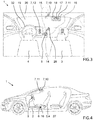
- Figure 1 schematically shows an interior of a passenger compartment of the vehicle, including a driver seat 4, a passenger seat 3, a steering wheel 32, a dashboard 24, etc.
- a first example embodiment of a vehicle system 1 according to the disclosure is described below with reference to figure 1 .
- the vehicle system 1 is configured for providing simplified use of a removable accessory 2 for a user located in the vehicle.
- the user may be seated in the passenger seat 3 side by side with the driver seat 4.
- the user may be seated in the driver seat 4, or in any of the rear seats, or any other seat of the vehicle.
- the vehicle system 1 comprises a control unit 5, a vehicle compartment holding device 6 for holding the removable accessory 2, and at least one vehicle compartment feature 7.
- the control unit 5 is configured to receive a holding signal 14 from the holding device 6, the holding signal 14 indicating if the holding device 6 is holding the removable accessory 2 or not.
- the control unit 5 is further configured to send a control signal 15 for changing a setting to the at least one vehicle compartment feature 7 in response to a change in the holding signal 14, wherein the vehicle compartment feature 7 is one of or any combination of compartment light 10, vanity mirror function 11, and compartment climate system 12.
- some kind of sensor or detector device 16 associated with the holding device 6 generates a holding signal 14 that enables the control unit 5 to determine whether the holding device 6 is holding the removable accessory 2, or whether the holding device 6 is not holding the removable accessory 2.
- the sensor or detector device 16 associated with the holding device 6 may be a proximity sensor, which for example rely on electromagnetic fields, light and/or sound for determining range to an object, thereby signaling the presence of a removable accessory in the holding device 6, or not.
- the proximity sensor may be an ultrasonic sensor.
- the removable accessory 2 may include a radio frequency (RF and RFID) tag and a transceiver arrangement at the holding device 6 may be configured for signaling the presence of a removable accessory in the holding device 6, or not.
- RF and RFID radio frequency
- the senor or detector device 16 may be a contact sensor, such as a mechanical contact switch, or light barrier sensor, configured for being sensitive to the presence of the removable accessory 2 in the holding device 6.
- the senor or detector device 16 may be a vision sensor, such as a camera, wherein the sensor or detector device, or the control unit 5, or a cloud based processing unit, may be used for executing image recognition software configured determining the presence of the removable accessory 2 in the holding device 6.
- a vision sensor such as a camera
- the sensor or detector device, or the control unit 5, or a cloud based processing unit may be used for executing image recognition software configured determining the presence of the removable accessory 2 in the holding device 6.
- the control unit 5 may be configured to monitor the holding signal 14, and to send a control signal 15 to the at least one vehicle compartment feature 7 for changing a setting thereof, in response to a change in the holding signal 14, in particular in response to detection of removal of the removable accessory 2 from the holding device 6.
- the holding signal and/or control signal 15 may be transmitted via an electrically conductive wire or via wire-less technology.
- control unit 5 may be configured to send a control signal 15 to compartment light 10 only, or vanity mirror function 11 only, or to the compartment climate system 12 only, for changing a setting thereof, in response to a change in the holding signal 14.
- compartment light 10 means the lighting arrangement for lighting up the interior of the passenger compartment.
- the compartment light 10 may thus for example corresponds to one, two or more interior lights or light assemblies arranged for illuminating the interior of the compartment.
- the one or more lights or light assemblies may be point lights, i.e. forming a substantially rounded or rectangular light source, or elongated lights, i.e. strip like light sources.
- the compartment light 10 serve to illuminate the passenger compartment for enhancing a user's or passenger's interior compartment visibility.
- the compartment light 10 may be arranged to relatively strongly illuminate the user or passenger when seated in a vehicle seat 3, 4.
- the compartment light 10 does not mean light dedicated primarily for illuminating the interior of a small storage compartment, such as a glove-compartment or the like.
- a change of setting of the compartment light 10 may thus involve a change in terms of illumination strength of the compartment light 10, e.g. a change in lumen or lux.
- vanity mirror function may refer to various different aspects that influence and provide vanity mirror functionality for a use or passenger, i.e. vanity mirror provision.
- vanity mirror function may correspond vanity mirror position in case of a moveable vanity mirror arrangement.
- the vanity mirror 17 may for example be movable between a storage position and a display position, wherein the vanity mirror 17 when located in the storage position is arranged to give the user or driver good driving and/or vehicle exterior visibility, and thus not to conceal or block exterior visibility.
- the vanity mirror 17 when located in the display position may be arranged to provide the user or driver with good self-visibility, in particular of the driver's or user's own face and/or hair.
- vanity mirror 17 may be arranged in front of the face of a driver or user when being located in the display mode.
- the vanity mirror 17 may be configured to be moved, folded, pivoted or slided between the storage position and display position.
- vanity mirror function may correspond to mirror visibility in case of a moveable mirror cover or mirror cover with adjustable transparency.
- the vanity mirror 17 may thus be stationary while the mirror cover position or mirror cover transparency may be adjustable for enabling a user selective access to a vanity mirror.
- Figure 2 schematically shows a further example of interior of a passenger compartment of the vehicle, including a driver seat 4, a steering wheel 32, a dashboard 24, a roof, a windscreen 19, etc.
- the vanity mirror function may correspond to setting a vehicle electronic display 21 that may be set in a selfie mode.
- Selfie mode involves for example recording moving images using a camera 22 and displaying the recorded movie in real-time on the electronic display 21.
- the camera 22 may for example be integrated in the same unit as the electronic display 21, as shown in figure 2 .
- the camera 22 may be mounted separately from the display 21.
- the electronic display 21 may for example be a stationary vehicle display, such as a dashboard-mounted display.
- the electronic display may be moveable between a storage position and a display position.
- the vanity mirror function may, according to still a further example, correspond to vanity mirror light 18, i.e. a dedicated light source 18 configured for illuminating a user that is located in front of the vanity mirror 17 or the electronic display 21.
- the vanity mirror light 18 may for example be positioned adjacent the vanity mirror 17 or electronic display 21, e.g. on the same unit as the vanity mirror 17 or electronic display 21.
- the vanity mirror light 18 may be located at a suitable location in the passenger compartment, such as for example in the interior roof 20, at any of the side pillars 23, at the dashboard 24, at the vehicle center console 25, or the like.
- a change of setting of the vanity mirror function may thus for example involve movement of the vanity mirror between a storage position and a display position, or a change in mirror visibility in case of a moveable mirror cover or mirror cover with adjustable transparency, or setting the vehicle electronic display in a selfie mode, or a change in vanity mirror light intensity.
- compartment climate system 12 corresponds for example to the vehicle HVAC system, i.e. heating, ventilation and air conditioning system arranged for providing indoor and automotive ambient comfort.
- a change of setting of the compartment climate system 12 may thus for example involve a change in air temperature of the ventilation air entering the passenger compartment via air vents, or a change in air flow direction of the ventilation air entering the passenger compartment via air vents, or a change in air velocity (distance traveled per unit of time) or air volume flow (m 3 per unit of time) of the ventilation air entering the passenger compartment via air vents.
- a change of setting of the compartment climate system 12 may for example involve temporary reducing air temperature of the ventilation air entering the passenger compartment via air vents in case the removable accessory is a hair dryer, for the purpose of proactively avoiding cabin temperature increase caused by operation of the hair dryer.
- a change of setting of the compartment climate system 12 may for example involve temporary increasing air velocity or air volume flow of the ventilation air entering the passenger compartment at an air vent that is located closest or adjacent to the seat of the user that removed the removable accessory from the holding device 6, thereby enabling improved drying of for example applied nail polish, or improved ventilation for more quickly diluting evaporated organic solvent of for example a nail polish remover.
- the vehicle may comprise a plurality of seats 3,4 for vehicle passengers
- the control unit 5 may be configured to determining a seating location of a user removing a removable accessory 2 from the holding device 6, and based on the determined seating location, changing the setting of the vehicle compartment feature 7, i.e. changing the setting of one or more vehicle compartment features 7 associated with the seat in which the user that removed a removable accessory 2 from the holding device 6 is seated.
- control unit 5 may be configured to determining a seating location of a user removing a removable accessory 2 from the holding device 6, and subsequently, based on the determined seating location, changing the setting of the vehicle compartment feature 7.
- the control unit 5 will determine that the user is seated in the passenger seat 3, and subsequently changing the setting of the vehicle compartment feature 7 associated with the seat of the user, i.e. the passenger seat 3.
- the compartment lighting illuminating the passenger seat 3 may increase, and/or a vanity mirror function associated with the passenger seat 3 may be triggered, and/or the air temperature/flow exiting the air vents adjacent the passenger seat 3 may be adjusted, in response to removal of the removable accessory from the holding device of the passenger seat 3.
- Figure 3 and figure 4 each show similar example embodiments of the vehicle system according to the disclosure, but with small variations and in different views.
- the vehicle compartment features 7 are provided in form of a compartment light 10 that is illustrated as light source mounted in the interior roof 20 of the vehicle, and in form of a vanity mirror function 11 that is illustrated as a moveable vanity mirror 17 having integrated vanity mirror light 18 and being foldably mounted in the interior roof 20 of the vehicle, and additionally in form of a compartment climate system 12.
- the example embodiment of the vehicle system shown in figure 3 further includes a user input control device 26 that is configured for enabling a user to manually, or by voice-control, change the setting of the vehicle compartment feature 7. Consequently, the control unit 5 may receive a user input signal from the user input control device 26 indicating that the user wishes a change in setting of the at least one vehicle compartment feature 7.
- the vehicle compartment feature 7 is a vanity mirror 17
- the vanity mirror 17 may be folded down to a display position, or up to a storage position, if the user actuates the user input control device 26.
- the vehicle compartment features 7 are provided in form of a compartment light 10 that is illustrated as light source mounted in the interior roof 20 of the vehicle, and in form of a vanity mirror function 11 that is illustrated as a moveable vanity mirror 17 that is foldably mounted in the interior roof 20 of the vehicle.
- the holding device 6 is illustrated as being integrated in a vehicle seat 3, 4, or being positioned under the seat 3,4, and a sensor or detector device 16 associated with the holding device 6 is provided for generating a holding signal 14 that enables the control unit 5 to determine whether the holding device 6 is holding the removable accessory 2, or whether the holding device 6 is not holding the removable accessory 2.
- Figure 4 schematically illustrates a situation where the removable accessory 2 just has been removed from the holding device 6, and wherein the control unit 5 has controlled a vanity mirror 17 to fold down from a storage position to the display position, and activation of a compartment light 10.
- Figure 1 and figure 4 have illustrated the holding device 6 integrated in a vehicle seat 3, 4, or being positioned under the seat 3,4.
- one or more holding device may be located at various locations within the vehicle for providing good access thereto for one or more users, independent of the user's seat of the vehicle.
- one or more holding devices 6 may be provided adjacent the rear seats of the vehicle for enabling a user sitting in the rear sear access easy to the removable accessory, and automatic provision of vanity mirror function.
- the holding device may be arranged at a seat of the vehicle, or at an entrance door of the vehicle, or at a passenger leg space of the vehicle, or at a vehicle center console, or at a vehicle dashboard, or at a vehicle interior roof, or the like.
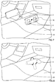
- figure 5 shows the passenger leg space 27 of the vehicle and a holding device 6 fastened to a side surface of the vehicle center console 25.
- the holding device 6 may comprise a non-closable container having a top opening for enabling easy removal and/or insertion of the removable accessory 2 from/into the holding device 6.
- a sensor or detector device 16 associated with the holding device 6 is provided for generating a holding signal 14 that enables the control unit 5 to determine whether the holding device 6 is holding the removable accessory 2, or whether the holding device 6 is not holding the removable accessory 2.
- Figure 7 shows schematically still a further example embodiment of the vehicle system, wherein the holding device 6 is fastened to a side surface of the vehicle center console 25 associated with the passenger leg space 27.
- the holding device 6 comprises two hook-shaped members that jointly are arranged to form a support surface suitable for holding the removable accessory 2, wherein the removable accessory 2 may be simple inserted or removed from holding device.
- a sensor or detector device 16 associated with the holding device 6 is provided for generating a holding signal 14 that enables the control unit 5 to determine whether the holding device 6 is holding the removable accessory 2, or whether the holding device 6 is not holding the removable accessory 2.
- the removable accessory 2 may for example be a removable container including at least one vanity item.
- the container may be an openable and closable hard shell box, a soft shell bag, or the like.
- the vanity item stored within the container may for example be a make-up item, a make-up remover item, a hair dryer, a shaving item, a hair styling tool, a nail polish item or nail polish remover.
- the removable accessory 2 may be a removable vanity item itself.
- FIG 8 An example embodiment of such a scenario is illustrated in figure 8 , wherein the holding device 6 is fastened to a side surface of the vehicle center console 25 associated with the passenger leg space 27, and wherein the holding device 6 comprises a hook-shaped member that is arranged to hold a removable accessory 2 in form of a hair dryer.
- the hair dryer may be simple inserted or removed from holding device 6, and a sensor or detector device 16 associated with the holding device 6 is provided for generating a holding signal 14 that enables the control unit 5 to determine whether the holding device 6 is holding the removable accessory 2, or whether the holding device 6 is not holding the removable accessory 2.
- the holding signal 14 is configured to indicate if the holding device 6 is holding the removable accessory 2 or not.
- the holding device 6 may be an openable and closeable storage compartment, such as an openable and closeable glove-box, an openable and closeable dashboard storage compartment, or an openable and closeable storage drawer under the seat.
- the first position may correspond to a closed state of such storage compartment
- the second position may correspond to an open state, or at least a non-closed state, of said storage compartment.
- the holding device 6 may be an openable and closeable clamping or gripping device that may be arranged to be opened for enabling removal of the removable accessory 2 from the holding device 6, and closed for enabling clamping or securement of the removable accessory 2 to the holding device 6. Furthermore, the first position may then correspond to a closed state of the holding device 6, and the second position may correspond to an open state, or at least a non-closed state, of the holding device 6.
- the clamping or gripping device may for example be switched from an open to a closed state by a manual actuation of a locking mechanism, such as a locking lever.
- the control unit 5 When monitoring the current setting of a holding device 6 that may be set in first and a second position, the control unit 5 may be configured to receive a holding signal 14 from the holding device 6, wherein the holding signal indicates if the holding device is in a first or second position. The control unit 5 is then configured to send a control signal 15 for changing a setting to the at least one vehicle compartment feature 7 in response to a change in the holding signal 14, wherein the vehicle compartment feature 7 is one of or any combination of compartment light 10, vanity mirror function 11, and compartment climate system 12.
- FIG. 9a shows a holding device in form of a glove-box 28 having an openable and closable lid 30.
- Figure 9a shows the holding device 6, e.g. the glove-box 28, in a first position corresponding to the closed state of the lid 30, and with the removable accessory 2, such as a vanity bag, being stored within the glove-box 28.
- Figure 9b shows the glove-box 28 in the second position corresponding to the opened state of the lid 30, and with the removable accessory 2 being removed from the glove-box 28.
- some kind of sensor or detector device 29 associated with the holding device 6 instead of monitoring and detecting the presence of the removable accessory 2 within the glove-box 28, some kind of sensor or detector device 29 associated with the holding device 6 generates a holding signal 14 that enables the control unit 5 to determine whether the holding device 6 is in the first or second position, e.g. whether the lid 30 is in an closed or opened state.
- the sensor or detector device 29 is arranged for detecting and distinguishing between a closed and opened lid 30, and may for example be arranged to detect the lid 30 when the lid 30 is located in the closed state.
- the sensor or detector device 29 may be designed and located to accurately and reliably detect for example the closed state of the glove-box 28.
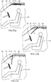
- Figures 10a and 10b show part of an example embodiment of the vehicle system including a moveable vanity mirror 17 or electronic display 21 that may be set in a selfie mode for providing the function of a vanity mirror, similar to the example embodiments of figure 1 , 3 and 4 , which also show a moveable vanity mirror 17 arranged in the interior roof 20 of the vehicle.
- the moveable vanity mirror 17 or electronic display 21 is arranged in the interior roof 20 in front of the driver, such that the moveable vanity mirror 17 or electronic display 21 may be moved between a storage position, as shown in figure 10a , and a display position, as shown in figure 10b .
- the size and position of the moveable vanity mirror 17 or electronic display 21 in the display position may conceal and block the driver's view of the road ahead.
- control unit 5 may be configured for obtaining a vehicle operating state and determining whether the current vehicle operating state is a safe state for moving the vanity mirror 17 or electronic display 21 from the storage position to the display position, and inhibiting any such movement of the moveable vanity mirror 17 or electronic display 21 when the current vehicle operating state is not in a safe state.
- a safe state may for example corresponds to a stationary vehicle or a vehicle operating in a self-driving mode.
- changing the setting to the at least one vehicle compartment feature in response to a change in the holding signal may involve moving a vanity mirror 17 or electronic display 21 that may be set in a selfie mode from a storage position to a display position, and wherein the vehicle comprises a recess 31 in the vehicle interior roof 20 for receiving the vanity mirror or electronic display 21 when being positioned in the storage position.
- Figures 11a - 11c show a sectional side-view of the moveable vanity mirror 17 or electronic display 21 that may be set in a selfie mode described with reference to figures 10a-10b in a storage position, an intermediate position, and a display position, respectively.
- the motion mechanism controlling the motion of the moveable vanity mirror 17 or electronic display 21 may include an actuator, such as an electrical motor, and suitable linkage arms, guiding channels, and/or pivoting shafts, depending on the desired motion trajectory of the moveable vanity mirror 17 or electronic display 21.
- the vanity mirror 17 or electronic display 21 may be used.
- the vanity mirror may possibly be a flexible mirror or roll-up mirror, thereby enabling other types of motion mechanisms.
- the method comprises a first step S10 of monitoring, by means of a vehicle control unit 5, a state of a holding device 6 for holding the removable accessory 2.
- a first state may correspond to when the holding device 6 is holding the removable accessory 2 and a second state may correspond to when the holding device 6 is not holding the removable accessory 2.
- a first state may correspond to when the holding device is in a first position and a second state may correspond to when the holding device is in a second position
- the method further comprises a second step S20 of changing, when the state changes, a setting to at least one vehicle compartment feature 7 by means of the vehicle control unit 5, wherein the at least one vehicle compartment feature 7 is one of or any combination of compartment light 10, vanity mirror function 11, and compartment climate system 12.
- the method may optionally include a first intermediate step S11 of obtaining information about the vehicle operating state by means of the vehicle control unit 5 and determining whether the current vehicle operating state is a safe state for changing the setting to the at least one vehicle compartment feature 7, or whether the current vehicle operating state is an unsafe state for changing the setting to the at least one vehicle compartment feature 7.
- the method may then include a subsequent intermediate step S12 of inhibiting any change of setting to the at least one vehicle compartment feature 7 unless the current vehicle operating state is the safe state.
- the safe state may for example correspond to a stationary vehicle or a vehicle operating in a self-driving mode. Furthermore, detection and checking of safe state is primarily or only relevant when the vehicle driver removes the removable accessory from a holding device associated with the driver seat, because only the vehicle driver may need restrainment from distractive activity while driving.
- figure 14 shows the method described with reference to figure 12 , but with more details relating to the type of change of state and the result.
- the method comprises the first step S10 of monitoring, by means of a vehicle control unit 5, a state of a holding device 6 for holding the removable accessory 2, wherein the first state corresponds to when the holding device 6 is holding the removable accessory 2 and the second state corresponds to when the holding device 6 is not holding the removable accessory 2, or wherein the first state corresponds to when the holding device is in a first position and the second state corresponds to when the holding device is in a second position.
- the method further comprises a second step S20a of increasing the intensity in compartment light 10 by means of the vehicle control unit 5 when the state of the holding device 6 goes from the first state to the second state, and a third step S20b of decreasing the intensity in compartment light 10 by means of the vehicle control unit 5 when the state of the holding device 6 goes from the second state to the first state.
- the method may comprise a second step S20a of increasing an intensity in vanity mirror light 18 by means of the vehicle control unit 5 when the state of the holding device 6 goes from the first state to the second state, and a third step S20b of decreasing the intensity in vanity mirror light 18 by means of the vehicle control unit 5 when the state of the holding device 6 goes from the second state to the first state.
- the method may comprise a second step S20a of initiating display of a vanity mirror 17, or initiating selfie mode of an electronic display 21, by means of the vehicle control unit 5 when the state of the holding device 6 goes from the first state to the second state, and a third step S20b of terminating display of the vanity mirror 17, or terminating the selfie mode of the electronic display 21, by means of the vehicle control unit 5 when the state of the holding device 6 goes from the second state to the first state.
- the vehicle system and associated method may be implemented in self-driving vehicles lacking a steering wheel.
- Different method steps than those described above, performing the method by hardware or software, may be provided within the scope of the disclosure.
- the method described with reference to figure 14 may of course be altered to include also the first and second intermediate steps S11,S12 described with reference to figure 13 .
Landscapes
- Engineering & Computer Science (AREA)
- Mechanical Engineering (AREA)
- Chemical & Material Sciences (AREA)
- Combustion & Propulsion (AREA)
- Transportation (AREA)
- Physics & Mathematics (AREA)
- Thermal Sciences (AREA)
- Fittings On The Vehicle Exterior For Carrying Loads, And Devices For Holding Or Mounting Articles (AREA)
- Vehicle Step Arrangements And Article Storage (AREA)
Abstract
Description
- The present disclosure relates to a vehicle system comprising a control unit, a vehicle compartment holding device for holding a removable accessory, and at least one vehicle compartment feature. The disclosure further relates to a computer-implemented method for simplifying use of a removable accessory.
- The vehicle system and method according to the disclosure can be arranged in a conventional vehicles configured to be steered by a user, as well as self-driving vehicles.
- Moreover, even if the vehicle system according to the disclosure will be described primarily in relation to a car, the vehicle system is not restricted to this particular vehicle, but may as well be installed in another type of vehicle, such as a truck, a bus, a rail vehicle, a flying vehicle, a marine vessel, or the like.
- Vehicle systems including a removable accessory are known in the prior art. For example, document
US5884008A shows a portable hair dryer for use in a vehicle, which portable hair dryer has a handle switch responsive to pivoting and vehicle battery voltage indicator. - However, there is a demand for providing simplified use of said removable accessory for a user located in the vehicle, for example during vehicle stillstand and/or vehicle travel.
- An object of the present disclosure is to provide a vehicle system comprising a control unit, a vehicle compartment holding device for holding a removable accessory, and at least one vehicle compartment feature that provides simplified use of said removable accessory for a user located in the vehicle. This object is at least partly achieved by the features of the independent claims.
- According to a first aspect of the present disclosure, there is provided a vehicle system comprising a control unit, a vehicle compartment holding device for holding a removable accessory, and at least one vehicle compartment feature, wherein the control unit is configured to receive a holding signal from the holding device. The holding signal indicating if the holding device is holding the removable accessory or not, or if the holding device is in a first or second position. The control unit is further configured to send a control signal for changing a setting to the at least one vehicle compartment feature in response to a change in the holding signal, wherein the vehicle compartment feature is one of or any combination of compartment light, vanity mirror function, and compartment climate system.
- According to a second aspect of the present disclosure, there is provided a computer-implemented method for simplifying use of a removable accessory in a vehicle. The method comprises monitoring, by means of a vehicle control unit, a state of a holding device for holding the removable accessory, wherein a first state corresponds to when the holding device is holding the removable accessory and a second state corresponds to when the holding device is not holding the removable accessory, or wherein a first state corresponds to when the holding device is in a first position and a second state corresponds to when the holding device is in a second position. The method further comprising, when the state changes, changing a setting to at least one vehicle compartment feature by means of the vehicle control unit, wherein the at least one vehicle compartment feature is one of or any combination of compartment light, vanity mirror function, and compartment climate system.
- In this way, the user may enjoy and benefit from automatic change of setting of the at least one vehicle compartment feature as soon as the user initiates use of the removable accessory. Thereby, the user does not need to also manually control the setting of the at least one vehicle compartment feature, which manual control may require good knowledge of the vehicle control interface and vehicle features, and additionally be inconvenient.
- Further advantages are achieved by implementing one or several of the features of the dependent claims.
- In some example embodiments, the vehicle system further comprises a removable accessory in form of a removable container including at least one vanity item, or in form of a removable vanity item. On other words, when a user desires to carry out some cosmetic, beauty or hair self-care, the user may simply remove the removable accessory from the holding device and gain access to a vanity item, and due to automatic change of setting of at least one of compartment light, vanity mirror function, and compartment climate system, the cosmetic, beauty or hair self-care is simplified.
- In some example embodiments, the vanity item is a make-up item, a make-up remover item, a hair dryer, a shaving item, a hair styling tool, a nail polish item or nail polish remover.
- In some example embodiments, the holding device is an openable and closeable storage compartment or an openable and closeable clamping device. Thereby, undesired displacement of the removable accessory, for example during driving, may be prevented. Moreover, the holding signal may relatively simply be arranged to indicate whether the holding device is in a first or second position, namely by monitoring whether the openable and closeable storage compartment or the openable and closeable clamping device is in a closed state or opened state.
- The disclosure also relates to a vehicle comprising a system as described above.
- In some example embodiments, the holding device is arranged at a seat of the vehicle, at an entrance door of the vehicle, at a passenger leg space of the vehicle, at a vehicle center console, at a vehicle dashboard, or at a vehicle interior roof. Common for these locations are easy access to the removable accessory, which is held by the holding device, by a user while being seated in a vehicle seat.
- In some example embodiments, the step of changing the setting to the at least one vehicle compartment feature in response to a change in the holding signal involves moving a vanity mirror or electronic display that may be set in a selfie mode from a storage position to a display position, and wherein the vehicle comprises a recess in the roof for receiving the vanity mirror or electronic display when being positioned in the storage position. In other words, when the user removes the removable accessory from the holding device, the vanity mirror or electronic display that may carry out a mirror functionality, automatically moves from the storage position in a recess in the roof to a display position in front of the user for simplifying cosmetic, beauty or hair self-care.
- In some example embodiments, the vehicle comprises a plurality of seats for vehicle passengers, and the control unit is configured to determining a seating location of a user removing a removable accessory from the holding device, and based on the determined seating location, changing the setting of the vehicle compartment feature. Thereby, the vehicle system may adapt the change of setting of the vehicle compartment feature specifically to the seat of the relevant user.
- In other words, in a vehicle having at least a first seat and a second seat, each being associated with an individual holding device adapted for holding an individual removable accessory, a removal of the removable accessory from the holding device associated with the first seat will then result in a change of setting of the vehicle compartment feature specifically directed towards a user seated in the first seat, while only little or substantially no change of setting of the vehicle compartment feature will occur for the user seated in the second seat. For example, if the vehicle compartment feature is vanity mirror function, such as for example motion of a first vanity mirror from a storage position to a display position, the user seated in the first seat will be provided with a vanity mirror function, while the user seated in the second seat will not be provided with a vanity mirror function, i.e. a second vanity mirror will remain in the storage position.
- In some example embodiments, the removable compartment accessory is a removable container with at least one vanity item, or a removable vanity item.
- In some example embodiments, changing the setting to the at least one vehicle compartment feature involves the steps of increasing the intensity in compartment light by means of the vehicle control unit when the state of the holding device goes from the first state to the second state, and decreasing the intensity in compartment light by means of the vehicle control unit when the state of the holding device goes from the second state to the first state. Consequently, removal of the removable accessory from the holding device will result in increased compartment light intensity, and putting back the removable accessory to the holding device will result in decreased compartment light intensity.
- In some example embodiments, changing the setting to at least one vehicle compartment feature involves increasing an intensity in vanity mirror light by means of the vehicle control unit when the state of the holding device goes from the first state to the second state, and decreasing the intensity in vanity mirror light by means of the vehicle control unit when the state of the holding device goes from the second state to the first state. Consequently, removal of the removable accessory from the holding device will result in increased vanity mirror light intensity, and putting back the removable accessory to the holding device will result in decreased vanity mirror light intensity.
- In some example embodiments, changing the setting to at least one vehicle compartment feature involves initiating display of a vanity mirror, or initiating selfie mode of an electronic display, by means of the vehicle control unit when the state of the holding device goes from the first state to the second state, and terminating display of the vanity mirror, or terminating the selfie mode of the electronic display, by means of the vehicle control unit when the state of the holding device goes from the second state to the first state. Consequently, removal of the removable accessory from the holding device will result in provision of vanity mirror functionality, and putting back the removable accessory to the holding device will result in termination of the vanity mirror functionality.
- In some example embodiments, the method further comprises further comprises steps of obtaining a vehicle operating state by means of the vehicle control unit and determining whether the current vehicle operating state is a safe state for changing the setting to the at least one vehicle compartment feature, or whether the current vehicle operating state is an unsafe state for changing the setting to the at least one vehicle compartment feature, and inhibiting any change of setting to the at least one vehicle compartment feature unless the current vehicle operating state is the safe state. Thereby, the vehicle system restrains a vehicle driver from for example cosmetic, beauty or hair self-care during driving for avoiding driver distraction from closely following the traffic situation.
- In some example embodiments, the method further comprises wherein a safe state corresponds to a stationary vehicle or a vehicle operating in a self-driving mode.
- Further features and advantages of the invention will become apparent when studying the appended claims and the following description. The skilled person in the art realizes that different features of the present disclosure may be combined to create embodiments other than those explicitly described hereinabove and below, without departing from the scope of the present disclosure.
- The disclosure will be described in detail in the following, with reference to the attached drawings, in which
- Fig. 1
- shows schematically an interior view of a vehicle passenger compartment having an example embodiment of the vehicle system according to the disclosure,
- Fig. 2
- shows schematically a further interior view of a vehicle passenger compartment having another example embodiment of the vehicle system according to the disclosure,
- Fig. 3
- shows schematically still a further interior view of a vehicle passenger compartment having still another example embodiment of the vehicle system according to the disclosure,
- Fig. 4
- shows schematically a side of a vehicle having an example embodiment of the vehicle system according to the disclosure,
- Fig. 5
- shows schematically an example embodiment of the holding device and a removable accessory,
- Fig. 6
- shows schematically a further example embodiment of the holding device and a removable accessory,
- Fig. 7
- shows schematically still another example embodiment of the holding device and a removable accessory,
- Fig. 8
- shows schematically an example embodiment of the holding device and a removable accessory in form of a hair dryer,
- Fig. 9a, 9b
- show schematically an example embodiment of the holding device in form a storage compartment in a closed and opened state, respectively,
- Fig. 10a,10b
- show schematically an example embodiment of the vehicle compartment feature in form of a vanity mirror function, in a storage position and display position, respectively,
- Fig. 10a-11c
- show schematically a sectional view of the vanity mirror function of
figures 10a-10b in three consecutive motion states, - Fig.12
- shows a first example embodiment of a flow chart describing the method according to the disclosure,
- Fig.13
- shows a second example embodiment of a flow chart describing the method according to the disclosure, and
- Fig.14
- shows a third example embodiment of a flow chart describing the method according to the disclosure.
- Various aspects of the disclosure will hereinafter be described in conjunction with the appended drawings to illustrate and not to limit the disclosure, wherein like designations denote like elements, and variations of the described aspects are not restricted to the specifically shown embodiments, but are applicable on other variations of the disclosure.
-
Figure 1 schematically shows an interior of a passenger compartment of the vehicle, including adriver seat 4, apassenger seat 3, asteering wheel 32, adashboard 24, etc. A first example embodiment of avehicle system 1 according to the disclosure is described below with reference tofigure 1 .Thevehicle system 1 is configured for providing simplified use of aremovable accessory 2 for a user located in the vehicle. For example, the user may be seated in thepassenger seat 3 side by side with thedriver seat 4. Alternatively, the user may be seated in thedriver seat 4, or in any of the rear seats, or any other seat of the vehicle. - The
vehicle system 1 comprises acontrol unit 5, a vehiclecompartment holding device 6 for holding theremovable accessory 2, and at least one vehicle compartment feature 7. Thecontrol unit 5 is configured to receive a holdingsignal 14 from the holdingdevice 6, the holdingsignal 14 indicating if the holdingdevice 6 is holding theremovable accessory 2 or not. Thecontrol unit 5 is further configured to send acontrol signal 15 for changing a setting to the at least one vehicle compartment feature 7 in response to a change in the holdingsignal 14, wherein the vehicle compartment feature 7 is one of or any combination ofcompartment light 10, vanity mirror function 11, and compartment climate system 12. - In other words, some kind of sensor or
detector device 16 associated with the holdingdevice 6 generates a holdingsignal 14 that enables thecontrol unit 5 to determine whether the holdingdevice 6 is holding theremovable accessory 2, or whether the holdingdevice 6 is not holding theremovable accessory 2. - For example, the sensor or
detector device 16 associated with the holdingdevice 6 may be a proximity sensor, which for example rely on electromagnetic fields, light and/or sound for determining range to an object, thereby signaling the presence of a removable accessory in theholding device 6, or not. For example, the proximity sensor may be an ultrasonic sensor. According to still a further example, theremovable accessory 2 may include a radio frequency (RF and RFID) tag and a transceiver arrangement at the holdingdevice 6 may be configured for signaling the presence of a removable accessory in theholding device 6, or not. - Alternatively, the sensor or
detector device 16 may be a contact sensor, such as a mechanical contact switch, or light barrier sensor, configured for being sensitive to the presence of theremovable accessory 2 in theholding device 6. - Still more alternatively, the sensor or
detector device 16 may be a vision sensor, such as a camera, wherein the sensor or detector device, or thecontrol unit 5, or a cloud based processing unit, may be used for executing image recognition software configured determining the presence of theremovable accessory 2 in theholding device 6. - The
control unit 5 may be configured to monitor the holdingsignal 14, and to send acontrol signal 15 to the at least one vehicle compartment feature 7 for changing a setting thereof, in response to a change in the holdingsignal 14, in particular in response to detection of removal of theremovable accessory 2 from the holdingdevice 6. - The holding signal and/or
control signal 15 may be transmitted via an electrically conductive wire or via wire-less technology. - In the example embodiment of
figure 1 , three different types of vehicle compartment features 7 are illustrated being controlled by thecontrol unit 5, namelycompartment light 10, vanity mirror function 11, and compartment climate system 12. However, the vehicle system according to the disclosure may alternatively be implemented such that the control unit controls only one of these three vehicle compartment features 7, based on the received holdingsignal 14. Hence, thecontrol unit 5 may be configured to send acontrol signal 15 to compartment light 10 only, or vanity mirror function 11 only, or to the compartment climate system 12 only, for changing a setting thereof, in response to a change in the holdingsignal 14. - The term compartment light 10 means the lighting arrangement for lighting up the interior of the passenger compartment. The
compartment light 10 may thus for example corresponds to one, two or more interior lights or light assemblies arranged for illuminating the interior of the compartment. The one or more lights or light assemblies may be point lights, i.e. forming a substantially rounded or rectangular light source, or elongated lights, i.e. strip like light sources. Thecompartment light 10 serve to illuminate the passenger compartment for enhancing a user's or passenger's interior compartment visibility. In particular, thecompartment light 10 may be arranged to relatively strongly illuminate the user or passenger when seated in avehicle seat compartment light 10 does not mean light dedicated primarily for illuminating the interior of a small storage compartment, such as a glove-compartment or the like. - A change of setting of the
compartment light 10 may thus involve a change in terms of illumination strength of thecompartment light 10, e.g. a change in lumen or lux. - The term vanity mirror function may refer to various different aspects that influence and provide vanity mirror functionality for a use or passenger, i.e. vanity mirror provision. For example, vanity mirror function may correspond vanity mirror position in case of a moveable vanity mirror arrangement. The
vanity mirror 17 may for example be movable between a storage position and a display position, wherein thevanity mirror 17 when located in the storage position is arranged to give the user or driver good driving and/or vehicle exterior visibility, and thus not to conceal or block exterior visibility. - Moreover, the
vanity mirror 17 when located in the display position may be arranged to provide the user or driver with good self-visibility, in particular of the driver's or user's own face and/or hair. In other words,vanity mirror 17 may be arranged in front of the face of a driver or user when being located in the display mode. - The
vanity mirror 17 may be configured to be moved, folded, pivoted or slided between the storage position and display position. - According to a further example, vanity mirror function may correspond to mirror visibility in case of a moveable mirror cover or mirror cover with adjustable transparency. The
vanity mirror 17 may thus be stationary while the mirror cover position or mirror cover transparency may be adjustable for enabling a user selective access to a vanity mirror. -
Figure 2 schematically shows a further example of interior of a passenger compartment of the vehicle, including adriver seat 4, asteering wheel 32, adashboard 24, a roof, awindscreen 19, etc. - According to a further example, as schematically illustrated in
figure 2 , the vanity mirror function may correspond to setting a vehicleelectronic display 21 that may be set in a selfie mode. Selfie mode involves for example recording moving images using acamera 22 and displaying the recorded movie in real-time on theelectronic display 21. Thecamera 22 may for example be integrated in the same unit as theelectronic display 21, as shown infigure 2 . Alternatively, thecamera 22 may be mounted separately from thedisplay 21. Theelectronic display 21 may for example be a stationary vehicle display, such as a dashboard-mounted display. Alternatively, the electronic display may be moveable between a storage position and a display position. - With reference to
figure 1 and figure 2 , the vanity mirror function may, according to still a further example, correspond tovanity mirror light 18, i.e. a dedicatedlight source 18 configured for illuminating a user that is located in front of thevanity mirror 17 or theelectronic display 21. Thevanity mirror light 18 may for example be positioned adjacent thevanity mirror 17 orelectronic display 21, e.g. on the same unit as thevanity mirror 17 orelectronic display 21. Alternatively, thevanity mirror light 18 may be located at a suitable location in the passenger compartment, such as for example in theinterior roof 20, at any of theside pillars 23, at thedashboard 24, at thevehicle center console 25, or the like. - A change of setting of the vanity mirror function may thus for example involve movement of the vanity mirror between a storage position and a display position, or a change in mirror visibility in case of a moveable mirror cover or mirror cover with adjustable transparency, or setting the vehicle electronic display in a selfie mode, or a change in vanity mirror light intensity.
- The term compartment climate system 12 corresponds for example to the vehicle HVAC system, i.e. heating, ventilation and air conditioning system arranged for providing indoor and automotive ambient comfort.
- A change of setting of the compartment climate system 12 may thus for example involve a change in air temperature of the ventilation air entering the passenger compartment via air vents, or a change in air flow direction of the ventilation air entering the passenger compartment via air vents, or a change in air velocity (distance traveled per unit of time) or air volume flow (m3 per unit of time) of the ventilation air entering the passenger compartment via air vents.
- Specifically, a change of setting of the compartment climate system 12 may for example involve temporary reducing air temperature of the ventilation air entering the passenger compartment via air vents in case the removable accessory is a hair dryer, for the purpose of proactively avoiding cabin temperature increase caused by operation of the hair dryer. Furthermore, a change of setting of the compartment climate system 12 may for example involve temporary increasing air velocity or air volume flow of the ventilation air entering the passenger compartment at an air vent that is located closest or adjacent to the seat of the user that removed the removable accessory from the holding
device 6, thereby enabling improved drying of for example applied nail polish, or improved ventilation for more quickly diluting evaporated organic solvent of for example a nail polish remover. - According to a further example embodiment, the vehicle may comprise a plurality of
seats control unit 5 may be configured to determining a seating location of a user removing aremovable accessory 2 from the holdingdevice 6, and based on the determined seating location, changing the setting of the vehicle compartment feature 7, i.e. changing the setting of one or more vehicle compartment features 7 associated with the seat in which the user that removed aremovable accessory 2 from the holdingdevice 6 is seated. - Consequently, with reference to
figure 1 , if for example a user sitting in thepassenger seat 3 and removes a removable accessory from a holding device associated with thepassenger seat 3, thecontrol unit 5 may be configured to determining a seating location of a user removing aremovable accessory 2 from the holdingdevice 6, and subsequently, based on the determined seating location, changing the setting of the vehicle compartment feature 7. In other words, thecontrol unit 5 will determine that the user is seated in thepassenger seat 3, and subsequently changing the setting of the vehicle compartment feature 7 associated with the seat of the user, i.e. thepassenger seat 3. For example, the compartment lighting illuminating thepassenger seat 3 may increase, and/or a vanity mirror function associated with thepassenger seat 3 may be triggered, and/or the air temperature/flow exiting the air vents adjacent thepassenger seat 3 may be adjusted, in response to removal of the removable accessory from the holding device of thepassenger seat 3. -
Figure 3 and figure 4 each show similar example embodiments of the vehicle system according to the disclosure, but with small variations and in different views. Specifically, in the example embodiment offigure 3 , the vehicle compartment features 7 are provided in form of acompartment light 10 that is illustrated as light source mounted in theinterior roof 20 of the vehicle, and in form of a vanity mirror function 11 that is illustrated as amoveable vanity mirror 17 having integratedvanity mirror light 18 and being foldably mounted in theinterior roof 20 of the vehicle, and additionally in form of a compartment climate system 12. - The example embodiment of the vehicle system shown in
figure 3 further includes a userinput control device 26 that is configured for enabling a user to manually, or by voice-control, change the setting of the vehicle compartment feature 7. Consequently, thecontrol unit 5 may receive a user input signal from the userinput control device 26 indicating that the user wishes a change in setting of the at least one vehicle compartment feature 7. In other words, if for example the vehicle compartment feature 7 is avanity mirror 17, thevanity mirror 17 may be folded down to a display position, or up to a storage position, if the user actuates the userinput control device 26. - In the example embodiment of
figure 4 , the vehicle compartment features 7 are provided in form of acompartment light 10 that is illustrated as light source mounted in theinterior roof 20 of the vehicle, and in form of a vanity mirror function 11 that is illustrated as amoveable vanity mirror 17 that is foldably mounted in theinterior roof 20 of the vehicle. The holdingdevice 6 is illustrated as being integrated in avehicle seat seat detector device 16 associated with the holdingdevice 6 is provided for generating a holdingsignal 14 that enables thecontrol unit 5 to determine whether the holdingdevice 6 is holding theremovable accessory 2, or whether the holdingdevice 6 is not holding theremovable accessory 2. -
Figure 4 schematically illustrates a situation where theremovable accessory 2 just has been removed from the holdingdevice 6, and wherein thecontrol unit 5 has controlled avanity mirror 17 to fold down from a storage position to the display position, and activation of acompartment light 10. -
Figure 1 andfigure 4 have illustrated theholding device 6 integrated in avehicle seat seat - In other words, one or
more holding devices 6 may be provided adjacent the rear seats of the vehicle for enabling a user sitting in the rear sear access easy to the removable accessory, and automatic provision of vanity mirror function. In some example embodiments, the holding device may be arranged at a seat of the vehicle, or at an entrance door of the vehicle, or at a passenger leg space of the vehicle, or at a vehicle center console, or at a vehicle dashboard, or at a vehicle interior roof, or the like. - As an example,
figure 5 shows thepassenger leg space 27 of the vehicle and aholding device 6 fastened to a side surface of thevehicle center console 25. Moreover, the holdingdevice 6 may comprise a non-closable container having a top opening for enabling easy removal and/or insertion of theremovable accessory 2 from/into the holdingdevice 6. A sensor ordetector device 16 associated with the holdingdevice 6 is provided for generating a holdingsignal 14 that enables thecontrol unit 5 to determine whether the holdingdevice 6 is holding theremovable accessory 2, or whether the holdingdevice 6 is not holding theremovable accessory 2. -
Figure 7 shows schematically still a further example embodiment of the vehicle system, wherein the holdingdevice 6 is fastened to a side surface of thevehicle center console 25 associated with thepassenger leg space 27. The holdingdevice 6 comprises two hook-shaped members that jointly are arranged to form a support surface suitable for holding theremovable accessory 2, wherein theremovable accessory 2 may be simple inserted or removed from holding device. A sensor ordetector device 16 associated with the holdingdevice 6 is provided for generating a holdingsignal 14 that enables thecontrol unit 5 to determine whether the holdingdevice 6 is holding theremovable accessory 2, or whether the holdingdevice 6 is not holding theremovable accessory 2. - The
removable accessory 2 may for example be a removable container including at least one vanity item. The container may be an openable and closable hard shell box, a soft shell bag, or the like. The vanity item stored within the container may for example be a make-up item, a make-up remover item, a hair dryer, a shaving item, a hair styling tool, a nail polish item or nail polish remover. - Alternatively, the
removable accessory 2 may be a removable vanity item itself. An example embodiment of such a scenario is illustrated infigure 8 , wherein the holdingdevice 6 is fastened to a side surface of thevehicle center console 25 associated with thepassenger leg space 27, and wherein the holdingdevice 6 comprises a hook-shaped member that is arranged to hold aremovable accessory 2 in form of a hair dryer. The hair dryer may be simple inserted or removed from holdingdevice 6, and a sensor ordetector device 16 associated with the holdingdevice 6 is provided for generating a holdingsignal 14 that enables thecontrol unit 5 to determine whether the holdingdevice 6 is holding theremovable accessory 2, or whether the holdingdevice 6 is not holding theremovable accessory 2. - In the example embodiments of
figure 1 and4-8 , the holdingsignal 14 is configured to indicate if the holdingdevice 6 is holding theremovable accessory 2 or not. However, in certain implementations, it may be difficult to correctly and reliably determining a holding status of the holdingdevice 6, i.e. to determine whether theremovable accessory 2 is located within the holdingdevice 6, or not. In such case, it may sometimes be possible to instead monitoring the current setting of the holdingdevice 6, which may be set in first and a second position. - For example, the holding
device 6 may be an openable and closeable storage compartment, such as an openable and closeable glove-box, an openable and closeable dashboard storage compartment, or an openable and closeable storage drawer under the seat. Furthermore, the first position may correspond to a closed state of such storage compartment, and the second position may correspond to an open state, or at least a non-closed state, of said storage compartment. - Alternatively, the holding
device 6 may be an openable and closeable clamping or gripping device that may be arranged to be opened for enabling removal of theremovable accessory 2 from the holdingdevice 6, and closed for enabling clamping or securement of theremovable accessory 2 to theholding device 6. Furthermore, the first position may then correspond to a closed state of the holdingdevice 6, and the second position may correspond to an open state, or at least a non-closed state, of the holdingdevice 6. The clamping or gripping device may for example be switched from an open to a closed state by a manual actuation of a locking mechanism, such as a locking lever. - When monitoring the current setting of a
holding device 6 that may be set in first and a second position, thecontrol unit 5 may be configured to receive a holdingsignal 14 from the holdingdevice 6, wherein the holding signal indicates if the holding device is in a first or second position. Thecontrol unit 5 is then configured to send acontrol signal 15 for changing a setting to the at least one vehicle compartment feature 7 in response to a change in the holdingsignal 14, wherein the vehicle compartment feature 7 is one of or any combination ofcompartment light 10, vanity mirror function 11, and compartment climate system 12. - Such a scenario is schematically illustrated in
figures 9a and 9b , which shows a holding device in form of a glove-box 28 having an openable andclosable lid 30.Figure 9a shows the holdingdevice 6, e.g. the glove-box 28, in a first position corresponding to the closed state of thelid 30, and with theremovable accessory 2, such as a vanity bag, being stored within the glove-box 28.Figure 9b shows the glove-box 28 in the second position corresponding to the opened state of thelid 30, and with theremovable accessory 2 being removed from the glove-box 28. - Consequently, instead of monitoring and detecting the presence of the
removable accessory 2 within the glove-box 28, some kind of sensor ordetector device 29 associated with the holdingdevice 6 generates a holdingsignal 14 that enables thecontrol unit 5 to determine whether the holdingdevice 6 is in the first or second position, e.g. whether thelid 30 is in an closed or opened state. Infigures 9a and 9b , the sensor ordetector device 29 is arranged for detecting and distinguishing between a closed and openedlid 30, and may for example be arranged to detect thelid 30 when thelid 30 is located in the closed state. - Since the relative position of the glove-box 28 and
lid 30 in the closed state is generally very well-defined, the sensor ordetector device 29 may be designed and located to accurately and reliably detect for example the closed state of the glove-box 28. The same applies to all types of openable and closeable storage compartments and openable and closeable clamping or gripping device. -
Figures 10a and 10b show part of an example embodiment of the vehicle system including amoveable vanity mirror 17 orelectronic display 21 that may be set in a selfie mode for providing the function of a vanity mirror, similar to the example embodiments offigure 1 ,3 and 4 , which also show amoveable vanity mirror 17 arranged in theinterior roof 20 of the vehicle. In the example embodiment offigures 10a-10b , themoveable vanity mirror 17 orelectronic display 21 is arranged in theinterior roof 20 in front of the driver, such that themoveable vanity mirror 17 orelectronic display 21 may be moved between a storage position, as shown infigure 10a , and a display position, as shown infigure 10b . - The size and position of the
moveable vanity mirror 17 orelectronic display 21 in the display position may conceal and block the driver's view of the road ahead. - Therefore, the
control unit 5 may be configured for obtaining a vehicle operating state and determining whether the current vehicle operating state is a safe state for moving thevanity mirror 17 orelectronic display 21 from the storage position to the display position, and inhibiting any such movement of themoveable vanity mirror 17 orelectronic display 21 when the current vehicle operating state is not in a safe state. A safe state may for example corresponds to a stationary vehicle or a vehicle operating in a self-driving mode. - When the vehicle is in a safe state, changing the setting to the at least one vehicle compartment feature in response to a change in the holding signal may involve moving a
vanity mirror 17 orelectronic display 21 that may be set in a selfie mode from a storage position to a display position, and wherein the vehicle comprises arecess 31 in the vehicleinterior roof 20 for receiving the vanity mirror orelectronic display 21 when being positioned in the storage position. -
Figures 11a - 11c show a sectional side-view of themoveable vanity mirror 17 orelectronic display 21 that may be set in a selfie mode described with reference tofigures 10a-10b in a storage position, an intermediate position, and a display position, respectively. The motion mechanism controlling the motion of themoveable vanity mirror 17 orelectronic display 21 may include an actuator, such as an electrical motor, and suitable linkage arms, guiding channels, and/or pivoting shafts, depending on the desired motion trajectory of themoveable vanity mirror 17 orelectronic display 21. - Depending on size of the
vanity mirror 17 orelectronic display 21, other types of motion mechanisms may be used. Moreover, the vanity mirror may possibly be a flexible mirror or roll-up mirror, thereby enabling other types of motion mechanisms. - A first example embodiment of a computer-implemented method for simplifying use of a
removable accessory 2 in a vehicle will be described below with reference tofigure 12 . The method comprises a first step S10 of monitoring, by means of avehicle control unit 5, a state of aholding device 6 for holding theremovable accessory 2. - A first state may correspond to when the holding
device 6 is holding theremovable accessory 2 and a second state may correspond to when the holdingdevice 6 is not holding theremovable accessory 2. - Alternatively, a first state may correspond to when the holding device is in a first position and a second state may correspond to when the holding device is in a second position
- The method further comprises a second step S20 of changing, when the state changes, a setting to at least one vehicle compartment feature 7 by means of the
vehicle control unit 5, wherein the at least one vehicle compartment feature 7 is one of or any combination ofcompartment light 10, vanity mirror function 11, and compartment climate system 12. - As described with reference to
figure 13 , the method may optionally include a first intermediate step S11 of obtaining information about the vehicle operating state by means of thevehicle control unit 5 and determining whether the current vehicle operating state is a safe state for changing the setting to the at least one vehicle compartment feature 7, or whether the current vehicle operating state is an unsafe state for changing the setting to the at least one vehicle compartment feature 7. The method may then include a subsequent intermediate step S12 of inhibiting any change of setting to the at least one vehicle compartment feature 7 unless the current vehicle operating state is the safe state. - The safe state may for example correspond to a stationary vehicle or a vehicle operating in a self-driving mode. Furthermore, detection and checking of safe state is primarily or only relevant when the vehicle driver removes the removable accessory from a holding device associated with the driver seat, because only the vehicle driver may need restrainment from distractive activity while driving.
- Some example operation scenarios of the vehicle system will be described below with reference to
figure 14 , which shows the method described with reference tofigure 12 , but with more details relating to the type of change of state and the result. - The method comprises the first step S10 of monitoring, by means of a
vehicle control unit 5, a state of aholding device 6 for holding theremovable accessory 2, wherein the first state corresponds to when the holdingdevice 6 is holding theremovable accessory 2 and the second state corresponds to when the holdingdevice 6 is not holding theremovable accessory 2, or wherein the first state corresponds to when the holding device is in a first position and the second state corresponds to when the holding device is in a second position. - The method further comprises a second step S20a of increasing the intensity in
compartment light 10 by means of thevehicle control unit 5 when the state of the holdingdevice 6 goes from the first state to the second state, and a third step S20b of decreasing the intensity incompartment light 10 by means of thevehicle control unit 5 when the state of the holdingdevice 6 goes from the second state to the first state. - Alternatively, on in combination with the method described above, the method may comprise a second step S20a of increasing an intensity in
vanity mirror light 18 by means of thevehicle control unit 5 when the state of the holdingdevice 6 goes from the first state to the second state, and a third step S20b of decreasing the intensity invanity mirror light 18 by means of thevehicle control unit 5 when the state of the holdingdevice 6 goes from the second state to the first state. - According to yet a further alternative embodiment, that may be combined with the methods described above, the method may comprise a second step S20a of initiating display of a
vanity mirror 17, or initiating selfie mode of anelectronic display 21, by means of thevehicle control unit 5 when the state of the holdingdevice 6 goes from the first state to the second state, and a third step S20b of terminating display of thevanity mirror 17, or terminating the selfie mode of theelectronic display 21, by means of thevehicle control unit 5 when the state of the holdingdevice 6 goes from the second state to the first state. - The present disclosure has been presented above with reference to specific embodiments. However, other embodiments than the above described are possible and within the scope of the disclosure. For example, the vehicle system and associated method may be implemented in self-driving vehicles lacking a steering wheel. Different method steps than those described above, performing the method by hardware or software, may be provided within the scope of the disclosure. For example, the method described with reference to
figure 14 may of course be altered to include also the first and second intermediate steps S11,S12 described with reference tofigure 13 . - It will be appreciated that the above description is merely exemplary in nature and is not intended to limit the present disclosure, its application or uses. While specific examples have been described in the specification and illustrated in the drawings, it will be understood by those of ordinary skill in the art that various changes may be made and equivalents may be substituted for elements thereof without departing from the scope of the present disclosure as defined in the claims. Furthermore, modifications may be made to adapt a particular situation or material to the teachings of the present disclosure without departing from the essential scope thereof.
- Therefore, it is intended that the present disclosure not be limited to the particular examples illustrated by the drawings and described in the specification as the best mode presently contemplated for carrying out the teachings of the present disclosure, but that the scope of the present disclosure will include any embodiments falling within the foregoing description and the appended claims. Reference signs mentioned in the claims should not be seen as limiting the extent of the matter protected by the claims, and their sole function is to make claims easier to understand.
Claims (15)
- A vehicle system comprising a control unit (5), a vehicle compartment holding device (6) for holding a removable accessory (2), and at least one vehicle compartment feature (7), characterised in thatthe control unit (5) is configured to receive a holding signal from the holding device (6), the holding signal indicating:- if the holding device (6) is holding the removable accessory (2) or not, or- if the holding device (6) is in a first or second position, andthe control unit (5) is further configured to send a control signal for changing a setting to the at least one vehicle compartment feature (7) in response to a change in the holding signal,wherein the vehicle compartment feature (7) is one of or any combination of compartment light (10), vanity mirror function, and compartment climate system (12).
- The vehicle system according to claim 1, further comprising a removable accessory (2) in form of a removable container including at least one vanity item, or in form of a removable vanity item.
- The vehicle system according to claim 2, wherein the vanity item is a make-up item, a make-up remover item, a hair dryer, a shaving item, a hair styling tool, a nail polish item or nail polish remover.
- The vehicle system according to any of the preceding claims, wherein the holding device (6) is an openable and closeable storage compartment or an openable and closeable clamping device.
- A vehicle comprising a system according to any of the claims 1-6.
- The vehicle according to claim 6, wherein the holding device (6) is arranged at a seat (3, 4) of the vehicle, at an entrance door of the vehicle, at a passenger leg space (27) of the vehicle, at a vehicle center console (25), at a vehicle dashboard (24), or at a vehicle interior roof (20).
- The vehicle according to any of preceding claims 5 or 6, wherein changing the setting to the at least one vehicle compartment feature (7) in response to a change in the holding signal involves moving a vanity mirror (17) or electronic display (21) that may be set in a selfie mode from a storage position to a display position, and wherein the vehicle comprises a recess (31) in the roof (20) for receiving the vanity mirror (17) or electronic display (21) when being positioned in the storage position.
- The vehicle according to any of preceding claims 5 or 6, wherein the vehicle comprises a plurality of seats (3,4) for vehicle passengers, and wherein the control unit (5) is configured to:determining a seating location of a user removing a removable accessory (2) from the holding device (6), andbased on the determined seating location, changing the setting of the vehicle compartment feature (7).
- A computer-implemented method for simplifying use of a removable accessory (2) in a vehicle, the method comprising:monitoring, by means of a vehicle control unit (5), a state of a holding device (6) for holding the removable accessory (2),- wherein a first state corresponds to when the holding device (6) is holding the removable accessory (2) and a second state corresponds to when the holding device (6) is not holding the removable accessory (2), or- wherein a first state corresponds to when the holding device (6) is in a first position and a second state corresponds to when the holding device (6) is in a second position, andwhen the state changes, changing a setting to at least one vehicle compartment feature (7) by means of the vehicle control unit (5), wherein the at least one vehicle compartment feature (7) is one of or any combination of compartment light (10), vanity mirror function, and compartment climate system (12).
- The method according to claim 9, wherein the removable accessory (2) is a removable container with at least one vanity item, or a removable vanity item.
- The method according to any of the claims 9 - 10, wherein changing the setting to the at least one vehicle compartment feature (7) involves:increasing the intensity in compartment light (10) by means of the vehicle control unit (5) when the state of the holding device (6) goes from the first state to the second state, anddecreasing the intensity in compartment light (10) by means of the vehicle control unit (5) when the state of the holding device (6) goes from the second state to the first state.
- The method according to any of the claims 9 - 11, wherein changing the setting to at least one vehicle compartment feature (7) involves:increasing an intensity in vanity mirror light (18) by means of the vehicle control unit (5) when the state of the holding device (6) goes from the first state to the second state, anddecreasing the intensity in vanity mirror light (18) by means of the vehicle control unit (5) when the state of the holding device (6) goes from the second state to the first state.
- The method according to any of the claims 9 -12, wherein changing the setting to at least one vehicle compartment feature (7) involves:initiating display of a vanity mirror (17), or initiating selfie mode of an electronic display (21), by means of the vehicle control unit (5) when the state of the holding device (6) goes from the first state to the second state, andterminating display of the vanity mirror (17), or terminating the selfie mode of the electronic display (21), by means of the vehicle control unit (5) when the state of the holding device (6) goes from the second state to the first state.
- The method according to any of the claims 9 - 13, further comprising:obtaining a vehicle operating state by means of the vehicle control unit (5) and determining whether the current vehicle operating state is a safe state for changing the setting to the at least one vehicle compartment feature (7), or whether the current vehicle operating state is an unsafe state for changing the setting to the at least one vehicle compartment feature (7), andinhibiting any change of setting to the at least one vehicle compartment feature (7) unless the current vehicle operating state is the safe state.
- The method according to claim 14, wherein a safe state corresponds to a stationary vehicle or a vehicle operating in a self-driving mode.
Priority Applications (4)
| Application Number | Priority Date | Filing Date | Title |
|---|---|---|---|
| EP19214237.0A EP3831656B1 (en) | 2019-12-06 | 2019-12-06 | A vehicle system to facilitate cosmetic care |
| CN202080083312.7A CN114746305B (en) | 2019-12-06 | 2020-12-04 | Vehicle system |
| PCT/CN2020/133842 WO2021110131A1 (en) | 2019-12-06 | 2020-12-04 | A vehicle system |
| US17/825,933 US20220281287A1 (en) | 2019-12-06 | 2022-05-26 | Vehicle system |
Applications Claiming Priority (1)
| Application Number | Priority Date | Filing Date | Title |
|---|---|---|---|
| EP19214237.0A EP3831656B1 (en) | 2019-12-06 | 2019-12-06 | A vehicle system to facilitate cosmetic care |
Publications (2)
| Publication Number | Publication Date |
|---|---|
| EP3831656A1 true EP3831656A1 (en) | 2021-06-09 |
| EP3831656B1 EP3831656B1 (en) | 2023-02-22 |
Family
ID=68835004
Family Applications (1)
| Application Number | Title | Priority Date | Filing Date |
|---|---|---|---|
| EP19214237.0A Active EP3831656B1 (en) | 2019-12-06 | 2019-12-06 | A vehicle system to facilitate cosmetic care |
Country Status (4)
| Country | Link |
|---|---|
| US (1) | US20220281287A1 (en) |
| EP (1) | EP3831656B1 (en) |
| CN (1) | CN114746305B (en) |
| WO (1) | WO2021110131A1 (en) |
Families Citing this family (5)
| Publication number | Priority date | Publication date | Assignee | Title |
|---|---|---|---|---|
| US12202337B2 (en) * | 2021-04-02 | 2025-01-21 | Toyota Jidosha Kabushiki Kaisha | Display device for vehicle |
| JP7719005B2 (en) | 2022-02-04 | 2025-08-05 | トヨタ自動車株式会社 | Vehicle display device |
| JP7662551B2 (en) | 2022-02-04 | 2025-04-15 | トヨタ自動車株式会社 | Vehicle display device |
| CN116424192B (en) * | 2023-05-06 | 2025-09-09 | 中国第一汽车股份有限公司 | Control method and system of vehicle-mounted cosmetic mirror, storage medium and vehicle |
| CN117831718B (en) | 2023-12-29 | 2024-07-09 | 永林电子股份有限公司 | Intelligent regulation and control management system of automobile beauty lamp and human body beauty light source in automobile |
Citations (6)
| Publication number | Priority date | Publication date | Assignee | Title |
|---|---|---|---|---|
| US5884008A (en) | 1997-12-08 | 1999-03-16 | Goldberg; Sherry P | Portable hair dryer for use in a vehicle with handle switch responsive to pivoting and vehicle battery voltage indicator |
| US20080149300A1 (en) * | 2006-12-21 | 2008-06-26 | Denso International America, Inc. | Adjustable container holder operated by HVAC system |
| JP2009125276A (en) * | 2007-11-22 | 2009-06-11 | Toyota Motor Corp | Awakening system for vehicles |
| JP2014019189A (en) * | 2012-07-12 | 2014-02-03 | Toyota Auto Body Co Ltd | Lighting control system of drink holder |
| CN105329136A (en) * | 2015-11-19 | 2016-02-17 | 俞松炜 | Device for holding cup on vehicle |
| JP2018020619A (en) * | 2016-08-02 | 2018-02-08 | 嶋田プレシジョン株式会社 | In-vehicle lighting system |
Family Cites Families (20)
| Publication number | Priority date | Publication date | Assignee | Title |
|---|---|---|---|---|
| US4824159A (en) * | 1987-09-23 | 1989-04-25 | Prince Corporation | Pivoted rotatable illuminated rear seat vanity mirror |
| JPH0650253Y2 (en) * | 1988-11-11 | 1994-12-21 | 日産自動車株式会社 | Car sun visor |
| JP2008265473A (en) * | 2007-04-18 | 2008-11-06 | Asmo Co Ltd | Vanity mirror device for vehicle and control method therefor |
| US8052311B2 (en) * | 2008-11-26 | 2011-11-08 | Ilo Kristo Xhunga | Pull-down self-supportive lighting mounted on hand-reachable ceilings |
| IL211617A0 (en) * | 2011-03-08 | 2011-05-31 | Hamram Blau | A vehicular seat system and method for using thereof |
| DE102011016031A1 (en) * | 2011-04-04 | 2012-10-04 | Airbus Operations Gmbh | Cabin segment, cabin and vehicle with a cabin |
| US9931984B2 (en) * | 2012-05-04 | 2018-04-03 | GM Global Technology Operations LLC | Vehicle rear seat vanity mirror assembly |
| EP3075603B1 (en) * | 2015-04-01 | 2018-07-11 | Volvo Car Corporation | Multi-functional catering module for arrangement in a vehicle |
| US9937774B2 (en) * | 2015-08-25 | 2018-04-10 | GM Global Technology Operations LLC | Remote outlet vane control system |
| CN205239216U (en) * | 2015-09-21 | 2016-05-18 | 北京汽车研究总院有限公司 | Automobile seat and automobile |
| US9902239B2 (en) * | 2015-10-20 | 2018-02-27 | Ford Global Technologies, Llc | Sun visor system for a motor vehicle |
| JP6801157B2 (en) * | 2017-03-13 | 2020-12-16 | オムロン株式会社 | Environment sensor |
| US10791814B2 (en) * | 2017-05-01 | 2020-10-06 | Cynthia Masterson | Hair drying system and method |
| US10118577B1 (en) * | 2017-08-10 | 2018-11-06 | Uber Technologies, Inc. | Configuration of vehicle compartments |
| US10925383B2 (en) * | 2017-08-18 | 2021-02-23 | Hanna Skye Murakami | Clipping cosmetic tube holder |
| DE102017007849B4 (en) * | 2017-08-18 | 2025-06-05 | Audi Ag | Method for operating a motor vehicle and motor vehicle |
| US10583738B2 (en) * | 2017-09-26 | 2020-03-10 | Inteva Products, Llc | Multi-position electronic smart sunshade |
| JP2019137314A (en) * | 2018-02-14 | 2019-08-22 | 株式会社デンソー | Temperature adjustment device |
| DE102018104449B4 (en) * | 2018-02-27 | 2020-06-04 | Jana Grewe | Mobile seating device for a means of transportation and means of transportation |
| US20190308545A1 (en) * | 2018-04-05 | 2019-10-10 | Beauty On Wheels, Inc. | Mobile salon vehicle |
-
2019
- 2019-12-06 EP EP19214237.0A patent/EP3831656B1/en active Active
-
2020
- 2020-12-04 WO PCT/CN2020/133842 patent/WO2021110131A1/en not_active Ceased
- 2020-12-04 CN CN202080083312.7A patent/CN114746305B/en active Active
-
2022
- 2022-05-26 US US17/825,933 patent/US20220281287A1/en active Pending
Patent Citations (6)
| Publication number | Priority date | Publication date | Assignee | Title |
|---|---|---|---|---|
| US5884008A (en) | 1997-12-08 | 1999-03-16 | Goldberg; Sherry P | Portable hair dryer for use in a vehicle with handle switch responsive to pivoting and vehicle battery voltage indicator |
| US20080149300A1 (en) * | 2006-12-21 | 2008-06-26 | Denso International America, Inc. | Adjustable container holder operated by HVAC system |
| JP2009125276A (en) * | 2007-11-22 | 2009-06-11 | Toyota Motor Corp | Awakening system for vehicles |
| JP2014019189A (en) * | 2012-07-12 | 2014-02-03 | Toyota Auto Body Co Ltd | Lighting control system of drink holder |
| CN105329136A (en) * | 2015-11-19 | 2016-02-17 | 俞松炜 | Device for holding cup on vehicle |
| JP2018020619A (en) * | 2016-08-02 | 2018-02-08 | 嶋田プレシジョン株式会社 | In-vehicle lighting system |
Also Published As
| Publication number | Publication date |
|---|---|
| CN114746305B (en) | 2024-03-22 |
| WO2021110131A1 (en) | 2021-06-10 |
| EP3831656B1 (en) | 2023-02-22 |
| CN114746305A (en) | 2022-07-12 |
| US20220281287A1 (en) | 2022-09-08 |
Similar Documents
| Publication | Publication Date | Title |
|---|---|---|
| EP3831656B1 (en) | A vehicle system to facilitate cosmetic care | |
| JP7662551B2 (en) | Vehicle display device | |
| CN110065369B (en) | vehicle | |
| US20150054933A1 (en) | Motor vehicle with multifunctional display instrument | |
| US10132112B2 (en) | Door operating apparatus, vehicle having the same and method for controlling the apparatus | |
| CN107944333A (en) | Automatic Pilot control device, the vehicle and its control method with the equipment | |
| US10857941B2 (en) | E-mirror automatic position adjustment system | |
| JP2010105417A (en) | On-vehicle electronic equipment | |
| JP2021066275A (en) | Vehicle control device | |
| US20230234551A1 (en) | Device for controlling vehicle convenience equipment, and vehicle having the same | |
| US20240200375A1 (en) | Vehicle quarter-panel window assembly | |
| CN113696844A (en) | Vehicle cabin viewing method, device and computer readable storage medium | |
| CN107472137B (en) | Method and device for representing the environment of a motor vehicle | |
| CN118276728A (en) | Directional swipe between camera views | |
| WO2021172491A1 (en) | Image processing device, display system, image processing method, and recording medium | |
| CN113199996A (en) | Method and system for controlling functions of motor vehicle | |
| CN112389458A (en) | Motor vehicle interaction system and method | |
| EP3225465A1 (en) | Viewing control device for vehicle | |
| US20230219620A1 (en) | Boundary memorization systems and methods for vehicle positioning | |
| US20250390167A1 (en) | Systems and methods for contextually controlling vehicle components based on an occupant's gaze | |
| CN120096468B (en) | A sun visor control method, device and vehicle | |
| US12391284B2 (en) | Systems and methods for providing for manual driving of a vehicle with selectable transition between a two-seat configuration and a four-seat configuration | |
| US20260097730A1 (en) | Automotive controller for a vehicle | |
| JP7713356B2 (en) | Seat Control Device | |
| US12459462B2 (en) | Device setting apparatus, device setting system, device setting method, and storage medium |
Legal Events
| Date | Code | Title | Description |
|---|---|---|---|
| PUAI | Public reference made under article 153(3) epc to a published international application that has entered the european phase |
Free format text: ORIGINAL CODE: 0009012 |
|
| STAA | Information on the status of an ep patent application or granted ep patent |
Free format text: STATUS: REQUEST FOR EXAMINATION WAS MADE |
|
| 17P | Request for examination filed |
Effective date: 20191206 |
|
| AK | Designated contracting states |
Kind code of ref document: A1 Designated state(s): AL AT BE BG CH CY CZ DE DK EE ES FI FR GB GR HR HU IE IS IT LI LT LU LV MC MK MT NL NO PL PT RO RS SE SI SK SM TR |
|
| STAA | Information on the status of an ep patent application or granted ep patent |
Free format text: STATUS: EXAMINATION IS IN PROGRESS |
|
| 17Q | First examination report despatched |
Effective date: 20211222 |
|
| GRAP | Despatch of communication of intention to grant a patent |
Free format text: ORIGINAL CODE: EPIDOSNIGR1 |
|
| STAA | Information on the status of an ep patent application or granted ep patent |
Free format text: STATUS: GRANT OF PATENT IS INTENDED |
|
| INTG | Intention to grant announced |
Effective date: 20220920 |
|
| GRAS | Grant fee paid |
Free format text: ORIGINAL CODE: EPIDOSNIGR3 |
|
| GRAA | (expected) grant |
Free format text: ORIGINAL CODE: 0009210 |
|
| STAA | Information on the status of an ep patent application or granted ep patent |
Free format text: STATUS: THE PATENT HAS BEEN GRANTED |
|
| AK | Designated contracting states |
Kind code of ref document: B1 Designated state(s): AL AT BE BG CH CY CZ DE DK EE ES FI FR GB GR HR HU IE IS IT LI LT LU LV MC MK MT NL NO PL PT RO RS SE SI SK SM TR |
|
| REG | Reference to a national code |
Ref country code: GB Ref legal event code: FG4D |
|
| REG | Reference to a national code |
Ref country code: CH Ref legal event code: EP |
|
| REG | Reference to a national code |
Ref country code: AT Ref legal event code: REF Ref document number: 1549315 Country of ref document: AT Kind code of ref document: T Effective date: 20230315 Ref country code: IE Ref legal event code: FG4D |
|
| REG | Reference to a national code |
Ref country code: DE Ref legal event code: R096 Ref document number: 602019025491 Country of ref document: DE |
|
| REG | Reference to a national code |
Ref country code: LT Ref legal event code: MG9D |
|
| REG | Reference to a national code |
Ref country code: NL Ref legal event code: MP Effective date: 20230222 |
|
| REG | Reference to a national code |
Ref country code: AT Ref legal event code: MK05 Ref document number: 1549315 Country of ref document: AT Kind code of ref document: T Effective date: 20230222 |
|
| PG25 | Lapsed in a contracting state [announced via postgrant information from national office to epo] |
Ref country code: RS Free format text: LAPSE BECAUSE OF FAILURE TO SUBMIT A TRANSLATION OF THE DESCRIPTION OR TO PAY THE FEE WITHIN THE PRESCRIBED TIME-LIMIT Effective date: 20230222 Ref country code: PT Free format text: LAPSE BECAUSE OF FAILURE TO SUBMIT A TRANSLATION OF THE DESCRIPTION OR TO PAY THE FEE WITHIN THE PRESCRIBED TIME-LIMIT Effective date: 20230622 Ref country code: NO Free format text: LAPSE BECAUSE OF FAILURE TO SUBMIT A TRANSLATION OF THE DESCRIPTION OR TO PAY THE FEE WITHIN THE PRESCRIBED TIME-LIMIT Effective date: 20230522 Ref country code: NL Free format text: LAPSE BECAUSE OF FAILURE TO SUBMIT A TRANSLATION OF THE DESCRIPTION OR TO PAY THE FEE WITHIN THE PRESCRIBED TIME-LIMIT Effective date: 20230222 Ref country code: LV Free format text: LAPSE BECAUSE OF FAILURE TO SUBMIT A TRANSLATION OF THE DESCRIPTION OR TO PAY THE FEE WITHIN THE PRESCRIBED TIME-LIMIT Effective date: 20230222 Ref country code: LT Free format text: LAPSE BECAUSE OF FAILURE TO SUBMIT A TRANSLATION OF THE DESCRIPTION OR TO PAY THE FEE WITHIN THE PRESCRIBED TIME-LIMIT Effective date: 20230222 Ref country code: HR Free format text: LAPSE BECAUSE OF FAILURE TO SUBMIT A TRANSLATION OF THE DESCRIPTION OR TO PAY THE FEE WITHIN THE PRESCRIBED TIME-LIMIT Effective date: 20230222 Ref country code: ES Free format text: LAPSE BECAUSE OF FAILURE TO SUBMIT A TRANSLATION OF THE DESCRIPTION OR TO PAY THE FEE WITHIN THE PRESCRIBED TIME-LIMIT Effective date: 20230222 Ref country code: AT Free format text: LAPSE BECAUSE OF FAILURE TO SUBMIT A TRANSLATION OF THE DESCRIPTION OR TO PAY THE FEE WITHIN THE PRESCRIBED TIME-LIMIT Effective date: 20230222 |
|
| PG25 | Lapsed in a contracting state [announced via postgrant information from national office to epo] |
Ref country code: SE Free format text: LAPSE BECAUSE OF FAILURE TO SUBMIT A TRANSLATION OF THE DESCRIPTION OR TO PAY THE FEE WITHIN THE PRESCRIBED TIME-LIMIT Effective date: 20230222 Ref country code: PL Free format text: LAPSE BECAUSE OF FAILURE TO SUBMIT A TRANSLATION OF THE DESCRIPTION OR TO PAY THE FEE WITHIN THE PRESCRIBED TIME-LIMIT Effective date: 20230222 Ref country code: IS Free format text: LAPSE BECAUSE OF FAILURE TO SUBMIT A TRANSLATION OF THE DESCRIPTION OR TO PAY THE FEE WITHIN THE PRESCRIBED TIME-LIMIT Effective date: 20230622 Ref country code: FI Free format text: LAPSE BECAUSE OF FAILURE TO SUBMIT A TRANSLATION OF THE DESCRIPTION OR TO PAY THE FEE WITHIN THE PRESCRIBED TIME-LIMIT Effective date: 20230222 |
|
| PG25 | Lapsed in a contracting state [announced via postgrant information from national office to epo] |
Ref country code: SM Free format text: LAPSE BECAUSE OF FAILURE TO SUBMIT A TRANSLATION OF THE DESCRIPTION OR TO PAY THE FEE WITHIN THE PRESCRIBED TIME-LIMIT Effective date: 20230222 Ref country code: RO Free format text: LAPSE BECAUSE OF FAILURE TO SUBMIT A TRANSLATION OF THE DESCRIPTION OR TO PAY THE FEE WITHIN THE PRESCRIBED TIME-LIMIT Effective date: 20230222 Ref country code: EE Free format text: LAPSE BECAUSE OF FAILURE TO SUBMIT A TRANSLATION OF THE DESCRIPTION OR TO PAY THE FEE WITHIN THE PRESCRIBED TIME-LIMIT Effective date: 20230222 Ref country code: DK Free format text: LAPSE BECAUSE OF FAILURE TO SUBMIT A TRANSLATION OF THE DESCRIPTION OR TO PAY THE FEE WITHIN THE PRESCRIBED TIME-LIMIT Effective date: 20230222 Ref country code: CZ Free format text: LAPSE BECAUSE OF FAILURE TO SUBMIT A TRANSLATION OF THE DESCRIPTION OR TO PAY THE FEE WITHIN THE PRESCRIBED TIME-LIMIT Effective date: 20230222 |
|
| REG | Reference to a national code |
Ref country code: DE Ref legal event code: R097 Ref document number: 602019025491 Country of ref document: DE |
|
| PG25 | Lapsed in a contracting state [announced via postgrant information from national office to epo] |
Ref country code: SK Free format text: LAPSE BECAUSE OF FAILURE TO SUBMIT A TRANSLATION OF THE DESCRIPTION OR TO PAY THE FEE WITHIN THE PRESCRIBED TIME-LIMIT Effective date: 20230222 |
|
| PLBE | No opposition filed within time limit |
Free format text: ORIGINAL CODE: 0009261 |
|
| STAA | Information on the status of an ep patent application or granted ep patent |
Free format text: STATUS: NO OPPOSITION FILED WITHIN TIME LIMIT |
|
| 26N | No opposition filed |
Effective date: 20231123 |
|
| PG25 | Lapsed in a contracting state [announced via postgrant information from national office to epo] |
Ref country code: SI Free format text: LAPSE BECAUSE OF FAILURE TO SUBMIT A TRANSLATION OF THE DESCRIPTION OR TO PAY THE FEE WITHIN THE PRESCRIBED TIME-LIMIT Effective date: 20230222 |
|
| PG25 | Lapsed in a contracting state [announced via postgrant information from national office to epo] |
Ref country code: IT Free format text: LAPSE BECAUSE OF FAILURE TO SUBMIT A TRANSLATION OF THE DESCRIPTION OR TO PAY THE FEE WITHIN THE PRESCRIBED TIME-LIMIT Effective date: 20230222 |
|
| REG | Reference to a national code |
Ref country code: CH Ref legal event code: PL |
|
| PG25 | Lapsed in a contracting state [announced via postgrant information from national office to epo] |
Ref country code: LU Free format text: LAPSE BECAUSE OF NON-PAYMENT OF DUE FEES Effective date: 20231206 |
|
| PG25 | Lapsed in a contracting state [announced via postgrant information from national office to epo] |
Ref country code: MC Free format text: LAPSE BECAUSE OF FAILURE TO SUBMIT A TRANSLATION OF THE DESCRIPTION OR TO PAY THE FEE WITHIN THE PRESCRIBED TIME-LIMIT Effective date: 20230222 |
|
| REG | Reference to a national code |
Ref country code: BE Ref legal event code: MM Effective date: 20231231 |
|
| PG25 | Lapsed in a contracting state [announced via postgrant information from national office to epo] |
Ref country code: MC Free format text: LAPSE BECAUSE OF FAILURE TO SUBMIT A TRANSLATION OF THE DESCRIPTION OR TO PAY THE FEE WITHIN THE PRESCRIBED TIME-LIMIT Effective date: 20230222 Ref country code: LU Free format text: LAPSE BECAUSE OF NON-PAYMENT OF DUE FEES Effective date: 20231206 |
|
| REG | Reference to a national code |
Ref country code: IE Ref legal event code: MM4A |
|
| PG25 | Lapsed in a contracting state [announced via postgrant information from national office to epo] |
Ref country code: IE Free format text: LAPSE BECAUSE OF NON-PAYMENT OF DUE FEES Effective date: 20231206 |
|
| PG25 | Lapsed in a contracting state [announced via postgrant information from national office to epo] |
Ref country code: BE Free format text: LAPSE BECAUSE OF NON-PAYMENT OF DUE FEES Effective date: 20231231 |
|
| PG25 | Lapsed in a contracting state [announced via postgrant information from national office to epo] |
Ref country code: CH Free format text: LAPSE BECAUSE OF NON-PAYMENT OF DUE FEES Effective date: 20231231 |
|
| PG25 | Lapsed in a contracting state [announced via postgrant information from national office to epo] |
Ref country code: IE Free format text: LAPSE BECAUSE OF NON-PAYMENT OF DUE FEES Effective date: 20231206 Ref country code: CH Free format text: LAPSE BECAUSE OF NON-PAYMENT OF DUE FEES Effective date: 20231231 Ref country code: BE Free format text: LAPSE BECAUSE OF NON-PAYMENT OF DUE FEES Effective date: 20231231 |
|
| PG25 | Lapsed in a contracting state [announced via postgrant information from national office to epo] |
Ref country code: BG Free format text: LAPSE BECAUSE OF FAILURE TO SUBMIT A TRANSLATION OF THE DESCRIPTION OR TO PAY THE FEE WITHIN THE PRESCRIBED TIME-LIMIT Effective date: 20230222 |
|
| PG25 | Lapsed in a contracting state [announced via postgrant information from national office to epo] |
Ref country code: BG Free format text: LAPSE BECAUSE OF FAILURE TO SUBMIT A TRANSLATION OF THE DESCRIPTION OR TO PAY THE FEE WITHIN THE PRESCRIBED TIME-LIMIT Effective date: 20230222 |
|
| PG25 | Lapsed in a contracting state [announced via postgrant information from national office to epo] |
Ref country code: CY Free format text: LAPSE BECAUSE OF FAILURE TO SUBMIT A TRANSLATION OF THE DESCRIPTION OR TO PAY THE FEE WITHIN THE PRESCRIBED TIME-LIMIT; INVALID AB INITIO Effective date: 20191206 |
|
| PG25 | Lapsed in a contracting state [announced via postgrant information from national office to epo] |
Ref country code: HU Free format text: LAPSE BECAUSE OF FAILURE TO SUBMIT A TRANSLATION OF THE DESCRIPTION OR TO PAY THE FEE WITHIN THE PRESCRIBED TIME-LIMIT; INVALID AB INITIO Effective date: 20191206 |
|
| PG25 | Lapsed in a contracting state [announced via postgrant information from national office to epo] |
Ref country code: GR Free format text: LAPSE BECAUSE OF FAILURE TO SUBMIT A TRANSLATION OF THE DESCRIPTION OR TO PAY THE FEE WITHIN THE PRESCRIBED TIME-LIMIT; INVALID AB INITIO Effective date: 20191206 |
|
| PG25 | Lapsed in a contracting state [announced via postgrant information from national office to epo] |
Ref country code: TR Free format text: LAPSE BECAUSE OF FAILURE TO SUBMIT A TRANSLATION OF THE DESCRIPTION OR TO PAY THE FEE WITHIN THE PRESCRIBED TIME-LIMIT Effective date: 20230222 |
|
| PGFP | Annual fee paid to national office [announced via postgrant information from national office to epo] |
Ref country code: GB Payment date: 20251104 Year of fee payment: 7 |
|
| PGFP | Annual fee paid to national office [announced via postgrant information from national office to epo] |
Ref country code: FR Payment date: 20251117 Year of fee payment: 7 |
|
| PGFP | Annual fee paid to national office [announced via postgrant information from national office to epo] |
Ref country code: DE Payment date: 20251222 Year of fee payment: 7 |