EP3831469A1 - Hollow fibre membrane module and method for manufacturing hollow fibre membrane module - Google Patents
Hollow fibre membrane module and method for manufacturing hollow fibre membrane module Download PDFInfo
- Publication number
- EP3831469A1 EP3831469A1 EP19840994.8A EP19840994A EP3831469A1 EP 3831469 A1 EP3831469 A1 EP 3831469A1 EP 19840994 A EP19840994 A EP 19840994A EP 3831469 A1 EP3831469 A1 EP 3831469A1
- Authority
- EP
- European Patent Office
- Prior art keywords
- hollow
- fiber membrane
- protective member
- potting
- membrane module
- Prior art date
- Legal status (The legal status is an assumption and is not a legal conclusion. Google has not performed a legal analysis and makes no representation as to the accuracy of the status listed.)
- Granted
Links
Images




Classifications
-
- B—PERFORMING OPERATIONS; TRANSPORTING
- B01—PHYSICAL OR CHEMICAL PROCESSES OR APPARATUS IN GENERAL
- B01D—SEPARATION
- B01D63/00—Apparatus in general for separation processes using semi-permeable membranes
- B01D63/02—Hollow fibre modules
- B01D63/021—Manufacturing thereof
- B01D63/022—Encapsulating hollow fibres
- B01D63/0221—Encapsulating hollow fibres using a mould
-
- B—PERFORMING OPERATIONS; TRANSPORTING
- B01—PHYSICAL OR CHEMICAL PROCESSES OR APPARATUS IN GENERAL
- B01D—SEPARATION
- B01D63/00—Apparatus in general for separation processes using semi-permeable membranes
- B01D63/02—Hollow fibre modules
- B01D63/021—Manufacturing thereof
- B01D63/0231—Manufacturing thereof using supporting structures, e.g. filaments for weaving mats
-
- B—PERFORMING OPERATIONS; TRANSPORTING
- B01—PHYSICAL OR CHEMICAL PROCESSES OR APPARATUS IN GENERAL
- B01D—SEPARATION
- B01D63/00—Apparatus in general for separation processes using semi-permeable membranes
- B01D63/02—Hollow fibre modules
- B01D63/021—Manufacturing thereof
- B01D63/0233—Manufacturing thereof forming the bundle
-
- B—PERFORMING OPERATIONS; TRANSPORTING
- B01—PHYSICAL OR CHEMICAL PROCESSES OR APPARATUS IN GENERAL
- B01D—SEPARATION
- B01D63/00—Apparatus in general for separation processes using semi-permeable membranes
- B01D63/02—Hollow fibre modules
- B01D63/04—Hollow fibre modules comprising multiple hollow fibre assemblies
-
- B—PERFORMING OPERATIONS; TRANSPORTING
- B01—PHYSICAL OR CHEMICAL PROCESSES OR APPARATUS IN GENERAL
- B01D—SEPARATION
- B01D69/00—Semi-permeable membranes for separation processes or apparatus characterised by their form, structure or properties; Manufacturing processes specially adapted therefor
- B01D69/02—Semi-permeable membranes for separation processes or apparatus characterised by their form, structure or properties; Manufacturing processes specially adapted therefor characterised by their properties
-
- B—PERFORMING OPERATIONS; TRANSPORTING
- B01—PHYSICAL OR CHEMICAL PROCESSES OR APPARATUS IN GENERAL
- B01D—SEPARATION
- B01D69/00—Semi-permeable membranes for separation processes or apparatus characterised by their form, structure or properties; Manufacturing processes specially adapted therefor
- B01D69/08—Hollow fibre membranes
-
- B—PERFORMING OPERATIONS; TRANSPORTING
- B01—PHYSICAL OR CHEMICAL PROCESSES OR APPARATUS IN GENERAL
- B01D—SEPARATION
- B01D69/00—Semi-permeable membranes for separation processes or apparatus characterised by their form, structure or properties; Manufacturing processes specially adapted therefor
- B01D69/10—Supported membranes; Membrane supports
-
- B—PERFORMING OPERATIONS; TRANSPORTING
- B01—PHYSICAL OR CHEMICAL PROCESSES OR APPARATUS IN GENERAL
- B01D—SEPARATION
- B01D2313/00—Details relating to membrane modules or apparatus
- B01D2313/02—Specific tightening or locking mechanisms
- B01D2313/025—Specific membrane holders
-
- B—PERFORMING OPERATIONS; TRANSPORTING
- B01—PHYSICAL OR CHEMICAL PROCESSES OR APPARATUS IN GENERAL
- B01D—SEPARATION
- B01D2313/00—Details relating to membrane modules or apparatus
- B01D2313/04—Specific sealing means
- B01D2313/041—Gaskets or O-rings
-
- B—PERFORMING OPERATIONS; TRANSPORTING
- B01—PHYSICAL OR CHEMICAL PROCESSES OR APPARATUS IN GENERAL
- B01D—SEPARATION
- B01D2313/00—Details relating to membrane modules or apparatus
- B01D2313/23—Specific membrane protectors, e.g. sleeves or screens
-
- B—PERFORMING OPERATIONS; TRANSPORTING
- B01—PHYSICAL OR CHEMICAL PROCESSES OR APPARATUS IN GENERAL
- B01D—SEPARATION
- B01D63/00—Apparatus in general for separation processes using semi-permeable membranes
- B01D63/02—Hollow fibre modules
- B01D63/021—Manufacturing thereof
- B01D63/022—Encapsulating hollow fibres
- B01D63/0225—Multiple encapsulation layers
Definitions
- the present invention relates to a hollow-fiber membrane module and a production method of a hollow-fiber membrane module.
- a separation membrane such as a microfiltration membrane or an ultrafiltration membrane is utilized for a fluid separation process in various fields including food industry, medical treatment, biotechnology, water production, wastewater treatment, etc., because it contributes, for example, to energy saving, space saving, or product quality enhancement.
- Examples of the shape of the separation membrane include a flat membrane and a hollow-fiber membrane.
- a hollow-fiber membrane module in which a housing encloses a hollow-fiber membrane cartridge in which a multitude of hollow-fiber membrane bundles are bound together at both ends in a potting part and a cylindrical protective member contacts with the outer surface of the potting part, is known (Patent Literature 1).
- Patent Literature 1 Japanese Patent No. 4,498,373
- an object of the present invention is to provide a hollow-fiber membrane module capable of suppressing separation between a potting part and a protective member.
- the present invention provides a hollow-fiber membrane module including: a hollow-fiber membrane bundle including a plurality of hollow-fiber membranes bundled in a potting part; a housing enclosing the hollow-fiber membrane bundle; and a protective member contacting with an outer surface of the potting part and continuously covering the outer surface, in which the protective member has a notched part through which one end of the protective member communicates with another end in a longitudinal direction of the hollow-fiber membrane bundle.
- the present invention provides a production method thereof.
- a hollow-fiber membrane module capable of preventing a potting part and a protective member from separating from each other due to curing shrinkage of the potting agent or heat treatment of the hollow-fiber membrane module can be provided.
- the hollow-fiber membrane module of the present invention must include a hollow-fiber membrane bundle including a plurality of hollow-fiber membranes bundled in a potting part, a housing enclosing the hollow-fiber membrane bundle, and a protective member contacting with the outer surface of the potting part and continuously covering the outer surface.
- hollow-fiber membrane bundle included in the hollow-fiber membrane module of the present invention a plurality of hollow-fiber membranes are bundled by at least one potting part.
- the "hollow-fiber membrane” constituting the hollow-fiber membrane bundle indicates a hollow fiber-shaped membrane composed of a polymer and having a separation function for liquid or gas.
- the polymer as a material of the hollow-fiber membrane examples include an olefin-based polymer such as polyethylene, ethylene-propylene copolymer, ethylene-ethyl acrylate copolymer, ethylene-vinyl acetate copolymer, ionomer, polypropylene or poly-4-methylpentene-1, a fluorine-containing polymer such as polyvinylidene fluoride, polytetrafluoroethylene, polychlorotrifluoroethylene, polyvinylidene fluoride, tetrafluoroethylene-ethylene copolymer or tetrafluoroethylene-perfluoroalkyl vinyl ether copolymer, a cellulose-based polymer such as cellulose acetate, a polyvinyl chloride, an acrylonitrile-based polymer, a silicone-based polymer, a polyamide, a polyimide, a polyethersulfone, a polysulfone, a poly
- the thickness of the hollow-fiber membrane is preferably from 20 to 500 ⁇ m, more preferably from 30 to 500 ⁇ m, still more preferably from 40 to 500 ⁇ m.
- the outer diameter of the hollow-fiber membrane is preferably from 100 to 2,000 ⁇ m, more preferably from 200 to 1,500 ⁇ m, still more preferably from 300 to 1,000 ⁇ m.
- the percentage of hollowness of the hollow-fiber membrane is preferably from 15 to 70%, more preferably from 20 to 65%, still more preferably from 25 to 60%.
- the outer diameter and percentage of hollowness of the hollow-fiber membrane can be adjusted by appropriately changing, for example, the shape of a discharge hole of a spinneret for producing the hollow fiber or the draft ratio represented by winding rate/discharge rate during production of the hollow fiber.
- the pore diameter or pore shape of the hollow-fiber membrane can be appropriately selected according to the separation target.
- the hollow-fiber membrane may be subjected, if desired, to a surface treatment such as organic solvent treatment, plasma discharge treatment, corona discharge treatment or ozone treatment. Furthermore, since a hot-water treatment or steam sterilization treatment sometimes causes thermal shrinkage of the hollow-fiber membrane, a hollow-fiber membrane subjected in advance to a preheating treatment may be used.
- the "potting part" for bundling a plurality of hollow-fiber membranes indicates a region in which spaces between hollow fibers bundled is filled with a potting agent containing a potting resin as a main component, which is a so-called adhesive.
- the potting resin serving as a main component of the potting agent is preferably an epoxy resin, a polyurethane resin, or a silicone resin, which are excellent in terms of adhesion to the hollow-fiber membrane, heat resistance and chemical durability.
- the potting agent may contain, other than the potting resin, for example, an additive such as silica, talc, mica, clay, calcium carbonate, glass or rubber.
- the potting agent may also contain, as a curing agent, an aliphatic cyclic amine-based curing agent or an aliphatic linear amine-based curing agent.
- the potting part is preferably formed in an end part of the hollow-fiber membrane bundle because of ease of forming and is more preferably formed in both end parts for more firmly binding a plurality of hollow-fiber membranes together. That is, it is more preferable for the hollow-fiber membrane bundle to be bundled at its both ends in potting parts.
- Examples of the method for filling a space between hollow-fiber membranes with a potting agent include a centrifugal potting method of infiltrating a potting agent by utilizing a centrifugal force, and a static potting method of infiltrating a potting agent by its natural flow.
- a potting resin may also be poured into a mold for cast molding and made to fill a space between hollow-fiber membranes.
- the potting part may be molded by performing the filling with a potting agent and the curing shrinkage in a plurality of batches.
- Examples of the material of a housing included in the hollow-fiber membrane module of the present invention include a fluorine-based resin such as polytetrafluoroethylene or perfluoroalkoxy fluororesin, polysulfone, polyethersulfone, polycarbonate, polypropylene, polymethylpentene, polyphenylene sulfide, polyether ketone, polyvinyl chloride resin, ABS resin, stainless steel, and aluminum.
- a fluorine-based resin such as polytetrafluoroethylene or perfluoroalkoxy fluororesin, polysulfone, polyethersulfone, polycarbonate, polypropylene, polymethylpentene, polyphenylene sulfide, polyether ketone, polyvinyl chloride resin, ABS resin, stainless steel, and aluminum.
- the protective member included in the hollow-fiber membrane module of the present invention contacts with the outer surface of the potting part and continuously covers the outer surface.
- the protective member must have a notched part through which one end of the protective member in the longitudinal direction of the hollow-fiber membrane bundle communicates with another end.
- the "protective member” as used herein indicates a member formed of a material different from the material of the potting part to be contacted and continuously covered with the protective member.
- the protective member "contacts" with the outer surface of the potting part indicates that at least a part of the protective member is in contact with the outer surface of the potting part, directly or indirectly with the intervention of other component such as cured adhesive.
- the protective member "continuously covers the outer surface" of the potting part indicates that when assuming lines L, whose start point and end point coincide with each other, drawn by setting one point within the potting part on the surface of the potting part as a basis point and connecting, in a continuous manner, the points in a direction perpendicular to the longitudinal direction of the hollow-fiber membrane bundle and when regarding the longest line among the lines L as L max , one or plurality of protective members are arranged to cover 20% or more of the total length of the line L max .
- the line L max corresponds to the circumference of the perfect circle.
- the degree of coverage for the line L max is preferably 20% or more, more preferably 40% or more, still more preferably 90% or more.
- the degree of coverage for the line L max is preferably less than 99.9%.
- the "notched part” of the protective member indicates a region where the outer surface of the potting part is exposed between one end part of a protective member in the longitudinal direction of the hollow-fiber membrane bundle and another end part.
- the "another end part” may be another end part of the same protective member having the “one end part” or may be one end part of another protective member different from the protective member having the "one end part” above.
- one end of the protective member communicates with another end in the longitudinal direction of the hollow-fiber membrane bundle through the notched part of the protective member indicates a state where the notched part of the protective member, i.e., the region where the outer surface of the potting part is exposed, continues without a break between one end of the protective member in the longitudinal direction of the hollow-fiber membrane bundle and another end.
- the "protective member continuously covering the outer surface” is composed of a plurality of protective members.
- the shape of the notched part when observed from a direction perpendicular to the longitudinal direction of the hollow-fiber membrane bundle, may be linear or a shape including a curve or bent part.
- the protective member When the protective member has such a notched part, the protective member can smoothly follow the shrinkage or expansion of the potting part during curing shrinkage of the potting agent or heat treatment of the hollow-fiber membrane module, and contacting between the potting part and the protective member can be maintained, so that separation therebetween can be suppressed.
- the protective member In order for the protective member to be capable of more smoothly following the expansion or shrinkage of the potting part, the protective member preferably has a plurality of notched parts.
- the width of the notched part in a direction perpendicular to the longitudinal direction of the hollow-fiber membrane bundle is preferably 0.5 mm or more, more preferably 1 mm or more, still more preferably 3 mm or more.
- the ratio of the length of the protective member in the longitudinal direction of the hollow-fiber membrane bundle to the length of the potting part in the longitudinal direction of the hollow-fiber membrane bundle is preferably 10% or more so as to ensure the durability of the protective member.
- Examples of the material of the protective member include a fluorine-based resin such as polytetrafluoroethylene or perfluoroalkoxy fluororesin, polysulfone, polyethersulfone, polycarbonate, polypropylene, polymethylpentene, polyphenylene sulfide, polyether ketone, polyvinyl chloride resin, and ABS resin.
- a fluorine-based resin such as polytetrafluoroethylene or perfluoroalkoxy fluororesin, polysulfone, polyethersulfone, polycarbonate, polypropylene, polymethylpentene, polyphenylene sulfide, polyether ketone, polyvinyl chloride resin, and ABS resin.
- the adhesive used for making the protective member contact with the outer surface of the potting part examples include an adhesive containing, as a main component, an epoxy resin or a polyurethane resin.
- the adhesive may contain, other than the adhesive, for example, an additive such as silica, talc, mica, clay, calcium carbonate, glass or rubber.
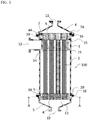
- FIG. 1 is a schematic longitudinal cross-sectional diagram of the hollow-fiber membrane module 100 of a first embodiment of the present invention.
- FIG. 2 is a cross-sectional diagram along line A-Ain FIG. 1
- FIG. 3 is a side view of the protective member and the second potting part in FIG. 1 .
- the hollow-fiber membrane module 100 includes a hollow-fiber membrane bundle 2 in which a plurality of hollow-fiber membranes 1 are bundled into a cylindrical shape in a first potting part 6 and a second potting part 8, a housing enclosing the hollow-fiber membrane bundle 2, and a protective member 9 contacting with the outer surface of the second potting part 8 and continuously covering the outer surface.
- the protective member 9 has a notched part 9A.
- the first end part that is an end part on the first potting part 6 side is in an open state.
- the second end part that is an end part on the second potting part 8 side is in a state of being sealed by the second potting part 8.
- the housing is composed of a hollow cylindrical case 3, and a first cap 4 and a second cap 5 liquid-tightly and air-tightly fixed by a gasket 16 to both end parts of the cylindrical case 3.
- the first cap 4 has a filtrate outlet 11, and the second cap 5 has a raw water inlet 10.
- the cylindrical case 3 has a raw water outlet 12 nearer the first cap 4 in its lateral part.
- flange parts 3A and 3B are formed over the entire circumference. Furthermore, in the cylindrical case 3-side end part of the first cap 4, a step part 4Ais formed over the entire circumference so that when the cylindrical case 3 and the fist cap 4 are fixed, a groove can be formed between the flange part 3A and the first cap 4.
- the first potting part 6 is enclosed in a cylindrical flow-regulating cylinder 7.
- a flange part 7A is formed over the entire circumference.
- the flange part 7A is inserted into a groove (fixing part) between the flange part 3A and the fist cap 4, and the first potting part 6 is thereby liquid-tightly and air-tightly fixed in one end part of the cylindrical case 3.
- a plurality of slit-like flow-regulating holes 14 extending in the longitudinal direction of the hollow-fiber membrane bundle are formed so as to prevent drift around the raw water outlet 12.
- a gap 21 is provided between the cylindrical case 3 and the flow-regulating cylinder 7.
- an O ring 15 is disposed as a sealing member to liquid-tightly and air-tightly partition both sides thereof.
- a through-hole 13 penetrating in the longitudinal direction of the hollow-fiber membrane bundle is formed in the second potting part 8, and a gap 20 is provided between the second potting part 8 and the housing.
- the protective member 9 contacts with the outer surface of the second potting part 8 and continuously covers the outer surface.
- FIG. 4 is a schematic longitudinal cross-sectional diagram of the hollow-fiber membrane module 101 of a second embodiment of the present invention.
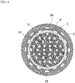
- FIG. 6 is a cross-sectional diagram along line A-A in FIG. 4 .
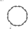
- the hollow-fiber membrane module 101 includes a ring 18 having a notch as illustrated in FIG. 5 , etc., in addition to the configuration of the first embodiment.
- the ring 18 is inserted, as a holding member, between a second holding groove 19 formed in the outer surface of the protective member 9 and a first holding groove 17 formed in the inner surface of the housing to face the second holding groove, and the protective member 9 is thereby held in the housing while maintaining an appropriate gap.
- a second holding groove 19 formed in the outer surface of the protective member 9 and a first holding groove 17 formed in the inner surface of the housing to face the second holding groove, and the protective member 9 is thereby held in the housing while maintaining an appropriate gap.
- the holding member is not limited to the above-exemplified ring, and the form thereof is not particularly limited as long as a gap allowing a fluid to move therethrough can be formed between the protective member and the housing.
- Raw water as a material to be filtered flows into the hollow-fiber membrane module 100 or 101 through a raw water inlet 10 of the second cap 5, and a part thereof permeates into the hollow part of the hollow-fiber membrane 1 and flows out to the outside of the hollow-fiber membrane module 100 or 101 through a filtrate outlet 11 of the first cap 4.
- the remaining raw water not permeated into the inside of the hollow-fiber membrane 1 is discharged to the outside of the hollow-fiber membrane module 100 or 101 through a raw water outlet 12.
- a method of performing filtration in this way by flowing a material to be filtered in the longitudinal direction of the hollow-fiber membrane is referred to as cross-flow filtration and is effective in preventing suspended substances, etc. in the raw water from depositing on the surface of the hollow-fiber membrane.
- the raw water outlet 12 is closed, dead-end filtration of filtering all the raw water can be performed, or when air is supplied from the raw water inlet 10, cleaning of the hollow-fiber membrane 1 by air scrubbing can also be performed.
- the second potting part 8 may move due to a material to be filtered, which is flowed in through the raw water inlet 10, and the hollow-fiber membrane 1 consequently may deform to cause damage to the hollow-fiber membrane 1. Therefore, as in the hollow-fiber membrane module of the second embodiment, the protective member is preferably held in a housing so as to suppress the movement of the second potting part 8.
- a holding member is preferably inserted between a holding groove formed in the outer surface of the protective member and a holding groove formed in the inner surface of the housing to face the holding groove above.
- the production method of the hollow-fiber membrane module of the present invention includes (1) a potting part-forming step of forming a potting part and thereby bundling a plurality of hollow-fiber membranes to obtain a hollow-fiber membrane bundle, and (2) a protective member-bonding step of bonding a protective member such that the protective member contacts with the outer surface of the potting part and continuously covers the outer surface.
- the potting part-forming step included in the production method of the hollow-fiber membrane module of the present invention is a step of forming a potting part so as to bundle a plurality of hollow-fiber membranes and thereby to obtain a hollow-fiber membrane bundle.
- the potting part is formed by filling spaces between hollow fibers with a potting agent containing a potting resin as a main component, which is a so-called adhesive.
- the potting agent is preferably subjected in advance to a defoaming treatment such as centrifugal defoaming or vacuum defoaming so as to reduce air bubbles, etc. in the inside thereof.
- a defoaming treatment such as centrifugal defoaming or vacuum defoaming so as to reduce air bubbles, etc. in the inside thereof.
- the shape of the obtained hollow-fiber membrane bundle is preferably a cylindrical shape that facilitates bundling.
- the protective member-bonding step included in the production method of the hollow-fiber membrane module of the present invention is a step of bonding a protective member such that the protective member contacts with the outer surface of the potting part and continuously covers the outer surface.
- the potting agent containing, as a main component, a potting resin such as epoxy resin, polyurethane resin or silicone resin undergoes curing shrinkage when changing from a liquid state to a solid state.
- a potting resin such as epoxy resin, polyurethane resin or silicone resin undergoes curing shrinkage, while a stress of pulling the protective member toward the potting agent side generates, the protective member cannot follow it, and the protective member is sometimes separated from the potting agent.
- the viscosity of the adhesive used for the bonding of the protective member is preferably from 500 to 30,000 mPa ⁇ s so as to obtain appropriate coating property while preventing dripping, etc.
- Raw water was flowed in through the raw water inlet of the hollow-fiber membrane module and flowed out or discharged (membrane surface linear velocity: 0.5 m/s) through the filtrate outlet at a flow rate of 300 L/hour and through the raw water outlet at a flow rate of 20 m 3 /hour, and this operation was continued for 100 hours. Thereafter, the hollow-fiber membrane module was disassembled, and the presence or absence of bending (buckling) of the hollow-fiber membrane and damage to the second potting part was visually confirmed.
- the hollow-fiber membrane module was heated with water vapor at 125°C for 1 hour and then disassembled such that the bonding interface can be observed, and the bonding area of the adhesive layer between the potting part and the protective member was visually observed to evaluate the presence or absence of separation.
- a hollow-fiber membrane module illustrated in FIG. 1 was prepared by cylindrically bundling 6,000 polyvinylidene fluoride hollow fiber membranes (thickness: 225 ⁇ m, outer diameter: 1,250 ⁇ m, percentage of hollowness: 41%) subjected to preliminary heating with water vapor at 125°C for 1 hour.
- the first potting part and the second potting part were molded by a static potting method using, as a potting agent, a mixture of a bisphenol A-type epoxy resin (JER828, produced by Mitsubishi Chemical Corporation), an aliphatic cyclic amine-based curing agent (4,4-methylenebis(cyclohexylamine), produced by Wako Pure Chemical Industries, Ltd.), and an aliphatic linear amine-based curing agent (diethylenetriamine, produced by Wako Pure Chemical Industries, Ltd.), which were previously preheated in a thermostat at 40°C and mixed to obtain a mass ratio of 100:22:12.
- a bisphenol A-type epoxy resin JER828, produced by Mitsubishi Chemical Corporation
- an aliphatic cyclic amine-based curing agent (4,4-methylenebis(cyclohexylamine), produced by Wako Pure Chemical Industries, Ltd.
- an aliphatic linear amine-based curing agent diethylenetriamine, produced by Wako Pure Chemical Industries, Ltd.
- Part of the surface of the second potting part was polished with abrasive paper #80 and then, two semicircular protective members (made of polysulfone) illustrated in FIG. 7 in which the thickness of the member in a direction perpendicular to the longitudinal direction of the hollow-fiber membrane bundle is 6 mm were made to contact therewith using the potting agent above as an adhesive.
- the protective member consisting of two protective members had two notched parts, and the degree of coverage thereof for L max was 99%.
- the width of the notched part in a direction perpendicular to the longitudinal direction of the hollow-fiber membrane bundle was 2.5 mm.
- the inner diameter of the cylindrical case (made of SUS316L) was 159.2 mm, and the gap between the second potting part and the housing was 0.5 mm or more.
- This hollow-fiber membrane module was evaluated for the adhesion between the potting part and the protective member, as a result, separation was not observed after heating with water vapor at 125°C.
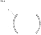
- a hollow-fiber membrane module was prepared in the same manner as in Example 1 except that the protective member was changed to those (made of polysulfone) illustrated in FIG. 8 in which the thickness of the member in a direction perpendicular to the longitudinal direction of the hollow-fiber membrane bundle is 6 mm.
- the protective member consisting of two protective members had two notched parts, and the degree of coverage thereof for L max was 50%.
- the width of the notched part in a direction perpendicular to the longitudinal direction of the hollow-fiber membrane bundle was 124.3 mm.
- This hollow-fiber membrane module was evaluated for the adhesion between the potting part and the protective member, as a result, separation was not observed after heating with water vapor at 125°C.
- a hollow-fiber membrane module illustrated in FIG. 4 was prepared by cylindrically bundling 6,000 polyvinylidene fluoride hollow fiber membranes (thickness: 225 ⁇ m, outer diameter: 1,250 ⁇ m, percentage of hollowness: 41%) subjected to preliminary heating with water vapor at 125°C for 1 hour.
- the first potting part and the second potting part were molded by a static potting method using, as a potting agent, a mixture of a bisphenol A-type epoxy resin (JER828, produced by Mitsubishi Chemical Corporation), an aliphatic cyclic amine-based curing agent (4,4-methylenebis(cyclohexylamine), produced by Wako Pure Chemical Industries, Ltd.), and an aliphatic linear amine-based curing agent (diethylenetriamine, produced by Wako Pure Chemical Industries, Ltd.), which were previously preheated in a thermostat at 40°C and mixed to obtain a mass ratio of 100:22:12.
- a bisphenol A-type epoxy resin JER828, produced by Mitsubishi Chemical Corporation
- an aliphatic cyclic amine-based curing agent (4,4-methylenebis(cyclohexylamine), produced by Wako Pure Chemical Industries, Ltd.
- an aliphatic linear amine-based curing agent diethylenetriamine, produced by Wako Pure Chemical Industries, Ltd.
- Part of the surface of the second potting part was polished with abrasive paper #80 and then, two semicircular protective members (made of polysulfone) illustrated in FIG. 9 in which the thickness of the member in a direction perpendicular to the longitudinal direction of the hollow-fiber membrane bundle is 6 mm were made to contact therewith using the potting agent above as an adhesive.
- the protective member consisting of two protective members had two notched parts, and the degree of coverage thereof for L max was 95%.
- the width of the notched part in a direction perpendicular to the longitudinal direction of the hollow-fiber membrane bundle was 12.4 mm.
- a groove as illustrated in FIG. 4 was formed in the outer surface of the second potting part, and the convex part of the protective member was made to contact with the groove in the outer surface of the second potting part.
- a ring having a notch was inserted between the holding groove formed in the outer surface of the protective member and the holding groove formed in the inner surface of the housing to face the holding groove in the outer surface of the protective member.
- the inner diameter of the cylindrical case (made of SUS316L) was 159.2 mm, and the gap between the second potting part and the housing was 0.5 mm or more.
- this hollow-fiber membrane module was evaluated for the adhesion between the potting part and the protective member, as a result, separation was not observed after heating with water vapor at 125°C.
- a hollow-fiber membrane module was prepared in the same manner as in Example 3 except that the protective member consisting of two protective members had two notched parts and the degree of coverage for L max of 99.8%, and the width of the notched part in a direction perpendicular to the longitudinal direction of the hollow-fiber membrane bundle was 0.5 mm.
- this hollow-fiber membrane module was evaluated for the adhesion between the potting part and the protective member, as a result, separation was not observed after heating with water vapor at 125°C.
- a hollow-fiber membrane module was prepared in the same manner as in Example 4 except that the protective member consisting of two protective members had two notched parts and the degree of coverage for L max of 20.0%, and the width of the notched part in a direction perpendicular to the longitudinal direction of the hollow-fiber membrane bundle was 200 mm.
- this hollow-fiber membrane module was evaluated for the adhesion between the potting part and the protective member, as a result, separation was not observed after heating with water vapor at 125°C.
- a hollow-fiber membrane module was prepared in the same manner as in Example 1 except that the static potting was performed after previously attaching a protective member in which the thickness of the member in a direction perpendicular to the longitudinal direction of a cylindrical hollow-fiber membrane bundle is 6 mm to a potting jig, and the degree of coverage for L max was 100% (having no notched part).
- this hollow-fiber membrane module was evaluated for the adhesion between the potting part and the protective member, as a result, separation was observed after heating with water vapor at 125°C.
Landscapes
- Chemical & Material Sciences (AREA)
- Chemical Kinetics & Catalysis (AREA)
- Engineering & Computer Science (AREA)
- Manufacturing & Machinery (AREA)
- Separation Using Semi-Permeable Membranes (AREA)
Abstract
Description
- The present invention relates to a hollow-fiber membrane module and a production method of a hollow-fiber membrane module.
- In recent years, a separation membrane such as a microfiltration membrane or an ultrafiltration membrane is utilized for a fluid separation process in various fields including food industry, medical treatment, biotechnology, water production, wastewater treatment, etc., because it contributes, for example, to energy saving, space saving, or product quality enhancement.
- Examples of the shape of the separation membrane include a flat membrane and a hollow-fiber membrane. As for the hollow-fiber membrane, a hollow-fiber membrane module, in which a housing encloses a hollow-fiber membrane cartridge in which a multitude of hollow-fiber membrane bundles are bound together at both ends in a potting part and a cylindrical protective member contacts with the outer surface of the potting part, is known (Patent Literature 1).
- Patent Literature 1: Japanese Patent No.
4,498,373 - However, in the conventional hollow-fiber membrane module in which a protective member contacts with the outer surface of a potting part, it is regarded as a problem that the protective member cannot smoothly follow the curing shrinkage of the potting resin or the expansion or shrinkage of the potting part during a heat treatment, etc. of the hollow-fiber membrane module and consequently, the protective member is separated from the potting part.
- Accordingly, an object of the present invention is to provide a hollow-fiber membrane module capable of suppressing separation between a potting part and a protective member.
- In order to attain the object above, the present invention provides a hollow-fiber membrane module including: a hollow-fiber membrane bundle including a plurality of hollow-fiber membranes bundled in a potting part; a housing enclosing the hollow-fiber membrane bundle; and a protective member contacting with an outer surface of the potting part and continuously covering the outer surface, in which the protective member has a notched part through which one end of the protective member communicates with another end in a longitudinal direction of the hollow-fiber membrane bundle. And the present invention provides a production method thereof.
- In the present invention, a hollow-fiber membrane module capable of preventing a potting part and a protective member from separating from each other due to curing shrinkage of the potting agent or heat treatment of the hollow-fiber membrane module can be provided.
-
- [
FIG. 1] FIG. 1 is a schematic longitudinal cross-sectional diagram of the hollow-fiber membrane module of a first embodiment of the present invention. - [
FIG. 2] FIG. 2 is a cross-sectional diagram along line A-A inFIG. 1 . - [
FIG. 3] FIG. 3 is a side view of the protective member and the second potting part inFIG. 1 . - [
FIG. 4] FIG. 4 is a schematic longitudinal cross-sectional diagram of the hollow-fiber membrane module of a second embodiment of the present invention. - [
FIG. 5] FIG. 5 is a schematic diagram of a ring having a notch. - [
FIG. 6] FIG. 6 is a cross-sectional diagram along line A-A inFIG. 4 . - [
FIG. 7] FIG. 7 is a schematic diagram illustrating one embodiment of the protective member. - [
FIG. 8] FIG. 8 is a schematic diagram illustrating one embodiment of the protective member. - [
FIG. 9] FIG. 9 is a schematic diagram illustrating one embodiment of the protective member. - The embodiments of the present invention are described in detail below by referring to the drawings, but the present invention is not limited by these embodiments in any way.
- The hollow-fiber membrane module of the present invention must include a hollow-fiber membrane bundle including a plurality of hollow-fiber membranes bundled in a potting part, a housing enclosing the hollow-fiber membrane bundle, and a protective member contacting with the outer surface of the potting part and continuously covering the outer surface.
- In the hollow-fiber membrane bundle included in the hollow-fiber membrane module of the present invention, a plurality of hollow-fiber membranes are bundled by at least one potting part.
- The "hollow-fiber membrane" constituting the hollow-fiber membrane bundle indicates a hollow fiber-shaped membrane composed of a polymer and having a separation function for liquid or gas.
- Examples of the polymer as a material of the hollow-fiber membrane include an olefin-based polymer such as polyethylene, ethylene-propylene copolymer, ethylene-ethyl acrylate copolymer, ethylene-vinyl acetate copolymer, ionomer, polypropylene or poly-4-methylpentene-1, a fluorine-containing polymer such as polyvinylidene fluoride, polytetrafluoroethylene, polychlorotrifluoroethylene, polyvinylidene fluoride, tetrafluoroethylene-ethylene copolymer or tetrafluoroethylene-perfluoroalkyl vinyl ether copolymer, a cellulose-based polymer such as cellulose acetate, a polyvinyl chloride, an acrylonitrile-based polymer, a silicone-based polymer, a polyamide, a polyimide, a polyethersulfone, a polysulfone, a polyphenylene oxide, a polyphenylene sulfide, a polyallylate, a polyether ether ketone, a polyether imide, a polycarbonate, a polyvinyl alcohol-based polymer, etc. In order to increase the heat resistance, physical strength and chemical durability of the obtained hollow-fiber membrane, a fluorine-containing polymer, a polyethersulfone, or a polysulfone is preferred.
- From the viewpoint of satisfying both the permeation performance and the physical strength, the thickness of the hollow-fiber membrane is preferably from 20 to 500 µm, more preferably from 30 to 500 µm, still more preferably from 40 to 500 µm.
- From the viewpoint of satisfying both the effective membrane area and the physical strength, the outer diameter of the hollow-fiber membrane is preferably from 100 to 2,000 µm, more preferably from 200 to 1,500 µm, still more preferably from 300 to 1,000 µm.
- In view of the balance between the pressure loss of a fluid flowing through the hollow part and the buckling pressure, the percentage of hollowness of the hollow-fiber membrane is preferably from 15 to 70%, more preferably from 20 to 65%, still more preferably from 25 to 60%. The outer diameter and percentage of hollowness of the hollow-fiber membrane can be adjusted by appropriately changing, for example, the shape of a discharge hole of a spinneret for producing the hollow fiber or the draft ratio represented by winding rate/discharge rate during production of the hollow fiber.
- The pore diameter or pore shape of the hollow-fiber membrane can be appropriately selected according to the separation target. The hollow-fiber membrane may be subjected, if desired, to a surface treatment such as organic solvent treatment, plasma discharge treatment, corona discharge treatment or ozone treatment. Furthermore, since a hot-water treatment or steam sterilization treatment sometimes causes thermal shrinkage of the hollow-fiber membrane, a hollow-fiber membrane subjected in advance to a preheating treatment may be used.
- The "potting part" for bundling a plurality of hollow-fiber membranes indicates a region in which spaces between hollow fibers bundled is filled with a potting agent containing a potting resin as a main component, which is a so-called adhesive.
- The potting resin serving as a main component of the potting agent is preferably an epoxy resin, a polyurethane resin, or a silicone resin, which are excellent in terms of adhesion to the hollow-fiber membrane, heat resistance and chemical durability. In addition, the potting agent may contain, other than the potting resin, for example, an additive such as silica, talc, mica, clay, calcium carbonate, glass or rubber. Furthermore, the potting agent may also contain, as a curing agent, an aliphatic cyclic amine-based curing agent or an aliphatic linear amine-based curing agent.
- The potting part is preferably formed in an end part of the hollow-fiber membrane bundle because of ease of forming and is more preferably formed in both end parts for more firmly binding a plurality of hollow-fiber membranes together. That is, it is more preferable for the hollow-fiber membrane bundle to be bundled at its both ends in potting parts.
- Examples of the method for filling a space between hollow-fiber membranes with a potting agent include a centrifugal potting method of infiltrating a potting agent by utilizing a centrifugal force, and a static potting method of infiltrating a potting agent by its natural flow. In addition, a potting resin may also be poured into a mold for cast molding and made to fill a space between hollow-fiber membranes. On this occasion, in order to prevent the potting part from deforming in an ex-post manner, the potting part may be molded by performing the filling with a potting agent and the curing shrinkage in a plurality of batches.
- Examples of the material of a housing included in the hollow-fiber membrane module of the present invention include a fluorine-based resin such as polytetrafluoroethylene or perfluoroalkoxy fluororesin, polysulfone, polyethersulfone, polycarbonate, polypropylene, polymethylpentene, polyphenylene sulfide, polyether ketone, polyvinyl chloride resin, ABS resin, stainless steel, and aluminum.
- The protective member included in the hollow-fiber membrane module of the present invention contacts with the outer surface of the potting part and continuously covers the outer surface. In addition, the protective member must have a notched part through which one end of the protective member in the longitudinal direction of the hollow-fiber membrane bundle communicates with another end.
- The "protective member" as used herein indicates a member formed of a material different from the material of the potting part to be contacted and continuously covered with the protective member.
- In addition, to say the protective member "contacts" with the outer surface of the potting part indicates that at least a part of the protective member is in contact with the outer surface of the potting part, directly or indirectly with the intervention of other component such as cured adhesive.
- Furthermore, to say the protective member "continuously covers the outer surface" of the potting part indicates that when assuming lines L, whose start point and end point coincide with each other, drawn by setting one point within the potting part on the surface of the potting part as a basis point and connecting, in a continuous manner, the points in a direction perpendicular to the longitudinal direction of the hollow-fiber membrane bundle and when regarding the longest line among the lines L as Lmax, one or plurality of protective members are arranged to cover 20% or more of the total length of the line Lmax. For example, in the case where the potting part is cylindrical having a perfect circular cross-section, the line Lmax corresponds to the circumference of the perfect circle. The degree of coverage for the line Lmax is preferably 20% or more, more preferably 40% or more, still more preferably 90% or more. In addition, the degree of coverage for the line Lmax is preferably less than 99.9%.
- The "notched part" of the protective member indicates a region where the outer surface of the potting part is exposed between one end part of a protective member in the longitudinal direction of the hollow-fiber membrane bundle and another end part. Note that the "another end part" may be another end part of the same protective member having the "one end part" or may be one end part of another protective member different from the protective member having the "one end part" above.
- To say "one end of the protective member communicates with another end" in the longitudinal direction of the hollow-fiber membrane bundle through the notched part of the protective member indicates a state where the notched part of the protective member, i.e., the region where the outer surface of the potting part is exposed, continues without a break between one end of the protective member in the longitudinal direction of the hollow-fiber membrane bundle and another end. In the case where the protective member continuously covering the outer surface has two or more notched parts, the "protective member continuously covering the outer surface" is composed of a plurality of protective members.
- The shape of the notched part, when observed from a direction perpendicular to the longitudinal direction of the hollow-fiber membrane bundle, may be linear or a shape including a curve or bent part.
- When the protective member has such a notched part, the protective member can smoothly follow the shrinkage or expansion of the potting part during curing shrinkage of the potting agent or heat treatment of the hollow-fiber membrane module, and contacting between the potting part and the protective member can be maintained, so that separation therebetween can be suppressed. In order for the protective member to be capable of more smoothly following the expansion or shrinkage of the potting part, the protective member preferably has a plurality of notched parts. The width of the notched part in a direction perpendicular to the longitudinal direction of the hollow-fiber membrane bundle is preferably 0.5 mm or more, more preferably 1 mm or more, still more preferably 3 mm or more.
- The ratio of the length of the protective member in the longitudinal direction of the hollow-fiber membrane bundle to the length of the potting part in the longitudinal direction of the hollow-fiber membrane bundle is preferably 10% or more so as to ensure the durability of the protective member.
- Examples of the material of the protective member include a fluorine-based resin such as polytetrafluoroethylene or perfluoroalkoxy fluororesin, polysulfone, polyethersulfone, polycarbonate, polypropylene, polymethylpentene, polyphenylene sulfide, polyether ketone, polyvinyl chloride resin, and ABS resin.
- Examples of the adhesive used for making the protective member contact with the outer surface of the potting part include an adhesive containing, as a main component, an epoxy resin or a polyurethane resin. In addition, the adhesive may contain, other than the adhesive, for example, an additive such as silica, talc, mica, clay, calcium carbonate, glass or rubber.
- Some embodiments of the hollow-fiber membrane module of the present invention are described in greater detail below by referring to the drawings.
-
FIG. 1 is a schematic longitudinal cross-sectional diagram of the hollow-fiber membrane module 100 of a first embodiment of the present invention.FIG. 2 is a cross-sectional diagram along line A-AinFIG. 1 , andFIG. 3 is a side view of the protective member and the second potting part inFIG. 1 . - The hollow-
fiber membrane module 100 includes a hollow-fiber membrane bundle 2 in which a plurality of hollow-fiber membranes 1 are bundled into a cylindrical shape in afirst potting part 6 and asecond potting part 8, a housing enclosing the hollow-fiber membrane bundle 2, and aprotective member 9 contacting with the outer surface of thesecond potting part 8 and continuously covering the outer surface. As illustrated inFIG. 2 andFIG. 3 , theprotective member 9 has a notchedpart 9A. - In all hollow-
fiber membranes 1, the first end part that is an end part on thefirst potting part 6 side is in an open state. On the other hand, in all hollow-fiber membranes 1, the second end part that is an end part on thesecond potting part 8 side is in a state of being sealed by thesecond potting part 8. - The housing is composed of a hollow
cylindrical case 3, and afirst cap 4 and asecond cap 5 liquid-tightly and air-tightly fixed by agasket 16 to both end parts of thecylindrical case 3. Thefirst cap 4 has afiltrate outlet 11, and thesecond cap 5 has araw water inlet 10. In addition, thecylindrical case 3 has araw water outlet 12 nearer thefirst cap 4 in its lateral part. - In both end parts of the
cylindrical case 3,flange parts first cap 4, a step part 4Ais formed over the entire circumference so that when thecylindrical case 3 and thefist cap 4 are fixed, a groove can be formed between theflange part 3A and thefirst cap 4. - The
first potting part 6 is enclosed in a cylindrical flow-regulatingcylinder 7. In one end part of the flow-regulatingcylinder 7, aflange part 7A is formed over the entire circumference. Theflange part 7A is inserted into a groove (fixing part) between theflange part 3A and thefist cap 4, and thefirst potting part 6 is thereby liquid-tightly and air-tightly fixed in one end part of thecylindrical case 3. - In the flow-regulating
cylinder 7, a plurality of slit-like flow-regulatingholes 14 extending in the longitudinal direction of the hollow-fiber membrane bundle are formed so as to prevent drift around theraw water outlet 12. In order to prevent steam drain stagnation during steam sterilization of the hollow-fiber membrane module 100, agap 21 is provided between thecylindrical case 3 and the flow-regulatingcylinder 7. - Between the flow-regulating
cylinder 7 fixing thefirst potting part 6 and the housing, anO ring 15 is disposed as a sealing member to liquid-tightly and air-tightly partition both sides thereof. - A through-
hole 13 penetrating in the longitudinal direction of the hollow-fiber membrane bundle is formed in thesecond potting part 8, and agap 20 is provided between thesecond potting part 8 and the housing. - The
protective member 9 contacts with the outer surface of thesecond potting part 8 and continuously covers the outer surface. -
FIG. 4 is a schematic longitudinal cross-sectional diagram of the hollow-fiber membrane module 101 of a second embodiment of the present invention. In addition,FIG. 6 is a cross-sectional diagram along line A-A inFIG. 4 . The hollow-fiber membrane module 101 includes aring 18 having a notch as illustrated inFIG. 5 , etc., in addition to the configuration of the first embodiment. - The
ring 18 is inserted, as a holding member, between asecond holding groove 19 formed in the outer surface of theprotective member 9 and afirst holding groove 17 formed in the inner surface of the housing to face the second holding groove, and theprotective member 9 is thereby held in the housing while maintaining an appropriate gap. In this way, an embodiment where the protective member contacts with the outer surface of the second potting part, and the inner surface of the housing and the protective member are locked with each other by the holding member, is preferred. - The holding member is not limited to the above-exemplified ring, and the form thereof is not particularly limited as long as a gap allowing a fluid to move therethrough can be formed between the protective member and the housing.
- One example of the filtration operation (water treatment) using the hollow-fiber membrane module of the present invention is described below.
- Raw water as a material to be filtered flows into the hollow-
fiber membrane module raw water inlet 10 of thesecond cap 5, and a part thereof permeates into the hollow part of the hollow-fiber membrane 1 and flows out to the outside of the hollow-fiber membrane module filtrate outlet 11 of thefirst cap 4. The remaining raw water not permeated into the inside of the hollow-fiber membrane 1 is discharged to the outside of the hollow-fiber membrane module raw water outlet 12. - A method of performing filtration in this way by flowing a material to be filtered in the longitudinal direction of the hollow-fiber membrane is referred to as cross-flow filtration and is effective in preventing suspended substances, etc. in the raw water from depositing on the surface of the hollow-fiber membrane. When the
raw water outlet 12 is closed, dead-end filtration of filtering all the raw water can be performed, or when air is supplied from theraw water inlet 10, cleaning of the hollow-fiber membrane 1 by air scrubbing can also be performed. In the cross-flow filtration or air scrubbing, thesecond potting part 8 may move due to a material to be filtered, which is flowed in through theraw water inlet 10, and the hollow-fiber membrane 1 consequently may deform to cause damage to the hollow-fiber membrane 1. Therefore, as in the hollow-fiber membrane module of the second embodiment, the protective member is preferably held in a housing so as to suppress the movement of thesecond potting part 8. - Namely, in the hollow-fiber membrane module of the present invention, a holding member is preferably inserted between a holding groove formed in the outer surface of the protective member and a holding groove formed in the inner surface of the housing to face the holding groove above.
- The production method of the hollow-fiber membrane module of the present invention includes (1) a potting part-forming step of forming a potting part and thereby bundling a plurality of hollow-fiber membranes to obtain a hollow-fiber membrane bundle, and (2) a protective member-bonding step of bonding a protective member such that the protective member contacts with the outer surface of the potting part and continuously covers the outer surface.
- The potting part-forming step included in the production method of the hollow-fiber membrane module of the present invention is a step of forming a potting part so as to bundle a plurality of hollow-fiber membranes and thereby to obtain a hollow-fiber membrane bundle.
- The potting part is formed by filling spaces between hollow fibers with a potting agent containing a potting resin as a main component, which is a so-called adhesive.
- The potting agent is preferably subjected in advance to a defoaming treatment such as centrifugal defoaming or vacuum defoaming so as to reduce air bubbles, etc. in the inside thereof.
- The shape of the obtained hollow-fiber membrane bundle is preferably a cylindrical shape that facilitates bundling.
- The protective member-bonding step included in the production method of the hollow-fiber membrane module of the present invention is a step of bonding a protective member such that the protective member contacts with the outer surface of the potting part and continuously covers the outer surface.
- The potting agent containing, as a main component, a potting resin such as epoxy resin, polyurethane resin or silicone resin undergoes curing shrinkage when changing from a liquid state to a solid state. When a liquid-state potting agent with which the protective member contacts undergoes curing shrinkage, while a stress of pulling the protective member toward the potting agent side generates, the protective member cannot follow it, and the protective member is sometimes separated from the potting agent.
- On the other hand, when the potting agent is sufficiently cured and shrunk in the potting part-forming step (1) and thereafter, the protective member is bonded in the protective member-bonding step (2), separation of the protective member due to curing shrinkage of the liquid-state potting agent can be suppressed. In order to promote curing shrinkage of the liquid-state potting agent and increase the strength of the potting part after curing shrinkage, it is preferable to perform a heat treatment subsequently to the potting part-forming step (1).
- The viscosity of the adhesive used for the bonding of the protective member is preferably from 500 to 30,000 mPa·s so as to obtain appropriate coating property while preventing dripping, etc.
- Furthermore, in order to more enhance the adhesion of the protective member to the outer surface of the potting part, it is also preferable to previously polish the outer surface of the potting part with sandpaper, etc. and thereby provide fine irregularities.
- Raw water was flowed in through the raw water inlet of the hollow-fiber membrane module and flowed out or discharged (membrane surface linear velocity: 0.5 m/s) through the filtrate outlet at a flow rate of 300 L/hour and through the raw water outlet at a flow rate of 20 m3/hour, and this operation was continued for 100 hours. Thereafter, the hollow-fiber membrane module was disassembled, and the presence or absence of bending (buckling) of the hollow-fiber membrane and damage to the second potting part was visually confirmed.
- The hollow-fiber membrane module was heated with water vapor at 125°C for 1 hour and then disassembled such that the bonding interface can be observed, and the bonding area of the adhesive layer between the potting part and the protective member was visually observed to evaluate the presence or absence of separation.
- A hollow-fiber membrane module illustrated in
FIG. 1 was prepared by cylindrically bundling 6,000 polyvinylidene fluoride hollow fiber membranes (thickness: 225 µm, outer diameter: 1,250 µm, percentage of hollowness: 41%) subjected to preliminary heating with water vapor at 125°C for 1 hour. The first potting part and the second potting part were molded by a static potting method using, as a potting agent, a mixture of a bisphenol A-type epoxy resin (JER828, produced by Mitsubishi Chemical Corporation), an aliphatic cyclic amine-based curing agent (4,4-methylenebis(cyclohexylamine), produced by Wako Pure Chemical Industries, Ltd.), and an aliphatic linear amine-based curing agent (diethylenetriamine, produced by Wako Pure Chemical Industries, Ltd.), which were previously preheated in a thermostat at 40°C and mixed to obtain a mass ratio of 100:22:12. Part of the surface of the second potting part was polished with abrasive paper #80 and then, two semicircular protective members (made of polysulfone) illustrated inFIG. 7 in which the thickness of the member in a direction perpendicular to the longitudinal direction of the hollow-fiber membrane bundle is 6 mm were made to contact therewith using the potting agent above as an adhesive. The protective member consisting of two protective members had two notched parts, and the degree of coverage thereof for Lmax was 99%. The width of the notched part in a direction perpendicular to the longitudinal direction of the hollow-fiber membrane bundle was 2.5 mm. - The inner diameter of the cylindrical case (made of SUS316L) was 159.2 mm, and the gap between the second potting part and the housing was 0.5 mm or more.
- This hollow-fiber membrane module was evaluated for the adhesion between the potting part and the protective member, as a result, separation was not observed after heating with water vapor at 125°C.
- A hollow-fiber membrane module was prepared in the same manner as in Example 1 except that the protective member was changed to those (made of polysulfone) illustrated in
FIG. 8 in which the thickness of the member in a direction perpendicular to the longitudinal direction of the hollow-fiber membrane bundle is 6 mm. The protective member consisting of two protective members had two notched parts, and the degree of coverage thereof for Lmax was 50%. The width of the notched part in a direction perpendicular to the longitudinal direction of the hollow-fiber membrane bundle was 124.3 mm. - This hollow-fiber membrane module was evaluated for the adhesion between the potting part and the protective member, as a result, separation was not observed after heating with water vapor at 125°C.
- A hollow-fiber membrane module illustrated in
FIG. 4 was prepared by cylindrically bundling 6,000 polyvinylidene fluoride hollow fiber membranes (thickness: 225 µm, outer diameter: 1,250 µm, percentage of hollowness: 41%) subjected to preliminary heating with water vapor at 125°C for 1 hour. The first potting part and the second potting part were molded by a static potting method using, as a potting agent, a mixture of a bisphenol A-type epoxy resin (JER828, produced by Mitsubishi Chemical Corporation), an aliphatic cyclic amine-based curing agent (4,4-methylenebis(cyclohexylamine), produced by Wako Pure Chemical Industries, Ltd.), and an aliphatic linear amine-based curing agent (diethylenetriamine, produced by Wako Pure Chemical Industries, Ltd.), which were previously preheated in a thermostat at 40°C and mixed to obtain a mass ratio of 100:22:12. Part of the surface of the second potting part was polished with abrasive paper #80 and then, two semicircular protective members (made of polysulfone) illustrated inFIG. 9 in which the thickness of the member in a direction perpendicular to the longitudinal direction of the hollow-fiber membrane bundle is 6 mm were made to contact therewith using the potting agent above as an adhesive. The protective member consisting of two protective members had two notched parts, and the degree of coverage thereof for Lmax was 95%. The width of the notched part in a direction perpendicular to the longitudinal direction of the hollow-fiber membrane bundle was 12.4 mm. A groove as illustrated inFIG. 4 was formed in the outer surface of the second potting part, and the convex part of the protective member was made to contact with the groove in the outer surface of the second potting part. - A ring having a notch was inserted between the holding groove formed in the outer surface of the protective member and the holding groove formed in the inner surface of the housing to face the holding groove in the outer surface of the protective member.
- The inner diameter of the cylindrical case (made of SUS316L) was 159.2 mm, and the gap between the second potting part and the housing was 0.5 mm or more.
- With respect to this hollow-fiber membrane module, a cross-flow filtration test was conducted, as a result, neither damage to the second potting part and the protective member nor buckling of the hollow-fiber membrane was observed.
- In addition, this hollow-fiber membrane module was evaluated for the adhesion between the potting part and the protective member, as a result, separation was not observed after heating with water vapor at 125°C.
- A hollow-fiber membrane module was prepared in the same manner as in Example 3 except that the protective member consisting of two protective members had two notched parts and the degree of coverage for Lmax of 99.8%, and the width of the notched part in a direction perpendicular to the longitudinal direction of the hollow-fiber membrane bundle was 0.5 mm.
- With respect to this hollow-fiber membrane module, a cross-flow filtration test was conducted, as a result, neither damage to the second potting part and the protective member nor buckling of the hollow-fiber membrane was observed.
- In addition, this hollow-fiber membrane module was evaluated for the adhesion between the potting part and the protective member, as a result, separation was not observed after heating with water vapor at 125°C.
- A hollow-fiber membrane module was prepared in the same manner as in Example 4 except that the protective member consisting of two protective members had two notched parts and the degree of coverage for Lmax of 20.0%, and the width of the notched part in a direction perpendicular to the longitudinal direction of the hollow-fiber membrane bundle was 200 mm.
- With respect to this hollow-fiber membrane module, a cross-flow filtration test was conducted, as a result, neither damage to the second potting part and the protective member nor buckling of the hollow-fiber membrane was observed.
- In addition, this hollow-fiber membrane module was evaluated for the adhesion between the potting part and the protective member, as a result, separation was not observed after heating with water vapor at 125°C.
- A hollow-fiber membrane module was prepared in the same manner as in Example 1 except that the static potting was performed after previously attaching a protective member in which the thickness of the member in a direction perpendicular to the longitudinal direction of a cylindrical hollow-fiber membrane bundle is 6 mm to a potting jig, and the degree of coverage for Lmax was 100% (having no notched part).
- With respect to this hollow-fiber membrane module, a cross-flow filtration test was conducted, as a result, damage to the protective member was observed. In addition, damage due to buckling of the hollow-fiber membrane was recognized.
- In addition, this hollow-fiber membrane module was evaluated for the adhesion between the potting part and the protective member, as a result, separation was observed after heating with water vapor at 125°C.
- While the present invention has been described in detail and with reference to specific embodiments thereof, it will be apparent to one skilled in the art that various changes and modifications can be made therein without departing from the aim and scope of the invention. This application is based on Japanese Patent Application (Japanese Patent Application No.
2018-141044) filed on July 27, 2018 -
- 100
- Hollow-fiber membrane module
- 101
- Hollow-fiber membrane module
- 1
- Hollow-fiber membrane
- 2
- Hollow-fiber membrane bundle
- 3
- Cylindrical case
- 3A
- Flange part
- 3B
- Flange part
- 4
- First cap
- 4A
- Step part
- 5
- Second cap
- 6
- First potting part
- 7
- Flow-regulating cylinder
- 7A
- Flange part
- 8
- Second potting part
- 9
- Protective member
- 9A
- Notched part
- 10
- Raw water inlet
- 11
- Filtrate outlet
- 12
- Raw water outlet
- 13
- Through-hole
- 14
- Flow-regulating hole
- 15
- O-ring
- 16
- Gasket
- 17
- First holding groove
- 18
- Ring
- 19
- Second holding groove
- 20
- Gap
- 21
- Gap
Claims (7)
- A hollow-fiber membrane module comprising:a hollow-fiber membrane bundle comprising a plurality of hollow-fiber membranes bundled in a potting part;a housing enclosing the hollow-fiber membrane bundle; anda protective member contacting with an outer surface of the potting part and continuously covering the outer surface,wherein the protective member has a notched part through which one end of the protective member communicates with another end in a longitudinal direction of the hollow-fiber membrane bundle.
- The hollow-fiber membrane module according to claim 1, wherein the hollow-fiber membrane bundle is bundled at its both ends in the potting parts.
- The hollow-fiber membrane module according to claim 1 or 2, wherein the protective member has a plurality of notched parts.
- The hollow-fiber membrane module according to any one of claims 1 to 3, wherein one protective member or a plurality of protective members are arranged to cover 20% or more and less than 99.9% of a total length of a line Lmax, when assuming that lines L, whose start point and end point coincide with each other, are drawn by setting one point within the potting part as a basis point and connecting, in a continuous manner, points in a direction perpendicular to the longitudinal direction of the hollow-fiber membrane bundle, and regarding the longest line among the lines L as the Lmax.
- The hollow-fiber membrane module according to any one of claims 1 to 4, wherein the notched part of the protective member has a width of 0.5 mm or more in the direction perpendicular to the longitudinal direction of the hollow-fiber membrane bundle.
- The hollow-fiber membrane module according to any one of claims 1 to 5, wherein the protective member contacts with an outer surface of a second potting part and an inner surface of the housing and the protective member are locked with each other by a holding member.
- A production method of the hollow-fiber membrane module according to any one of claims 1 to 6, the method comprising:a potting part-forming step of forming the potting part and thereby bundling the plurality of hollow-fiber membranes to obtain the hollow-fiber membrane bundle; anda protective member-bonding step of bonding the protective member such that the protective member contacts with the outer surface of the potting part and continuously covers the outer surface.
Applications Claiming Priority (2)
| Application Number | Priority Date | Filing Date | Title |
|---|---|---|---|
| JP2018141044 | 2018-07-27 | ||
| PCT/JP2019/029522 WO2020022506A1 (en) | 2018-07-27 | 2019-07-26 | Hollow fibre membrane module and method for manufacturing hollow fibre membrane module |
Publications (3)
| Publication Number | Publication Date |
|---|---|
| EP3831469A1 true EP3831469A1 (en) | 2021-06-09 |
| EP3831469A4 EP3831469A4 (en) | 2022-04-27 |
| EP3831469B1 EP3831469B1 (en) | 2024-11-06 |
Family
ID=69182082
Family Applications (1)
| Application Number | Title | Priority Date | Filing Date |
|---|---|---|---|
| EP19840994.8A Active EP3831469B1 (en) | 2018-07-27 | 2019-07-26 | Hollow fibre membrane module and method for manufacturing hollow fibre membrane module |
Country Status (7)
| Country | Link |
|---|---|
| US (1) | US11958017B2 (en) |
| EP (1) | EP3831469B1 (en) |
| JP (1) | JP6780785B2 (en) |
| KR (1) | KR102717378B1 (en) |
| CN (1) | CN112469495B (en) |
| HU (1) | HUE069555T2 (en) |
| WO (1) | WO2020022506A1 (en) |
Families Citing this family (4)
| Publication number | Priority date | Publication date | Assignee | Title |
|---|---|---|---|---|
| KR102577689B1 (en) * | 2020-05-22 | 2023-09-12 | 코오롱인더스트리 주식회사 | Gasket assembly and fuel cell humidifier comprising it |
| KR102755443B1 (en) | 2021-02-04 | 2025-01-21 | 코오롱인더스트리 주식회사 | Gasket assembly and fuel cell membrane humidifier comprising it |
| KR20220112451A (en) * | 2021-02-04 | 2022-08-11 | 코오롱인더스트리 주식회사 | Gasket assembly and fuel cell membrane humidifier comprising it |
| US12502640B1 (en) | 2025-07-15 | 2025-12-23 | Avanpore LLC | Apparatus and method for purification of gas mixtures |
Family Cites Families (16)
| Publication number | Priority date | Publication date | Assignee | Title |
|---|---|---|---|---|
| JPS51106245U (en) * | 1975-02-21 | 1976-08-25 | ||
| JPH06296834A (en) | 1993-04-20 | 1994-10-25 | Kanegafuchi Chem Ind Co Ltd | Hollow fiber filter |
| KR100523778B1 (en) | 2000-07-10 | 2005-10-27 | 아사히 가세이 가부시키가이샤 | Hollow fiber membrane cartridge, and hollow fiber membrane module and tank type filtration apparatus which use the cartridge |
| JP4498373B2 (en) | 2000-07-10 | 2010-07-07 | 旭化成ケミカルズ株式会社 | Hollow fiber membrane cartridge, and hollow fiber membrane module and tank type filtration device using the same |
| ATE403488T1 (en) | 2001-03-06 | 2008-08-15 | Asahi Kasei Chemicals Corp | METHOD FOR PRODUCING HOLLOW FIBER MEMBRANES |
| JP4993901B2 (en) | 2005-11-29 | 2012-08-08 | 水ing株式会社 | Hollow fiber membrane module |
| JP2013099703A (en) | 2010-02-25 | 2013-05-23 | Asahi Kasei Chemicals Corp | Header member, membrane module and method for producing membrane module |
| JP5845989B2 (en) | 2011-03-18 | 2016-01-20 | 新日鐵住金株式会社 | Welding method of heat-processed steel sheet |
| JP2012210553A (en) * | 2011-03-30 | 2012-11-01 | Toray Ind Inc | Hollow fiber membrane module |
| JPWO2013146080A1 (en) * | 2012-03-30 | 2015-12-10 | 東レ株式会社 | Hollow fiber membrane module and manufacturing method thereof |
| US9227160B2 (en) | 2013-01-31 | 2016-01-05 | The Boeing Company | Gas separation modules and methods for forming |
| CN105142764B (en) | 2013-04-25 | 2018-09-11 | 东丽株式会社 | Cartridge type hollow fiber film assembly |
| MY181402A (en) | 2013-09-30 | 2020-12-21 | Toray Industries | Cartridge-type hollow fiber membrane module and method for manufacturing cartridge-type hollow fiber membrane module |
| AU2014371714B2 (en) | 2013-12-27 | 2019-04-11 | Toray Industries, Inc. | Hollow-fiber membrane module |
| DE102015015149B3 (en) | 2015-11-25 | 2017-01-26 | Serumwerk Bernburg Ag | A hollow fiber membrane filtration apparatus and method of making the same |
| JP6788872B2 (en) | 2017-02-27 | 2020-11-25 | パナソニックIpマネジメント株式会社 | Fluorescent material and light emitting device |
-
2019
- 2019-07-26 KR KR1020217002207A patent/KR102717378B1/en active Active
- 2019-07-26 US US17/263,380 patent/US11958017B2/en active Active
- 2019-07-26 JP JP2019541389A patent/JP6780785B2/en active Active
- 2019-07-26 EP EP19840994.8A patent/EP3831469B1/en active Active
- 2019-07-26 HU HUE19840994A patent/HUE069555T2/en unknown
- 2019-07-26 WO PCT/JP2019/029522 patent/WO2020022506A1/en not_active Ceased
- 2019-07-26 CN CN201980050105.9A patent/CN112469495B/en active Active
Also Published As
| Publication number | Publication date |
|---|---|
| CN112469495A (en) | 2021-03-09 |
| CN112469495B (en) | 2023-06-27 |
| JP6780785B2 (en) | 2020-11-04 |
| EP3831469B1 (en) | 2024-11-06 |
| KR102717378B1 (en) | 2024-10-16 |
| KR20210038550A (en) | 2021-04-07 |
| HUE069555T2 (en) | 2025-03-28 |
| EP3831469A4 (en) | 2022-04-27 |
| WO2020022506A1 (en) | 2020-01-30 |
| US20210316253A1 (en) | 2021-10-14 |
| US11958017B2 (en) | 2024-04-16 |
| JPWO2020022506A1 (en) | 2020-09-17 |
Similar Documents
| Publication | Publication Date | Title |
|---|---|---|
| EP3831469B1 (en) | Hollow fibre membrane module and method for manufacturing hollow fibre membrane module | |
| CN105473211B (en) | Cartridge type hollow fiber membrane module and manufacturing method of cartridge type hollow fiber membrane module | |
| CN105142764B (en) | Cartridge type hollow fiber film assembly | |
| CN111514759B (en) | Hollow fiber membrane module and method for manufacturing hollow fiber membrane module | |
| KR20180103922A (en) | Manufacturing method of hollow fiber membrane module and hollow fiber membrane module | |
| TW201347836A (en) | Hollow fiber membrane module and manufacturing method of hollow fiber membrane module | |
| CN110290856B (en) | Hollow fiber membrane module and filtration method | |
| US20180250853A1 (en) | Membrane Potting Methods | |
| WO2013047775A1 (en) | Method for hydrophilizing hollow-fiber membrane module | |
| JP5810094B2 (en) | Method for making a hollow fiber filtration device surrounded by two thermoplastic parts | |
| KR101902458B1 (en) | Hollowfiber Membrane Moldule | |
| JP3070997B2 (en) | Membrane separation module and method of manufacturing the same | |
| CN115605284A (en) | Method for manufacturing cylindrical hollow fiber membrane module | |
| JPH04247223A (en) | Hollow-fiber membrane module | |
| WO2024247626A1 (en) | Manufacturing method and manufacturing device for hollow fiber membrane module | |
| JPH0557155A (en) | Production of hollow fiber membrane separation module and said module | |
| JP2025148946A (en) | Hollow fiber membrane module, operation method of hollow fiber membrane module, and manufacturing method of hollow fiber membrane module | |
| JP2002066264A (en) | Filtration module |
Legal Events
| Date | Code | Title | Description |
|---|---|---|---|
| STAA | Information on the status of an ep patent application or granted ep patent |
Free format text: STATUS: THE INTERNATIONAL PUBLICATION HAS BEEN MADE |
|
| PUAI | Public reference made under article 153(3) epc to a published international application that has entered the european phase |
Free format text: ORIGINAL CODE: 0009012 |
|
| STAA | Information on the status of an ep patent application or granted ep patent |
Free format text: STATUS: REQUEST FOR EXAMINATION WAS MADE |
|
| 17P | Request for examination filed |
Effective date: 20210125 |
|
| AK | Designated contracting states |
Kind code of ref document: A1 Designated state(s): AL AT BE BG CH CY CZ DE DK EE ES FI FR GB GR HR HU IE IS IT LI LT LU LV MC MK MT NL NO PL PT RO RS SE SI SK SM TR |
|
| DAV | Request for validation of the european patent (deleted) | ||
| DAX | Request for extension of the european patent (deleted) | ||
| A4 | Supplementary search report drawn up and despatched |
Effective date: 20220330 |
|
| RIC1 | Information provided on ipc code assigned before grant |
Ipc: B01D 63/00 20060101ALI20220324BHEP Ipc: B01D 69/02 20060101AFI20220324BHEP |
|
| GRAP | Despatch of communication of intention to grant a patent |
Free format text: ORIGINAL CODE: EPIDOSNIGR1 |
|
| STAA | Information on the status of an ep patent application or granted ep patent |
Free format text: STATUS: GRANT OF PATENT IS INTENDED |
|
| INTG | Intention to grant announced |
Effective date: 20240710 |
|
| GRAS | Grant fee paid |
Free format text: ORIGINAL CODE: EPIDOSNIGR3 |
|
| GRAA | (expected) grant |
Free format text: ORIGINAL CODE: 0009210 |
|
| STAA | Information on the status of an ep patent application or granted ep patent |
Free format text: STATUS: THE PATENT HAS BEEN GRANTED |
|
| AK | Designated contracting states |
Kind code of ref document: B1 Designated state(s): AL AT BE BG CH CY CZ DE DK EE ES FI FR GB GR HR HU IE IS IT LI LT LU LV MC MK MT NL NO PL PT RO RS SE SI SK SM TR |
|
| REG | Reference to a national code |
Ref country code: GB Ref legal event code: FG4D |
|
| REG | Reference to a national code |
Ref country code: CH Ref legal event code: EP |
|
| REG | Reference to a national code |
Ref country code: DE Ref legal event code: R096 Ref document number: 602019061642 Country of ref document: DE |
|
| REG | Reference to a national code |
Ref country code: IE Ref legal event code: FG4D Ref country code: NL Ref legal event code: FP |
|
| P01 | Opt-out of the competence of the unified patent court (upc) registered |
Free format text: CASE NUMBER: APP_62056/2024 Effective date: 20241120 |
|
| REG | Reference to a national code |
Ref country code: LT Ref legal event code: MG9D |
|
| REG | Reference to a national code |
Ref country code: HU Ref legal event code: AG4A Ref document number: E069555 Country of ref document: HU |
|
| PG25 | Lapsed in a contracting state [announced via postgrant information from national office to epo] |
Ref country code: HR Free format text: LAPSE BECAUSE OF FAILURE TO SUBMIT A TRANSLATION OF THE DESCRIPTION OR TO PAY THE FEE WITHIN THE PRESCRIBED TIME-LIMIT Effective date: 20241106 Ref country code: PT Free format text: LAPSE BECAUSE OF FAILURE TO SUBMIT A TRANSLATION OF THE DESCRIPTION OR TO PAY THE FEE WITHIN THE PRESCRIBED TIME-LIMIT Effective date: 20250306 Ref country code: IS Free format text: LAPSE BECAUSE OF FAILURE TO SUBMIT A TRANSLATION OF THE DESCRIPTION OR TO PAY THE FEE WITHIN THE PRESCRIBED TIME-LIMIT Effective date: 20250306 |
|
| PG25 | Lapsed in a contracting state [announced via postgrant information from national office to epo] |
Ref country code: FI Free format text: LAPSE BECAUSE OF FAILURE TO SUBMIT A TRANSLATION OF THE DESCRIPTION OR TO PAY THE FEE WITHIN THE PRESCRIBED TIME-LIMIT Effective date: 20241106 |
|
| REG | Reference to a national code |
Ref country code: AT Ref legal event code: MK05 Ref document number: 1738762 Country of ref document: AT Kind code of ref document: T Effective date: 20241106 |
|
| PG25 | Lapsed in a contracting state [announced via postgrant information from national office to epo] |
Ref country code: BG Free format text: LAPSE BECAUSE OF FAILURE TO SUBMIT A TRANSLATION OF THE DESCRIPTION OR TO PAY THE FEE WITHIN THE PRESCRIBED TIME-LIMIT Effective date: 20241106 |
|
| PG25 | Lapsed in a contracting state [announced via postgrant information from national office to epo] |
Ref country code: ES Free format text: LAPSE BECAUSE OF FAILURE TO SUBMIT A TRANSLATION OF THE DESCRIPTION OR TO PAY THE FEE WITHIN THE PRESCRIBED TIME-LIMIT Effective date: 20241106 |
|
| PG25 | Lapsed in a contracting state [announced via postgrant information from national office to epo] |
Ref country code: NO Free format text: LAPSE BECAUSE OF FAILURE TO SUBMIT A TRANSLATION OF THE DESCRIPTION OR TO PAY THE FEE WITHIN THE PRESCRIBED TIME-LIMIT Effective date: 20250206 |
|
| PG25 | Lapsed in a contracting state [announced via postgrant information from national office to epo] |
Ref country code: LV Free format text: LAPSE BECAUSE OF FAILURE TO SUBMIT A TRANSLATION OF THE DESCRIPTION OR TO PAY THE FEE WITHIN THE PRESCRIBED TIME-LIMIT Effective date: 20241106 Ref country code: GR Free format text: LAPSE BECAUSE OF FAILURE TO SUBMIT A TRANSLATION OF THE DESCRIPTION OR TO PAY THE FEE WITHIN THE PRESCRIBED TIME-LIMIT Effective date: 20250207 Ref country code: AT Free format text: LAPSE BECAUSE OF FAILURE TO SUBMIT A TRANSLATION OF THE DESCRIPTION OR TO PAY THE FEE WITHIN THE PRESCRIBED TIME-LIMIT Effective date: 20241106 |
|
| PG25 | Lapsed in a contracting state [announced via postgrant information from national office to epo] |
Ref country code: PL Free format text: LAPSE BECAUSE OF FAILURE TO SUBMIT A TRANSLATION OF THE DESCRIPTION OR TO PAY THE FEE WITHIN THE PRESCRIBED TIME-LIMIT Effective date: 20241106 |
|
| PG25 | Lapsed in a contracting state [announced via postgrant information from national office to epo] |
Ref country code: RS Free format text: LAPSE BECAUSE OF FAILURE TO SUBMIT A TRANSLATION OF THE DESCRIPTION OR TO PAY THE FEE WITHIN THE PRESCRIBED TIME-LIMIT Effective date: 20250206 |
|
| PG25 | Lapsed in a contracting state [announced via postgrant information from national office to epo] |
Ref country code: SM Free format text: LAPSE BECAUSE OF FAILURE TO SUBMIT A TRANSLATION OF THE DESCRIPTION OR TO PAY THE FEE WITHIN THE PRESCRIBED TIME-LIMIT Effective date: 20241106 |
|
| PG25 | Lapsed in a contracting state [announced via postgrant information from national office to epo] |
Ref country code: DK Free format text: LAPSE BECAUSE OF FAILURE TO SUBMIT A TRANSLATION OF THE DESCRIPTION OR TO PAY THE FEE WITHIN THE PRESCRIBED TIME-LIMIT Effective date: 20241106 |
|
| PG25 | Lapsed in a contracting state [announced via postgrant information from national office to epo] |
Ref country code: EE Free format text: LAPSE BECAUSE OF FAILURE TO SUBMIT A TRANSLATION OF THE DESCRIPTION OR TO PAY THE FEE WITHIN THE PRESCRIBED TIME-LIMIT Effective date: 20241106 |
|
| PG25 | Lapsed in a contracting state [announced via postgrant information from national office to epo] |
Ref country code: RO Free format text: LAPSE BECAUSE OF FAILURE TO SUBMIT A TRANSLATION OF THE DESCRIPTION OR TO PAY THE FEE WITHIN THE PRESCRIBED TIME-LIMIT Effective date: 20241106 |
|
| PG25 | Lapsed in a contracting state [announced via postgrant information from national office to epo] |
Ref country code: SK Free format text: LAPSE BECAUSE OF FAILURE TO SUBMIT A TRANSLATION OF THE DESCRIPTION OR TO PAY THE FEE WITHIN THE PRESCRIBED TIME-LIMIT Effective date: 20241106 |
|
| PG25 | Lapsed in a contracting state [announced via postgrant information from national office to epo] |
Ref country code: CZ Free format text: LAPSE BECAUSE OF FAILURE TO SUBMIT A TRANSLATION OF THE DESCRIPTION OR TO PAY THE FEE WITHIN THE PRESCRIBED TIME-LIMIT Effective date: 20241106 |
|
| PG25 | Lapsed in a contracting state [announced via postgrant information from national office to epo] |
Ref country code: IT Free format text: LAPSE BECAUSE OF FAILURE TO SUBMIT A TRANSLATION OF THE DESCRIPTION OR TO PAY THE FEE WITHIN THE PRESCRIBED TIME-LIMIT Effective date: 20241106 |
|
| REG | Reference to a national code |
Ref country code: DE Ref legal event code: R097 Ref document number: 602019061642 Country of ref document: DE |
|
| PGFP | Annual fee paid to national office [announced via postgrant information from national office to epo] |
Ref country code: HU Payment date: 20250630 Year of fee payment: 7 |
|
| PG25 | Lapsed in a contracting state [announced via postgrant information from national office to epo] |
Ref country code: SE Free format text: LAPSE BECAUSE OF FAILURE TO SUBMIT A TRANSLATION OF THE DESCRIPTION OR TO PAY THE FEE WITHIN THE PRESCRIBED TIME-LIMIT Effective date: 20241106 |
|
| PLBE | No opposition filed within time limit |
Free format text: ORIGINAL CODE: 0009261 |
|
| STAA | Information on the status of an ep patent application or granted ep patent |
Free format text: STATUS: NO OPPOSITION FILED WITHIN TIME LIMIT |
|
| PGFP | Annual fee paid to national office [announced via postgrant information from national office to epo] |
Ref country code: DE Payment date: 20250604 Year of fee payment: 7 |
|
| 26N | No opposition filed |
Effective date: 20250807 |
|
| REG | Reference to a national code |
Ref country code: CH Ref legal event code: H13 Free format text: ST27 STATUS EVENT CODE: U-0-0-H10-H13 (AS PROVIDED BY THE NATIONAL OFFICE) Effective date: 20260224 |
|
| PG25 | Lapsed in a contracting state [announced via postgrant information from national office to epo] |
Ref country code: LU Free format text: LAPSE BECAUSE OF NON-PAYMENT OF DUE FEES Effective date: 20250726 |
|
| GBPC | Gb: european patent ceased through non-payment of renewal fee |
Effective date: 20250726 |
|
| REG | Reference to a national code |
Ref country code: BE Ref legal event code: MM Effective date: 20250731 |
|
| PG25 | Lapsed in a contracting state [announced via postgrant information from national office to epo] |
Ref country code: GB Free format text: LAPSE BECAUSE OF NON-PAYMENT OF DUE FEES Effective date: 20250726 |
|
| PG25 | Lapsed in a contracting state [announced via postgrant information from national office to epo] |
Ref country code: BE Free format text: LAPSE BECAUSE OF NON-PAYMENT OF DUE FEES Effective date: 20250731 |
|
| PG25 | Lapsed in a contracting state [announced via postgrant information from national office to epo] |
Ref country code: FR Free format text: LAPSE BECAUSE OF NON-PAYMENT OF DUE FEES Effective date: 20250731 |
|
| PG25 | Lapsed in a contracting state [announced via postgrant information from national office to epo] |
Ref country code: CH Free format text: LAPSE BECAUSE OF NON-PAYMENT OF DUE FEES Effective date: 20250731 |
|
| PG25 | Lapsed in a contracting state [announced via postgrant information from national office to epo] |
Ref country code: LT Free format text: LAPSE BECAUSE OF FAILURE TO SUBMIT A TRANSLATION OF THE DESCRIPTION OR TO PAY THE FEE WITHIN THE PRESCRIBED TIME-LIMIT Effective date: 20241106 |
|
| PG25 | Lapsed in a contracting state [announced via postgrant information from national office to epo] |
Ref country code: IE Free format text: LAPSE BECAUSE OF NON-PAYMENT OF DUE FEES Effective date: 20250726 |
|
| PG25 | Lapsed in a contracting state [announced via postgrant information from national office to epo] |
Ref country code: MC Free format text: LAPSE BECAUSE OF FAILURE TO SUBMIT A TRANSLATION OF THE DESCRIPTION OR TO PAY THE FEE WITHIN THE PRESCRIBED TIME-LIMIT Effective date: 20241106 |
|
| PGFP | Annual fee paid to national office [announced via postgrant information from national office to epo] |
Ref country code: NL Payment date: 20260615 Year of fee payment: 8 |
|
| PG25 | Lapsed in a contracting state [announced via postgrant information from national office to epo] |
Ref country code: CY Free format text: LAPSE BECAUSE OF FAILURE TO SUBMIT A TRANSLATION OF THE DESCRIPTION OR TO PAY THE FEE WITHIN THE PRESCRIBED TIME-LIMIT Effective date: 20241106 |