EP3831464A1 - Hollow fiber membrane module - Google Patents
Hollow fiber membrane module Download PDFInfo
- Publication number
- EP3831464A1 EP3831464A1 EP19843737.8A EP19843737A EP3831464A1 EP 3831464 A1 EP3831464 A1 EP 3831464A1 EP 19843737 A EP19843737 A EP 19843737A EP 3831464 A1 EP3831464 A1 EP 3831464A1
- Authority
- EP
- European Patent Office
- Prior art keywords
- hollow fiber
- fiber membrane
- case
- disposed
- membrane
- Prior art date
- Legal status (The legal status is an assumption and is not a legal conclusion. Google has not performed a legal analysis and makes no representation as to the accuracy of the status listed.)
- Pending
Links
Images




Classifications
-
- H—ELECTRICITY
- H01—ELECTRIC ELEMENTS
- H01M—PROCESSES OR MEANS, e.g. BATTERIES, FOR THE DIRECT CONVERSION OF CHEMICAL ENERGY INTO ELECTRICAL ENERGY
- H01M8/00—Fuel cells; Manufacture thereof
- H01M8/04—Auxiliary arrangements, e.g. for control of pressure or for circulation of fluids
- H01M8/04082—Arrangements for control of reactant parameters, e.g. pressure or concentration
- H01M8/04089—Arrangements for control of reactant parameters, e.g. pressure or concentration of gaseous reactants
- H01M8/04119—Arrangements for control of reactant parameters, e.g. pressure or concentration of gaseous reactants with simultaneous supply or evacuation of electrolyte; Humidifying or dehumidifying
- H01M8/04126—Humidifying
- H01M8/04149—Humidifying by diffusion, e.g. making use of membranes
-
- B—PERFORMING OPERATIONS; TRANSPORTING
- B01—PHYSICAL OR CHEMICAL PROCESSES OR APPARATUS IN GENERAL
- B01D—SEPARATION
- B01D53/00—Separation of gases or vapours; Recovering vapours of volatile solvents from gases; Chemical or biological purification of waste gases, e.g. engine exhaust gases, smoke, fumes, flue gases, aerosols
- B01D53/22—Separation of gases or vapours; Recovering vapours of volatile solvents from gases; Chemical or biological purification of waste gases, e.g. engine exhaust gases, smoke, fumes, flue gases, aerosols by diffusion
-
- B—PERFORMING OPERATIONS; TRANSPORTING
- B01—PHYSICAL OR CHEMICAL PROCESSES OR APPARATUS IN GENERAL
- B01D—SEPARATION
- B01D53/00—Separation of gases or vapours; Recovering vapours of volatile solvents from gases; Chemical or biological purification of waste gases, e.g. engine exhaust gases, smoke, fumes, flue gases, aerosols
- B01D53/26—Drying gases or vapours
- B01D53/268—Drying gases or vapours by diffusion
-
- B—PERFORMING OPERATIONS; TRANSPORTING
- B01—PHYSICAL OR CHEMICAL PROCESSES OR APPARATUS IN GENERAL
- B01D—SEPARATION
- B01D63/00—Apparatus in general for separation processes using semi-permeable membranes
- B01D63/02—Hollow fibre modules
- B01D63/021—Manufacturing thereof
- B01D63/022—Encapsulating hollow fibres
- B01D63/0223—Encapsulating hollow fibres by fixing the hollow fibres prior to encapsulation
-
- B—PERFORMING OPERATIONS; TRANSPORTING
- B01—PHYSICAL OR CHEMICAL PROCESSES OR APPARATUS IN GENERAL
- B01D—SEPARATION
- B01D63/00—Apparatus in general for separation processes using semi-permeable membranes
- B01D63/02—Hollow fibre modules
- B01D63/04—Hollow fibre modules comprising multiple hollow fibre assemblies
-
- F—MECHANICAL ENGINEERING; LIGHTING; HEATING; WEAPONS; BLASTING
- F24—HEATING; RANGES; VENTILATING
- F24F—AIR-CONDITIONING; AIR-HUMIDIFICATION; VENTILATION; USE OF AIR CURRENTS FOR SCREENING
- F24F6/00—Air-humidification, e.g. cooling by humidification
- F24F6/02—Air-humidification, e.g. cooling by humidification by evaporation of water in the air
- F24F6/04—Air-humidification, e.g. cooling by humidification by evaporation of water in the air using stationary unheated wet elements
-
- H—ELECTRICITY
- H01—ELECTRIC ELEMENTS
- H01M—PROCESSES OR MEANS, e.g. BATTERIES, FOR THE DIRECT CONVERSION OF CHEMICAL ENERGY INTO ELECTRICAL ENERGY
- H01M8/00—Fuel cells; Manufacture thereof
- H01M8/04—Auxiliary arrangements, e.g. for control of pressure or for circulation of fluids
- H01M8/04082—Arrangements for control of reactant parameters, e.g. pressure or concentration
- H01M8/04089—Arrangements for control of reactant parameters, e.g. pressure or concentration of gaseous reactants
- H01M8/04119—Arrangements for control of reactant parameters, e.g. pressure or concentration of gaseous reactants with simultaneous supply or evacuation of electrolyte; Humidifying or dehumidifying
- H01M8/04126—Humidifying
- H01M8/04141—Humidifying by water containing exhaust gases
-
- B—PERFORMING OPERATIONS; TRANSPORTING
- B01—PHYSICAL OR CHEMICAL PROCESSES OR APPARATUS IN GENERAL
- B01D—SEPARATION
- B01D53/00—Separation of gases or vapours; Recovering vapours of volatile solvents from gases; Chemical or biological purification of waste gases, e.g. engine exhaust gases, smoke, fumes, flue gases, aerosols
- B01D53/22—Separation of gases or vapours; Recovering vapours of volatile solvents from gases; Chemical or biological purification of waste gases, e.g. engine exhaust gases, smoke, fumes, flue gases, aerosols by diffusion
- B01D2053/221—Devices
- B01D2053/223—Devices with hollow tubes
- B01D2053/224—Devices with hollow tubes with hollow fibres
-
- B—PERFORMING OPERATIONS; TRANSPORTING
- B01—PHYSICAL OR CHEMICAL PROCESSES OR APPARATUS IN GENERAL
- B01D—SEPARATION
- B01D2313/00—Details relating to membrane modules or apparatus
- B01D2313/02—Specific tightening or locking mechanisms
- B01D2313/025—Specific membrane holders
-
- B—PERFORMING OPERATIONS; TRANSPORTING
- B01—PHYSICAL OR CHEMICAL PROCESSES OR APPARATUS IN GENERAL
- B01D—SEPARATION
- B01D2313/00—Details relating to membrane modules or apparatus
- B01D2313/04—Specific sealing means
- B01D2313/042—Adhesives or glues
-
- B—PERFORMING OPERATIONS; TRANSPORTING
- B01—PHYSICAL OR CHEMICAL PROCESSES OR APPARATUS IN GENERAL
- B01D—SEPARATION
- B01D2313/00—Details relating to membrane modules or apparatus
- B01D2313/06—External membrane module supporting or fixing means
-
- B—PERFORMING OPERATIONS; TRANSPORTING
- B01—PHYSICAL OR CHEMICAL PROCESSES OR APPARATUS IN GENERAL
- B01D—SEPARATION
- B01D2313/00—Details relating to membrane modules or apparatus
- B01D2313/08—Flow guidance means within the module or the apparatus
-
- B—PERFORMING OPERATIONS; TRANSPORTING
- B01—PHYSICAL OR CHEMICAL PROCESSES OR APPARATUS IN GENERAL
- B01D—SEPARATION
- B01D2313/00—Details relating to membrane modules or apparatus
- B01D2313/14—Specific spacers
- B01D2313/143—Specific spacers on the feed side
-
- B—PERFORMING OPERATIONS; TRANSPORTING
- B01—PHYSICAL OR CHEMICAL PROCESSES OR APPARATUS IN GENERAL
- B01D—SEPARATION
- B01D2313/00—Details relating to membrane modules or apparatus
- B01D2313/20—Specific housing
-
- B—PERFORMING OPERATIONS; TRANSPORTING
- B01—PHYSICAL OR CHEMICAL PROCESSES OR APPARATUS IN GENERAL
- B01D—SEPARATION
- B01D2313/00—Details relating to membrane modules or apparatus
- B01D2313/23—Specific membrane protectors, e.g. sleeves or screens
Definitions
- the present disclosure relates to a hollow fiber membrane module usable in humidification apparatuses and dehumidification apparatuses.
- a humidification apparatus that uses a hollow fiber membrane module is provided to humidify an electrolyte membrane.
- a hollow fiber membrane module according to a conventional example will be described.
- Fig. 6 is a front view of a hollow fiber membrane module according to the conventional example.
- a hollow fiber membrane module 500 includes a tubular case 510 and hollow fiber membrane bundles 520 accommodated in the case 510.
- the hollow fiber membrane module 500 can be used as a humidification apparatus when a hydrophilic material is used as a material of the hollow fiber membrane. That is, when moist air flows along the outside-membrane channel and dry air flows along the inside-membrane channel, due to a membrane separation effect of the hollow fiber membrane, the moisture in the moist air is supplied to the dry air and the dry air can be humidified. Since the moist air is deprived of moisture, the hollow fiber membrane module can be also used as a dehumidification apparatus for drying the moist air.
- a moist air supply port 511 and a moist air exhaust port 512 are disposed in an upper part and a lower part of the case 510 in Fig. 6 , respectively.
- a plurality of rectification projections 513 for rectifying the flow of fluid is disposed on the inner wall of the case 510.
- the rectification projection 513 is disposed to protrude toward the outer circumferential surface of the hollow fiber membrane bundle 520 and extend from one end of the case 510 toward the other end (in the drawing, the deeper side from the front side of the drawing surface) so that a space (gap) R is secured between the hollow fiber membrane bundle 520 and the inner wall of the case 510.
- the hollow fiber membrane bundle 520 is accommodated in the case 510 in a state in which the hollow fiber membrane bundle 520 is inserted in a tube 530 manufactured using a resin mesh.
- the tube 530 is manufactured by forming meshes in a tubular form and heat-welding the ends thereof. Therefore, the manufacturing cost of the tube 530 is high and an operation cost for inserting the hollow fiber membrane bundle 520 in the tube 530 is incurred.
- An object of the present disclosure is to provide a hollow fiber membrane module capable of stabilizing the attitudes of hollow fiber membranes even when a hollow fiber membrane bundle is not inserted in a tube.
- the present disclosure employs the following means in order to solve the problem.
- a hollow fiber membrane module of the present disclosure includes:
- a plurality of spaces serving as a channel through which moist air flows from one end of the case to the other end are disposed between the case inner wall and the hollow fiber membrane bundle. Therefore, it is possible to suppress the flow of moist air from concentrating in certain locations. Moreover, since the restriction portion is disposed, it is possible to restrict the hollow fiber membrane from entering into the space and to suppress deformation of the hollow fiber membrane. In this way, it is possible to stabilize the attitudes of the hollow fiber membranes. Therefore, it is possible to suppress a large gap from being formed between the hollow fiber membranes.
- An outside-membrane channel inlet disposed at a position closer to one end of the case and an outside-membrane channel outlet disposed at a position closer to the other end of the case on a side opposite to the outside-membrane channel inlet with the hollow fiber membrane bundle disposed therebetween may be disposed in the case, and the space may be disposed between the hollow fiber membrane bundle and a portion of the case inner wall including an opening of the outside-membrane channel inlet, and the space may be formed between the hollow fiber membrane bundle and a portion of the case inner wall including an opening of the outside-membrane channel outlet.
- the case may include a pair of opposing planar portions and a pair of side wall portions connecting both sides of the pair of planar portions, the outside-membrane channel inlet may be disposed in one of the pair of planar portions and the outside-membrane channel outlet may be disposed in the other planar portion, and the hollow fiber membrane bundle may be in contact with an inner wall of the pair of side wall portions and may not be in contact with an inner wall of the pair of planar portions whereby the space is disposed.
- a space is disposed between the hollow fiber membrane bundle and the planar portion where the outside-membrane channel inlet is disposed, a space is disposed between the hollow fiber membrane bundle and the planar portion where the outside-membrane channel outlet is disposed, and a space (gap) is not formed between the hollow fiber membrane bundle and the pair of side wall portions. Therefore, when moist air flows from the space close to the outside-membrane channel inlet to the space close to the outside-membrane channel outlet, the moist air does not leak from between the hollow fiber membrane bundle and the pair of side wall portions and the moist air flows through the entire hollow fiber membrane bundle.
- a plurality of rectification projections that protrudes toward an outer circumferential surface of the hollow fiber membrane bundle so that the space is secured, and extends from one end of the case to the other end to rectify the flow of fluid may be disposed on the inner wall of the pair of planar portions.
- the restriction portion may be a beam-shaped portion connecting the rectification projection and the side wall portion and connecting the adjacent rectification projections.
- a hollow fiber membrane module according to the present embodiment can be ideally used as a humidification apparatus for humidifying an electrolyte membrane in a solid polymer fuel cell, for example.
- the hollow fiber membrane module can be also used as a dehumidification apparatus.
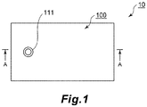
- Fig. 1 is a plan view of a hollow fiber membrane module according to an embodiment of the present disclosure.
- Fig. 2 is a front view of the hollow fiber membrane module according to the embodiment of the present disclosure and corresponds to a view when the hollow fiber membrane module is seen from the left side in Fig. 1 .
- Fig. 3 is a schematic cross-sectional view of the hollow fiber membrane module according to the embodiment of the present disclosure and is a cross-sectional view along arrows A-A in Fig. 1 .
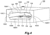
- Fig. 4 is a perspective view of a case disposed in the hollow fiber membrane module according to the embodiment of the present disclosure.
- Fig. 5 is a schematic cross-sectional view when the hollow fiber membrane module according to the embodiment of the present disclosure is used as a humidification apparatus.
- a hollow fiber membrane module 10 includes a tubular case 100, a hollow fiber membrane bundle 200 made up of a plurality of hollow fiber membranes accommodated in the case 100, and a pair of sealing and fixing portions 310 and 320 that fixes the hollow fiber membrane bundle 200 on one end and the other end of the case 100, respectively.
- an outside-membrane channel see solid-line arrows S1 and S2 in Fig. 5
- an inside-membrane channel see dot-line arrows T0 and T1 in Fig. 5
- a supply port 111 serving as an outside-membrane channel inlet for supplying moist air to the outside-membrane channel and an exhaust port 112 serving as an outside-membrane channel outlet for exhausting moist air (dried moist air) are disposed in the case 100.
- the hollow fiber membrane module 10 is used such that dry air is supplied from an opening on the other end side (the side where the sealing and fixing portion 320 is disposed) of the case 100 and dry air (humidified dry air) is exhausted from an opening on one end side (the side where the sealing and fixing portion 310 is disposed) of the case 100.
- the hollow fiber membrane module 10 will be described in more detail.
- the hollow fiber membrane module 10 includes the case 100, the hollow fiber membrane bundle 200, and the pair of sealing and fixing portions 310 and 320.
- the hollow fiber membrane bundle 200 has a configuration in which a plurality of (several hundreds to several ten thousands) hollow fiber membranes are bundled.
- a hydrophilic material is used as a material of the hollow fiber membrane.
- Nafion having a property of transmitting moisture by dissolution and diffusion, PPSU (polyphenylsulfone) having a property of transmitting moisture by a capillary condensation mechanism based on pore size control, and the like can be ideally used.
- the pair of sealing and fixing portions 310 and 320 seal the openings at both ends of the case 100 and fix the hollow fiber membrane bundle 200 to the case 100 on one end side and the other end side of the case 100 in a state in which the hollow inside of each of the hollow fiber membranes is open.
- These sealing and fixing portions 310 and 320 are formed by curing of a potting material such as an epoxy resin.
- the case 100 includes a pair of opposing planar portions 100A and 100B and a pair of side wall portions 100C and 100D connecting both sides of the pair of planar portions 100A and 100B.
- the supply port 111 serving as an outside-membrane channel inlet is disposed in one planar portion 100A
- the exhaust port 112 serving as an outside-membrane channel outlet is disposed in the other planar portion 100B.
- the supply port 111 is disposed at a position closer to one end side of the case 100
- the exhaust port 112 is disposed at a position closer to the other end side of the case 100 and on the opposite side from the supply port 111 with the hollow fiber membrane bundle 200 disposed therebetween.
- a rectification projection 120 protruding toward the outer circumferential surface of the hollow fiber membrane bundle 200 is disposed on the inner wall of each of the pair of planar portions 100A and 100B so that spaces R1 and R2 are secured.
- two rectification projections 120 are disposed in each of the planar portions 100A and 100B.
- the plurality of rectification projections 120 extend from one end of the case 100 toward the other end to perform a role of rectifying the flow of fluid.
- the hollow fiber membrane bundle 200 is in contact with the inner walls 100C1 and 100D1 of the pair of side wall portions 100C and 100D, and is not in contact with the inner walls 100A1 and 100B1 of the pair of planar portions 100A and 100B since the rectification projections 120 are disposed.
- the spaces R1 and R2 are disposed. That is, the space R1 is formed between the hollow fiber membrane bundle 200 and a portion (the inner wall 100A1 of the planar portion 100A) of the case inner wall including the opening of the supply port 111, and the space R2 is formed between the hollow fiber membrane bundle 200 and a portion (the inner wall 100B1 of the planar portion 100B) of the case inner wall including the opening of the exhaust port 112.
- a plurality of spaces R1 and R2 serving as a channel through which moist air flows from one end of the case 100 toward the other end are disposed between the hollow fiber membrane bundle 200 and the case inner wall.
- a beam-shaped portion 130 as a restriction portion restricting the hollow fiber membrane from entering into the spaces R1 and R2 is disposed partially between the hollow fiber membrane bundle 200 and the spaces R1 and R2. More specifically, the beam-shaped portion 130 is disposed to connect the rectification projection 120 and the side wall portions 100C and 100D and to connect the adjacent rectification projections 120.
- the case 100 according to the present embodiment is a resin molded product. That is, the case 100 in which the pair of planar portions 100A and 100B, the pair of side wall portions 100C and 100D, the plurality of rectification projections 120, and the plurality of beam-shaped portions 130 are disposed integrally can be obtained by resin-molding using a mold.
- a humidifying (dehumidifying) mechanism of the hollow fiber membrane module 10 according to the present embodiment will be described.
- an outside-membrane channel passing by the outer wall of each of the hollow fiber membranes of the hollow fiber membrane bundle 200 and an inside-membrane channel passing through the hollow inside of each of the hollow fiber membranes are formed.
- the outside-membrane channel is a channel through which fluid is exhausted from the supply port 111 to the exhaust port 112 along the outer wall of each of the hollow fiber membranes of the hollow fiber membrane bundle 200 (see the solid-line arrows S1 and S2 in Fig. 5 ).
- the inside-membrane channel is a channel through which fluid is exhausted from the other end of the case 100 to one end of the case 100 along the hollow inside of each of the hollow fiber membranes of the hollow fiber membrane bundle 200 (see the dot-line arrows T0 and T1 in Fig. 5 ).
- the hollow fiber membrane module 10 is used such that moist air flows through the outside-membrane channel and dry air flows through the inside-membrane channel. In this way, moisture in the moist air is supplied to the dry air and the dry air is humidified by the membrane separation effect of the hollow fiber membrane. Since the moist air is deprived of moisture, the moist air is dried. Therefore, the hollow fiber membrane module 10 can be used as a humidification apparatus or a dehumidification apparatus. Since a gap is secured between the planar portion 100A and the beam-shaped portion 130 and between the planar portion 100B and the beam-shaped portion 130, when moist air flows through the spaces R1 and R2, the beam-shaped portions 130 do not become a hindrance.
- a plurality of spaces R1 and R2 serving as a channel through which moist air flows from one end of the case 100 to the other end are disposed between the hollow fiber membrane bundle 200 and the inner wall of the case 100. Therefore, it is possible to suppress the flow of moist air from concentrating in certain locations, and to allow moist air to easily flow through the hollow fiber membrane bundle 200 over an entire area from one end side of the case 100 to the other end side and to increase the percentage of the membrane area contributing to the membrane separation effect.
- the hollow fiber membrane is restricted from entering into the spaces R1 and R2 and deformation of the hollow fiber membrane can be suppressed. In this way, it is possible to stabilize the attitudes of the hollow fiber membranes. Therefore, it is possible to suppress a large gap from being formed between the hollow fiber membranes. Therefore, it is possible to suppress moist air from leaking through a gap formed between the hollow fiber membranes from the space R1 to the space R2. In this respect, it is possible to increase the percentage of the membrane area contributing to the membrane separation effect.
- the space R1 is disposed between the hollow fiber membrane bundle 200 and the portion (the inner wall 100A1 of the planar portion 100A) of the case inner wall including an opening of the supply port 111, and the space R2 is disposed between the hollow fiber membrane bundle 200 and the portion (the inner wall 100B1 of the planar portion 100B) of the case inner wall including an opening of the exhaust port 112. In this way, it is possible to suppress the flow of moist air from concentrating near the supply port 111 ad the exhaust port 112.
- a space is not formed between the hollow fiber membrane bundle 200 and the pair of side wall portions 100C and 100D. Due to this, when moist air flows from the space R1 close to the supply port 111 to the space R2 close to the exhaust port 112, moist air does not leak between the hollow fiber membrane bundle 200 and the pair of side wall portions 100C and 100D, and the moist air flows over the entire hollow fiber membrane bundle 200. Therefore, it is possible to increase the percentage of the membrane area contributing to the membrane separation effect.
- the moist air flowing through the outside-membrane channel and the dry air flowing through the inside-membrane channel flow in opposite directions.
- the moist air flowing through the outside-membrane channel and the dry air flowing through the inside-membrane channel may flow in the same direction.
- the dry air may flow in a direction opposite to the dot-line arrow.
- the moist air and the dry air may flow in opposite directions.
- the beam-shaped portion 130 may be disposed at a plurality of locations between one end and the other end of the case 100.
Landscapes
- Chemical & Material Sciences (AREA)
- Engineering & Computer Science (AREA)
- Chemical Kinetics & Catalysis (AREA)
- General Chemical & Material Sciences (AREA)
- Manufacturing & Machinery (AREA)
- Analytical Chemistry (AREA)
- Oil, Petroleum & Natural Gas (AREA)
- Sustainable Energy (AREA)
- Life Sciences & Earth Sciences (AREA)
- Sustainable Development (AREA)
- Electrochemistry (AREA)
- General Engineering & Computer Science (AREA)
- Mechanical Engineering (AREA)
- Combustion & Propulsion (AREA)
- Separation Using Semi-Permeable Membranes (AREA)
- Fuel Cell (AREA)
- Drying Of Gases (AREA)
Abstract
Description
- The present disclosure relates to a hollow fiber membrane module usable in humidification apparatuses and dehumidification apparatuses.
- For example, in solid polymer fuel cells, a humidification apparatus that uses a hollow fiber membrane module is provided to humidify an electrolyte membrane. With reference to
Fig. 6 , a hollow fiber membrane module according to a conventional example will be described.Fig. 6 is a front view of a hollow fiber membrane module according to the conventional example. - A hollow
fiber membrane module 500 according to the conventional example includes atubular case 510 and hollowfiber membrane bundles 520 accommodated in thecase 510. In the hollowfiber membrane module 500, an outside-membrane channel passing by an outer wall of each of the hollow fiber membranes and an inside-membrane channel passing through the hollow inside of each of the hollow fiber membranes are formed. The hollowfiber membrane module 500 can be used as a humidification apparatus when a hydrophilic material is used as a material of the hollow fiber membrane. That is, when moist air flows along the outside-membrane channel and dry air flows along the inside-membrane channel, due to a membrane separation effect of the hollow fiber membrane, the moisture in the moist air is supplied to the dry air and the dry air can be humidified. Since the moist air is deprived of moisture, the hollow fiber membrane module can be also used as a dehumidification apparatus for drying the moist air. - In order to enhance humidification efficiency of the hollow
fiber membrane module 500 described above, how high the percentage of a membrane area contributing to a membrane separation effect with respect to an entire membrane area of the hollow fiber membranes accommodated in thecase 510 is important. In thecase 510, a moistair supply port 511 and a moistair exhaust port 512 are disposed in an upper part and a lower part of thecase 510 inFig. 6 , respectively. When an outer circumferential surface of the hollowfiber membrane bundle 520 is in close contact with an entire inner wall of thecase 510, the flow of fluid is apt to concentrate near thesupply port 511 and near theexhaust port 512. Therefore, in the hollowfiber membrane module 500 according to the illustrated conventional example, a plurality ofrectification projections 513 for rectifying the flow of fluid is disposed on the inner wall of thecase 510. Therectification projection 513 is disposed to protrude toward the outer circumferential surface of the hollowfiber membrane bundle 520 and extend from one end of thecase 510 toward the other end (in the drawing, the deeper side from the front side of the drawing surface) so that a space (gap) R is secured between the hollowfiber membrane bundle 520 and the inner wall of thecase 510. By disposing such arectification projection 513, it is possible to prevent the flow of fluid from concentrating near thesupply port 511 and near theexhaust port 512 and to increase the percentage of the membrane area contributing to the membrane separation effect. - However, as in the hollow
fiber membrane module 500, when the space R is disposed, a large gap may be formed between the hollow fiber membranes due to a portion of the hollow fiber membrane being deformed in order to enter into the space R. In this way, moist air may leak through the large gap to flow from thesupply port 511 to theexhaust port 512 and the membrane area that does not contribute to the membrane separation effect may increase. Therefore, conventionally, the hollowfiber membrane bundle 520 is accommodated in thecase 510 in a state in which the hollowfiber membrane bundle 520 is inserted in atube 530 manufactured using a resin mesh. Thetube 530 is manufactured by forming meshes in a tubular form and heat-welding the ends thereof. Therefore, the manufacturing cost of thetube 530 is high and an operation cost for inserting the hollowfiber membrane bundle 520 in thetube 530 is incurred. - [PTL 1] Japanese Patent Application Publication No.
2007-283292 - An object of the present disclosure is to provide a hollow fiber membrane module capable of stabilizing the attitudes of hollow fiber membranes even when a hollow fiber membrane bundle is not inserted in a tube.
- The present disclosure employs the following means in order to solve the problem.
- That is, a hollow fiber membrane module of the present disclosure includes:
- a tubular case;
- a hollow fiber membrane bundle made up of a plurality of hollow fiber membranes that is accommodated in the case; and
- a pair of sealing and fixing portions that seals an opening at each of both ends of the case and fixes the hollow fiber membrane bundle to the case on one end and the other end of the case in a state in which a hollow inside of each of the hollow fiber membranes is open, wherein
- an outside-membrane channel that passes by an outer wall of each of the hollow fiber membranes and an inside-membrane channel that passes through the hollow inside of each of the hollow fiber membranes are formed, moist air flows through the outside-membrane channel, and dry air flows through the inside-membrane channel, whereby moisture in the moist air is supplied to the dry air due to a membrane separation effect of the hollow fiber membranes,
- a plurality of spaces serving as a channel through which moist air flows from one end of the case to the other end are disposed between the case inner wall and the hollow fiber membrane bundle, and
- a restriction portion that restricts the hollow fiber membrane from entering into the space is partially disposed between the hollow fiber membrane bundle and each of the spaces.
- According to the present disclosure, a plurality of spaces serving as a channel through which moist air flows from one end of the case to the other end are disposed between the case inner wall and the hollow fiber membrane bundle. Therefore, it is possible to suppress the flow of moist air from concentrating in certain locations. Moreover, since the restriction portion is disposed, it is possible to restrict the hollow fiber membrane from entering into the space and to suppress deformation of the hollow fiber membrane. In this way, it is possible to stabilize the attitudes of the hollow fiber membranes. Therefore, it is possible to suppress a large gap from being formed between the hollow fiber membranes.
- An outside-membrane channel inlet disposed at a position closer to one end of the case and an outside-membrane channel outlet disposed at a position closer to the other end of the case on a side opposite to the outside-membrane channel inlet with the hollow fiber membrane bundle disposed therebetween may be disposed in the case,
and the space may be disposed between the hollow fiber membrane bundle and a portion of the case inner wall including an opening of the outside-membrane channel inlet, and the space may be formed between the hollow fiber membrane bundle and a portion of the case inner wall including an opening of the outside-membrane channel outlet. - In this way, it is possible to suppress the flow of moist air from concentrating near the outside-membrane channel inlet and the outside-membrane channel outlet.
- The case may include a pair of opposing planar portions and a pair of side wall portions connecting both sides of the pair of planar portions,
the outside-membrane channel inlet may be disposed in one of the pair of planar portions and the outside-membrane channel outlet may be disposed in the other planar portion, and
the hollow fiber membrane bundle may be in contact with an inner wall of the pair of side wall portions and may not be in contact with an inner wall of the pair of planar portions whereby the space is disposed. - In this way, a space is disposed between the hollow fiber membrane bundle and the planar portion where the outside-membrane channel inlet is disposed, a space is disposed between the hollow fiber membrane bundle and the planar portion where the outside-membrane channel outlet is disposed, and a space (gap) is not formed between the hollow fiber membrane bundle and the pair of side wall portions. Therefore, when moist air flows from the space close to the outside-membrane channel inlet to the space close to the outside-membrane channel outlet, the moist air does not leak from between the hollow fiber membrane bundle and the pair of side wall portions and the moist air flows through the entire hollow fiber membrane bundle.
- A plurality of rectification projections that protrudes toward an outer circumferential surface of the hollow fiber membrane bundle so that the space is secured, and extends from one end of the case to the other end to rectify the flow of fluid may be disposed on the inner wall of the pair of planar portions.
- The restriction portion may be a beam-shaped portion connecting the rectification projection and the side wall portion and connecting the adjacent rectification projections.
- The respective configurations can be employed in combinations as much as possible.
- As described above, according to the present disclosure, it is possible to stabilize the attitudes of hollow fiber membranes even when a hollow fiber membrane bundle is not inserted in a tube.
-
- [
Fig. 1 ]
Fig. 1 is a plan view of a hollow fiber membrane module according to an embodiment of the present disclosure. - [
Fig. 2 ]
Fig. 2 is a front view of the hollow fiber membrane module according to the embodiment of the present disclosure. - [
Fig. 3 ]
Fig. 3 is a schematic cross-sectional view of the hollow fiber membrane module according to the embodiment of the present disclosure. - [
Fig. 4 ]
Fig. 4 is a perspective view of a case according to the embodiment of the present disclosure. - [
Fig. 5 ]
Fig. 5 is a schematic cross-sectional view illustrating a major configuration of a humidification apparatus that uses the hollow fiber membrane module according to the embodiment of the present disclosure. - [
Fig. 6 ]
Fig. 6 is a front view of a hollow fiber membrane module according to a conventional example. - Hereinafter, mode for carrying out the present disclosure will be described in detail on the basis of exemplary embodiments with reference to the drawings. However, dimensions, materials, shapes, relative arrangements, and the like of components disclosed in the embodiment are not intended to limit the scope of the present disclosure unless particularly stated otherwise. A hollow fiber membrane module according to the present embodiment can be ideally used as a humidification apparatus for humidifying an electrolyte membrane in a solid polymer fuel cell, for example. However, the hollow fiber membrane module can be also used as a dehumidification apparatus.
- With reference to
Figs. 1 to 5 , a hollow fiber membrane module according to an embodiment of the present disclosure will be described.Fig. 1 is a plan view of a hollow fiber membrane module according to an embodiment of the present disclosure.Fig. 2 is a front view of the hollow fiber membrane module according to the embodiment of the present disclosure and corresponds to a view when the hollow fiber membrane module is seen from the left side inFig. 1 .Fig. 3 is a schematic cross-sectional view of the hollow fiber membrane module according to the embodiment of the present disclosure and is a cross-sectional view along arrows A-A inFig. 1 .Fig. 4 is a perspective view of a case disposed in the hollow fiber membrane module according to the embodiment of the present disclosure.Fig. 5 is a schematic cross-sectional view when the hollow fiber membrane module according to the embodiment of the present disclosure is used as a humidification apparatus. - A case in which a hollow fiber membrane module according to the present embodiment is used as a humidification apparatus will be described particularly with reference to
Fig. 5 . A hollowfiber membrane module 10 includes atubular case 100, a hollowfiber membrane bundle 200 made up of a plurality of hollow fiber membranes accommodated in thecase 100, and a pair of sealing and fixingportions fiber membrane bundle 200 on one end and the other end of thecase 100, respectively. In the hollowfiber membrane module 10 configured in this manner, an outside-membrane channel (see solid-line arrows S1 and S2 inFig. 5 ) passing through an outer wall of each of the hollow fiber membranes and an inside-membrane channel (see dot-line arrows T0 and T1 inFig. 5 ) passing through the follow inside of each of the hollow fiber membranes are formed. - A
supply port 111 serving as an outside-membrane channel inlet for supplying moist air to the outside-membrane channel and anexhaust port 112 serving as an outside-membrane channel outlet for exhausting moist air (dried moist air) are disposed in thecase 100. Moreover, the hollowfiber membrane module 10 is used such that dry air is supplied from an opening on the other end side (the side where the sealing and fixingportion 320 is disposed) of thecase 100 and dry air (humidified dry air) is exhausted from an opening on one end side (the side where the sealing and fixingportion 310 is disposed) of thecase 100. - The hollow
fiber membrane module 10 will be described in more detail. As described above, the hollowfiber membrane module 10 includes thecase 100, the hollowfiber membrane bundle 200, and the pair of sealing and fixingportions fiber membrane bundle 200 has a configuration in which a plurality of (several hundreds to several ten thousands) hollow fiber membranes are bundled. A hydrophilic material is used as a material of the hollow fiber membrane. For example, Nafion having a property of transmitting moisture by dissolution and diffusion, PPSU (polyphenylsulfone) having a property of transmitting moisture by a capillary condensation mechanism based on pore size control, and the like can be ideally used. Since these materials have low elution properties and high strength, these materials can be ideally used in a humidification apparatus and a dehumidification apparatus. The pair of sealing and fixingportions case 100 and fix the hollowfiber membrane bundle 200 to thecase 100 on one end side and the other end side of thecase 100 in a state in which the hollow inside of each of the hollow fiber membranes is open. These sealing and fixingportions - The
case 100 will be described in more detail. Thecase 100 includes a pair of opposingplanar portions side wall portions planar portions supply port 111 serving as an outside-membrane channel inlet is disposed in oneplanar portion 100A, and theexhaust port 112 serving as an outside-membrane channel outlet is disposed in the otherplanar portion 100B. Thesupply port 111 is disposed at a position closer to one end side of thecase 100, and theexhaust port 112 is disposed at a position closer to the other end side of thecase 100 and on the opposite side from thesupply port 111 with the hollowfiber membrane bundle 200 disposed therebetween. Moreover, arectification projection 120 protruding toward the outer circumferential surface of the hollowfiber membrane bundle 200 is disposed on the inner wall of each of the pair ofplanar portions rectification projections 120 are disposed in each of theplanar portions rectification projections 120 extend from one end of thecase 100 toward the other end to perform a role of rectifying the flow of fluid. - The hollow
fiber membrane bundle 200 is in contact with the inner walls 100C1 and 100D1 of the pair ofside wall portions planar portions rectification projections 120 are disposed. In this way, the spaces R1 and R2 are disposed. That is, the space R1 is formed between the hollowfiber membrane bundle 200 and a portion (the inner wall 100A1 of theplanar portion 100A) of the case inner wall including the opening of thesupply port 111, and the space R2 is formed between the hollowfiber membrane bundle 200 and a portion (the inner wall 100B1 of theplanar portion 100B) of the case inner wall including the opening of theexhaust port 112. In this way, a plurality of spaces R1 and R2 serving as a channel through which moist air flows from one end of thecase 100 toward the other end are disposed between the hollowfiber membrane bundle 200 and the case inner wall. - A beam-shaped
portion 130 as a restriction portion restricting the hollow fiber membrane from entering into the spaces R1 and R2 is disposed partially between the hollowfiber membrane bundle 200 and the spaces R1 and R2. More specifically, the beam-shapedportion 130 is disposed to connect therectification projection 120 and theside wall portions adjacent rectification projections 120. Thecase 100 according to the present embodiment is a resin molded product. That is, thecase 100 in which the pair ofplanar portions side wall portions rectification projections 120, and the plurality of beam-shapedportions 130 are disposed integrally can be obtained by resin-molding using a mold. - A humidifying (dehumidifying) mechanism of the hollow
fiber membrane module 10 according to the present embodiment will be described. As described above, in the hollowfiber membrane module 10 according to the present embodiment, an outside-membrane channel passing by the outer wall of each of the hollow fiber membranes of the hollowfiber membrane bundle 200 and an inside-membrane channel passing through the hollow inside of each of the hollow fiber membranes are formed. The outside-membrane channel is a channel through which fluid is exhausted from thesupply port 111 to theexhaust port 112 along the outer wall of each of the hollow fiber membranes of the hollow fiber membrane bundle 200 (see the solid-line arrows S1 and S2 inFig. 5 ). The inside-membrane channel is a channel through which fluid is exhausted from the other end of thecase 100 to one end of thecase 100 along the hollow inside of each of the hollow fiber membranes of the hollow fiber membrane bundle 200 (see the dot-line arrows T0 and T1 inFig. 5 ). - In the present embodiment, the hollow
fiber membrane module 10 is used such that moist air flows through the outside-membrane channel and dry air flows through the inside-membrane channel. In this way, moisture in the moist air is supplied to the dry air and the dry air is humidified by the membrane separation effect of the hollow fiber membrane. Since the moist air is deprived of moisture, the moist air is dried. Therefore, the hollowfiber membrane module 10 can be used as a humidification apparatus or a dehumidification apparatus. Since a gap is secured between theplanar portion 100A and the beam-shapedportion 130 and between theplanar portion 100B and the beam-shapedportion 130, when moist air flows through the spaces R1 and R2, the beam-shapedportions 130 do not become a hindrance. - According to the hollow
fiber membrane module 10 according to the present embodiment, a plurality of spaces R1 and R2 serving as a channel through which moist air flows from one end of thecase 100 to the other end are disposed between the hollowfiber membrane bundle 200 and the inner wall of thecase 100. Therefore, it is possible to suppress the flow of moist air from concentrating in certain locations, and to allow moist air to easily flow through the hollowfiber membrane bundle 200 over an entire area from one end side of thecase 100 to the other end side and to increase the percentage of the membrane area contributing to the membrane separation effect. In the hollowfiber membrane module 10 according to the present embodiment, since the beam-shapedportion 130 as a restriction portion is disposed in thecase 100, the hollow fiber membrane is restricted from entering into the spaces R1 and R2 and deformation of the hollow fiber membrane can be suppressed. In this way, it is possible to stabilize the attitudes of the hollow fiber membranes. Therefore, it is possible to suppress a large gap from being formed between the hollow fiber membranes. Therefore, it is possible to suppress moist air from leaking through a gap formed between the hollow fiber membranes from the space R1 to the space R2. In this respect, it is possible to increase the percentage of the membrane area contributing to the membrane separation effect. - The space R1 is disposed between the hollow
fiber membrane bundle 200 and the portion (the inner wall 100A1 of theplanar portion 100A) of the case inner wall including an opening of thesupply port 111, and the space R2 is disposed between the hollowfiber membrane bundle 200 and the portion (the inner wall 100B1 of theplanar portion 100B) of the case inner wall including an opening of theexhaust port 112. In this way, it is possible to suppress the flow of moist air from concentrating near thesupply port 111 ad theexhaust port 112. - Furthermore, in the hollow
fiber membrane module 10 according to the present embodiment, a space (gap) is not formed between the hollowfiber membrane bundle 200 and the pair ofside wall portions supply port 111 to the space R2 close to theexhaust port 112, moist air does not leak between the hollowfiber membrane bundle 200 and the pair ofside wall portions fiber membrane bundle 200. Therefore, it is possible to increase the percentage of the membrane area contributing to the membrane separation effect. - In the above-described embodiment, a case in which the moist air flowing through the outside-membrane channel and the dry air flowing through the inside-membrane channel flow in opposite directions has been described. However, the moist air flowing through the outside-membrane channel and the dry air flowing through the inside-membrane channel may flow in the same direction. For example, in the inside-membrane channel, the dry air may flow in a direction opposite to the dot-line arrow. However, in order to enhance the humidification efficiency and the dehumidification efficiency, the moist air and the dry air may flow in opposite directions. Moreover, in the above-described embodiment, a case in which the beam-shaped
portion 130 is disposed only in one location near the center between one end and the other end of thecase 100. However, the beam-shapedportion 130 may be disposed at a plurality of locations between one end and the other end of thecase 100. -
- 10
- Hollow fiber membrane module
- 50
- First head
- 51
- Supply port
- 52
- Exhaust port
- 60
- Second head
- 61
- Exhaust port
- 62
- Supply port
- 100
- Case
- 100A, 100B
- Planar portion
- 100A1, 100B1
- Inner wall
- 100C, 100D
- Side wall portion
- 100C1, 100D1
- Inner wall
- 111
- Supply port
- 112
- Exhaust port
- 120
- Rectification projection
- 130
- Beam-shaped portion
- 200
- Hollow fiber membrane bundle
- 310, 320
- Sealing and fixing portion
- R1, R2
- Space
Claims (5)
- A hollow fiber membrane module comprising:a tubular case;a hollow fiber membrane bundle made up of a plurality of hollow fiber membranes that is accommodated in the case; anda pair of sealing and fixing portions that seals an opening at each of both ends of the case and fixes the hollow fiber membrane bundle to the case on one end and the other end of the case in a state in which a hollow inside of each of the hollow fiber membranes is open, whereinan outside-membrane channel that passes by an outer wall of each of the hollow fiber membranes and an inside-membrane channel that passes through the hollow inside of each of the hollow fiber membranes are formed, moist air flows through the outside-membrane channel, and dry air flows through the inside-membrane channel, whereby moisture in the moist air is supplied to the dry air due to a membrane separation effect of the hollow fiber membranes,a plurality of spaces serving as a channel through which moist air flows from one end of the case to the other end are disposed between the case inner wall and the hollow fiber membrane bundle, anda restriction portion that restricts the hollow fiber membrane from entering into the space is partially disposed between the hollow fiber membrane bundle and each of the spaces.
- The hollow fiber membrane module according to claim 1, wherein
an outside-membrane channel inlet disposed at a position closer to one end of the case and an outside-membrane channel outlet disposed at a position closer to the other end of the case on a side opposite to the outside-membrane channel inlet with the hollow fiber membrane bundle disposed therebetween are disposed in the case, and
the space is disposed between the hollow fiber membrane bundle and a portion of the case inner wall including an opening of the outside-membrane channel inlet, and the space is formed between the hollow fiber membrane bundle and a portion of the case inner wall including an opening of the outside-membrane channel outlet. - The hollow fiber membrane module according to claim 2, wherein
the case includes a pair of opposing planar portions and a pair of side wall portions each connecting both sides of the pair of planar portions,
the outside-membrane channel inlet is disposed in one of the pair of planar portions and the outside-membrane channel outlet is disposed in the other planar portion, and
the hollow fiber membrane bundle is in contact with an inner wall of the pair of side wall portions and is not in contact with an inner wall of the pair of planar portions whereby the space is disposed. - The hollow fiber membrane module according to claim 1, 2, or 3, wherein
a plurality of rectification projections that protrudes toward an outer circumferential surface of the hollow fiber membrane bundle such that the space is secured, and extends from one end of the case to the other end to rectify the flow of fluid are disposed on the inner wall of the pair of planar portions. - The hollow fiber membrane module according to claim 4, wherein the restriction portion is a beam-shaped portion connecting the rectification projection and the side wall portion and connecting the adjacent rectification projections.
Applications Claiming Priority (2)
| Application Number | Priority Date | Filing Date | Title |
|---|---|---|---|
| JP2018142504 | 2018-07-30 | ||
| PCT/JP2019/028703 WO2020026875A1 (en) | 2018-07-30 | 2019-07-22 | Hollow fiber membrane module |
Publications (2)
| Publication Number | Publication Date |
|---|---|
| EP3831464A1 true EP3831464A1 (en) | 2021-06-09 |
| EP3831464A4 EP3831464A4 (en) | 2022-06-29 |
Family
ID=69231764
Family Applications (1)
| Application Number | Title | Priority Date | Filing Date |
|---|---|---|---|
| EP19843737.8A Pending EP3831464A4 (en) | 2018-07-30 | 2019-07-22 | Hollow fiber membrane module |
Country Status (5)
| Country | Link |
|---|---|
| US (1) | US11351504B2 (en) |
| EP (1) | EP3831464A4 (en) |
| JP (1) | JP7026797B2 (en) |
| CN (1) | CN111683730B (en) |
| WO (1) | WO2020026875A1 (en) |
Families Citing this family (4)
| Publication number | Priority date | Publication date | Assignee | Title |
|---|---|---|---|---|
| EP4349466A4 (en) * | 2021-06-02 | 2025-04-30 | NOK Corporation | Hollow fiber membrane module |
| CN117480002A (en) * | 2021-10-06 | 2024-01-30 | Nok株式会社 | Hollow fiber membrane module |
| EP4670826A1 (en) * | 2023-02-21 | 2025-12-31 | NOK Corporation | HOLLOW FIBER MEMBRANE MODULE |
| KR20240150183A (en) * | 2023-04-07 | 2024-10-15 | 코오롱인더스트리 주식회사 | Mid-case of Humidifier for Fuel Cell and Humidifier for Fuel Cell |
Family Cites Families (16)
| Publication number | Priority date | Publication date | Assignee | Title |
|---|---|---|---|---|
| JPS5757555A (en) * | 1980-09-25 | 1982-04-06 | Terumo Corp | Hollow fiber type artificial lung |
| JPH0319535U (en) | 1989-07-06 | 1991-02-26 | ||
| JP2003065566A (en) * | 2001-08-24 | 2003-03-05 | Honda Motor Co Ltd | Gas humidifier and gas humidification system |
| JP4100209B2 (en) * | 2002-11-08 | 2008-06-11 | Nok株式会社 | Membrane module |
| JP4111086B2 (en) * | 2003-07-17 | 2008-07-02 | Nok株式会社 | Hollow fiber membrane module and fuel cell humidifier |
| DE102004022021B4 (en) * | 2004-05-03 | 2007-05-16 | Daimler Chrysler Ag | Moisture exchange module with a bundle of moisture permeable hollow fiber membranes |
| JP2006314919A (en) | 2005-05-12 | 2006-11-24 | Nok Corp | Hollow fiber membrane module |
| JP5012109B2 (en) | 2006-03-24 | 2012-08-29 | Nok株式会社 | Hollow fiber membrane module |
| JP5074743B2 (en) * | 2006-11-13 | 2012-11-14 | トヨタ自動車株式会社 | Hollow fiber membrane module, fuel cell system |
| US7871520B2 (en) * | 2007-12-18 | 2011-01-18 | Milton Roy Company | High-temperature membrane distillation |
| US20090242474A1 (en) * | 2008-04-01 | 2009-10-01 | Nok Corporation | Hollow fiber membrane module |
| JP5481204B2 (en) | 2010-01-07 | 2014-04-23 | 本田技研工業株式会社 | Humidification module |
| EP2420262B1 (en) * | 2010-08-19 | 2013-04-17 | Sorin Group Italia S.r.l. | Blood processing unit with modified flow path |
| JP2012130864A (en) | 2010-12-22 | 2012-07-12 | Toray Ind Inc | Hollow fiber membrane module |
| KR101673667B1 (en) * | 2014-07-31 | 2016-11-07 | 현대자동차주식회사 | Device for adjusting hollow fiber density for humidification device of fuel cell |
| CN110545902B (en) * | 2017-04-11 | 2021-12-21 | Nok株式会社 | Hollow fiber membrane module |
-
2019
- 2019-07-22 EP EP19843737.8A patent/EP3831464A4/en active Pending
- 2019-07-22 US US16/963,558 patent/US11351504B2/en active Active
- 2019-07-22 JP JP2020533442A patent/JP7026797B2/en active Active
- 2019-07-22 CN CN201980009173.0A patent/CN111683730B/en active Active
- 2019-07-22 WO PCT/JP2019/028703 patent/WO2020026875A1/en not_active Ceased
Also Published As
| Publication number | Publication date |
|---|---|
| JPWO2020026875A1 (en) | 2021-01-07 |
| US11351504B2 (en) | 2022-06-07 |
| EP3831464A4 (en) | 2022-06-29 |
| WO2020026875A1 (en) | 2020-02-06 |
| CN111683730B (en) | 2022-06-14 |
| US20200353416A1 (en) | 2020-11-12 |
| CN111683730A (en) | 2020-09-18 |
| JP7026797B2 (en) | 2022-02-28 |
Similar Documents
| Publication | Publication Date | Title |
|---|---|---|
| US11351504B2 (en) | Hollow fiber membrane module | |
| US7624971B2 (en) | Humidifying system | |
| CN110545902B (en) | Hollow fiber membrane module | |
| US12611631B2 (en) | Hollow fiber membrane module | |
| US10170779B2 (en) | Humidifier for fuel cell | |
| KR102447975B1 (en) | Membrane humidifier for fuel cell | |
| EP4349467A1 (en) | Hollow fiber membrane module and dehumidification and humidification device | |
| CN117836050A (en) | Humidifier with channel plate, channel section plate for humidifier and channel plate | |
| KR20230107227A (en) | fuel cell humidifier | |
| US20240173675A1 (en) | Hollow fiber membrane module and dehumidification/humidification device | |
| US12605675B2 (en) | Hollow fiber membrane module | |
| JP7653515B2 (en) | Hollow fiber membrane module | |
| EP4725590A1 (en) | Hollow fiber membrane module | |
| CA3214464C (en) | Hollow fiber membrane module | |
| JP2018199098A (en) | Membrane separator | |
| US20240375052A1 (en) | Hollow fiber membrane module | |
| CN117460569A (en) | Hollow fiber membrane module | |
| KR20260005749A (en) | Fuel cell membrane humidifier for increasing fluid residence time | |
| EP4670827A1 (en) | HOLLOW FIBER MEMBRANE MODULE | |
| CA3288693A1 (en) | Hollow fiber membrane module | |
| EP4670826A1 (en) | HOLLOW FIBER MEMBRANE MODULE | |
| WO2024176970A1 (en) | Hollow fiber membrane module | |
| JP2018176095A (en) | Hollow fiber membrane module |
Legal Events
| Date | Code | Title | Description |
|---|---|---|---|
| STAA | Information on the status of an ep patent application or granted ep patent |
Free format text: STATUS: THE INTERNATIONAL PUBLICATION HAS BEEN MADE |
|
| PUAI | Public reference made under article 153(3) epc to a published international application that has entered the european phase |
Free format text: ORIGINAL CODE: 0009012 |
|
| STAA | Information on the status of an ep patent application or granted ep patent |
Free format text: STATUS: REQUEST FOR EXAMINATION WAS MADE |
|
| 17P | Request for examination filed |
Effective date: 20200722 |
|
| AK | Designated contracting states |
Kind code of ref document: A1 Designated state(s): AL AT BE BG CH CY CZ DE DK EE ES FI FR GB GR HR HU IE IS IT LI LT LU LV MC MK MT NL NO PL PT RO RS SE SI SK SM TR |
|
| DAV | Request for validation of the european patent (deleted) | ||
| DAX | Request for extension of the european patent (deleted) | ||
| A4 | Supplementary search report drawn up and despatched |
Effective date: 20220531 |
|
| RIC1 | Information provided on ipc code assigned before grant |
Ipc: H01M 8/10 20160101ALI20220524BHEP Ipc: H01M 8/04291 20160101ALI20220524BHEP Ipc: H01M 8/04119 20160101ALI20220524BHEP Ipc: H01M 8/04 20160101ALI20220524BHEP Ipc: F24F 6/04 20060101ALI20220524BHEP Ipc: B01D 63/02 20060101ALI20220524BHEP Ipc: B01D 53/26 20060101ALI20220524BHEP Ipc: B01D 53/22 20060101AFI20220524BHEP |
|
| RIC1 | Information provided on ipc code assigned before grant |
Ipc: H01M 8/10 20160101ALI20220704BHEP Ipc: H01M 8/04291 20160101ALI20220704BHEP Ipc: H01M 8/04119 20160101ALI20220704BHEP Ipc: H01M 8/04 20160101ALI20220704BHEP Ipc: F24F 6/04 20060101ALI20220704BHEP Ipc: B01D 63/02 20060101ALI20220704BHEP Ipc: B01D 53/26 20060101ALI20220704BHEP Ipc: B01D 53/22 20060101AFI20220704BHEP |
|
| STAA | Information on the status of an ep patent application or granted ep patent |
Free format text: STATUS: EXAMINATION IS IN PROGRESS |
|
| 17Q | First examination report despatched |
Effective date: 20251006 |