EP3831313A2 - Hand-held surgical instruments - Google Patents
Hand-held surgical instruments Download PDFInfo
- Publication number
- EP3831313A2 EP3831313A2 EP20211928.5A EP20211928A EP3831313A2 EP 3831313 A2 EP3831313 A2 EP 3831313A2 EP 20211928 A EP20211928 A EP 20211928A EP 3831313 A2 EP3831313 A2 EP 3831313A2
- Authority
- EP
- European Patent Office
- Prior art keywords
- rack
- pinion gear
- handle
- idler pinion
- housing
- Prior art date
- Legal status (The legal status is an assumption and is not a legal conclusion. Google has not performed a legal analysis and makes no representation as to the accuracy of the status listed.)
- Pending
Links
Images


Classifications
-
- A—HUMAN NECESSITIES
- A61—MEDICAL OR VETERINARY SCIENCE; HYGIENE
- A61B—DIAGNOSIS; SURGERY; IDENTIFICATION
- A61B17/00—Surgical instruments, devices or methods
- A61B17/068—Surgical staplers, e.g. containing multiple staples or clamps
- A61B17/072—Surgical staplers, e.g. containing multiple staples or clamps for applying a row of staples in a single action, e.g. the staples being applied simultaneously
-
- A—HUMAN NECESSITIES
- A61—MEDICAL OR VETERINARY SCIENCE; HYGIENE
- A61B—DIAGNOSIS; SURGERY; IDENTIFICATION
- A61B17/00—Surgical instruments, devices or methods
- A61B17/068—Surgical staplers, e.g. containing multiple staples or clamps
- A61B17/072—Surgical staplers, e.g. containing multiple staples or clamps for applying a row of staples in a single action, e.g. the staples being applied simultaneously
- A61B17/07207—Surgical staplers, e.g. containing multiple staples or clamps for applying a row of staples in a single action, e.g. the staples being applied simultaneously the staples being applied sequentially
-
- A—HUMAN NECESSITIES
- A61—MEDICAL OR VETERINARY SCIENCE; HYGIENE
- A61B—DIAGNOSIS; SURGERY; IDENTIFICATION
- A61B17/00—Surgical instruments, devices or methods
- A61B2017/00017—Electrical control of surgical instruments
- A61B2017/00115—Electrical control of surgical instruments with audible or visual output
-
- A—HUMAN NECESSITIES
- A61—MEDICAL OR VETERINARY SCIENCE; HYGIENE
- A61B—DIAGNOSIS; SURGERY; IDENTIFICATION
- A61B17/00—Surgical instruments, devices or methods
- A61B2017/0023—Surgical instruments, devices or methods disposable
-
- A—HUMAN NECESSITIES
- A61—MEDICAL OR VETERINARY SCIENCE; HYGIENE
- A61B—DIAGNOSIS; SURGERY; IDENTIFICATION
- A61B17/00—Surgical instruments, devices or methods
- A61B2017/00367—Details of actuation of instruments, e.g. relations between pushing buttons, or the like, and activation of the tool, working tip, or the like
- A61B2017/00398—Details of actuation of instruments, e.g. relations between pushing buttons, or the like, and activation of the tool, working tip, or the like using powered actuators, e.g. stepper motors, solenoids
-
- A—HUMAN NECESSITIES
- A61—MEDICAL OR VETERINARY SCIENCE; HYGIENE
- A61B—DIAGNOSIS; SURGERY; IDENTIFICATION
- A61B17/00—Surgical instruments, devices or methods
- A61B2017/0042—Surgical instruments, devices or methods with special provisions for gripping
- A61B2017/00424—Surgical instruments, devices or methods with special provisions for gripping ergonomic, e.g. fitting in fist
-
- A—HUMAN NECESSITIES
- A61—MEDICAL OR VETERINARY SCIENCE; HYGIENE
- A61B—DIAGNOSIS; SURGERY; IDENTIFICATION
- A61B17/00—Surgical instruments, devices or methods
- A61B2017/0046—Surgical instruments, devices or methods with a releasable handle; with handle and operating part separable
-
- A—HUMAN NECESSITIES
- A61—MEDICAL OR VETERINARY SCIENCE; HYGIENE
- A61B—DIAGNOSIS; SURGERY; IDENTIFICATION
- A61B17/00—Surgical instruments, devices or methods
- A61B2017/0046—Surgical instruments, devices or methods with a releasable handle; with handle and operating part separable
- A61B2017/00473—Distal part, e.g. tip or head
-
- A—HUMAN NECESSITIES
- A61—MEDICAL OR VETERINARY SCIENCE; HYGIENE
- A61B—DIAGNOSIS; SURGERY; IDENTIFICATION
- A61B17/00—Surgical instruments, devices or methods
- A61B2017/00477—Coupling
-
- A—HUMAN NECESSITIES
- A61—MEDICAL OR VETERINARY SCIENCE; HYGIENE
- A61B—DIAGNOSIS; SURGERY; IDENTIFICATION
- A61B17/00—Surgical instruments, devices or methods
- A61B2017/00681—Aspects not otherwise provided for
- A61B2017/00734—Aspects not otherwise provided for battery operated
-
- A—HUMAN NECESSITIES
- A61—MEDICAL OR VETERINARY SCIENCE; HYGIENE
- A61B—DIAGNOSIS; SURGERY; IDENTIFICATION
- A61B17/00—Surgical instruments, devices or methods
- A61B17/068—Surgical staplers, e.g. containing multiple staples or clamps
- A61B17/072—Surgical staplers, e.g. containing multiple staples or clamps for applying a row of staples in a single action, e.g. the staples being applied simultaneously
- A61B2017/07214—Stapler heads
- A61B2017/07221—Stapler heads curved
-
- A—HUMAN NECESSITIES
- A61—MEDICAL OR VETERINARY SCIENCE; HYGIENE
- A61B—DIAGNOSIS; SURGERY; IDENTIFICATION
- A61B17/00—Surgical instruments, devices or methods
- A61B17/068—Surgical staplers, e.g. containing multiple staples or clamps
- A61B17/072—Surgical staplers, e.g. containing multiple staples or clamps for applying a row of staples in a single action, e.g. the staples being applied simultaneously
- A61B2017/07214—Stapler heads
- A61B2017/07257—Stapler heads characterised by its anvil
-
- A—HUMAN NECESSITIES
- A61—MEDICAL OR VETERINARY SCIENCE; HYGIENE
- A61B—DIAGNOSIS; SURGERY; IDENTIFICATION
- A61B17/00—Surgical instruments, devices or methods
- A61B17/068—Surgical staplers, e.g. containing multiple staples or clamps
- A61B17/072—Surgical staplers, e.g. containing multiple staples or clamps for applying a row of staples in a single action, e.g. the staples being applied simultaneously
- A61B2017/07214—Stapler heads
- A61B2017/07271—Stapler heads characterised by its cartridge
-
- A—HUMAN NECESSITIES
- A61—MEDICAL OR VETERINARY SCIENCE; HYGIENE
- A61B—DIAGNOSIS; SURGERY; IDENTIFICATION
- A61B17/00—Surgical instruments, devices or methods
- A61B17/068—Surgical staplers, e.g. containing multiple staples or clamps
- A61B17/072—Surgical staplers, e.g. containing multiple staples or clamps for applying a row of staples in a single action, e.g. the staples being applied simultaneously
- A61B2017/07214—Stapler heads
- A61B2017/07278—Stapler heads characterised by its sled or its staple holder
-
- A—HUMAN NECESSITIES
- A61—MEDICAL OR VETERINARY SCIENCE; HYGIENE
- A61B—DIAGNOSIS; SURGERY; IDENTIFICATION
- A61B17/00—Surgical instruments, devices or methods
- A61B17/28—Surgical forceps
- A61B17/29—Forceps for use in minimally invasive surgery
- A61B17/2909—Handles
- A61B2017/2912—Handles transmission of forces to actuating rod or piston
- A61B2017/2923—Toothed members, e.g. rack and pinion
-
- A—HUMAN NECESSITIES
- A61—MEDICAL OR VETERINARY SCIENCE; HYGIENE
- A61B—DIAGNOSIS; SURGERY; IDENTIFICATION
- A61B17/00—Surgical instruments, devices or methods
- A61B17/28—Surgical forceps
- A61B17/29—Forceps for use in minimally invasive surgery
- A61B2017/2926—Details of heads or jaws
- A61B2017/2927—Details of heads or jaws the angular position of the head being adjustable with respect to the shaft
-
- A—HUMAN NECESSITIES
- A61—MEDICAL OR VETERINARY SCIENCE; HYGIENE
- A61B—DIAGNOSIS; SURGERY; IDENTIFICATION
- A61B17/00—Surgical instruments, devices or methods
- A61B17/28—Surgical forceps
- A61B17/29—Forceps for use in minimally invasive surgery
- A61B2017/2948—Sealing means, e.g. for sealing the interior from fluid entry
Definitions
- the electromechanical surgical instruments include a handle assembly, which is reusable, and disposable loading units and/or single use loading units, such as, for example, surgical end effectors that are selectively connected to the handle assembly prior to use and then disconnected from the handle assembly following use in order to be disposed of or in some instances sterilized for re-use.
- a handle assembly of a hand-held surgical instrument includes a handle housing, a rack supported in the handle housing, an inner housing located within the handle housing, and an idler pinion gear.
- the rack is axially movable within the handle housing and configured to operably couple to a driven member of a surgical end effector.
- the idler pinion gear is supported in the inner housing and operably coupled to the rack. The idler pinion gear is configured to translate the rack.
- the handle housing may include a barrel portion, and a handle portion extending transversely and proximally from the barrel portion.
- the rack may be located in the barrel portion and may define a longitudinal axis that is parallel with a longitudinal axis defined by the barrel portion.
- the idler pinion gear may include an upper end portion engaged with the rack, and a lower end portion.
- the idler pinion gear may define a recess located between the upper and lower end portions.
- the idler pinion gear may have an O-ring seal located in the recess.
- the idler pinion gear may be rotatable relative to and within the inner housing.
- the lower end portion of the idler pinion gear may protrude from the inner housing.
- the handle assembly may further include a motor configured to be located within the handle housing, and a pinion gear operably coupled to the motor and configured to engage the lower end portion of the idler pinion gear.
- the inner housing may define a first longitudinally-extending channel.
- the rack may extend through the first channel.
- the inner housing may define a second channel extending transversely relative to the first channel and in communication with the first channel.
- the idler pinion gear may be received in the second channel.
- a hand-held surgical instrument in accordance with another aspect of the disclosure, includes a handle housing, an instrument module configured for receipt in the handle housing, and a rack supported in the handle housing.
- the instrument module includes a motor and a gear operably coupled to the motor.
- the rack is supported in the handle housing and is axially movable within the handle housing.
- the rack is configured to operably couple to a driven member of a surgical end effector.
- the gear is configured to operable couple to the rack, such that a rotation of the gear results in a translation of the rack.
- the hand-held surgical instrument may further include an outer shell configured for receipt in the handle housing.
- the outer shell houses the instrument module therein.
- the hand-held surgical instrument may further include an inner housing located within the handle housing.
- the inner housing may define a first channel having the rack extending therethrough.
- the hand-held surgical instrument may further include an idler pinion gear supported in a second channel of the inner housing and operably coupled to the rack.
- the idler pinion gear may be configured to translate the rack in response to a rotation of the gear of the instrument module.
- the hand-held surgical instrument may further include an idler pinion gear having an upper end portion engaged with the rack, and a lower end portion configured to engage the gear of the instrument module.
- the idler pinion gear may define a recess located between the upper and lower end portions.
- the idler pinion gear may have an O-ring seal located in the recess.
- the instrument module may further include a battery for powering the motor.
- the hand-held surgical instrument may further include a button movably coupled to the handle housing, and a printed circuit board.
- the button may be associated with the printed circuit board, and the battery may be detachably coupled to the printed circuit board, such that an actuation of the button activates the battery.
- parallel and perpendicular are understood to include relative configurations that are substantially parallel and substantially perpendicular up to about + or - 10 degrees from true parallel and true perpendicular.
- distal refers to that portion of the surgical instrument, or component thereof, farther from the user
- proximal refers to that portion of the surgical instrument, or component thereof, closer to the user.
- a handle assembly of a hand-held surgical instrument having a motor-driven pinion gear and a rack operably coupled to the gear.
- the rack is configured to carry out a function of a surgical end effector coupled to the handle assembly in response to an actuation of the motor.
- an ergonomic, disposable handle housing and a reusable power assembly e.g., an instrument module housed within a sterile or non-sterile outer casing.
- a surgical instrument in accordance with an embodiment of the present disclosure, is generally designated as 10, and is in the form of a powered hand-held electromechanical surgical instrument configured for selective coupling thereto of a plurality of different surgical end effectors, for example, the surgical end effector 200 of FIGS. 1 and 7 .
- the end effector 200 is configured for actuation and manipulation by the powered hand-held electromechanical surgical instrument 10.
- the hand-held electromechanical surgical instrument 10 includes a handle assembly 100, a knob housing 102 coupled to the handle assembly 100, and a shaft portion 104 extending distally from the knob housing 102 and configured for selective connection with a surgical attachment, such as, for example, the end effector 200.
- the handle assembly 100 includes a disposable and sterile handle housing 110 having a body, such as, for example, a barrel portion 118, a handle portion 108 extending perpendicularly downward from the barrel portion 118 or transversely and proximally from the barrel portion 118, and a hinged door 120 pivotably coupled to the handle portion 108.
- the door 120 is selectively opened and closed to allow for the insertion or removal of a non-sterile power assembly 122.
- the handle portion 108 and the door 120 each have an inner periphery collectively defining a sterile barrier 117 ( FIG. 4 ) for the power assembly 122 upon closing the door 120.
- a proximal end portion or any suitable location of the barrel portion 118 may have a clear window (not shown) to allow for viewing of a display (e.g., an LCD, not shown).
- the handle assembly 100 has a fire switch 106 configured and adapted to actuate the various functions of the end effector 200.
- the fire switch 106 may be constructed as a toggle bar pivotably coupled to the handle portion 108 of the handle housing 110.
- An activation of the fire switch 106 activates a motor 112 ( FIGS. 3A and 3B ) to advance or retract a firing rod (not explicitly shown) of the surgical instrument 10 depending on whether a top button 106a or a bottom button 106b of the fire switch 106 is actuated.
- the firing rod is coupled to a drive assembly 209 ( FIG.
- the end effector 200 (which includes a knife rod 211 and an actuation sled 213), such that advancement of the firing rod advances the drive assembly 209 of the end effector 200, which closes the jaw members 206, 208 of the end effector 200 and fires the end effector 200 when a safety switch 116 is in an actuated state.
- the handle assembly 100 has an articulation switch 114 extending transversely through the handle portion 108 and protruding outwardly from left and right sides of the handle portion 108.
- the articulation switch 114 is configured to actuate an articulation of the end effector 200 (e.g., move the end effector 200 along a horizontal plane between a position coaxial with the shaft portion 104 and multiple positions out of alignment with the shaft portion 104).
- the knob housing 102 is rotatably coupled to the handle housing 110 and has the shaft portion 104 non-rotationally coupled thereto.
- a manual rotation of the knob housing 102 results in a corresponding rotation of the end effector 200 (e.g., the end effector 200 rotates about a central longitudinal axis "X" defined by the shaft portion 104).
- a wave spring 121 FIG. 4 ) provides resistance to inadvertent rotation of the knob housing 102.
- the handle assembly 100 may further include a safety switch 116 constructed as a tactile switch extending transversely through the barrel portion 118 of the handle housing 110.
- the safety switch 116 has opposing end portions exposed from an outer surface of the handle housing 110 to allow a clinician to slide the safety switch 116 between a firing-disabled position and a firing-enabled position. In the firing-disabled position, the safety switch 116 one of contacts or disengages a contact switch 124 ( FIG. 4 ) on a printed circuit board 126 ( FIG. 4 ) of the handle assembly 100, whereby a processor 136 of the power assembly 122 is signaled to prevent an activation of the motor 112 notwithstanding an actuation of the fire switch 106.
- the safety switch 116 contacts or disengages the contact switch 124, whereby the processor 136 is signaled to allow an activation of the motor 112 upon actuating the fire switch 106.
- the safety switch 116 may have a light therein configured to blink or remain on in a steady state to indicate the position of the safety switch 116.
- the switches 106, 114, 116 of the handle assembly 100 may be assigned to actuate various functions to be carried out by various surgical end effectors. It is contemplated that the switches 106, 114, 116 can be variously configured, such as, for example, as switches, rockers, flaps, latches, levers, dials, buttons, or touch screens.
- the reusable power assembly 122 of the handle assembly 100 includes a sterile outer shell 128 and a reusable instrument module 130 configured for removably receipt in the outer shell 128.
- the outer shell 128 has a cover 132 received in an open bottom end of the outer shell 128, and a spring-loaded pull tab 134 to facilitate removal of the cover 132.
- the instrument module 130 includes the motor 112, such as, for example, an electrical drive motor, which is electrically connected or wirelessly connected to the motor controller or processor 136 and a battery 138.
- the battery 138 may include a boost circuit and may be rechargeable (e.g., wirelessly).
- the battery 138 has a card edge connector 140 configured for detachable receipt of a card edge header 142 of the printed circuit board 126 to allow for communication from the fire switch 106, the safety switch 116, the articulation switch 114, and an articulation encoder to the battery 138.
- the processor 136 may include a USB charging connector 144 to allow for the battery 138 to be recharged with a USB charger or wirelessly (e.g., via induction).
- the instrument module 130 further includes a gearbox 146, such as, for example, a planetary gearbox, operably coupled to the drive motor 112, and an output gear 148, such as, for example, a pinion gear, drivingly coupled to the gearbox 146 and configured to rotate about a longitudinal axis defined by the gearbox 146.
- the planetary gearbox 146 multiplies torque while reducing speed.
- All components of the instrument module 130 other than an upper portion of the planetary gear box 146 and the pinion gear 148 are concealed within the outer shell 128.
- Rotation of the pinion gear 148 by the motor 112 functions to drive shafts and/or gear components of the handle assembly 100 in order to perform the various operations of the end effector 200 ( FIG. 7 ).
- the motor 112 is configured to move jaw members 206, 208 ( FIG. 7 ) of the end effector 200 relative to one another and to fire staples from the end effector 200.
- the handle assembly 100 includes an inner housing 150 and a rack and pinion assembly 152.
- the inner housing 150 of the handle assembly 100 is fixed within the barrel portion 118 of the handle housing 110 and includes a top end portion 150a and a bottom end portion 150b.
- the inner housing 150 defines a first channel 154 extending vertically through the upper and lower end portions 150a, 150b thereof.
- the first channel 154 may have a cylindrical configuration or any other suitable shape to allow for rotation therein of an idler pinion gear 160 of the rack and pinion assembly 152.
- the inner housing 150 further defines a second channel 156 extending horizontally through the upper end portion 150a thereof.
- the second channel 156 may have a rectangular shape or any other suitable shape to allow for translation therethrough of a rack 162 of the rack and pinion assembly 152.
- the second channel 156 is in communication with the first channel 154, such that the idler pinion gear 160 and rack 162 can engage one another.
- the rack and pinion assembly 152 further includes a cap 164 fixed to the upper end portion 150a of the inner housing 150 and a pin 166 fixed to the cap 164 and extending through the first channel 154 of the inner housing 150.
- the idler pinion gear 160 is located about the pin 166 and is received in the first channel 154 of the inner housing 150.
- the idler pinion gear 160 has an upper end portion 160a and a bottom end portion 160b monolithically formed with or integrally connected to one another.
- the bottom end portion 160b of the idler pinion gear 160 is configured to protrude beyond the bottom end portion 150b of the inner housing 150 to selectively engage the output pinion gear 148 ( FIGS.
- the top end portion 160a of the idler pinion gear 160 is located in the upper end portion 150a of the inner housing 150 and is engaged with teeth of the rack 162.
- the idler pinion gear 160 defines an annular recess 170 between the upper and lower end portions 160a, 160b thereof.
- the annular recess 170 receives an O-ring seal 172 ( FIG. 5 ) therein.
- the O-ring seal 172 is captured in an inner annular groove (not explicitly shown) defined in the inner housing 150.
- the idler pinion gear 160 is axially supported in the first channel 154 of the inner housing 150 while for rotation of the idler pinion gear 160 in the first channel 154 of the inner housing 150.
- the rack 162 of the rack and pinion assembly 152 is disposed in the barrel portion 118 of the handle housing 110 and extends parallel with the barrel portion 118.
- the rack 162 extends through the second channel 156 of the inner housing 150 and has a distal end portion (not explicitly shown) configured to operably couple to the drive assembly 209 ( FIG. 7 ) of the end effector 200.
- the rack 162 is operably coupled to the output pinion gear 148 ( FIGS. 3A and 3B ) via the upper end portion 160a of the idler pinion gear 160.
- the rack 162 may be directly engaged to the output pinion gear 148.
- the end effector 200 may be configured to be coupled to a distal end of the shaft portion 104 of the surgical instrument 10.
- the end effector 200 includes a proximal body portion 202 and a tool assembly 204.
- the proximal body portion 202 is releasably attached to the handle portion 102 and the tool assembly 204 is pivotally attached to a distal end of the proximal body portion 202 of the end effector 200.
- the proximal body portion 202 is configured to articulate relative to the distal end of the shaft portion 102 via actuation of an articulation motor 113 ( FIG. 4 ) and an associated articulation assembly 115.
- a flex circuit coil 119 FIG.
- the tool assembly 204 includes an anvil assembly 206 and a cartridge assembly 208.
- the cartridge assembly 208 is pivotal in relation to the anvil assembly 206 and is movable between an open or unclamped position and a closed or clamped position for insertion through a cannula of a trocar.
- the power assembly 122 is inserted into the handle portion 108 of the handle housing 110 and the door 120 is closed, thereby sealing the non-sterile power assembly 122 in the sterile handle portion 108.
- the card edge head 142 of the printed circuit board 126 is connected to the card edge connector 140 of the instrument module 130.
- the output pinion gear 148 of the instrument module 130 meshingly engages the bottom end portion 160b of the idler pinion gear 160.
- the fire switch 106 may be toggled, whereby the battery 138 provides power to the motor 112, which drives a rotation of the output pinion gear 148 via the gearbox 146.
- the output pinion gear 112 rotates in a first direction
- the idler pinion gear 148 rotates in an opposite second direction, to translate the rack 162 along the longitudinal axis of the barrel portion 118 of the handle housing 110. Since the rack 162 is operably coupled to the drive assembly 209 of the surgical end effector 200, translation of the rack 162 results in one of an opening or closing of the jaw members 206, 208 depending on the direction of translation of the rack 162.
- the safety switch 116 is actuated, and then the bottom button 106b of the fire switch 106 is actuated, whereby the sled 213 of the surgical end effector 200 translates through the cartridge assembly 208 to fire the staples into tissue.
- Any of the components described herein may be fabricated from either metals, plastics, resins, composites or the like taking into consideration strength, durability, wearability, weight, resistance to corrosion, ease of manufacturing, cost of manufacturing, and the like.
- Any of the gears disclosed herein may be configured as any suitable gear, such as bevel gears, spur gears, spiral gears, worm gears, or the like.
Landscapes
- Health & Medical Sciences (AREA)
- Life Sciences & Earth Sciences (AREA)
- Surgery (AREA)
- Heart & Thoracic Surgery (AREA)
- Engineering & Computer Science (AREA)
- Biomedical Technology (AREA)
- Nuclear Medicine, Radiotherapy & Molecular Imaging (AREA)
- Medical Informatics (AREA)
- Molecular Biology (AREA)
- Animal Behavior & Ethology (AREA)
- General Health & Medical Sciences (AREA)
- Public Health (AREA)
- Veterinary Medicine (AREA)
- Surgical Instruments (AREA)
- Manipulator (AREA)
Abstract
Description
- The present application claims the benefit of and priority to
U.S. Provisional Patent Application Serial No. 62/944,400, filed on December 6, 2019 - A number of handle assembly manufacturers have developed product lines with proprietary drive systems for operating and/or manipulating electromechanical surgical instruments. In many instances the electromechanical surgical instruments include a handle assembly, which is reusable, and disposable loading units and/or single use loading units, such as, for example, surgical end effectors that are selectively connected to the handle assembly prior to use and then disconnected from the handle assembly following use in order to be disposed of or in some instances sterilized for re-use.
- In one aspect of the present disclosure, a handle assembly of a hand-held surgical instrument is provided and includes a handle housing, a rack supported in the handle housing, an inner housing located within the handle housing, and an idler pinion gear. The rack is axially movable within the handle housing and configured to operably couple to a driven member of a surgical end effector. The idler pinion gear is supported in the inner housing and operably coupled to the rack. The idler pinion gear is configured to translate the rack.
- In aspects, the handle housing may include a barrel portion, and a handle portion extending transversely and proximally from the barrel portion.
- In some aspects, the rack may be located in the barrel portion and may define a longitudinal axis that is parallel with a longitudinal axis defined by the barrel portion.
- In further aspects, the idler pinion gear may include an upper end portion engaged with the rack, and a lower end portion.
- In other aspects, the idler pinion gear may define a recess located between the upper and lower end portions. The idler pinion gear may have an O-ring seal located in the recess.
- In aspects, the idler pinion gear may be rotatable relative to and within the inner housing.
- In some aspects, the lower end portion of the idler pinion gear may protrude from the inner housing.
- In further aspects, the handle assembly may further include a motor configured to be located within the handle housing, and a pinion gear operably coupled to the motor and configured to engage the lower end portion of the idler pinion gear.
- In other aspects, the inner housing may define a first longitudinally-extending channel. The rack may extend through the first channel.
- In aspects, the inner housing may define a second channel extending transversely relative to the first channel and in communication with the first channel. The idler pinion gear may be received in the second channel.
- In accordance with another aspect of the disclosure, a hand-held surgical instrument is provided and includes a handle housing, an instrument module configured for receipt in the handle housing, and a rack supported in the handle housing. The instrument module includes a motor and a gear operably coupled to the motor. The rack is supported in the handle housing and is axially movable within the handle housing. The rack is configured to operably couple to a driven member of a surgical end effector. The gear is configured to operable couple to the rack, such that a rotation of the gear results in a translation of the rack.
- In aspects, the hand-held surgical instrument may further include an outer shell configured for receipt in the handle housing. The outer shell houses the instrument module therein.
- In some aspects, the hand-held surgical instrument may further include an inner housing located within the handle housing. The inner housing may define a first channel having the rack extending therethrough.
- In further aspects, the hand-held surgical instrument may further include an idler pinion gear supported in a second channel of the inner housing and operably coupled to the rack. The idler pinion gear may be configured to translate the rack in response to a rotation of the gear of the instrument module.
- In other aspects, the hand-held surgical instrument may further include an idler pinion gear having an upper end portion engaged with the rack, and a lower end portion configured to engage the gear of the instrument module.
- In aspects, the idler pinion gear may define a recess located between the upper and lower end portions. The idler pinion gear may have an O-ring seal located in the recess.
- In some aspects, the instrument module may further include a battery for powering the motor.
- In further aspects, the hand-held surgical instrument may further include a button movably coupled to the handle housing, and a printed circuit board. The button may be associated with the printed circuit board, and the battery may be detachably coupled to the printed circuit board, such that an actuation of the button activates the battery.
- As used herein, the terms parallel and perpendicular are understood to include relative configurations that are substantially parallel and substantially perpendicular up to about + or - 10 degrees from true parallel and true perpendicular.
- Embodiments of the present disclosure are described herein with reference to the accompanying drawings, wherein:
-
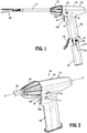
FIG. 1 is a side view illustrating a hand-held electromechanical surgical instrument including a handle assembly, with a power assembly shown separated, a shaft portion coupled to the handle assembly, and a surgical end effector coupled to the shaft portion; -
FIG. 2 is a partial perspective view illustrating a handle housing of the handle assembly ofFIG. 1 ; -
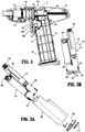
FIG. 3A is a perspective view, with parts separated, illustrating the power assembly ofFIG. 2 including a power assembly having an instrument module and an outer shell; -
FIG. 3B is an assembled front view illustrating the instrument module of the power assembly ofFIG. 3A ; -
FIG. 4 is a side view, with a housing half of the handle housing removed, illustrating internal components of the handle assembly; -
FIG. 5 is an enlarged side view, with a housing half of the handle housing and power assembly removed, illustrating internal components of the handle assembly ofFIG. 2 ; -
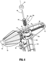
FIG. 6 is a partial perspective view, with parts separated, illustrating details of a rack and pinion assembly of the handle assembly ofFIG. 2 ; and -
FIG. 7 is a perspective view, with parts separated, illustrating details of the surgical end effector ofFIG. 1 . - Embodiments of the presently disclosed surgical instruments including handle assemblies thereof are described in detail with reference to the drawings, in which like reference numerals designate identical or corresponding elements in each of the several views. As used herein the term "distal" refers to that portion of the surgical instrument, or component thereof, farther from the user, while the term "proximal" refers to that portion of the surgical instrument, or component thereof, closer to the user.
- As will be described in detail below, provided is a handle assembly of a hand-held surgical instrument having a motor-driven pinion gear and a rack operably coupled to the gear. The rack is configured to carry out a function of a surgical end effector coupled to the handle assembly in response to an actuation of the motor. Further provided is an ergonomic, disposable handle housing and a reusable power assembly (e.g., an instrument module housed within a sterile or non-sterile outer casing). Other features and benefits of the disclosed surgical instruments are further detailed below.
- With reference to
FIGS. 1 and 2 , a surgical instrument, in accordance with an embodiment of the present disclosure, is generally designated as 10, and is in the form of a powered hand-held electromechanical surgical instrument configured for selective coupling thereto of a plurality of different surgical end effectors, for example, thesurgical end effector 200 ofFIGS. 1 and7 . Theend effector 200 is configured for actuation and manipulation by the powered hand-held electromechanical surgical instrument 10. The hand-held electromechanical surgical instrument 10 includes ahandle assembly 100, aknob housing 102 coupled to thehandle assembly 100, and ashaft portion 104 extending distally from theknob housing 102 and configured for selective connection with a surgical attachment, such as, for example, theend effector 200. - The
handle assembly 100 includes a disposable andsterile handle housing 110 having a body, such as, for example, abarrel portion 118, ahandle portion 108 extending perpendicularly downward from thebarrel portion 118 or transversely and proximally from thebarrel portion 118, and a hingeddoor 120 pivotably coupled to thehandle portion 108. Thedoor 120 is selectively opened and closed to allow for the insertion or removal of anon-sterile power assembly 122. Thehandle portion 108 and thedoor 120 each have an inner periphery collectively defining a sterile barrier 117 (FIG. 4 ) for thepower assembly 122 upon closing thedoor 120. In aspects, a proximal end portion or any suitable location of thebarrel portion 118 may have a clear window (not shown) to allow for viewing of a display (e.g., an LCD, not shown). - The
handle assembly 100 has afire switch 106 configured and adapted to actuate the various functions of theend effector 200. Thefire switch 106 may be constructed as a toggle bar pivotably coupled to thehandle portion 108 of thehandle housing 110. An activation of thefire switch 106 activates a motor 112 (FIGS. 3A and 3B ) to advance or retract a firing rod (not explicitly shown) of the surgical instrument 10 depending on whether atop button 106a or abottom button 106b of thefire switch 106 is actuated. The firing rod is coupled to a drive assembly 209 (FIG. 7 ) of the end effector 200 (which includes aknife rod 211 and an actuation sled 213), such that advancement of the firing rod advances thedrive assembly 209 of theend effector 200, which closes thejaw members end effector 200 and fires theend effector 200 when asafety switch 116 is in an actuated state. - The
handle assembly 100 has anarticulation switch 114 extending transversely through thehandle portion 108 and protruding outwardly from left and right sides of thehandle portion 108. Thearticulation switch 114 is configured to actuate an articulation of the end effector 200 (e.g., move theend effector 200 along a horizontal plane between a position coaxial with theshaft portion 104 and multiple positions out of alignment with the shaft portion 104). Theknob housing 102 is rotatably coupled to thehandle housing 110 and has theshaft portion 104 non-rotationally coupled thereto. As such, a manual rotation of theknob housing 102 results in a corresponding rotation of the end effector 200 (e.g., theend effector 200 rotates about a central longitudinal axis "X" defined by the shaft portion 104). A wave spring 121 (FIG. 4 ) provides resistance to inadvertent rotation of theknob housing 102. - The
handle assembly 100 may further include asafety switch 116 constructed as a tactile switch extending transversely through thebarrel portion 118 of thehandle housing 110. Thesafety switch 116 has opposing end portions exposed from an outer surface of thehandle housing 110 to allow a clinician to slide thesafety switch 116 between a firing-disabled position and a firing-enabled position. In the firing-disabled position, thesafety switch 116 one of contacts or disengages a contact switch 124 (FIG. 4 ) on a printed circuit board 126 (FIG. 4 ) of thehandle assembly 100, whereby aprocessor 136 of thepower assembly 122 is signaled to prevent an activation of themotor 112 notwithstanding an actuation of thefire switch 106. In the firing-enabled position, thesafety switch 116 contacts or disengages thecontact switch 124, whereby theprocessor 136 is signaled to allow an activation of themotor 112 upon actuating thefire switch 106. In aspects, thesafety switch 116 may have a light therein configured to blink or remain on in a steady state to indicate the position of thesafety switch 116. - In some embodiments, the
switches handle assembly 100 may be assigned to actuate various functions to be carried out by various surgical end effectors. It is contemplated that theswitches - With reference to
FIGS. 1 ,3A, 3B, and 4 , thereusable power assembly 122 of thehandle assembly 100 includes a sterileouter shell 128 and areusable instrument module 130 configured for removably receipt in theouter shell 128. Theouter shell 128 has acover 132 received in an open bottom end of theouter shell 128, and a spring-loadedpull tab 134 to facilitate removal of thecover 132. Theinstrument module 130 includes themotor 112, such as, for example, an electrical drive motor, which is electrically connected or wirelessly connected to the motor controller orprocessor 136 and abattery 138. In aspects, thebattery 138 may include a boost circuit and may be rechargeable (e.g., wirelessly). Thebattery 138 has acard edge connector 140 configured for detachable receipt of acard edge header 142 of the printedcircuit board 126 to allow for communication from thefire switch 106, thesafety switch 116, thearticulation switch 114, and an articulation encoder to thebattery 138. Theprocessor 136 may include aUSB charging connector 144 to allow for thebattery 138 to be recharged with a USB charger or wirelessly (e.g., via induction). - The
instrument module 130 further includes agearbox 146, such as, for example, a planetary gearbox, operably coupled to thedrive motor 112, and anoutput gear 148, such as, for example, a pinion gear, drivingly coupled to thegearbox 146 and configured to rotate about a longitudinal axis defined by thegearbox 146. Theplanetary gearbox 146 multiplies torque while reducing speed. - All components of the
instrument module 130 other than an upper portion of theplanetary gear box 146 and thepinion gear 148 are concealed within theouter shell 128. Rotation of thepinion gear 148 by themotor 112 functions to drive shafts and/or gear components of thehandle assembly 100 in order to perform the various operations of the end effector 200 (FIG. 7 ). For example, themotor 112 is configured to movejaw members 206, 208 (FIG. 7 ) of theend effector 200 relative to one another and to fire staples from theend effector 200. - With reference to
FIGS. 4-6 , thehandle assembly 100 includes aninner housing 150 and a rack andpinion assembly 152. Theinner housing 150 of thehandle assembly 100 is fixed within thebarrel portion 118 of thehandle housing 110 and includes atop end portion 150a and abottom end portion 150b. Theinner housing 150 defines afirst channel 154 extending vertically through the upper andlower end portions first channel 154 may have a cylindrical configuration or any other suitable shape to allow for rotation therein of anidler pinion gear 160 of the rack andpinion assembly 152. Theinner housing 150 further defines asecond channel 156 extending horizontally through theupper end portion 150a thereof. Thesecond channel 156 may have a rectangular shape or any other suitable shape to allow for translation therethrough of arack 162 of the rack andpinion assembly 152. Thesecond channel 156 is in communication with thefirst channel 154, such that theidler pinion gear 160 andrack 162 can engage one another. - The rack and
pinion assembly 152 further includes acap 164 fixed to theupper end portion 150a of theinner housing 150 and apin 166 fixed to thecap 164 and extending through thefirst channel 154 of theinner housing 150. Theidler pinion gear 160 is located about thepin 166 and is received in thefirst channel 154 of theinner housing 150. Theidler pinion gear 160 has anupper end portion 160a and abottom end portion 160b monolithically formed with or integrally connected to one another. Thebottom end portion 160b of theidler pinion gear 160 is configured to protrude beyond thebottom end portion 150b of theinner housing 150 to selectively engage the output pinion gear 148 (FIGS. 3A and 3B ) of theinstrument module 130 when thepower assembly 122 is received in thehandle portion 108 of thehandle housing 110. Thetop end portion 160a of theidler pinion gear 160 is located in theupper end portion 150a of theinner housing 150 and is engaged with teeth of therack 162. - The
idler pinion gear 160 defines anannular recess 170 between the upper andlower end portions annular recess 170 receives an O-ring seal 172 (FIG. 5 ) therein. The O-ring seal 172 is captured in an inner annular groove (not explicitly shown) defined in theinner housing 150. Theidler pinion gear 160 is axially supported in thefirst channel 154 of theinner housing 150 while for rotation of theidler pinion gear 160 in thefirst channel 154 of theinner housing 150. - The
rack 162 of the rack andpinion assembly 152 is disposed in thebarrel portion 118 of thehandle housing 110 and extends parallel with thebarrel portion 118. Therack 162 extends through thesecond channel 156 of theinner housing 150 and has a distal end portion (not explicitly shown) configured to operably couple to the drive assembly 209 (FIG. 7 ) of theend effector 200. Therack 162 is operably coupled to the output pinion gear 148 (FIGS. 3A and 3B ) via theupper end portion 160a of theidler pinion gear 160. In aspects, therack 162 may be directly engaged to theoutput pinion gear 148. - With reference to
FIG. 7 , theend effector 200 may be configured to be coupled to a distal end of theshaft portion 104 of the surgical instrument 10. Theend effector 200 includes aproximal body portion 202 and atool assembly 204. Theproximal body portion 202 is releasably attached to thehandle portion 102 and thetool assembly 204 is pivotally attached to a distal end of theproximal body portion 202 of theend effector 200. Theproximal body portion 202 is configured to articulate relative to the distal end of theshaft portion 102 via actuation of an articulation motor 113 (FIG. 4 ) and an associatedarticulation assembly 115. A flex circuit coil 119 (FIG. 6 ) is coupled to thearticulation motor 113 to maintain electrical communication between thearticulation motor 113 and the printedcircuit board 126 while allowing for rotation of theknob housing 102. Thetool assembly 204 includes ananvil assembly 206 and acartridge assembly 208. Thecartridge assembly 208 is pivotal in relation to theanvil assembly 206 and is movable between an open or unclamped position and a closed or clamped position for insertion through a cannula of a trocar. - For a detailed discussion of the construction and operation of the
surgical end effector 200, as illustrated inFIGS. 1 and7 , reference may be made toU.S. Patent No. 7,819,896, filed on August 31, 2009 , entitled "TOOL ASSEMBLY FOR A SURGICAL STAPLING DEVICE," the entire contents of which being incorporated by reference herein. - In operation, the
power assembly 122 is inserted into thehandle portion 108 of thehandle housing 110 and thedoor 120 is closed, thereby sealing thenon-sterile power assembly 122 in thesterile handle portion 108. Thecard edge head 142 of the printedcircuit board 126 is connected to thecard edge connector 140 of theinstrument module 130. Upon properly inserting thepower assembly 122, theoutput pinion gear 148 of theinstrument module 130 meshingly engages thebottom end portion 160b of theidler pinion gear 160. - To operate the
surgical end effector 200, thefire switch 106 may be toggled, whereby thebattery 138 provides power to themotor 112, which drives a rotation of theoutput pinion gear 148 via thegearbox 146. As theoutput pinion gear 112 rotates in a first direction, theidler pinion gear 148 rotates in an opposite second direction, to translate therack 162 along the longitudinal axis of thebarrel portion 118 of thehandle housing 110. Since therack 162 is operably coupled to thedrive assembly 209 of thesurgical end effector 200, translation of therack 162 results in one of an opening or closing of thejaw members rack 162. To fire staples from thesurgical end effector 200, thesafety switch 116 is actuated, and then thebottom button 106b of thefire switch 106 is actuated, whereby thesled 213 of thesurgical end effector 200 translates through thecartridge assembly 208 to fire the staples into tissue. - Any of the components described herein may be fabricated from either metals, plastics, resins, composites or the like taking into consideration strength, durability, wearability, weight, resistance to corrosion, ease of manufacturing, cost of manufacturing, and the like. Any of the gears disclosed herein may be configured as any suitable gear, such as bevel gears, spur gears, spiral gears, worm gears, or the like.
- It will be understood that various modifications may be made to the embodiments of the presently disclosed surgical instruments including switch assemblies. Therefore, the above description should not be construed as limiting, but merely as exemplifications of embodiments. Those skilled in the art will envision other modifications within the scope and spirit of the present disclosure.
- The invention may be described by reference to the following numbered paragraphs:-
- 1. A handle assembly of a hand-held surgical instrument, comprising:
- a handle housing;
- a rack supported in the handle housing and axially movable within the handle housing, the rack configured to operably couple to a driven member of a surgical end effector;
- an inner housing located within the handle housing; and
- an idler pinion gear supported in the inner housing and operably coupled to the rack, wherein the idler pinion gear is configured to translate the rack.
- 2. The handle assembly according to paragraph 1, wherein the handle housing includes a barrel portion, and a handle portion extending transversely and proximally from the barrel portion.
- 3. The handle assembly according to paragraph 2, wherein the rack is located in the barrel portion and defines a longitudinal axis that is parallel with a longitudinal axis defined by the barrel portion.
- 4. The handle assembly according to paragraph 1, wherein the idler pinion gear includes an upper end portion engaged with the rack, and a lower end portion.
- 5. The handle assembly according to paragraph 4, wherein the idler pinion gear defines a recess located between the upper and lower end portions, the idler pinion gear having an O-ring seal located in the recess.
- 6. The handle assembly according to paragraph 5, wherein the idler pinion gear is rotatable relative to and within the inner housing.
- 7. The handle assembly according to paragraph 4, wherein the lower end portion of the idler pinion gear protrudes from the inner housing.
- 8. The handle assembly according to paragraph 7, further comprising:
- a motor configured to be located within the handle housing; and
- a pinion gear operably coupled to the motor and configured to engage the lower end portion of the idler pinion gear.
- 9. The handle assembly according to paragraph 1, wherein the inner housing defines a first longitudinally-extending channel, the rack extending through the first channel.
- 10. The handle assembly according to paragraph 9, wherein the inner housing defines a second channel extending transversely relative to the first channel and in communication with the first channel, the idler pinion gear received in the second channel.
- 11. A hand-held surgical instrument, comprising:
- a handle housing;
- an instrument module configured for receipt in the handle housing and including:
- a motor; and
- a gear operably coupled to the motor; and
- a rack supported in the handle housing and axially movable within the handle housing, the rack configured to operably couple to a driven member of a surgical end effector, wherein the gear is configured to operable couple to the rack, such that a rotation of the gear results in a translation of the rack.
- 12. The hand-held surgical instrument according to paragraph 11, further comprising an outer shell configured for receipt in the handle housing, wherein the outer shell houses the instrument module therein.
- 13. The hand-held surgical instrument according to paragraph 11, further comprising an inner housing located within the handle housing, the inner housing defining a first channel having the rack extending therethrough.
- 14. The hand-held surgical instrument according to paragraph 13, further comprising an idler pinion gear supported in a second channel of the inner housing and operably coupled to the rack, wherein the idler pinion gear is configured to translate the rack in response to a rotation of the gear of the instrument module.
- 15. The hand-held surgical instrument according to paragraph 11, wherein the handle housing includes a barrel portion, and a handle portion extending transversely and proximally from the barrel portion.
- 16. The hand-held surgical instrument according to paragraph 15, wherein the rack is located in the barrel portion and defines a longitudinal axis that is parallel with a longitudinal axis defined by the barrel portion.
- 17. The hand-held surgical instrument according to paragraph 11, further comprising an idler pinion gear including an upper end portion engaged with the rack, and a lower end portion configured to engage the gear of the instrument module.
- 18. The hand-held surgical instrument according to paragraph 17, wherein the idler pinion gear defines a recess located between the upper and lower end portions, the idler pinion gear having an O-ring seal located in the recess.
- 19. The hand-held surgical instrument according to paragraph 11, wherein the instrument module further includes a battery for powering the motor.
- 20. The hand-held surgical instrument according to paragraph 19, further comprising:
- a button movably coupled to the handle housing; and
- a printed circuit board, the button associated with the printed circuit board, and the battery detachably coupled to the printed circuit board, such that an actuation of the button activates the battery.
Claims (14)
- A handle assembly of a hand-held surgical instrument, comprising:a handle housing;a rack supported in the handle housing and axially movable within the handle housing, the rack configured to operably couple to a driven member of a surgical end effector;an inner housing located within the handle housing; andan idler pinion gear supported in the inner housing and operably coupled to the rack, wherein the idler pinion gear is configured to translate the rack.
- The handle assembly according to claim 1, wherein the handle housing includes a barrel portion, and a handle portion extending transversely and proximally from the barrel portion; preferably wherein the rack is located in the barrel portion and defines a longitudinal axis that is parallel with a longitudinal axis defined by the barrel portion.
- The handle assembly according to any preceding claim, wherein the idler pinion gear includes an upper end portion engaged with the rack, and a lower end portion; preferably wherein the idler pinion gear defines a recess located between the upper and lower end portions, the idler pinion gear having an O-ring seal located in the recess.
- The handle assembly according to claim 3, wherein the idler pinion gear is rotatable relative to and within the inner housing; preferably wherein the lower end portion of the idler pinion gear protrudes from the inner housing.
- The handle assembly according to claim 4, further comprising:a motor configured to be located within the handle housing; anda pinion gear operably coupled to the motor and configured to engage the lower end portion of the idler pinion gear.
- The handle assembly according to any preceding claim, wherein the inner housing defines a first longitudinally-extending channel, the rack extending through the first channel; preferably wherein the inner housing defines a second channel extending transversely relative to the first channel and in communication with the first channel, the idler pinion gear received in the second channel.
- A hand-held surgical instrument, comprising:a handle housing;an instrument module configured for receipt in the handle housing and including:a motor; anda gear operably coupled to the motor; anda rack supported in the handle housing and axially movable within the handle housing, the rack configured to operably couple to a driven member of a surgical end effector, wherein the gear is configured to operable couple to the rack, such that a rotation of the gear results in a translation of the rack.
- The hand-held surgical instrument according to claim 7, further comprising an outer shell configured for receipt in the handle housing, wherein the outer shell houses the instrument module therein.
- The hand-held surgical instrument according to claim 7 or claim 8, further comprising an inner housing located within the handle housing, the inner housing defining a first channel having the rack extending therethrough' preferably further comprising an idler pinion gear supported in a second channel of the inner housing and operably coupled to the rack, wherein the idler pinion gear is configured to translate the rack in response to a rotation of the gear of the instrument module.
- The hand-held surgical instrument according to any of claims 7 to 9, wherein the handle housing includes a barrel portion, and a handle portion extending transversely and proximally from the barrel portion. preferably wherein the rack is located in the barrel portion and defines a longitudinal axis that is parallel with a longitudinal axis defined by the barrel portion.
- The hand-held surgical instrument according to any of claims 7 to 10, further comprising an idler pinion gear including an upper end portion engaged with the rack, and a lower end portion configured to engage the gear of the instrument module.
- The hand-held surgical instrument according to claim 11, wherein the idler pinion gear defines a recess located between the upper and lower end portions, the idler pinion gear having an O-ring seal located in the recess.
- The hand-held surgical instrument according to any of claims 7 to 12, wherein the instrument module further includes a battery for powering the motor.
- The hand-held surgical instrument according to claim 13, further comprising:a button movably coupled to the handle housing; anda printed circuit board, the button associated with the printed circuit board, and the battery detachably coupled to the printed circuit board, such that an actuation of the button activates the battery.
Applications Claiming Priority (2)
| Application Number | Priority Date | Filing Date | Title |
|---|---|---|---|
| US201962944400P | 2019-12-06 | 2019-12-06 | |
| US17/089,789 US11395655B2 (en) | 2019-12-06 | 2020-11-05 | Hand-held surgical instruments |
Publications (2)
| Publication Number | Publication Date |
|---|---|
| EP3831313A2 true EP3831313A2 (en) | 2021-06-09 |
| EP3831313A3 EP3831313A3 (en) | 2021-07-07 |
Family
ID=73726683
Family Applications (1)
| Application Number | Title | Priority Date | Filing Date |
|---|---|---|---|
| EP20211928.5A Pending EP3831313A3 (en) | 2019-12-06 | 2020-12-04 | Hand-held surgical instruments |
Country Status (4)
| Country | Link |
|---|---|
| US (1) | US11395655B2 (en) |
| EP (1) | EP3831313A3 (en) |
| JP (1) | JP2021090740A (en) |
| CN (1) | CN112914643A (en) |
Families Citing this family (2)
| Publication number | Priority date | Publication date | Assignee | Title |
|---|---|---|---|---|
| US11871924B2 (en) | 2018-09-21 | 2024-01-16 | Covidien Lp | Hand-held surgical instruments |
| ES2938393B2 (en) * | 2022-04-11 | 2023-11-17 | Pacheco Luis Alonso | Portable actuator device of a medical instrument for taking biopsies and tissue extraction by hysteroscopy |
Citations (1)
| Publication number | Priority date | Publication date | Assignee | Title |
|---|---|---|---|---|
| US7819896B2 (en) | 2002-10-04 | 2010-10-26 | Tyco Healthcare Group Lp | Tool assembly for a surgical stapling device |
Family Cites Families (73)
| Publication number | Priority date | Publication date | Assignee | Title |
|---|---|---|---|---|
| GB1579715A (en) | 1977-03-12 | 1980-11-26 | Omron Tateisi Electronics Co | Contacless switch and method of making the same |
| US4803362A (en) | 1987-10-27 | 1989-02-07 | Labworks, Inc. | Electro-optically activated switch with tactile feedback |
| DE69029597T2 (en) | 1989-04-21 | 1997-07-17 | Shinko Electric Co Ltd | Method and device for preventing malfunction in contactless push-button switches |
| US5465895A (en) * | 1994-02-03 | 1995-11-14 | Ethicon Endo-Surgery, Inc. | Surgical stapler instrument |
| US5747953A (en) | 1996-03-29 | 1998-05-05 | Stryker Corporation | Cordless, battery operated surical tool |
| US6025683A (en) | 1998-12-23 | 2000-02-15 | Stryker Corporation | Motor control circuit for regulating a D.C. motor |
| US6517565B1 (en) | 1999-06-02 | 2003-02-11 | Power Medical Interventions, Inc. | Carriage assembly for controlling a steering wire steering mechanism within a flexible shaft |
| EP1313401A4 (en) | 2000-08-30 | 2006-09-20 | Cerebral Vascular Applic Inc | MEDICAL INSTRUMENT |
| KR100651963B1 (en) | 2000-09-08 | 2006-11-30 | 엘지전자 주식회사 | Solid State Rotary Switch Assemblies |
| US6960894B2 (en) | 2002-08-01 | 2005-11-01 | Stryker Corporation | Cordless, powered surgical tool |
| US6978921B2 (en) * | 2003-05-20 | 2005-12-27 | Ethicon Endo-Surgery, Inc. | Surgical stapling instrument incorporating an E-beam firing mechanism |
| CA2724284C (en) | 2003-06-17 | 2013-02-26 | Tyco Healthcare Group Lp | Surgical stapling device |
| US7914543B2 (en) | 2003-10-14 | 2011-03-29 | Satiety, Inc. | Single fold device for tissue fixation |
| US8968276B2 (en) | 2007-09-21 | 2015-03-03 | Covidien Lp | Hand held surgical handle assembly, surgical adapters for use between surgical handle assembly and surgical end effectors, and methods of use |
| US10588629B2 (en) | 2009-11-20 | 2020-03-17 | Covidien Lp | Surgical console and hand-held surgical device |
| US9055943B2 (en) | 2007-09-21 | 2015-06-16 | Covidien Lp | Hand held surgical handle assembly, surgical adapters for use between surgical handle assembly and surgical end effectors, and methods of use |
| US9113880B2 (en) | 2007-10-05 | 2015-08-25 | Covidien Lp | Internal backbone structural chassis for a surgical device |
| AU2006255303B2 (en) * | 2005-06-03 | 2011-12-15 | Covidien Lp | Battery powered surgical instrument |
| KR101397210B1 (en) | 2005-06-28 | 2014-05-21 | 스트리커 코포레이션 | Control assembly for a motorized surgical tool that contains a sensor that monitors the state of the motor rotor |
| KR200442312Y1 (en) | 2007-01-19 | 2008-10-29 | 우진전장 주식회사 | Elevator button with non-contact optical switch |
| WO2008147415A1 (en) | 2007-05-31 | 2008-12-04 | Cox Raleigh L | An optical switch |
| US9539061B2 (en) | 2007-07-25 | 2017-01-10 | Karl Storz Gmbh & Co. Kg | Medical manipulator and welding method |
| US7918230B2 (en) | 2007-09-21 | 2011-04-05 | Tyco Healthcare Group Lp | Surgical device having a rotatable jaw portion |
| EP3111854B1 (en) * | 2007-09-21 | 2021-01-20 | Covidien LP | Surgical device |
| US10498269B2 (en) | 2007-10-05 | 2019-12-03 | Covidien Lp | Powered surgical stapling device |
| US8960520B2 (en) | 2007-10-05 | 2015-02-24 | Covidien Lp | Method and apparatus for determining parameters of linear motion in a surgical instrument |
| US7922063B2 (en) | 2007-10-31 | 2011-04-12 | Tyco Healthcare Group, Lp | Powered surgical instrument |
| CN101227187A (en) | 2008-02-04 | 2008-07-23 | 黄国芳 | Non contacting switch applied for automobile |
| US8584919B2 (en) | 2008-02-14 | 2013-11-19 | Ethicon Endo-Sugery, Inc. | Surgical stapling apparatus with load-sensitive firing mechanism |
| US10368838B2 (en) | 2008-03-31 | 2019-08-06 | Intuitive Surgical Operations, Inc. | Surgical tools for laser marking and laser cutting |
| US8608045B2 (en) * | 2008-10-10 | 2013-12-17 | Ethicon Endo-Sugery, Inc. | Powered surgical cutting and stapling apparatus with manually retractable firing system |
| US20100171026A1 (en) | 2009-01-07 | 2010-07-08 | Anywire Corporation | On/off switch |
| US8393516B2 (en) | 2009-02-26 | 2013-03-12 | Covidien Lp | Surgical stapling apparatus with curved cartridge and anvil assemblies |
| FR2948867B1 (en) * | 2009-08-06 | 2012-11-16 | Textile Hi Tec T H T | AGRAFE FOR MECHANICAL SUTURE |
| US8453906B2 (en) | 2010-07-14 | 2013-06-04 | Ethicon Endo-Surgery, Inc. | Surgical instruments with electrodes |
| CN102858225B (en) | 2010-07-29 | 2015-04-22 | 奥林巴斯医疗株式会社 | Medical instrument holding device |
| US8480703B2 (en) | 2010-11-19 | 2013-07-09 | Covidien Lp | Surgical device |
| CN103501965B (en) | 2011-03-31 | 2016-08-24 | 英格索尔-兰德公司 | The forward/reverse switching device of power tool |
| US10542978B2 (en) | 2011-05-27 | 2020-01-28 | Covidien Lp | Method of internally potting or sealing a handheld medical device |
| US8894647B2 (en) | 2012-01-13 | 2014-11-25 | Covidien Lp | System and method for performing surgical procedures with a reusable instrument module |
| US10080563B2 (en) | 2012-06-01 | 2018-09-25 | Covidien Lp | Loading unit detection assembly and surgical device for use therewith |
| US9868198B2 (en) | 2012-06-01 | 2018-01-16 | Covidien Lp | Hand held surgical handle assembly, surgical adapters for use between surgical handle assembly and surgical loading units, and methods of use |
| US9597104B2 (en) | 2012-06-01 | 2017-03-21 | Covidien Lp | Handheld surgical handle assembly, surgical adapters for use between surgical handle assembly and surgical end effectors, and methods of use |
| US9955965B2 (en) | 2012-07-09 | 2018-05-01 | Covidien Lp | Switch block control assembly of a medical device |
| US9700310B2 (en) | 2013-08-23 | 2017-07-11 | Ethicon Llc | Firing member retraction devices for powered surgical instruments |
| US9066710B2 (en) | 2012-10-19 | 2015-06-30 | St. Jude Medical, Cardiology Division, Inc. | Apparatus and method for heart valve repair |
| US9782187B2 (en) | 2013-01-18 | 2017-10-10 | Covidien Lp | Adapter load button lockout |
| CN203014768U (en) | 2013-01-24 | 2013-06-19 | 衢州昀睿工业设计有限公司 | Non-contact button switch for controlling work in positive direction and negative direction |
| US20140249557A1 (en) | 2013-03-01 | 2014-09-04 | Ethicon Endo-Surgery, Inc. | Thumbwheel switch arrangements for surgical instruments |
| US9888919B2 (en) | 2013-03-14 | 2018-02-13 | Ethicon Llc | Method and system for operating a surgical instrument |
| US9775610B2 (en) | 2013-04-09 | 2017-10-03 | Covidien Lp | Apparatus for endoscopic procedures |
| US9700318B2 (en) | 2013-04-09 | 2017-07-11 | Covidien Lp | Apparatus for endoscopic procedures |
| US9649110B2 (en) | 2013-04-16 | 2017-05-16 | Ethicon Llc | Surgical instrument comprising a closing drive and a firing drive operated from the same rotatable output |
| US9801646B2 (en) | 2013-05-30 | 2017-10-31 | Covidien Lp | Adapter load button decoupled from loading unit sensor |
| CN104224254B (en) | 2013-06-20 | 2016-03-30 | 瑞奇外科器械(中国)有限公司 | Surgical operating instrument and driving device thereof |
| US9351728B2 (en) | 2013-06-28 | 2016-05-31 | Covidien Lp | Articulating apparatus for endoscopic procedures |
| US9642620B2 (en) * | 2013-12-23 | 2017-05-09 | Ethicon Endo-Surgery, Llc | Surgical cutting and stapling instruments with articulatable end effectors |
| US9502192B2 (en) | 2014-02-14 | 2016-11-22 | Covidien Lp | Surgical instruments with non-contact switch assemblies |
| US10314577B2 (en) * | 2014-06-25 | 2019-06-11 | Ethicon Llc | Lockout engagement features for surgical stapler |
| US9693774B2 (en) * | 2014-06-25 | 2017-07-04 | Ethicon Llc | Pivotable articulation joint unlocking feature for surgical stapler |
| US20150374372A1 (en) | 2014-06-26 | 2015-12-31 | Covidien Lp | Hand held surgical handle assembly, surgical adapters for use between surgical handle assembly and surgical end effectors, and methods of use |
| US10111679B2 (en) | 2014-09-05 | 2018-10-30 | Ethicon Llc | Circuitry and sensors for powered medical device |
| US9991069B2 (en) | 2014-10-22 | 2018-06-05 | Covidien Lp | Surgical instruments and switch assemblies thereof |
| US9844375B2 (en) | 2014-12-18 | 2017-12-19 | Ethicon Llc | Drive arrangements for articulatable surgical instruments |
| US10085748B2 (en) * | 2014-12-18 | 2018-10-02 | Ethicon Llc | Locking arrangements for detachable shaft assemblies with articulatable surgical end effectors |
| US11154301B2 (en) * | 2015-02-27 | 2021-10-26 | Cilag Gmbh International | Modular stapling assembly |
| US10039532B2 (en) | 2015-05-06 | 2018-08-07 | Covidien Lp | Surgical instrument with articulation assembly |
| US11229471B2 (en) | 2016-01-15 | 2022-01-25 | Cilag Gmbh International | Modular battery powered handheld surgical instrument with selective application of energy based on tissue characterization |
| US10413291B2 (en) | 2016-02-09 | 2019-09-17 | Ethicon Llc | Surgical instrument articulation mechanism with slotted secondary constraint |
| US11484310B2 (en) | 2017-06-28 | 2022-11-01 | Cilag Gmbh International | Surgical instrument comprising a shaft including a closure tube profile |
| US10695060B2 (en) * | 2017-09-01 | 2020-06-30 | RevMedica, Inc. | Loadable power pack for surgical instruments |
| US11045270B2 (en) | 2017-12-19 | 2021-06-29 | Cilag Gmbh International | Robotic attachment comprising exterior drive actuator |
| AU2019228507B2 (en) | 2018-02-27 | 2025-01-02 | Applied Medical Resources Corporation | Surgical stapler having a powered handle |
-
2020
- 2020-11-05 US US17/089,789 patent/US11395655B2/en active Active
- 2020-12-03 CN CN202011405453.4A patent/CN112914643A/en active Pending
- 2020-12-03 JP JP2020200802A patent/JP2021090740A/en active Pending
- 2020-12-04 EP EP20211928.5A patent/EP3831313A3/en active Pending
Patent Citations (1)
| Publication number | Priority date | Publication date | Assignee | Title |
|---|---|---|---|---|
| US7819896B2 (en) | 2002-10-04 | 2010-10-26 | Tyco Healthcare Group Lp | Tool assembly for a surgical stapling device |
Also Published As
| Publication number | Publication date |
|---|---|
| US11395655B2 (en) | 2022-07-26 |
| EP3831313A3 (en) | 2021-07-07 |
| JP2021090740A (en) | 2021-06-17 |
| US20210169476A1 (en) | 2021-06-10 |
| CN112914643A (en) | 2021-06-08 |
Similar Documents
| Publication | Publication Date | Title |
|---|---|---|
| US11510669B2 (en) | Hand-held surgical instruments | |
| US11690618B2 (en) | Handheld electromechanical surgical instruments | |
| JP6882404B2 (en) | Handheld electromechanical surgery system | |
| CN101272740B (en) | surgical device | |
| US10918364B2 (en) | Intelligent adapter assembly for use with an electromechanical surgical system | |
| CN102176869B (en) | Electric surgical cutting and stapling device with manually retractable firing system | |
| US12274439B2 (en) | Hand-held surgical instruments | |
| US11395655B2 (en) | Hand-held surgical instruments | |
| CN114073555B (en) | Handheld surgical instruments | |
| EP4548861A1 (en) | Powered firing platform for linear surgical stapler | |
| CN117137561A (en) | Modularized electric anastomat |
Legal Events
| Date | Code | Title | Description |
|---|---|---|---|
| PUAI | Public reference made under article 153(3) epc to a published international application that has entered the european phase |
Free format text: ORIGINAL CODE: 0009012 |
|
| STAA | Information on the status of an ep patent application or granted ep patent |
Free format text: STATUS: THE APPLICATION HAS BEEN PUBLISHED |
|
| PUAL | Search report despatched |
Free format text: ORIGINAL CODE: 0009013 |
|
| AK | Designated contracting states |
Kind code of ref document: A2 Designated state(s): AL AT BE BG CH CY CZ DE DK EE ES FI FR GB GR HR HU IE IS IT LI LT LU LV MC MK MT NL NO PL PT RO RS SE SI SK SM TR |
|
| AK | Designated contracting states |
Kind code of ref document: A3 Designated state(s): AL AT BE BG CH CY CZ DE DK EE ES FI FR GB GR HR HU IE IS IT LI LT LU LV MC MK MT NL NO PL PT RO RS SE SI SK SM TR |
|
| RIC1 | Information provided on ipc code assigned before grant |
Ipc: A61B 17/072 20060101AFI20210601BHEP Ipc: A61B 17/00 20060101ALN20210601BHEP |
|
| STAA | Information on the status of an ep patent application or granted ep patent |
Free format text: STATUS: REQUEST FOR EXAMINATION WAS MADE |
|
| 17P | Request for examination filed |
Effective date: 20220104 |
|
| RBV | Designated contracting states (corrected) |
Designated state(s): AL AT BE BG CH CY CZ DE DK EE ES FI FR GB GR HR HU IE IS IT LI LT LU LV MC MK MT NL NO PL PT RO RS SE SI SK SM TR |
|
| STAA | Information on the status of an ep patent application or granted ep patent |
Free format text: STATUS: EXAMINATION IS IN PROGRESS |
|
| 17Q | First examination report despatched |
Effective date: 20241009 |