EP3829903B1 - Digital wheel end assembly temperature monitoring system - Google Patents
Digital wheel end assembly temperature monitoring system Download PDFInfo
- Publication number
- EP3829903B1 EP3829903B1 EP19843866.5A EP19843866A EP3829903B1 EP 3829903 B1 EP3829903 B1 EP 3829903B1 EP 19843866 A EP19843866 A EP 19843866A EP 3829903 B1 EP3829903 B1 EP 3829903B1
- Authority
- EP
- European Patent Office
- Prior art keywords
- temperature
- sensor
- wheel
- wheel end
- transmitter
- Prior art date
- Legal status (The legal status is an assumption and is not a legal conclusion. Google has not performed a legal analysis and makes no representation as to the accuracy of the status listed.)
- Active
Links
Images


Classifications
-
- B—PERFORMING OPERATIONS; TRANSPORTING
- B60—VEHICLES IN GENERAL
- B60B—VEHICLE WHEELS; CASTORS; AXLES FOR WHEELS OR CASTORS; INCREASING WHEEL ADHESION
- B60B27/00—Hubs
- B60B27/001—Hubs with roller-bearings
-
- B—PERFORMING OPERATIONS; TRANSPORTING
- B60—VEHICLES IN GENERAL
- B60B—VEHICLE WHEELS; CASTORS; AXLES FOR WHEELS OR CASTORS; INCREASING WHEEL ADHESION
- B60B27/00—Hubs
- B60B27/02—Hubs adapted to be rotatably arranged on axle
-
- B—PERFORMING OPERATIONS; TRANSPORTING
- B60—VEHICLES IN GENERAL
- B60C—VEHICLE TYRES; TYRE INFLATION; TYRE CHANGING; CONNECTING VALVES TO INFLATABLE ELASTIC BODIES IN GENERAL; DEVICES OR ARRANGEMENTS RELATED TO TYRES
- B60C23/00—Devices for measuring, signalling, controlling, or distributing tyre pressure or temperature, specially adapted for mounting on vehicles; Arrangement of tyre inflating devices on vehicles, e.g. of pumps or of tanks; Tyre cooling arrangements
- B60C23/001—Devices for manually or automatically controlling or distributing tyre pressure whilst the vehicle is moving
- B60C23/003—Devices for manually or automatically controlling or distributing tyre pressure whilst the vehicle is moving comprising rotational joints between vehicle-mounted pressure sources and the tyres
- B60C23/00309—Devices for manually or automatically controlling or distributing tyre pressure whilst the vehicle is moving comprising rotational joints between vehicle-mounted pressure sources and the tyres characterised by the location of the components, e.g. valves, sealings, conduits or sensors
- B60C23/00318—Devices for manually or automatically controlling or distributing tyre pressure whilst the vehicle is moving comprising rotational joints between vehicle-mounted pressure sources and the tyres characterised by the location of the components, e.g. valves, sealings, conduits or sensors on the wheels or the hubs
-
- B—PERFORMING OPERATIONS; TRANSPORTING
- B60—VEHICLES IN GENERAL
- B60C—VEHICLE TYRES; TYRE INFLATION; TYRE CHANGING; CONNECTING VALVES TO INFLATABLE ELASTIC BODIES IN GENERAL; DEVICES OR ARRANGEMENTS RELATED TO TYRES
- B60C23/00—Devices for measuring, signalling, controlling, or distributing tyre pressure or temperature, specially adapted for mounting on vehicles; Arrangement of tyre inflating devices on vehicles, e.g. of pumps or of tanks; Tyre cooling arrangements
- B60C23/001—Devices for manually or automatically controlling or distributing tyre pressure whilst the vehicle is moving
- B60C23/003—Devices for manually or automatically controlling or distributing tyre pressure whilst the vehicle is moving comprising rotational joints between vehicle-mounted pressure sources and the tyres
- B60C23/00309—Devices for manually or automatically controlling or distributing tyre pressure whilst the vehicle is moving comprising rotational joints between vehicle-mounted pressure sources and the tyres characterised by the location of the components, e.g. valves, sealings, conduits or sensors
- B60C23/00336—Devices for manually or automatically controlling or distributing tyre pressure whilst the vehicle is moving comprising rotational joints between vehicle-mounted pressure sources and the tyres characterised by the location of the components, e.g. valves, sealings, conduits or sensors on the axles
-
- B—PERFORMING OPERATIONS; TRANSPORTING
- B60—VEHICLES IN GENERAL
- B60C—VEHICLE TYRES; TYRE INFLATION; TYRE CHANGING; CONNECTING VALVES TO INFLATABLE ELASTIC BODIES IN GENERAL; DEVICES OR ARRANGEMENTS RELATED TO TYRES
- B60C23/00—Devices for measuring, signalling, controlling, or distributing tyre pressure or temperature, specially adapted for mounting on vehicles; Arrangement of tyre inflating devices on vehicles, e.g. of pumps or of tanks; Tyre cooling arrangements
- B60C23/001—Devices for manually or automatically controlling or distributing tyre pressure whilst the vehicle is moving
- B60C23/003—Devices for manually or automatically controlling or distributing tyre pressure whilst the vehicle is moving comprising rotational joints between vehicle-mounted pressure sources and the tyres
- B60C23/00345—Details of the rotational joints
-
- B—PERFORMING OPERATIONS; TRANSPORTING
- B60—VEHICLES IN GENERAL
- B60C—VEHICLE TYRES; TYRE INFLATION; TYRE CHANGING; CONNECTING VALVES TO INFLATABLE ELASTIC BODIES IN GENERAL; DEVICES OR ARRANGEMENTS RELATED TO TYRES
- B60C23/00—Devices for measuring, signalling, controlling, or distributing tyre pressure or temperature, specially adapted for mounting on vehicles; Arrangement of tyre inflating devices on vehicles, e.g. of pumps or of tanks; Tyre cooling arrangements
- B60C23/02—Signalling devices actuated by tyre pressure
- B60C23/04—Signalling devices actuated by tyre pressure mounted on the wheel or tyre
- B60C23/0408—Signalling devices actuated by tyre pressure mounted on the wheel or tyre transmitting the signals by non-mechanical means from the wheel or tyre to a vehicle body mounted receiver
-
- B—PERFORMING OPERATIONS; TRANSPORTING
- B60—VEHICLES IN GENERAL
- B60C—VEHICLE TYRES; TYRE INFLATION; TYRE CHANGING; CONNECTING VALVES TO INFLATABLE ELASTIC BODIES IN GENERAL; DEVICES OR ARRANGEMENTS RELATED TO TYRES
- B60C23/00—Devices for measuring, signalling, controlling, or distributing tyre pressure or temperature, specially adapted for mounting on vehicles; Arrangement of tyre inflating devices on vehicles, e.g. of pumps or of tanks; Tyre cooling arrangements
- B60C23/20—Devices for measuring or signalling tyre temperature only
-
- F—MECHANICAL ENGINEERING; LIGHTING; HEATING; WEAPONS; BLASTING
- F16—ENGINEERING ELEMENTS AND UNITS; GENERAL MEASURES FOR PRODUCING AND MAINTAINING EFFECTIVE FUNCTIONING OF MACHINES OR INSTALLATIONS; THERMAL INSULATION IN GENERAL
- F16C—SHAFTS; FLEXIBLE SHAFTS; ELEMENTS OR CRANKSHAFT MECHANISMS; ROTARY BODIES OTHER THAN GEARING ELEMENTS; BEARINGS
- F16C19/00—Bearings with rolling contact, for exclusively rotary movement
- F16C19/52—Bearings with rolling contact, for exclusively rotary movement with devices affected by abnormal or undesired conditions
- F16C19/525—Bearings with rolling contact, for exclusively rotary movement with devices affected by abnormal or undesired conditions related to temperature and heat, e.g. insulation
-
- F—MECHANICAL ENGINEERING; LIGHTING; HEATING; WEAPONS; BLASTING
- F16—ENGINEERING ELEMENTS AND UNITS; GENERAL MEASURES FOR PRODUCING AND MAINTAINING EFFECTIVE FUNCTIONING OF MACHINES OR INSTALLATIONS; THERMAL INSULATION IN GENERAL
- F16C—SHAFTS; FLEXIBLE SHAFTS; ELEMENTS OR CRANKSHAFT MECHANISMS; ROTARY BODIES OTHER THAN GEARING ELEMENTS; BEARINGS
- F16C2326/00—Articles relating to transporting
- F16C2326/01—Parts of vehicles in general
- F16C2326/02—Wheel hubs or castors
Definitions
- This application relates generally to wheel end temperature monitoring.
- US 2017/276570 A9 discloses a wireless sensor for a wheel end assembly of a heavy-duty vehicle.
- the wheel end assembly includes a wheel hub and a hub cap mounted on the wheel hub.
- the sensor includes mounting means disposed in the hub cap.
- Sensing means are mounted on the mounting means to sense at least one condition of the vehicle.
- a processor is mounted on the mounting means and is electrically connected to the sensing means to process data from the sensing means.
- Communication means are mounted on the mounting means and are electrically connected to the processor to communicate the processed data to a user.
- An electrical energy storage device is mounted on the mounting means and is electrically connected to the sensing means, the processor and the communication means, enabling the sensor to be independent from the vehicle power supply.
- the sensor also accommodates components of a tire inflation system.
- US 2005/052074 A1 discloses wheel end assembly rotatable on an axle on a vehicle having a high temperature warning system.
- An air pressure supply is positioned inside the axle and connected to a pressure source on the vehicle.
- a normally closed valve is connected to the axle between the inside and outside of the pressure supply.
- a heat sensitive control is connected to and actuates said valve upon a predetermined temperature.
- the control is mounted on the axle adjacent to the wheel end assembly for measuring the temperature of the assembly and axle.
- a warning system is connected to the pressure supply for actuation upon opening of the valves.
- the heat sensitive control includes a heat sensitive pressure barrier.
- a wheel end high-temperature warning system for a vehicle having a wheel-end assembly mounted to an axle.
- the system may include a temperature sensor including a sensor head configured for mounting at a spindle section of an axle near or in the wheel end assembly, the sensor head being in a heat exchange relationship with a bearing or other component of the wheel-end assembly.
- the system may further include a transmitter disposed on the axle to which the wheel-end assembly is mounted, the transmitter being configured to receive a sensor signal from the temperature sensor indicative of a wheel-end temperature and transmit the signal to a receiver.
- a vehicle data acquisition module may be coupled to the receiver, the data acquisition module being programmed to receive the sensor signal and process the signal to determine a temperature determined at the spindle.
- the vehicle data acquisition module may further include a display to provide a digital indication of the temperature and identify the particular wheel-end assembly associated with the temperature.
- the data acquisition module may further be configured to compare the detected temperature to a threshold temperature and to initiate one or more alarms if the temperature exceeds the threshold temperature.
- the transmitter may be configured to send a high-temperature alert to a driver mobile device or fleet operator computer or other recipient by text message or email when the temperature sensor detects a temperature above a temperature threshold.
- the temperature threshold may be a temperature past which the wheel end is at risk of fire or failure of components, such as bearing seals.
- One or more alerts or alarm faults may be initiated when one or more wheel-end assembly components reach a threshold temperature or other threshold condition.
- Systems herein may further identify characteristics of wheel end temperature associated with one or more alerts or alarm faults. For example, systems herein may be used to readily identify a particular wheel-end assembly initiating a fault, such as using an in-cab display included in a data acquisition module. Data acquisition modules herein may further provide an accurate digital reading of a measured temperature of the wheel end of a vehicle or component parts thereof.
- a plurality of temperature measurements may be made using temperature probes mounted at different positions within a wheel-end assembly of a vehicle. Such information may provide for a reliable warning of a high temperature condition. Additionally, diagnostic information may be accessed by a user and used to help diagnose whether any vehicle components may be damage, should any such damage have occurred.
- a sensor head of a an electrical temperature sensor may be positioned in contact with a component of a wheel-end assembly of a vehicle.
- the sensor head may route an electrical signal generated therein to circuitry of the sensor positioned away from or external to the wheel-end assembly.
- the electrical signal and a reference signal may then be used to generate a digital signal indicative of temperature.
- more than one sensing heads may be positioned on or near more than one component or region of a wheel-end assembly of a vehicle.
- each of a first sensor and a second sensor may be positioned within a wheel-end assembly of a vehicle. At least one of the first and second sensors may include a sensor head in a heat exchange relationship with the bearings of a wheel-end assembly.
- a vehicle 100 may comprise a truck 102 and a trailer 104.
- the truck 102 may include one or more drive axles 106 as part of the vehicle's powertrain.
- the truck 102 may further include a steer axle 114 having pivoting hubs that provide steering capability for the vehicle 100.
- the trailer 104 may include one or more fixed axles (not shown) and wheel ends.
- Each axle may have one or more wheels 108 mounted thereto with a tire 110 mounted to each wheel 108.
- other types of steerable vehicles such as cars and buses may be provided with the high temperature warning system disclosed herein.
- the vehicle 100 may be provided with a pressurized air supply (not shown) used to provide pressurized air to an optional automatic tire inflation system (indicated with air hoses 112 ).
- the high-temperature warning system (shown in more detail in FIGS. 3-19 ) may warn a driver when an axle 114 and/or axle wheel-end assembly reaches a predetermined temperature threshold or other threshold.
- a digital display of one or more measured temperatures, such as for a specific wheel-end assembly, may further be displayed.
- Such an axle and/or wheel-end assembly may be of a steerable or fixed configuration.
- a wheel-end assembly 2 (which may also be referred to herein as a wheel end) may be mounted to a spindle section 10 of an axle 12 and comprise a hub 4 , bearings 6 on which the hub may rotate around an axle, a brake drum 8 , a wheel (not shown) and a tire (not shown).
- the spindle 10 may be unsealed, or may be sealed at the time of manufacture, or may accept a plug 9 to seal the spindle.
- Plug 9 may, for example, be a press plug which may sealingly engage the inside of the axle 12 or spindle section 10 thereof and may be held in place by an interference fit without requiring additional mechanical means for locking the plug 9 in place.
- the plug 9 may provide a pressure barrier to contain the pneumatic pressure within the axle and may engage and support a stator of a rotary air connection, such as may be used in an automatic tire inflation system. Such an example of a rotary connection is described in more detail in connection with Fig. 15 .
- a wheel-end assembly may include a plug 9 that does not seal the axle 12.
- a plug 9 that is not required to seal an axle may also be referred to as a sensor mounting plate.
- a plug 9 (or sensor mounting plate) may be positioned within a spindle section 10 of an axle 12 and made of a material suitable to ensure that a sensor head mounted to the sensor mounting plate is in a heat exchange relationship with one or both of the bearings 6.
- a plug or mounting plate may be made of a carbon alloy steel or other suitable material and may be positioned approximate the bearings 6 . If the bearings 6 , brake drum 8 , or other wheel end component fail, then such failure may cause a high temperature event such that a tire or the wheel end lubricant may catch fire. In some instances, bearings have been known to reach a high enough temperature that the bearings melt. A wheel end temperature monitoring system may allow an operator to identify the onset of such a situation before such a critical hazard level is achieved at the wheel end.
- a wheel end temperature monitoring system 1 may comprise a first electrical temperature sensor or temperature transducer 14 disposed at or near the wheel end 2 and a transmitter 16 disposed on the axle 12 so as to monitor local temperatures in the wheel end 2 .
- the wheel end temperature monitoring system 1 may also include a receiver 15 and a dedicated vehicle data collection system or computer 19 coupled thereto.
- the data collection system or computer 19 may be specifically programmed to process one or more temperature signals, initiate one or more alerts or alarms and/or display temperature data.
- a temperature signal may also be conditioned so that a transmitter 16 may send the temperature signal to an otherwise programmable computer of a vehicle data collection system or other data collection system, such as may be external to a vehicle.
- the axle 12 may be sealed by a plug 9 so as to permit pressurization of the axle 12 for a tire inflation system.
- the temperature sensor 14 may be a thermocouple that is disposed in the plug 9 adjacent to the centerline of an outboard spindle face 18 so as to allow the rotary union 20 of a tire inflation system to be fitted at the centerline of the spindle face.
- temperature sensors such as thermocouples used herein may operate at relatively extreme temperatures and over an extended temperature range.
- the sensors shown in Figs. 4-6 may operate over a wide temperature range, such as a temperature range of about -40 degrees Celsius to about 1000 degrees Celsius.
- a temperature sensor 14 may be a thermocouple having a protective sheath 21 enclosing a pair of wires 23 .
- the pair of wires 23 may terminate at a sensor head 25 of the sensor 14 .
- the sensing head comprises dissimilar materials as is known in the thermocouple art.
- a thermo-electric current or voltage (which may be referred to as a thermo-electric signal) may be generated which depends on the composition of the two dissimilar materials and the temperature.
- the temperature sensor 14 may include also include a reference junction 26 , such as may include one or more component sensors for measurement of a reference temperature.
- a voltmeter 27 may be integrally included in the temperature sensor 14 or circuitry for voltage measurement may be externally coupled to the temperature sensor 14 .
- the sensor head 25 may include a threaded portion 33 to facilitate mounting of the sensor 14 .
- the sensor 14 may be attached to the spindle 10 or a plug or other wheel end component using a threaded portion 33 of the sensor head 25 .
- the protective sheath 21 may insulate the pair of wires 23 and protect components of the sensor 14 from wear.
- protective sheath 21 may be a highly durable and temperature resistant steel-braid to protect the pair of wires 23 , which may otherwise be subject to considerable friction and wear, particularly when the sensor head 25 is mounted within the spindle section 10 of an axle 12 and wherein at least a portion of the wires 23 may be otherwise be subject to severe conditions during vehicle operation.
- a temperature sensor 14 may include a sensor head 25 that is configured for mounting by use of a fastener.
- the sensor head 25 may include a ring eyelet 17 configured for mounting the sensor 14.
- a socket head cap screw 11 or other suitable screw or fastener may be inserted through the opening of the ring eyelet 17 and used for mounting the sensor 14 , such as to the spindle 10 (e.g., mounted to the spindle face 18 ) or to another wheel-end structure, such as a plug 9 (as also shown and in Fig. 3 ).
- wheel-end locations for mounting a sensor 14 may include the hub 4 , hub lugs, brake system body 8 , and a hubcap.
- a rotary electrical coupling may be used to connect the sensor head and transmitter by wired connection.
- a temperature sensor 14 may monitor the local temperature of a component to which the sensor is attached.
- a temperature sensor may contain more than one sensing head or probe. Thus, each of a plurality of sensing heads or probes may be inserted into an associated component for temperature monitoring. The temperature sensor may then monitor the internal temperature or adjacent temperature of more than one component or associated regions of a wheel end so as to provide a more accurate temperature profile of a desired region. For example, a difference in temperature between two or more components of a wheel end may provide for sensitive detection of a fault condition or otherwise serve other diagnostic functions, such as to indicate that one or more sensors or probes of a sensor may be damaged and need to be replaced.
- the system 1 may include a transmitter 16 electrically coupled to the temperature sensor 14 .
- Such coupling may be wired or wireless and may permit communication of a temperature signal from the temperature sensor to the transmitter 16 .
- a wired connection between the transmitter 16 and the temperature sensor 14 may be used when the transmitter 16 is attached to the axle 12 , or other suitable locations.
- the transmitter may be located near but outside of a wheel-end assembly, such as on the axle or another suitable location of a vehicle frame.
- a transmitter 16 may be integrally linked to the temperature sensor 14 , such as included in a common housing together with other components of the temperature sensor 14 .
- the transmitter 16 may be disposed on the axle 12 at a distance from the wheel-end assembly 2 such that heat generated therein does not pose a hazard to the electronics or housing of the transmitter 16 , thus avoiding potential damage from high wheel-end temperatures, mechanical impact and lubricants.
- the pair of wires 23 may be sized in length so as to enable positioning of the reference junction 26 at a suitable distance from the sensor head 25 .
- a reference junction 26 and voltage measurement circuitry e.g., voltmeter 27
- the transmitter 16 may be coupled to the axle 12 through a tapped hole in the axle or at or near the mid-point of a non-tapped bore into the axle.
- a threaded connection may be preferred for connecting the sensor 14 and transmitter 16 to the spindle and axle, other means of mechanically joining the components may be utilized. Welding, gluing, and strapping are some examples of possible coupling methods other than a threaded connection.
- a sensor head 25 may be attached to a wall of the spindle section 10 via a threaded connection and in some situations additionally glued or fixed therein so that a sensing junction of the head 25 is in intimate contact with the wall of the spindle section 10 .
- Such a connection may help to ensure that the sensor head 25 and thermo-electric junction therein are in a heat exchange relationship with the bearings 6 or other component of the wheel-end assembly.
- the transmitter 16 may be able to send collected signal data to a data acquisition module 19 of a wheel end high-temperature warning system.
- the data acquisition module 19 may be part of another vehicle data collection and/or processing system, such as a processing module for a tire inflation system.
- a data collection module 19 may be part of another data processing or collection system such as a tire pressure monitoring system, an anti-lock braking system (ABS), a telematics system, or other onboard or attached vehicle system.
- the transmitter 16 may also be shared among two or more different data collection systems.
- a transmitter 16 may include a processor, such as may include one or more memory buffers.
- the processor may, at least temporarily, store data from signals received from different vehicle systems and selectively send signals in a desired manner as may be needed for further processing.
- a processor may be programmed to direct transmission of temperature signal data at a predetermined rate or frequency. And, in some embodiments, that rate or frequency of transmission of temperature signal data may be adjusted based on characteristics of one or more input signals. For example, if a temperature signal is received from a temperature sensor 14, and the signal indicates that one or more wheel end components may be near a temperature limit, a rate of data transmission may be adjusted.
- a processor included in the transmitter 16 may be capable of performing at least a rudimentary analysis of signals to compare the signals to one or more specification limits.
- temperature data may be transmitted to the data acquisition module 19 at a low rate. If signal changes to indicate that the temperature of a wheel-end assembly may be closer to an alarm threshold, a rate of data transmission may be increased.
- either or both of receiver 15 and/or transmitter 16 may be configured for two-way communication.
- receiver 15 may be readily accessed by the data acquisition module 19 , which may include a more sophisticated processor for analysis of temperature data.
- Data acquisition module 19 may be configured to send a signal using receiver 15 (if appropriately configured for two-way communication) to instruct appropriately configured transmitter 16 to increase or decrease a rate of signal transmission.
- signal data may be selectively transmitted when one or more fault conditions may be most likely. Accordingly, energy used in transmission of signal data may be conserved.
- the transmitter 16 may have an internal power supply. Such a power supply may be a battery, dynamo, or other energy storage or energy producing device.
- the transmitter may communicate with the data collection system through a wireless protocol and methodology. Alternately, the transmitter may be powered by a separate power source through a wired connection.
- the transmitter 16 may be connected to the vehicle main electrical system or other vehicle sub-system to power the transmitter.
- Such sub-system may include but not be limited to an ABS, tire pressure monitoring system (TPMS), or other powered subsystem.
- An example of such a transmitter 16 may be a sensor-transmitter package from a TPMS that is adapted to collect the thermal data from the wheel end temperature sensor 14 .
- the adaptation may include the TPMS sensor package being reconfigured to accept temperature data rather than pressure data or the TPMS transmitter package may be reconfigured to accept both temperature and pressure data.
- Such a temperature adapted TPMS sensor may collect the temperature data and display the data, transmit the data to another module, or both display and transmit the data.
- FIG. 7 illustrates one embodiment of a view of the data display 600 of a TPMS sensor package, such as those carried by Truck System Technologies, adapted to collect and display both pressure and temperature data. The displayed data may be related to the particular wheel end and associated tire to which the sensor is mounted.
- a display 600 may include a diagram or schematic view 602 of a trailer.
- An individual tire or wheel end 604 may be emboldened or highlighted in some way, such as using dashed or broken lines or another suitable indicator.
- a toggle or selector button may be used to switch between tires or wheel ends.
- a display system may be configured to display an actual measured temperature 606 , provide an indication of whether the temperature is within a certain range (e.g., within a specification or normal range) or both.
- a certain range e.g., within a specification or normal range
- digital temperature data may be color coded or another indicator of a temperature range may be provided.
- a display may further provide a display 608 providing an indication of any active alarms or warnings
- the temperature sensor 14 and transmitter 16 may be in communication with one another by means of a wired connection 22 .
- wired connection 22 may comprise the pair of wires 23 or another connection may be used.
- the wired connection 22 may comprise a pair of wires 23 protected by a suitable protective sheathe 21 and routed through the interior of the spindle 10 and to axle 12 .
- the protective sheath may, for example, be a steel-braided protective sheath.
- the temperature monitoring system 1 may comprise a first temperature sensor 14 disposed through the wall of the spindle section 10 and a transmitter disposed on an axle 12 , such as through the wall of the axle 12 .
- a first temperature sensor 14 disposed through the wall of the spindle section 10 and a transmitter disposed on an axle 12 , such as through the wall of the axle 12 .
- the temperature sensor 14 may be disposed at the spindle 10 such that the sensor 14 is located at the interior of the hub 4 .
- the transmitter 16 may be disposed on the axle 12 such that the transmitter is substantially isolated from elevated temperatures resulting of the wheel end 2 .
- multiple temperature sensors may be coupled to a single transmitter.
- the transmitter may be configured to discriminate among multiple temperature sensor signals. Thus, if one of the multiple temperature sensors detects a high local temperature, the transmitter may transmit just the signal from that temperature sensor.
- the transmitter may send signals from all of the multiple temperature sensors, and the receiving system may determine which temperature sensor has provided the high temperature signal. More than one temperature sensor may be placed in a wheel-end assembly.
- a temperature fault may further be initiated based on a threshold difference in temperature between two or more sensors, a threshold rate of change of temperature for one or more sensor, or both.
- a steer axle 114 may be comprised of a wheel spindle 154 on which the wheel end assembly 156 may be mounted.
- the wheel end assembly 156 may include a hub (not shown) which may rotate on inner bearings 158 and outer bearings 178 .
- a wheel 108, tire 110 (as shown in FIG. 1 ), and hubcap may be mounted to the hub.
- a brake drum (not shown) may be integrally formed with the hub or otherwise mounted to the hub.
- a wheel end assembly 156 may contain other components, parts, or attachments that are not shown yet still monitored by the temperature monitoring system.
- the outer bearings 178 may be retained by a spindle nut 160 .
- a washer 162 may be mounted may between the spindle nut 160 and outer bearing 178 .
- a cotter pin 164 may be inserted through a receiving hole in the end of the wheel spindle so as to prevent the spindle nut 160 from becoming unscrewed.
- the spindle 154 may be pivotably mounted to the steer axle 114 via a knuckle post assembly (not shown).
- a hub cap (not shown) may be mounted to the hub so as to generally seal the bearings 158 and 178 from debris and prevent the loss of lubricant.
- a mounting block 252 may be disposed at the inboard or interior face 254 of the spindle 154 .
- a temperature sensor 256 such as a thermocouple, may be then be mounted at the block 252 .
- a temperature sensor 256 or sensing head of a sensor may be threaded and mate to a threaded hole in the block 252 .
- the sensor 256 may be welded, glued, epoxied, bolted, or otherwise mechanically mated to the block 252 .
- the block 252 may be positioned, sized, constructed, and/or bonded to the interior face 254 of the spindle to facilitate heat exchange between the block 252 and the bearings 158 .
- the mounting block 252 may be made of a material such as steel or brass.
- a temperature sensor 256 may be directly disposed at the interior face 254 of the spindle 154 such as in FIG. 11 .
- the sensor may be adhesively bonded to the face or may be threaded into a port that has been tapped into the spindle 154 .
- the sensor 256 may maintain a probe into the body of the spindle. While the centerline of the inner face 254 may be an ideal location for disposition of the sensor 256 when avoiding routing a wire through the body of the spindle, any location on any exterior face of the spindle may be suitable as allowed by differing wheel end and spindle designs and configurations.
- the wire 176 may be routed through the spindle to the axle through a channel cross-drilled in the spindle 154 , such as may be seen in Fig. 12 .
- a temperature sensor 256 may be disposed at the outboard end of the spindle 154 as in FIG. 13 or through the mid-body wall of the spindle 154 as in FIG. 14 . More than one temperature sensor may be placed in a wheel-end assembly.
- the disposition of the temperature sensor 256 may allow for the collection of direct thermal data pertaining to the spindle 154 and indirect thermal data for adjacent wheel end components.
- a temperature sensor 256 may be in wired communication with a transmitter (not shown) disposed on the axle as in previous embodiments.
- a wire 176 may be routed from the sensor to the transmitter through or around the knuckle post assembly and then the axle or other suitable routing path.
- a sensor 256 may be in wireless communication with a transmitter or a data collection module elsewhere on the vehicle.
- a steer axle temperature monitoring system may have a plurality of temperature sensors disposed at the spindle as seen in FIG. 15 .
- a first sensor 256A may be disposed at or through the outboard end of the spindle 154 while a second sensor 256B is disposed at a mounting block 252 on the inboard face 254 of the spindle 154 .
- the sensors may be in electronical communication with a transmitter (not shown in FIG. 15 ) to communicate collected temperature signal data to a vehicular data acquisition module.
- the vehicular data acquisition module may also collect and process data associated with one or more additional system such as an automatic tire inflation system or anti-lock brakes system.
- a wire 176 (which, as shown therein may comprise two or more component wires 176A, 176B) may maintain electronic communication between the first sensor 256A and second sensor 256B wherein the wire is disposed through the interior of the spindle body 154.
- a separate wire may be used to connect each of the first and second sensors to other components of a high temperature warning system.
- the first sensor 256A and second sensor 256B may be in wireless communication with one another and a vehicular data acquisition system.
- the transmitter may be configured to send a high-temperature alert to a driver mobile device or fleet operator computer or other recipient by text message or email when the temperature sensor detects a temperature above a temperature threshold.
- the temperature threshold may be a temperature past which the wheel end might risk fire or melting of components, such as bearing seals.
- a high-temperature warning system may receive temperature data from the transmitter, and may send such an alert to a driver or fleet operator.
- the high-temperature warning system may be configurable to provide more than one temperature threshold, depending on how many and where sensors are used for a wheel-end.
- the transmitter may trigger an in-cab alert (such as a sound, light, or message) if a dangerously high temperature is detected.
- the transmitter may be in communication with other components of a high-temperature warning system through wired or wireless connection. Any suitable wireless network may be used to send an alert.
- the transmitter may be a client device in a client-server network architecture, or may send temperature data to a client and/or server where such a network architecture is used for a high-temperature warning system.
- the transmitter may be configurable to recognize and adopt communication with one or more transducers, and to receive adjustable temperature warning threshold settings for each transducer. Each transducer may be individually coded to permit a high-temperature warning system to identify and depict on a graphical user interface the vehicle location and temperature reading of each transducer.
- a steer axle temperature monitoring system may have a plurality of temperature sensors disposed in the spindle as seen in FIG. 16 .
- a first sensor 256A may be disposed at or through the outboard end of the spindle 154 while a second sensor 256B is disposed through the mid-body wall of the spindle 154.
- the sensors may be in electronic communication with a transmitter (not shown) to communicate collected data to vehicular data acquisition systems, such as an automatic tire inflation system or anti-lock brakes.
- a wire 176 may maintain electronic communication between the first and second sensor wherein the wire is disposed through the interior of the spindle body 154.
- a strain relief sleeve or wire grommet 157 may also be provided to help protect the wire 176 from wear.
- the wire may also be connected to a vehicular data collection system.
- the first and second sensors may be in wireless communication with one another and a vehicular data acquisition system.
- a steer axle temperature monitoring system may have a plurality of temperature sensors disposed at the spindle as seen in FIG. 17 .
- a first sensor 256A may be disposed through the mid-body wall of the spindle 154 while a second sensor 256B is disposed at a mounting block 252 on the inboard face 254 of the spindle.
- the sensors may be in electronic communication with a transmitter (not shown) to communicate collected data with data acquisition systems, such as an automatic tire inflation system or anti-lock brakes.
- a wire 176 may maintain electronic communication between the first and second sensors wherein the wire is disposed through the interior of the spindle body 154 .
- the wire may also be connected to a vehicular data collection system.
- the first and second sensor may be in wireless communication with one another and a vehicular data acquisition system.
- Use of multiple sensors may permit calculation of a temperature gradient between sensors, and allow detection of the location and spread of high temperatures throughout the wheel end assembly.
- the wire may exit the body of the spindle at any point and then access a transmitter on the axle by means of cross-drilling the spindle as in the embodiment of FIG. 12 .
- the sensor head 28 and transmitter assembly 30 may be electrically linked by means of a wire 32 wherein the wire is disposed through the interior of an axle.
- the sensor head 28 may couple to the outboard end of a sealed spindle or a plug in the spindle, for example, as the case may be for a particular spindle design.
- the sensor head 28 may be disposed adjacent to a rotary union in such cases that a rotary union is present in a wheel end.
- the sensor head 28 may be on the exterior or interior face of the spindle such that the sensor resides at the exterior of the spindle or interior space of the spindle respectively.
- the transmitter assembly 30 may couple to an axle and be so disposed as prevent interference with other wheel end components.
- the transmitter assembly 30 may be located about 76.2 cm (30 inches) from the temperature sensor 28 .
- the transmitter assembly 30 may be located about 63.5 cm (25 inches) to about 101.6 cm (40 inches) from the transmitter or at the axle endpoint, approximately.
- Such a location may avoid interference with other vehicle components and provide a location sufficiently free from electronical or other interference for wireless communication between the transmitter 30 and any data collection systems of the vehicle.
- the transmitter assembly 30 may accept a wired connection to vehicle data collection systems.
- Such a wired connection may be realized through the use of a Deutsch connector(or other connector switchable for automotive use) at the transmitter to provide environmental protection for the wired connection point.
- the sensor 28 may be connected to a vehicle data collection system using a suitably weather tight connector.
- the transmitter assembly 30 may be an electronic device housed inside a protective body 34 with the body maintaining a mating lug 36 at the lower face of the body.
- a lug 36 may have a central passage through the lug so as to allow a wire 32 to pass from the electronic portion of the transmitter assembly 30 for connection to the associated sensor head 28.
- the lug may also have a faceted portion or washer 38 integrated into the lug 36 at the upper portion of the lug, such as where the lug 36 joins the protective body 34 of the transmitter assembly 30.
- Such a washer 38 may provide an appropriate section of the overall transmitter assembly 30 at which torque may be applied via a tool such as a wrench.
- the protective body 34 of the transmitter 30 may maintain a circumferential pattern of indentations 40. Such indentations 40 may allow a user to readily and adequately apply torque to the transmitter assembly 30 without the use of a tool.
- the transmitter assembly 30 may house a second temperature sensor or be adapted for use with a plurality of sensor heads.
- Both sensor head 28 and transmitter assembly 30 may be coupled to their respective section of the vehicle by means of a threaded connection.
- the sensor may be a thermocouple that threads into a port on a plug or spindle face, as the case may be, while the transmitter body maintains a threaded lug that mates to a port in the axle.
- both sensor head 28 and transmitter assembly 30 may be sealed so as to provide environmental protection for the electronic electrically sensitive components or elements of each.
- the temperature sensor 256 may be disposed inside of a hubcap 42 .
- the sensor may be located at the interior face of the hubcap of the outboard wall 44 of the hubcap as in FIG. 19 or at the interior face of the side wall 46 of the hubcap as in FIG. 20 .
- the sensor 256 may be threaded into the wall of the hubcap or may be surface mounted to the wall.
- a wire 47 may be routed through the interior of the hubcap and through the wheel end 2 and further through the axle 12 to a transmitter (not shown) disposed further down the length of the axle.
- a rotary electrical connection (not shown), such as a slip ring, may be used to provide an electrical path from a rotating part to a stationary part of the wheel end.
- the temperature sensor may be utilized in a hubcap and wheel end containing a tire inflation system 48 . Such co-usage of the two systems may be realized by routing the wire 48 adjacent to a rotary union 50 of the inflation system.
- a temperature sensor 256 may be mounted to a hubcap 42 with an associated transmitter 52 also mounted at the hubcap.
- the sensor 256 may be disposed at the interior face of the hubcap 42 while the transmitter 52 is disposed at the exterior face of the hubcap.
- the transmitter and sensor components may be of a unitary design or the transmitter and sensor may be separate components in electrical communication by means of an interconnecting wire.
- a temperature sensor and a transmitter may be separate components linked by a wire.
- the temperature sensor may be disposed at the interior face of a hubcap in the vicinity adjacent to the wheel end so as to capture as accurate useful data.
- the sensor may be threaded into the wall of the hubcap or otherwise mechanically attached to the hubcap.
- a wire 47 may link the sensor to a transmitter 56 so as to maintain electrical communication between the components.
- FIG. 22 A unitary design is illustrated in FIG. 22 .
- a threaded body 54 of the temperature sensor 256 may be directly attached to a housing 56 in which are disposed the electronic components of the transmitter component.
- a visual display may also be incorporated into the housing to visually communicate the temperature data.
- the transmitter 52 may collect and disseminate temperature data solely or may also collect and disseminate tire pressure data in conjunction with wheel end temperature data.
- An embodiment that collects both temperature and pressure data may reflect a temperature sensor combined with a TPMS sensor as previously described.
- FIG. 23 shows an embodiment of a method 400 of installing a high temperature warning system.
- a hole may be drilled into an axle.
- some axles may include one or more existing holes or dedicated access points.
- some axles may include or be tapped to include a 6.35 mm (1 ⁇ 4 inch) National Standard Pipe Thread (NPT) hole.
- NPT National Standard Pipe Thread
- a wire such as may be steel braided protective sheath 21 may be threaded through the tapped hole and routed through the axle.
- a sensor head may be attached to the wire (and threaded along with the wire) or the wire may be attached to the sensor head after threading the wire, depending on the particular design of the sensor.
- a sensor head may be inserted into or through either of a plug or sensor mounting plate.
- the sensor head may be installed into a hole, such as may be drilled into a face of a spindle or other wheel end component.
- the plug (or mounting plate) may be attached within the spindle (or other wheel end component).
- a plurality of sensors may be employed such that any particular area or component of the wheel end, wherein the capture of temperature data is of benefit, may have a sensor disposed at the desired location.
- thermocouple as a temperature sensor
- other electrical temperature sensors may also be utilized.
- Such other types of sensors may include, but not be limited to, thermistors, resistance temperature detectors such as resistance thermometers silicon bandgap temperature sensors, and other temperature detection modalities or methodologies as may be known to one skilled in the art.
- the temperature sensors may be of contact or non-contact modalities.
- the temperature sensor may be combined with or co-located within a rotary union.
- a rotary union As many thermocouples have a probe extension on the thermocouple and many rotary unions rely on a stator that passes through the body to which the rotary union is attached, the probe and stator may be unified into a single body or a temperature probe may be attached to the stator.
- a combined thermocouple and rotary union may be interdisposed such that the probe of the thermocouple passes through the center opening of the rotary union.
Landscapes
- Engineering & Computer Science (AREA)
- Mechanical Engineering (AREA)
- General Engineering & Computer Science (AREA)
- Arrangements For Transmission Of Measured Signals (AREA)
- Rolling Contact Bearings (AREA)
Description
- This application relates generally to wheel end temperature monitoring.
- In the event of a failure associated with the wheel end, such as a bearing failure or brake failure, elements of the wheel end can reach high temperatures very quickly. Such high temperatures may cause tires and/or lubricant to ignite, resulting in wheel lock up or fire. Due to the intense heat caused by a wheel end failure, the wheel end may detach from the axle.
- There remains a need for a system for monitoring the wheel end assembly temperature and collecting data on the temperature for immediate and long-term evaluation.
-
US 2017/276570 A9 discloses a wireless sensor for a wheel end assembly of a heavy-duty vehicle. The wheel end assembly includes a wheel hub and a hub cap mounted on the wheel hub. The sensor includes mounting means disposed in the hub cap. Sensing means are mounted on the mounting means to sense at least one condition of the vehicle. A processor is mounted on the mounting means and is electrically connected to the sensing means to process data from the sensing means. Communication means are mounted on the mounting means and are electrically connected to the processor to communicate the processed data to a user. An electrical energy storage device is mounted on the mounting means and is electrically connected to the sensing means, the processor and the communication means, enabling the sensor to be independent from the vehicle power supply. The sensor also accommodates components of a tire inflation system. -
US 2005/052074 A1 discloses wheel end assembly rotatable on an axle on a vehicle having a high temperature warning system. An air pressure supply is positioned inside the axle and connected to a pressure source on the vehicle. A normally closed valve is connected to the axle between the inside and outside of the pressure supply. A heat sensitive control is connected to and actuates said valve upon a predetermined temperature. The control is mounted on the axle adjacent to the wheel end assembly for measuring the temperature of the assembly and axle. A warning system is connected to the pressure supply for actuation upon opening of the valves. The heat sensitive control includes a heat sensitive pressure barrier. - The invention is defined in claim 1. Further aspects and preferred embodiments of the invention are defined in the dependent claims. Any aspects, embodiments and examples of the present disclosure which do not fall under the scope of the appended claims are provided for illustrative purposes.
-
-
FIG. 1 illustrates a vehicle with a temperature monitoring system. -
FIG. 2 illustrates a fixed axle and wheel end with mounted sensors. -
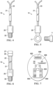
FIG. 3 illustrates a wheel end assembly including a high temperature warning system and other components that may be part of a high temperature warning system. - FIG. 3A illustrates a temperature sensor including a threaded temperature sensing head.
- FIG. 3B illustrates a temperature sensor including an eyelet and screw useful for fixing the temperature sensor to a wheel end component of a vehicle.
- FIG. 3C illustrates another embodiment of a temperature sensor.
- FIG. 3D illustrates an example of a visual display for pressure and temperature data.
-
FIG. 4 illustrates an embodiment of a fixed axle wheel end with a temperature sensor installed in the axle between the two wheel bearings. -
FIG. 5 illustrates a fixed axle wheel end with a single sensor configuration. -
FIG. 6 illustrates a fixed axle wheel end with an alternate sensor configuration and a probed sensor. -
FIG. 7 illustrates a fixed axle wheel end with another alternate sensor configuration and a probed sensor. -
FIG. 8 illustrates the components of a steer axle wheel end. -
FIG. 9 illustrates a steer axle wheel end with a sensor on a mounting block. -
FIG. 10 illustrates a steer axle wheel end with a sensor at the outboard face. -
FIG. 11 illustrates a steer axle wheel end with a sensor at the spindle mid-body. -
FIG. 12 illustrates a steer axle wheel end with a sensor at the inboard face and the outboard face. -
FIG. 13 illustrates a steer axle wheel end with a sensor at the spindle mid-body and the outboard face. -
FIG. 14 illustrates a steer axle wheel end with a sensor at the spindle mid-body and the inboard face. -
FIG. 15 illustrates an embodiment of a sensor and transmitter. -
FIG. 16 illustrates an embodiment of a hub cap mounted sensor. -
FIG. 17 illustrates an embodiment of a hub cap mounted sensor and transmitter. -
FIG. 18 illustrates yet another embodiment of a hub cap mounted sensor with an integrated transmitter. -
FIG. 19 illustrates another embodiment of a high-temperature warning system. - In some embodiments, a wheel end high-temperature warning system for a vehicle having a wheel-end assembly mounted to an axle is described. The system may include a temperature sensor including a sensor head configured for mounting at a spindle section of an axle near or in the wheel end assembly, the sensor head being in a heat exchange relationship with a bearing or other component of the wheel-end assembly. The system may further include a transmitter disposed on the axle to which the wheel-end assembly is mounted, the transmitter being configured to receive a sensor signal from the temperature sensor indicative of a wheel-end temperature and transmit the signal to a receiver. A vehicle data acquisition module may be coupled to the receiver, the data acquisition module being programmed to receive the sensor signal and process the signal to determine a temperature determined at the spindle. The vehicle data acquisition module may further include a display to provide a digital indication of the temperature and identify the particular wheel-end assembly associated with the temperature. The data acquisition module may further be configured to compare the detected temperature to a threshold temperature and to initiate one or more alarms if the temperature exceeds the threshold temperature. For example, the transmitter may be configured to send a high-temperature alert to a driver mobile device or fleet operator computer or other recipient by text message or email when the temperature sensor detects a temperature above a temperature threshold. The temperature threshold may be a temperature past which the wheel end is at risk of fire or failure of components, such as bearing seals.
- It is an objective of some embodiments herein to provide diagnostic information pertaining to the temperature of a wheel end assembly to a system user. For example, one or more alerts or alarm faults may be initiated when one or more wheel-end assembly components reach a threshold temperature or other threshold condition. Systems herein may further identify characteristics of wheel end temperature associated with one or more alerts or alarm faults. For example, systems herein may be used to readily identify a particular wheel-end assembly initiating a fault, such as using an in-cab display included in a data acquisition module. Data acquisition modules herein may further provide an accurate digital reading of a measured temperature of the wheel end of a vehicle or component parts thereof. In some embodiments, a plurality of temperature measurements may be made using temperature probes mounted at different positions within a wheel-end assembly of a vehicle. Such information may provide for a reliable warning of a high temperature condition. Additionally, diagnostic information may be accessed by a user and used to help diagnose whether any vehicle components may be damage, should any such damage have occurred.
- It is an objective of some embodiments herein to provide for an accurate measurement of temperature of components of a wheel-end assembly of a vehicle. In some of those embodiments, a sensor head of a an electrical temperature sensor may be positioned in contact with a component of a wheel-end assembly of a vehicle. The sensor head may route an electrical signal generated therein to circuitry of the sensor positioned away from or external to the wheel-end assembly. The electrical signal and a reference signal may then be used to generate a digital signal indicative of temperature. In some embodiments, more than one sensing heads may be positioned on or near more than one component or region of a wheel-end assembly of a vehicle. For example, each of a first sensor and a second sensor may be positioned within a wheel-end assembly of a vehicle. At least one of the first and second sensors may include a sensor head in a heat exchange relationship with the bearings of a wheel-end assembly.
- As may be seen in
FIG. 1 , avehicle 100 may comprise atruck 102 and atrailer 104. Thetruck 102 may include one ormore drive axles 106 as part of the vehicle's powertrain. Thetruck 102 may further include asteer axle 114 having pivoting hubs that provide steering capability for thevehicle 100. Thetrailer 104 may include one or more fixed axles (not shown) and wheel ends. Each axle may have one ormore wheels 108 mounted thereto with atire 110 mounted to eachwheel 108. Of course, other types of steerable vehicles, such as cars and buses may be provided with the high temperature warning system disclosed herein. - The
vehicle 100 may be provided with a pressurized air supply (not shown) used to provide pressurized air to an optional automatic tire inflation system (indicated with air hoses 112). The high-temperature warning system (shown in more detail inFIGS. 3-19 ) may warn a driver when anaxle 114 and/or axle wheel-end assembly reaches a predetermined temperature threshold or other threshold. A digital display of one or more measured temperatures, such as for a specific wheel-end assembly, may further be displayed. Such an axle and/or wheel-end assembly may be of a steerable or fixed configuration. - As may be seen in
FIGS. 2 and3 , a wheel-end assembly 2 (which may also be referred to herein as a wheel end) may be mounted to aspindle section 10 of anaxle 12 and comprise ahub 4,bearings 6 on which the hub may rotate around an axle, abrake drum 8, a wheel (not shown) and a tire (not shown). Thespindle 10 may be unsealed, or may be sealed at the time of manufacture, or may accept aplug 9 to seal the spindle.Plug 9 may, for example, be a press plug which may sealingly engage the inside of theaxle 12 orspindle section 10 thereof and may be held in place by an interference fit without requiring additional mechanical means for locking theplug 9 in place. Theplug 9 may provide a pressure barrier to contain the pneumatic pressure within the axle and may engage and support a stator of a rotary air connection, such as may be used in an automatic tire inflation system. Such an example of a rotary connection is described in more detail in connection withFig. 15 . Alternatively, a wheel-end assembly may include aplug 9 that does not seal theaxle 12. In this disclosure, aplug 9 that is not required to seal an axle may also be referred to as a sensor mounting plate. In some embodiments, a plug 9 (or sensor mounting plate) may be positioned within aspindle section 10 of anaxle 12 and made of a material suitable to ensure that a sensor head mounted to the sensor mounting plate is in a heat exchange relationship with one or both of thebearings 6. For example, a plug or mounting plate may be made of a carbon alloy steel or other suitable material and may be positioned approximate thebearings 6. If thebearings 6,brake drum 8, or other wheel end component fail, then such failure may cause a high temperature event such that a tire or the wheel end lubricant may catch fire. In some instances, bearings have been known to reach a high enough temperature that the bearings melt. A wheel end temperature monitoring system may allow an operator to identify the onset of such a situation before such a critical hazard level is achieved at the wheel end. - As may be seen in the embodiment of
Fig. 3 , a wheel end temperature monitoring system 1 may comprise a first electrical temperature sensor ortemperature transducer 14 disposed at or near thewheel end 2 and atransmitter 16 disposed on theaxle 12 so as to monitor local temperatures in thewheel end 2. In some embodiments, the wheel end temperature monitoring system 1 may also include areceiver 15 and a dedicated vehicle data collection system orcomputer 19 coupled thereto. The data collection system orcomputer 19 may be specifically programmed to process one or more temperature signals, initiate one or more alerts or alarms and/or display temperature data. A temperature signal may also be conditioned so that atransmitter 16 may send the temperature signal to an otherwise programmable computer of a vehicle data collection system or other data collection system, such as may be external to a vehicle. - In the embodiment shown in
Fig. 3 , theaxle 12 may be sealed by aplug 9 so as to permit pressurization of theaxle 12 for a tire inflation system. Thetemperature sensor 14 may be a thermocouple that is disposed in theplug 9 adjacent to the centerline of anoutboard spindle face 18 so as to allow therotary union 20 of a tire inflation system to be fitted at the centerline of the spindle face. Advantageously, temperature sensors such as thermocouples used herein may operate at relatively extreme temperatures and over an extended temperature range. For example, the sensors shown inFigs. 4-6 may operate over a wide temperature range, such as a temperature range of about -40 degrees Celsius to about 1000 degrees Celsius. - As shown in
Figs. 4-6 , atemperature sensor 14 may be a thermocouple having aprotective sheath 21 enclosing a pair ofwires 23. The pair ofwires 23 may terminate at asensor head 25 of thesensor 14. The sensing head comprises dissimilar materials as is known in the thermocouple art. A thermo-electric current or voltage (which may be referred to as a thermo-electric signal) may be generated which depends on the composition of the two dissimilar materials and the temperature. Thetemperature sensor 14 may include also include areference junction 26, such as may include one or more component sensors for measurement of a reference temperature. Avoltmeter 27 may be integrally included in thetemperature sensor 14 or circuitry for voltage measurement may be externally coupled to thetemperature sensor 14. - As shown in each of
FIG. 4 and FIG. 6 , thesensor head 25 may include a threadedportion 33 to facilitate mounting of thesensor 14. For example, thesensor 14 may be attached to thespindle 10 or a plug or other wheel end component using a threadedportion 33 of thesensor head 25. Theprotective sheath 21 may insulate the pair ofwires 23 and protect components of thesensor 14 from wear. For example,protective sheath 21 may be a highly durable and temperature resistant steel-braid to protect the pair ofwires 23, which may otherwise be subject to considerable friction and wear, particularly when thesensor head 25 is mounted within thespindle section 10 of anaxle 12 and wherein at least a portion of thewires 23 may be otherwise be subject to severe conditions during vehicle operation. - As shown in
FIG. 4 , atemperature sensor 14 may include asensor head 25 that is configured for mounting by use of a fastener. For example, thesensor head 25 may include aring eyelet 17 configured for mounting thesensor 14. A sockethead cap screw 11 or other suitable screw or fastener may be inserted through the opening of thering eyelet 17 and used for mounting thesensor 14, such as to the spindle 10 (e.g., mounted to the spindle face 18) or to another wheel-end structure, such as a plug 9 (as also shown and inFig. 3 ). Other wheel-end locations for mounting asensor 14, such as may be used to position a sensing head or probe region of thesensor 14 on or near a component for temperature monitoring, may include thehub 4, hub lugs,brake system body 8, and a hubcap. For mounting to wheel end components that rotate with respect to the axle, a rotary electrical coupling may be used to connect the sensor head and transmitter by wired connection. - A
temperature sensor 14 may monitor the local temperature of a component to which the sensor is attached. In some embodiments, a temperature sensor may contain more than one sensing head or probe. Thus, each of a plurality of sensing heads or probes may be inserted into an associated component for temperature monitoring. The temperature sensor may then monitor the internal temperature or adjacent temperature of more than one component or associated regions of a wheel end so as to provide a more accurate temperature profile of a desired region. For example, a difference in temperature between two or more components of a wheel end may provide for sensitive detection of a fault condition or otherwise serve other diagnostic functions, such as to indicate that one or more sensors or probes of a sensor may be damaged and need to be replaced. - The system 1 may include a
transmitter 16 electrically coupled to thetemperature sensor 14. Such coupling may be wired or wireless and may permit communication of a temperature signal from the temperature sensor to thetransmitter 16. For example, a wired connection between thetransmitter 16 and thetemperature sensor 14 may be used when thetransmitter 16 is attached to theaxle 12, or other suitable locations. Where a wireless link is established between thetransmitter 16 andtemperature sensor 14, the transmitter may be located near but outside of a wheel-end assembly, such as on the axle or another suitable location of a vehicle frame. In some embodiments, atransmitter 16 may be integrally linked to thetemperature sensor 14, such as included in a common housing together with other components of thetemperature sensor 14. Thetransmitter 16 may be disposed on theaxle 12 at a distance from the wheel-end assembly 2 such that heat generated therein does not pose a hazard to the electronics or housing of thetransmitter 16, thus avoiding potential damage from high wheel-end temperatures, mechanical impact and lubricants. In some embodiments, the pair ofwires 23 may be sized in length so as to enable positioning of thereference junction 26 at a suitable distance from thesensor head 25. For example, either or both of areference junction 26 and voltage measurement circuitry (e.g., voltmeter 27) may be positioned at a distance from the wheel-end assembly 2, such as onaxle 12. Thetransmitter 16 may be coupled to theaxle 12 through a tapped hole in the axle or at or near the mid-point of a non-tapped bore into the axle. - While a threaded connection may be preferred for connecting the
sensor 14 andtransmitter 16 to the spindle and axle, other means of mechanically joining the components may be utilized. Welding, gluing, and strapping are some examples of possible coupling methods other than a threaded connection. For example, in some embodiments, asensor head 25 may be attached to a wall of thespindle section 10 via a threaded connection and in some situations additionally glued or fixed therein so that a sensing junction of thehead 25 is in intimate contact with the wall of thespindle section 10. Such a connection may help to ensure that thesensor head 25 and thermo-electric junction therein are in a heat exchange relationship with thebearings 6 or other component of the wheel-end assembly. - The
transmitter 16 may be able to send collected signal data to adata acquisition module 19 of a wheel end high-temperature warning system. In some embodiments, thedata acquisition module 19 may be part of another vehicle data collection and/or processing system, such as a processing module for a tire inflation system. By way of nonlimiting example, adata collection module 19 may be part of another data processing or collection system such as a tire pressure monitoring system, an anti-lock braking system (ABS), a telematics system, or other onboard or attached vehicle system. Likewise, thetransmitter 16 may also be shared among two or more different data collection systems. In some embodiments, atransmitter 16 may include a processor, such as may include one or more memory buffers. The processor may, at least temporarily, store data from signals received from different vehicle systems and selectively send signals in a desired manner as may be needed for further processing. Such a processor may be programmed to direct transmission of temperature signal data at a predetermined rate or frequency. And, in some embodiments, that rate or frequency of transmission of temperature signal data may be adjusted based on characteristics of one or more input signals. For example, if a temperature signal is received from atemperature sensor 14, and the signal indicates that one or more wheel end components may be near a temperature limit, a rate of data transmission may be adjusted. To that aim, a processor included in thetransmitter 16 may be capable of performing at least a rudimentary analysis of signals to compare the signals to one or more specification limits. Accordingly, if a wheel-end assembly is within acceptable boundaries (e.g., within normal specification limits for vehicle operation) temperature data may be transmitted to thedata acquisition module 19 at a low rate. If signal changes to indicate that the temperature of a wheel-end assembly may be closer to an alarm threshold, a rate of data transmission may be increased. - In some embodiments, either or both of
receiver 15 and/ortransmitter 16 may be configured for two-way communication. For example,receiver 15 may be readily accessed by thedata acquisition module 19, which may include a more sophisticated processor for analysis of temperature data.Data acquisition module 19 may be configured to send a signal using receiver 15 (if appropriately configured for two-way communication) to instruct appropriately configuredtransmitter 16 to increase or decrease a rate of signal transmission. Thus, signal data may be selectively transmitted when one or more fault conditions may be most likely. Accordingly, energy used in transmission of signal data may be conserved. - In some embodiments, the
transmitter 16 may have an internal power supply. Such a power supply may be a battery, dynamo, or other energy storage or energy producing device. The transmitter may communicate with the data collection system through a wireless protocol and methodology. Alternately, the transmitter may be powered by a separate power source through a wired connection. For example, thetransmitter 16 may be connected to the vehicle main electrical system or other vehicle sub-system to power the transmitter. Such sub-system may include but not be limited to an ABS, tire pressure monitoring system (TPMS), or other powered subsystem. - An example of such a
transmitter 16 may be a sensor-transmitter package from a TPMS that is adapted to collect the thermal data from the wheelend temperature sensor 14. The adaptation may include the TPMS sensor package being reconfigured to accept temperature data rather than pressure data or the TPMS transmitter package may be reconfigured to accept both temperature and pressure data. Such a temperature adapted TPMS sensor may collect the temperature data and display the data, transmit the data to another module, or both display and transmit the data.FIG. 7 illustrates one embodiment of a view of the data display 600 of a TPMS sensor package, such as those carried by Truck System Technologies, adapted to collect and display both pressure and temperature data. The displayed data may be related to the particular wheel end and associated tire to which the sensor is mounted. For example, as shown inFig. 7 , adisplay 600 may include a diagram orschematic view 602 of a trailer. An individual tire orwheel end 604 may be emboldened or highlighted in some way, such as using dashed or broken lines or another suitable indicator. A toggle or selector button may be used to switch between tires or wheel ends. A display system may be configured to display an actual measuredtemperature 606, provide an indication of whether the temperature is within a certain range (e.g., within a specification or normal range) or both. For example, to indicate that a wheel-end assembly is within a certain range digital temperature data may be color coded or another indicator of a temperature range may be provided. A display may further provide adisplay 608 providing an indication of any active alarms or warnings - The
temperature sensor 14 andtransmitter 16 may be in communication with one another by means of awired connection 22. For example, wiredconnection 22 may comprise the pair ofwires 23 or another connection may be used. For example, as described above, thewired connection 22 may comprise a pair ofwires 23 protected by a suitableprotective sheathe 21 and routed through the interior of thespindle 10 and toaxle 12. The protective sheath may, for example, be a steel-braided protective sheath. - In a further embodiment, as shown in
FIG. 3 , the temperature monitoring system 1 may comprise afirst temperature sensor 14 disposed through the wall of thespindle section 10 and a transmitter disposed on anaxle 12, such as through the wall of theaxle 12. Such a configuration may be utilized in wheel ends containing an unsealed or sealed spindle and axle. Thetemperature sensor 14 may be disposed at thespindle 10 such that thesensor 14 is located at the interior of thehub 4. Thetransmitter 16 may be disposed on theaxle 12 such that the transmitter is substantially isolated from elevated temperatures resulting of thewheel end 2. - In other embodiments, multiple temperature sensors may be coupled to a single transmitter. The transmitter may be configured to discriminate among multiple temperature sensor signals. Thus, if one of the multiple temperature sensors detects a high local temperature, the transmitter may transmit just the signal from that temperature sensor. In other embodiments, the transmitter may send signals from all of the multiple temperature sensors, and the receiving system may determine which temperature sensor has provided the high temperature signal. More than one temperature sensor may be placed in a wheel-end assembly. In some embodiments, a temperature fault may further be initiated based on a threshold difference in temperature between two or more sensors, a threshold rate of change of temperature for one or more sensor, or both.
- Although not limited to use with fixed axles, the previous embodiments focused on a temperature monitoring system for a fixed axle. However, systems herein may generally be applied to either of a fixed or a steer axle, as described in the following embodiments described in relation to
FIGS. 9-18 . - Referring to
FIG. 9 , asteer axle 114 may be comprised of awheel spindle 154 on which thewheel end assembly 156 may be mounted. Thewheel end assembly 156 may include a hub (not shown) which may rotate oninner bearings 158 andouter bearings 178. Awheel 108, tire 110 (as shown inFIG. 1 ), and hubcap may be mounted to the hub. A brake drum (not shown) may be integrally formed with the hub or otherwise mounted to the hub. Awheel end assembly 156 may contain other components, parts, or attachments that are not shown yet still monitored by the temperature monitoring system. - The
outer bearings 178 may be retained by aspindle nut 160. Awasher 162 may be mounted may between thespindle nut 160 andouter bearing 178. Acotter pin 164 may be inserted through a receiving hole in the end of the wheel spindle so as to prevent thespindle nut 160 from becoming unscrewed. Thespindle 154 may be pivotably mounted to thesteer axle 114 via a knuckle post assembly (not shown). A hub cap (not shown) may be mounted to the hub so as to generally seal thebearings - As shown in
FIG. 10 , in one embodiment of a steer axle temperature monitoring system, a mountingblock 252 may be disposed at the inboard orinterior face 254 of thespindle 154. Atemperature sensor 256, such as a thermocouple, may be then be mounted at theblock 252. For example, atemperature sensor 256 or sensing head of a sensor may be threaded and mate to a threaded hole in theblock 252. Alternately, thesensor 256 may be welded, glued, epoxied, bolted, or otherwise mechanically mated to theblock 252. In one example, theblock 252 may be positioned, sized, constructed, and/or bonded to theinterior face 254 of the spindle to facilitate heat exchange between theblock 252 and thebearings 158. For example, the mountingblock 252 may be made of a material such as steel or brass. - In some embodiments, a
temperature sensor 256 may be directly disposed at theinterior face 254 of thespindle 154 such as inFIG. 11 . The sensor may be adhesively bonded to the face or may be threaded into a port that has been tapped into thespindle 154. In some embodiments, thesensor 256 may maintain a probe into the body of the spindle. While the centerline of theinner face 254 may be an ideal location for disposition of thesensor 256 when avoiding routing a wire through the body of the spindle, any location on any exterior face of the spindle may be suitable as allowed by differing wheel end and spindle designs and configurations. With any such exteriorly mountedsensor 256, thewire 176 may be routed through the spindle to the axle through a channel cross-drilled in thespindle 154, such as may be seen inFig. 12 . In other embodiments, atemperature sensor 256 may be disposed at the outboard end of thespindle 154 as inFIG. 13 or through the mid-body wall of thespindle 154 as inFIG. 14 . More than one temperature sensor may be placed in a wheel-end assembly. - The disposition of the
temperature sensor 256 may allow for the collection of direct thermal data pertaining to thespindle 154 and indirect thermal data for adjacent wheel end components. Atemperature sensor 256 may be in wired communication with a transmitter (not shown) disposed on the axle as in previous embodiments. Awire 176 may be routed from the sensor to the transmitter through or around the knuckle post assembly and then the axle or other suitable routing path. In other embodiments, asensor 256 may be in wireless communication with a transmitter or a data collection module elsewhere on the vehicle. - In some embodiments, a steer axle temperature monitoring system may have a plurality of temperature sensors disposed at the spindle as seen in
FIG. 15 . Afirst sensor 256A may be disposed at or through the outboard end of thespindle 154 while asecond sensor 256B is disposed at amounting block 252 on theinboard face 254 of thespindle 154. The sensors may be in electronical communication with a transmitter (not shown inFIG. 15 ) to communicate collected temperature signal data to a vehicular data acquisition module. As described previously, the vehicular data acquisition module may also collect and process data associated with one or more additional system such as an automatic tire inflation system or anti-lock brakes system. In some embodiments, a wire 176 (which, as shown therein may comprise two ormore component wires 176A, 176B) may maintain electronic communication between thefirst sensor 256A andsecond sensor 256B wherein the wire is disposed through the interior of thespindle body 154. Alternatively, a separate wire may be used to connect each of the first and second sensors to other components of a high temperature warning system. Alternately, thefirst sensor 256A andsecond sensor 256B may be in wireless communication with one another and a vehicular data acquisition system. - The transmitter may be configured to send a high-temperature alert to a driver mobile device or fleet operator computer or other recipient by text message or email when the temperature sensor detects a temperature above a temperature threshold. The temperature threshold may be a temperature past which the wheel end might risk fire or melting of components, such as bearing seals. In other embodiments, a high-temperature warning system may receive temperature data from the transmitter, and may send such an alert to a driver or fleet operator. The high-temperature warning system may be configurable to provide more than one temperature threshold, depending on how many and where sensors are used for a wheel-end. In yet other embodiments, the transmitter may trigger an in-cab alert (such as a sound, light, or message) if a dangerously high temperature is detected. The transmitter may be in communication with other components of a high-temperature warning system through wired or wireless connection. Any suitable wireless network may be used to send an alert. In some embodiments, the transmitter may be a client device in a client-server network architecture, or may send temperature data to a client and/or server where such a network architecture is used for a high-temperature warning system. In some embodiments, the transmitter may be configurable to recognize and adopt communication with one or more transducers, and to receive adjustable temperature warning threshold settings for each transducer. Each transducer may be individually coded to permit a high-temperature warning system to identify and depict on a graphical user interface the vehicle location and temperature reading of each transducer.
- In further embodiments, a steer axle temperature monitoring system may have a plurality of temperature sensors disposed in the spindle as seen in
FIG. 16 . Afirst sensor 256A may be disposed at or through the outboard end of thespindle 154 while asecond sensor 256B is disposed through the mid-body wall of thespindle 154. The sensors may be in electronic communication with a transmitter (not shown) to communicate collected data to vehicular data acquisition systems, such as an automatic tire inflation system or anti-lock brakes. Awire 176 may maintain electronic communication between the first and second sensor wherein the wire is disposed through the interior of thespindle body 154. A strain relief sleeve orwire grommet 157 may also be provided to help protect thewire 176 from wear. The wire may also be connected to a vehicular data collection system. Alternately, the first and second sensors may be in wireless communication with one another and a vehicular data acquisition system. - In yet another embodiment, a steer axle temperature monitoring system may have a plurality of temperature sensors disposed at the spindle as seen in
FIG. 17 . Afirst sensor 256A may be disposed through the mid-body wall of thespindle 154 while asecond sensor 256B is disposed at amounting block 252 on theinboard face 254 of the spindle. The sensors may be in electronic communication with a transmitter (not shown) to communicate collected data with data acquisition systems, such as an automatic tire inflation system or anti-lock brakes. Awire 176 may maintain electronic communication between the first and second sensors wherein the wire is disposed through the interior of thespindle body 154. The wire may also be connected to a vehicular data collection system. Alternately, the first and second sensor may be in wireless communication with one another and a vehicular data acquisition system. - Use of multiple sensors may permit calculation of a temperature gradient between sensors, and allow detection of the location and spread of high temperatures throughout the wheel end assembly.
- For embodiments wherein the wire is routed internally through the spindle, the wire may exit the body of the spindle at any point and then access a transmitter on the axle by means of cross-drilling the spindle as in the embodiment of
FIG. 12 . - In some embodiments, as seen in
FIG. 18 , there may be atemperature sensor head 28 with atransmitter assembly 30 housed separately yet in communication with one another. Thesensor head 28 andtransmitter assembly 30 may be electrically linked by means of awire 32 wherein the wire is disposed through the interior of an axle. Thesensor head 28 may couple to the outboard end of a sealed spindle or a plug in the spindle, for example, as the case may be for a particular spindle design. Thesensor head 28 may be disposed adjacent to a rotary union in such cases that a rotary union is present in a wheel end. Thesensor head 28 may be on the exterior or interior face of the spindle such that the sensor resides at the exterior of the spindle or interior space of the spindle respectively. - The
transmitter assembly 30 may couple to an axle and be so disposed as prevent interference with other wheel end components. For example, thetransmitter assembly 30 may be located about 76.2 cm (30 inches) from thetemperature sensor 28. In some embodiments, thetransmitter assembly 30 may be located about 63.5 cm (25 inches) to about 101.6 cm (40 inches) from the transmitter or at the axle endpoint, approximately. Such a location may avoid interference with other vehicle components and provide a location sufficiently free from electronical or other interference for wireless communication between thetransmitter 30 and any data collection systems of the vehicle. Alternately, thetransmitter assembly 30 may accept a wired connection to vehicle data collection systems. Such a wired connection may be realized through the use of a Deutsch connector(or other connector switchable for automotive use) at the transmitter to provide environmental protection for the wired connection point. Or, thesensor 28 may be connected to a vehicle data collection system using a suitably weather tight connector. - The
transmitter assembly 30 may be an electronic device housed inside aprotective body 34 with the body maintaining amating lug 36 at the lower face of the body. Such alug 36 may have a central passage through the lug so as to allow awire 32 to pass from the electronic portion of thetransmitter assembly 30 for connection to the associatedsensor head 28. The lug may also have a faceted portion orwasher 38 integrated into thelug 36 at the upper portion of the lug, such as where thelug 36 joins theprotective body 34 of thetransmitter assembly 30. Such awasher 38 may provide an appropriate section of theoverall transmitter assembly 30 at which torque may be applied via a tool such as a wrench. Additionally, theprotective body 34 of thetransmitter 30 may maintain a circumferential pattern ofindentations 40.Such indentations 40 may allow a user to readily and adequately apply torque to thetransmitter assembly 30 without the use of a tool. As in other embodiments, thetransmitter assembly 30 may house a second temperature sensor or be adapted for use with a plurality of sensor heads. - Both
sensor head 28 andtransmitter assembly 30 may be coupled to their respective section of the vehicle by means of a threaded connection. For example, the sensor may be a thermocouple that threads into a port on a plug or spindle face, as the case may be, while the transmitter body maintains a threaded lug that mates to a port in the axle. Additionally, bothsensor head 28 andtransmitter assembly 30 may be sealed so as to provide environmental protection for the electronic electrically sensitive components or elements of each. - In another embodiment, the
temperature sensor 256 may be disposed inside of ahubcap 42. The sensor may be located at the interior face of the hubcap of theoutboard wall 44 of the hubcap as inFIG. 19 or at the interior face of theside wall 46 of the hubcap as inFIG. 20 . Thesensor 256 may be threaded into the wall of the hubcap or may be surface mounted to the wall. Awire 47 may be routed through the interior of the hubcap and through thewheel end 2 and further through theaxle 12 to a transmitter (not shown) disposed further down the length of the axle. A rotary electrical connection (not shown), such as a slip ring, may be used to provide an electrical path from a rotating part to a stationary part of the wheel end. The temperature sensor may be utilized in a hubcap and wheel end containing atire inflation system 48. Such co-usage of the two systems may be realized by routing thewire 48 adjacent to arotary union 50 of the inflation system. - In yet another embodiment, as seen in
FIGS. 21 and22 , atemperature sensor 256 may be mounted to ahubcap 42 with an associatedtransmitter 52 also mounted at the hubcap. Thesensor 256 may be disposed at the interior face of thehubcap 42 while thetransmitter 52 is disposed at the exterior face of the hubcap. In such an embodiment, the transmitter and sensor components may be of a unitary design or the transmitter and sensor may be separate components in electrical communication by means of an interconnecting wire. - As seen in
FIG. 21 , a temperature sensor and a transmitter may be separate components linked by a wire. The temperature sensor may be disposed at the interior face of a hubcap in the vicinity adjacent to the wheel end so as to capture as accurate useful data. The sensor may be threaded into the wall of the hubcap or otherwise mechanically attached to the hubcap. Awire 47 may link the sensor to atransmitter 56 so as to maintain electrical communication between the components. - A unitary design is illustrated in
FIG. 22 . In such a configuration, a threadedbody 54 of thetemperature sensor 256 may be directly attached to ahousing 56 in which are disposed the electronic components of the transmitter component. A visual display may also be incorporated into the housing to visually communicate the temperature data. As in previous embodiments, thetransmitter 52 may collect and disseminate temperature data solely or may also collect and disseminate tire pressure data in conjunction with wheel end temperature data. An embodiment that collects both temperature and pressure data may reflect a temperature sensor combined with a TPMS sensor as previously described. -
FIG. 23 shows an embodiment of amethod 400 of installing a high temperature warning system. In astep 400, a hole may be drilled into an axle. Alternatively, some axles may include one or more existing holes or dedicated access points. For example, as shownFigure 24 , some axles may include or be tapped to include a 6.35 mm (¼ inch) National Standard Pipe Thread (NPT) hole. In astep 402, a wire, such as may be steel braidedprotective sheath 21 may be threaded through the tapped hole and routed through the axle. A sensor head may be attached to the wire (and threaded along with the wire) or the wire may be attached to the sensor head after threading the wire, depending on the particular design of the sensor. As shown instep 404, a sensor head may be inserted into or through either of a plug or sensor mounting plate. Alternatively, the sensor head may be installed into a hole, such as may be drilled into a face of a spindle or other wheel end component. In astep 406, the plug (or mounting plate) may be attached within the spindle (or other wheel end component). - While the preceding embodiments disclose a single or double temperature sensor arrangement, a plurality of sensors may be employed such that any particular area or component of the wheel end, wherein the capture of temperature data is of benefit, may have a sensor disposed at the desired location.
- While some embodiments disclosed use of a thermocouple as a temperature sensor, other electrical temperature sensors may also be utilized. Such other types of sensors may include, but not be limited to, thermistors, resistance temperature detectors such as resistance thermometers silicon bandgap temperature sensors, and other temperature detection modalities or methodologies as may be known to one skilled in the art. The temperature sensors may be of contact or non-contact modalities.
- In any or all of the above embodiments, the temperature sensor may be combined with or co-located within a rotary union. As many thermocouples have a probe extension on the thermocouple and many rotary unions rely on a stator that passes through the body to which the rotary union is attached, the probe and stator may be unified into a single body or a temperature probe may be attached to the stator. Alternately, a combined thermocouple and rotary union may be interdisposed such that the probe of the thermocouple passes through the center opening of the rotary union.
- Although the disclosed subject matter and its advantages have been described in detail, it should be understood that various changes, substitutions and alterations can be made herein without departing from the invention as defined by the appended claims. Although the disclosed apparatus, systems and methods may be described with reference to a manual or manually-activated pressure reduction valve, an electric valve or other automatic electronic or mechanical valve may be used to accomplish relatively rapid reduction of fluid pressure.
Claims (14)
- A wheel end high-temperature warning system (1) for a vehicle having a first wheel-end assembly (2) mounted to a sealed axle (12) including a first pressure barrier plug (9) disposed at a first end thereof, the system characterized by:
a first temperature sensor (14, 256, 256A) including a first sensor head mounted to the first pressure barrier plug (9), the sensor head (25, 28) being in a heat exchange relationship with one or more bearings (6) of the wheel-end assembly (2), said first temperature sensor (14) configured to provide a first signal indicative of a wheel-end assembly temperature. - The wheel end high-temperature warning system (1) of claim 1, said first sensor head (25, 28) being mounted to said first pressure barrier plug (9), the first pressure barrier plug (9) being configured to engage a stator of a rotary union (50) of a tire inflation system.
- The wheel end high-temperature warning system (1) of claim 1, the first temperature sensor (14, 256, 256A) being a thermocouple including a pair of wires (23) sized in length to route a thermo-electric signal generated at said first sensor head (25, 28) to a thermocouple reference junction (26), the reference junction (26) being positioned out of heat exchange relationship with said first wheel-end assembly (2).
- The wheel end high-temperature warning system (1) of claim 3, the first temperature sensor (14, 256, 256A) comprising a steel-braided protective sheath (21) substantially enclosing the pair of wires (23), the steel-braided protective sheath (21) extending between said first sensor head (25, 28) and said reference junction (26).
- The wheel end high-temperature warning system (1) of claim 1, said first sensor head (25, 28) being disposed in the first pressure barrier plug (9) adjacent the centerline of the sealed axle (12), said pressure barrier plug (9) being configured to engage a rotary union (50) at the centerline of the sealed axle (12).
- The wheel end high-temperature warning system (1) of claim 1, further comprising a second temperature sensor (256B), the second temperature sensor (256B) configured to provide at least one second signal, the at least one second signal related to a temperature of one or more of a hub (4), hub lugs, brake system body, or hubcap (42) of the vehicle.
- The wheel end high-temperature warning system (1) of claim 1, further comprising a second temperature sensor (256) including a second sensor head mounted in a second pressure barrier plug, the second pressure barrier plug being disposed at a second end of the sealed axle (12), the second sensor head being in a heat exchange relationship with one or more bearings (6) of a second wheel-end assembly, the second temperature sensor configured to provide a second temperature signal indicative of a temperature of said second wheel-end assembly.
- The wheel end high-temperature warning system (1) of claim 6 or claim 7, further comprising a data acquisition system programmed to generate one or more system alerts based on a difference in temperatures measured between said first temperature sensor and said second temperature sensor.
- The wheel end high-temperature warning system (1) of claim 1, said first sensor head (25, 28) being threadably mounted to said first pressure barrier plug (9).
- The wheel end high-temperature warning system (1) of claim 1, said first sensor head (25, 28) including a ring eyelet screw (19) being inserted therethrough so as to mount the first sensor head (25, 28) to said first pressure barrier plug (9).
- The wheel end high-temperature warning system (1) of claim 1, further comprising:a transmitter (16) configured to receive said first signal from the first temperature sensor (14, 256), and transmit the first signal to a receiver (15); anda vehicle data acquisition module (19) coupled to said receiver (15), the data acquisition module (19) being programmed to receive said first signal and process the first signal to determine a temperature of the spindle (10);the vehicle data acquisition module (19) further including a display to provide a digital indication of said temperature and identify the particular wheel-end assembly (2) associated with said temperature; andthe data acquisition module (19) further configured to compare said temperature to a threshold temperature and to initiate one or more alarms if said temperature exceeds said threshold temperature.
- The wheel end high-temperature warning system (1) of claim 11, the data acquisition module (19) programmed to generate one or more system alerts based on a rate of change of said temperature.
- The wheel end high-temperature warning system (1) of claim 11, being configured to send a high-temperature alert to a vehicle driver mobile device or fleet operator computer by text message or email when the temperature is above said threshold temperature.
- The wheel end high-temperature warning system (1) of claim 11, said transmitter (16) being disposed on said sealed axle (12) or the transmitter (16) being mounted in a hubcap (42).
Applications Claiming Priority (2)
| Application Number | Priority Date | Filing Date | Title |
|---|---|---|---|
| US201862712788P | 2018-07-31 | 2018-07-31 | |
| PCT/US2019/044560 WO2020028598A1 (en) | 2018-07-31 | 2019-07-31 | Digital wheel end assembly temperature monitoring system |
Publications (3)
| Publication Number | Publication Date |
|---|---|
| EP3829903A1 EP3829903A1 (en) | 2021-06-09 |
| EP3829903A4 EP3829903A4 (en) | 2022-05-04 |
| EP3829903B1 true EP3829903B1 (en) | 2025-05-14 |
Family
ID=69231321
Family Applications (1)
| Application Number | Title | Priority Date | Filing Date |
|---|---|---|---|
| EP19843866.5A Active EP3829903B1 (en) | 2018-07-31 | 2019-07-31 | Digital wheel end assembly temperature monitoring system |
Country Status (8)
| Country | Link |
|---|---|
| US (1) | US12157337B2 (en) |
| EP (1) | EP3829903B1 (en) |
| CN (1) | CN112512842A (en) |
| AU (1) | AU2019314415A1 (en) |
| CA (1) | CA3106702A1 (en) |
| ES (1) | ES3030922T3 (en) |
| MX (1) | MX2021000537A (en) |
| WO (1) | WO2020028598A1 (en) |
Families Citing this family (8)
| Publication number | Priority date | Publication date | Assignee | Title |
|---|---|---|---|---|
| WO2021180575A1 (en) * | 2020-03-12 | 2021-09-16 | Volvo Truck Corporation | A method and a system for determining that a failure has occurred at or in a wheel end bearing of a vehicle |
| DE102020119573B4 (en) * | 2020-07-24 | 2023-09-28 | Saf-Holland Gmbh | Wheel head monitoring unit and method for detecting a malfunction of a wheel head |
| US12311900B2 (en) * | 2022-02-16 | 2025-05-27 | Zf Cv Systems Europe Bv | Wheel end brake temperature monitoring in trucks and trailers |
| DE102022123740A1 (en) * | 2022-09-16 | 2024-03-21 | Saf-Holland Gmbh | Condition monitoring system and axle system |
| CN116039299B (en) * | 2023-01-17 | 2024-03-22 | 东风柳州汽车有限公司 | Vehicle wheel end state monitoring method, device, equipment and storage medium |
| DE102023111259A1 (en) * | 2023-05-02 | 2024-11-07 | Zf Cv Systems Global Gmbh | Method for detecting temperature changes caused by defects at the wheel ends of a vehicle, evaluation unit and vehicle |
| US12298189B2 (en) * | 2023-08-03 | 2025-05-13 | Jacob Peters | Axle temperature monitoring system |
| CN116985736A (en) * | 2023-08-10 | 2023-11-03 | 佛山市永力泰车轴有限公司 | An axle wheel end monitoring system |
Family Cites Families (112)
| Publication number | Priority date | Publication date | Assignee | Title |
|---|---|---|---|---|
| US1072907A (en) | 1911-07-26 | 1913-09-09 | Lester L Brooks | Automobile tire-inflating mechanism. |
| US1054504A (en) | 1911-09-07 | 1913-02-25 | Louis Burgraff Jr | Means for tire inflation. |
| US1083847A (en) | 1912-09-19 | 1914-01-06 | Charles P Mcdowell | System for inflating pneumatic tires. |
| US1112596A (en) | 1913-05-28 | 1914-10-06 | Louis Burggraf Jr | Means for tire inflation. |
| US1205504A (en) | 1915-06-11 | 1916-11-21 | Rees J Jones | Fluid-tight swivel-joint. |
| US1165057A (en) | 1915-07-03 | 1915-12-21 | Donald Alvord | Tire-inflating device. |
| GB344109A (en) | 1929-12-23 | 1931-03-05 | Richard Hurtley Daneel | Improvements in means for transmitting fluid pressure from a stationary to a rotary part, more particularly for inflating pneumatic tyres |
| US2693841A (en) | 1951-03-07 | 1954-11-09 | Mack Mfg Corp | Tire inflation and deflation system |
| US2947172A (en) | 1954-11-17 | 1960-08-02 | Gen Motors Corp | Balancing organization |
| US3276503A (en) | 1965-01-21 | 1966-10-04 | Scovill Manufacturing Co | Tire pressure maintenance system |
| US3380021A (en) | 1965-01-28 | 1968-04-23 | Tel Air Corp | Tire pressure and wheel bearing temperature indicator |
| US3645479A (en) | 1970-03-16 | 1972-02-29 | Boeing Co | Aircraft tire explosion prevention system |
| US3792434A (en) | 1972-07-14 | 1974-02-12 | J Williams | Bearing temperature sensing apparatus for use on a trailer |
| GB1428632A (en) | 1973-02-20 | 1976-03-17 | Nissan Motor | Tyre air pressure sensor |
| US3898638A (en) | 1973-08-09 | 1975-08-05 | Robert A Deane | Differential temperature sensor system and improvements in a fluid flow detector |
| US3848652A (en) | 1973-10-11 | 1974-11-19 | G Hughes | Inner tube sealing means |
| US4004271A (en) | 1974-12-13 | 1977-01-18 | General Motors Corporation | Low tire pressure warning system |
| US4058185A (en) | 1976-08-09 | 1977-11-15 | Ploeger Kenneth C | Automatic wheel bearing lubricator |
| GB1604990A (en) | 1978-05-31 | 1981-12-16 | Ransome Hoffmann Pollard | Bearing condition monitoring |
| US4333304A (en) | 1981-03-26 | 1982-06-08 | Sperry Corporation | Adjustable crop guide apparatus |
| US4387931A (en) | 1981-04-13 | 1983-06-14 | The Budd Company | Tire pressure control in a vehicle |
| US4700763A (en) | 1984-03-29 | 1987-10-20 | The United States Of America As Represented By The Secretary Of The Air Force | Remotely controlled aircraft tire inflation/deflation valve |
| US4685501A (en) | 1986-03-06 | 1987-08-11 | Williams Donald E | Remotely controlled inflation/deflation valve system for a vehicle tire |
| US4812826A (en) | 1987-03-26 | 1989-03-14 | Carnegie-Mellon University | Thermal sensor for detection of railroad bearing failures |
| US4883106A (en) | 1989-01-19 | 1989-11-28 | Eaton Corporation | Rotary wheel-end assembly for tire inflation system |
| US4947786A (en) | 1989-05-15 | 1990-08-14 | Maynard Raymond L | Overheated-axle indicator device |
| DE69115557T2 (en) | 1990-05-17 | 1996-06-05 | Equalaire Systems Inc | Air control system for vehicle tires |
| US5293919A (en) | 1991-11-18 | 1994-03-15 | Hughes Aircraft Company | Self-regulating tire pressure system and method |
| US5200697B1 (en) | 1991-11-27 | 1996-06-18 | Ntn Toyo Bearing Co Ltd | Hub and bearing assembly with integrated rotation sensor including a tone ring and annular transducer |
| US5309969A (en) | 1991-12-17 | 1994-05-10 | Chander Mittal | Apparatus for repeatable adjustment of tire pressure |
| US5587698A (en) | 1992-02-05 | 1996-12-24 | Genna; Robert A. | Automatic tire pressure control system for a vehicle |
| US5429167A (en) | 1993-08-13 | 1995-07-04 | Oshkosh Truck Corporation | Universal central tire inflation system for trailers |
| US5377736A (en) | 1993-11-18 | 1995-01-03 | Marks-Rms, Inc. | Driven axle vehicle inflation system |
| US5584949A (en) | 1994-05-06 | 1996-12-17 | Ingram; Anthony L. | Air inflation system for trailer axles |
| US5538062A (en) | 1994-08-12 | 1996-07-23 | Marks-Rms, Inc. | Pnuematic tire inflation system |
| US5492393A (en) | 1994-09-15 | 1996-02-20 | Skf Usa Inc. | Hub cap vent device |
| US5553647A (en) | 1994-12-14 | 1996-09-10 | Hayes Wheels International, Inc. | Central tire inflation system |
| US5584773A (en) | 1995-07-12 | 1996-12-17 | Caterpillar Inc. | Fluid circulatory system for an axle assembly |
| US5565065A (en) | 1995-11-28 | 1996-10-15 | Wang; Chin-Tu | Distilled water supply device |
| ZA976722B (en) | 1996-07-29 | 1999-01-29 | Kevin Patrick Austin Pearman | Deflation detector system |
| US5769979A (en) | 1996-08-30 | 1998-06-23 | Equalaire Systems, Inc. | Rotary air connection for tire inflation system |
| US5868881A (en) | 1996-09-04 | 1999-02-09 | Equalaire Systems, Inc. | Rotary air coupling for tire inflation system |
| CA2199649A1 (en) | 1997-03-11 | 1998-09-11 | Ken Adams | Wheel monitoring device |
| CA2200647A1 (en) | 1997-03-21 | 1998-09-21 | Daniel R. Swadzba | Heat sensor for tractor trailer axle |
| FR2761652B1 (en) | 1997-04-07 | 1999-06-04 | Zefal | INFLATION DEVICE USING A BOTTLE OR CARTRIDGE OF COMPRESSED GAS |
| CA2232053A1 (en) | 1998-03-12 | 1998-09-14 | Dick A. Wolters | Bearing temperature warning system |
| US6105645A (en) | 1998-05-14 | 2000-08-22 | Ingram; Anthony L. | Rotary union assembly for use in air pressure inflation systems for tractor trailer tires |
| US6938658B2 (en) | 2003-06-09 | 2005-09-06 | Airgo Ip, Llc | Expandable spindle plug assembly for use with automatic tire inflation systems |
| US6257078B1 (en) | 1998-06-15 | 2001-07-10 | R. Lee Vencill | Bearing adjustment and monitoring system |
| US6034596A (en) * | 1998-09-15 | 2000-03-07 | Smith; Julian | Motor vehicle tire pressure and temperature sensing system |
| US6203114B1 (en) | 1999-01-27 | 2001-03-20 | Wabash Technology Corporation | Temperature indicator for a semi-fluid synthetic grease filled axle |
| US6286992B1 (en) | 1999-02-12 | 2001-09-11 | Meritor Heavy Vehicle Systems, Llc | Axle temperature monitor |
| US6394556B1 (en) | 1999-03-15 | 2002-05-28 | Anthony L. Ingram | Press-expansion plug filter assembly for use with air pressure inflation systems for tractor trailer tires |
| US6131631A (en) | 1999-05-10 | 2000-10-17 | Equalaire Systems, Inc. | Press plug support for tire inflation system |
| AU5910400A (en) | 1999-07-02 | 2001-01-22 | Pressure Guard, Inc. | On-axle tire inflation system |
| US6401743B1 (en) | 1999-08-25 | 2002-06-11 | Vehicle Inflation Technologies | Automatic tire inflation system having a pressure regulator with an integrated leak detection switch |
| US6145559A (en) | 1999-09-03 | 2000-11-14 | Accessio, Ltd. | Axle and hub assembly for automatic tire inflation pressurization system |
| US6283186B1 (en) | 1999-11-23 | 2001-09-04 | Dana Corporation | Tire inflation system for live spindle wheel end |
| CA2389519A1 (en) | 1999-12-22 | 2001-06-28 | Wabash Technology Corporation | Vehicle axle end wheel speed sensor |
| US6325123B1 (en) | 1999-12-23 | 2001-12-04 | Dana Corporation | Tire inflation system for a steering knuckle wheel end |
| US6670890B2 (en) | 2000-02-03 | 2003-12-30 | Meritor Heavy Vehicle Technology Llc | Thermally activated sensor system |
| US6325124B1 (en) | 2000-02-03 | 2001-12-04 | Col-Ven S.A. | Pneumatic rotary wheel coupling |
| US6435238B1 (en) | 2001-03-22 | 2002-08-20 | Equalaire Systems, Inc. | Combination of an automatic tire inflation system and anti-locking braking system |
| US6394159B1 (en) | 2001-01-26 | 2002-05-28 | Meritor Heavy Vehicle Technology, Llc | Hub cap filter for tire inflation system |
| US6680672B2 (en) | 2001-02-08 | 2004-01-20 | Volvo Trucks North America, Inc. | Vehicle diagnostic system |
| US6759963B2 (en) | 2001-05-08 | 2004-07-06 | Meritor Heavy Vehicle Technology, Llc | Wheel bearing temperature indicator |
| US6546892B2 (en) * | 2001-06-07 | 2003-04-15 | Walter P. Kelly, Jr. | Overheating axle warning device |
| US7423532B2 (en) * | 2001-10-29 | 2008-09-09 | Schrader Bridgeport International, Inc. | Determination of wheel sensor position using a single radio frequency detector in an automotive remote tire monitor system |
| US6698482B2 (en) | 2002-07-01 | 2004-03-02 | Equalaire Systems, Inc. | Rotary air connection with bearing for tire inflation system |
| US6668888B1 (en) | 2002-07-19 | 2003-12-30 | Torque-Traction Technologies, Inc. | Central tire inflation system for steering drive axle |
| AU2002952723A0 (en) | 2002-11-18 | 2002-12-05 | Phillip Albert Cohen | Improvements in tyre pressure and temperature monitoring systems |
| ES2432651T3 (en) | 2003-03-06 | 2013-12-04 | Hendrickson International Corporation | Apparatus and procedure for tire inflation system |
| US6892778B2 (en) | 2003-09-09 | 2005-05-17 | Mark K. Hennig | Wheel end assembly high-temperature warning system |
| US7273082B2 (en) | 2004-03-05 | 2007-09-25 | Hendrickson Usa, L.L.C. | Tire inflation system apparatus and method |
| US7302979B2 (en) | 2005-03-16 | 2007-12-04 | Dana Corporation | Vehicle tire inflation system and sensor and method of use |
| US7306020B2 (en) | 2005-04-19 | 2007-12-11 | Dana Corporation | Tire inflation system and wheel sensor and method of use |
| US7652562B2 (en) * | 2005-10-13 | 2010-01-26 | Hendrickson Usa, L.L.C. | Vehicle temperature warning system and method |
| CA2673910C (en) | 2006-12-28 | 2014-12-02 | Bce Inc. | Method and system for identifying a component within a vehicle for maintenance |
| DE102007005765A1 (en) | 2007-02-06 | 2008-08-14 | Fereshteh Saadat | Wheel axle and drive or propeller shaft |
| MX2010011328A (en) | 2008-05-16 | 2011-02-15 | Hendrickson Usa Llc | Integrated rotary union in a hub cap. |
| US8223006B2 (en) * | 2008-05-16 | 2012-07-17 | Hendrickson Usa, L.L.C. | Vehicle temperature warning system |
| US7690412B1 (en) | 2008-11-04 | 2010-04-06 | Arvinmeritor Technology, Llc | Drive axle with air passage for tire inflation system |
| US9415759B2 (en) | 2008-11-26 | 2016-08-16 | Haldex Brake Corporation | Vehicle monitoring system with multiple inputs for a tractor-trailer |
| CN101985268B (en) * | 2010-05-17 | 2014-02-26 | 中电国科(北京)科技有限公司 | Wireless monitor system for automobile tire pressure and temperature |
| CN103209842B (en) * | 2010-07-29 | 2016-04-13 | 伊夸莱尔系统公司 | Steering axle high temperature alarm system |
| US20120032793A1 (en) * | 2010-07-30 | 2012-02-09 | Frank Joseph Sonzala | Visual wheel end assembly high-temperature warning system |
| US9346330B2 (en) | 2011-06-07 | 2016-05-24 | Equalaire Systems, Inc. | System and method using a pressure reduction valve |
| US8594900B2 (en) | 2011-08-04 | 2013-11-26 | Motor Coach Industries Limited | Wheel end condition detection |
| JP5911761B2 (en) | 2012-06-27 | 2016-04-27 | Ntn株式会社 | Bearing device for wheels with sensor |
| MX2015012956A (en) | 2013-03-15 | 2015-12-01 | Dana Heavy Vehicle Sys Group | Assembly. |
| US9636954B2 (en) | 2013-03-15 | 2017-05-02 | Servitech Industries, Inc. | Tire air pressure maintenance device |
| DE102013214580B4 (en) | 2013-07-25 | 2017-02-23 | Schaeffler Technologies AG & Co. KG | Powered wheel bearing unit with integrated torque measurement |
| DE102013223436B4 (en) | 2013-11-18 | 2015-12-31 | Saf-Holland Gmbh | The wheel bearing assembly |
| US9221395B2 (en) * | 2014-01-21 | 2015-12-29 | Arvinmeritor Technology, Llc | System and method of monitoring wheel end seal assembly wear |
| EP3126184B1 (en) * | 2014-04-04 | 2019-09-04 | Superpedestrian, Inc. | Systems, methods, and devices for the operation of electrically motorized vehicles |
| AU2015314909B2 (en) | 2014-09-12 | 2018-08-02 | Hendrickson Usa, L.L.C. | Wheel end sensor for heavy-duty vehicles |
| US9636956B2 (en) | 2014-11-04 | 2017-05-02 | The Goodyear Tire & Rubber Company | Wheel diagnostic monitoring |
| US9440632B2 (en) | 2014-11-05 | 2016-09-13 | Bendix Commercial Vehicle Systems Llc | Method, controller and system for monitoring brake operation |
| DE102015001803A1 (en) * | 2015-02-12 | 2016-08-18 | Man Truck & Bus Ag | Method and device for assisting a driver of a vehicle, in particular a utility vehicle |
| US10846952B2 (en) | 2015-10-30 | 2020-11-24 | Robert Bosch Gmbh | Systems and methods for monitoring wheel hub temperatures and odometry in trailer axles |
| CA2954609A1 (en) | 2016-01-15 | 2017-07-15 | Justin C. Ellis | Wheel hub safety devices, systems and methods |
| CN205951625U (en) * | 2016-07-05 | 2017-02-15 | 济南卡路安电子科技有限公司 | Vehicle detecting system |
| US10828946B2 (en) | 2016-11-08 | 2020-11-10 | Nigel Ramsubagh | Pressure measuring cap |
| US20180281532A1 (en) | 2016-11-08 | 2018-10-04 | Nigel Ramsubagh | Valve stem system |
| WO2018183037A1 (en) | 2017-03-31 | 2018-10-04 | Hendrickson Usa, L.L.C. | Wheel end sensor mounting assembly for heavy-duty vehicles |
| US20180370280A1 (en) | 2017-06-26 | 2018-12-27 | GM Global Technology Operations LLC | System and method for predicting failure of a wheel bearing in vehicle |
| US20200130437A1 (en) | 2018-10-25 | 2020-04-30 | Applied Mechatronic Products, Llc | Apparatus and method for automatic tire inflation system |
| US20200130436A1 (en) | 2018-10-25 | 2020-04-30 | Jeffrey T. Root | Apparatus and method for vehicle wheel-end fluid pumping |
| US20200134939A1 (en) | 2018-10-25 | 2020-04-30 | Applied Mechatronic Products, Llc | Apparatus and method for vehicular monitoring, analysis, and control |
| US10739204B1 (en) | 2018-04-27 | 2020-08-11 | George H. Duryea | Bearing temperature sensing system |
| US11383689B2 (en) | 2018-05-23 | 2022-07-12 | Haldex Brake Products Corporation | Brake monitoring system with temperature monitoring |
| US10647154B1 (en) | 2018-11-28 | 2020-05-12 | ICSN, Inc. | Wheel end temperature sensor and temperature monitoring system for hub bearing including the same |
-
2019
- 2019-07-31 AU AU2019314415A patent/AU2019314415A1/en not_active Abandoned
- 2019-07-31 US US17/264,534 patent/US12157337B2/en active Active
- 2019-07-31 WO PCT/US2019/044560 patent/WO2020028598A1/en not_active Ceased
- 2019-07-31 CA CA3106702A patent/CA3106702A1/en active Pending
- 2019-07-31 MX MX2021000537A patent/MX2021000537A/en unknown
- 2019-07-31 CN CN201980051114.XA patent/CN112512842A/en active Pending
- 2019-07-31 EP EP19843866.5A patent/EP3829903B1/en active Active
- 2019-07-31 ES ES19843866T patent/ES3030922T3/en active Active
Also Published As
| Publication number | Publication date |
|---|---|
| EP3829903A1 (en) | 2021-06-09 |
| CN112512842A (en) | 2021-03-16 |
| US12157337B2 (en) | 2024-12-03 |
| ES3030922T3 (en) | 2025-07-02 |
| US20210332849A1 (en) | 2021-10-28 |
| CA3106702A1 (en) | 2020-02-06 |
| AU2019314415A1 (en) | 2021-02-18 |
| BR112021000904A2 (en) | 2021-04-13 |
| WO2020028598A1 (en) | 2020-02-06 |
| EP3829903A4 (en) | 2022-05-04 |
| MX2021000537A (en) | 2021-03-31 |
Similar Documents
| Publication | Publication Date | Title |
|---|---|---|
| EP3829903B1 (en) | Digital wheel end assembly temperature monitoring system | |
| US8717159B2 (en) | Vehicle brake monitoring system and method | |
| US9254712B2 (en) | Steer axle high-temperature warning system | |
| US20160146279A1 (en) | Brake Pad Wear Monitoring System | |
| US8547216B2 (en) | Tire temperature measurement system | |
| US20250091394A1 (en) | Digital wheel end assembly temperature monitoring system | |
| CA3040620A1 (en) | Threaded fastener load monitoring | |
| KR101898098B1 (en) | a temperature sensing device for a wheel bearing | |
| EP3383677B1 (en) | System for monitoring the condition of tyres | |
| US7652562B2 (en) | Vehicle temperature warning system and method | |
| EP0630768A1 (en) | Tyre pressure monitoring device in cold state for motor vehicles | |
| BR112021000904B1 (en) | WHEEL END HIGH TEMPERATURE ALARM SYSTEM AND METHOD OF INSTALLING A HIGH TEMPERATURE ALARM SYSTEM | |
| AU2006334760B2 (en) | Wheel hub arrangement | |
| US20240151286A1 (en) | Device for sensing atmosphere temperature in vehicle brake | |
| JP6366867B1 (en) | Braking device monitoring system | |
| CN121655715A (en) | Hub bearing temperature monitoring alarm device for semitrailer hub system | |
| CN223100689U (en) | Brake state monitoring system of special self-wheel running equipment | |
| EP4238778A1 (en) | Connected safety device for a vehicle wheel and overall monitoring system including such a device | |
| HK1180284B (en) | Steer axle high-temperature warning system |
Legal Events
| Date | Code | Title | Description |
|---|---|---|---|
| STAA | Information on the status of an ep patent application or granted ep patent |
Free format text: STATUS: THE INTERNATIONAL PUBLICATION HAS BEEN MADE |
|
| PUAI | Public reference made under article 153(3) epc to a published international application that has entered the european phase |
Free format text: ORIGINAL CODE: 0009012 |
|
| STAA | Information on the status of an ep patent application or granted ep patent |
Free format text: STATUS: REQUEST FOR EXAMINATION WAS MADE |
|
| 17P | Request for examination filed |
Effective date: 20210212 |
|
| AK | Designated contracting states |
Kind code of ref document: A1 Designated state(s): AL AT BE BG CH CY CZ DE DK EE ES FI FR GB GR HR HU IE IS IT LI LT LU LV MC MK MT NL NO PL PT RO RS SE SI SK SM TR |
|
| DAV | Request for validation of the european patent (deleted) | ||
| DAX | Request for extension of the european patent (deleted) | ||
| A4 | Supplementary search report drawn up and despatched |
Effective date: 20220404 |
|
| RIC1 | Information provided on ipc code assigned before grant |
Ipc: B60C 23/04 20060101ALI20220329BHEP Ipc: B60C 23/00 20060101ALI20220329BHEP Ipc: B60C 23/20 20060101AFI20220329BHEP |
|
| RAP1 | Party data changed (applicant data changed or rights of an application transferred) |
Owner name: PRESSURE SYSTEMS INTERNATIONAL, LLC |
|
| RIC1 | Information provided on ipc code assigned before grant |
Ipc: B60C 23/04 20060101ALI20240816BHEP Ipc: B60C 23/00 20060101ALI20240816BHEP Ipc: B60C 23/20 20060101AFI20240816BHEP |
|
| GRAJ | Information related to disapproval of communication of intention to grant by the applicant or resumption of examination proceedings by the epo deleted |
Free format text: ORIGINAL CODE: EPIDOSDIGR1 |
|
| GRAP | Despatch of communication of intention to grant a patent |
Free format text: ORIGINAL CODE: EPIDOSNIGR1 |
|
| GRAP | Despatch of communication of intention to grant a patent |
Free format text: ORIGINAL CODE: EPIDOSNIGR1 |
|
| STAA | Information on the status of an ep patent application or granted ep patent |
Free format text: STATUS: GRANT OF PATENT IS INTENDED |
|
| INTG | Intention to grant announced |
Effective date: 20241205 |
|
| GRAS | Grant fee paid |
Free format text: ORIGINAL CODE: EPIDOSNIGR3 |
|
| GRAA | (expected) grant |
Free format text: ORIGINAL CODE: 0009210 |
|
| STAA | Information on the status of an ep patent application or granted ep patent |
Free format text: STATUS: THE PATENT HAS BEEN GRANTED |
|
| P01 | Opt-out of the competence of the unified patent court (upc) registered |
Free format text: CASE NUMBER: APP_14598/2025 Effective date: 20250325 |
|
| AK | Designated contracting states |
Kind code of ref document: B1 Designated state(s): AL AT BE BG CH CY CZ DE DK EE ES FI FR GB GR HR HU IE IS IT LI LT LU LV MC MK MT NL NO PL PT RO RS SE SI SK SM TR |
|
| REG | Reference to a national code |
Ref country code: GB Ref legal event code: FG4D |
|
| REG | Reference to a national code |
Ref country code: CH Ref legal event code: EP |
|
| REG | Reference to a national code |
Ref country code: DE Ref legal event code: R096 Ref document number: 602019070048 Country of ref document: DE |
|
| REG | Reference to a national code |
Ref country code: IE Ref legal event code: FG4D |
|
| REG | Reference to a national code |
Ref country code: ES Ref legal event code: FG2A Ref document number: 3030922 Country of ref document: ES Kind code of ref document: T3 Effective date: 20250702 |
|
| REG | Reference to a national code |
Ref country code: NL Ref legal event code: MP Effective date: 20250514 |
|
| PG25 | Lapsed in a contracting state [announced via postgrant information from national office to epo] |
Ref country code: PT Free format text: LAPSE BECAUSE OF FAILURE TO SUBMIT A TRANSLATION OF THE DESCRIPTION OR TO PAY THE FEE WITHIN THE PRESCRIBED TIME-LIMIT Effective date: 20250915 Ref country code: FI Free format text: LAPSE BECAUSE OF FAILURE TO SUBMIT A TRANSLATION OF THE DESCRIPTION OR TO PAY THE FEE WITHIN THE PRESCRIBED TIME-LIMIT Effective date: 20250514 |
|
| PGFP | Annual fee paid to national office [announced via postgrant information from national office to epo] |
Ref country code: ES Payment date: 20250827 Year of fee payment: 7 |
|
| PGFP | Annual fee paid to national office [announced via postgrant information from national office to epo] |
Ref country code: DE Payment date: 20250730 Year of fee payment: 7 |
|
| REG | Reference to a national code |
Ref country code: LT Ref legal event code: MG9D |
|
| PG25 | Lapsed in a contracting state [announced via postgrant information from national office to epo] |
Ref country code: GR Free format text: LAPSE BECAUSE OF FAILURE TO SUBMIT A TRANSLATION OF THE DESCRIPTION OR TO PAY THE FEE WITHIN THE PRESCRIBED TIME-LIMIT Effective date: 20250815 Ref country code: NO Free format text: LAPSE BECAUSE OF FAILURE TO SUBMIT A TRANSLATION OF THE DESCRIPTION OR TO PAY THE FEE WITHIN THE PRESCRIBED TIME-LIMIT Effective date: 20250814 |
|
| PG25 | Lapsed in a contracting state [announced via postgrant information from national office to epo] |
Ref country code: PL Free format text: LAPSE BECAUSE OF FAILURE TO SUBMIT A TRANSLATION OF THE DESCRIPTION OR TO PAY THE FEE WITHIN THE PRESCRIBED TIME-LIMIT Effective date: 20250514 Ref country code: NL Free format text: LAPSE BECAUSE OF FAILURE TO SUBMIT A TRANSLATION OF THE DESCRIPTION OR TO PAY THE FEE WITHIN THE PRESCRIBED TIME-LIMIT Effective date: 20250514 |
|
| REG | Reference to a national code |
Ref country code: AT Ref legal event code: MK05 Ref document number: 1794508 Country of ref document: AT Kind code of ref document: T Effective date: 20250514 |
|
| PG25 | Lapsed in a contracting state [announced via postgrant information from national office to epo] |
Ref country code: BG Free format text: LAPSE BECAUSE OF FAILURE TO SUBMIT A TRANSLATION OF THE DESCRIPTION OR TO PAY THE FEE WITHIN THE PRESCRIBED TIME-LIMIT Effective date: 20250514 |
|
| PGFP | Annual fee paid to national office [announced via postgrant information from national office to epo] |
Ref country code: GB Payment date: 20250724 Year of fee payment: 7 |
|
| PG25 | Lapsed in a contracting state [announced via postgrant information from national office to epo] |
Ref country code: HR Free format text: LAPSE BECAUSE OF FAILURE TO SUBMIT A TRANSLATION OF THE DESCRIPTION OR TO PAY THE FEE WITHIN THE PRESCRIBED TIME-LIMIT Effective date: 20250514 |
|
| PG25 | Lapsed in a contracting state [announced via postgrant information from national office to epo] |
Ref country code: AT Free format text: LAPSE BECAUSE OF FAILURE TO SUBMIT A TRANSLATION OF THE DESCRIPTION OR TO PAY THE FEE WITHIN THE PRESCRIBED TIME-LIMIT Effective date: 20250514 |
|
| PGFP | Annual fee paid to national office [announced via postgrant information from national office to epo] |
Ref country code: FR Payment date: 20250721 Year of fee payment: 7 |
|
| PG25 | Lapsed in a contracting state [announced via postgrant information from national office to epo] |
Ref country code: RS Free format text: LAPSE BECAUSE OF FAILURE TO SUBMIT A TRANSLATION OF THE DESCRIPTION OR TO PAY THE FEE WITHIN THE PRESCRIBED TIME-LIMIT Effective date: 20250814 |
|
| PG25 | Lapsed in a contracting state [announced via postgrant information from national office to epo] |
Ref country code: IS Free format text: LAPSE BECAUSE OF FAILURE TO SUBMIT A TRANSLATION OF THE DESCRIPTION OR TO PAY THE FEE WITHIN THE PRESCRIBED TIME-LIMIT Effective date: 20250914 |
|
| PG25 | Lapsed in a contracting state [announced via postgrant information from national office to epo] |
Ref country code: LV Free format text: LAPSE BECAUSE OF FAILURE TO SUBMIT A TRANSLATION OF THE DESCRIPTION OR TO PAY THE FEE WITHIN THE PRESCRIBED TIME-LIMIT Effective date: 20250514 |
|
| PG25 | Lapsed in a contracting state [announced via postgrant information from national office to epo] |
Ref country code: SM Free format text: LAPSE BECAUSE OF FAILURE TO SUBMIT A TRANSLATION OF THE DESCRIPTION OR TO PAY THE FEE WITHIN THE PRESCRIBED TIME-LIMIT Effective date: 20250514 Ref country code: DK Free format text: LAPSE BECAUSE OF FAILURE TO SUBMIT A TRANSLATION OF THE DESCRIPTION OR TO PAY THE FEE WITHIN THE PRESCRIBED TIME-LIMIT Effective date: 20250514 |
|
| PG25 | Lapsed in a contracting state [announced via postgrant information from national office to epo] |
Ref country code: CZ Free format text: LAPSE BECAUSE OF FAILURE TO SUBMIT A TRANSLATION OF THE DESCRIPTION OR TO PAY THE FEE WITHIN THE PRESCRIBED TIME-LIMIT Effective date: 20250514 |
|
| PG25 | Lapsed in a contracting state [announced via postgrant information from national office to epo] |
Ref country code: EE Free format text: LAPSE BECAUSE OF FAILURE TO SUBMIT A TRANSLATION OF THE DESCRIPTION OR TO PAY THE FEE WITHIN THE PRESCRIBED TIME-LIMIT Effective date: 20250514 |
|
| PG25 | Lapsed in a contracting state [announced via postgrant information from national office to epo] |
Ref country code: RO Free format text: LAPSE BECAUSE OF FAILURE TO SUBMIT A TRANSLATION OF THE DESCRIPTION OR TO PAY THE FEE WITHIN THE PRESCRIBED TIME-LIMIT Effective date: 20250514 Ref country code: SK Free format text: LAPSE BECAUSE OF FAILURE TO SUBMIT A TRANSLATION OF THE DESCRIPTION OR TO PAY THE FEE WITHIN THE PRESCRIBED TIME-LIMIT Effective date: 20250514 |
|
| PG25 | Lapsed in a contracting state [announced via postgrant information from national office to epo] |
Ref country code: IT Free format text: LAPSE BECAUSE OF FAILURE TO SUBMIT A TRANSLATION OF THE DESCRIPTION OR TO PAY THE FEE WITHIN THE PRESCRIBED TIME-LIMIT Effective date: 20250514 |
|
| REG | Reference to a national code |
Ref country code: DE Ref legal event code: R097 Ref document number: 602019070048 Country of ref document: DE |
|
| REG | Reference to a national code |
Ref country code: CH Ref legal event code: H13 Free format text: ST27 STATUS EVENT CODE: U-0-0-H10-H13 (AS PROVIDED BY THE NATIONAL OFFICE) Effective date: 20260224 |
|
| PG25 | Lapsed in a contracting state [announced via postgrant information from national office to epo] |
Ref country code: LU Free format text: LAPSE BECAUSE OF NON-PAYMENT OF DUE FEES Effective date: 20250731 |
|
| PLBE | No opposition filed within time limit |
Free format text: ORIGINAL CODE: 0009261 |
|
| STAA | Information on the status of an ep patent application or granted ep patent |
Free format text: STATUS: NO OPPOSITION FILED WITHIN TIME LIMIT |
|
| REG | Reference to a national code |
Ref country code: CH Ref legal event code: L10 Free format text: ST27 STATUS EVENT CODE: U-0-0-L10-L00 (AS PROVIDED BY THE NATIONAL OFFICE) Effective date: 20260325 |
|
| REG | Reference to a national code |
Ref country code: BE Ref legal event code: MM Effective date: 20250731 |
|
| PG25 | Lapsed in a contracting state [announced via postgrant information from national office to epo] |
Ref country code: BE Free format text: LAPSE BECAUSE OF NON-PAYMENT OF DUE FEES Effective date: 20250731 |
|
| 26N | No opposition filed |
Effective date: 20260217 |
|
| PG25 | Lapsed in a contracting state [announced via postgrant information from national office to epo] |
Ref country code: CH Free format text: LAPSE BECAUSE OF NON-PAYMENT OF DUE FEES Effective date: 20250731 |