EP3829208A1 - Signal reporting method, terminal device, and network device - Google Patents
Signal reporting method, terminal device, and network device Download PDFInfo
- Publication number
- EP3829208A1 EP3829208A1 EP18929606.4A EP18929606A EP3829208A1 EP 3829208 A1 EP3829208 A1 EP 3829208A1 EP 18929606 A EP18929606 A EP 18929606A EP 3829208 A1 EP3829208 A1 EP 3829208A1
- Authority
- EP
- European Patent Office
- Prior art keywords
- signal
- information
- terminal device
- configuration information
- noise
- Prior art date
- Legal status (The legal status is an assumption and is not a legal conclusion. Google has not performed a legal analysis and makes no representation as to the accuracy of the status listed.)
- Granted
Links
Images


Classifications
-
- H—ELECTRICITY
- H04—ELECTRIC COMMUNICATION TECHNIQUE
- H04W—WIRELESS COMMUNICATION NETWORKS
- H04W24/00—Supervisory, monitoring or testing arrangements
- H04W24/08—Testing, supervising or monitoring using real traffic
-
- H—ELECTRICITY
- H04—ELECTRIC COMMUNICATION TECHNIQUE
- H04W—WIRELESS COMMUNICATION NETWORKS
- H04W24/00—Supervisory, monitoring or testing arrangements
- H04W24/02—Arrangements for optimising operational condition
-
- H—ELECTRICITY
- H04—ELECTRIC COMMUNICATION TECHNIQUE
- H04B—TRANSMISSION
- H04B17/00—Monitoring; Testing
- H04B17/30—Monitoring; Testing of propagation channels
- H04B17/309—Measuring or estimating channel quality parameters
- H04B17/318—Received signal strength
- H04B17/328—Reference signal received power [RSRP]; Reference signal received quality [RSRQ]
-
- H—ELECTRICITY
- H04—ELECTRIC COMMUNICATION TECHNIQUE
- H04L—TRANSMISSION OF DIGITAL INFORMATION, e.g. TELEGRAPHIC COMMUNICATION
- H04L1/00—Arrangements for detecting or preventing errors in the information received
- H04L1/0001—Systems modifying transmission characteristics according to link quality, e.g. power backoff
- H04L1/0023—Systems modifying transmission characteristics according to link quality, e.g. power backoff characterised by the signalling
- H04L1/0026—Transmission of channel quality indication
-
- H—ELECTRICITY
- H04—ELECTRIC COMMUNICATION TECHNIQUE
- H04L—TRANSMISSION OF DIGITAL INFORMATION, e.g. TELEGRAPHIC COMMUNICATION
- H04L1/00—Arrangements for detecting or preventing errors in the information received
- H04L1/0001—Systems modifying transmission characteristics according to link quality, e.g. power backoff
- H04L1/0023—Systems modifying transmission characteristics according to link quality, e.g. power backoff characterised by the signalling
- H04L1/0028—Formatting
-
- H—ELECTRICITY
- H04—ELECTRIC COMMUNICATION TECHNIQUE
- H04L—TRANSMISSION OF DIGITAL INFORMATION, e.g. TELEGRAPHIC COMMUNICATION
- H04L5/00—Arrangements affording multiple use of the transmission path
- H04L5/0001—Arrangements for dividing the transmission path
- H04L5/0014—Three-dimensional division
- H04L5/0023—Time-frequency-space
-
- H—ELECTRICITY
- H04—ELECTRIC COMMUNICATION TECHNIQUE
- H04L—TRANSMISSION OF DIGITAL INFORMATION, e.g. TELEGRAPHIC COMMUNICATION
- H04L5/00—Arrangements affording multiple use of the transmission path
- H04L5/003—Arrangements for allocating sub-channels of the transmission path
- H04L5/0048—Allocation of pilot signals, i.e. of signals known to the receiver
-
- H—ELECTRICITY
- H04—ELECTRIC COMMUNICATION TECHNIQUE
- H04L—TRANSMISSION OF DIGITAL INFORMATION, e.g. TELEGRAPHIC COMMUNICATION
- H04L5/00—Arrangements affording multiple use of the transmission path
- H04L5/0091—Signalling for the administration of the divided path, e.g. signalling of configuration information
- H04L5/0094—Indication of how sub-channels of the path are allocated
-
- H—ELECTRICITY
- H04—ELECTRIC COMMUNICATION TECHNIQUE
- H04W—WIRELESS COMMUNICATION NETWORKS
- H04W24/00—Supervisory, monitoring or testing arrangements
- H04W24/10—Scheduling measurement reports ; Arrangements for measurement reports
-
- H—ELECTRICITY
- H04—ELECTRIC COMMUNICATION TECHNIQUE
- H04B—TRANSMISSION
- H04B17/00—Monitoring; Testing
- H04B17/30—Monitoring; Testing of propagation channels
- H04B17/309—Measuring or estimating channel quality parameters
- H04B17/336—Signal-to-interference ratio [SIR] or carrier-to-interference ratio [CIR]
-
- H—ELECTRICITY
- H04—ELECTRIC COMMUNICATION TECHNIQUE
- H04W—WIRELESS COMMUNICATION NETWORKS
- H04W36/00—Hand-off or reselection arrangements
- H04W36/0005—Control or signalling for completing the hand-off
- H04W36/0083—Determination of parameters used for hand-off, e.g. generation or modification of neighbour cell lists
- H04W36/0085—Hand-off measurements
- H04W36/0094—Definition of hand-off measurement parameters
Definitions
- Embodiments of the present application relate to the field of communication, specifically to a method for reporting a signal, a terminal device and a network device.
- a terminal device may measure a Layer1-Reference Signal Receiving Power (L1-RSRP) of multiple signals, and determine which beams have a better transmission quality based on a measurement result, or beams transmitting these signals have a better transmission quality, so that the terminal device may report information of these signals, such as beam information or the measurement result, to a network device.
- L1-RSRP Layer1-Reference Signal Receiving Power
- the measurement mode based on the L1-RSRP is too simple, and in some cases, a quality of a determined signal is not necessarily optimal. In this case, how to measure a signal to determine a reported signal is an urgent problem to be solved.
- Embodiments of the present application provide a method for reporting a signal, a terminal device and a network device, which can achieve a measurement on a report quantity except an L1-RSRP to determine a reported signal.
- a method for reporting a signal including: determining, by a terminal device, a signal to be measured for signal measurement according to resource configuration information; measuring, by the terminal device, a first report quantity of the signal to be measured to obtain a measurement result for the first report quantity of the signal to be measured, wherein the first report quantity includes other report quantities except a Layer1-Reference Signal Receiving Power (L1-RSRP); and determining, by the terminal device, a signal required to be reported in the signal to be measured according to the measurement result for the first report quantity of the signal to be measured.
- L1-RSRP Layer1-Reference Signal Receiving Power
- a method for reporting a signal including: sending, by a network device, resource configuration information to a terminal device, wherein the resource configuration information is used for the terminal device to determine a signal to be measured for signal measurement, so as to measure a first report quantity of the signal to be measured and obtain a measurement result for the first report quantity of the signal to be measured, wherein the first report quantity includes other report quantities except a Layer1-Reference Signal Receiving Power (L1-RSRP); receiving, by the network device, a report result sent by the terminal device, wherein the report result includes information of a signal determined by the terminal device in the signal to be measured according to the measurement result for the first report quantity of the signal to be measured.
- L1-RSRP Layer1-Reference Signal Receiving Power
- a terminal device which is used for performing the method in the above first aspect or any possible implementation of the first aspect.
- the terminal device includes units for performing the method of the first aspect or the method in any possible implementation of the first aspect.
- a network device which is used for performing the method in the above second aspect or any possible implementation of the second aspect.
- the terminal device includes units for performing the method in the above second aspect or any possible implementation of the second aspect.
- a terminal device including a processor and a memory.
- the memory is configured to store a computer program
- the processor is configured to call and run the computer program stored in the memory to execute the method in the above first aspect or each implementation thereof.
- a network device including a processor and a memory.
- the memory is used for storing a computer program
- the processor is used for calling and running the computer program stored in the memory to execute the method in the above second aspect or each implementation thereof.
- a chip configured to implement the method in any one of the above first to second aspects or each implementation thereof.
- the chip includes a processor, configured to call and run a computer program from a memory, so that a device with which the chip is disposed performs the method in any one of the above first to second aspects or each implementation thereof.
- a computer readable storage medium configured to store a computer program, wherein the computer program causes a computer to perform the method in any one of the above first to second aspects or each implementation thereof.
- a computer program product including computer program instructions, wherein the computer program instructions cause a computer to perform the method in any one of the above first to second aspects or each implementation thereof.
- a computer program which, when being run on a computer, causes the computer to perform the method in any one of the above first to second aspects or each implementation thereof.
- a network device may configure a terminal device with a first report quantity, wherein the first report quantity is other report quantities except an L1-RSRP, so that the terminal device may measure the first report quantity of a signal to be measured, and make signal selection according to a measurement result for the first report quantity, which is beneficial to improving flexibility of signal measurement, and make signal selection based on a measurement result for another report quantity except the L1-RSRP, which is, in some cases, beneficial to selecting a signal with a better quality and more reliable, which thus can improve system performance.
- the first report quantity is other report quantities except an L1-RSRP
- GSM Global System of Mobile communication
- CDMA Code Division Multiple Access
- WCDMA Wideband Code Division Multiple Access
- GPRS General Packet Radio Service
- LTE Long Term Evolution
- FDD Frequency Division Duplex
- TDD Time Division Duplex
- UMTS Universal Mobile Telecommunication System
- WiMAX Worldwide Interoperability for Microwave Access
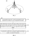
- the communication system 100 may include a network device 110, and the network device 110 may be a device that communicates with a terminal device 120 (or referred to as a communication terminal, or a terminal).
- the network device 110 may provide communication coverage for a specific geographical area, and may communicate with terminal devices located within the coverage area.
- the network device 110 may be a Base Transceiver Station (BTS) in a GSM system or CDMA system, a NodeB (NB) in a WCDMA system, an Evolutional Node B (eNB or eNodeB) in a LTE system, or a radio controller in a Cloud Radio Access Network (CRAN), or the network device may be a network side device in a mobile switch center, a relay station, an access point, a vehicle-mounted device, a wearable device, a hub, a switch, a bridge, a router, or a 5G network, or a network device in a future evolved Public Land Mobile Network (PLMN), etc.
- BTS Base Transceiver Station
- NB NodeB
- eNB or eNodeB Evolutional Node B
- CRAN Cloud Radio Access Network
- PLMN Public Land Mobile Network
- the communication system 100 also includes at least one terminal device 120 located within the coverage area of the network device 110.
- terminal device includes, but not limited to, a device configured to connect via a wired circuit, for example, via a Public Switched Telephone Network (PSTN), a Digital Subscriber Line (DSL), a digital cable, a direct cable; and/or another data connection/network; and/or via a wireless interface, for instance, for a cellular network, a Wireless Local Area Network (WLAN), a digital television network such as a Digital Video Broadcasting-Handheld (DVB-H) network, a satellite network, and an AM-FM broadcast transmitter; and/or an apparatus, of another communication terminal, configured to receive/send a communication signal; and/or an Internet of Things (IoT) device.
- PSTN Public Switched Telephone Network
- DSL Digital Subscriber Line
- WLAN Wireless Local Area Network
- DVD-H Digital Video Broadcasting-Handheld
- satellite network and/or an AM-FM broadcast transmitter
- AM-FM
- a terminal device configured to communicate via a wireless interface may be referred to as a "wireless communication terminal", a “wireless terminal” or a “mobile terminal”.
- the mobile terminal include, but not limited to, a satellite or cellular telephone, a Personal Communication System (PCS) terminal capable of combining with a cellular wireless telephone and data processing, faxing, and data communication abilities, a Personal Digital Assistant (PDA) that may include a radio telephone, a pager, an internet/intranet access, a Web browser, a memo pad, a calendar, and/or a Global Positioning System (GPS) receiver, and a conventional laptop and/or palmtop receiver or another electronic apparatus including a radio telephone transceiver.
- PCS Personal Communication System
- GPS Global Positioning System
- the terminal device may be referred to as an access terminal, a User Equipment (UE), a subscriber unit, a subscriber station, a mobile station, a mobile platform, a remote station, a remote terminal, a mobile device, a user terminal, a terminal, a wireless communication device, a user agent or a user apparatus.
- UE User Equipment
- the access terminal may be a cellular phone, a cordless phone, a Session Initiation Protocol (SIP) phone, a Wireless Local Loop (WLL) station, a Personal Digital Assistant (PDA), a handheld device with a wireless communication function, a computing device, or another processing device connected to a wireless modem, a vehicle-mounted device, a wearable device, a terminal device in a 5G network, or a terminal device in a future evolved Public Land Mobile Network (PLMN), or the like.
- SIP Session Initiation Protocol
- WLL Wireless Local Loop
- PDA Personal Digital Assistant
- PLMN Public Land Mobile Network
- terminal direct connection (Device to Device, D2D) communication may be performed between the terminal devices 120.
- the 5G system or 5G network may be referred to as a New Radio (NR) system or a NR network.
- NR New Radio
- FIG. 1 exemplifies one network device and two terminal devices.
- the communication system 100 may include multiple network devices, and another quantity of terminal devices may be included within a coverage range of each network device, which is not limited by embodiment of the present application.
- the communication system 100 may include other network entities such as a network controller, and a mobile management entity.
- network entities such as a network controller, and a mobile management entity.
- Embodiments of the present application are not limited thereto.
- a device with a communication function in a network/system in the embodiment of the present application may be referred to as a communication device.
- the communication device may include a network device 110 and a terminal device 120 which have communication functions, and the network device 110 and the terminal device 120 may be the specific devices described above, which will not be repeated here.
- the communication device may also include another device in the communication system 100, e.g., another network entity such as a network controller, a mobile management entity, etc., which is not limited by the embodiment of the present application.
- system and “network” are often used interchangeably in this document.
- the term “and/or” in this document is merely an association relationship describing associated objects, indicating that there may be three relationships, for example, A and/or B may indicate three cases: A alone, A and B, and B alone.
- the symbol “/” in this document generally indicates that objects before and after the symbol "/" have an "or” relationship.
- FIGs. 2 to 3 show main acts or operations of the method for reporting a signal of the embodiment of the present application, but these acts or operations are only examples, and the embodiment of the present application may also perform other operations or variations of various operations of FIGs. 2 to 3 .
- various acts in the method embodiment of the present application may also be performed in a different order as described in the method embodiment, and it is possible that not all operations in the method embodiment need to be performed.
- FIG. 2 is a schematic flow chart of a method for reporting a signal according to an embodiment of the present application. As shown in FIG. 2 , the method 200 includes following contents.
- a terminal device determines a signal to be measured for signal measurement according to resource configuration information; in S220, the terminal device measures a first report quantity of the signal to be measured to obtain a measurement result for the first report quantity of the signal to be measured, wherein the first report quantity includes other report quantities except a Layer1-Reference Signal Receiving Power (L1-RSRP); and in S230, the terminal device determines a signal required to be reported in the signal to be measured according to the measurement result for the first report quantity of the signal to be measured.
- L1-RSRP Layer1-Reference Signal Receiving Power
- the signal to be measured may include a Channel State Information Reference Signal (CSI-RS), or may also include all or part of signals in a Synchronization Signal Block (SSB), for example, it may include only a Secondary Synchronization Signal (SSS), or may also include an SSS and a Physical Broadcast Channel (PBCH), or include an SSS and a Demodulation Reference Signal (DMRS), etc., or may also include another downlink reference signal, which is not specifically limited in the embodiment of the present application.
- CSI-RS Channel State Information Reference Signal
- SSB Synchronization Signal Block
- PBCH Physical Broadcast Channel
- DMRS Demodulation Reference Signal
- the first report quantity may include other report quantities except a Layer1-Reference Signal Receiving Power (L1-RSRP), for example, a Layer1-Signal to Interference plus Noise Ratio (L1-SINR), or a Layer1-Reference Signal Receiving Quality (L1-RSRQ), or it may also include other information used for characterizing a signal quality, for example, a Layer1-Received Signal Strength Indication (L1-RSSI), etc., and the embodiment of the present application are not limited to this.
- L1-RSRP Layer1-Reference Signal Receiving Power
- L1-SINR Layer1-Signal to Interference plus Noise Ratio
- L1-RSRQ Layer1-Reference Signal Receiving Quality
- L1-RSSI Layer1-Received Signal Strength Indication
- the network device may configure a physical layer reporting setting for the terminal device, wherein a reporting amount indicated in the reporting setting is the first reporting amount, and the reporting setting is associated with at least one resource setting which is used for configuring a signal to be measured for signal measurement, so that, the terminal device may measure a first report quantity of the signal to be measured indicated by the at least one resource setting to obtain a measurement result for the first report quantity of the signal to be measured, and may further determine a signal required to be reported in the signal to be measured according to the measurement result for the first report quantity of the signal to be measured, for example, K signals with a best signal quality, wherein K is a positive integer.
- a terminal device may measure other report quantities except an L1-RSRP, and make signal selection according to a measurement result for other report quantities, realizing flexibility of signal measurement and improving system performance.
- the selection of signal made according to the measurement results for the L1-RSRP may bring a larger error, so the selection of signal made according to measurement results for other report quantities except the L1-RSRP, such as the L1-SINR or the L1-RSRQ, is beneficial to selecting a signal with a better quality and more reliability, which thus can improve system performance.
- the S220 may include: the terminal device measures the signal to be measured to acquire information of a useful signal; the terminal device acquires corresponding information of interference and noise or total energy; the terminal device determines a measurement result for L1-SINR or L1-RSRQ of the signal to be measured according to the information of the useful signal and the information of interference and noise or the total energy.
- the information of interference and noise may be obtained by measuring the signal to be measured, or obtained by measuring a specific resource location or a specific signal, and similarly, the total energy may also be obtained by measuring the signal to be measured, or obtained by measuring a specific resource location or a specific signal, which is not limited by the embodiment of the present application. That is, the signal used for determining the information of the useful signal and the signal used for determining the information of interference and noise or the total energy may be a same signal or different signals.
- the total energy may include signals and noises of a serving cell and a same frequency cell and the like.
- the terminal device may determine the measurement result for L1-SINR of the signal to be measured according to the information of the useful signal and combining the information of interference and noise, or determine the measurement result for L1-RSRQ of the signal to be measured according to the information of the useful signal and combining the total energy.
- the information of the useful signal may be a strength, a power or an energy of the useful signal, etc.
- the information of the useful signal may be understood as the L1-RSRP, wherein the L1-RSRP may be an average value of signal powers received on all Resource Elements (REs) carrying a reference signal within a certain symbol.
- the L1-SINR may refer to a ratio of the strength of the received useful signal to the strength of the received interference signal (including noise and interference).
- the L1-RSRQ represents a reference signal receiving quality and may be defined as N*L1-RSRP/L1-RSSI, wherein N is a quantity of Resource Blocks (RBs) of a measurement bandwidth of the L1-RSSI.
- the L1-RSSI is a total received power or a total energy on all REs of one symbol within one measurement bandwidth, that is, the total energy may be the L1-RSSI.
- measuring the L1-SINR requires measuring the information of the useful signal and the information of interference and noise
- measuring the L1-RSRQ requires measuring the information and the total energy of the useful signal
- the first report quantity includes an L1-SINR or an L1-RSRQ
- the resource configuration information only includes first resource configuration information, that is, the reporting setting is associated with only one resource setting, wherein the first resource configuration information indicates N first signals.
- the signal to be measured includes the N first signals
- the terminal device may measure each of the N first signals to determine a measurement result for the first report quantity corresponding to each signal, that is, each first signal corresponds to one measurement result. Take one of the N first signals as an example to explain the signal measurement process.
- S11 is performed, in which the terminal device may measure the first signal indicated by the first resource configuration information to acquire the information of the useful signal corresponding to the first signal; further, if the first report quantity is the L1-SINR, S12 is performed, in which the information of interference and noise corresponding to the first signal is acquired on a Resource Element (RE) carrying the first signal; or if the first report quantity is the L1-RSRQ, S12' is performed, in which the total energy corresponding to the first signal is acquired based on part or all of symbols carrying the first signal.
- RE Resource Element
- the measurement result for L1-SINR corresponding to the first signal is determined according to the information of the useful signal corresponding to the first signal and the information of interference and noise corresponding to the first signal.
- the measurement result for L1-SINR corresponding to the first signal may be obtained by dividing the strength of the useful signal and the strength of interference and noise.
- the measurement result for L1-RSRQ of the first signal is determined according to the information of the useful signal corresponding to the first signal and the total energy corresponding to the first signal, for example, the measurement result for L1-SINR corresponding to the first signal may be obtained according to a formula N*L1-RSRP/L1-RSSI.
- the process described in S11 ⁇ S13 is performed on each of the N first signals, that is, the measurement result for L1-SINR or L1-RSRQ corresponding to each first signal may be obtained. Therefore, the terminal device may determine K signals with a best signal quality for reporting according to the measurement results for L1-SINR or L1-RSRQ corresponding to the N first signals, for example, report the measurement results for L1-SINR or L1-RSRQ of the K signals and identification information of the K signals to the network device.
- the measurement result for L1-SINR may be a measurement value of L1-SINR itself, or a difference between measurement values of L1-SINR (for example, a difference relative to a specific measurement value, or a difference between measurement values, etc.), or a quantized value of a measurement value of L1-SINR, etc.
- the embodiment of the present application does not limit the reporting form of the measurement result for L1-SINR.
- For the measurement result for L1-RSRQ it is similar and will not be repeated here.
- the identification information of the K signals may be a CSI-RS resource index and/or an SSB index.
- the K signals are CSI-RS, and the identification information of the K signals may be a CSI-RS resource index; or if the K signals are SSB signals, the identification information of the K signals may be the SSB index.
- a bandwidth used to acquire the information of the useful signal corresponding to the first signal is the same as RE and a bandwidth used to acquire the information of interference and noise corresponding to the first signal. That is, the bandwidths and RE used for performing S11 and S12 are the same.
- the measurement result for L1-SINR or L1-RSRQ corresponding to each first signal may be obtained only through needing to sequentially perform S11 ⁇ S13.
- the measurement result for L1-SINR or L1-RSRQ corresponding to the first signal may be determined in following two modes. Taking determining the measurement result for L1-SINR corresponding to the first signal as an example, the measurement result for L1-RSRQ of the first signal may be determined in a similar mode, which is not repeated.
- mode 1 for each port, the above S11 to S13 are sequentially performed to determine the measurement result for L1-SINR of each port, and then the measurement result for L1-SINR corresponding to the first signal is determined according to the measurement result for L1-SINR corresponding to each port.
- the specific process is as follows: firstly, the information of the useful signal corresponding to each port and the information of interference and noise corresponding to each port are determined; then, the measurement result for L1-SINR corresponding to each port is determined according to the information of the useful signal corresponding to each port and the information of interference and noise or total energy corresponding to each port.
- the measurement result for L1-SINR corresponding to the first signal is determined according to the measurement result for L1-SINR corresponding to each port.
- the measurement result for L1-SINR corresponding to the first signal may be obtained by linearly superimposing the measurement result for L1-SINR corresponding to the each port, or an average value, a maximum value or a minimum value of the measurement result for L1-SINR corresponding to each port may be determined as the measurement result for L1-SINR corresponding to the first signal.
- S11 to S13 are sequentially performed to determine the measurement result for L1-SINR of each port, and then the average value, the maximum value or the minimum value of the measurement result for L1-SINR corresponding to each port may be determined as the measurement result for L1-SINR corresponding to the first signal.
- the information of the useful signal corresponding to the first signal is determined according to the information of the useful signal corresponding to each port in the multiple ports, and the information of interference and noise corresponding to the first signal is determined according to the information of interference and noise corresponding to the each port, then the measurement result for L1-SINR corresponding to the first signal is determined according to the information of the useful signal corresponding to the first signal and the information of interference and noise corresponding to the first signal.
- the average value, the maximum value or the minimum value of the information of the useful signal of each port in the multiple ports may be determined as the information of the useful signal corresponding to the first signal.
- the average value, the maximum value or the minimum value of the information of interference and noise of each port in the multiple ports may be determined as the information of interference and noise corresponding to the first signal.
- the measurement result for L1-SINR corresponding to the first signal is determined according to the information of the useful signal corresponding to the first signal and the information of interference and noise corresponding to the first signal.
- the first report quantity includes L1-SINR or L1-RSRQ
- the resource configuration information includes first resource configuration information and second resource configuration information
- the first resource configuration information is used for indicating N first signals
- the signal to be measured includes the N first signals
- the N is a positive integer
- the second resource configuration information is used for configuring a resource location or a second signal for interference and noise measurement or total energy measurement.
- S21 is performed first, in which the terminal device may measure the first signal indicated by the first resource configuration information to acquire the information of the corresponding useful signal.
- the specific process is similar to S11 in embodiment 1, and will not be repeated; further, if the first report quantity is L1-SINR, S22 is performed, in which the information of interference and noise corresponding to the first signal is acquired according to the resource location or the second signal indicated by the second resource configuration information; or if the first report quantity is L1-RSRQ, S22' is performed, in which the corresponding total energy is acquired according to the resource location or the second signal indicated by the second resource configuration information.
- the measurement result for L1-SINR corresponding to the first signal is determined according to the information of the useful signal corresponding to the first signal and the corresponding information of interference and noise.
- the measurement result for L1-SINR corresponding to the first signal may be obtained by dividing the strength of the useful signal and the strength of interference and noise.
- the measurement result for L1-RSRQ of the first signal is determined according to the information of the useful signal corresponding to the first signal and the corresponding total energy, for example, the measurement result for L1-SINR corresponding to the first signal may be obtained according to a formula N*L1-RSRP/L1-RSSI.
- the process described in S21-S23 is performed on each of the N first signals, that is, the measurement result for L1-SINR or L1-RSRQ corresponding to each first signal may be obtained. Therefore, K signals with a best signal quality may be determined for reporting according to the measurement results for L1-SINR or L1-RSRQ corresponding to the N first signals, for example, the measurement results for L1-SINR or L1-RSRQ of the K signals and identification information of the K signals are reported to the network device.
- the resource location for interference and noise measurement indicated by the second resource configuration information includes a symbol location and/or a subcarrier location, that is, the second resource configuration information may configure a time domain location, a frequency domain location and a signal and the like, for interference and noise measurement, or for total energy measurement.
- the bandwidth used to acquire the information of the useful signal corresponding to the first signal is the same as the RE and the bandwidth used to acquire the corresponding information of interference and noise. That is, the bandwidth and the RE used for performing S21 and S22 are same.
- the measurement result for L1-SINR or L1-RSRQ corresponding to each first signal may be obtained only by sequentially performing S21-S23.
- the second signal used for interference and noise or total energy measurement may be one port or multiple ports, and the ports of the first signal and the second signal may have a one-to-one correspondence or a multiple-to-one correspondence, which is not limited by the embodiments of the present application. It is assumed that the first signal has multiple first sending ports and the second signal has at least one second sending port.
- the terminal device may first calculate the measurement result for L1-SINR or L1-RSRQ of each port separately, and then determine the measurement result for L1-SINR or L1-RSRQ corresponding to the first signal according to the measurement result for L1-SINR or L1-RSRQ of each port. Or in S21 and S22 or S22', the information of the measured signals of multiple ports may also be directly used, and determining the measurement result for L1-SINR corresponding to the first signal is taken as an example for explanation.
- the measurement result for L1-SINR of each port is determined, and then the measurement result for L1-SINR corresponding to the first signal is determined according to the measurement result for L1-SINR corresponding to each port.
- the specific process is as follows: the information of the useful signal of each first sending port and the corresponding information of interference and noise of the second sending port are determined; then the measurement result for L1-SINR of each first sending port is determined according to the information of the useful signal of the each first sending port and the corresponding information of interference and noise or total energy of the second sending port.
- the measurement result for L1-SINR corresponding to the first signal is determined according to the measurement result for L1-SINR of each first sending port.
- the measurement result for L1-SINR of each first sending port may be linearly superimposed to obtain the measurement result for L1-SINR corresponding to the first signal, or an average value, a maximum value or a minimum value of the measurement result for L1-SINR of the each first sending port may be determined as the measurement result for L1-SINR corresponding to the first signal.
- the information of the useful signal of the first signal is determined according to the information of the useful signal of each first sending port in the multiple first sending ports, and the information of interference and noise corresponding to the first signal is determined according to the information of interference and noise of the each second sending port, and then the measurement result for L1-SINR corresponding to the first signal is determined according to the information of the useful signal of the first signal and corresponding information of interference and noise.
- the average value, the maximum value or the minimum value of the information of the useful signal of each first sending port in the multiple first sending ports may be determined as the information of the useful signal of the first signal.
- an average value, a maximum value or a minimum value of the information of interference and noise of each second sending port in the at least one second sending port may be determined as the corresponding information of interference and noise; further, in S23, the measurement result for L1-SINR corresponding to the first signal is determined according to the information of the useful signal of the first signal and the corresponding information of interference and noise.
- the signal to be measured may only include CSI-RS, or SSB, or both signals in CSI-RS and SSB.
- the signals in the CSI-RS and the SSB may have a one-to-one correspondence, satisfying a Quasi-co-located (QCL) relationship; or, the CSI-RS and the SSB may not satisfy the QCL relationship.
- the CSI-RS and the SSB may come from different beams, because comparing L1-SINR with L1-RSRP, L1-SINRs of different reference signals may be directly compared to determine pros and cons of a signal quality.
- the method 200 further includes: the terminal device reports the signal required to be reported to the network device according to one of following modes: periodic, aperiodic, semi-persistent feedback on Physical Uplink Shared Channel (PUSCH) (semiPersistentOnPUSCH), semi-persistent feedback on Physical Uplink Control Channel (PUCCH) (semiPersistentOnPUCCH).
- PUSCH Physical Uplink Shared Channel
- PUCCH Physical Uplink Control Channel
- the method 200 further includes: the terminal device receives first configuration information of the network device, wherein the first configuration information is used for configuring whether the terminal device supports signal reporting based on a beam group (i.e., groupBasedBeamReporting).
- a beam group i.e., groupBasedBeamReporting
- the method 200 further includes: the terminal device receives second configuration information of the network device, wherein the second configuration information is used for configuring a quantity K of reported signals (i.e., nrofReportedRS) .
- the second configuration information is used for configuring a quantity K of reported signals (i.e., nrofReportedRS) .
- the method 200 further includes: the terminal device receives third configuration information of the network device, wherein the third configuration information is used for configuring the terminal device for broadband reporting or sub-band reporting.
- the method for reporting a signal according to the embodiment of the present application is described in detail from the perspective of a terminal device above in combination with FIG. 2
- a method for reporting a signal according to another embodiment of the present application is described in detail from the perspective of a network device below in combination with FIG. 3 .
- the description of the network device side corresponds to the description of the terminal device side, and the above description may be referred to for similar descriptions, which will not be repeated here to avoid repetition.
- FIG. 3 is a schematic flowchart of a method 300 for reporting a signal according to another embodiment of the present application, and the method 300 may be performed by the network device in the communication system shown in FIG. 1 . As shown in FIG. 3 , the method 300 includes a following content.
- the network device sends resource configuration information to the terminal device, wherein the resource configuration information is used for the terminal device to determine a signal to be measured for signal measuring to measure a first report quantity of the signal to be measured, and obtain a measurement result for the first report quantity of the signal to be measured, wherein the first report quantity includes other report quantities except a Layer 1-Reference Signal Receiving Power (L1-RSRP); the network device receives a report result sent by the terminal device, wherein the report result includes information of a signal determined by the terminal device in the signal to be measured according to the measurement result for the first report quantity of the signal to be measured.
- L1-RSRP Layer 1-Reference Signal Receiving Power
- the other report quantity except the Layer 1-Reference Signal Receiving Power is Layer 1-Signal to Interference plus Noise Ratio (L1-SINR) or Layer 1-Reference Signal Receiving Quality (L1-RSRQ).
- the first report quantity further includes information related to a reference signal resource identification.
- the information related to the reference signal resource identification includes index information of a Channel State Information Reference Signal (CSI-RS) resource and/or index information of a Synchronization Signal Block (SSB).
- CSI-RS Channel State Information Reference Signal
- SSB Synchronization Signal Block
- the resource configuration information only includes first resource configuration information, wherein the first resource configuration information is used for channel measurement of L1-RSRP, L1-SINR or L1-RSRQ.
- the resource configuration information includes first resource configuration information and second resource configuration information, wherein a signal indicated by the first resource configuration information is used for channel measurement to determine information of a useful signal, and the second resource configuration information is used for configuring a resource location or a signal for interference and noise measurement or total energy measurement.
- the resource configuration information may also include more pieces of resource configuration information, such as three or more, wherein first resource configuration information in the resource configuration information is used for measuring information of a useful signal, and other resource configuration information except the first resource configuration information is used for interference and noise measurement, or total energy measurement, etc.
- the terminal device may perform interference and noise measurement or total energy measurement according to the second resource configuration information and the third resource configuration information.
- the signal to be measured is part or all of signals in a Channel State Information Reference Signal (CSI-RS) and/or a Synchronization Signal Block (SSB).
- CSI-RS Channel State Information Reference Signal
- SSB Synchronization Signal Block
- the signals in CSI-RS and SSB correspond to each other one by one, satisfying a Quasi-co-located (QCL) relationship.
- QCL Quasi-co-located
- the CSI-RS and the SSB do not satisfy the QCL relationship.
- the method 300 further includes: the network device sends first configuration information to the terminal device, wherein the first configuration information is used for configuring whether the terminal device supports signal reporting based on a beam group.
- the method 300 further includes: the network device sends second configuration information to the terminal device, wherein the second configuration information is used for configuring a quantity of reported signals.
- the method 300 further includes: the network device sends third configuration information to the terminal device, wherein the third configuration information is used for configuring the terminal device to perform broadband reporting or sub-band reporting.
- FIG. 4 shows a schematic block diagram of a terminal device 400 according to an embodiment of the present application.
- the terminal device 400 includes a communicating module 610 and a determining module 620.
- the determining module 410 is configured to determine a signal to be measured for signal measurement according to resource configuration information; the measuring module 420 is configured to measure a first report quantity of the signal to be measured to obtain a measurement result for the first report quantity of the signal to be measured, wherein the first report quantity includes other report quantities except a Layer 1-Reference Signal Receiving Power (L1-RSRP); and the determining module 410 is further configured to determine a signal required to be reported in the signal to be measured according to the measurement result for the first report quantity of the signal to be measured.
- L1-RSRP Layer 1-Reference Signal Receiving Power
- the other report quantity except the Layer1-Reference Signal Receiving Power is Layer 1-Signal to Interference plus Noise Ratio (L1-SINR) or Layer 1-Reference Signal Receiving Quality (L1-RSRQ).
- the first report quantity also includes information related to a reference signal resource identification.
- the information related to the reference signal resource identification includes index information of a Channel State Information Reference Signal (CSI-RS) resource and/or index information of a Synchronization Signal Block (SSB).
- CSI-RS Channel State Information Reference Signal
- SSB Synchronization Signal Block
- the measuring module 420 is specifically configured to measure the signal to be measured and acquire information of a useful signal; acquire corresponding information of interference and noise or total energy; the determining module 410 is further configured to determine a measurement result for L1-SINR or L1-RSRQ of the signal to be measured according to the information of the useful signal and the information of interference and noise or the total energy.
- the resource configuration information only includes first resource configuration information, wherein the first resource configuration information is used for indicating N first signals, and the signal to be measured includes the N first signals, wherein N is a positive integer, and the measuring module 420 is further configured to measure the first signal indicated by the first resource configuration information to acquire information of a useful signal corresponding to the first signal.
- the measuring module 420 is further configured to: acquire information of interference and noise corresponding to the first signal on a Resource Element (RE) carrying the first signal, if the first report quantity includes L1-SINR; or acquire a total energy corresponding to the first signal based on part or all of symbols carrying the first signal, if the first report quantity includes L1-RSRQ.
- RE Resource Element
- the determining module 410 is specifically configured to: determine a measurement result for L1-SINR corresponding to the first signal according to the information of the useful signal corresponding to the first signal and the information of interference and noise corresponding to the first signal; or determine a measurement result for L1-RSRQ corresponding to the first signal according to the information of the useful signal corresponding to the first signal and the total energy corresponding to the first signal.
- the determining module 410 is specifically configured to determine information of a useful signal corresponding to each port in multiple ports and information of interference and noise corresponding to the each port; determine the measurement result for L1-SINR or L1-RSRQ corresponding to the each port according to the information of the useful signal corresponding to the each port and the information of interference and noise or total energy corresponding to the each port; and determine an average value, a maximum value or a minimum value of the measurement result for L1-SINR or L1-RSRQ corresponding to the each port as the measurement result for L1-SINR or L1-RSRQ corresponding to the first signal.
- the determining module 410 is specifically configured to determine information of the useful signal corresponding to each port in multiple ports, and determine an average value, a maximum value or a minimum value in the information of the useful signal corresponding to each port in the multiple ports as the information of the useful signal corresponding to the first signal; determine information of interference and noise or total energy corresponding to the each port, and determine an average value, a maximum value or a minimum value in the information of interference and noise or the total energy corresponding to the each port in the multiple ports as the information or the total energy of interference and noise corresponding to the first signal; determine the measurement result for L1-SINR or L1-RSRQ corresponding to the first signal according to the information of the useful signal corresponding to the first signal and the information of interference and noise or the total energy corresponding to the first signal.
- a bandwidth used to acquire the information of the useful signal corresponding to the first signal is the same as RE and a bandwidth used to acquire the information of interference and noise corresponding to the first signal.
- the total energy corresponding to the first signal includes an energy of signal and noise of a serving cell and a same frequency cell.
- the one piece of resource configuration information is used for channel measurement of L1-RSRP, L1-SINR or L1-RSRQ.
- the resource configuration information includes first resource configuration information and second resource configuration information
- the first resource configuration information is used for indicating N first signals
- the signal to be measured includes the N first signals
- the N is a positive integer
- the second resource configuration information is used for configuring a resource location or a second signal for interference and noise measurement or total energy measurement.
- the measuring module 420 is further configured to measure the first signal indicated by the first resource configuration information to acquire the information of the useful signal corresponding to the first signal.
- the measuring module 420 is further configured to: acquire the corresponding information of interference and noise according to the resource location or the second signal indicated by the second resource configuration information, if the first report quantity contains L1-SINR; or acquire the corresponding total energy according to the resource location or the second signal indicated by the second resource configuration information, if the first report quantity contains L1-RSRQ.
- a bandwidth used to acquire the useful signal corresponding to the first signal is the same as RE and a bandwidth used to acquire the information of interference and noise.
- the total energy includes an energy of signal and noise of a serving cell and a same frequency cell.
- the determining module 410 is further configured to: determine a measurement result for L1-SINR corresponding to the first signal according to the information of the useful signal corresponding to the first signal and the information of interference and noise; or determine a measurement result for L1-RSRQ corresponding to the first signal according to the information of the useful signal corresponding to the first signal and the total energy.
- the resource location for interference and noise measurement includes a symbol location and/or a subcarrier location for interference and noise measurement.
- the resource configuration information further includes third resource configuration information, wherein the third resource configuration information is used for configuring a resource location or a third signal for interference and noise measurement.
- the sending port of the first signal is multiple first sending ports
- the sending port of the second signal is at least one second sending port
- the determining module 410 is specifically configured to: determine information of a useful signal corresponding to each of the multiple first sending ports and information of interference and noise or a total energy corresponding to each second sending port; determine a measurement result for L1-SINR or L1-RSRQ of the each first sending port according to the information of the useful signal of each first sending port and the corresponding information of interference and noise or total energy of the second sending port; determine an average value, a maximum value or a minimum value of the measurement result for L1-SINR or L1-RSRQ corresponding to each first sending port as the measurement result for L1-SINR or L1-RSRQ corresponding to the first signal.
- the sending port of the first signal is multiple first sending ports
- the sending port of the second signal is at least one second sending port
- the determining module 410 is specifically configured to: determine information of a useful signal of each of the multiple first sending ports, and determine an average value, a maximum value or a minimum value in the information of the useful signal of each of the multiple first sending ports as the information of the useful signal corresponding to the first signal; determine information of interference and noise or a total energy of the each second sending port, and determine an average value, a maximum value or a minimum value in the information of interference and noise or the total energy of each second sending port in the at least one second sending port as the corresponding information of interference and noise or total energy; determine the measurement result for L1-SINR or L1-RSRQ corresponding to the first signal according to the information of the useful signal corresponding to the first signal and the corresponding information of interference and noise or total energy.
- the signals in CSI-RS and SSB correspond to each other one by one, satisfying a Quasi-co-located (QCL) relationship.
- QCL Quasi-co-located
- the signal to be measured includes signals in CSI-RS and SSB
- the CSI-RS and the SSB do not satisfy the QCL relationship.
- the terminal device further includes: a communicating module, configured to report the signal required to be reported to the network device according to one of following modes: periodically or aperiodically, feeding back semi-continuously on a Physical Uplink Shared Channel (PUSCH), and feeding back semi-continuously on a Physical Uplink Control Channel (PUCCH).
- a communicating module configured to report the signal required to be reported to the network device according to one of following modes: periodically or aperiodically, feeding back semi-continuously on a Physical Uplink Shared Channel (PUSCH), and feeding back semi-continuously on a Physical Uplink Control Channel (PUCCH).
- PUSCH Physical Uplink Shared Channel
- PUCCH Physical Uplink Control Channel
- the terminal device further includes a communicating module, configured to receive first configuration information of the network device, wherein the first configuration information is used for configuring whether the terminal device supports signal reporting based on a beam group.
- the terminal device further includes a communicating module, configured to receive second configuration information of the network device, wherein the second configuration information is used for configuring a quantity of reported signals.
- the terminal device further includes a communicating module, configured to receive third configuration information of the network device, wherein the third configuration information is used for configuring the terminal device to perform broadband reporting or subband reporting.
- the terminal device 400 may correspond to (e.g., may be configured in or be itself) the terminal device described in the method 200, and various modules or units in the terminal device 400 are respectively used for executing various actions or processes performed by the network device in the method 200.
- various modules or units in the terminal device 400 are respectively used for executing various actions or processes performed by the network device in the method 200.
- detailed description thereof is omitted.
- FIG. 5 is a schematic block diagram of a network device according to an embodiment of the present application.
- a network device 500 in FIG. 5 includes a determining module 510 and a communicating module 520.
- the communicating module 510 is configured to send resource configuration information to a terminal device, wherein the resource configuration information is used for the terminal device to determine a signal to be measured for signal measuring to measure a first report quantity of the signal to be measured, and obtain a measurement result for the first report quantity of the signal to be measured, wherein the first report quantity includes other report quantities except a Layer 1-Reference Signal Receiving Power (L1-RSRP); as well as receive a report result sent by the terminal device, wherein the report result includes information of a signal determined by the terminal device in the signal to be measured according to the measurement result for the first report quantity of the signal to be measured.
- L1-RSRP Layer 1-Reference Signal Receiving Power
- the other report quantity except the Layer 1-Reference Signal Receiving Power is Layer 1-Signal to Interference plus Noise Ratio (L1-SINR) or Layer 1-Reference Signal Receiving Quality (L1-RSRQ).
- the first report quantity further includes information related to a reference signal resource identification.
- the information related to the reference signal resource identification includes index information of a Channel State Information Reference Signal (CSI-RS) resource and/or index information of a Synchronization Signal Block (SSB).
- CSI-RS Channel State Information Reference Signal
- SSB Synchronization Signal Block
- the resource configuration information only includes first resource configuration information, wherein the first resource configuration information is used for channel measurement of L1-RSRP, L1-SINR or L1-RSRQ.
- the resource configuration information includes first resource configuration information and second resource configuration information, wherein a signal indicated by the first resource configuration information is used for channel measurement to determine information of a useful signal, and the second resource configuration information is used for configuring a resource location or a signal for interference and noise measurement or total energy measurement.
- the resource configuration information further includes third resource configuration information, wherein the third resource configuration information is used for configuring the resource location or the signal for interference and noise measurement or total energy measurement.
- the signal to be measured is part or all of signals in a Channel State Information Reference Signal (CSI-RS) and/or a Synchronization Signal Block (SSB).
- CSI-RS Channel State Information Reference Signal
- SSB Synchronization Signal Block
- the signals in CSI-RS and SSB correspond to each other one by one, satisfying a Quasi-co-located (QCL) relationship.
- QCL Quasi-co-located
- the CSI-RS and the SSB do not satisfy the QCL relationship.
- the communicating module 510 is further configured to send first configuration information to the terminal device, wherein the first configuration information is used for configuring whether the terminal device supports signal reporting based on a beam group.
- the communicating module 510 is further configured to send second configuration information to the terminal device, wherein the second configuration information is used for configuring a quantity of reported signals.
- the communicating module 510 is further configured to send third configuration information to the terminal device, wherein the third configuration information is used for configuring the terminal device to perform broadband reporting or sub-band reporting.
- the network device 500 may correspond to (e.g., may be configured in or be itself) the network device described in the method 300, and various modules or units in the network device 500 are respectively used for executing various actions or processes performed by the network device in the method 300.
- various modules or units in the network device 500 are respectively used for executing various actions or processes performed by the network device in the method 300.
- detailed description thereof is omitted.
- FIG. 6 is a schematic structural diagram of a communication device 600 according to an embodiment of the present application.
- the communication device 600 shown in FIG. 6 includes a processor 610.
- the processor 610 may call and run a computer program from a memory to implement the method in the embodiment of the present application.
- the communication device 600 may further include a memory 620.
- the processor 610 may call and run a computer program from the memory 620 to implement the method in the embodiment of the present application.
- the memory 620 may be a separate device independent of the processor 610 or may be integrated in the processor 610.
- the communication device 600 may further include a transceiver 630, and the processor 610 may control the transceiver 630 to communicate with another device. Specifically, information or data may be sent to another device, or information or data sent by another device is received.
- the transceiver 630 may include a transmitter and a receiver.
- the transceiver 630 may further include antennas, and the quantity of antennas may be one or more.
- the communication device 600 may specifically be a network device of the embodiment of the present application, and the communication device 600 may implement corresponding processes implemented by the network device in various methods of the embodiments of the present application, which will not be repeated here for brevity.
- the communication device 600 may be specifically a mobile terminal/terminal device of the embodiment of the present application, and the communication device 600 may implement corresponding processes implemented by the mobile terminal/terminal device in various methods of the embodiment of the present application, which will not be repeated here for brevity.
- FIG. 7 is a schematic diagram of a structure of a chip of an embodiment of the present application.
- a chip 700 shown in FIG. 7 includes a processor 710.
- the processor 710 may call and run a computer program from a memory to implement the method in the embodiment of the present application.
- the chip 700 may further include a memory 720.
- the processor 710 may call and run a computer program from the memory 720 to implement the method in the embodiment of the present application.
- the memory 720 may be a separate device independent of the processor 710 or may be integrated in the processor 710.
- the chip 700 may further include an input interface 730.
- the processor 710 may control the input interface 730 to communicate with other devices or chips. Specifically, the processor 710 may acquire information or data sent by other devices or chips.
- the chip 700 may further include an output interface 740.
- the processor 710 may control the output interface 740 to communicate with other devices or chips. Specifically, the processor 710 may output information or data to other devices or chips.
- the chip may be applied in a network device of the embodiment of the present application, and the chip may implement the corresponding processes implemented by the network device in various methods of the embodiment of the present application, which will not be repeated here for brevity.
- the chip may be applied in a mobile terminal/terminal device of the embodiment of the present application, and the chip may implement the corresponding processes implemented by the mobile terminal/terminal device in the various methods of the embodiment of the present application, which will not be repeated here for brevity.
- the chip mentioned in the embodiment of the present application may be referred to as a system-level chip, a system chip, a chip system or a system-on-chip, etc.
- FIG. 8 is a schematic block diagram of a communication system 900 according to an embodiment of the present application.
- the communication system 900 may include a terminal device 910 and a network device 920.
- the terminal device 910 may be configured to implement the corresponding functions implemented by the terminal device in the above-mentioned method
- the network device 920 may be configured to implement the corresponding functions implemented by the network device in the above-mentioned method, which will not be repeated here for brevity.
- the processor in the embodiment of the present application may be an integrated circuit chip having a signal processing capability.
- the acts of the foregoing method embodiments may be implemented by using an integrated logic circuit of hardware in the processor or instructions in a form of software.
- the processor may be a general purpose processor, a digital signal processor (Digital Signal Processing, DSP), an application specific integrated circuit (Application Specific Integrated Circuit, ASIC), a field programmable gate array (Field Programmable Gate Array, FPGA) or another programmable logic device, a discrete gate or a transistor logic device, or a discrete hardware component.
- DSP Digital Signal Processing
- ASIC Application Specific Integrated Circuit
- FPGA Field Programmable Gate Array
- the processor may implement or perform methods, acts and logical block diagrams disclosed in the embodiment of the present application.
- the general purpose processor may be a microprocessor, or the processor may be any conventional processor or the like.
- the acts of the method disclosed with reference to the embodiment of the present application may be directly implemented by a hardware decoding processor, or may be implemented by a combination of hardware and software modules in the decoding processor.
- the software modules may be located in a storage medium commonly used in the art, such as a random access memory, a flash memory, a read-only memory, a programmable read-only memory or an electrically erasable programmable memory, or a register.
- the storage medium is located in the memory, and the processor reads the information in the memory and completes the acts of the above method in combination with its hardware.
- the memory in the embodiment of the present application may be a transitory memory or a non-transitory memory, or may include both a transitory memory and a non-transitory memory.
- the non-transitory memory may be a read-only memory (Read-Only Memory, ROM), a programmable read-only memory (Programmable ROM, PROM), an erasable programmable read-only memory (Erasable PROM, EPROM), an electrically erasable programmable read-only memory (Electrically EPROM, EEPROM), or a flash memory.
- the transitory memory may be a random access memory (Random Access Memory, RAM), and is used as an external cache.
- RAMs may be used, for example, a static random access memory (Static RAM, SRAM), a dynamic random access memory (Dynamic RAM, DRAM), a synchronous dynamic random access memory (Synchronous DRAM, SDRAM), a double data rate synchronous dynamic random access memory (Double Data Rate SDRAM, DDR SDRAM), an enhanced synchronous dynamic random access memory (Enhanced SDRAM, ESDRAM), a synchronous link dynamic random access memory (Synchlink DRAM, SLDRAM), and a direct rambus dynamic random access memory (Direct Rambus RAM, DR RAM).
- Static RAM static random access memory
- DRAM dynamic random access memory
- DRAM synchronous dynamic random access memory
- SDRAM double data rate synchronous dynamic random access memory
- Enhanced SDRAM, ESDRAM enhanced synchronous dynamic random access memory
- Synchlink DRAM synchronous link dynamic random access memory
- DR RAM direct rambus dynamic random access memory
- the memory in the embodiments of the present application may be a Static RAM (SRAM), a Dynamic RAM (DRAM), a Synchronous DRAM (SDRAM), a Double Data Rate SDRAM (DDR SDRAM), an Enhanced SDRAM (ESDRAM), a Synchlink DRAM (SLDRAM), a Direct Rambus RAM (DR RAM), or the like. That is, memories in the embodiments of the present application are intended to include, but are not limited to, these and any other suitable types of memories.
- SRAM Static RAM
- DRAM Dynamic RAM
- SDRAM Synchronous DRAM
- DDR SDRAM Double Data Rate SDRAM
- ESDRAM Enhanced SDRAM
- SLDRAM Synchlink DRAM
- DR RAM Direct Rambus RAM
- An embodiment of the present application further provides a computer readable storage medium configured to store a computer program.
- the computer readable storage medium may be applied in a network device of the embodiment of the present application, and the computer program causes a computer to perform corresponding processes implemented by the network device in various methods of the embodiments of the present application, which will not be repeated here for brevity.
- the computer readable storage medium may be applied in a mobile terminal/terminal device of the embodiment of the present application, and the computer program causes a computer to perform corresponding processes implemented by the mobile terminal/terminal device in various methods of the embodiments of the present application, which will not be repeated here for brevity.
- An embodiment of the present application also provides a computer program product including computer program instructions.
- the computer program product may be applied in a network device of the embodiment of the present application, and the computer program instructions cause a computer to perform corresponding processes implemented by the network device in various methods of the embodiments of the present application, which will not be repeated here for brevity.
- the computer program product may be applied in a mobile terminal/terminal device of the embodiment of the present application, and the computer program instructions cause a computer to perform corresponding processes implemented by the mobile terminal/terminal device in various methods according to the embodiment of the present application, which will not be repeated here for brevity.
- An embodiment of the present application also provides a computer program.
- the computer program may be applied in a network device of the embodiment of the present application.
- the computer program When the computer program is run on a computer, the computer is caused to perform corresponding processes implemented by the network device in various methods of the embodiments of the present application, which will not be repeated here for brevity.
- the computer program may be applied in a mobile terminal/terminal device of the embodiment of the present application.
- the computer program When the computer program is run on a computer, the computer is caused to perform corresponding processes implemented by the mobile terminal/terminal device in various methods of the embodiment of the present application, which will not be repeated here for brevity.
- the disclosed systems, apparatuses and methods may be implemented in other modes.
- the apparatus embodiments described above are only illustrative, for example, the division of the units is only a logical function division, and there may be other division manners in actual implementation, for example, multiple units or components may be combined or integrated into another system, or some features may be ignored or not executed.
- the mutual coupling or direct coupling or communication connection shown or discussed may be indirect coupling or communication connection through some interface, apparatus or unit, and may be in electrical, mechanical or other forms.
- the unit described as a separate component may or may not be physically separated, and the component shown as a unit may or may not be a physical unit, i.e., it may be located in one place or may be distributed over multiple network units. Some or all of the units may be selected according to actual needs to achieve the purpose of the embodiments.
- various functional units in various embodiments of the present application may be integrated in one processing unit, or the various units may be physically present separately, or two or more units may be integrated in one unit.
- the functions may be stored in a computer readable storage medium if realized in a form of software functional units and sold or used as a separate product.
- the technical solution of the present application in essence, or the part contributing to the prior art, or the part of the technical solution, may be embodied in the form of a software product stored in a storage medium, including a number of instructions for causing a computer device (which may be a personal computer, a server, or a network device and the like) to perform all or part of the acts of the method described in various embodiments of the present application.
- the foregoing storage medium includes: any medium that may store program code, such as a USB flash drive, a removable hard disk, a read-only memory (Read-Only Memory, ROM), a random access memory (Random Access Memory, RAM), a magnetic disk, or an optical disc.
- program code such as a USB flash drive, a removable hard disk, a read-only memory (Read-Only Memory, ROM), a random access memory (Random Access Memory, RAM), a magnetic disk, or an optical disc.
Landscapes
- Engineering & Computer Science (AREA)
- Signal Processing (AREA)
- Computer Networks & Wireless Communication (AREA)
- Quality & Reliability (AREA)
- Physics & Mathematics (AREA)
- Electromagnetism (AREA)
- Mobile Radio Communication Systems (AREA)
Abstract
Description
- Embodiments of the present application relate to the field of communication, specifically to a method for reporting a signal, a terminal device and a network device.
- In a 5G multi-beam system, a terminal device may measure a Layer1-Reference Signal Receiving Power (L1-RSRP) of multiple signals, and determine which beams have a better transmission quality based on a measurement result, or beams transmitting these signals have a better transmission quality, so that the terminal device may report information of these signals, such as beam information or the measurement result, to a network device.
- However, the measurement mode based on the L1-RSRP is too simple, and in some cases, a quality of a determined signal is not necessarily optimal. In this case, how to measure a signal to determine a reported signal is an urgent problem to be solved.
- Embodiments of the present application provide a method for reporting a signal, a terminal device and a network device, which can achieve a measurement on a report quantity except an L1-RSRP to determine a reported signal.
- In a first aspect, a method for reporting a signal is provided, including: determining, by a terminal device, a signal to be measured for signal measurement according to resource configuration information; measuring, by the terminal device, a first report quantity of the signal to be measured to obtain a measurement result for the first report quantity of the signal to be measured, wherein the first report quantity includes other report quantities except a Layer1-Reference Signal Receiving Power (L1-RSRP); and determining, by the terminal device, a signal required to be reported in the signal to be measured according to the measurement result for the first report quantity of the signal to be measured.
- In a second aspect, a method for reporting a signal is provided, including: sending, by a network device, resource configuration information to a terminal device, wherein the resource configuration information is used for the terminal device to determine a signal to be measured for signal measurement, so as to measure a first report quantity of the signal to be measured and obtain a measurement result for the first report quantity of the signal to be measured, wherein the first report quantity includes other report quantities except a Layer1-Reference Signal Receiving Power (L1-RSRP); receiving, by the network device, a report result sent by the terminal device, wherein the report result includes information of a signal determined by the terminal device in the signal to be measured according to the measurement result for the first report quantity of the signal to be measured.
- In a third aspect, a terminal device is provided, which is used for performing the method in the above first aspect or any possible implementation of the first aspect. Specifically, the terminal device includes units for performing the method of the first aspect or the method in any possible implementation of the first aspect.
- In a fourth aspect, a network device is provided, which is used for performing the method in the above second aspect or any possible implementation of the second aspect. Specifically, the terminal device includes units for performing the method in the above second aspect or any possible implementation of the second aspect.
- In a fifth aspect, a terminal device is provided, including a processor and a memory. The memory is configured to store a computer program, and the processor is configured to call and run the computer program stored in the memory to execute the method in the above first aspect or each implementation thereof.
- In a sixth aspect, a network device is provided, including a processor and a memory. The memory is used for storing a computer program, and the processor is used for calling and running the computer program stored in the memory to execute the method in the above second aspect or each implementation thereof.
- In a seventh aspect, a chip is provided, configured to implement the method in any one of the above first to second aspects or each implementation thereof.
- Specifically, the chip includes a processor, configured to call and run a computer program from a memory, so that a device with which the chip is disposed performs the method in any one of the above first to second aspects or each implementation thereof.
- In an eighth aspect, a computer readable storage medium is provided, configured to store a computer program, wherein the computer program causes a computer to perform the method in any one of the above first to second aspects or each implementation thereof.
- In a ninth aspect, a computer program product is provided, including computer program instructions, wherein the computer program instructions cause a computer to perform the method in any one of the above first to second aspects or each implementation thereof.
- In a tenth aspect, a computer program is provided, which, when being run on a computer, causes the computer to perform the method in any one of the above first to second aspects or each implementation thereof.
- Based on the above technical solution, a network device may configure a terminal device with a first report quantity, wherein the first report quantity is other report quantities except an L1-RSRP, so that the terminal device may measure the first report quantity of a signal to be measured, and make signal selection according to a measurement result for the first report quantity, which is beneficial to improving flexibility of signal measurement, and make signal selection based on a measurement result for another report quantity except the L1-RSRP, which is, in some cases, beneficial to selecting a signal with a better quality and more reliable, which thus can improve system performance.
-
-
FIG. 1 is a schematic diagram of architecture of a communication system according to an embodiment of the present application. -
FIG. 2 is a schematic flow chart of a method for reporting a signal according to an embodiment of the present application. -
FIG. 3 is a schematic diagram of a method for reporting a signal according to another embodiment of the present application. -
FIG. 4 is a schematic block diagram of a terminal device according to an embodiment of the present application. -
FIG. 5 is a schematic block diagram of a network device according to an embodiment of the present application. -
FIG. 6 is a schematic block diagram of a communication device according to an embodiment of the present application. -
FIG. 7 is a schematic block diagram of a chip according to an embodiment of the present application. -
FIG. 8 is a schematic block diagram of a communication system according to an embodiment of the present application. - The technical solution in embodiments of the present application will be described below with reference to the drawings in embodiments of the present application. It is apparent that the embodiments described are just some embodiments of the present application, but not all embodiments of the present application. According to the embodiments of the present application, all other embodiments achieved by a person of ordinary skill in the art without paying an inventive effort are within the protection scope of the present application.
- The technical solutions of the embodiments of the present application may be applied to various communication systems, such as a Global System of Mobile communication (GSM) system, a Code Division Multiple Access (CDMA) system, a Wideband Code Division Multiple Access (WCDMA) system, a General Packet Radio Service (GPRS), a Long Term Evolution (LTE) system, a LTE Frequency Division Duplex (FDD) system, a LTE Time Division Duplex (TDD) system, a Universal Mobile Telecommunication System (UMTS), a Worldwide Interoperability for Microwave Access (WiMAX) communication system, or a 5G system.
- Illustratively, a
communication system 100 applied in an embodiment of the present application is shown inFIG. 1 . Thecommunication system 100 may include anetwork device 110, and thenetwork device 110 may be a device that communicates with a terminal device 120 (or referred to as a communication terminal, or a terminal). Thenetwork device 110 may provide communication coverage for a specific geographical area, and may communicate with terminal devices located within the coverage area. Optionally, thenetwork device 110 may be a Base Transceiver Station (BTS) in a GSM system or CDMA system, a NodeB (NB) in a WCDMA system, an Evolutional Node B (eNB or eNodeB) in a LTE system, or a radio controller in a Cloud Radio Access Network (CRAN), or the network device may be a network side device in a mobile switch center, a relay station, an access point, a vehicle-mounted device, a wearable device, a hub, a switch, a bridge, a router, or a 5G network, or a network device in a future evolved Public Land Mobile Network (PLMN), etc. - The
communication system 100 also includes at least oneterminal device 120 located within the coverage area of thenetwork device 110. As used herein, the term "terminal device" includes, but not limited to, a device configured to connect via a wired circuit, for example, via a Public Switched Telephone Network (PSTN), a Digital Subscriber Line (DSL), a digital cable, a direct cable; and/or another data connection/network; and/or via a wireless interface, for instance, for a cellular network, a Wireless Local Area Network (WLAN), a digital television network such as a Digital Video Broadcasting-Handheld (DVB-H) network, a satellite network, and an AM-FM broadcast transmitter; and/or an apparatus, of another communication terminal, configured to receive/send a communication signal; and/or an Internet of Things (IoT) device. A terminal device configured to communicate via a wireless interface may be referred to as a "wireless communication terminal", a "wireless terminal" or a "mobile terminal". Examples of the mobile terminal include, but not limited to, a satellite or cellular telephone, a Personal Communication System (PCS) terminal capable of combining with a cellular wireless telephone and data processing, faxing, and data communication abilities, a Personal Digital Assistant (PDA) that may include a radio telephone, a pager, an internet/intranet access, a Web browser, a memo pad, a calendar, and/or a Global Positioning System (GPS) receiver, and a conventional laptop and/or palmtop receiver or another electronic apparatus including a radio telephone transceiver. The terminal device may be referred to as an access terminal, a User Equipment (UE), a subscriber unit, a subscriber station, a mobile station, a mobile platform, a remote station, a remote terminal, a mobile device, a user terminal, a terminal, a wireless communication device, a user agent or a user apparatus. The access terminal may be a cellular phone, a cordless phone, a Session Initiation Protocol (SIP) phone, a Wireless Local Loop (WLL) station, a Personal Digital Assistant (PDA), a handheld device with a wireless communication function, a computing device, or another processing device connected to a wireless modem, a vehicle-mounted device, a wearable device, a terminal device in a 5G network, or a terminal device in a future evolved Public Land Mobile Network (PLMN), or the like. - Optionally, terminal direct connection (Device to Device, D2D) communication may be performed between the
terminal devices 120. - Optionally, the 5G system or 5G network may be referred to as a New Radio (NR) system or a NR network.
-
FIG. 1 exemplifies one network device and two terminal devices. Optionally, thecommunication system 100 may include multiple network devices, and another quantity of terminal devices may be included within a coverage range of each network device, which is not limited by embodiment of the present application. - Optionally, the
communication system 100 may include other network entities such as a network controller, and a mobile management entity. Embodiments of the present application are not limited thereto. - It should be understood that, a device with a communication function in a network/system in the embodiment of the present application may be referred to as a communication device. Taking the
communication system 100 shown inFIG. 1 as an example, the communication device may include anetwork device 110 and aterminal device 120 which have communication functions, and thenetwork device 110 and theterminal device 120 may be the specific devices described above, which will not be repeated here. The communication device may also include another device in thecommunication system 100, e.g., another network entity such as a network controller, a mobile management entity, etc., which is not limited by the embodiment of the present application. - It should be understood that the terms "system" and "network" are often used interchangeably in this document. The term "and/or" in this document is merely an association relationship describing associated objects, indicating that there may be three relationships, for example, A and/or B may indicate three cases: A alone, A and B, and B alone. In addition, the symbol "/" in this document generally indicates that objects before and after the symbol "/" have an "or" relationship.
- Hereinafter, a method for reporting a signal according to an embodiment of the present application will be described with reference to
FIGs. 2 to 3 . It should be understood thatFIGs. 2 to 3 show main acts or operations of the method for reporting a signal of the embodiment of the present application, but these acts or operations are only examples, and the embodiment of the present application may also perform other operations or variations of various operations ofFIGs. 2 to 3 . In addition, various acts in the method embodiment of the present application may also be performed in a different order as described in the method embodiment, and it is possible that not all operations in the method embodiment need to be performed. -
FIG. 2 is a schematic flow chart of a method for reporting a signal according to an embodiment of the present application. As shown inFIG. 2 , themethod 200 includes following contents. - In S210, a terminal device determines a signal to be measured for signal measurement according to resource configuration information; in S220, the terminal device measures a first report quantity of the signal to be measured to obtain a measurement result for the first report quantity of the signal to be measured, wherein the first report quantity includes other report quantities except a Layer1-Reference Signal Receiving Power (L1-RSRP); and in S230, the terminal device determines a signal required to be reported in the signal to be measured according to the measurement result for the first report quantity of the signal to be measured.
- Optionally, in the embodiment of the present application, the signal to be measured may include a Channel State Information Reference Signal (CSI-RS), or may also include all or part of signals in a Synchronization Signal Block (SSB), for example, it may include only a Secondary Synchronization Signal (SSS), or may also include an SSS and a Physical Broadcast Channel (PBCH), or include an SSS and a Demodulation Reference Signal (DMRS), etc., or may also include another downlink reference signal, which is not specifically limited in the embodiment of the present application.
- Optionally, in the embodiment of the present application, the first report quantity may include other report quantities except a Layer1-Reference Signal Receiving Power (L1-RSRP), for example, a Layer1-Signal to Interference plus Noise Ratio (L1-SINR), or a Layer1-Reference Signal Receiving Quality (L1-RSRQ), or it may also include other information used for characterizing a signal quality, for example, a Layer1-Received Signal Strength Indication (L1-RSSI), etc., and the embodiment of the present application are not limited to this.
- Specifically, the network device may configure a physical layer reporting setting for the terminal device, wherein a reporting amount indicated in the reporting setting is the first reporting amount, and the reporting setting is associated with at least one resource setting which is used for configuring a signal to be measured for signal measurement, so that, the terminal device may measure a first report quantity of the signal to be measured indicated by the at least one resource setting to obtain a measurement result for the first report quantity of the signal to be measured, and may further determine a signal required to be reported in the signal to be measured according to the measurement result for the first report quantity of the signal to be measured, for example, K signals with a best signal quality, wherein K is a positive integer.
- Therefore, in the method for reporting a signal of the embodiment of the present application, a terminal device may measure other report quantities except an L1-RSRP, and make signal selection according to a measurement result for other report quantities, realizing flexibility of signal measurement and improving system performance.
- In some scenarios, if measurement results for the L1-RSRP of the signal to be measured are not much different, or signal qualities of the signal to be measured are determined to be similar based on the measurement results for the L1-RSRP, in this case, the selection of signal made according to the measurement results for the L1-RSRP may bring a larger error, so the selection of signal made according to measurement results for other report quantities except the L1-RSRP, such as the L1-SINR or the L1-RSRQ, is beneficial to selecting a signal with a better quality and more reliability, which thus can improve system performance.
- Optionally, as an embodiment, if the first report quantity includes an L1-SINR or an L1-RSRQ, the S220 may include: the terminal device measures the signal to be measured to acquire information of a useful signal; the terminal device acquires corresponding information of interference and noise or total energy; the terminal device determines a measurement result for L1-SINR or L1-RSRQ of the signal to be measured according to the information of the useful signal and the information of interference and noise or the total energy.
- It should be understood that the information of interference and noise may be obtained by measuring the signal to be measured, or obtained by measuring a specific resource location or a specific signal, and similarly, the total energy may also be obtained by measuring the signal to be measured, or obtained by measuring a specific resource location or a specific signal, which is not limited by the embodiment of the present application. That is, the signal used for determining the information of the useful signal and the signal used for determining the information of interference and noise or the total energy may be a same signal or different signals. Here, the total energy may include signals and noises of a serving cell and a same frequency cell and the like.
- Further, the terminal device may determine the measurement result for L1-SINR of the signal to be measured according to the information of the useful signal and combining the information of interference and noise, or determine the measurement result for L1-RSRQ of the signal to be measured according to the information of the useful signal and combining the total energy.
- It should be understood that the information of the useful signal may be a strength, a power or an energy of the useful signal, etc. In some specific embodiments, the information of the useful signal may be understood as the L1-RSRP, wherein the L1-RSRP may be an average value of signal powers received on all Resource Elements (REs) carrying a reference signal within a certain symbol. The L1-SINR may refer to a ratio of the strength of the received useful signal to the strength of the received interference signal (including noise and interference). The L1-RSRQ represents a reference signal receiving quality and may be defined as N*L1-RSRP/L1-RSSI, wherein N is a quantity of Resource Blocks (RBs) of a measurement bandwidth of the L1-RSSI. The L1-RSSI is a total received power or a total energy on all REs of one symbol within one measurement bandwidth, that is, the total energy may be the L1-RSSI.
- It can be seen from this, measuring the L1-SINR requires measuring the information of the useful signal and the information of interference and noise, and measuring the L1-RSRQ requires measuring the information and the total energy of the useful signal.
- The measurement method of the L1-SINR and the L1-RSRQ will be described in detail with reference to embodiment 1 and embodiment 2 below.
- Embodiment 1: the first report quantity includes an L1-SINR or an L1-RSRQ, and the resource configuration information only includes first resource configuration information, that is, the reporting setting is associated with only one resource setting, wherein the first resource configuration information indicates N first signals. In the embodiment 1, the signal to be measured includes the N first signals, and the terminal device may measure each of the N first signals to determine a measurement result for the first report quantity corresponding to each signal, that is, each first signal corresponds to one measurement result. Take one of the N first signals as an example to explain the signal measurement process.
- At first, S11 is performed, in which the terminal device may measure the first signal indicated by the first resource configuration information to acquire the information of the useful signal corresponding to the first signal; further, if the first report quantity is the L1-SINR, S12 is performed, in which the information of interference and noise corresponding to the first signal is acquired on a Resource Element (RE) carrying the first signal; or if the first report quantity is the L1-RSRQ, S12' is performed, in which the total energy corresponding to the first signal is acquired based on part or all of symbols carrying the first signal.
- At last, S13 is performed, in which the measurement result for L1-SINR corresponding to the first signal is determined according to the information of the useful signal corresponding to the first signal and the information of interference and noise corresponding to the first signal. For example, the measurement result for L1-SINR corresponding to the first signal may be obtained by dividing the strength of the useful signal and the strength of interference and noise.
- Or, the measurement result for L1-RSRQ of the first signal is determined according to the information of the useful signal corresponding to the first signal and the total energy corresponding to the first signal, for example, the measurement result for L1-SINR corresponding to the first signal may be obtained according to a formula N*L1-RSRP/L1-RSSI.
- The process described in S11∼S13 is performed on each of the N first signals, that is, the measurement result for L1-SINR or L1-RSRQ corresponding to each first signal may be obtained. Therefore, the terminal device may determine K signals with a best signal quality for reporting according to the measurement results for L1-SINR or L1-RSRQ corresponding to the N first signals, for example, report the measurement results for L1-SINR or L1-RSRQ of the K signals and identification information of the K signals to the network device.
- It should be understood that here, the measurement result for L1-SINR may be a measurement value of L1-SINR itself, or a difference between measurement values of L1-SINR (for example, a difference relative to a specific measurement value, or a difference between measurement values, etc.), or a quantized value of a measurement value of L1-SINR, etc. The embodiment of the present application does not limit the reporting form of the measurement result for L1-SINR. For the measurement result for L1-RSRQ, it is similar and will not be repeated here.
- It should also be understood that the identification information of the K signals may be a CSI-RS resource index and/or an SSB index. For example, if the K signals are CSI-RS, and the identification information of the K signals may be a CSI-RS resource index; or if the K signals are SSB signals, the identification information of the K signals may be the SSB index.
- In the embodiment of the present application, a bandwidth used to acquire the information of the useful signal corresponding to the first signal is the same as RE and a bandwidth used to acquire the information of interference and noise corresponding to the first signal. That is, the bandwidths and RE used for performing S11 and S12 are the same.
- Optionally, in some embodiments, there may be one sending port of the first signal. In this case, the measurement result for L1-SINR or L1-RSRQ corresponding to each first signal may be obtained only through needing to sequentially perform S11∼S13.
- Optionally, in some other embodiments, there may be multiple sending ports of the first signal. In this case, the measurement result for L1-SINR or L1-RSRQ corresponding to the first signal may be determined in following two modes. Taking determining the measurement result for L1-SINR corresponding to the first signal as an example, the measurement result for L1-RSRQ of the first signal may be determined in a similar mode, which is not repeated.
- In mode 1: for each port, the above S11 to S13 are sequentially performed to determine the measurement result for L1-SINR of each port, and then the measurement result for L1-SINR corresponding to the first signal is determined according to the measurement result for L1-SINR corresponding to each port.
- The specific process is as follows: firstly, the information of the useful signal corresponding to each port and the information of interference and noise corresponding to each port are determined; then, the measurement result for L1-SINR corresponding to each port is determined according to the information of the useful signal corresponding to each port and the information of interference and noise or total energy corresponding to each port.
- At last, the measurement result for L1-SINR corresponding to the first signal is determined according to the measurement result for L1-SINR corresponding to each port. For example, the measurement result for L1-SINR corresponding to the first signal may be obtained by linearly superimposing the measurement result for L1-SINR corresponding to the each port, or an average value, a maximum value or a minimum value of the measurement result for L1-SINR corresponding to each port may be determined as the measurement result for L1-SINR corresponding to the first signal.
- That is, for each port, S11 to S13 are sequentially performed to determine the measurement result for L1-SINR of each port, and then the average value, the maximum value or the minimum value of the measurement result for L1-SINR corresponding to each port may be determined as the measurement result for L1-SINR corresponding to the first signal.
- In mode 2: the information of the useful signal corresponding to the first signal is determined according to the information of the useful signal corresponding to each port in the multiple ports, and the information of interference and noise corresponding to the first signal is determined according to the information of interference and noise corresponding to the each port, then the measurement result for L1-SINR corresponding to the first signal is determined according to the information of the useful signal corresponding to the first signal and the information of interference and noise corresponding to the first signal.
- Specifically, in S11, the average value, the maximum value or the minimum value of the information of the useful signal of each port in the multiple ports may be determined as the information of the useful signal corresponding to the first signal.
- In S12, the average value, the maximum value or the minimum value of the information of interference and noise of each port in the multiple ports may be determined as the information of interference and noise corresponding to the first signal.
- Further, in S13, the measurement result for L1-SINR corresponding to the first signal is determined according to the information of the useful signal corresponding to the first signal and the information of interference and noise corresponding to the first signal.
- Embodiment 2: the first report quantity includes L1-SINR or L1-RSRQ, the resource configuration information includes first resource configuration information and second resource configuration information, the first resource configuration information is used for indicating N first signals, the signal to be measured includes the N first signals, the N is a positive integer, and the second resource configuration information is used for configuring a resource location or a second signal for interference and noise measurement or total energy measurement. Take measuring one of the N first signals as an example to explain the signal measurement process.
- In the embodiment 2, S21 is performed first, in which the terminal device may measure the first signal indicated by the first resource configuration information to acquire the information of the corresponding useful signal. The specific process is similar to S11 in embodiment 1, and will not be repeated; further, if the first report quantity is L1-SINR, S22 is performed, in which the information of interference and noise corresponding to the first signal is acquired according to the resource location or the second signal indicated by the second resource configuration information; or if the first report quantity is L1-RSRQ, S22' is performed, in which the corresponding total energy is acquired according to the resource location or the second signal indicated by the second resource configuration information.
- At last, S23 is performed, in which the measurement result for L1-SINR corresponding to the first signal is determined according to the information of the useful signal corresponding to the first signal and the corresponding information of interference and noise. For example, the measurement result for L1-SINR corresponding to the first signal may be obtained by dividing the strength of the useful signal and the strength of interference and noise. Or, the measurement result for L1-RSRQ of the first signal is determined according to the information of the useful signal corresponding to the first signal and the corresponding total energy, for example, the measurement result for L1-SINR corresponding to the first signal may be obtained according to a formula N*L1-RSRP/L1-RSSI.
- Further, the process described in S21-S23 is performed on each of the N first signals, that is, the measurement result for L1-SINR or L1-RSRQ corresponding to each first signal may be obtained. Therefore, K signals with a best signal quality may be determined for reporting according to the measurement results for L1-SINR or L1-RSRQ corresponding to the N first signals, for example, the measurement results for L1-SINR or L1-RSRQ of the K signals and identification information of the K signals are reported to the network device.
- It should be understood that here, the reporting form of the measurement results for L1-SINR or L1-RSRQ and the meaning of identification information of the K signals may refer to the relevant description of embodiment 1, and will not be repeated here for brevity.
- Optionally, in some embodiments, the resource location for interference and noise measurement indicated by the second resource configuration information includes a symbol location and/or a subcarrier location, that is, the second resource configuration information may configure a time domain location, a frequency domain location and a signal and the like, for interference and noise measurement, or for total energy measurement.
- Similar to embodiment 1, the bandwidth used to acquire the information of the useful signal corresponding to the first signal is the same as the RE and the bandwidth used to acquire the corresponding information of interference and noise. That is, the bandwidth and the RE used for performing S21 and S22 are same.
- Optionally, in some embodiments, there may be one sending port for the first signal. In this case, the measurement result for L1-SINR or L1-RSRQ corresponding to each first signal may be obtained only by sequentially performing S21-S23.
- Optionally, in some other embodiments, there may be multiple sending ports of the first signal, the second signal used for interference and noise or total energy measurement may be one port or multiple ports, and the ports of the first signal and the second signal may have a one-to-one correspondence or a multiple-to-one correspondence, which is not limited by the embodiments of the present application. It is assumed that the first signal has multiple first sending ports and the second signal has at least one second sending port.
- Similar to embodiment 1, the terminal device may first calculate the measurement result for L1-SINR or L1-RSRQ of each port separately, and then determine the measurement result for L1-SINR or L1-RSRQ corresponding to the first signal according to the measurement result for L1-SINR or L1-RSRQ of each port. Or in S21 and S22 or S22', the information of the measured signals of multiple ports may also be directly used, and determining the measurement result for L1-SINR corresponding to the first signal is taken as an example for explanation.
- For mode 1: the measurement result for L1-SINR of each port is determined, and then the measurement result for L1-SINR corresponding to the first signal is determined according to the measurement result for L1-SINR corresponding to each port.
- The specific process is as follows: the information of the useful signal of each first sending port and the corresponding information of interference and noise of the second sending port are determined; then the measurement result for L1-SINR of each first sending port is determined according to the information of the useful signal of the each first sending port and the corresponding information of interference and noise or total energy of the second sending port.
- Then the measurement result for L1-SINR corresponding to the first signal is determined according to the measurement result for L1-SINR of each first sending port. For example, the measurement result for L1-SINR of each first sending port may be linearly superimposed to obtain the measurement result for L1-SINR corresponding to the first signal, or an average value, a maximum value or a minimum value of the measurement result for L1-SINR of the each first sending port may be determined as the measurement result for L1-SINR corresponding to the first signal.
- In mode 2: the information of the useful signal of the first signal is determined according to the information of the useful signal of each first sending port in the multiple first sending ports, and the information of interference and noise corresponding to the first signal is determined according to the information of interference and noise of the each second sending port, and then the measurement result for L1-SINR corresponding to the first signal is determined according to the information of the useful signal of the first signal and corresponding information of interference and noise.
- Specifically, in S21, the average value, the maximum value or the minimum value of the information of the useful signal of each first sending port in the multiple first sending ports may be determined as the information of the useful signal of the first signal.
- In S22, an average value, a maximum value or a minimum value of the information of interference and noise of each second sending port in the at least one second sending port may be determined as the corresponding information of interference and noise; further, in S23, the measurement result for L1-SINR corresponding to the first signal is determined according to the information of the useful signal of the first signal and the corresponding information of interference and noise.
- Optionally, in some embodiments, the signal to be measured may only include CSI-RS, or SSB, or both signals in CSI-RS and SSB. In this case, the signals in the CSI-RS and the SSB may have a one-to-one correspondence, satisfying a Quasi-co-located (QCL) relationship; or, the CSI-RS and the SSB may not satisfy the QCL relationship. for example, the CSI-RS and the SSB may come from different beams, because comparing L1-SINR with L1-RSRP, L1-SINRs of different reference signals may be directly compared to determine pros and cons of a signal quality.
- Optionally, in some embodiments, the
method 200 further includes: the terminal device reports the signal required to be reported to the network device according to one of following modes: periodic, aperiodic, semi-persistent feedback on Physical Uplink Shared Channel (PUSCH) (semiPersistentOnPUSCH), semi-persistent feedback on Physical Uplink Control Channel (PUCCH) (semiPersistentOnPUCCH). - Optionally, in some embodiments, the
method 200 further includes: the terminal device receives first configuration information of the network device, wherein the first configuration information is used for configuring whether the terminal device supports signal reporting based on a beam group (i.e., groupBasedBeamReporting). - Optionally, in some embodiments, the
method 200 further includes: the terminal device receives second configuration information of the network device, wherein the second configuration information is used for configuring a quantity K of reported signals (i.e., nrofReportedRS) . - Optionally, in some embodiments, the
method 200 further includes: the terminal device receives third configuration information of the network device, wherein the third configuration information is used for configuring the terminal device for broadband reporting or sub-band reporting. - The method for reporting a signal according to the embodiment of the present application is described in detail from the perspective of a terminal device above in combination with
FIG. 2 , and a method for reporting a signal according to another embodiment of the present application is described in detail from the perspective of a network device below in combination withFIG. 3 . It should be understood that the description of the network device side corresponds to the description of the terminal device side, and the above description may be referred to for similar descriptions, which will not be repeated here to avoid repetition. -
FIG. 3 is a schematic flowchart of amethod 300 for reporting a signal according to another embodiment of the present application, and themethod 300 may be performed by the network device in the communication system shown inFIG. 1 . As shown inFIG. 3 , themethod 300 includes a following content. - In S310, the network device sends resource configuration information to the terminal device, wherein the resource configuration information is used for the terminal device to determine a signal to be measured for signal measuring to measure a first report quantity of the signal to be measured, and obtain a measurement result for the first report quantity of the signal to be measured, wherein the first report quantity includes other report quantities except a Layer 1-Reference Signal Receiving Power (L1-RSRP); the network device receives a report result sent by the terminal device, wherein the report result includes information of a signal determined by the terminal device in the signal to be measured according to the measurement result for the first report quantity of the signal to be measured.
- Optionally, in some embodiments, the other report quantity except the Layer 1-Reference Signal Receiving Power (L1-RSRP) is Layer 1-Signal to Interference plus Noise Ratio (L1-SINR) or Layer 1-Reference Signal Receiving Quality (L1-RSRQ).
- Optionally, in some embodiments, the first report quantity further includes information related to a reference signal resource identification.
- Optionally, in some embodiments, the information related to the reference signal resource identification includes index information of a Channel State Information Reference Signal (CSI-RS) resource and/or index information of a Synchronization Signal Block (SSB).
- Optionally, in some embodiments, the resource configuration information only includes first resource configuration information, wherein the first resource configuration information is used for channel measurement of L1-RSRP, L1-SINR or L1-RSRQ.
- Optionally, in some embodiments, the resource configuration information includes first resource configuration information and second resource configuration information, wherein a signal indicated by the first resource configuration information is used for channel measurement to determine information of a useful signal, and the second resource configuration information is used for configuring a resource location or a signal for interference and noise measurement or total energy measurement.
- Optionally, in some embodiments, the resource configuration information may also include more pieces of resource configuration information, such as three or more, wherein first resource configuration information in the resource configuration information is used for measuring information of a useful signal, and other resource configuration information except the first resource configuration information is used for interference and noise measurement, or total energy measurement, etc.
- For example, if the resource configuration information also includes third resource configuration information, wherein the third resource configuration information is used for configuring a resource location or a signal for interference and noise measurement or total energy measurement, then the terminal device may perform interference and noise measurement or total energy measurement according to the second resource configuration information and the third resource configuration information.
- Optionally, in some embodiments, the signal to be measured is part or all of signals in a Channel State Information Reference Signal (CSI-RS) and/or a Synchronization Signal Block (SSB).
- Optionally, in some embodiments, if the signal to be measured includes signals in CSI-RS and SSB, the signals in CSI-RS and SSB correspond to each other one by one, satisfying a Quasi-co-located (QCL) relationship.
- Optionally, in some embodiments, if the signal includes signals in CSI-RS and SSB, the CSI-RS and the SSB do not satisfy the QCL relationship.
- Optionally, in some embodiments, the
method 300 further includes: the network device sends first configuration information to the terminal device, wherein the first configuration information is used for configuring whether the terminal device supports signal reporting based on a beam group. - Optionally, in some embodiments, the
method 300 further includes: the network device sends second configuration information to the terminal device, wherein the second configuration information is used for configuring a quantity of reported signals. - Optionally, in some embodiments, the
method 300 further includes: the network device sends third configuration information to the terminal device, wherein the third configuration information is used for configuring the terminal device to perform broadband reporting or sub-band reporting. - Method embodiments of the present application are described in detail above with reference to
FIGs. 2 to 3 , apparatus embodiments of the present application are described in detail below with reference toFIGs. 4 to 8 . It should be understood that the apparatus embodiments and the method embodiments correspond to each other, and description of the method embodiments may be referred to for similar description of the apparatus embodiments. -
FIG. 4 shows a schematic block diagram of aterminal device 400 according to an embodiment of the present application. As shown inFIG. 4 , theterminal device 400 includes a communicatingmodule 610 and a determiningmodule 620. - The determining
module 410 is configured to determine a signal to be measured for signal measurement according to resource configuration information; themeasuring module 420 is configured to measure a first report quantity of the signal to be measured to obtain a measurement result for the first report quantity of the signal to be measured, wherein the first report quantity includes other report quantities except a Layer 1-Reference Signal Receiving Power (L1-RSRP); and the determiningmodule 410 is further configured to determine a signal required to be reported in the signal to be measured according to the measurement result for the first report quantity of the signal to be measured. - Optionally, in some embodiments, the other report quantity except the Layer1-Reference Signal Receiving Power (L1-RSRP) is Layer 1-Signal to Interference plus Noise Ratio (L1-SINR) or Layer 1-Reference Signal Receiving Quality (L1-RSRQ).
- Optionally, in some embodiments, the first report quantity also includes information related to a reference signal resource identification.
- Optionally, in some embodiments, the information related to the reference signal resource identification includes index information of a Channel State Information Reference Signal (CSI-RS) resource and/or index information of a Synchronization Signal Block (SSB).
- Optionally, in some embodiments, the measuring
module 420 is specifically configured to measure the signal to be measured and acquire information of a useful signal; acquire corresponding information of interference and noise or total energy; the determiningmodule 410 is further configured to determine a measurement result for L1-SINR or L1-RSRQ of the signal to be measured according to the information of the useful signal and the information of interference and noise or the total energy. - Optionally, in some embodiments, the resource configuration information only includes first resource configuration information, wherein the first resource configuration information is used for indicating N first signals, and the signal to be measured includes the N first signals, wherein N is a positive integer, and the
measuring module 420 is further configured to measure the first signal indicated by the first resource configuration information to acquire information of a useful signal corresponding to the first signal. - Optionally, in some embodiments, the measuring
module 420 is further configured to: acquire information of interference and noise corresponding to the first signal on a Resource Element (RE) carrying the first signal, if the first report quantity includes L1-SINR; or acquire a total energy corresponding to the first signal based on part or all of symbols carrying the first signal, if the first report quantity includes L1-RSRQ. - Optionally, in some embodiments, the determining
module 410 is specifically configured to: determine a measurement result for L1-SINR corresponding to the first signal according to the information of the useful signal corresponding to the first signal and the information of interference and noise corresponding to the first signal; or determine a measurement result for L1-RSRQ corresponding to the first signal according to the information of the useful signal corresponding to the first signal and the total energy corresponding to the first signal. - Optionally, in some embodiments, there is one sending port for the first signal.
- Optionally, in some embodiments, there are multiple sending ports for the first signal, and the determining
module 410 is specifically configured to determine information of a useful signal corresponding to each port in multiple ports and information of interference and noise corresponding to the each port; determine the measurement result for L1-SINR or L1-RSRQ corresponding to the each port according to the information of the useful signal corresponding to the each port and the information of interference and noise or total energy corresponding to the each port; and determine an average value, a maximum value or a minimum value of the measurement result for L1-SINR or L1-RSRQ corresponding to the each port as the measurement result for L1-SINR or L1-RSRQ corresponding to the first signal. - Optionally, in some embodiments, there are multiple sending ports for the first signal, and the determining
module 410 is specifically configured to determine information of the useful signal corresponding to each port in multiple ports, and determine an average value, a maximum value or a minimum value in the information of the useful signal corresponding to each port in the multiple ports as the information of the useful signal corresponding to the first signal; determine information of interference and noise or total energy corresponding to the each port, and determine an average value, a maximum value or a minimum value in the information of interference and noise or the total energy corresponding to the each port in the multiple ports as the information or the total energy of interference and noise corresponding to the first signal; determine the measurement result for L1-SINR or L1-RSRQ corresponding to the first signal according to the information of the useful signal corresponding to the first signal and the information of interference and noise or the total energy corresponding to the first signal. - Optionally, in some embodiments, a bandwidth used to acquire the information of the useful signal corresponding to the first signal is the same as RE and a bandwidth used to acquire the information of interference and noise corresponding to the first signal.
- Optionally, in some embodiments, the total energy corresponding to the first signal includes an energy of signal and noise of a serving cell and a same frequency cell.
- Optionally, in some embodiments, if only one piece of resource configuration information is configured on the terminal device, the one piece of resource configuration information is used for channel measurement of L1-RSRP, L1-SINR or L1-RSRQ.
- Optionally, in some embodiments, the resource configuration information includes first resource configuration information and second resource configuration information, the first resource configuration information is used for indicating N first signals, the signal to be measured includes the N first signals, the N is a positive integer, and the second resource configuration information is used for configuring a resource location or a second signal for interference and noise measurement or total energy measurement.
- Optionally, in some embodiments, the measuring
module 420 is further configured to measure the first signal indicated by the first resource configuration information to acquire the information of the useful signal corresponding to the first signal. - Optionally, in some embodiments, the measuring
module 420 is further configured to: acquire the corresponding information of interference and noise according to the resource location or the second signal indicated by the second resource configuration information, if the first report quantity contains L1-SINR; or acquire the corresponding total energy according to the resource location or the second signal indicated by the second resource configuration information, if the first report quantity contains L1-RSRQ. - Optionally, in some embodiments, a bandwidth used to acquire the useful signal corresponding to the first signal is the same as RE and a bandwidth used to acquire the information of interference and noise.
- Optionally, the total energy includes an energy of signal and noise of a serving cell and a same frequency cell.
- Optionally, in some embodiments, the determining
module 410 is further configured to: determine a measurement result for L1-SINR corresponding to the first signal according to the information of the useful signal corresponding to the first signal and the information of interference and noise; or determine a measurement result for L1-RSRQ corresponding to the first signal according to the information of the useful signal corresponding to the first signal and the total energy. - Optionally, in some embodiments, the resource location for interference and noise measurement includes a symbol location and/or a subcarrier location for interference and noise measurement.
- Optionally, in some embodiments, the resource configuration information further includes third resource configuration information, wherein the third resource configuration information is used for configuring a resource location or a third signal for interference and noise measurement.
- Optionally, in some embodiments, there is one sending port for the first signal and the second signal.
- Optionally, in some embodiments, the sending port of the first signal is multiple first sending ports, the sending port of the second signal is at least one second sending port, and the determining
module 410 is specifically configured to: determine information of a useful signal corresponding to each of the multiple first sending ports and information of interference and noise or a total energy corresponding to each second sending port; determine a measurement result for L1-SINR or L1-RSRQ of the each first sending port according to the information of the useful signal of each first sending port and the corresponding information of interference and noise or total energy of the second sending port; determine an average value, a maximum value or a minimum value of the measurement result for L1-SINR or L1-RSRQ corresponding to each first sending port as the measurement result for L1-SINR or L1-RSRQ corresponding to the first signal. - Optionally, in some embodiments, the sending port of the first signal is multiple first sending ports, the sending port of the second signal is at least one second sending port, and the determining
module 410 is specifically configured to: determine information of a useful signal of each of the multiple first sending ports, and determine an average value, a maximum value or a minimum value in the information of the useful signal of each of the multiple first sending ports as the information of the useful signal corresponding to the first signal; determine information of interference and noise or a total energy of the each second sending port, and determine an average value, a maximum value or a minimum value in the information of interference and noise or the total energy of each second sending port in the at least one second sending port as the corresponding information of interference and noise or total energy; determine the measurement result for L1-SINR or L1-RSRQ corresponding to the first signal according to the information of the useful signal corresponding to the first signal and the corresponding information of interference and noise or total energy. - Optionally, in some embodiments, if the signal to be measured includes signals in CSI-RS and SSB, the signals in CSI-RS and SSB correspond to each other one by one, satisfying a Quasi-co-located (QCL) relationship.
- Optionally, in some embodiments, if the signal to be measured includes signals in CSI-RS and SSB, the CSI-RS and the SSB do not satisfy the QCL relationship.
- Optionally, in some embodiments, the terminal device further includes: a communicating module, configured to report the signal required to be reported to the network device according to one of following modes: periodically or aperiodically, feeding back semi-continuously on a Physical Uplink Shared Channel (PUSCH), and feeding back semi-continuously on a Physical Uplink Control Channel (PUCCH).
- Optionally, in some embodiments, the terminal device further includes a communicating module, configured to receive first configuration information of the network device, wherein the first configuration information is used for configuring whether the terminal device supports signal reporting based on a beam group.
- Optionally, in some embodiments, the terminal device further includes a communicating module, configured to receive second configuration information of the network device, wherein the second configuration information is used for configuring a quantity of reported signals.
- Optionally, in some embodiments, the terminal device further includes a communicating module, configured to receive third configuration information of the network device, wherein the third configuration information is used for configuring the terminal device to perform broadband reporting or subband reporting.
- Specifically, the
terminal device 400 may correspond to (e.g., may be configured in or be itself) the terminal device described in themethod 200, and various modules or units in theterminal device 400 are respectively used for executing various actions or processes performed by the network device in themethod 200. Herein, in order to avoid redundancy, detailed description thereof is omitted. -
FIG. 5 is a schematic block diagram of a network device according to an embodiment of the present application. Anetwork device 500 inFIG. 5 includes a determiningmodule 510 and a communicating module 520. - The communicating
module 510 is configured to send resource configuration information to a terminal device, wherein the resource configuration information is used for the terminal device to determine a signal to be measured for signal measuring to measure a first report quantity of the signal to be measured, and obtain a measurement result for the first report quantity of the signal to be measured, wherein the first report quantity includes other report quantities except a Layer 1-Reference Signal Receiving Power (L1-RSRP); as well as receive a report result sent by the terminal device, wherein the report result includes information of a signal determined by the terminal device in the signal to be measured according to the measurement result for the first report quantity of the signal to be measured. - Optionally, in some embodiments, the other report quantity except the Layer 1-Reference Signal Receiving Power (L1-RSRP) is Layer 1-Signal to Interference plus Noise Ratio (L1-SINR) or Layer 1-Reference Signal Receiving Quality (L1-RSRQ).
- Optionally, in some embodiments, the first report quantity further includes information related to a reference signal resource identification.
- Optionally, in some embodiments, the information related to the reference signal resource identification includes index information of a Channel State Information Reference Signal (CSI-RS) resource and/or index information of a Synchronization Signal Block (SSB).
- Optionally, in some embodiments, the resource configuration information only includes first resource configuration information, wherein the first resource configuration information is used for channel measurement of L1-RSRP, L1-SINR or L1-RSRQ.
- Optionally, in some embodiments, the resource configuration information includes first resource configuration information and second resource configuration information, wherein a signal indicated by the first resource configuration information is used for channel measurement to determine information of a useful signal, and the second resource configuration information is used for configuring a resource location or a signal for interference and noise measurement or total energy measurement.
- Optionally, in some embodiments, the resource configuration information further includes third resource configuration information, wherein the third resource configuration information is used for configuring the resource location or the signal for interference and noise measurement or total energy measurement.
- Optionally, in some embodiments, the signal to be measured is part or all of signals in a Channel State Information Reference Signal (CSI-RS) and/or a Synchronization Signal Block (SSB).
- Optionally, in some embodiments, if the signal to be measured includes signals in CSI-RS and SSB, the signals in CSI-RS and SSB correspond to each other one by one, satisfying a Quasi-co-located (QCL) relationship.
- Optionally, in some embodiments, if the signal includes signals in CSI-RS and SSB, the CSI-RS and the SSB do not satisfy the QCL relationship.
- Optionally, in some embodiments, the communicating
module 510 is further configured to send first configuration information to the terminal device, wherein the first configuration information is used for configuring whether the terminal device supports signal reporting based on a beam group. - Optionally, in some embodiments, the communicating
module 510 is further configured to send second configuration information to the terminal device, wherein the second configuration information is used for configuring a quantity of reported signals. - Optionally, in some embodiments, the communicating
module 510 is further configured to send third configuration information to the terminal device, wherein the third configuration information is used for configuring the terminal device to perform broadband reporting or sub-band reporting. - Specifically, the
network device 500 may correspond to (e.g., may be configured in or be itself) the network device described in themethod 300, and various modules or units in thenetwork device 500 are respectively used for executing various actions or processes performed by the network device in themethod 300. Herein, in order to avoid redundancy, detailed description thereof is omitted. -
FIG. 6 is a schematic structural diagram of acommunication device 600 according to an embodiment of the present application. Thecommunication device 600 shown inFIG. 6 includes aprocessor 610. Theprocessor 610 may call and run a computer program from a memory to implement the method in the embodiment of the present application. - Optionally, as shown in
FIG. 6 , thecommunication device 600 may further include amemory 620. Theprocessor 610 may call and run a computer program from thememory 620 to implement the method in the embodiment of the present application. - The
memory 620 may be a separate device independent of theprocessor 610 or may be integrated in theprocessor 610. - Optionally, as shown in
FIG. 6 , thecommunication device 600 may further include atransceiver 630, and theprocessor 610 may control thetransceiver 630 to communicate with another device. Specifically, information or data may be sent to another device, or information or data sent by another device is received. - The
transceiver 630 may include a transmitter and a receiver. Thetransceiver 630 may further include antennas, and the quantity of antennas may be one or more. - Optionally, the
communication device 600 may specifically be a network device of the embodiment of the present application, and thecommunication device 600 may implement corresponding processes implemented by the network device in various methods of the embodiments of the present application, which will not be repeated here for brevity. - Optionally, the
communication device 600 may be specifically a mobile terminal/terminal device of the embodiment of the present application, and thecommunication device 600 may implement corresponding processes implemented by the mobile terminal/terminal device in various methods of the embodiment of the present application, which will not be repeated here for brevity. -
FIG. 7 is a schematic diagram of a structure of a chip of an embodiment of the present application. Achip 700 shown inFIG. 7 includes aprocessor 710. Theprocessor 710 may call and run a computer program from a memory to implement the method in the embodiment of the present application. - Optionally, as shown in
FIG. 7 , thechip 700 may further include amemory 720. Theprocessor 710 may call and run a computer program from thememory 720 to implement the method in the embodiment of the present application. - The
memory 720 may be a separate device independent of theprocessor 710 or may be integrated in theprocessor 710. - Optionally, the
chip 700 may further include aninput interface 730. Theprocessor 710 may control theinput interface 730 to communicate with other devices or chips. Specifically, theprocessor 710 may acquire information or data sent by other devices or chips. - Optionally, the
chip 700 may further include anoutput interface 740. Theprocessor 710 may control theoutput interface 740 to communicate with other devices or chips. Specifically, theprocessor 710 may output information or data to other devices or chips. - Optionally, the chip may be applied in a network device of the embodiment of the present application, and the chip may implement the corresponding processes implemented by the network device in various methods of the embodiment of the present application, which will not be repeated here for brevity.
- Optionally, the chip may be applied in a mobile terminal/terminal device of the embodiment of the present application, and the chip may implement the corresponding processes implemented by the mobile terminal/terminal device in the various methods of the embodiment of the present application, which will not be repeated here for brevity.
- It should be understood that the chip mentioned in the embodiment of the present application may be referred to as a system-level chip, a system chip, a chip system or a system-on-chip, etc.
-
FIG. 8 is a schematic block diagram of acommunication system 900 according to an embodiment of the present application. As shown inFIG. 8 , thecommunication system 900 may include aterminal device 910 and anetwork device 920. - Herein, the
terminal device 910 may be configured to implement the corresponding functions implemented by the terminal device in the above-mentioned method, and thenetwork device 920 may be configured to implement the corresponding functions implemented by the network device in the above-mentioned method, which will not be repeated here for brevity. - It should be understood that, the processor in the embodiment of the present application may be an integrated circuit chip having a signal processing capability. In an implementation process, the acts of the foregoing method embodiments may be implemented by using an integrated logic circuit of hardware in the processor or instructions in a form of software. The processor may be a general purpose processor, a digital signal processor (Digital Signal Processing, DSP), an application specific integrated circuit (Application Specific Integrated Circuit, ASIC), a field programmable gate array (Field Programmable Gate Array, FPGA) or another programmable logic device, a discrete gate or a transistor logic device, or a discrete hardware component. The processor may implement or perform methods, acts and logical block diagrams disclosed in the embodiment of the present application. The general purpose processor may be a microprocessor, or the processor may be any conventional processor or the like. The acts of the method disclosed with reference to the embodiment of the present application may be directly implemented by a hardware decoding processor, or may be implemented by a combination of hardware and software modules in the decoding processor. The software modules may be located in a storage medium commonly used in the art, such as a random access memory, a flash memory, a read-only memory, a programmable read-only memory or an electrically erasable programmable memory, or a register. The storage medium is located in the memory, and the processor reads the information in the memory and completes the acts of the above method in combination with its hardware.
- It may be understood that, the memory in the embodiment of the present application may be a transitory memory or a non-transitory memory, or may include both a transitory memory and a non-transitory memory. The non-transitory memory may be a read-only memory (Read-Only Memory, ROM), a programmable read-only memory (Programmable ROM, PROM), an erasable programmable read-only memory (Erasable PROM, EPROM), an electrically erasable programmable read-only memory (Electrically EPROM, EEPROM), or a flash memory. The transitory memory may be a random access memory (Random Access Memory, RAM), and is used as an external cache. Through exemplary but not limitative description, many forms of RAMs may be used, for example, a static random access memory (Static RAM, SRAM), a dynamic random access memory (Dynamic RAM, DRAM), a synchronous dynamic random access memory (Synchronous DRAM, SDRAM), a double data rate synchronous dynamic random access memory (Double Data Rate SDRAM, DDR SDRAM), an enhanced synchronous dynamic random access memory (Enhanced SDRAM, ESDRAM), a synchronous link dynamic random access memory (Synchlink DRAM, SLDRAM), and a direct rambus dynamic random access memory (Direct Rambus RAM, DR RAM). It should be noted that the memory in the systems and methods described in this specification is aimed at including but being not limited to these and any memory of another proper type.
- It should be understood that, the foregoing memory is an example for illustration and should not be construed as limiting. For example, optionally, the memory in the embodiments of the present application may be a Static RAM (SRAM), a Dynamic RAM (DRAM), a Synchronous DRAM (SDRAM), a Double Data Rate SDRAM (DDR SDRAM), an Enhanced SDRAM (ESDRAM), a Synchlink DRAM (SLDRAM), a Direct Rambus RAM (DR RAM), or the like. That is, memories in the embodiments of the present application are intended to include, but are not limited to, these and any other suitable types of memories.
- An embodiment of the present application further provides a computer readable storage medium configured to store a computer program.
- Optionally, the computer readable storage medium may be applied in a network device of the embodiment of the present application, and the computer program causes a computer to perform corresponding processes implemented by the network device in various methods of the embodiments of the present application, which will not be repeated here for brevity.
- Optionally, the computer readable storage medium may be applied in a mobile terminal/terminal device of the embodiment of the present application, and the computer program causes a computer to perform corresponding processes implemented by the mobile terminal/terminal device in various methods of the embodiments of the present application, which will not be repeated here for brevity.
- An embodiment of the present application also provides a computer program product including computer program instructions.
- Optionally, the computer program product may be applied in a network device of the embodiment of the present application, and the computer program instructions cause a computer to perform corresponding processes implemented by the network device in various methods of the embodiments of the present application, which will not be repeated here for brevity.
- Optionally, the computer program product may be applied in a mobile terminal/terminal device of the embodiment of the present application, and the computer program instructions cause a computer to perform corresponding processes implemented by the mobile terminal/terminal device in various methods according to the embodiment of the present application, which will not be repeated here for brevity.
- An embodiment of the present application also provides a computer program.
- Optionally, the computer program may be applied in a network device of the embodiment of the present application. When the computer program is run on a computer, the computer is caused to perform corresponding processes implemented by the network device in various methods of the embodiments of the present application, which will not be repeated here for brevity.
- Optionally, the computer program may be applied in a mobile terminal/terminal device of the embodiment of the present application. When the computer program is run on a computer, the computer is caused to perform corresponding processes implemented by the mobile terminal/terminal device in various methods of the embodiment of the present application, which will not be repeated here for brevity.
- Those of ordinary skill in the art will recognize that the exemplary elements and algorithm acts described in combination with the embodiments disclosed herein may be implemented in electronic hardware, or a combination of computer software and electronic hardware. Whether these functions are implemented in hardware or software depends on the specific application and design constraints of the technical solution. Skilled artisans may use different methods to implement the described functions in respect to each particular application, but such implementation should not be considered to be beyond the scope of the present application.
- Those skilled in the art may clearly understand that for convenience and conciseness of description, the specific working processes of the systems, apparatuses and units described above may refer to the corresponding processes in the method embodiments and will not be described here.
- In several embodiments provided by the present application, it should be understood that the disclosed systems, apparatuses and methods may be implemented in other modes. For example, the apparatus embodiments described above are only illustrative, for example, the division of the units is only a logical function division, and there may be other division manners in actual implementation, for example, multiple units or components may be combined or integrated into another system, or some features may be ignored or not executed. On the other hand, the mutual coupling or direct coupling or communication connection shown or discussed may be indirect coupling or communication connection through some interface, apparatus or unit, and may be in electrical, mechanical or other forms.
- The unit described as a separate component may or may not be physically separated, and the component shown as a unit may or may not be a physical unit, i.e., it may be located in one place or may be distributed over multiple network units. Some or all of the units may be selected according to actual needs to achieve the purpose of the embodiments.
- In addition, various functional units in various embodiments of the present application may be integrated in one processing unit, or the various units may be physically present separately, or two or more units may be integrated in one unit.
- The functions may be stored in a computer readable storage medium if realized in a form of software functional units and sold or used as a separate product. Based on this understanding, the technical solution of the present application, in essence, or the part contributing to the prior art, or the part of the technical solution, may be embodied in the form of a software product stored in a storage medium, including a number of instructions for causing a computer device (which may be a personal computer, a server, or a network device and the like) to perform all or part of the acts of the method described in various embodiments of the present application. The foregoing storage medium includes: any medium that may store program code, such as a USB flash drive, a removable hard disk, a read-only memory (Read-Only Memory, ROM), a random access memory (Random Access Memory, RAM), a magnetic disk, or an optical disc.
- What are described above are merely exemplary embodiments of the present application, but the protection scope of the present application is not limited thereto. Any variation or substitution that may be easily conceived by a person skilled in the art within the technical scope disclosed by the present application shall be included within the protection scope of the present application. Therefore, the protection scope of the present application shall be determined by the protection scope of the claims.
Claims (99)
- A method for reporting a signal, comprising:determining, by a terminal device, a signal to be measured for signal measurement according to resource configuration information;measuring, by the terminal device, a first report quantity of the signal to be measured to obtain a measurement result for the first report quantity of the signal to be measured, wherein the first report quantity comprises other report quantities except a Layer 1-Reference Signal Receiving Power (L1-RSRP); anddetermining, by the terminal device, a signal required to be reported in the signal to be measured according to the measurement result for the first report quantity of the signal to be measured.
- The method according to claim 1, wherein the other report quantity except the Layer1-Reference Signal Receiving Power (L1-RSRP) is Layer 1-Signal to Interference plus Noise Ratio (L1-SINR) or Layer 1-Reference Signal Receiving Quality (L1-RSRQ).
- The method according to claim 2, wherein the first report quantity further comprises information related to a reference signal resource identification.
- The method according to claim 3, wherein the information related to the reference signal resource identification comprises index information of a Channel State Information Reference Signal (CSI-RS) resource and/or index information of a Synchronization Signal Block (SSB).
- The method according to any one of claims 1 to 4, wherein measuring, by the terminal device, the first report quantity of the signal to be measured to obtain the measurement result for the first report quantity of the signal to be measured, comprises:measuring, by the terminal device, the signal to be measured to acquire information of a useful signal;acquiring, by the terminal device, corresponding information of interference and noise or a total energy;determining, by the terminal device, a measurement result for L1-SINR or L1-RSRQ of the signal to be measured according to the information of the useful signal and the information of the interference and noise or the total energy.
- The method according to claim 5, wherein the resource configuration information only comprises first resource configuration information, wherein the first resource configuration information is used for indicating N first signals, and the signal to be measured comprises the N first signals, wherein N is a positive integer, and measuring, by the terminal device, the signal to be measured to acquire the information of the useful signal, comprises:
measuring, by the terminal device, the first signal indicated by the first resource configuration information to acquire the information of the useful signal corresponding to the first signal. - The method according to claim 6, wherein acquiring, by the terminal device, the corresponding information of interference and noise or total energy, comprises:acquiring, by the terminal device, information of interference and noise corresponding to the first signal on a Resource Element (RE) carrying the first signal, if the first report quantity comprises L1-SINR; oracquiring, by the terminal device, a total energy corresponding to the first signal based on part or all of symbols carrying the first signal, if the first report quantity comprises L1-RSRQ.
- The method according to claim 7, wherein determining, by the terminal device, the measurement result for L1-SINR or L1-RSRQ of the signal to be measured according to the information of the useful signal and the information of interference and noise or the total energy, comprises:determining, by the terminal device, a measurement result for L1-SINR corresponding to the first signal according to the information of the useful signal corresponding to the first signal and the information of interference and noise corresponding to the first signal; ordetermining, by the terminal device, a measurement result for L1-RSRQ corresponding to the first signal according to the information of the useful signal corresponding to the first signal and the total energy corresponding to the first signal.
- The method according to any one of claims 6 to 8, wherein there is one sending port for the first signal.
- The method according to any one of claims 6 to 8, wherein there are a plurality of sending ports for the first signal, and the measurement result for L1-SINR or L1-RSRQ corresponding to the first signal is determined according to a following mode:determining information of a useful signal corresponding to each port in a plurality of ports and information of interference and noise corresponding to the each port;determining the measurement result for L1-SINR or L1-RSRQ corresponding to the each port according to the information of the useful signal corresponding to the each port and the information of interference and noise or total energy corresponding to the each port; anddetermining an average value, a maximum value or a minimum value of the measurement result for L1-SINR or L1-RSRQ corresponding to the each port as the measurement result for L1-SINR or L1-RSRQ corresponding to the first signal.
- The method according to any one of claims 6 to 8, wherein there are a plurality of sending ports for the first signal, and the measurement result for L1-SINR corresponding to the first signal is determined according to a following mode:determining information of a useful signal corresponding to each port in a plurality of ports, and determining an average value, a maximum value or a minimum value in the information of the useful signal corresponding to each port in the plurality of ports as the information of the useful signal corresponding to the first signal;determining information of interference and noise or total energy corresponding to the each port, and determining an average value, a maximum value or a minimum value in the information of the interference and noise or the total energy corresponding to the each port in the plurality of ports as the information of interference and noise or the total energy corresponding to the first signal;determining the measurement result for L1-SINR or L1-RSRQ corresponding to the first signal according to the information of the useful signal corresponding to the first signal and the information of interference and noise or the total energy corresponding to the first signal.
- The method according to any one of claims 6 to 11, wherein a bandwidth used to acquire the information of the useful signal corresponding to the first signal is the same as RE and a bandwidth used to acquire the information of interference and noise corresponding to the first signal.
- The method according to any one of claims 6 to 11, wherein the total energy corresponding to the first signal comprises an energy of signal and noise of a serving cell and a same frequency cell.
- The method according to any one of claims 5 to 13, wherein if only one piece of resource configuration information is configured on the terminal device, the one piece of resource configuration information is used for channel measurement of L1-RSRP, L1-SINR or L1-RSRQ.
- The method according to any one of claims 1 to 4, wherein the resource configuration information comprises first resource configuration information and second resource configuration information, the first resource configuration information is used for indicating N first signals, the signal to be measured comprises the N first signals, the N is a positive integer, and the second resource configuration information is used for configuring a resource location or a second signal for interference and noise measurement or total energy measurement.
- The method according to claim 15, wherein measuring, by the terminal device, the signal to be measured to acquire the information of the useful signal, comprises:
measuring, by the terminal device, the first signal indicated by the first resource configuration information to acquire the information of the useful signal corresponding to the first signal. - The method according to claim 16, wherein acquiring, by the terminal device, the corresponding information of interference and noise or total energy, comprises:acquiring, by the terminal device, the corresponding information of interference and noise according to the resource location or the second signal indicated by the second resource configuration information, if the first report quantity contains L1-SINR; oracquiring, by the terminal device, the corresponding total energy according to the resource location or the second signal indicated by the second resource configuration information, if the first report quantity contains L1-RSRQ.
- The method according to claim 17, wherein a bandwidth used to acquire the useful signal corresponding to the first signal is the same as RE and a bandwidth used to acquire the information of interference and noise.
- The method according to claim 17 or 18, wherein the total energy comprises an energy of signal and noise of a serving cell and a same frequency cell.
- The method according to any one of claims 17 to 19, wherein determining, by the terminal device, the measurement result for L1-SINR or L1-RSRQ of the signal to be measured according to the information of the useful signal and the information of interference and noise or the total energy, comprises:determining, by the terminal device, a measurement result for L1-SINR corresponding to the first signal according to the information of the useful signal corresponding to the first signal and the information of interference and noise; ordetermining, by the terminal device, a measurement result for L1-RSRQ corresponding to the first signal according to the information of the useful signal corresponding to the first signal and the total energy.
- The method according to any one of claims 15 to 20, wherein the resource location for interference and noise measurement comprises a symbol location and/or a subcarrier location for interference and noise measurement.
- The method according to any one of claims 15 to 21, wherein the resource configuration information further comprises third resource configuration information, wherein the third resource configuration information is used for configuring a resource location or a third signal for interference and noise measurement.
- The method according to any one of claims 15 to 22, wherein there is one sending port for the first signal and the second signal.
- The method according to any one of claims 15 to 22, wherein the sending port of the first signal is a plurality of first sending ports, the sending port of the second signal is at least one second sending port, and the measurement result for L1-SINR or L1-RSRQ corresponding to the first signal is determined according to a following mode:determining information of a useful signal corresponding to each of the plurality of first sending ports and information of interference and noise or a total energy corresponding to each second sending port;determining a measurement result for L1-SINR or L1-RSRQ of the each first sending port according to the information of the useful signal of each first sending port and the corresponding information of interference and noise or a total energy of the second sending port;determining an average value, a maximum value or a minimum value of the measurement result for L1-SINR or L1-RSRQ corresponding to each first sending port as the measurement result for L1-SINR or L1-RSRQ corresponding to the first signal.
- The method according to any one of claims 15 to 22, wherein the sending port of the first signal is a plurality of first sending ports, the sending port of the second signal is at least one second sending port, and the measurement result for L1-SINR or L1-RSRQ corresponding to the first signal is determined according to a following mode:determining information of a useful signal of each of the plurality of first sending ports, and determining an average value, a maximum value or a minimum value in the information of the useful signal of each of the plurality of first sending ports as the information of the useful signal corresponding to the first signal;determining information of interference and noise or a total energy of the each second sending port, and determining an average value, a maximum value or a minimum value in the information of interference and noise or the total energy of each second sending port in the at least one second sending port as the corresponding information of interference and noise or the total energy;determining the measurement result for L1-SINR or L1-RSRQ corresponding to the first signal according to the information of the useful signal corresponding to the first signal and the corresponding information of interference and noise or the total energy.
- The method according to any one of claims 1 to 25, wherein if the signal to be measured comprises signals in CSI-RS and SSB, the signals in CSI-RS and SSB correspond to each other one by one, satisfying a Quasi-co-located (QCL) relationship.
- The method according to any one of claims 1 to 25, wherein if the signal to be measured comprises signals in CSI-RS and SSB, the CSI-RS and the SSB do not satisfy a QCL relationship.
- The method according to any one of claims 1 to 27, wherein the method further comprises:
reporting, by the terminal device, the signal required to be reported to the network device according to one of following modes:
periodically or aperiodic ally, feeding back semi-continuously on a Physical Uplink Shared Channel (PUSCH), and feeding back semi-continuously on a Physical Uplink Control Channel (PUCCH). - The method according to any one of claims 1 to 28, wherein the method further comprises:
receiving, by the terminal device, first configuration information of a network device, wherein the first configuration information is used for configuring whether the terminal device supports signal reporting based on a beam group. - The method according to any one of claims 1 to 29, wherein the method further comprises:
receiving, by the terminal device, second configuration information of a network device, wherein the second configuration information is used for configuring a quantity of reported signals. - The method according to any one of claims 1 to 30, wherein the method further comprises:
receiving, by the terminal device, third configuration information of a network device, wherein the third configuration information is used for configuring the terminal device for broadband reporting or sub-band reporting. - A method for reporting a signal, comprising:sending, by a network device, resource configuration information to a terminal device, wherein the resource configuration information is used for the terminal device to determine a signal to be measured for signal measurement to measure a first report quantity of the signal to be measured, and obtain a measurement result for the first report quantity of the signal to be measured, wherein the first report quantity comprises other report quantities except a Layer 1-Reference Signal Receiving Power (L1-RSRP);receiving, by the network device, a report result sent by the terminal device, wherein the report result comprises information of a signal determined by the terminal device in the signal to be measured according to the measurement result for the first report quantity of the signal to be measured.
- The method according to claim 32, wherein the other report quantity except the Layer 1-Reference Signal Receiving Power (L1-RSRP) is Layer 1-Signal to Interference plus Noise Ratio (L1-SINR) or Layer 1-Reference Signal Receiving Quality (L1-RSRQ).
- The method according to claim 33, wherein the first report quantity further comprises information related to a reference signal resource identification.
- The method according to claim 34, wherein the information related to the reference signal resource identification comprises index information of a Channel State Information Reference Signal (CSI-RS) resource and/or index information of a Synchronization Signal Block (SSB).
- The method according to any one of claims 32 to 35, wherein the resource configuration information only comprises first resource configuration information, wherein the first resource configuration information is used for channel measurement of L1-RSRP, L1-SINR or L1-RSRQ.
- The method according to any one of claims 32 to 35, wherein the resource configuration information comprises first resource configuration information and second resource configuration information, wherein a signal indicated by the first resource configuration information is used for channel measurement to determine information of a useful signal, and the second resource configuration information is used for configuring a resource location or a signal for interference and noise measurement or total energy measurement.
- The method according to claim 37, wherein the resource configuration information further comprises third resource configuration information, wherein the third resource configuration information is used for configuring the resource location or the signal for interference and noise measurement or total energy measurement.
- The method according to any one of claims 32 to 38, wherein the signal to be measured is part or all of signals in a Channel State Information Reference Signal (CSI-RS) and/or a Synchronization Signal Block (SSB).
- The method according to any one of claims 32 to 39, wherein if the signal to be measured comprises signals in CSI-RS and SSB, the signals in CSI-RS and SSB correspond to each other one by one, satisfying a Quasi-co-located (QCL) relationship.
- The method according to any one of claims 32 to 39, wherein if the signal comprises signals in CSI-RS and SSB, the CSI-RS and the SSB do not satisfy a QCL relationship.
- The method according to any one of claims 32 to 41, wherein the method further comprises:
sending, by the network device, first configuration information to the terminal device, wherein the first configuration information is used for configuring whether the terminal device supports signal reporting based on a beam group. - The method according to any one of claims 32 to 42, wherein the method further comprises:
sending, by the network device, second configuration information to the terminal device, wherein the second configuration information is used for configuring a quantity of reported signals. - The method according to any one of claims 32 to 43, wherein the method further comprises:
sending, by the network device, third configuration information to the terminal device, wherein the third configuration information is used for configuring the terminal device to perform broadband reporting or sub-band reporting. - A terminal device, comprising:a determining module, configured to determine a signal to be measured for signal measurement according to resource configuration information;a measuring module, configured to measure a first report quantity of the signal to be measured to obtain a measurement result for the first report quantity of the signal to be measured, wherein the first report quantity comprises other report quantities except a Layer1-Reference Signal Receiving Power (L1-RSRP); andthe determining module is further configured to determine a signal required to be reported in the signal to be measured according to the measurement result for the first report quantity of the signal to be measured.
- The terminal device according to claim 45, wherein the other report quantity except the Layer1-Reference Signal Receiving Power (L1-RSRP) is Layer 1-Signal to Interference plus Noise Ratio (L1-SINR) or Layer 1-Reference Signal Receiving Quality (L1-RSRQ).
- The terminal device according to claim 46, wherein the first report quantity further comprises information related to a reference signal resource identification.
- The terminal device according to claim 47, wherein the information related to the reference signal resource identification comprises index information of a Channel State Information Reference Signal (CSI-RS) resource and/or index information of a Synchronization Signal Block (SSB).
- The terminal device according to any one of claims 45 to 48, wherein the measuring module is specifically configured to:measure the signal to be measured to acquire information of a useful signal;acquire corresponding information of interference and noise or a total energy;the determining module is further configured to determine a measurement result for L1-SINR or L1-RSRQ of the signal to be measured according to the information of the useful signal and the information of interference and noise or the total energy.
- The terminal device according to claim 49, wherein the resource configuration information only comprises first resource configuration information, wherein the first resource configuration information is used for indicating N first signals, and the signal to be measured comprises the N first signals, wherein N is a positive integer, and the measuring module is further configured to:
measure the first signal indicated by the first resource configuration information to acquire the information of the useful signal corresponding to the first signal. - The terminal device according to claim 50, wherein the measuring module is further configured to:acquire information of interference and noise corresponding to the first signal on a Resource Element (RE) carrying the first signal, if the first report quantity comprises L1-SINR; oracquire a total energy corresponding to the first signal based on part or all of symbols carrying the first signal, if the first report quantity comprises L1-RSRQ.
- The terminal device according to claim 51, wherein the determining module is specifically configured to:determine a measurement result for L1-SINR corresponding to the first signal according to the information of the useful signal corresponding to the first signal and the information of interference and noise corresponding to the first signal; ordetermine a measurement result for L1-RSRQ corresponding to the first signal according to the information of the useful signal corresponding to the first signal and the total energy corresponding to the first signal.
- The terminal device according to any one of claims 50 to 52, wherein there is one sending port for the first signal.
- The terminal device according to any one of claims 50 to 52, wherein there are a plurality of sending ports for the first signal, the determining module is specifically configured to:determine information of a useful signal corresponding to each port in a plurality of ports and information of interference and noise corresponding to the each port;determine the measurement result for L1-SINR or L1-RSRQ corresponding to the each port according to the information of the useful signal corresponding to the each port and the information of the interference and noise or total energy corresponding to the each port; anddetermine an average value, a maximum value or a minimum value of the measurement result for L1-SINR or L1-RSRQ corresponding to the each port as the measurement result for L1-SINR or L1-RSRQ corresponding to the first signal.
- The terminal device according to any one of claims 50 to 52, wherein there are a plurality of sending ports for the first signal, the determining module is specifically configured to:determine information of a useful signal corresponding to each port in a plurality of ports, and determine an average value, a maximum value or a minimum value in the information of the useful signal corresponding to each port in the plurality of ports as the information of the useful signal corresponding to the first signal;determine information of interference and noise or total energy corresponding to the each port, and determine an average value, a maximum value or a minimum value in the information of interference and noise or the total energy corresponding to the each port in the plurality of ports as the information of interference and noise or the total energy corresponding to the first signal;determine the measurement result for L1-SINR or L1-RSRQ corresponding to the first signal according to the information of the useful signal corresponding to the first signal and the information of interference and noise or the total energy corresponding to the first signal.
- The terminal device according to any one of claims 50 to 55, wherein a bandwidth used to acquire the information of the useful signal corresponding to the first signal is the same as RE and a bandwidth used to acquire the information of interference and noise corresponding to the first signal.
- The terminal device according to any one of claims 50 to 55, wherein the total energy corresponding to the first signal comprises an energy of signal and noise of a serving cell and a same frequency cell.
- The terminal device according to any one of claims 5 to 13, wherein if only one piece of resource configuration information is configured on the terminal device, the one piece of resource configuration information is used for channel measurement of L1-RSRP, L1-SINR or L1-RSRQ.
- The terminal device according to any one of claims 45 to 48, wherein the resource configuration information comprises first resource configuration information and second resource configuration information, the first resource configuration information is used for indicating N first signals, the signal to be measured comprises the N first signals, the N is a positive integer, and the second resource configuration information is used for configuring a resource location or a second signal for interference and noise measurement or total energy measurement.
- The terminal device according to claim 59, wherein the measuring module is further configured to:
measure the first signal indicated by the first resource configuration information to acquire the information of the useful signal corresponding to the first signal. - The terminal device according to claim 60, wherein the measuring module is further configured to:acquire the corresponding information of interference and noise according to the resource location or the second signal indicated by the second resource configuration information, if the first report quantity contains L1-SINR; oracquire the corresponding total energy according to the resource location or the second signal indicated by the second resource configuration information, if the first report quantity contains L1-RSRQ.
- The terminal device according to claim 61, wherein a bandwidth used to acquire the useful signal corresponding to the first signal is the same as RE and a bandwidth used to acquire the information of interference and noise.
- The terminal device according to claim 61 or 62, wherein the total energy comprises an energy of signal and noise of a serving cell and a same frequency cell.
- The terminal device according to any one of claims 61 to 63, wherein the determining module is further configured to:determine a measurement result for L1-SINR corresponding to the first signal according to the information of the useful signal corresponding to the first signal and the information of interference and noise; ordetermine a measurement result for L1-RSRQ corresponding to the first signal according to the information of the useful signal corresponding to the first signal and the total energy.
- The terminal device according to any one of claims 59 to 61, wherein the resource location for interference and noise measurement comprises a symbol location and/or a subcarrier location for interference and noise measurement.
- The terminal device according to any one of claims 59 to 65, wherein the resource configuration information further comprises third resource configuration information, wherein the third resource configuration information is used for configuring a resource location or a third signal for interference and noise measurement.
- The terminal device according to any one of claims 59 to 66, wherein there is one sending port for the first signal and the second signal.
- The terminal device according to any one of claims 59 to 66, wherein the sending port of the first signal is a plurality of first sending ports, the sending port of the second signal is at least one second sending port, and the determining module is specifically configured to:determine information of a useful signal corresponding to each of the plurality of first sending ports and information of interference and noise or a total energy corresponding to each second sending port;determine a measurement result for L1-SINR or L1-RSRQ of the each first sending port according to the information of the useful signal of each first sending port and the corresponding information of interference and noise or the total energy of the second sending port;determine an average value, a maximum value or a minimum value of the measurement result for L1-SINR or L1-RSRQ corresponding to each first sending port as the measurement result for L1-SINR or L1-RSRQ corresponding to the first signal.
- The terminal device according to any one of claims 59 to 68, wherein the sending port of the first signal is a plurality of first sending ports, the sending port of the second signal is at least one second sending port, and the determining module is specifically configured to:determine information of a useful signal of each of the plurality of first sending ports, and determine an average value, a maximum value or a minimum value in the information of the useful signal of each of the plurality of first sending ports as the information of the useful signal corresponding to the first signal;determine information of interference and noise or a total energy of the each second sending port, and determine an average value, a maximum value or a minimum value in the information of interference and noise or the total energy of each second sending port in the at least one second sending port as the corresponding information of interference and noise or the total energy;determine the measurement result for L1-SINR or L1-RSRQ corresponding to the first signal according to the information of the useful signal corresponding to the first signal and the corresponding information of interference and noise or the total energy.
- The terminal device according to any one of claims 45 to 69, wherein if the signal to be measured comprises signals in CSI-RS and SSB, the signals in CSI-RS and SSB correspond to each other one by one, satisfying a Quasi-co-located (QCL) relationship.
- The terminal device according to any one of claims 45 to 69, wherein if the signal to be measured comprises signals in CSI-RS and SSB, the CSI-RS and the SSB do not satisfy a QCL relationship.
- The terminal device according to any one of claims 45 to 71, wherein the terminal device further comprises:
a communicating module, configured to report the signal required to be reported to the network device according to one of following modes:
periodically or aperiodic ally, feeding back semi-continuously on a Physical Uplink Shared Channel (PUSCH), and feeding back semi-continuously on a Physical Uplink Control Channel (PUCCH). - The terminal device according to any one of claims 45 to 72, wherein the terminal device further comprises a communicating module, configured to receive first configuration information of a network device, wherein the first configuration information is used for configuring whether the terminal device supports signal reporting based on a beam group.
- The terminal device according to any one of claims 45 to 73, wherein the terminal device further comprises a communicating module, configured to receive second configuration information of a network device, wherein the second configuration information is used for configuring a quantity of reported signals.
- The terminal device according to any one of claims 45 to 74, wherein the terminal device further comprises a communicating module, configured to receive third configuration information of a network device, wherein the third configuration information is used for configuring the terminal device to perform broadband reporting or sub-band reporting.
- A network device, comprising:a communicating module, configured to send resource configuration information to a terminal device, wherein the resource configuration information is used for the terminal device to determine a signal to be measured for signal measurement to measure a first report quantity of the signal to be measured, and obtain a measurement result for the first report quantity of the signal to be measured, wherein the first report quantity comprises other report quantities except a Layer 1-Reference Signal Receiving Power (L1-RSRP); andreceive a report result sent by the terminal device, wherein the report result comprises information of a signal determined by the terminal device in the signal to be measured according to the measurement result for the first report quantity of the signal to be measured.
- The network device according to claim 76, wherein the other report quantity except the Layer 1-Reference Signal Receiving Power (L1-RSRP) is Layer 1-Signal to Interference plus Noise Ratio (L1-SINR) or Layer 1-Reference Signal Receiving Quality (L1-RSRQ).
- The network device according to claim 77, wherein the first report quantity further comprises information related to a reference signal resource identification.
- The network device according to claim 78, wherein the information related to the reference signal resource identification comprises index information of a Channel State Information Reference Signal (CSI-RS) resource and/or index information of a Synchronization Signal Block (SSB).
- The network device according to any one of claims 76 to 79, wherein the resource configuration information only comprises first resource configuration information, wherein the first resource configuration information is used for channel measurement of L1-RSRP, L1-SINR or L1-RSRQ.
- The network device according to any one of claims 76 to 79, wherein the resource configuration information comprises first resource configuration information and second resource configuration information, wherein a signal indicated by the first resource configuration information is used for channel measurement to determine information of a useful signal, and the second resource configuration information is used for configuring a resource location or a signal for interference and noise measurement or total energy measurement.
- The network device according to claim 81, wherein the resource configuration information further comprises third resource configuration information, wherein the third resource configuration information is used for configuring the resource location or the signal for interference and noise measurement or total energy measurement.
- The network device according to any one of claims 76 to 82, wherein the signal to be measured is part or all of signals in a Channel State Information Reference Signal (CSI-RS) and/or a Synchronization Signal Block (SSB).
- The network device according to any one of claims 76 to 83, wherein if the signal to be measured comprises signals in CSI-RS and SSB, the signals in CSI-RS and SSB correspond to each other one by one, satisfying a Quasi-co-located (QCL) relationship.
- The network device according to any one of claims 76 to 83, wherein if the signal comprises signals in CSI-RS and SSB, the CSI-RS and the SSB do not satisfy a QCL relationship.
- The network device according to any one of claims 76 to 85, wherein the communicating module is further configured to send first configuration information to the terminal device, wherein the first configuration information is used for configuring whether the terminal device supports signal reporting based on a beam group.
- The network device according to any one of claims 76 to 86, wherein the communicating module is further configured to send second configuration information to the terminal device, wherein the second configuration information is used for configuring a quantity of reported signals.
- The network device according to any one of claims 76 to 87, wherein the communicating module is further configured to send third configuration information to the terminal device, wherein the third configuration information is used for configuring the terminal device to perform broadband reporting or sub-band reporting.
- A terminal device, comprising a processor and a memory, wherein the memory is configured to store a computer program and the processor is configured to call and run the computer program stored in the memory to execute the method according to any one of claims 1 to 31.
- A chip, comprising: a processor, configured to call and run a computer program from a memory, enabling a device disposed with the chip to perform the method according to any one of claims 1 to 31.
- A computer readable storage medium, configured to store a computer program, wherein the computer program causes a computer to perform the method according to any one of claims 1 to 31.
- A computer program product, comprising computer program instructions, wherein the computer program instructions cause a computer to perform the method according to any one of claims 1 to 31.
- A computer program, causing a computer to perform the method according to any one of claims 1 to 31.
- A network device, comprising a processor and a memory, wherein the memory is configured to store a computer program and the processor is configured to call and run the computer program stored in the memory to execute the method according to any one of claims 32 to 44.
- A chip, comprising: a processor, configured to call and run a computer program from a memory, enabling a device disposed with the chip to perform the method according to any one of claims 32 to 44.
- A computer readable storage medium, configured to store a computer program, wherein the computer program causes a computer to perform the method according to any one of claims 32 to 44.
- A computer program product, comprising computer program instructions, wherein the computer program instructions cause a computer to perform the method according to any one of claims 32 to 44.
- A computer program, causing a computer to perform the method according to any one of claims 32 to 44.
- A communication system, comprising:a terminal device according to any one of claims 45 to 75; anda network device according to any one of claims 76 to 88.
Applications Claiming Priority (1)
| Application Number | Priority Date | Filing Date | Title |
|---|---|---|---|
| PCT/CN2018/099560 WO2020029160A1 (en) | 2018-08-09 | 2018-08-09 | Signal reporting method, terminal device, and network device |
Publications (3)
| Publication Number | Publication Date |
|---|---|
| EP3829208A1 true EP3829208A1 (en) | 2021-06-02 |
| EP3829208A4 EP3829208A4 (en) | 2021-08-04 |
| EP3829208B1 EP3829208B1 (en) | 2025-02-19 |
Family
ID=69413354
Family Applications (1)
| Application Number | Title | Priority Date | Filing Date |
|---|---|---|---|
| EP18929606.4A Active EP3829208B1 (en) | 2018-08-09 | 2018-08-09 | Signal reporting method, terminal device, and network device |
Country Status (6)
| Country | Link |
|---|---|
| US (1) | US12063531B2 (en) |
| EP (1) | EP3829208B1 (en) |
| JP (1) | JP7426983B2 (en) |
| CN (2) | CN112005570A (en) |
| TW (1) | TW202014030A (en) |
| WO (1) | WO2020029160A1 (en) |
Families Citing this family (7)
| Publication number | Priority date | Publication date | Assignee | Title |
|---|---|---|---|---|
| WO2020092109A1 (en) * | 2018-11-02 | 2020-05-07 | Intel Corporation | System and method for beam reporting content |
| JP7252251B2 (en) * | 2018-11-02 | 2023-04-04 | 株式会社Nttドコモ | Terminal, wireless communication method and system |
| US12224811B2 (en) * | 2019-01-04 | 2025-02-11 | Apple Inc. | System and method for framework of L1-SINR measurement and reporting |
| US11581932B2 (en) * | 2019-10-23 | 2023-02-14 | Qualcomm Incorporated | Techniques for channel state information processing unit occupancy determination for layer 1 signal to interference plus noise ratio reporting |
| US20230292302A1 (en) * | 2020-09-04 | 2023-09-14 | Qualcomm Incorporated | Semi-persistent transmission based channel statistics reporting |
| CN117278147A (en) * | 2022-06-15 | 2023-12-22 | 维沃移动通信有限公司 | Measurement processing method, terminal and network side equipment |
| CN118054994B (en) * | 2024-01-05 | 2025-10-31 | 上海新基讯通信技术有限公司 | Soft bit interference suppression method and system for reference signals based on quasi co-sited relation |
Family Cites Families (10)
| Publication number | Priority date | Publication date | Assignee | Title |
|---|---|---|---|---|
| JP6121923B2 (en) * | 2014-02-19 | 2017-04-26 | 株式会社Nttドコモ | User apparatus, band dispersion control apparatus, and RS-SINR report method |
| WO2017082703A1 (en) * | 2015-11-13 | 2017-05-18 | Lg Electronics Inc. | Method and apparatus for supporting rs-sinr measurement in wireless communication system |
| US10285028B2 (en) * | 2016-02-05 | 2019-05-07 | Qualcomm Incorporated | Adaptive radio link monitoring |
| JP7183047B2 (en) * | 2016-11-11 | 2022-12-05 | 株式会社Nttドコモ | Terminal, wireless communication method, base station and system |
| US11038649B2 (en) * | 2017-02-01 | 2021-06-15 | Samsung Electronics Co., Ltd. | Method and apparatus for CSI report in next generation wireless system |
| EP3583735B1 (en) * | 2017-03-23 | 2022-04-27 | Samsung Electronics Co., Ltd. | Methods and apparatuses for measurement configuration of different reference signals and cell measurement report mechanism |
| CN108632838A (en) * | 2017-03-24 | 2018-10-09 | 维沃移动通信有限公司 | A kind of measurement report method, terminal and the network side equipment of wave beam |
| CN114466420B (en) * | 2017-03-24 | 2024-03-22 | 瑞典爱立信有限公司 | Method and apparatus for performing measurement report |
| WO2019177514A1 (en) * | 2018-03-13 | 2019-09-19 | Telefonaktiebolaget Lm Ericsson (Publ) | Beam reporting configuration for serving frequency measurements |
| BR112020025340A2 (en) * | 2018-06-15 | 2021-03-09 | Ntt Docomo, Inc. | TERMINAL, RADIOCOMMUNICATION METHOD FOR A TERMINAL, BASE STATION AND SYSTEM |
-
2018
- 2018-08-09 CN CN201880092493.2A patent/CN112005570A/en active Pending
- 2018-08-09 JP JP2021504510A patent/JP7426983B2/en active Active
- 2018-08-09 WO PCT/CN2018/099560 patent/WO2020029160A1/en not_active Ceased
- 2018-08-09 EP EP18929606.4A patent/EP3829208B1/en active Active
- 2018-08-09 CN CN202210262488.XA patent/CN114679733B/en active Active
-
2019
- 2019-08-08 TW TW108128389A patent/TW202014030A/en unknown
-
2021
- 2021-02-02 US US17/165,637 patent/US12063531B2/en active Active
Also Published As
| Publication number | Publication date |
|---|---|
| EP3829208B1 (en) | 2025-02-19 |
| CN114679733B (en) | 2024-01-16 |
| CN112005570A (en) | 2020-11-27 |
| US12063531B2 (en) | 2024-08-13 |
| US20210160716A1 (en) | 2021-05-27 |
| TW202014030A (en) | 2020-04-01 |
| EP3829208A4 (en) | 2021-08-04 |
| CN114679733A (en) | 2022-06-28 |
| WO2020029160A1 (en) | 2020-02-13 |
| JP2022500888A (en) | 2022-01-04 |
| JP7426983B2 (en) | 2024-02-02 |
Similar Documents
| Publication | Publication Date | Title |
|---|---|---|
| US12063531B2 (en) | Signal reporting method, terminal device, and network device | |
| US12150071B2 (en) | Method for transmitting sidelink data, terminal device, and network device | |
| CN113302968A (en) | Method and device for determining priority of channel state information report and user terminal | |
| US12368550B2 (en) | Information configuration method and apparatus, and terminal | |
| US20210195627A1 (en) | Wireless Communication Method and Terminal Device | |
| CN112740767A (en) | Method for determining transmitting power of antenna, terminal equipment and network equipment | |
| CN113728689A (en) | Wireless communication method, terminal equipment and network equipment | |
| US12557079B2 (en) | Methods and apparatuses for determining and allocating resources, and terminal and network device | |
| KR20210024584A (en) | PDCCH detection configuration method and related device | |
| US11937110B2 (en) | Signal reporting method, terminal device and network device | |
| WO2019000195A1 (en) | Wireless communication method and device | |
| AU2018441890A1 (en) | Communication method, terminal device and network device | |
| CN111972024B (en) | Channel state information reporting method, terminal equipment and network equipment | |
| US12127141B2 (en) | Wireless communication method and terminal device | |
| CN113748720A (en) | Information reporting method and device and user equipment | |
| CN113615100A (en) | Method and device for recovering second cell beam failure, user equipment and network equipment | |
| US12016029B2 (en) | Method, apparatus and terminal for determining number of times of blind inspections | |
| US11985026B2 (en) | Processing method and device for link recovery process, and terminal | |
| US20210367825A1 (en) | Wireless communication method, terminal device and network device | |
| CN112789916A (en) | Signal transmission method and device, terminal and network equipment | |
| US11129114B2 (en) | Method for sounding reference signal communication method and terminal device | |
| CN112586021A (en) | Downlink signal transmission method, terminal and computer readable storage medium | |
| KR20210022583A (en) | Information transmission method, device and computer storage medium | |
| US20210227482A1 (en) | Communication method and communication device |
Legal Events
| Date | Code | Title | Description |
|---|---|---|---|
| STAA | Information on the status of an ep patent application or granted ep patent |
Free format text: STATUS: THE INTERNATIONAL PUBLICATION HAS BEEN MADE |
|
| PUAI | Public reference made under article 153(3) epc to a published international application that has entered the european phase |
Free format text: ORIGINAL CODE: 0009012 |
|
| STAA | Information on the status of an ep patent application or granted ep patent |
Free format text: STATUS: REQUEST FOR EXAMINATION WAS MADE |
|
| 17P | Request for examination filed |
Effective date: 20210225 |
|
| AK | Designated contracting states |
Kind code of ref document: A1 Designated state(s): AL AT BE BG CH CY CZ DE DK EE ES FI FR GB GR HR HU IE IS IT LI LT LU LV MC MK MT NL NO PL PT RO RS SE SI SK SM TR |
|
| REG | Reference to a national code |
Ref country code: DE Ref legal event code: R079 Free format text: PREVIOUS MAIN CLASS: H04W0024000000 Ipc: H04W0024100000 Ref document number: 602018079473 Country of ref document: DE |
|
| A4 | Supplementary search report drawn up and despatched |
Effective date: 20210706 |
|
| RIC1 | Information provided on ipc code assigned before grant |
Ipc: H04W 24/10 20090101AFI20210630BHEP |
|
| DAV | Request for validation of the european patent (deleted) | ||
| DAX | Request for extension of the european patent (deleted) | ||
| STAA | Information on the status of an ep patent application or granted ep patent |
Free format text: STATUS: EXAMINATION IS IN PROGRESS |
|
| 17Q | First examination report despatched |
Effective date: 20230313 |
|
| GRAP | Despatch of communication of intention to grant a patent |
Free format text: ORIGINAL CODE: EPIDOSNIGR1 |
|
| STAA | Information on the status of an ep patent application or granted ep patent |
Free format text: STATUS: GRANT OF PATENT IS INTENDED |
|
| INTG | Intention to grant announced |
Effective date: 20241126 |
|
| GRAS | Grant fee paid |
Free format text: ORIGINAL CODE: EPIDOSNIGR3 |
|
| GRAA | (expected) grant |
Free format text: ORIGINAL CODE: 0009210 |
|
| STAA | Information on the status of an ep patent application or granted ep patent |
Free format text: STATUS: THE PATENT HAS BEEN GRANTED |
|
| AK | Designated contracting states |
Kind code of ref document: B1 Designated state(s): AL AT BE BG CH CY CZ DE DK EE ES FI FR GB GR HR HU IE IS IT LI LT LU LV MC MK MT NL NO PL PT RO RS SE SI SK SM TR |
|
| REG | Reference to a national code |
Ref country code: GB Ref legal event code: FG4D |
|
| REG | Reference to a national code |
Ref country code: CH Ref legal event code: EP |
|
| REG | Reference to a national code |
Ref country code: DE Ref legal event code: R096 Ref document number: 602018079473 Country of ref document: DE |
|
| REG | Reference to a national code |
Ref country code: IE Ref legal event code: FG4D |
|
| P01 | Opt-out of the competence of the unified patent court (upc) registered |
Free format text: CASE NUMBER: APP_9827/2025 Effective date: 20250226 |
|
| REG | Reference to a national code |
Ref country code: NL Ref legal event code: MP Effective date: 20250219 |
|
| PG25 | Lapsed in a contracting state [announced via postgrant information from national office to epo] |
Ref country code: RS Free format text: LAPSE BECAUSE OF FAILURE TO SUBMIT A TRANSLATION OF THE DESCRIPTION OR TO PAY THE FEE WITHIN THE PRESCRIBED TIME-LIMIT Effective date: 20250519 |
|
| PG25 | Lapsed in a contracting state [announced via postgrant information from national office to epo] |
Ref country code: FI Free format text: LAPSE BECAUSE OF FAILURE TO SUBMIT A TRANSLATION OF THE DESCRIPTION OR TO PAY THE FEE WITHIN THE PRESCRIBED TIME-LIMIT Effective date: 20250219 |
|
| PG25 | Lapsed in a contracting state [announced via postgrant information from national office to epo] |
Ref country code: PL Free format text: LAPSE BECAUSE OF FAILURE TO SUBMIT A TRANSLATION OF THE DESCRIPTION OR TO PAY THE FEE WITHIN THE PRESCRIBED TIME-LIMIT Effective date: 20250219 |
|
| PG25 | Lapsed in a contracting state [announced via postgrant information from national office to epo] |
Ref country code: ES Free format text: LAPSE BECAUSE OF FAILURE TO SUBMIT A TRANSLATION OF THE DESCRIPTION OR TO PAY THE FEE WITHIN THE PRESCRIBED TIME-LIMIT Effective date: 20250219 |
|
| REG | Reference to a national code |
Ref country code: LT Ref legal event code: MG9D |
|
| PG25 | Lapsed in a contracting state [announced via postgrant information from national office to epo] |
Ref country code: IS Free format text: LAPSE BECAUSE OF FAILURE TO SUBMIT A TRANSLATION OF THE DESCRIPTION OR TO PAY THE FEE WITHIN THE PRESCRIBED TIME-LIMIT Effective date: 20250619 Ref country code: NO Free format text: LAPSE BECAUSE OF FAILURE TO SUBMIT A TRANSLATION OF THE DESCRIPTION OR TO PAY THE FEE WITHIN THE PRESCRIBED TIME-LIMIT Effective date: 20250519 |
|
| PG25 | Lapsed in a contracting state [announced via postgrant information from national office to epo] |
Ref country code: NL Free format text: LAPSE BECAUSE OF FAILURE TO SUBMIT A TRANSLATION OF THE DESCRIPTION OR TO PAY THE FEE WITHIN THE PRESCRIBED TIME-LIMIT Effective date: 20250219 |
|
| PG25 | Lapsed in a contracting state [announced via postgrant information from national office to epo] |
Ref country code: HR Free format text: LAPSE BECAUSE OF FAILURE TO SUBMIT A TRANSLATION OF THE DESCRIPTION OR TO PAY THE FEE WITHIN THE PRESCRIBED TIME-LIMIT Effective date: 20250219 |
|
| PG25 | Lapsed in a contracting state [announced via postgrant information from national office to epo] |
Ref country code: PT Free format text: LAPSE BECAUSE OF FAILURE TO SUBMIT A TRANSLATION OF THE DESCRIPTION OR TO PAY THE FEE WITHIN THE PRESCRIBED TIME-LIMIT Effective date: 20250620 Ref country code: LV Free format text: LAPSE BECAUSE OF FAILURE TO SUBMIT A TRANSLATION OF THE DESCRIPTION OR TO PAY THE FEE WITHIN THE PRESCRIBED TIME-LIMIT Effective date: 20250219 |
|
| PG25 | Lapsed in a contracting state [announced via postgrant information from national office to epo] |
Ref country code: GR Free format text: LAPSE BECAUSE OF FAILURE TO SUBMIT A TRANSLATION OF THE DESCRIPTION OR TO PAY THE FEE WITHIN THE PRESCRIBED TIME-LIMIT Effective date: 20250520 Ref country code: BG Free format text: LAPSE BECAUSE OF FAILURE TO SUBMIT A TRANSLATION OF THE DESCRIPTION OR TO PAY THE FEE WITHIN THE PRESCRIBED TIME-LIMIT Effective date: 20250219 |
|
| REG | Reference to a national code |
Ref country code: AT Ref legal event code: MK05 Ref document number: 1769560 Country of ref document: AT Kind code of ref document: T Effective date: 20250219 |
|
| PG25 | Lapsed in a contracting state [announced via postgrant information from national office to epo] |
Ref country code: SE Free format text: LAPSE BECAUSE OF FAILURE TO SUBMIT A TRANSLATION OF THE DESCRIPTION OR TO PAY THE FEE WITHIN THE PRESCRIBED TIME-LIMIT Effective date: 20250219 |
|
| PG25 | Lapsed in a contracting state [announced via postgrant information from national office to epo] |
Ref country code: SM Free format text: LAPSE BECAUSE OF FAILURE TO SUBMIT A TRANSLATION OF THE DESCRIPTION OR TO PAY THE FEE WITHIN THE PRESCRIBED TIME-LIMIT Effective date: 20250219 |
|
| PG25 | Lapsed in a contracting state [announced via postgrant information from national office to epo] |
Ref country code: DK Free format text: LAPSE BECAUSE OF FAILURE TO SUBMIT A TRANSLATION OF THE DESCRIPTION OR TO PAY THE FEE WITHIN THE PRESCRIBED TIME-LIMIT Effective date: 20250219 |
|
| PGFP | Annual fee paid to national office [announced via postgrant information from national office to epo] |
Ref country code: DE Payment date: 20250827 Year of fee payment: 8 |
|
| PG25 | Lapsed in a contracting state [announced via postgrant information from national office to epo] |
Ref country code: IT Free format text: LAPSE BECAUSE OF FAILURE TO SUBMIT A TRANSLATION OF THE DESCRIPTION OR TO PAY THE FEE WITHIN THE PRESCRIBED TIME-LIMIT Effective date: 20250219 |
|
| PGFP | Annual fee paid to national office [announced via postgrant information from national office to epo] |
Ref country code: GB Payment date: 20250826 Year of fee payment: 8 |
|
| PG25 | Lapsed in a contracting state [announced via postgrant information from national office to epo] |
Ref country code: AT Free format text: LAPSE BECAUSE OF FAILURE TO SUBMIT A TRANSLATION OF THE DESCRIPTION OR TO PAY THE FEE WITHIN THE PRESCRIBED TIME-LIMIT Effective date: 20250219 |
|
| PGFP | Annual fee paid to national office [announced via postgrant information from national office to epo] |
Ref country code: FR Payment date: 20250826 Year of fee payment: 8 |
|
| PG25 | Lapsed in a contracting state [announced via postgrant information from national office to epo] |
Ref country code: CZ Free format text: LAPSE BECAUSE OF FAILURE TO SUBMIT A TRANSLATION OF THE DESCRIPTION OR TO PAY THE FEE WITHIN THE PRESCRIBED TIME-LIMIT Effective date: 20250219 Ref country code: EE Free format text: LAPSE BECAUSE OF FAILURE TO SUBMIT A TRANSLATION OF THE DESCRIPTION OR TO PAY THE FEE WITHIN THE PRESCRIBED TIME-LIMIT Effective date: 20250219 |
|
| PG25 | Lapsed in a contracting state [announced via postgrant information from national office to epo] |
Ref country code: RO Free format text: LAPSE BECAUSE OF FAILURE TO SUBMIT A TRANSLATION OF THE DESCRIPTION OR TO PAY THE FEE WITHIN THE PRESCRIBED TIME-LIMIT Effective date: 20250219 |
|
| PG25 | Lapsed in a contracting state [announced via postgrant information from national office to epo] |
Ref country code: SK Free format text: LAPSE BECAUSE OF FAILURE TO SUBMIT A TRANSLATION OF THE DESCRIPTION OR TO PAY THE FEE WITHIN THE PRESCRIBED TIME-LIMIT Effective date: 20250219 |
|
| REG | Reference to a national code |
Ref country code: DE Ref legal event code: R097 Ref document number: 602018079473 Country of ref document: DE |
|
| PLBE | No opposition filed within time limit |
Free format text: ORIGINAL CODE: 0009261 |
|
| STAA | Information on the status of an ep patent application or granted ep patent |
Free format text: STATUS: NO OPPOSITION FILED WITHIN TIME LIMIT |
|
| REG | Reference to a national code |
Ref country code: CH Ref legal event code: L10 Free format text: ST27 STATUS EVENT CODE: U-0-0-L10-L00 (AS PROVIDED BY THE NATIONAL OFFICE) Effective date: 20251231 |
|
| 26N | No opposition filed |
Effective date: 20251120 |
|
| REG | Reference to a national code |
Ref country code: CH Ref legal event code: H13 Free format text: ST27 STATUS EVENT CODE: U-0-0-H10-H13 (AS PROVIDED BY THE NATIONAL OFFICE) Effective date: 20260324 |
|
| PG25 | Lapsed in a contracting state [announced via postgrant information from national office to epo] |
Ref country code: MC Free format text: LAPSE BECAUSE OF FAILURE TO SUBMIT A TRANSLATION OF THE DESCRIPTION OR TO PAY THE FEE WITHIN THE PRESCRIBED TIME-LIMIT Effective date: 20250219 |
|
| PG25 | Lapsed in a contracting state [announced via postgrant information from national office to epo] |
Ref country code: LU Free format text: LAPSE BECAUSE OF NON-PAYMENT OF DUE FEES Effective date: 20250809 |
|
| PG25 | Lapsed in a contracting state [announced via postgrant information from national office to epo] |
Ref country code: CH Free format text: LAPSE BECAUSE OF NON-PAYMENT OF DUE FEES Effective date: 20250831 |