EP3829092A1 - Receiver, transmitter, communication network, data signal and method improving a retransmission process in a communication network - Google Patents
Receiver, transmitter, communication network, data signal and method improving a retransmission process in a communication network Download PDFInfo
- Publication number
- EP3829092A1 EP3829092A1 EP20216975.1A EP20216975A EP3829092A1 EP 3829092 A1 EP3829092 A1 EP 3829092A1 EP 20216975 A EP20216975 A EP 20216975A EP 3829092 A1 EP3829092 A1 EP 3829092A1
- Authority
- EP
- European Patent Office
- Prior art keywords
- codeword
- receiver
- variable nodes
- subcodeword
- transmitter
- Prior art date
- Legal status (The legal status is an assumption and is not a legal conclusion. Google has not performed a legal analysis and makes no representation as to the accuracy of the status listed.)
- Granted
Links
Images





Classifications
-
- H—ELECTRICITY
- H04—ELECTRIC COMMUNICATION TECHNIQUE
- H04L—TRANSMISSION OF DIGITAL INFORMATION, e.g. TELEGRAPHIC COMMUNICATION
- H04L1/00—Arrangements for detecting or preventing errors in the information received
- H04L1/004—Arrangements for detecting or preventing errors in the information received by using forward error control
- H04L1/0056—Systems characterized by the type of code used
- H04L1/0057—Block codes
-
- H—ELECTRICITY
- H03—ELECTRONIC CIRCUITRY
- H03M—CODING; DECODING; CODE CONVERSION IN GENERAL
- H03M13/00—Coding, decoding or code conversion, for error detection or error correction; Coding theory basic assumptions; Coding bounds; Error probability evaluation methods; Channel models; Simulation or testing of codes
- H03M13/03—Error detection or forward error correction by redundancy in data representation, i.e. code words containing more digits than the source words
- H03M13/05—Error detection or forward error correction by redundancy in data representation, i.e. code words containing more digits than the source words using block codes, i.e. a predetermined number of check bits joined to a predetermined number of information bits
- H03M13/11—Error detection or forward error correction by redundancy in data representation, i.e. code words containing more digits than the source words using block codes, i.e. a predetermined number of check bits joined to a predetermined number of information bits using multiple parity bits
- H03M13/1102—Codes on graphs and decoding on graphs, e.g. low-density parity check [LDPC] codes
-
- H—ELECTRICITY
- H04—ELECTRIC COMMUNICATION TECHNIQUE
- H04L—TRANSMISSION OF DIGITAL INFORMATION, e.g. TELEGRAPHIC COMMUNICATION
- H04L1/00—Arrangements for detecting or preventing errors in the information received
-
- H—ELECTRICITY
- H04—ELECTRIC COMMUNICATION TECHNIQUE
- H04L—TRANSMISSION OF DIGITAL INFORMATION, e.g. TELEGRAPHIC COMMUNICATION
- H04L1/00—Arrangements for detecting or preventing errors in the information received
- H04L1/004—Arrangements for detecting or preventing errors in the information received by using forward error control
- H04L1/0041—Arrangements at the transmitter end
-
- H—ELECTRICITY
- H04—ELECTRIC COMMUNICATION TECHNIQUE
- H04L—TRANSMISSION OF DIGITAL INFORMATION, e.g. TELEGRAPHIC COMMUNICATION
- H04L1/00—Arrangements for detecting or preventing errors in the information received
- H04L1/004—Arrangements for detecting or preventing errors in the information received by using forward error control
- H04L1/0041—Arrangements at the transmitter end
- H04L1/0042—Encoding specially adapted to other signal generation operation, e.g. in order to reduce transmit distortions, jitter, or to improve signal shape
-
- H—ELECTRICITY
- H04—ELECTRIC COMMUNICATION TECHNIQUE
- H04L—TRANSMISSION OF DIGITAL INFORMATION, e.g. TELEGRAPHIC COMMUNICATION
- H04L1/00—Arrangements for detecting or preventing errors in the information received
- H04L1/004—Arrangements for detecting or preventing errors in the information received by using forward error control
- H04L1/0045—Arrangements at the receiver end
-
- H—ELECTRICITY
- H04—ELECTRIC COMMUNICATION TECHNIQUE
- H04L—TRANSMISSION OF DIGITAL INFORMATION, e.g. TELEGRAPHIC COMMUNICATION
- H04L1/00—Arrangements for detecting or preventing errors in the information received
- H04L1/004—Arrangements for detecting or preventing errors in the information received by using forward error control
- H04L1/0045—Arrangements at the receiver end
- H04L1/0047—Decoding adapted to other signal detection operation
-
- H—ELECTRICITY
- H04—ELECTRIC COMMUNICATION TECHNIQUE
- H04L—TRANSMISSION OF DIGITAL INFORMATION, e.g. TELEGRAPHIC COMMUNICATION
- H04L1/00—Arrangements for detecting or preventing errors in the information received
- H04L1/004—Arrangements for detecting or preventing errors in the information received by using forward error control
- H04L1/0056—Systems characterized by the type of code used
- H04L1/007—Unequal error protection
-
- H—ELECTRICITY
- H04—ELECTRIC COMMUNICATION TECHNIQUE
- H04L—TRANSMISSION OF DIGITAL INFORMATION, e.g. TELEGRAPHIC COMMUNICATION
- H04L1/00—Arrangements for detecting or preventing errors in the information received
- H04L1/08—Arrangements for detecting or preventing errors in the information received by repeating transmission, e.g. Verdan system
-
- H—ELECTRICITY
- H04—ELECTRIC COMMUNICATION TECHNIQUE
- H04L—TRANSMISSION OF DIGITAL INFORMATION, e.g. TELEGRAPHIC COMMUNICATION
- H04L1/00—Arrangements for detecting or preventing errors in the information received
- H04L1/12—Arrangements for detecting or preventing errors in the information received by using return channel
- H04L1/16—Arrangements for detecting or preventing errors in the information received by using return channel in which the return channel carries supervisory signals, e.g. repetition request signals
- H04L1/18—Automatic repetition systems, e.g. Van Duuren systems
- H04L1/1812—Hybrid protocols; Hybrid automatic repeat request [HARQ]
- H04L1/1819—Hybrid protocols; Hybrid automatic repeat request [HARQ] with retransmission of additional or different redundancy
-
- H—ELECTRICITY
- H04—ELECTRIC COMMUNICATION TECHNIQUE
- H04L—TRANSMISSION OF DIGITAL INFORMATION, e.g. TELEGRAPHIC COMMUNICATION
- H04L1/00—Arrangements for detecting or preventing errors in the information received
- H04L1/12—Arrangements for detecting or preventing errors in the information received by using return channel
- H04L1/16—Arrangements for detecting or preventing errors in the information received by using return channel in which the return channel carries supervisory signals, e.g. repetition request signals
- H04L1/18—Automatic repetition systems, e.g. Van Duuren systems
- H04L1/1829—Arrangements specially adapted for the receiver end
- H04L1/1864—ARQ related signaling
-
- H—ELECTRICITY
- H04—ELECTRIC COMMUNICATION TECHNIQUE
- H04W—WIRELESS COMMUNICATION NETWORKS
- H04W84/00—Network topologies
- H04W84/02—Hierarchically pre-organised networks, e.g. paging networks, cellular networks, WLAN [Wireless Local Area Network] or WLL [Wireless Local Loop]
- H04W84/04—Large scale networks; Deep hierarchical networks
- H04W84/042—Public Land Mobile systems, e.g. cellular systems
Definitions
- the present invention concerns the field of wireless or wired communication networks or systems, more specifically, communication networks in which signal transmission is susceptible to noise so that a retransmission of data and/or redundancy is requested.
- Embodiments of the invention concern an improved retransmission process in a communication network using, e.g., a predictive hybrid automatic repeat request (HARQ) for low-density parity-check (LDPC) codes.
- HARQ predictive hybrid automatic repeat request
- LDPC low-density parity-check
- Fig. 1 is a schematic representation of an example of a network infrastructure, such as a wireless communication network or wireless communication system, including a plurality of base stations eNB 1 to eNB 5 , each serving a specific area surrounding the base station schematically represented by the respective cells 100 1 to 100 5 .
- the base stations are provided to serve users within a cell.
- a user may be a stationary device or a mobile device.
- the wireless communication system may be accessed by loT devices which connect to a base station or to a user.
- IoT devices may include physical devices, vehicles, buildings and other items having embedded therein electronics, software, sensors, actuators, or the like as well as network connectivity that enable these devices to collect and exchange data across an existing network infrastructure.
- Fig. 1 is a schematic representation of an example of a network infrastructure, such as a wireless communication network or wireless communication system, including a plurality of base stations eNB 1 to eNB 5 , each serving a specific area surrounding the base station schematically represented by the respective cells 100 1
- Fig. 1 shows an exemplary view of only five cells, however, the wireless communication system may include more such cells.
- Fig. 1 shows two users UE1 and UE2, also referred to as user equipment (UE), that are in cell 100 2 and that are served by base station eNB 2 .
- Another user UE 3 is shown in cell 100 4 which is served by base station eNB 4 .
- the arrows 102 1 , 102 2 and 102 3 schematically represent uplink/downlink connections for transmitting data from a user UE 1 , UE 2 and UE 3 to the base stations eNB 2 , eNB 4 or for transmitting data from the base stations eNB 2 , eNB 4 to the users UE 1 , UE 2 , UE 3 .
- Fig. 1 shows two users UE1 and UE2, also referred to as user equipment (UE), that are in cell 100 2 and that are served by base station eNB 2 .
- Another user UE 3 is shown in cell 100 4 which is
- loT device 104 1 shows two loT devices 104 1 and 104 2 in cell 100 4 , which may be stationary or mobile devices.
- the loT device 104 1 accesses the wireless communication system via the base station eNB 4 to receive and transmit data as schematically represented by arrow 106 1 .
- the loT device 104 2 accesses the wireless communication system via the user UE 3 as is schematically represented by arrow 106 2 .
- the wireless communication system may be any single-tone or multicarrier system based on frequency-division multiplexing, like the orthogonal frequency-division multiplexing (OFDM) system, the orthogonal frequency-division multiple access (OFDMA) system, or any other IFFT-based signal with or without CP, e.g. DFT-s-OFDM.
- OFDM orthogonal frequency-division multiplexing
- OFDMA orthogonal frequency-division multiple access
- Other waveforms like non-orthogonal waveforms for multiple access, e.g. filter-bank multicarrier (FBMC), generalized frequency division multiplexing (GFDM) or universal filtered multi carrier (UFMC), may be used.
- FBMC filter-bank multicarrier
- GFDM generalized frequency division multiplexing
- UFMC universal filtered multi carrier
- Data may also be communicated over channels of a wired communication network or a combination of wired and wireless networks, for example, a local area network (LAN), a G.hn network operating over different types of wires like telephone wires, coaxial cables and/or power lines, or a wide area network (WAN) such as the internet.
- LAN local area network
- G.hn G.hn network operating over different types of wires like telephone wires, coaxial cables and/or power lines
- WAN wide area network
- data may be overlaid with noise while being transmitted over the channel so that the data may not be processed correctly or may not be processed at all at the receiver.
- a codeword representing the data is generated at the transmitter and forwarded to the receiver over the channel.
- the codeword may be overlaid with noise to such an extent that decoding of the codeword is not possible, e.g., because of noisy channel situations.
- wired and/or wireless communication networks may employ a retransmission mechanism. For example, when the receiver detects that a received codeword cannot be decoded, a retransmission from the transmitter or sender is requested.
- a HARQ hybrid automatic repeat request
- a HARQ hybrid automatic repeat request
- encoding the data includes generating redundancy that may include redundant bits that are added to the data to be transmitted.
- redundancy may be transmitted.
- further parts of the redundancy may be send to the receiver.
- HARQ may employ chase combining (every re-transmission contains the same information - data and parity bits), or incremental redundancy (every re-transmission contains different information than the previous one).
- the retransmission causes a delay due to the additional round-trip time (RTT) which includes the propagation delays over the network and the processing delays at the UE and the eNB.
- RTT round-trip time
- Embodiments of the present invention may be implemented in a wireless communication system as depicted in Fig. 1 including base stations and UEs, like mobile terminals or loT devices.
- Fig. 2 is a schematic representation of a wireless communication system for communicating information between a base station BS and a UE.
- the base station BS includes one or more antennas ANT BS or an antenna array having a plurality of antenna elements.
- the UE includes one or more antennas ANT UE .
- signals are communicated between the base station BS and the UE via a wireless communication link, like a radio link.
- the wireless communication system may operate in accordance with the embodiments described herein.
- the base station BS includes a low-density parity-check (LDPC) encoder/decoder 108 coupled to a transmit/receive unit 110 which, in turn, is connected to the one or more antennas ANT eNB .
- LDPC low-density parity-check
- the LDPC encoder/decoder 108 receives data to be transmitted to the UE, which operates as a receiver, over the communication link or channel 102.
- the LDPC encoder/decoder 108 encodes the data using a low-density parity-check (LDPC) code to obtain a codeword.
- LDPC low-density parity-check
- the codeword is defined by a plurality of variable nodes associated with a plurality of the check nodes of a bipartite graph representing the LDPC code.
- the transmit/receive unit 110 transmits the codeword over the channel 102 to the UE such that selected variable nodes associated with a subset of the check nodes of the bipartite graph are transmitted prior to the remaining variable nodes.
- the selected variable nodes define a subcodeword known at the UE.
- the subcodeword is used by the UE to estimate a decodability of the transmitted codeword prior to receiving all variable nodes of the codeword.
- the UE includes a LDPC encoder/decoder 112 coupled to a transmit/receive unit 114 which, in turn, is connected to the one or more antennas ANT UE .
- the UE When the UE operates as a receiver, the UE receives from the base station eNB, which operates as a transmitter, over the communication link or channel 102 a data signal 116.
- the LDPC encoder/decoder 112 receives over the via the one or more antennas ANT UE and the transmit/receive unit 114 the data signal 116 to be decoded.
- the codeword is transmitted over the channel 102 such that the subcodeword is transmitted prior to the remaining variable nodes of the codeword.
- the LDPC encoder/decoder 112 estimates the decodability of the transmitted codeword using the subcodeword prior to receiving all variable nodes of the codeword.
- the UE is the transmitter and the base station eNB is the receiver.
- Fig. 2 schematically represents the data signal 116 transmitted over the channel 102.
- the data signal 116 includes the data to be transmitted from the transmitter to the receiver over the channel 102.
- the data is encoded using a LDPC code so as to obtain a codeword.
- the codeword is defined by the plurality of variable nodes associated with the plurality of check nodes of the bipartite graph representing the LDPC code.
- the data signal 116 includes a first part 116a including a subcodeword that is known at the receiver.
- the subcodeword is defined by selected variable nodes associated with a subset of the check nodes of the bipartite graph.
- the data signal 116 further includes a second part 116b including the remaining parts of the codeword defined by the remaining variable nodes.
- the first part 116a precedes the second part 116b so that, upon transmitting the data signal 116, the first part 116a is transmitted first, i.e., prior to the second part 116b.
- the second part 116b follows the first part so that the estimation at the receiver can be performed prior to receiving the complete codeword or complete data signal 116 representing the codeword.
- FIG. 2 represents, schematically, a wireless communication network, as mentioned above, the inventive approach may also be applied in the wired communication networks mentioned above.
- the inventive approach allows for a decodability estimation prior to receipt of the complete data signal 116, also referred to as data packet or codeword.
- the receiver may already determine whether the currently transmitted codeword may be decoded or not.
- decodability is determined to be not possible, i.e., the received codeword cannot be decoded by the receiver, or in case it is determined that it is unlikely that the received codeword can be decoded, an early retransmission may be triggered to request the codeword to be retransmitted or to request additional redundancy not yet transmitted. This reduces the delay as, other than in conventional approaches, the retransmission may be requested before the current transmission, e.g.
- the transmitter may send the requested additional redundancy during the very next transmission, e.g. during the next TTI.
- This enhancement of the retransmission process and the associated reduction of delays shall now be discussed in further detail below with reference to specific, nonlimiting embodiments.
- LDPC low-density parity-check
- a LDPC code may be described using a matrix and/or a graphical representation.
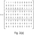
- Fig. 3 is a representation of a LDPC code using a parity-check matrix representation (see Fig. 3(a) ) and a graphical representation (see Fig. 3(b) ).
- Fig. 3(a) shows an example of a LDPC matrix H with a dimension n ⁇ m for a length 12 (3,4)-regular Gallager parity-check matrix (see for example reference [1]).
- Fig. 3(b) is a graphical representation for the partity-check matrix H shown in Fig. 3(a) using a bipartite graph, such as the Tanner graph.
- the Tanner graph includes two types of nodes which are called variable nodes and check or parity-check nodes.
- the graph includes m check nodes which correspond to the number of parity bits, and n variable nodes which correspond to the overall number of bits in a codeword.
- a check node i is connected to a variable node j if, and only if, the element h ij of H is a "one".
- the Tanner graph depicted in Fig. 3(b) is a subclass of bipartite graphs for graphically representing a LDPC code.
- the structure of the LDPC codes is exploited to estimate the decodability of an entire codeword before actually all parts of the codeword have been received, which is also referred to as an aggressive predictive HARQ feedback.
- the advantage is that the latency may be decreased as an HARQ retransmission may be performed earlier.
- the savings may be due to the early feedback which is returned to the sender or transmitter before the whole or entire codeword is received. Further, savings may be obtained due to the reduced estimation complexity as only a part of the codeword needs to be estimated.
- the generated codeword " b " may be described by the variable nodes and the check nodes using, for example, the Tanner graph.
- a subcode or subcodeword is selected from the codeword " b ".
- the subcode or subcodeword is known both at the transmitter and at the receiver, and is constructed from the original codeword " b ", also referred to as the mother code.
- a set of check nodes with all associated variable nodes is selected or chosen from the mother code so as to define the subcode.
- the subcode is defined by selected variable nodes associated with the set of check nodes, and the subcode may also be a parity-check code.
- the receiver may estimate the decodability of the subcodeword, for example, by employing a maximum-likelihood (ML) decoder. On the basis of the decodability of the codeword is evaluated.
- ML maximum-likelihood
- a belief-propagation based decoder may be used, such as an adjusted min-sum decoder or a sum-product decoder.
- the above mentioned decoders may determine a variable node reliability (VNR) as described in reference [2] on the basis of which the decodability may be judged.
- VNR variable node reliability
- the transmitter reorders the variable nodes defining the subcodeword of the known subcode in such a way that the variable nodes which are associated with the chosen check node are transmitted first over the channel, so as to allow for an initial decoding estimation, starting with the nodes associated with the subcodeword which is known at the receiver.
- the estimation of the decodability of the codeword currently transmitted may start before the entire codeword has been received.
- the receiver may request additional redundancy or may signal to the transmitter that no more redundancy is needed, because it is estimated that the codeword received is decodable or is likely to be decodable.
- the transmitter may stop sending redundancy to avoid unnecessary retransmissions and reduce latencies during the data transmission. Instead, the transmitter may already start sending the next codeword, in case a new codeword is to be transmitted.
- the receiver may not send a signal to the transmitter in case it is estimated that the codeword received is decodable or is likely to be decodable.
- the transmitter may transmit, during the next transmission the redundancy, if explicitly requested by the receiver, otherwise, the transmitter transmits a new codeword, if available. In case no new codeword is available for the receiver during the next transmission and in case no redundancy is requested, the transmitter will not send information for the receiver during the next transmission.
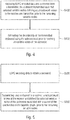
- Fig. 4 is a flow diagram of a method for processing received data at a receiver in accordance with an embodiment of the present invention.
- the receiver receives the LDPC encoded data over the channel from the transmitter.
- the codeword is transmitted in the above described way such that selected variable nodes defining the subcodeword are transmitted prior to the remaining variable nodes of the codeword. This allows the receiver in step S402 to estimate the decodability of the transmitted codeword using the subcodeword and to evaluate the decodability of the currently transmitted codeword, prior to receiving all variable nodes of the codeword.
- Fig. 5 is a flow diagram representing a method for preparing data to be transmitted by a transmitter in accordance with embodiments of the present invention.
- the transmitter or sender after having received data to be transmitted, in a first step S500 performs an LDPC encoding of the data so as to obtain a codeword.
- those variable nodes are selected which define a subcodeword which is known at the transmitter and at the receiver and which is used for estimating the decodability of the overall codeword at the receiver.
- the subcodeword is transmitted first, i.e., the selected variable nodes of the codeword defining the subcodeword are transmitted prior to the remaining variable nodes of the codeword.
- the transmitter provides the information for allowing an early estimation of the decodability of the entire codeword at the receiver.
- the VNR as described in reference [3] may be used to evaluate the decodability of the subcode or subcodeword.
- An offset min-sum algorithm with an offset of 0.26 may be used.
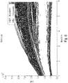
- Fig. 6 shows the evolution of the VNR over min-sum iterations, and the lines in the graph correspond to one transmitted codeword over a 0dB AWGN (average additive white Gaussian noise) channel.
- AWGN average additive white Gaussian noise
- a graph is shown having white lines/areas referred to as “undecodable” (the associated VNR values are correlated with a non-decodability of the entire codeword), and black lines/areas referred to, on the other hand, as “decodable” (the associated VNR values are correlated with a decodability of the entire codeword or indicate that the entire codeword may be reliably decoded).
- a threshold may be defined to predict the decodability of the entire codeword on the basis of the VNR.
- the threshold may be selected or set dependent on the false positive rate and the false negative rate obtained from the VNR estimations described above with reference to Fig. 6 .
- the false positive rate indicates that a codeword which has been predicted or estimated to be decodable (so that no retransmission will be triggered), was incorrect because the actual codeword received as a whole is undecodable.
- the false negative rate indicates that a codeword which has been predicted or estimated to be undecodable (so that a retransmission will be triggered), was incorrect, i.e.
- the false positive rate is more critical than the false negative rate as it results in an increase in the delay until additional redundancy for allowing decoding of the entire codeword is received at the receiver.
- the threshold may be selected as a trade-off between the two measures, namely, between the false positive rate and the false negative rate.
- Fig. 7 shows a graph representing the false negative and false positive rates over a normalized VNR threshold.
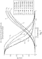
- Fig. 8 shows a graph representing the results of system level simulations in high load scenarios.
- Fig. 8 shows that in the "reliable" scenario (see curve a), the system always transmits with a rate of 1/6, thereby blocking two resources.
- a rate of 1/3 is used, and a conventional HARQ procedure is employed which results in a 4 TTIs (4 ms) RTT.
- curve c also referred to as predictive HARQ or P-HARQ
- a rate of 1/3 is used first and the prediction is performed using the subcodeword which is transmitted first.
- Fig. 8 shows that the reliable scenario (curve a) suffers from a resource shortage which causes high delays, and that the normal scenario (see curve b) does not provide for a higher throughput within a limited delay, for example, within two milliseconds.
- the inventive approach is advantageous as the incremental redundancy is directly transmitted in the next TTI, rather than waiting for additional TTIs as required in the normal scheme or even longer as required in the reliable scheme.
- a subcodeword which is known at the transmitter and at the receiver, is used to allow for an early estimation of the decodability of a codeword currently transmitted to a receiver, for example, on the basis of the VNR as described in reference [3].
- this is achieved by transmitting the subcodeword to the receiver first.
- the known subcodeword is defined using the information elements or bits from the codeword generated on the basis of the data to be transmitted.
- a plurality of variable nodes associated with a plurality of check nodes of a bipartite graph are selected to define the subcodeword, for example, to select a specific bit pattern representing the subcodeword.
- those bits or information elements representing the subcodeword are transmitted first so that the receiver may perform the estimation as to whether the entire codeword is decodable or not prior to receiving the complete codeword on the basis of the received subcodeword.
- the inventive approach may cause the receiver to request, responsive to the estimation indicating that the codeword cannot be decoded, a retransmission, or to signal, responsive to the estimation indicating that the codeword can be decoded, to the transmitter to stop transmitting additional redundancy for the currently transmitted codeword.
- a retransmission or to signal, responsive to the estimation indicating that the codeword can be decoded, to the transmitter to stop transmitting additional redundancy for the currently transmitted codeword.
- it may be determined that in a next transmission no further redundancy about the currently transmitted codeword (current transmission) is needed.
- the currently transmitted codeword can be fully decoded at the receiver, and, in case there is a new codeword to be transmitted in the next transmission, the new codeword may be transmitted.
- the additional redundancy may be transmitted so that the codeword transmitted in the first transmission may by decoded using the original codeword including information and redundancy from the first transmission and the additional redundancy from the second or re-transmission.
- FIG. 9 An embodiment of the inventive predictive HARQ process is schematically depicted in Fig. 9 .
- the upper arrow in Fig. 9 shows an eNB time line, and the lower arrow shows a UE time line.
- the base station transmits the data signal, for example, in the form of a data packet.
- the transmission of the packet starts.
- the packet is transmitted over the wireless or wired channel and is received at the receiver at the time t 2 .
- the time for receiving the packet completely is the TTI (transmission time interval) having a predefined duration or length.
- TTI transmission time interval
- the subcodeword is transmitted first, and is received at a time t 3 .
- the decodability of the transmitted packet is evaluated or estimated on the basis of the subcodeword.
- the receiver receives the remaining parts of the packet, namely the remaining parts of the codeword not yet transmitted.
- the estimation result of the subcodeword is available at the receiver. It is assumed that the estimation indicates that the codeword or packet that is currently transmitted from the base station to the receiver is not decodable. This result is signaled to the base station.
- the base station sends the additional redundancy for decoding the codeword.
- the additional redundancy is available, and using the data received during the first TTI and buffered at the receiver and the additional redundancy received during the second TTI, the codeword sent by the base station at time t 1 can now be decoded at the receiver.
- the additional redundancy may include chase combining or incremental redundancy.
- Fig. 9 shows that the inventive approach accelerates the process for decoding data or packets which, initially, are found to be not decodable at the receiver.
- the request for additional redundancy will start only once the first TTI has been completed, namely at the time t 5 and the advantage in terms of reduced delay is readily recognizable from Fig. 9.
- Fig. 9 shows that the receiver performs the decodability estimation and sends a signal to request further redundancy, in case the estimation shows that the packet currently transmitted cannot be decoded at the receiver on the basis of the information obtained during the first TTI.
- the receiver instead of sending a request signal to the base station at the time t 4 , the receiver, at the time t 3 sends a signal to the base station in the form of a stop signal.
- the base station at the time t 4 , will start sending the next packet which will then be processed in the second TTI in the same way as the first packet received at the time t 2 at the receiver.
- the codeword received during the first TTI and estimated to be decodable will be decoded by the receiver.
- the transmitter may signal to the receiver an order of the check nodes defining the codeword so that following the transmission in accordance with the inventive approach the decodable codeword can be reconstructed at the receiver for correct decoding.
- this decoding despite the estimated decodability, fails (false positive indication), a conventional retransmission process may be triggered to obtain additional redundancy available.
- the additional redundancy may include new data obtained through coupling.
- the packet transmitted from the base station towards the receiver may include a codeword representing both first data and redundancy. From the codeword the subcodeword known at the receiver is selected and used for estimating the decodability of the currently transmitted codeword. In case it is determined at the time t 3 (see Fig. 9 ) that the codeword is not decodable, at the time t 4 the additional redundancy is sent by the base station, and the additional redundancy includes new data obtained through coupling of LDPC codes, also referred to as spatial coupling (see for example reference [5]).
- LDPC codes also referred to as spatial coupling
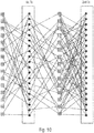
- FIG. 10 shows a schematic representation of the coupling of two codewords representing first data and second data as described in reference [5].
- the additional redundancy including the new data obtained through coupling is sent.
- the redundancy may be selected so that the information bits for the first and second data may be decoded. This is advantageous due to the increased time diversity of the joint codeword.
- the decodability may be estimated using information associated with all of the plurality of check nodes of the bipartite graph defining the subcodeword.
- the decodability may be estimated by initially estimating the decodability of the codeword using information associated with a first number of the plurality of check nodes of the bipartite graph defining the subcodeword. In case the estimation indicates that the codeword cannot be decoded, the decodability of the codeword is estimated using information associated with a second number of the plurality of check nodes of the bipartite graph defining the subcodeword. The second number is higher than the first number. In case the estimation still indicates that the codeword cannot be decoded, the estimation of the decodability of the codeword may be repeated using an increasing number of the plurality of check nodes of the bipartite graph defining the subcodeword.
- Estimating the decodability of the codeword may be repeated until a predefined number of the plurality of check nodes of the bipartite graph defining the subcodeword has been used, and/or until a time is reached to signal the transmitter that additional redundancy is needed or not such that at the beginning of the next transmission interval the additional redundancy or a new codeword is received.
- the information associated with some or all of the plurality of check nodes of the bipartite graph defining the subcodeword is transmitted in a fixed or in an arbitrary order.
- the receiver may perform an evaluation of the estimation, so as to obtain a level of confidence of the estimation result.
- the additional level of confidence may be taken into consideration when deciding whether the base station is to be requested for additional redundancy in any of the above described ways.
- the above described VNR thresholds may be used to define such levels of confidence.
- the receiver may perform, for example, a two or more bit predictive-HARQ feedback. According to the confidence level, the transmitter may decide how much redundancy is needed for the HARQ retransmission.
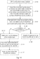
- Fig. 11 is a flow diagram of the inventive predictive HARQ process in accordance with an embodiment.
- Data is received at a base station which will be transmitted over the wireless or wired communication network to a user equipment
- the data is LDPC encoded to obtain a codeword.
- the codeword is transmitted over the channel. The transmission is such that selected variable nodes are transmitted prior to the remaining variable nodes.
- the selected variable nodes define a subcodeword that is known at the receiver and that is transmitted as first part of the codeword.
- a step S1104 the decodability of the codeword received is estimated at the receiver using the subcodeword prior to receiving all variable nodes of the codeword (see Fig. 9 ).
- step S1106 it is determined whether the estimation in step S1104 indicated that the currently transmitted codeword can be decoded. In case this is true, the method, at step S1108 signals to the transmitter that it is not necessary to transmit any additional redundancy so that, at the end of the first TTI (see Fig. 9 ), transmission of the redundancy including the new data obtained through coupling may be started. As mentioned above, in accordance with other embodiments, no signaling to the transmitter is performed when step S1106 indicates that the currently transmitted codeword can be decoded. There is no step S1108 in such an embodiment.
- step S1110 requests from the transmitter additional redundancy.
- the additional steps S1112 and S1114 may be optionally provided.
- a level of confidence of the estimation result is determined, as discussed above in detail.
- the redundancy to be requested from the transmitter at the time t 3 is determined so that the determined additional redundancy is requested from the transmitter at step S1110.
- all of the steps just described with reference to Fig. 11 may be combined, while other embodiments may not include steps S1108, S1112 and/or S1114.
- the present invention is not limited to such a code. Rather, any other code may be used, which is represented by variable nodes associated with a one or more check nodes of a bipartite graph so that a codewords generated using the code is defined by a plurality of the variable nodes associated with a plurality of the check nodes of the bipartite graph. Further, the present invention is not limited to a Tanner graph, rather, other bipartite graphs, like a factor graph, may be used.
- the subcodeword has been described to be defined by selected variable nodes associated with a subset of the check nodes of the bipartite graph.
- the code may be generated such that predefined variable nodes associated with a subset of the check nodes of the bipartite graph define the subcodeword, for example one or more consecutive variable nodes starting with a first one of the variable nodes.
- the first variable nodes of the codeword define the subcodeword.
- the estimation has been described to be performed on the basis of the subcodeword.
- the present invention is not limited to such embodiments.
- the estimation may take into account additional parameters, like the channel quality, the channel estimation, additional CRC symbols, etc.
- variable nodes defining the subcodeword are sent prior to the remaining variable nodes.
- present invention is not limited to such embodiments.
- one or more variable nodes of the codeword, which do not define the subcodeword may be send ahead of those variable nodes defining the subcodeword.
- variable nodes of the codeword which do not define the subcodeword, may be send to such an extent that when sending the subcodeword, the estimation of the decodability at the receiver can be performed such that it can still be signaled to the transmitter that additional redundancy is needed or not and such that at the beginning of the next transmission interval the additional redundancy or, in case there is a new codeword for the receiver, the new codeword is received.
- aspects of the described concept have been described in the context of an apparatus, it is clear that these aspects also represent a description of the corresponding method, where a block or a device corresponds to a method step or a feature of a method step. Analogously, aspects described in the context of a method step also represent a description of a corresponding block or item or feature of a corresponding apparatus.
- embodiments of the invention may be implemented in hardware or in software.
- the implementation may be performed using a digital storage medium, for example cloud storage, a floppy disk, a DVD, a Blue-Ray, a CD, a ROM, a PROM, an EPROM, an EEPROM or a FLASH memory, having electronically readable control signals stored thereon, which cooperate (or are capable of cooperating) with a programmable computer system such that the respective method is performed. Therefore, the digital storage medium may be computer readable.
- Some embodiments according to the invention comprise a data carrier having electronically readable control signals, which are capable of cooperating with a programmable computer system, such that one of the methods described herein is performed.
- embodiments of the present invention may be implemented as a computer program product with a program code, the program code being operative for performing one of the methods when the computer program product runs on a computer.
- the program code may for example be stored on a machine readable carrier.
- inventions comprise the computer program for performing one of the methods described herein, stored on a machine readable carrier.
- an embodiment of the inventive method is, therefore, a computer program having a program code for performing one of the methods described herein, when the computer program runs on a computer.
- a further embodiment of the inventive methods is, therefore, a data carrier (or a digital storage medium, or a computer-readable medium) comprising, recorded thereon, the computer program for performing one of the methods described herein.
- a further embodiment of the inventive method is, therefore, a data stream or a sequence of signals representing the computer program for performing one of the methods described herein. The data stream or the sequence of signals may for example be configured to be transferred via a data communication connection, for example via the Internet.
- a further embodiment comprises a processing means, for example a computer, or a programmable logic device, configured to or adapted to perform one of the methods described herein.
- a further embodiment comprises a computer having installed thereon the computer program for performing one of the methods described herein.
- a programmable logic device for example a field programmable gate array
- a field programmable gate array may cooperate with a microprocessor in order to perform one of the methods described herein.
- the methods are preferably performed by any hardware apparatus.
- estimating the decodability of the transmitted codeword may take into account in addition one or more of the channel quality, the channel estimation, and CRC symbols.
- a conventional retransmission process may be triggered to obtain additional redundancy available.
- the receiver when the receiver performs an evaluation of the estimation, so as to obtain a level of confidence of the estimation result, based on the confidence, the receiver may perform, for example, a two or more bit predictive-HARQ feedback and/or according to the confidence level, the transmitter may decide how much redundancy is needed for the HARQ retransmission.
Landscapes
- Engineering & Computer Science (AREA)
- Computer Networks & Wireless Communication (AREA)
- Signal Processing (AREA)
- Physics & Mathematics (AREA)
- Probability & Statistics with Applications (AREA)
- Theoretical Computer Science (AREA)
- Detection And Prevention Of Errors In Transmission (AREA)
- Mobile Radio Communication Systems (AREA)
- Error Detection And Correction (AREA)
Abstract
Description
- The present invention concerns the field of wireless or wired communication networks or systems, more specifically, communication networks in which signal transmission is susceptible to noise so that a retransmission of data and/or redundancy is requested. Embodiments of the invention concern an improved retransmission process in a communication network using, e.g., a predictive hybrid automatic repeat request (HARQ) for low-density parity-check (LDPC) codes.
-
Fig. 1 is a schematic representation of an example of a network infrastructure, such as a wireless communication network or wireless communication system, including a plurality of base stations eNB1 to eNB5, each serving a specific area surrounding the base station schematically represented by therespective cells 1001 to 1005. The base stations are provided to serve users within a cell. A user may be a stationary device or a mobile device. Further, the wireless communication system may be accessed by loT devices which connect to a base station or to a user. IoT devices may include physical devices, vehicles, buildings and other items having embedded therein electronics, software, sensors, actuators, or the like as well as network connectivity that enable these devices to collect and exchange data across an existing network infrastructure.Fig. 1 shows an exemplary view of only five cells, however, the wireless communication system may include more such cells.Fig. 1 shows two users UE1 and UE2, also referred to as user equipment (UE), that are incell 1002 and that are served by base station eNB2. Another user UE3 is shown incell 1004 which is served by base station eNB4. Thearrows Fig. 1 shows twoloT devices cell 1004, which may be stationary or mobile devices. TheloT device 1041 accesses the wireless communication system via the base station eNB4 to receive and transmit data as schematically represented by arrow 1061. TheloT device 1042 accesses the wireless communication system via the user UE3 as is schematically represented by arrow 1062. - The wireless communication system may be any single-tone or multicarrier system based on frequency-division multiplexing, like the orthogonal frequency-division multiplexing (OFDM) system, the orthogonal frequency-division multiple access (OFDMA) system, or any other IFFT-based signal with or without CP, e.g. DFT-s-OFDM. Other waveforms, like non-orthogonal waveforms for multiple access, e.g. filter-bank multicarrier (FBMC), generalized frequency division multiplexing (GFDM) or universal filtered multi carrier (UFMC), may be used.
- Data may also be communicated over channels of a wired communication network or a combination of wired and wireless networks, for example, a local area network (LAN), a G.hn network operating over different types of wires like telephone wires, coaxial cables and/or power lines, or a wide area network (WAN) such as the internet.
- In the above referenced networks data may be overlaid with noise while being transmitted over the channel so that the data may not be processed correctly or may not be processed at all at the receiver. For example, when the data to be transmitted is encoded using a predefined code, a codeword representing the data is generated at the transmitter and forwarded to the receiver over the channel. During the transmission, the codeword may be overlaid with noise to such an extent that decoding of the codeword is not possible, e.g., because of noisy channel situations. To address such a situation, wired and/or wireless communication networks may employ a retransmission mechanism. For example, when the receiver detects that a received codeword cannot be decoded, a retransmission from the transmitter or sender is requested. For example, a HARQ (hybrid automatic repeat request) may be used to request a retransmission from the transmitter to correct decoding failures. For example, additional redundancy may be requested. At the transmitter, encoding the data includes generating redundancy that may include redundant bits that are added to the data to be transmitted. During a first transmission only a part of the redundancy may be transmitted. When a retransmission is requested, further parts of the redundancy may be send to the receiver. For example, HARQ may employ chase combining (every re-transmission contains the same information - data and parity bits), or incremental redundancy (every re-transmission contains different information than the previous one).
- The retransmission, however, causes a delay due to the additional round-trip time (RTT) which includes the propagation delays over the network and the processing delays at the UE and the eNB. Thus, in communication networks it is desired to reduce delays caused due to erroneous data transmissions and associated retransmission requests.
- It is an object of the present invention to provide an approach improving a retransmission process in a communication network.
- This object is achieved by the subject matter as defined in the independent claims.
- Embodiments are defined in the dependent claims.
- Embodiments of the present invention are now described in further detail with reference to the accompanying drawings, in which:
- Fig. 1
- shows a schematic representation of an example of a wireless communication system;
- Fig. 2
- is a schematic representation of a wireless communication system for transmitting information from a transmitter to a receiver;
- Fig. 3
- is a representation of a LDPC code using a matrix representation (see
Fig. 3(a) ) and a graphical representation (seeFig. 3(b) ); - Fig. 4
- is a flow diagram of a method for processing received data at a receiver in accordance with an embodiment of the present invention;
- Fig. 5
- is a flow diagram representing a method for preparing data to be transmitted by a transmitter in accordance with embodiments of the present invention;
- Fig. 6
- shows the evolution of the variable node reliability over min-sum iterations, for codewords transmitted over a 0dB AWGN channel;
- Fig. 7
- shows a graph representing false negative and false positive rates over a normalized VNR threshold;
- Fig. 8
- shows a graph representing the results of system level simulations in high load scenarios;
- Fig. 9
- schematically depicts an embodiment of the predictive HARQ process in accordance with the present invention;
- Fig. 10
- is a schematic representation of the coupling of two codewords representing first data and second data; and
- Fig. 11
- is a flow diagram of the inventive predictive HARQ process in accordance with an embodiment of the present invention.
- In the following, preferred embodiments of the present invention are described in further detail with reference to the enclosed drawings in which elements having the same or similar function are referenced by the same reference signs.
- Embodiments of the present invention may be implemented in a wireless communication system as depicted in
Fig. 1 including base stations and UEs, like mobile terminals or loT devices.Fig. 2 is a schematic representation of a wireless communication system for communicating information between a base station BS and a UE. The base station BS includes one or more antennas ANTBS or an antenna array having a plurality of antenna elements. The UE includes one or more antennas ANTUE. As is indicated by thearrow 102 signals are communicated between the base station BS and the UE via a wireless communication link, like a radio link. The wireless communication system may operate in accordance with the embodiments described herein. - In accordance with embodiments, for example in case of a downlink data transmission in the wireless communication network, the base station BS includes a low-density parity-check (LDPC) encoder/
decoder 108 coupled to a transmit/receiveunit 110 which, in turn, is connected to the one or more antennas ANTeNB. When the base station operates as a transmitter, the LDPC encoder/decoder 108 receives data to be transmitted to the UE, which operates as a receiver, over the communication link orchannel 102. The LDPC encoder/decoder 108 encodes the data using a low-density parity-check (LDPC) code to obtain a codeword. The codeword is defined by a plurality of variable nodes associated with a plurality of the check nodes of a bipartite graph representing the LDPC code. The transmit/receiveunit 110 transmits the codeword over thechannel 102 to the UE such that selected variable nodes associated with a subset of the check nodes of the bipartite graph are transmitted prior to the remaining variable nodes. The selected variable nodes define a subcodeword known at the UE. The subcodeword is used by the UE to estimate a decodability of the transmitted codeword prior to receiving all variable nodes of the codeword. The UE includes a LDPC encoder/decoder 112 coupled to a transmit/receiveunit 114 which, in turn, is connected to the one or more antennas ANTUE. When the UE operates as a receiver, the UE receives from the base station eNB, which operates as a transmitter, over the communication link or channel 102 adata signal 116. The LDPC encoder/decoder 112 receives over the via the one or more antennas ANTUE and the transmit/receiveunit 114 the data signal 116 to be decoded. The codeword is transmitted over thechannel 102 such that the subcodeword is transmitted prior to the remaining variable nodes of the codeword. The LDPC encoder/decoder 112 estimates the decodability of the transmitted codeword using the subcodeword prior to receiving all variable nodes of the codeword. - In accordance with other embodiments, for example in case of an uplink data transmission in the wireless communication network, the UE is the transmitter and the base station eNB is the receiver.
- As mentioned above,
Fig. 2 schematically represents the data signal 116 transmitted over thechannel 102. In accordance with embodiments the data signal 116 includes the data to be transmitted from the transmitter to the receiver over thechannel 102. The data is encoded using a LDPC code so as to obtain a codeword. The codeword is defined by the plurality of variable nodes associated with the plurality of check nodes of the bipartite graph representing the LDPC code. The data signal 116 includes afirst part 116a including a subcodeword that is known at the receiver. The subcodeword is defined by selected variable nodes associated with a subset of the check nodes of the bipartite graph. The data signal 116 further includes asecond part 116b including the remaining parts of the codeword defined by the remaining variable nodes. As is schematically represented inFig. 2 , thefirst part 116a precedes thesecond part 116b so that, upon transmitting the data signal 116, thefirst part 116a is transmitted first, i.e., prior to thesecond part 116b. In other words, thesecond part 116b follows the first part so that the estimation at the receiver can be performed prior to receiving the complete codeword or complete data signal 116 representing the codeword. - Although
Fig. 2 represents, schematically, a wireless communication network, as mentioned above, the inventive approach may also be applied in the wired communication networks mentioned above. - The inventive approach allows for a decodability estimation prior to receipt of the
complete data signal 116, also referred to as data packet or codeword. Thus, at a time at which parts of the codeword are still received, the receiver may already determine whether the currently transmitted codeword may be decoded or not. In case decodability is determined to be not possible, i.e., the received codeword cannot be decoded by the receiver, or in case it is determined that it is unlikely that the received codeword can be decoded, an early retransmission may be triggered to request the codeword to be retransmitted or to request additional redundancy not yet transmitted. This reduces the delay as, other than in conventional approaches, the retransmission may be requested before the current transmission, e.g. the current TTI, is completed, and the transmitter may send the requested additional redundancy during the very next transmission, e.g. during the next TTI. This enhancement of the retransmission process and the associated reduction of delays shall now be discussed in further detail below with reference to specific, nonlimiting embodiments. - In accordance with the present invention, data to be transmitted over a channel of a communication network is encoded using low-density parity-check (LDPC) codes which are a class of linear block codes. A LDPC code may be described using a matrix and/or a graphical representation.
Fig. 3 is a representation of a LDPC code using a parity-check matrix representation (seeFig. 3(a) ) and a graphical representation (seeFig. 3(b) ).Fig. 3(a) shows an example of a LDPC matrix H with a dimension n × m for a length 12 (3,4)-regular Gallager parity-check matrix (see for example reference [1]). In general in a low-density parity-check matrix the number of ones in each row and the number of ones in each column is much smaller than n and m, respectively.Fig. 3(b) is a graphical representation for the partity-check matrix H shown inFig. 3(a) using a bipartite graph, such as the Tanner graph. The Tanner graph includes two types of nodes which are called variable nodes and check or parity-check nodes. The graph includes m check nodes which correspond to the number of parity bits, and n variable nodes which correspond to the overall number of bits in a codeword. A check node i is connected to a variable node j if, and only if, the element hij of H is a "one". The Tanner graph depicted inFig. 3(b) is a subclass of bipartite graphs for graphically representing a LDPC code. - In accordance with the inventive approach, the structure of the LDPC codes is exploited to estimate the decodability of an entire codeword before actually all parts of the codeword have been received, which is also referred to as an aggressive predictive HARQ feedback. The advantage is that the latency may be decreased as an HARQ retransmission may be performed earlier. The savings may be due to the early feedback which is returned to the sender or transmitter before the whole or entire codeword is received. Further, savings may be obtained due to the reduced estimation complexity as only a part of the codeword needs to be estimated.
- In accordance with the present invention, a codeword "b" to be transmitted over the channel may be calculated on the basis of a vector representing the data bits "a" to be transmitted, and on the basis of a generator matrix G as follows: b = a ⊗ G , and for "b" it holds that 0 = H ⊗ bT , wherein ⊗ represents a matrix multiplication, for example, using a modulo-2 arithmetic. The generated codeword "b" may be described by the variable nodes and the check nodes using, for example, the Tanner graph. In accordance with the present invention, rather than transmitting the generated codeword "b" over the channel, a subcode or subcodeword is selected from the codeword "b". The subcode or subcodeword is known both at the transmitter and at the receiver, and is constructed from the original codeword "b", also referred to as the mother code.
- In accordance with embodiments, a set of check nodes with all associated variable nodes is selected or chosen from the mother code so as to define the subcode. In other words, the subcode is defined by selected variable nodes associated with the set of check nodes, and the subcode may also be a parity-check code. The receiver may estimate the decodability of the subcodeword, for example, by employing a maximum-likelihood (ML) decoder. On the basis of the decodability of the codeword is evaluated. In accordance with other embodiments, to reduce the implementation complexity, other decoders may be used. A belief-propagation based decoder may be used, such as an adjusted min-sum decoder or a sum-product decoder. The above mentioned decoders may determine a variable node reliability (VNR) as described in reference [2] on the basis of which the decodability may be judged.
- In accordance with the present invention, the transmitter reorders the variable nodes defining the subcodeword of the known subcode in such a way that the variable nodes which are associated with the chosen check node are transmitted first over the channel, so as to allow for an initial decoding estimation, starting with the nodes associated with the subcodeword which is known at the receiver. Thus, the estimation of the decodability of the codeword currently transmitted may start before the entire codeword has been received. Dependent on the result of the estimate, the receiver may request additional redundancy or may signal to the transmitter that no more redundancy is needed, because it is estimated that the codeword received is decodable or is likely to be decodable. In this case, the transmitter may stop sending redundancy to avoid unnecessary retransmissions and reduce latencies during the data transmission. Instead, the transmitter may already start sending the next codeword, in case a new codeword is to be transmitted. In accordance with further embodiments, the receiver may not send a signal to the transmitter in case it is estimated that the codeword received is decodable or is likely to be decodable. The transmitter may transmit, during the next transmission the redundancy, if explicitly requested by the receiver, otherwise, the transmitter transmits a new codeword, if available. In case no new codeword is available for the receiver during the next transmission and in case no redundancy is requested, the transmitter will not send information for the receiver during the next transmission.
-
Fig. 4 is a flow diagram of a method for processing received data at a receiver in accordance with an embodiment of the present invention. In a first step S400, the receiver receives the LDPC encoded data over the channel from the transmitter. The codeword is transmitted in the above described way such that selected variable nodes defining the subcodeword are transmitted prior to the remaining variable nodes of the codeword. This allows the receiver in step S402 to estimate the decodability of the transmitted codeword using the subcodeword and to evaluate the decodability of the currently transmitted codeword, prior to receiving all variable nodes of the codeword. -
Fig. 5 is a flow diagram representing a method for preparing data to be transmitted by a transmitter in accordance with embodiments of the present invention. The transmitter or sender, after having received data to be transmitted, in a first step S500 performs an LDPC encoding of the data so as to obtain a codeword. On the basis of the codeword, those variable nodes are selected which define a subcodeword which is known at the transmitter and at the receiver and which is used for estimating the decodability of the overall codeword at the receiver. In step S502 the subcodeword is transmitted first, i.e., the selected variable nodes of the codeword defining the subcodeword are transmitted prior to the remaining variable nodes of the codeword. The transmitter provides the information for allowing an early estimation of the decodability of the entire codeword at the receiver. - In the following an embodiment is described using a code having a codeword with a rate of 1/3 and an incremental redundancy which may be transmitted with a code rate of 1/6. The VNR, as described in reference [3] may be used to evaluate the decodability of the subcode or subcodeword. An offset min-sum algorithm with an offset of 0.26 may be used.
Fig. 6 shows the evolution of the VNR over min-sum iterations, and the lines in the graph correspond to one transmitted codeword over a 0dB AWGN (average additive white Gaussian noise) channel. As may be seen fromFig. 6 , there is a correlation between the decodability of the entire codeword and the VNR of the subcodeword. InFig. 6 , a graph is shown having white lines/areas referred to as "undecodable" (the associated VNR values are correlated with a non-decodability of the entire codeword), and black lines/areas referred to, on the other hand, as "decodable" (the associated VNR values are correlated with a decodability of the entire codeword or indicate that the entire codeword may be reliably decoded). - In accordance with embodiments, on the basis of the information in
Fig. 6 and dependent on a desired working point, a threshold may be defined to predict the decodability of the entire codeword on the basis of the VNR. The threshold may be selected or set dependent on the false positive rate and the false negative rate obtained from the VNR estimations described above with reference toFig. 6 . The false positive rate indicates that a codeword which has been predicted or estimated to be decodable (so that no retransmission will be triggered), was incorrect because the actual codeword received as a whole is undecodable. The false negative rate indicates that a codeword which has been predicted or estimated to be undecodable (so that a retransmission will be triggered), was incorrect, i.e. after receipt at the receiver the codeword turned out to be decodable. The false positive rate is more critical than the false negative rate as it results in an increase in the delay until additional redundancy for allowing decoding of the entire codeword is received at the receiver. The threshold may be selected as a trade-off between the two measures, namely, between the false positive rate and the false negative rate.Fig. 7 shows a graph representing the false negative and false positive rates over a normalized VNR threshold. - The inventive approach may be evaluated on a system level.
Fig. 8 shows a graph representing the results of system level simulations in high load scenarios.Fig. 8 shows that in the "reliable" scenario (see curve a), the system always transmits with a rate of 1/6, thereby blocking two resources. In the "normal" scenario (see curve b), a rate of 1/3 is used, and a conventional HARQ procedure is employed which results in a 4 TTIs (4 ms) RTT. In accordance with the inventive approach (see curve c), also referred to as predictive HARQ or P-HARQ, a rate of 1/3 is used first and the prediction is performed using the subcodeword which is transmitted first. Based on a prediction indicating that the codeword transmitted in the current TTI cannot be decoded, the incremental redundancy is transmitted directly in the next TTI thereby reducing the delay.Fig. 8 shows that the reliable scenario (curve a) suffers from a resource shortage which causes high delays, and that the normal scenario (see curve b) does not provide for a higher throughput within a limited delay, for example, within two milliseconds. However, the inventive approach (see curve c) is advantageous as the incremental redundancy is directly transmitted in the next TTI, rather than waiting for additional TTIs as required in the normal scheme or even longer as required in the reliable scheme. - In the embodiments described so far a subcodeword, which is known at the transmitter and at the receiver, is used to allow for an early estimation of the decodability of a codeword currently transmitted to a receiver, for example, on the basis of the VNR as described in reference [3]. In accordance with the inventive approach, this is achieved by transmitting the subcodeword to the receiver first. The known subcodeword is defined using the information elements or bits from the codeword generated on the basis of the data to be transmitted. A plurality of variable nodes associated with a plurality of check nodes of a bipartite graph are selected to define the subcodeword, for example, to select a specific bit pattern representing the subcodeword. Rather than transmitting the codeword as encoded via the channel, in accordance with the inventive approach, those bits or information elements representing the subcodeword are transmitted first so that the receiver may perform the estimation as to whether the entire codeword is decodable or not prior to receiving the complete codeword on the basis of the received subcodeword.
- In accordance with further embodiments, the inventive approach may cause the receiver to request, responsive to the estimation indicating that the codeword cannot be decoded, a retransmission, or to signal, responsive to the estimation indicating that the codeword can be decoded, to the transmitter to stop transmitting additional redundancy for the currently transmitted codeword. In other words, dependent on the result of the estimation, it may be determined that in a next transmission no further redundancy about the currently transmitted codeword (current transmission) is needed. The currently transmitted codeword can be fully decoded at the receiver, and, in case there is a new codeword to be transmitted in the next transmission, the new codeword may be transmitted. In case the estimation indicates that the codeword, that is transmitted in the current transmission, is not decodable, in the next transmission, the additional redundancy may be transmitted so that the codeword transmitted in the first transmission may by decoded using the original codeword including information and redundancy from the first transmission and the additional redundancy from the second or re-transmission.
- An embodiment of the inventive predictive HARQ process is schematically depicted in
Fig. 9 . The upper arrow inFig. 9 shows an eNB time line, and the lower arrow shows a UE time line. At the time t1, the base station transmits the data signal, for example, in the form of a data packet. At the time t1 the transmission of the packet starts. The packet is transmitted over the wireless or wired channel and is received at the receiver at the time t2. The time for receiving the packet completely is the TTI (transmission time interval) having a predefined duration or length. In accordance with the inventive approach, in the packet the subcodeword is transmitted first, and is received at a time t3. The decodability of the transmitted packet is evaluated or estimated on the basis of the subcodeword. During the estimation the receiver receives the remaining parts of the packet, namely the remaining parts of the codeword not yet transmitted. InFig. 9 it is assumed that after the time t3 but before the end of the first TTI, the estimation result of the subcodeword is available at the receiver. It is assumed that the estimation indicates that the codeword or packet that is currently transmitted from the base station to the receiver is not decodable. This result is signaled to the base station. At the time t4 which is ahead of the end of the first TTI, the base station sends the additional redundancy for decoding the codeword. At the time t5 which is the end of the first TTI, the additional redundancy is available, and using the data received during the first TTI and buffered at the receiver and the additional redundancy received during the second TTI, the codeword sent by the base station at time t1 can now be decoded at the receiver. The additional redundancy may include chase combining or incremental redundancy. -
Fig. 9 shows that the inventive approach accelerates the process for decoding data or packets which, initially, are found to be not decodable at the receiver. In conventional approaches, the request for additional redundancy will start only once the first TTI has been completed, namely at the time t5 and the advantage in terms of reduced delay is readily recognizable fromFig. 9. Fig. 9 shows that the receiver performs the decodability estimation and sends a signal to request further redundancy, in case the estimation shows that the packet currently transmitted cannot be decoded at the receiver on the basis of the information obtained during the first TTI. On the other hand, in case the estimation process yields that the packet can be decoded on the basis of the information received during the first TTI, instead of sending a request signal to the base station at the time t4, the receiver, at the time t3 sends a signal to the base station in the form of a stop signal. The base station, at the time t4, will start sending the next packet which will then be processed in the second TTI in the same way as the first packet received at the time t2 at the receiver. - The codeword received during the first TTI and estimated to be decodable will be decoded by the receiver. For the decoding, the transmitter may signal to the receiver an order of the check nodes defining the codeword so that following the transmission in accordance with the inventive approach the decodable codeword can be reconstructed at the receiver for correct decoding. In case this decoding, despite the estimated decodability, fails (false positive indication), a conventional retransmission process may be triggered to obtain additional redundancy available.
- In accordance with further embodiments, the additional redundancy may include new data obtained through coupling. For example, at the time t1 (see
Fig. 9 ), the packet transmitted from the base station towards the receiver may include a codeword representing both first data and redundancy. From the codeword the subcodeword known at the receiver is selected and used for estimating the decodability of the currently transmitted codeword. In case it is determined at the time t3 (seeFig. 9 ) that the codeword is not decodable, at the time t4 the additional redundancy is sent by the base station, and the additional redundancy includes new data obtained through coupling of LDPC codes, also referred to as spatial coupling (see for example reference [5]).Fig. 10 shows a schematic representation of the coupling of two codewords representing first data and second data as described in reference [5]. At the time t4 the additional redundancy including the new data obtained through coupling is sent. At the transmitter, the redundancy may be selected so that the information bits for the first and second data may be decoded. This is advantageous due to the increased time diversity of the joint codeword. - In accordance with embodiments of the present invention, the decodability may be estimated using information associated with all of the plurality of check nodes of the bipartite graph defining the subcodeword.
- In accordance with other embodiments of the present invention, the decodability may be estimated by initially estimating the decodability of the codeword using information associated with a first number of the plurality of check nodes of the bipartite graph defining the subcodeword. In case the estimation indicates that the codeword cannot be decoded, the decodability of the codeword is estimated using information associated with a second number of the plurality of check nodes of the bipartite graph defining the subcodeword. The second number is higher than the first number. In case the estimation still indicates that the codeword cannot be decoded, the estimation of the decodability of the codeword may be repeated using an increasing number of the plurality of check nodes of the bipartite graph defining the subcodeword. Estimating the decodability of the codeword may be repeated until a predefined number of the plurality of check nodes of the bipartite graph defining the subcodeword has been used, and/or until a time is reached to signal the transmitter that additional redundancy is needed or not such that at the beginning of the next transmission interval the additional redundancy or a new codeword is received.
- In accordance with yet other embodiments of the present invention, the information associated with some or all of the plurality of check nodes of the bipartite graph defining the subcodeword is transmitted in a fixed or in an arbitrary order.
- In accordance with further embodiments, the receiver may perform an evaluation of the estimation, so as to obtain a level of confidence of the estimation result. In addition to the actual estimation result, the additional level of confidence may be taken into consideration when deciding whether the base station is to be requested for additional redundancy in any of the above described ways. For example, the above described VNR thresholds (see
Fig. 7 ) may be used to define such levels of confidence. Based on the confidence, the receiver may perform, for example, a two or more bit predictive-HARQ feedback. According to the confidence level, the transmitter may decide how much redundancy is needed for the HARQ retransmission. -
Fig. 11 is a flow diagram of the inventive predictive HARQ process in accordance with an embodiment. Data is received at a base station which will be transmitted over the wireless or wired communication network to a user equipment At step S1100 the data is LDPC encoded to obtain a codeword. At step S1102 the codeword is transmitted over the channel. The transmission is such that selected variable nodes are transmitted prior to the remaining variable nodes. The selected variable nodes define a subcodeword that is known at the receiver and that is transmitted as first part of the codeword. A step S1104, the decodability of the codeword received is estimated at the receiver using the subcodeword prior to receiving all variable nodes of the codeword (seeFig. 9 ). At step S1106, it is determined whether the estimation in step S1104 indicated that the currently transmitted codeword can be decoded. In case this is true, the method, at step S1108 signals to the transmitter that it is not necessary to transmit any additional redundancy so that, at the end of the first TTI (seeFig. 9 ), transmission of the redundancy including the new data obtained through coupling may be started. As mentioned above, in accordance with other embodiments, no signaling to the transmitter is performed when step S1106 indicates that the currently transmitted codeword can be decoded. There is no step S1108 in such an embodiment. - In case it is determined at S1106 that the estimate indicates that the codeword is not decodable at the receiver, the inventive approach, at step S1110 requests from the transmitter additional redundancy. In accordance with further embodiments of the inventive approach, between steps S1106 and S1110 the additional steps S1112 and S1114 may be optionally provided. At S1112 a level of confidence of the estimation result is determined, as discussed above in detail. At step S1114, the redundancy to be requested from the transmitter at the time t3 (see
Fig. 9 ) is determined so that the determined additional redundancy is requested from the transmitter at step S1110. In accordance with embodiments, all of the steps just described with reference toFig. 11 may be combined, while other embodiments may not include steps S1108, S1112 and/or S1114. - Although the embodiments of the present invention as described above referred to the LDPC code, the present invention is not limited to such a code. Rather, any other code may be used, which is represented by variable nodes associated with a one or more check nodes of a bipartite graph so that a codewords generated using the code is defined by a plurality of the variable nodes associated with a plurality of the check nodes of the bipartite graph. Further, the present invention is not limited to a Tanner graph, rather, other bipartite graphs, like a factor graph, may be used.
- In the embodiments described so far, the subcodeword has been described to be defined by selected variable nodes associated with a subset of the check nodes of the bipartite graph. However, the present invention is not limited to such embodiments. In accordance with further embodiments, the code may be generated such that predefined variable nodes associated with a subset of the check nodes of the bipartite graph define the subcodeword, for example one or more consecutive variable nodes starting with a first one of the variable nodes. In accordance with such an embodiment, the first variable nodes of the codeword define the subcodeword.
- Further, in the embodiments described so far, the estimation has been described to be performed on the basis of the subcodeword. However, the present invention is not limited to such embodiments. In accordance with further embodiments, the estimation may take into account additional parameters, like the channel quality, the channel estimation, additional CRC symbols, etc.
- Further, in the embodiments described so far, the variable nodes defining the subcodeword are sent prior to the remaining variable nodes. However, the present invention is not limited to such embodiments. In accordance with further embodiments, one or more variable nodes of the codeword, which do not define the subcodeword, may be send ahead of those variable nodes defining the subcodeword. For example, variable nodes of the codeword, which do not define the subcodeword, may be send to such an extent that when sending the subcodeword, the estimation of the decodability at the receiver can be performed such that it can still be signaled to the transmitter that additional redundancy is needed or not and such that at the beginning of the next transmission interval the additional redundancy or, in case there is a new codeword for the receiver, the new codeword is received.
- Although some aspects of the described concept have been described in the context of an apparatus, it is clear that these aspects also represent a description of the corresponding method, where a block or a device corresponds to a method step or a feature of a method step. Analogously, aspects described in the context of a method step also represent a description of a corresponding block or item or feature of a corresponding apparatus.
- Depending on certain implementation requirements, embodiments of the invention may be implemented in hardware or in software. The implementation may be performed using a digital storage medium, for example cloud storage, a floppy disk, a DVD, a Blue-Ray, a CD, a ROM, a PROM, an EPROM, an EEPROM or a FLASH memory, having electronically readable control signals stored thereon, which cooperate (or are capable of cooperating) with a programmable computer system such that the respective method is performed. Therefore, the digital storage medium may be computer readable.
- Some embodiments according to the invention comprise a data carrier having electronically readable control signals, which are capable of cooperating with a programmable computer system, such that one of the methods described herein is performed.
- Generally, embodiments of the present invention may be implemented as a computer program product with a program code, the program code being operative for performing one of the methods when the computer program product runs on a computer. The program code may for example be stored on a machine readable carrier.
- Other embodiments comprise the computer program for performing one of the methods described herein, stored on a machine readable carrier. In other words, an embodiment of the inventive method is, therefore, a computer program having a program code for performing one of the methods described herein, when the computer program runs on a computer.
- A further embodiment of the inventive methods is, therefore, a data carrier (or a digital storage medium, or a computer-readable medium) comprising, recorded thereon, the computer program for performing one of the methods described herein. A further embodiment of the inventive method is, therefore, a data stream or a sequence of signals representing the computer program for performing one of the methods described herein. The data stream or the sequence of signals may for example be configured to be transferred via a data communication connection, for example via the Internet. A further embodiment comprises a processing means, for example a computer, or a programmable logic device, configured to or adapted to perform one of the methods described herein. A further embodiment comprises a computer having installed thereon the computer program for performing one of the methods described herein.
- In some embodiments, a programmable logic device (for example a field programmable gate array) may be used to perform some or all of the functionalities of the methods described herein. In some embodiments, a field programmable gate array may cooperate with a microprocessor in order to perform one of the methods described herein. Generally, the methods are preferably performed by any hardware apparatus.
- Further embodiments are now described.
- A 1st embodiment provides a receiver,
- wherein the receiver is configured to receive encoded data over a channel from a transmitter, wherein the data is encoded to obtain a codeword, wherein the codeword is defined by a plurality of variable nodes associated with a plurality of the check nodes of a bipartite graph representing the code, wherein the codeword is transmitted over the channel such that certain variable nodes, which are associated with a subset of the check nodes of the bipartite graph, are transmitted prior to other variable nodes, and
- wherein the certain variable nodes define a subcodeword known by the receiver; and wherein the receiver is configured to estimate a decodability of the transmitted codeword using the subcodeword prior to receiving all variable nodes of the codeword.
- A 2nd embodiment provides the receiver of the 1st embodiment, wherein, responsive to an estimation indicating that the codeword cannot be decoded, the receiver is configured to request from the transmitter additional redundancy.
- A 3rd embodiment provides the receiver of the 1st or 2nd embodiments, wherein, responsive to an estimation indicating that the codeword can be decoded, the receiver is configured to signal the transmitter to stop transmitting additional redundancy.
- A 4th embodiment provides the receiver of the 2nd or 3rd embodiments, wherein the receiver is configured to determine a level of confidence of the estimation result, and to determine, based on the level of confidence, the additional redundancy to request from the transmitter.
- A 5th embodiment provides the receiver of one of the 2nd to 4th embodiments, wherein the additional redundancy includes chase combining, or incremental redundancy, or additional redundancy including new data obtained through coupling.
- A 6th embodiment provides the receiver of one of the 1st to 5th embodiments, wherein the receiver is configured to estimate the decodability of the codeword using information associated with all of the plurality of check nodes of the bipartite graph defining the subcodeword.
- A 7th embodiment provides the receiver of one of the 1st to 5th embodiments, wherein the receiver is configured to initially estimate the decodability of the codeword using information associated with a first number of the plurality of check nodes of the bipartite graph defining the subcodeword, and wherein, responsive to an estimation indicating that the codeword cannot be decoded, the receiver is configured to estimate the decodability of the codeword using information associated with a second number of the plurality of check nodes of the bipartite graph defining the subcodeword, the second number being higher than the first number.
- An 8th embodiment provides the receiver of the 7th embodiment, wherein, responsive to an estimation indicating that the codeword cannot be decoded, the receiver is configured to repeat estimating the decodability of the codeword using an increasing number of the plurality of check nodes of the bipartite graph defining the subcodeword.
- A 9th embodiment provides the receiver of the 8th embodiment, wherein the receiver is configured to repeat estimating the decodability of the codeword until a predefined number of the plurality of check nodes of the bipartite graph defining the subcodeword has been used, and/or until a time is reached to signal the transmitter that additional redundancy is needed or not such that at the beginning of the next transmission interval the additional redundancy or, in case there is a new codeword for the receiver, the new codeword is received.
- A 10th embodiment provides the receiver of one of the 1st to 9th embodiments, comprising a Maximum-Likelihood decoder or belief-propagation based decoder to estimate the codeword.
- An 11th embodiment provides a transmitter, comprising:
- an encoder configured to encode data to obtain a codeword, wherein the codeword is defined by a plurality of variable nodes associated with a plurality of the check nodes of a bipartite graph representing the code; and
- a transmit unit configured to transmit the codeword over a channel to a receiver such that certain variable nodes associated with a subset of the check nodes of the bipartite graph are transmitted prior to other variable nodes,
- wherein the certain variable nodes define a subcodeword known at the receiver and used by the receiver to estimate a decodability of the transmitted codeword prior to receiving all variable nodes of the codeword.
- A 12th embodiment provides the transmitter of the 11th embodiment, wherein the transmit unit, responsive to a signal from the receiver, is configured to transmit additional redundancy, or to stop transmitting additional redundancy.
- A 13th embodiment provides the transmitter of the 12th embodiment, wherein the signal from the receiver indicates the additional redundancy.
- A 14th embodiment provides the transmitter of the 12th or 13th embodiments, wherein the additional redundancy includes chase combining, or incremental redundancy, additional redundancy including new data obtained through coupling.
- A 15th embodiment provides the. A data signal including data to be transmitted over a channel from a transmitter to a receiver, wherein the data is encoded to obtain a codeword, and wherein the codeword is defined by a plurality of variable nodes associated with a plurality of the check nodes of a bipartite graph representing the code, the data signal comprising:
- a subcodeword known at the receiver and defined by certain variable nodes associated with a subset of the check nodes of the bipartite graph; and
- the remaining variable nodes of the codeword, at least some of the variable nodes or all of the variable nodes following the first part.
- A 16th embodiment provides a communication network, comprising:
- a receiver of one of the 1st to 10th embodiments, and
- a transmitter of one of the 11th to 14th embodiments.
- A 17th embodiment provides the communication network of the 16th embodiment, wherein the communication network comprises a wired communication network, a wireless communication network, a cellular network, a wireless local area network or a wireless sensor system.
- An 18th embodiment provides the communication network of the 16th or 17th embodiments, wherein the receiver is a mobile terminal, an loT device or a base station of a wireless communication network, and wherein the transmitter is a mobile terminal, an loT device or a base station of the wireless communication network.
- A 19th embodiment provides the communication network of the 18th embodiment, using an IFFT (Inverse Fast Fourier Transform) based signal, wherein the IFFT based signal includes OFDM with CP, DFT-s-OFDM with CP, IFFT-based waveforms without CP, f-OFDM, FBMC, GFDM or UFMC.
- A 20th embodiment provides a method, comprising
- receiving encoded data over a channel from a transmitter, wherein the data is encoded to obtain a codeword, wherein the codeword is defined by a plurality of variable nodes associated with a plurality of the check nodes of a bipartite graph representing the code, wherein the codeword is transmitted over the channel such that certain variable nodes, which are associated with a subset of the check nodes of the bipartite graph, are transmitted prior to other variable nodes, and wherein the certain variable nodes define a subcodeword known by the receiver; and
- estimating a decodability of the transmitted codeword using the subcodeword prior to receiving all variable nodes of the codeword.
- A 21st embodiment provides a method, comprising:
- encoding data to obtain a codeword, wherein the codeword is defined by a plurality of variable nodes associated with a plurality of the check nodes of a bipartite graph representing the code; and
- transmitting the codeword over a channel to a receiver such that certain variable nodes associated with a subset of the check nodes of the bipartite graph are transmitted prior to other variable nodes, wherein the certain variable nodes define a subcodeword known at the receiver and used by the receiver to estimate a decodability of the transmitted codeword prior to receiving all variable nodes of the codeword.
- A 22nd embodiment provides a method, comprising:
- encoding data to be transmitted over a channel from a transmitter to a receiver, wherein the data is encoded to obtain a codeword, wherein the codeword is defined by a plurality of variable nodes associated with a plurality of the check nodes of a bipartite graph representing the code;
- transmitting the codeword over the channel such that the certain variable nodes are transmitted prior to other variable nodes, wherein the certain variable nodes are associated with a subset of the check nodes of the bipartite graph and define a subcodeword known at the receiver; and
- estimating, at the receiver, a decodability of the transmitted codeword using the subcodeword prior to receiving all variable nodes of the codeword.
- A 23rd embodiment provides the method of the 22nd embodiment, comprising, responsive to an estimation indicating that the codeword cannot be decoded, requesting from the transmitter additional redundancy.
- A 24th embodiment provides the method of the 22nd or 23rd embodiments, comprising, responsive to an estimation indicating that the codeword can be decoded, signaling the transmitter to stop transmitting additional redundancy.
- A 25th embodiment provides the method of the 23rd or 24th embodiments, comprising determining a level of confidence of the estimation result, and determining, based on the level of confidence, the additional redundancy to request from the transmitter.
- A 26th embodiment provides the embodiment provides the method of one of the 23rd to 25th embodiments, wherein the additional redundancy includes chase combining, or incremental redundancy, or additional redundancy including new data obtained through coupling.
- A 27th embodiment provides the embodiment provides the method of one of the 22nd to 26th embodiments, wherein estimating the decodability comprises estimating the decodability of the codeword using information associated with all of the plurality of check nodes of the bipartite graph defining the subcodeword.
- A 28th embodiment provides the embodiment provides the method of one of the 22nd to 26th embodiments, wherein estimating the decodability comprises:
- initially estimating the decodability of the codeword using information associated with a first number of the plurality of check nodes of the bipartite graph defining the subcodeword, and
- responsive to an estimation indicating that the codeword cannot be decoded, estimating the decodability of the codeword using information associated with a second number of the plurality of check nodes of the bipartite graph defining the subcodeword, the second number being higher than the first number.
- A 29th embodiment provides the method of the 28th embodiment, comprising, responsive to an estimation indicating that the codeword cannot be decoded, repeating estimating the decodability of the codeword using an increasing number of the plurality of check nodes of the bipartite graph defining the subcodeword.
- A 30th embodiment provides the method of the 29th embodiment, wherein estimating the decodability of the codeword is repeated until a predefined number of the plurality of check nodes of the bipartite graph defining the subcodeword has been used, and/or until a time is reached to signal the transmitter that additional redundancy is needed or not such that at the beginning of the next transmission interval the additional redundancy or, in case there is a new codeword to be transmitted at the receiver, the new codeword is received.
- A 31st embodiment provides the method of one of the 22nd to 30th embodiments, wherein the information associated with some or all of the plurality of check nodes of the bipartite graph defining the subcodeword is transmitted in a fixed or in an arbitrary order.
- A 32nd embodiment provides the method of one of the 22nd to 31st embodiments, comprising employing a Maximum-Likelihood decoder or a belief-propagation based decoder to estimate the codeword.
- A 33rd embodiment provides the method of one of the 22nd to 32nd embodiments, wherein the code is a low-density parity-check (LDPC) code.
- A 34th embodiment provides the method of one of the 22nd to 33rd embodiments, wherein the certain variable nodes associated with a subset of the check nodes of the bipartite graph code, which define the subcodeword, are freely selectable from all of the variable nodes or are predefined variable nodes of all of the variable nodes.
- A 35th embodiment provides a non-transitory computer program product comprising a computer readable medium storing instructions which, when executed on a computer, carry out the method of one of the 20th to 34th embodiments.
- In accordance with any one of the above embodiments, estimating the decodability of the transmitted codeword may take into account in addition one or more of the channel quality, the channel estimation, and CRC symbols.
- In accordance with any one of the above embodiments, when decoding the codeword, which is received and estimated to be decodable, fails (false positive indication), a conventional retransmission process may be triggered to obtain additional redundancy available.
- In accordance with any one of the above embodiments, when the receiver performs an evaluation of the estimation, so as to obtain a level of confidence of the estimation result, based on the confidence, the receiver may perform, for example, a two or more bit predictive-HARQ feedback and/or according to the confidence level, the transmitter may decide how much redundancy is needed for the HARQ retransmission.
- The above described embodiments are merely illustrative for the principles of the present invention. It is understood that modifications and variations of the arrangements and the details described herein will be apparent to others skilled in the art. It is the intent, therefore, to be limited only by the scope of the impending patent claims and not by the specific details presented by way of description and explanation of the embodiments herein.
-
- [1] http://sigpromu.org/sarah/SJohnsonLDPCintro.pdf
- [2] 3GPP TS 36.211 V13.1.0
- [3] F. Kienle and N. Wehn, "Low complexity stopping criterion for LDPC code decoders," 2005 IEEE 61st Vehicular Technology Conference, 2005, pp. 606-609 Vol. 1.
- [4] R1-167271, Nokia, Alcatel-Lucent Shanghai Bell, RAN WG1 #86 Gothenburg, Sweden, August 22-26, 2016
- [5] https://simons.berkeley.edu/sites/default/files/docs/2808/slidescostelloshort.pdf]
Claims (15)
- A receiver, wherein
the receiver is configured to receive encoded data over a channel (102) from a transmitter, wherein the data is parity-check encoded to obtain a codeword, wherein the codeword is defined by a plurality of variable nodes associated with a plurality of the check nodes of a bipartite graph representing the code, wherein the codeword is received over the channel (102) such that certain variable nodes, which are associated with a subset of the check nodes of the bipartite graph, are received prior to other variable nodes, and wherein the certain variable nodes define a subcodeword (116a) known by the receiver;
wherein the receiver is configured to estimate a decodability of the transmitted codeword using the subcodeword (116a) prior to receiving all variable nodes of the codeword;
wherein, responsive to an estimation indicating that the codeword cannot be decoded, the receiver is configured to request from the transmitter additional redundancy;
wherein, responsive to an estimation indicating that the codeword can be decoded, the receiver is configured to signal the transmitter to stop transmitting additional redundancy, and
wherein, to estimate the decodability of the transmitted codeword, the receiver is configured to take into account in addition one or more of the channel quality, the channel estimation, and CRC symbols. - The receiver of claim 1, wherein the receiver is configured to determine a level of confidence of the estimation result, and to determine, based on the level of confidence, the additional redundancy to request from the transmitter.
- The receiver of claim 1 or 2, wherein the additional redundancy includes chase combining, or incremental redundancy, or additional redundancy including new data obtained through coupling.
- The receiver of one of claims 1 to 3, wherein the receiver is configured to estimate the decodability of the codeword using information associated with all of the plurality of check nodes of the bipartite graph defining the subcodeword (116a).
- The receiver of one of claims 1 to 3,
wherein the receiver is configured to initially estimate the decodability of the codeword using information associated with a first number of the plurality of check nodes of the bipartite graph defining the subcodeword (116a), and
wherein, responsive to an estimation indicating that the codeword cannot be decoded, the receiver is configured to estimate the decodability of the codeword using information associated with a second number of the plurality of check nodes of the bipartite graph defining the subcodeword (116a), the second number being higher than the first number. - The receiver of claim 5, wherein, responsive to an estimation indicating that the codeword cannot be decoded, the receiver is configured to repeat estimating the decodability of the codeword using an increasing number of the plurality of check nodes of the bipartite graph defining the subcodeword (116a).
- The receiver of claim 6, wherein the receiver is configured to repeat estimating the decodability of the codeword until a predefined number of the plurality of check nodes of the bipartite graph defining the subcodeword (116a) has been used, and/or until a time is reached to signal the transmitter that additional redundancy is needed or not such that at the beginning of the next transmission interval the additional redundancy or, in case there is a new codeword for the receiver, the new codeword is received.
- The receiver of one of claims 1 to 7, comprising a Maximum-Likelihood decoder or belief-propagation based decoder to estimate the codeword.
- A transmitter, comprising:an encoder (108) configured to parity-check encode data to obtain a codeword, wherein the codeword is defined by a plurality of variable nodes associated with a plurality of the check nodes of a bipartite graph representing the code; anda transmit unit (110) configured to transmit the codeword over a channel (102) to a receiver such that certain variable nodes associated with a subset of the check nodes of the bipartite graph are transmitted prior to other variable nodes,wherein the certain variable nodes define a subcodeword (116a) known at the receiver and used by the receiver to estimate a decodability of the transmitted codeword prior to receiving all variable nodes of the codeword; andwherein the transmit unit (110), responsive to a signal from the receiver, is configured to transmit additional redundancy, or to stop transmitting additional redundancy, andwherein, to estimate the decodability of the transmitted codeword, the receiver is configured to take into account in addition one or more of the channel quality, the channel estimation, and CRC symbols.
- A communication network, comprising:a receiver of one of claims 1 to 8, anda transmitter of claim 9,
- A method, comprising
receiving parity-check encoded data over a channel (102) from a transmitter, wherein the data is encoded to obtain a codeword, wherein the codeword is defined by a plurality of variable nodes associated with a plurality of the check nodes of a bipartite graph representing the code, wherein the codeword is received over the channel (102) such that certain variable nodes, which are associated with a subset of the check nodes of the bipartite graph, are received prior to other variable nodes, and wherein the certain variable nodes define a subcodeword (116a) known by the receiver; and
estimating a decodability of the transmitted codeword using the subcodeword (116a) prior to receiving all variable nodes of the codeword;
responsive to an estimation indicating that the codeword cannot be decoded, requesting from the transmitter additional redundancy; and
responsive to an estimation indicating that the codeword can be decoded, signaling the transmitter to stop transmitting additional redundancy, and
wherein estimating the decodability of the transmitted codeword takes into account in addition one or more of the channel quality, the channel estimation, and CRC symbols. - A method, comprising:parity-check encoding data to obtain a codeword, wherein the codeword is defined by a plurality of variable nodes associated with a plurality of the check nodes of a bipartite graph representing the code;transmitting the codeword over a channel (102) to a receiver such that certain variable nodes associated with a subset of the check nodes of the bipartite graph are transmitted prior to other variable nodes, wherein the certain variable nodes define a subcodeword (116a) known at the receiver and used by the receiver to estimate a decodability of the transmitted codeword prior to receiving all variable nodes of the codeword; andresponsive to a signal from the receiver, transmitting additional redundancy or stopping transmitting additional redundancy, andwherein estimating the decodability of the transmitted codeword takes into account in addition one or more of the channel quality, the channel estimation, and CRC symbols.
- A method, comprising:parity-check encoding data to be transmitted over a channel (102) from a transmitter to a receiver, wherein the data is encoded to obtain a codeword, wherein the codeword is defined by a plurality of variable nodes associated with a plurality of the check nodes of a bipartite graph representing the code;transmitting the codeword over the channel (102) such that the certain variable nodes are transmitted prior to other variable nodes, wherein the certain variable nodes are associated with a subset of the check nodes of the bipartite graph and define a subcodeword (116a) known at the receiver;estimating, at the receiver, a decodability of the transmitted codeword using the subcodeword (116a) prior to receiving all variable nodes of the codeword;responsive to an estimation indicating that the codeword cannot be decoded, requesting from the transmitter additional redundancy; andresponsive to an estimation indicating that the codeword can be decoded, signaling the transmitter to stop transmitting additional redundancy, andwherein estimating the decodability of the transmitted codeword takes into account in addition one or more of the channel quality, the channel estimation, and CRC symbols.
- The method of 12, wherein the information associated with some or all of the plurality of check nodes of the bipartite graph defining the subcodeword (116a) is transmitted in a fixed or in an arbitrary order.
- A non-transitory computer program product comprising a computer readable medium storing instructions which, when executed on a computer, carry out the method of one of claims 11 to 14.
Applications Claiming Priority (3)
| Application Number | Priority Date | Filing Date | Title |
|---|---|---|---|
| EP16200361 | 2016-11-23 | ||
| PCT/EP2017/079424 WO2018095796A1 (en) | 2016-11-23 | 2017-11-16 | Receiver, transmitter, communication network, data signal and method improving a retransmission process in a communication network |
| EP17797379.9A EP3545638B1 (en) | 2016-11-23 | 2017-11-16 | Receiver, transmitter, communication network, data signal and method improving a retransmission process in a communication network |
Related Parent Applications (1)
| Application Number | Title | Priority Date | Filing Date |
|---|---|---|---|
| EP17797379.9A Division EP3545638B1 (en) | 2016-11-23 | 2017-11-16 | Receiver, transmitter, communication network, data signal and method improving a retransmission process in a communication network |
Publications (3)
| Publication Number | Publication Date |
|---|---|
| EP3829092A1 true EP3829092A1 (en) | 2021-06-02 |
| EP3829092B1 EP3829092B1 (en) | 2023-10-04 |
| EP3829092C0 EP3829092C0 (en) | 2023-10-04 |
Family
ID=57391919
Family Applications (2)
| Application Number | Title | Priority Date | Filing Date |
|---|---|---|---|
| EP20216975.1A Active EP3829092B1 (en) | 2016-11-23 | 2017-11-16 | Receiver, transmitter, communication network, data signal and method improving a retransmission process in a communication network |
| EP17797379.9A Active EP3545638B1 (en) | 2016-11-23 | 2017-11-16 | Receiver, transmitter, communication network, data signal and method improving a retransmission process in a communication network |
Family Applications After (1)
| Application Number | Title | Priority Date | Filing Date |
|---|---|---|---|
| EP17797379.9A Active EP3545638B1 (en) | 2016-11-23 | 2017-11-16 | Receiver, transmitter, communication network, data signal and method improving a retransmission process in a communication network |
Country Status (9)
| Country | Link |
|---|---|
| US (2) | US10965401B2 (en) |
| EP (2) | EP3829092B1 (en) |
| KR (3) | KR102239527B1 (en) |
| CN (1) | CN110249565B (en) |
| ES (2) | ES2854941T3 (en) |
| MX (1) | MX2019005932A (en) |
| RU (1) | RU2725175C1 (en) |
| TW (1) | TWI664863B (en) |
| WO (1) | WO2018095796A1 (en) |
Families Citing this family (8)
| Publication number | Priority date | Publication date | Assignee | Title |
|---|---|---|---|---|
| US11418296B2 (en) * | 2017-01-23 | 2022-08-16 | Sony Group Corporation | Coverage enhancement and fast acknowledgement |
| WO2018234484A1 (en) | 2017-06-23 | 2018-12-27 | Fraunhofer-Gesellschaft zur Förderung der angewandten Forschung e.V. | RECEIVER, TRANSMITTER, SYSTEM AND METHOD IMPLEMENTING RETRANSMISSION PROCESS IN RESPONSE TO AN INDICATION THAT DATA ENCODED ON RESOURCES ASSIGNED ARE NOT DECODABLE |
| WO2020206451A1 (en) * | 2019-04-04 | 2020-10-08 | Apple Inc. | Apparatus and method for determining the content of a retransmission |
| CN112398608B (en) * | 2019-08-14 | 2022-03-29 | 华为技术有限公司 | Method and device for transmitting code words |
| WO2021075888A1 (en) * | 2019-10-18 | 2021-04-22 | Samsung Electronics Co., Ltd. | Method and apparatus for enabling optimized decoding of data packet in harq based communication |
| FI20206306A1 (en) * | 2020-12-15 | 2022-06-16 | Nokia Technologies Oy | Predicting decodability of received data |
| WO2023274528A1 (en) * | 2021-06-30 | 2023-01-05 | NEC Laboratories Europe GmbH | Virtualized radio access point, vrap, and method of operating the same |
| US12346847B2 (en) * | 2022-10-04 | 2025-07-01 | Caterpillar Inc. | Material movement incorporating real-time tracking of a machine according to an optimized sequencing plan |
Citations (2)
| Publication number | Priority date | Publication date | Assignee | Title |
|---|---|---|---|---|
| US20130223485A1 (en) * | 2012-02-25 | 2013-08-29 | Telefonaktiebolaget L M Ericsson (Publ) | Hybrid Automatic Repeat Request With Feedback Dependent BIT Selection |
| US20130262961A1 (en) * | 2006-10-26 | 2013-10-03 | Qualcomm Incorporated | Coding schemes for wireless communication transmissions |
Family Cites Families (20)
| Publication number | Priority date | Publication date | Assignee | Title |
|---|---|---|---|---|
| US262916A (en) * | 1882-08-22 | Charles austin | ||
| US41024A (en) * | 1863-12-22 | Improved apparatus for cooling liquids | ||
| US20050283707A1 (en) | 2004-06-22 | 2005-12-22 | Eran Sharon | LDPC decoder for decoding a low-density parity check (LDPC) codewords |
| CN1713530A (en) * | 2004-06-22 | 2005-12-28 | 印芬龙科技股份有限公司 | LDPC Decoder for Decoding Low Density Parity Check (LDPC) Codewords |
| US8351334B2 (en) * | 2005-02-10 | 2013-01-08 | Telefonaktiebolaget L M Ericsson (Publ) | Quality-based data scheduling |
| US8132072B2 (en) * | 2006-01-06 | 2012-03-06 | Qualcomm Incorporated | System and method for providing H-ARQ rate compatible codes for high throughput applications |
| US7669103B2 (en) * | 2006-05-03 | 2010-02-23 | Alcatel-Lucent Usa Inc. | Encoded transmission |
| JP2010508728A (en) * | 2006-10-26 | 2010-03-18 | クゥアルコム・インコーポレイテッド | Coding scheme for wireless communication transmission |
| US20080155372A1 (en) | 2006-12-21 | 2008-06-26 | Radiospire Networks, Inc. | Methods and apparatus for improving error indication performance in systems with low-density parity check codes |
| US8347195B1 (en) * | 2009-01-22 | 2013-01-01 | Marvell International Ltd. | Systems and methods for near-codeword detection and correction on the fly |
| CN101807966B (en) * | 2009-02-13 | 2012-12-12 | 瑞昱半导体股份有限公司 | Parity check code decoder and receiving system |
| KR20120091001A (en) | 2009-08-27 | 2012-08-17 | 인디언 스페이스 리서치 오거너제이션 | Method of communicating signal data in gnss using ldpc convolution codes and a system thereof |
| FR2953666B1 (en) * | 2009-12-09 | 2012-07-13 | Commissariat Energie Atomique | LDPC CODING METHOD WITH INCREMENTAL REDUNDANCY |
| US8726122B2 (en) * | 2011-05-11 | 2014-05-13 | Samsung Electronics Co., Ltd. | High throughput LDPC decoder |
| US9461671B1 (en) | 2011-10-10 | 2016-10-04 | Marvell International Ltd. | Method and apparatus for power conservation in LDPC decoding |
| CN103684474B (en) * | 2012-08-31 | 2016-08-17 | 中国科学院上海高等研究院 | A kind of implementation method of high speed LDPC decoder |
| US9191256B2 (en) | 2012-12-03 | 2015-11-17 | Digital PowerRadio, LLC | Systems and methods for advanced iterative decoding and channel estimation of concatenated coding systems |
| KR101929145B1 (en) * | 2013-06-12 | 2018-12-13 | 소니 주식회사 | Data processing device, and data processing method |
| US9712187B2 (en) * | 2014-12-05 | 2017-07-18 | Samsung Electronics Co., Ltd. | SC-LDPC codes for wireless communication systems: framework and zigzag-window decoder |
| US20180357530A1 (en) * | 2017-06-13 | 2018-12-13 | Ramot At Tel-Aviv University Ltd. | Deep learning decoding of error correcting codes |
-
2017
- 2017-11-16 KR KR1020197017842A patent/KR102239527B1/en active Active
- 2017-11-16 EP EP20216975.1A patent/EP3829092B1/en active Active
- 2017-11-16 WO PCT/EP2017/079424 patent/WO2018095796A1/en not_active Ceased
- 2017-11-16 EP EP17797379.9A patent/EP3545638B1/en active Active
- 2017-11-16 ES ES17797379T patent/ES2854941T3/en active Active
- 2017-11-16 CN CN201780084374.8A patent/CN110249565B/en active Active
- 2017-11-16 KR KR1020217010221A patent/KR102373036B1/en active Active
- 2017-11-16 MX MX2019005932A patent/MX2019005932A/en unknown
- 2017-11-16 RU RU2019119382A patent/RU2725175C1/en active
- 2017-11-16 ES ES20216975T patent/ES2964773T3/en active Active
- 2017-11-16 KR KR1020227007494A patent/KR102485976B1/en active Active
- 2017-11-22 TW TW106140534A patent/TWI664863B/en active
-
2019
- 2019-05-22 US US16/419,332 patent/US10965401B2/en active Active
-
2021
- 2021-03-12 US US17/199,637 patent/US11405137B2/en active Active
Patent Citations (2)
| Publication number | Priority date | Publication date | Assignee | Title |
|---|---|---|---|---|
| US20130262961A1 (en) * | 2006-10-26 | 2013-10-03 | Qualcomm Incorporated | Coding schemes for wireless communication transmissions |
| US20130223485A1 (en) * | 2012-02-25 | 2013-08-29 | Telefonaktiebolaget L M Ericsson (Publ) | Hybrid Automatic Repeat Request With Feedback Dependent BIT Selection |
Non-Patent Citations (4)
| Title |
|---|
| 3GPP TS 36.211 |
| F. KIENLEN. WEHN: "Low complexity stopping criterion for LDPC code decoders", 2005 IEEE 61ST VEHICULAR TECHNOLOGY CONFERENCE, vol. 1, 2005, pages 606 - 609 |
| NOKIA ALCATEL-LUCENT SHANGHAI BELL: "Early Hybrid ARQ Feedback for the 5G New Radio", vol. RAN WG1, no. Reno, NV, USA; 20161114 - 20161118, 13 November 2016 (2016-11-13), XP051176198, Retrieved from the Internet <URL:http://www.3gpp.org/ftp/Meetings_3GPP_SYNC/RAN1/Docs/> [retrieved on 20161113] * |
| NOKIAALCATEL-LUCENT SHANGHAI BELL, RAN WG1 #86 GOTHENBURG, SWEDEN, 22 August 2016 (2016-08-22) |
Also Published As
| Publication number | Publication date |
|---|---|
| ES2964773T3 (en) | 2024-04-09 |
| US20210203440A1 (en) | 2021-07-01 |
| EP3829092B1 (en) | 2023-10-04 |
| KR102239527B1 (en) | 2021-04-13 |
| KR20220034260A (en) | 2022-03-17 |
| MX2019005932A (en) | 2019-11-12 |
| KR20210042177A (en) | 2021-04-16 |
| TWI664863B (en) | 2019-07-01 |
| EP3545638B1 (en) | 2020-12-30 |
| CN110249565A (en) | 2019-09-17 |
| RU2725175C1 (en) | 2020-06-30 |
| US11405137B2 (en) | 2022-08-02 |
| EP3829092C0 (en) | 2023-10-04 |
| KR20190085096A (en) | 2019-07-17 |
| TW201826829A (en) | 2018-07-16 |
| CN110249565B (en) | 2022-04-15 |
| KR102485976B1 (en) | 2023-01-10 |
| EP3545638A1 (en) | 2019-10-02 |
| US20190273574A1 (en) | 2019-09-05 |
| US10965401B2 (en) | 2021-03-30 |
| ES2854941T3 (en) | 2021-09-23 |
| KR102373036B1 (en) | 2022-03-10 |
| WO2018095796A1 (en) | 2018-05-31 |
Similar Documents
| Publication | Publication Date | Title |
|---|---|---|
| US11405137B2 (en) | Receiver, transmitter, communication network, data signal and method improving a retransmission process in a communication network | |
| US12095569B2 (en) | Receiver, transmitter, communication network, data signal and method improving a retransmission process in a communication network | |
| CN110463109B (en) | Method, apparatus and storage medium for transmitting puncturing signal | |
| US9294234B2 (en) | Methods and arrangements for early HARQ feedback in a mobile communication system | |
| US10931405B2 (en) | Relaying method and device and destination with feedback in an OMAMRC system | |
| KR20170128309A (en) | Code to mitigate bus teardrops and interference in multi-layer protocol wireless systems Block level error correction and medium access control (MAC) level hybrid automatic repeat requests | |
| EP3353933B1 (en) | Lte harq feedback for configured uplink grants | |
| CN107690761B (en) | Advanced error detection code processing method and device | |
| CN109891786B (en) | Puncturing and retransmission techniques for coded transmissions | |
| EP3642983A1 (en) | Receiver, transmitter, system and method implementing a retransmission process responsive to an indication that encoded data on allocated resources is not decodable | |
| WO2014075272A1 (en) | Channel transmission method, device, base station and terminal | |
| WO2013184053A1 (en) | Methods and arrangements for supporting retransmission | |
| CN111865480A (en) | Straight-through link transmission method and terminal |
Legal Events
| Date | Code | Title | Description |
|---|---|---|---|
| PUAI | Public reference made under article 153(3) epc to a published international application that has entered the european phase |
Free format text: ORIGINAL CODE: 0009012 |
|
| STAA | Information on the status of an ep patent application or granted ep patent |
Free format text: STATUS: THE APPLICATION HAS BEEN PUBLISHED |
|
| AC | Divisional application: reference to earlier application |
Ref document number: 3545638 Country of ref document: EP Kind code of ref document: P |
|
| AK | Designated contracting states |
Kind code of ref document: A1 Designated state(s): AL AT BE BG CH CY CZ DE DK EE ES FI FR GB GR HR HU IE IS IT LI LT LU LV MC MK MT NL NO PL PT RO RS SE SI SK SM TR |
|
| STAA | Information on the status of an ep patent application or granted ep patent |
Free format text: STATUS: REQUEST FOR EXAMINATION WAS MADE |
|
| 17P | Request for examination filed |
Effective date: 20211119 |
|
| RBV | Designated contracting states (corrected) |
Designated state(s): AL AT BE BG CH CY CZ DE DK EE ES FI FR GB GR HR HU IE IS IT LI LT LU LV MC MK MT NL NO PL PT RO RS SE SI SK SM TR |
|
| STAA | Information on the status of an ep patent application or granted ep patent |
Free format text: STATUS: EXAMINATION IS IN PROGRESS |
|
| RAP3 | Party data changed (applicant data changed or rights of an application transferred) |
Owner name: FRAUNHOFER-GESELLSCHAFT ZUR FOERDERUNG DER ANGEWANDTEN FORSCHUNG E.V. |
|
| 17Q | First examination report despatched |
Effective date: 20220413 |
|
| RAP1 | Party data changed (applicant data changed or rights of an application transferred) |
Owner name: KONINKLIJKE PHILIPS N.V. |
|
| REG | Reference to a national code |
Ref country code: DE Ref legal event code: R079 Free format text: PREVIOUS MAIN CLASS: H04L0001180000 Ipc: H04L0001181200 Ref country code: DE Ref legal event code: R079 Ref document number: 602017075102 Country of ref document: DE Free format text: PREVIOUS MAIN CLASS: H04L0001180000 Ipc: H04L0001181200 |
|
| GRAP | Despatch of communication of intention to grant a patent |
Free format text: ORIGINAL CODE: EPIDOSNIGR1 |
|
| STAA | Information on the status of an ep patent application or granted ep patent |
Free format text: STATUS: GRANT OF PATENT IS INTENDED |
|
| RIC1 | Information provided on ipc code assigned before grant |
Ipc: H04L 1/00 20060101ALI20230502BHEP Ipc: H04L 1/1829 20230101ALI20230502BHEP Ipc: H04L 1/1812 20230101AFI20230502BHEP |
|
| INTG | Intention to grant announced |
Effective date: 20230519 |
|
| GRAS | Grant fee paid |
Free format text: ORIGINAL CODE: EPIDOSNIGR3 |
|
| GRAA | (expected) grant |
Free format text: ORIGINAL CODE: 0009210 |
|
| STAA | Information on the status of an ep patent application or granted ep patent |
Free format text: STATUS: THE PATENT HAS BEEN GRANTED |
|
| AC | Divisional application: reference to earlier application |
Ref document number: 3545638 Country of ref document: EP Kind code of ref document: P |
|
| AK | Designated contracting states |
Kind code of ref document: B1 Designated state(s): AL AT BE BG CH CY CZ DE DK EE ES FI FR GB GR HR HU IE IS IT LI LT LU LV MC MK MT NL NO PL PT RO RS SE SI SK SM TR |
|
| REG | Reference to a national code |
Ref country code: GB Ref legal event code: FG4D |
|
| REG | Reference to a national code |
Ref country code: CH Ref legal event code: EP |
|
| REG | Reference to a national code |
Ref country code: DE Ref legal event code: R096 Ref document number: 602017075102 Country of ref document: DE |
|
| REG | Reference to a national code |
Ref country code: IE Ref legal event code: FG4D |
|
| U01 | Request for unitary effect filed |
Effective date: 20231004 |
|
| U07 | Unitary effect registered |
Designated state(s): AT BE BG DE DK EE FI FR IT LT LU LV MT NL PT SE SI Effective date: 20231010 |
|
| U20 | Renewal fee for the european patent with unitary effect paid |
Year of fee payment: 7 Effective date: 20240122 |
|
| PG25 | Lapsed in a contracting state [announced via postgrant information from national office to epo] |
Ref country code: GR Free format text: LAPSE BECAUSE OF FAILURE TO SUBMIT A TRANSLATION OF THE DESCRIPTION OR TO PAY THE FEE WITHIN THE PRESCRIBED TIME-LIMIT Effective date: 20240105 |
|
| PG25 | Lapsed in a contracting state [announced via postgrant information from national office to epo] |
Ref country code: IS Free format text: LAPSE BECAUSE OF FAILURE TO SUBMIT A TRANSLATION OF THE DESCRIPTION OR TO PAY THE FEE WITHIN THE PRESCRIBED TIME-LIMIT Effective date: 20240204 |
|
| REG | Reference to a national code |
Ref country code: ES Ref legal event code: FG2A Ref document number: 2964773 Country of ref document: ES Kind code of ref document: T3 Effective date: 20240409 |
|
| PG25 | Lapsed in a contracting state [announced via postgrant information from national office to epo] |
Ref country code: IS Free format text: LAPSE BECAUSE OF FAILURE TO SUBMIT A TRANSLATION OF THE DESCRIPTION OR TO PAY THE FEE WITHIN THE PRESCRIBED TIME-LIMIT Effective date: 20240204 Ref country code: GR Free format text: LAPSE BECAUSE OF FAILURE TO SUBMIT A TRANSLATION OF THE DESCRIPTION OR TO PAY THE FEE WITHIN THE PRESCRIBED TIME-LIMIT Effective date: 20240105 |
|
| PG25 | Lapsed in a contracting state [announced via postgrant information from national office to epo] |
Ref country code: RS Free format text: LAPSE BECAUSE OF FAILURE TO SUBMIT A TRANSLATION OF THE DESCRIPTION OR TO PAY THE FEE WITHIN THE PRESCRIBED TIME-LIMIT Effective date: 20231004 Ref country code: PL Free format text: LAPSE BECAUSE OF FAILURE TO SUBMIT A TRANSLATION OF THE DESCRIPTION OR TO PAY THE FEE WITHIN THE PRESCRIBED TIME-LIMIT Effective date: 20231004 Ref country code: NO Free format text: LAPSE BECAUSE OF FAILURE TO SUBMIT A TRANSLATION OF THE DESCRIPTION OR TO PAY THE FEE WITHIN THE PRESCRIBED TIME-LIMIT Effective date: 20240104 Ref country code: HR Free format text: LAPSE BECAUSE OF FAILURE TO SUBMIT A TRANSLATION OF THE DESCRIPTION OR TO PAY THE FEE WITHIN THE PRESCRIBED TIME-LIMIT Effective date: 20231004 |
|
| REG | Reference to a national code |
Ref country code: CH Ref legal event code: PL |
|
| REG | Reference to a national code |
Ref country code: DE Ref legal event code: R097 Ref document number: 602017075102 Country of ref document: DE |
|
| PG25 | Lapsed in a contracting state [announced via postgrant information from national office to epo] |
Ref country code: CH Free format text: LAPSE BECAUSE OF NON-PAYMENT OF DUE FEES Effective date: 20231130 |
|
| PG25 | Lapsed in a contracting state [announced via postgrant information from national office to epo] |
Ref country code: CZ Free format text: LAPSE BECAUSE OF FAILURE TO SUBMIT A TRANSLATION OF THE DESCRIPTION OR TO PAY THE FEE WITHIN THE PRESCRIBED TIME-LIMIT Effective date: 20231004 |
|
| PG25 | Lapsed in a contracting state [announced via postgrant information from national office to epo] |
Ref country code: SK Free format text: LAPSE BECAUSE OF FAILURE TO SUBMIT A TRANSLATION OF THE DESCRIPTION OR TO PAY THE FEE WITHIN THE PRESCRIBED TIME-LIMIT Effective date: 20231004 |
|
| PG25 | Lapsed in a contracting state [announced via postgrant information from national office to epo] |
Ref country code: SM Free format text: LAPSE BECAUSE OF FAILURE TO SUBMIT A TRANSLATION OF THE DESCRIPTION OR TO PAY THE FEE WITHIN THE PRESCRIBED TIME-LIMIT Effective date: 20231004 Ref country code: SK Free format text: LAPSE BECAUSE OF FAILURE TO SUBMIT A TRANSLATION OF THE DESCRIPTION OR TO PAY THE FEE WITHIN THE PRESCRIBED TIME-LIMIT Effective date: 20231004 Ref country code: RO Free format text: LAPSE BECAUSE OF FAILURE TO SUBMIT A TRANSLATION OF THE DESCRIPTION OR TO PAY THE FEE WITHIN THE PRESCRIBED TIME-LIMIT Effective date: 20231004 Ref country code: CZ Free format text: LAPSE BECAUSE OF FAILURE TO SUBMIT A TRANSLATION OF THE DESCRIPTION OR TO PAY THE FEE WITHIN THE PRESCRIBED TIME-LIMIT Effective date: 20231004 Ref country code: CH Free format text: LAPSE BECAUSE OF NON-PAYMENT OF DUE FEES Effective date: 20231130 |
|
| PLBE | No opposition filed within time limit |
Free format text: ORIGINAL CODE: 0009261 |
|
| STAA | Information on the status of an ep patent application or granted ep patent |
Free format text: STATUS: NO OPPOSITION FILED WITHIN TIME LIMIT |
|
| PG25 | Lapsed in a contracting state [announced via postgrant information from national office to epo] |
Ref country code: MC Free format text: LAPSE BECAUSE OF FAILURE TO SUBMIT A TRANSLATION OF THE DESCRIPTION OR TO PAY THE FEE WITHIN THE PRESCRIBED TIME-LIMIT Effective date: 20231004 |
|
| PG25 | Lapsed in a contracting state [announced via postgrant information from national office to epo] |
Ref country code: MC Free format text: LAPSE BECAUSE OF FAILURE TO SUBMIT A TRANSLATION OF THE DESCRIPTION OR TO PAY THE FEE WITHIN THE PRESCRIBED TIME-LIMIT Effective date: 20231004 |
|
| 26N | No opposition filed |
Effective date: 20240705 |
|
| REG | Reference to a national code |
Ref country code: IE Ref legal event code: MM4A |
|
| PG25 | Lapsed in a contracting state [announced via postgrant information from national office to epo] |
Ref country code: IE Free format text: LAPSE BECAUSE OF NON-PAYMENT OF DUE FEES Effective date: 20231116 |
|
| PG25 | Lapsed in a contracting state [announced via postgrant information from national office to epo] |
Ref country code: IE Free format text: LAPSE BECAUSE OF NON-PAYMENT OF DUE FEES Effective date: 20231116 |
|
| U20 | Renewal fee for the european patent with unitary effect paid |
Year of fee payment: 8 Effective date: 20241202 |
|
| PG25 | Lapsed in a contracting state [announced via postgrant information from national office to epo] |
Ref country code: CY Free format text: LAPSE BECAUSE OF FAILURE TO SUBMIT A TRANSLATION OF THE DESCRIPTION OR TO PAY THE FEE WITHIN THE PRESCRIBED TIME-LIMIT; INVALID AB INITIO Effective date: 20171116 |
|
| PG25 | Lapsed in a contracting state [announced via postgrant information from national office to epo] |
Ref country code: HU Free format text: LAPSE BECAUSE OF FAILURE TO SUBMIT A TRANSLATION OF THE DESCRIPTION OR TO PAY THE FEE WITHIN THE PRESCRIBED TIME-LIMIT; INVALID AB INITIO Effective date: 20171116 |
|
| U20 | Renewal fee for the european patent with unitary effect paid |
Year of fee payment: 9 Effective date: 20251201 |
|
| PGFP | Annual fee paid to national office [announced via postgrant information from national office to epo] |
Ref country code: GB Payment date: 20251125 Year of fee payment: 9 |
|
| PGFP | Annual fee paid to national office [announced via postgrant information from national office to epo] |
Ref country code: TR Payment date: 20251104 Year of fee payment: 9 |
|
| PGFP | Annual fee paid to national office [announced via postgrant information from national office to epo] |
Ref country code: ES Payment date: 20251208 Year of fee payment: 9 |